government engineering college, dahod applied...
TRANSCRIPT
Government Engineering College, Dahod
Applied Mechanics Department
Structural Analysis-I (2140603)
Tutorial –1 Fundamentals of statically determinate structures
Instruction: Use the Single side page only; Draw the all figure with the
help of pencil in diagram pages.
1) Define statically determinate and indeterminate structures.
2) Give advantages and disadvantages of indeterminate structures.
3) “Indeterminate structures are better than determinate structures” Comment on the
statement.
4) Explain External stability and internal stability of the structures.
5) Differentiate between the terms: beam, truss, frame and arch.
6) What is kinematic in determinacy? Explain with sketches.
7) State and Explain Principle of Superposition with suitable example.
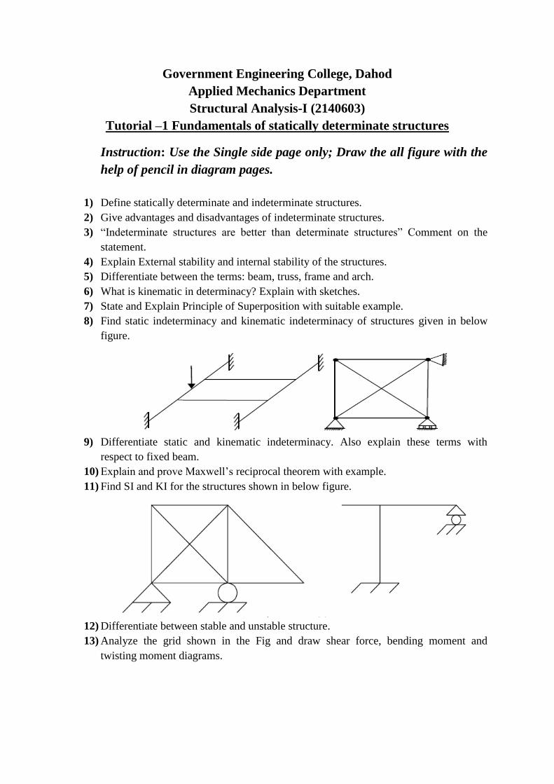
8) Find static indeterminacy and kinematic indeterminacy of structures given in below
figure.
9) Differentiate static and kinematic indeterminacy. Also explain these terms with
respect to fixed beam.
10) Explain and prove Maxwell‟s reciprocal theorem with example.
11) Find SI and KI for the structures shown in below figure.
12) Differentiate between stable and unstable structure.
13) Analyze the grid shown in the Fig and draw shear force, bending moment and
twisting moment diagrams.
15) Find static indeterminacy and kinematic indeterminacy of structures.
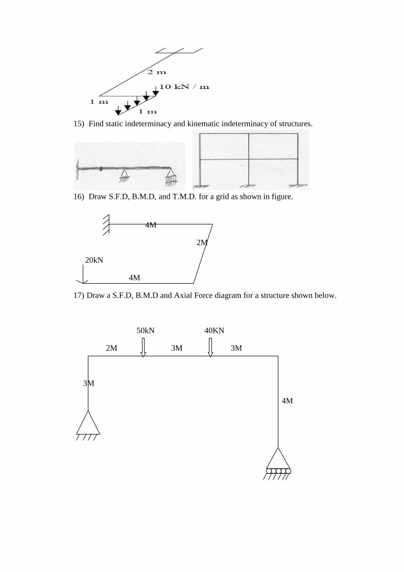
16) Draw S.F.D, B.M.D, and T.M.D. for a grid as shown in figure.
4M
2M
20kN
4M
17) Draw a S.F.D, B.M.D and Axial Force diagram for a structure shown below.
50kN 40KN
2M 3M 3M
3M
4M
Tutorial-2 Displacement of Determinate Beams and Plane Truss
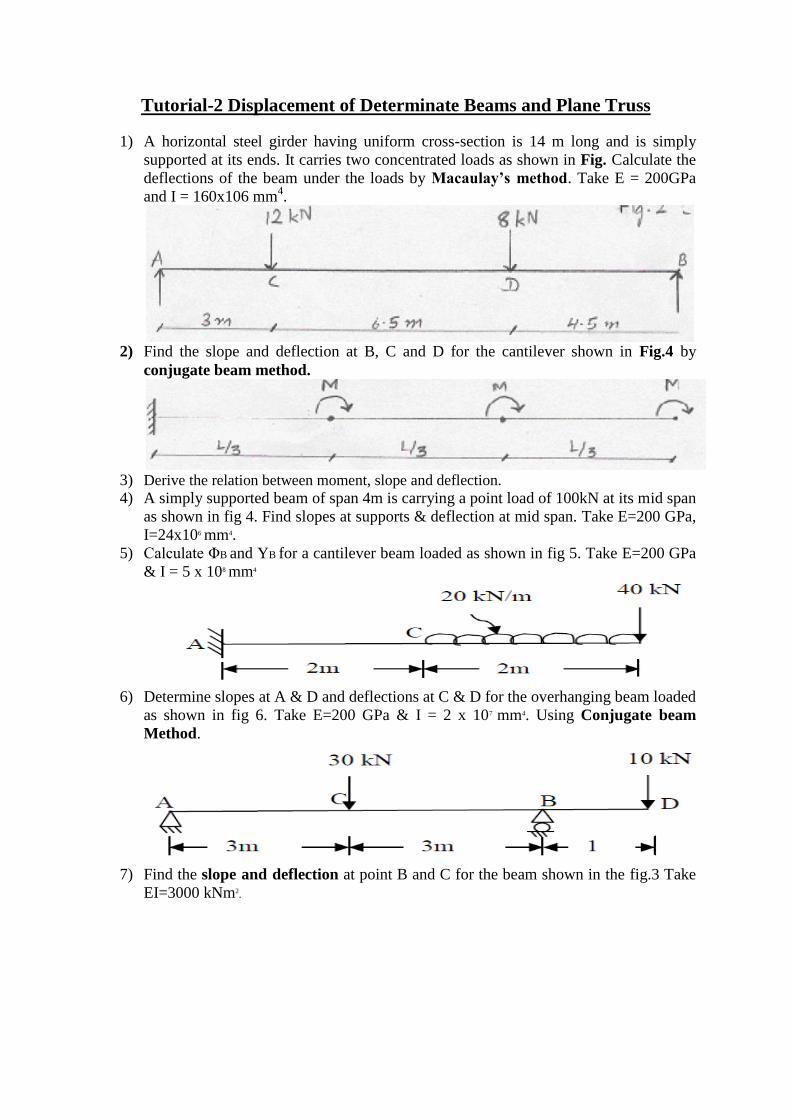
1) A horizontal steel girder having uniform cross-section is 14 m long and is simply
supported at its ends. It carries two concentrated loads as shown in Fig. Calculate the
deflections of the beam under the loads by Macaulay’s method. Take E = 200GPa
and I = 160x106 mm4.
2) Find the slope and deflection at B, C and D for the cantilever shown in Fig.4 by
conjugate beam method.
3) Derive the relation between moment, slope and deflection. 4) A simply supported beam of span 4m is carrying a point load of 100kN at its mid span
as shown in fig 4. Find slopes at supports & deflection at mid span. Take E=200 GPa,
I=24x106 mm4.
5) Calculate ΦB and YB for a cantilever beam loaded as shown in fig 5. Take E=200 GPa
& I = 5 x 108 mm4
6) Determine slopes at A & D and deflections at C & D for the overhanging beam loaded
as shown in fig 6. Take E=200 GPa & I = 2 x 107 mm4. Using Conjugate beam
Method.
7) Find the slope and deflection at point B and C for the beam shown in the fig.3 Take
EI=3000 kNm2.
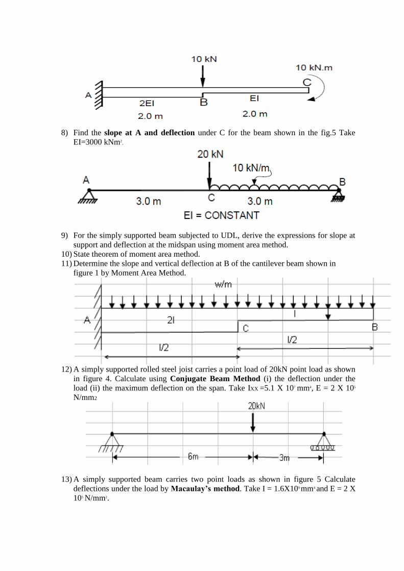
8) Find the slope at A and deflection under C for the beam shown in the fig.5 Take
EI=3000 kNm2.
9) For the simply supported beam subjected to UDL, derive the expressions for slope at
support and deflection at the midspan using moment area method.
10) State theorem of moment area method.
11) Determine the slope and vertical deflection at B of the cantilever beam shown in
figure 1 by Moment Area Method.
12) A simply supported rolled steel joist carries a point load of 20kN point load as shown
in figure 4. Calculate using Conjugate Beam Method (i) the deflection under the
load (ii) the maximum deflection on the span. Take IXX =5.1 X 107 mm4, E = 2 X 10⁵
N/mm2
13) A simply supported beam carries two point loads as shown in figure 5 Calculate
deflections under the load by Macaulay’s method. Take I = 1.6X109 mm4 and E = 2 X
105 N/mm2.
14) Concentrated loads of magnitude 40 kN, 80 kN, 80 kN and 100 kN at 2 m gap
between each other crosses a 12 m span simply supported beam from right to left.
Calculate the maximum shear force and bending moment at a section 4 m from left
support.
15) For the beam shown in Fig. 4 determine the deflection and slope at C using
Macaulay’s method.
16) Find out slope and deflection at C for the beam shown in Fig. 7 by conjugate beam
method.
17) Find the deflection and slope for a cantilever beam shown in Fig. 1, using moment
area method.
18) Find the deflection and slope under load 100 kN using conjugate beam method.
Refer Fig. 2. E = 200 GPa and I = 150 x 106 mm4.
19) Find the deflection at the center of beam by conjugate beam method for Fig. 3. E =
200 GPa and I = 2 x 108 mm4
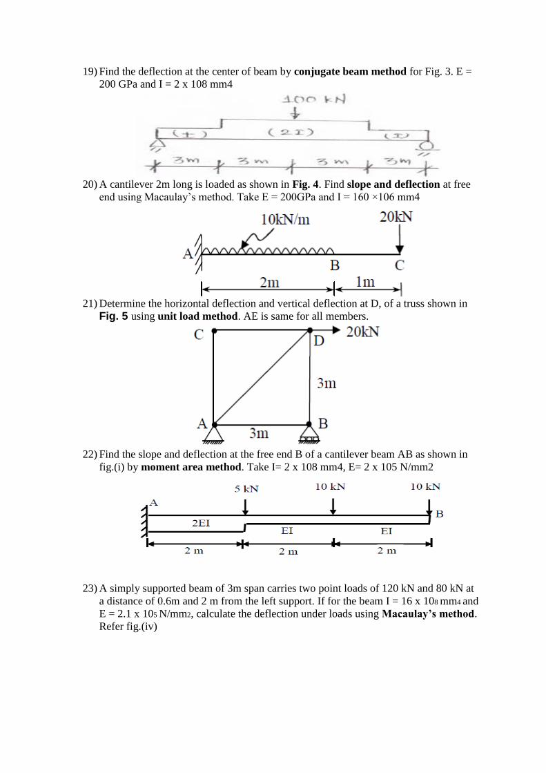
20) A cantilever 2m long is loaded as shown in Fig. 4. Find slope and deflection at free
end using Macaulay‟s method. Take E = 200GPa and I = 160 ×106 mm4
21) Determine the horizontal deflection and vertical deflection at D, of a truss shown in
Fig. 5 using unit load method. AE is same for all members.
22) Find the slope and deflection at the free end B of a cantilever beam AB as shown in
fig.(i) by moment area method. Take I= 2 x 108 mm4, E= 2 x 10⁵ N/mm2
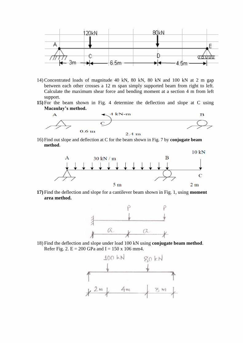
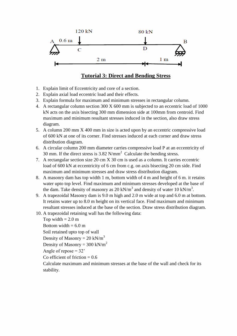
23) A simply supported beam of 3m span carries two point loads of 120 kN and 80 kN at
a distance of 0.6m and 2 m from the left support. If for the beam I = 16 x 108 mm4 and
E = 2.1 x 10⁵ N/mm2, calculate the deflection under loads using Macaulay’s method.
Refer fig.(iv)
Tutorial 3: Direct and Bending Stress
1. Explain limit of Eccentricity and core of a section.
2. Explain axial load eccentric load and their effects.
3. Explain formula for maximum and minimum stresses in rectangular column.
4. A rectangular column section 300 X 600 mm is subjected to an eccentric load of 1000
kN acts on the axis bisecting 300 mm dimension side at 100mm from centroid. Find
maximum and minimum resultant stresses induced in the section, also draw stress
diagram.
5. A column 200 mm X 400 mm in size is acted upon by an eccentric compressive load
of 600 kN at one of its corner. Find stresses induced at each corner and draw stress
distribution diagram.
6. A circular column 200 mm diameter carries compressive load P at an eccentricity of
30 mm. If the direct stress is 3.82 N/mm2 Calculate the bending stress.
7. A rectangular section size 20 cm X 30 cm is used as a column. It carries eccentric
load of 600 kN at eccentricity of 6 cm from c.g. on axis bisecting 20 cm side. Find
maximum and minimum stresses and draw stress distribution diagram.
8. A masonry dam has top width 1 m, bottom width of 4 m and height of 6 m. it retains
water upto top level. Find maximum and minimum stresses developed at the base of
the dam. Take density of masonry as 20 kN/m3 and density of water 10 kN/m
3.
9. A trapezoidal Masonry dam is 9.0 m high and 2.0 m wide at top and 6.0 m at bottom.
It retains water up to 8.0 m height on its vertical face. Find maximum and minimum
resultant stresses induced at the base of the section. Draw stress distribution diagram.
10. A trapezoidal retaining wall has the following data:
Top width = 2.0 m
Bottom width = 6.0 m
Soil retained upto top of wall
Density of Masonry = 20 kN/m3
Density of Masonry = 300 kN/m2
Angle of repose = 32‟
Co efficient of friction = 0.6
Calculate maximum and minimum stresses at the base of the wall and check for its
stability.
Tutorial 4: COLUMN AND STRUTS
1) State the assumptions made in the Euler‟s theory for long column.
2) With the help of sketches explain effective length of column for different end
condition.
3) Derive an expression for crippling load when one end of column is fixed and the other
end is free.
4) Derive an expression for crippling load when one end of column is fixed and the other
end is hinged.
5) A column of height 8.0 m is fixed at one end and hinged at other end.The cross-
section of column is a hollow square of external size 400 mm and internal size 300
mm.Determine the safe load the column can carry by using Euler‟s Formula.Take E=
2 x 10⁵ N/mm2 and F.O.S=2
6) A hollow cast iron column has outside diameter 200mm and thickness of 20mm. It is
4.5m long and fixed at both ends .Calculate the safe load and ratio of Euler‟s and
Rankine‟s critical load. For cast iron Fc= 550N/mm2, α =1/1600 and E= 0.8 x 10⁵
N/mm2
7) A circular column has both end hinged with length of 6.0 m and diameter of 160 mm. If
the yield strength of the material is 410 N/mm2 and rankine‟s constant is 1/4800,
calculate Euler‟s critical load and rankine‟s critical load.
8) A hollow cylindrical cast iron column is 4m long with both ends fixed. Find the
minimum diameter of the column if it has to carry a safe load of 250 Kn with a factor
of safety of 5. Take internal diameter as 0.8 times the external diameter. Take σc =
500MPa and Rankine‟s constant α = 1/1600.
9) A T-section having flange 180 x 15 mm and web 235 x 10 mm is used as a column
with both ends fixed.Find safe axixal load on column.Take fc=335 N/mm2 α =
1/7500 and F.O.S=3 .
10) A 250 mm x 125 mm I-section is used as a column of length 5 m,one end fixed and
other hinged.using Rankine‟s constant and FOS 3, find safe axial load.
Area of I-section =47.55 cm2
Ix=5131.6 cm4 Iy=334.5 cm4 fc=315 α = 1/7500
Tutorial 5: ARCHES CABLES AND SUSPENSION BRIDGES
1) A three hinged parabolic arch of 20 m span and 4 m central rise carries a point load of 150
kN at 4 m from left side support. Calculate normal thrust and shear force at section under
load. Draw BMD.
2) Derive the general equation of a cable from the first principle.
3) A suspension cable having supports at the same level has a span of 30m and a maximum
dip of 3m. The cable is loaded with a uniformly distributed load of 10 kN/m throughout its
length. Find the maximum tension in the cable.
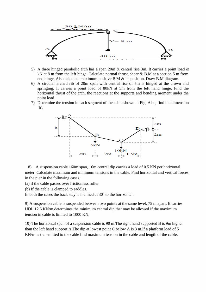
4) A symmetrical three hinged parabolic arch of span 40 m and rise 8m carries uniformly
distributed load of 30 kN/m over the left half of the span. The hinges are provided at the
support and center of the arch. Calculate the bending moment, radial shear and normal
thrust at a distance of 10m from the left support. Refer fig.
5) A three hinged parabolic arch has a span 20m & central rise 3m. It carries a point load of 15
kN at 8 m from the left hinge. Calculate normal thrust, shear & B.M at a section 5 m from left
end hinge. Also calculate maximum positive B.M & its position. Draw B.M diagram.
6) A circular arched rib of 20m span with central rise of 5m is hinged at the crown and
springing. It carries a point load of 80kN at 5m from the left hand hinge. Find the
horizontal thrust of the arch, the reactions at the supports and bending moment under the
point load.
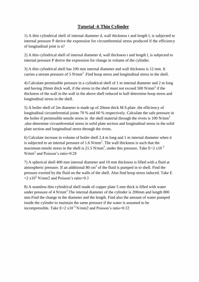
7) Determine the tension in each segment of the cable shown in Fig. Also, find the dimension
„h‟.
8) A suspension cable 160m span, 16m central dip carries a load of 0.5 KN per horizontal
meter. Calculate maximum and minimum tensions in the cable. Find horizontal and vertical forces
in the pier in the following cases.
(a) if the cable passes over frictionless roller
(b) If the cable is clamped to saddles.
In both the cases the back stay is inclined at 300 to the horizontal.
9) A suspension cable is suspended between two points at the same level, 75 m apart. It carries
UDL 12.5 KN/m determines the minimum central dip that may be allowed if the maximum
tension in cable is limited to 1000 KN.
10) The horizontal span of a suspension cable is 90 m.The right hand supported B is 9m higher
than the left hand support A.The dip at lowest point C below A is 3 m.If a platform load of 5
KN/m is transmitted to the cable find maximum tension in the cable and length of the cable.
Tutorial -6 Thin Cylinder
1) A thin cylindrical shell of internal diameter d, wall thickness t and length l, is subjected to
internal pressure P derive the expression for circumferential stress produced if the efficiency
of longitudinal joint is n?
2) A thin cylindrical shell of internal diameter d, wall thickness t and length l, is subjected to
internal pressure P derive the expression for change in volume of the cylinder.
3) A thin cylindrical shell has 100 mm internal diameter and wall thickness is 12 mm. It
carries a stream pressure of 5 N/mm2 .Find hoop stress and longitudinal stress in the shell.
4) Calculate permissible pressure in a cylindrical shell of 1 m internal diameter and 2 m long
and having 20mm thick wall, if the stress in the shell must not exceed 500 N/mm2 if the
thickness of the wall in the wall in the above shell reduced to half determine hoop stress and
longitudinal stress in the shell.
5) A boiler shell of 2m diameter is made up of 20mm thick M.S.plate .the efficiency of
longitudinal circumferential joints 70 % and 60 % respectively. Calculate the safe pressure in
the boiler if permissible tensile stress in the shell material through the rivets is 100 N/mm2
.also determine circumferential stress in solid plate section and longitudinal stress in the solid
plate section and longitudinal stress through the rivets.
6) Calculate increase in volume of boiler shell 2.4 m long and 1 m internal diameter when it
is subjected to an internal pressure of 1.6 N/mm2. The wall thickness is such that the
maximum tensile stress in the shell is 21.5 N/mm2, under this pressure. Take E=2 x10
5
N/mm2 and Poisson‟s ratio=0.28
7) A spherical shell 400 mm internal diameter and 10 mm thickness is filled with a fluid at
atmospheric pressure. If an additional 80 cm3 of the fluid is pumped in to shell. Find the
pressure exerted by the fluid on the walls of the shell. Also find hoop stress induced. Take E
=2 x10⁵ N/mm2 and Poisson‟s ratio=0.3
8) A seamless thin cylindrical shell made of copper plate 5 mm thick is filled with water
under pressure of 4 N/mm2.The internal diameter of the cylinder is 200mm and length 800
mm.Find the change in the diameter and the length. Find also the amount of water pumped
inside the cylinder to maintain the same pressure if the water is assumed to be
incompressible. Take E=2 x10 5
N/mm2 and Poisson‟s ratio=0.32
Tutorial-7 Fixed Beams and Consistent Deformation Method
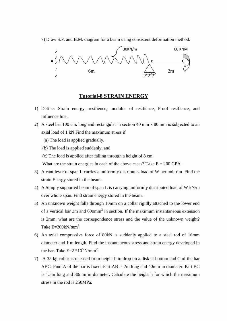
1) Calculate the support moments for a beam shown below by Fixed beam.
20kN/m
A B
3m 3m
2) Find the support moments and draw S.F. and B.M. diagram for a beam shown in
figure. by Fixed beam. 80kN
A B
2m 4m
3) A fixed beam of length 4 m is subjected to loads as shown in figure below. Find the
end moments are reactions at supports by Fixed beam.
5kN
3m 1m
40kNm
4) Analyze the beam shown in figure by consistent deformation method. Consider MA as
a redundant.
20 KN
A B C
4m 1m
5) Draw S.F. and B.M. diagram for a beam using consistent deformation method MA as
a redundant.
60kN 15kN/m
A 3m 3m B 2m C
6) Draw S.F and B.M diagram for a beam using consistent deformation method. Consider
MA as a redundant.
A 20 Kn/m B C
8m 2m
7) Draw S.F. and B.M. diagram for a beam using consistent deformation method.
30KN/m 60 KNM
A B C
6m 2m
Tutorial-8 STRAIN ENERGY
1) Define: Strain energy, resilience, modulus of resilience, Proof resilience, and
Influence line.
2) A steel bar 100 cm. long and rectangular in section 40 mm x 80 mm is subjected to an
axial load of 1 kN Find the maximum stress if
(a) The load is applied gradually.
(b) The load is applied suddenly, and
(c) The load is applied after falling through a height of 8 cm.
What are the strain energies in each of the above cases? Take E = 200 GPA.
3) A cantilever of span L carries a uniformly distributes load of W per unit run. Find the
strain Energy stored in the beam.
4) A Simply supported beam of span L is carrying uniformly distributed load of W kN/m
over whole span. Find strain energy stored in the beam.
5) An unknown weight falls through 10mm on a collar rigidly attached to the lower end
of a vertical bar 3m and 600mm2 in section. If the maximum instantaneous extension
is 2mm, what are the correspondence stress and the value of the unknown weight?
Take E=200kN/mm2.
6) An axial compressive force of 80kN is suddenly applied to a steel rod of 16mm
diameter and 1 m length. Find the instantaneous stress and strain energy developed in
the bar. Take E=2 *105
N/mm2.
7) A 35 kg collar is released from height h to drop on a disk at bottom end C of the bar
ABC. Find A of the bar is fixed. Part AB is 2m long and 40mm in diameter. Part BC
is 1.5m long and 30mm in diameter. Calculate the height h for which the maximum
stress in the rod is 250MPa.
8) A 10mm diameter mild steel bar of length 1.5m is stressed by a weight of 120N
dropping freely through 20mm before commencing to stretch the bar. Find the
maximum instantaneous extension and stress in the bar. Take E=2 *105
N/mm2
9) A bar of a certain metal 40 mm diameter and 1.2 m long has collar securely fitted to
one end. It is suspended vertically with the collar at the lower end. And a tensile load
of 22.5 KN is gradually applied to the collar producing an extension in the bar of
0.275 mm.Find the height from which this load could dropped on to the collar if
maximum tensile stress in the bar is to be 92.5 N/mm2
10) An elevator of mass 2000 kg is being lowered at the rate of 2 m/s. The hoisting drum
is stopped suddenly when 30 m of the cable have been unwrapped. If the cross-section
area of the cable is 600 mm2 and E=200GPa compute the maximum stress in cable.
Neglect self-weight of the cable.