gps-95cp operations manual
TRANSCRIPT

- 1 -
GPS-95CP
OPERATIONS MANUAL
- 2 -
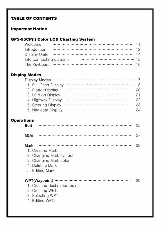
TABLE OF CONTENTS
Important Notice
GPS-95CP(i) Color LCD Charting System
Welcome ……………………………………………………… 11
Introduction ……………………………………………………… 12
Display Unite ……………………………………………………… 14
Interconnecting diagram …………………………………… 15
The Keyboard ……………………………………………………… 16
Display Modes
Display Modes ……………………………………………………… 17
1. Full Chart Display …………………………………………… 18
2. Plotter Display …………………………………………… 20
3. Lat/Lon Display …………………………………………… 21
4. Highway Display …………………………………………… 22
5. Steering Display …………………………………………… 23
6. Nav data Display …………………………………………… 24
Operations
Edit ……………………………………………………………… 25
MOB ……………………………………………………………… 27
Mark ……………………………………………………………… 28
1. Creating Mark
2. Changing Mark symbol
3. Changing Mark color
4. Deleting Mark
5. Editing Mark.
WPT(Waypoint) …………………………………………………… 29
1. Creating destination point
2. Creating WPT.
3. Selecting WPT.
4. Editing WPT.

- 3 -
Route ……………………………………………………………… 30
1. Instant Route
2. Creating Route
3. Selecting Route
4. Deleting Route
5. Reversing Route
6. Setting Point
7. Edit the existing route
8. Editing Route
Track ……………………………………………………………… 31
1. Track On/Off
2. Changing Track Color
3. Deleting Track
4. Change Track page
5. Loading Track
User Data ………………………………………………………… 31
Display On/Off ……………………………………………………… 32
Map Orientation …………………………………………………… 32
1. True motion
2. North up
3. Course up
4. Head up
GPS Setup 1/2 ……………………………………………………… 33
1. Datum
2. Satellite Information
3. Latitude Modification
4. Longitude Modification
5. Smoothing set
6. Average COG.
7. Average SOG.
8. Lat/Lon Unit
9. GPS Receiving Port
0. Coordinate System

- 4 -
Setup 1/2 ……………………………………………………… 34
1. Distance/Speed unit
2. Present Position Size
3. Track Size
4. Track Display Interval
5. Time Interval
6. Distance Interval
7. Heading Line Length
8. True/Magnetic
9. Compass Modification
0. TD Setup
Setup 2/2 ……………………………………………………… 35
1. Displaying Time Setup
2. Data Output
3. Land Color Select
4. Chart Change
5. Reset
6. WPT Name Font Size
7. SOG Setup
8. Save Track
9. Load Track
0. Depth unit
Maintenance ……………………………………………………… 37
1. System Information
2. Chart Information
3. Keyboard Test
4. GPS Simulator
5. Language
Alarms ………………………………………………………………… 38
1. Arrival Alarm
2. Arrival Radius
3. XTE Alarm
4. XTE Radius
5. Anchor Alarm
6. Anchor Radius
- 5 -
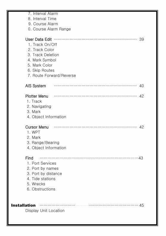
7. Interval Alarm
8. Interval Time
9. Course Alarm
0. Course Alarm Range
User Data Edit ……………………………………………………… 39
1. Track On/Off
2. Track Color
3. Track Deletion
4. Mark Symbol
5. Mark Color
6. Skip Routes
7. Route Forward/Reverse
AIS System ……………………………………………………… 40
Plotter Menu ……………………………………………………… 42
1. Track
2. Navigating
3. Mark
4. Object Information
Cursor Menu ……………………………………………………… 42
1. WPT
2. Mark
3. Range/Bearing
4. Object Information
Find …………………………………………………………………43
1. Port Services
2. Port by names
3. Port by distance
4. Tide stations
5. Wrecks
6. Obstructions
Installation ………………………………………………………………… 45
Display Unit Location

- 6 -
Display Unit Installation
Power Connection
Reference ………………………………………………………………… 47
Care and Cleaning
NMEA
GPS ………………………………………………………………………… 48
How GPS works
Position Fixing Accuracy: HDOP
The Installation of The GPS ANT.

- 7 -
- 8 -
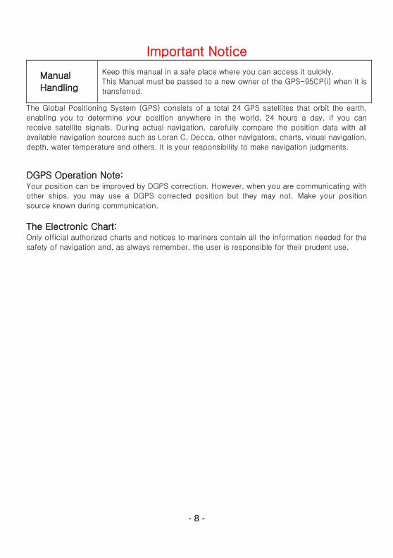
Important Notice
Manual
Handling
Keep this manual in a safe place where you can access it quickly.
This Manual must be passed to a new owner of the GPS-95CP(i) when it is
transferred.
The Global Positioning System (GPS) consists of a total 24 GPS satellites that orbit the earth,
enabling you to determine your position anywhere in the world, 24 hours a day, if you can
receive satellite signals. During actual navigation, carefully compare the position data with all
available navigation sources such as Loran C, Decca, other navigators, charts, visual navigation,
depth, water temperature and others. It is your responsibility to make navigation judgments.
DGPS Operation Note: Your position can be improved by DGPS correction. However, when you are communicating with
other ships, you may use a DGPS corrected position but they may not. Make your position
source known during communication.
The Electronic Chart: Only official authorized charts and notices to mariners contain all the information needed for the
safety of navigation and, as always remember, the user is responsible for their prudent use.
- 9 -
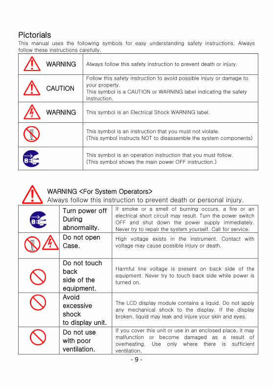
Pictorials This manual uses the following symbols for easy understanding safety instructions. Always
follow these instructions carefully.
WARNING Always follow this safety instruction to prevent death or injury.
CAUTION
Follow this safety instruction to avoid possible injury or damage to
your property.
This symbol is a CAUTION or WARNING label indicating the safety
instruction.
WARNING This symbol is an Electrical Shock WARNING label.
This symbol is an instruction that you must not violate.
(This symbol instructs NOT to disassemble the system components)
This symbol is an operation instruction that you must follow.
(This symbol shows the main power OFF instruction.)
WARNING <For System Operators>
Always follow this instruction to prevent death or personal injury. Turn power off
During
abnormality.
If smoke or a smell of burning occurs, a fire or an
electrical short circuit may result. Turn the power switch
OFF and shut down the power supply immediately.
Never try to repair the system yourself. Call for service.
Do not open
Case.
High voltage exists in the instrument. Contact with
voltage may cause possible injury or death.
Do not touch
back
side of the
equipment.
Harmful line voltage is present on back side of the
equipment. Never try to touch back side while power is
turned on.
Avoid
excessive
shock
to display unit.
The LCD display module contains a liquid. Do not apply
any mechanical shock to the display. If the display
broken, liquid may leak and injure your skin and eyes.
Do not use
with poor
ventilation.
If you cover this unit or use in an enclosed place, it may
malfunction or become damaged as a result of
overheating. Use only where there is sufficient
ventilation.

- 10 -
Installation Cautions <For service Personnel> Follow installation instructions to avoid personal injury and system malfunction.
Installation in
rigid location.
Mount your GPS-95CP(i) on a rigid frame or base to prevent your unit
from working loose.
Use correct
Installation
materials.
Use the installation materials provided in the standard accessory pack
only. If you use hardware of insufficient strength, your system may
loosen causing damage.
Keep away from
direct
sunlight.
Keep your system out of direct sunlight as it may become damaged by
overheating.
Keep away from
water.
Take care not to get water on or in your unit as it may be damaged
and/or cause an electrical shock.
Keep away from
heat
source.
Keep your system away from other heat source as it may malfunction, be
damaged, or burn.
Use correct
power
source.
Operate your system within the specified power voltage. An incorrect
power supply may cause damage.
Maintenance Cautions<For Maintenance Personnel> Use the following safety precaution internal inspection.
Discharge
capacitors.
High voltage may be retained in the capacitors in the high-tension
circuit several minutes after you have turned the power switch off.
Check that power is
OFF
To prevent an electrical injury due to erroneous power switching,
make sure that the main power supply and the system power switch
are both in the off position. Additionally, attach a safety label
showing that service is in progress.
Avoid EMI. Take care not to damage the ESDs (Electrostatic Sensitive Devices)
by static electricity from carpet and cloths.
Avoid dust. Wear a safety mask so as not to breath in dust during inspection or
cleaning inside your system instruments.

- 11 -
Operation Notes <For operators> Observe the following operation notes, otherwise the system failure or deterioration can result.
And periodical inspection and maintenance are required for keeping the system in an optimum
condition.
Backup important
data.
The waypoint and other registered data may become unreadable
by unexpected failure. We recommend recording this data
separately on optional user or SD-picture card.
WARNING
This product is designed to assist a navigation.
When you are sailing, use the certified chart from the Government or
IMO.

- 12 -
GPS-95CP(i) Color LCD Charting System
Welcome The GPS-95CP(i) Color LCD Charting System opens a new chapter of performance and
integration in vessel navigation system display and management. Whether you are a Cruiser or
Sport fisherman or both, GPS-95CP gives you the information you need.
CAUTION
The GPS-95CP(i) is a Color LCD Charting Systems that employs the latest in proven technology
to provide accurate navigation information. The Plotter functions of the GPS-95CP are totally
dependent upon the capability of the navigation source to provide accurate position information.
This device is only an aid to navigation. It should be used in conjunction with all other navigation
accuracy. For safety, always resolve any uncertainty before continuing navigation.
CAUTION
Electronic charts are derived from geographical data – including official government charts –
which we believe to be accurate. They are neither verified nor approved by Hydrographic
Authorities. Electronic charts in GPS-95CP(i) are designed only to ease and speed navigation
calculations and so must not be relied upon as a primary source of navigation information, but
rather a backup to the use of official government charts and prudent navigation habits.
There is no direct relationship between the color of water areas and their depth. The navigator
shall always query the area for depth information and use the official paper chart.
CAUTION
The performance of LCD displays are degraded by continuous direct exposure to ultraviolet rays.
Locate your GPS-95CP(i) Display away from direct sunlight. When not in use, keep the display
covered.
DISPLAY BREAKAGE WARNING
The LCD display module contains a liquid. If the display is broken and the liquid contacts your
skin, wash it off immediately in running water for 15 minutes. If the liquid contacts your eyes,
immediately flush your eyes with running water for 15 minutes. Contact a physician if any
abnormal symptom is experienced.

- 13 -
GPS-95CP(i) Color LCD Charting System
Introduction
The GPS-95CP(i) Color LCD Charting System is a premium multifunction command and control
center. It combines in one unit, display of worldwide cartography, and GPS navigation. GPS-
95CP(i) front panel keyboard and its large screen with wide viewing area make placement easy.
Although GPS-95CP(i) offers many advanced features, operation is simplified through the use of
popup menus similar to those found on personal computers. Also, the front panel keyboard has
specific keys for direct access to the most used functions and settings.
Equipment Supplied
GPS-95CP(i) Display
unit
GPS ANT.
(except 95CPi) Manual
Protector Mounting Bracket Knobs
Power cable

- 14 -
GPS-95CP(i) Color LCD Charting System
GETTING STARTED
This getting Started section will help you become acquainted with the displays and the front
panel keyboard functions of your GPS-95CP Color LCD Charting System. This section is
intended to demonstrate the main functions and basic operation of your GPS-95CP System.
More detailed procedures may be found in the Operation section.
GPS-95CP(i) has built-in simulators that present realistic displays of cartography and GPS.
Note: Simulators are interactive so the front panel keyboard can be used to browse through
menus and change setting in the same manner as actual operation. The internal simulators allow
GPS-95CP(i) to operate without having antennas or remote sensors connected. However, it is
necessary to connect the power cable to 12 to 36 Vdc power source. Please refer to Power
Connection in the installation section.
If GPS-95CP is already installed on your vessel, simulators are still useful for
familiarity with displays and practice with operating procedures.

- 15 -
GPS-95CP(i) Color LCD Charting System
Display Unit
The heart of the GPS-95CP(i) Color LCD Charting System is the display unit. Within the display
unit are the powerful central processor and integrated display system, built-in cartography. The
bright 4.3 inch active matrix color LCD, is easily viewed over a wide area on the bridge or nav
center.
Keyboard
Knobs
Mounting Bracket

- 16 -
GPS-95CP(i) Color LCD Charting System
Interconnecting diagram
MINI JACK
Connect to PC
(by Serial Port)
SD Card Slot
USB
Connect to PC
(by USB) C-MAP Slot
GPS Antenna
(Except 95CPi)
Power (12V ~ 36V)
Data In/Out (RX/TX)
Speaker

- 17 -
The Keyboard
[ZOOM-IN] Change the chart of scale bigger in plotter
[ZOOM-OUT] Change the chart of scale smaller in plotter
[MENU] Menu opens menu to select options
[GOTO] Cursor display: Place the cursor and press “GOTO’ to set WPT No cursor/Pointed WPT: Save WPT and set free the pointed WPT No cursor/No pointed WPT: List for WPT, route
[MAIN SCREEN]
Selects function to display on Full Chart Display, Plotter Display,
LAT/LOT Display, Highway Display, Steering Display, Nav data Display.
(* When the menu or the cursor appears, it’s used for ESC.
[ENTER] Completes pending selection or operation
[MARK/MOB]
Mark: Places a mark on the plotter main screen.
MOB: Is a special navigation function that immediately stores your
present position as a waypoint and activates navigation to the stored
coordinates.
[BRT/PWR] BRT: Brightness adjust the brightness in day mode or night.
PWR: Turns On/Off
[CURSOR PAD]
Cursor On and use to move the cursor, select menu items, scroll lists,
select options, change settings in plotter
(*To make the cursor deleted, press [MAIN SCREEN].
How to use [BRT/PWR]
Use PWR:
To turn off the power, keep pressing the [BRT/PWR] until the end of count down.
Use BRT:
Press [BRT/PWR] quickly and the brightness can be controlled. Use the arrow keys of the
cursor to control the brightness and the contrast.
Cursor pad
Zoom in & Zoom out
Select display mode & cancel

- 18 -
Display Modes
Your unit has six-display modes. Press the [MAIN SCREEN] key to choose a display mode. Each
time the key is pressed, the display mode changes in the sequence shown below.
[Full Chart Display] [Plotter Display]
[Lat/Lot Display] [Nav Data Display]
[Highway Display] [Steering Display]

- 19 -
Display Modes
1. Full Chart Display
This mode provides GPS information and the chart.
i) GPS Information
[GPS Information]
Present Position
Scale
Present position in
latitude and longitude
Course over Ground
T: True
M: Magnetic
Date
Track Information
Satellites Information
Receiver
status
Mark Information
Scale
Speed
over
Ground

- 20 -
Display Modes
ii) WPT Information iii) Cursor Information
WPT: WPT‘s name
Route: Point’s No of WPT
WPT in latitude and
longitude
Distance between the present
position and the WPT
Bearing between the present
position and the WPT
Estimated time to arrive
Cursor in latitude and
longitude
Distance from the present
position to the cursor
Bearing between the present
position and the cursor
- 21 -
Display Modes
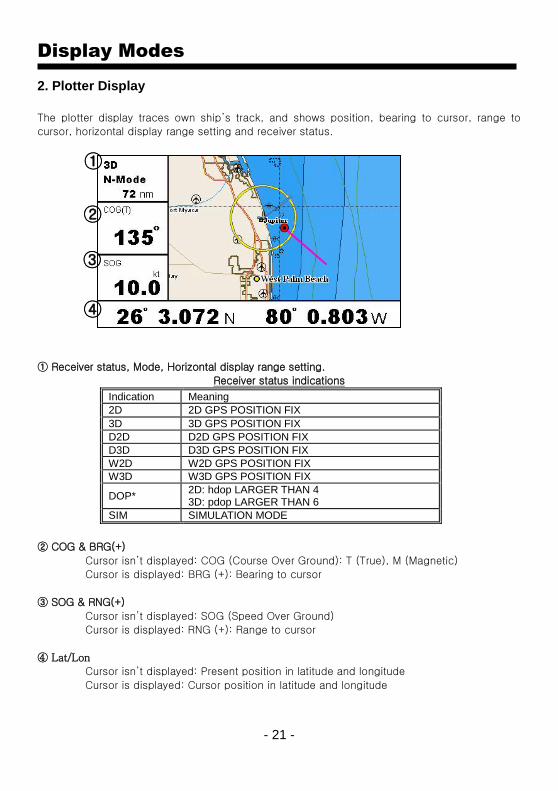
2. Plotter Display
The plotter display traces own ship’s track, and shows position, bearing to cursor, range to
cursor, horizontal display range setting and receiver status.
① Receiver status, Mode, Horizontal display range setting.
Receiver status indications
② COG & BRG(+)
Cursor isn’t displayed: COG (Course Over Ground): T (True), M (Magnetic)
Cursor is displayed: BRG (+): Bearing to cursor
③ SOG & RNG(+)
Cursor isn’t displayed: SOG (Speed Over Ground)
Cursor is displayed: RNG (+): Range to cursor
④ Lat/Lon
Cursor isn’t displayed: Present position in latitude and longitude
Cursor is displayed: Cursor position in latitude and longitude
Indication Meaning
2D 2D GPS POSITION FIX
3D 3D GPS POSITION FIX
D2D D2D GPS POSITION FIX
D3D D3D GPS POSITION FIX
W2D W2D GPS POSITION FIX
W3D W3D GPS POSITION FIX
DOP* 2D: hdop LARGER THAN 4 3D: pdop LARGER THAN 6
SIM SIMULATION MODE
①
②
③
④
- 22 -
Display Modes
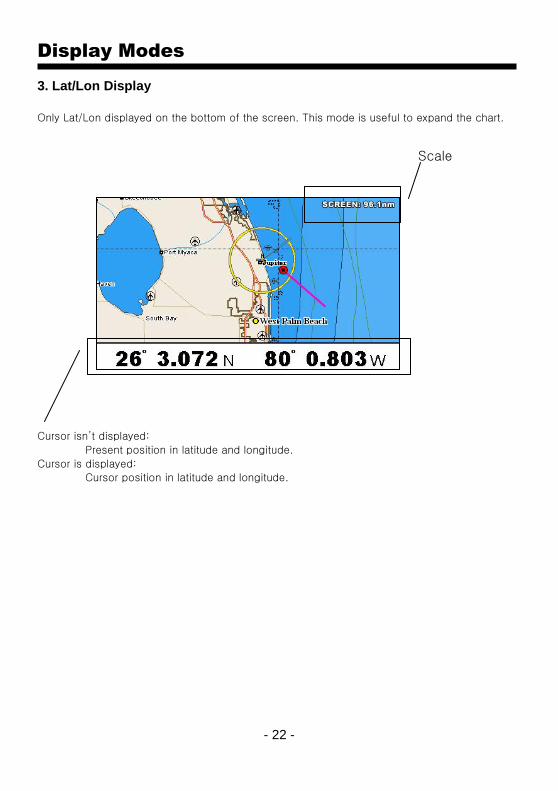
3. Lat/Lon Display
Only Lat/Lon displayed on the bottom of the screen. This mode is useful to expand the chart.
Cursor isn’t displayed:
Present position in latitude and longitude.
Cursor is displayed:
Cursor position in latitude and longitude.
Scale
- 23 -
Display Modes
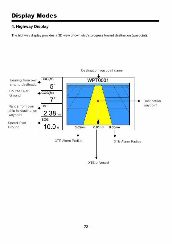
4. Highway Display The highway display provides a 3D view of own ship’s progress toward destination (waypoint).
Destination waypoint name
Destination
waypoint
Bearing from own
ship to destination
waypoint Course Over
Ground
Range from own
ship to destination
waypoint
Speed Over
Ground
XTE Alarm Radius
XTE of Vessel
XTE Alarm Radius
- 24 -
Display Modes
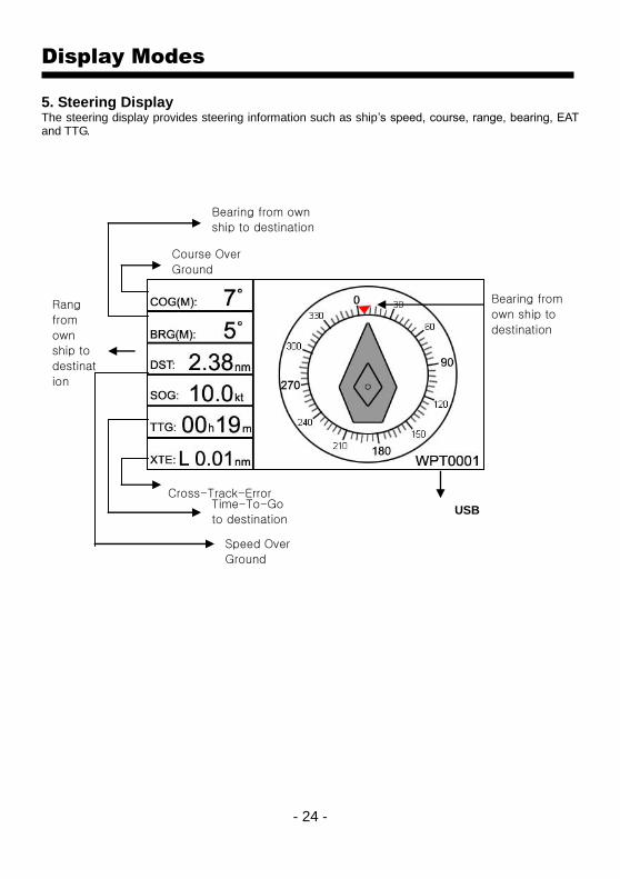
5. Steering Display The steering display provides steering information such as ship’s speed, course, range, bearing, EAT and TTG.
USB Connect to PC
(by USB)
Bearing from
own ship to
destination
Speed Over
Ground
Rang
from
own
ship to
destinat
ion
Time-To-Go
to destination
Bearing from own
ship to destination
waypoint Course Over
Ground
Cross-Track-Error
- 25 -
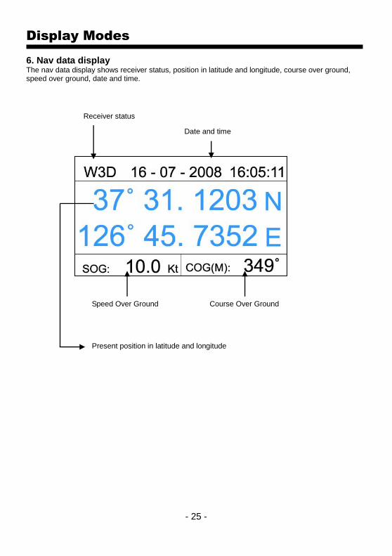
Display Modes
6. Nav data display The nav data display shows receiver status, position in latitude and longitude, course over ground, speed over ground, date and time.
Receiver status
Date and time
Speed Over Ground Course Over Ground
Present position in latitude and longitude

- 26 -
Operations
Edit Edit numbers, symbols, and colors of Mark, WPT, and Route.
1. Editing Character
[←],[→]:
move the position
[↑],[↓]:
move the bar
[▲][▼]:
input letters
[ENTER]:
choice and input
2. Editing Number
[←],[→]:
move the position
[↑],[↓]:
change the number
[ENTER]:
choice and input
- 27 -
Operations
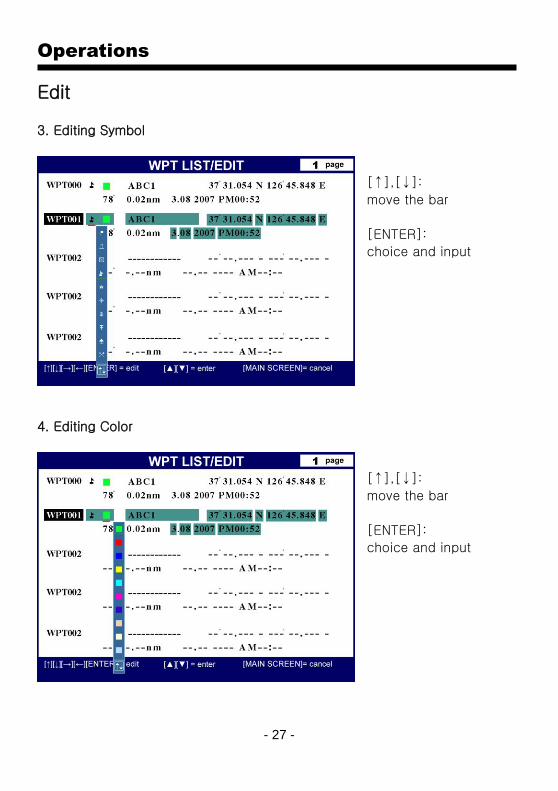
Edit
3. Editing Symbol
[↑],[↓]:
move the bar
[ENTER]:
choice and input
4. Editing Color
[↑],[↓]:
move the bar
[ENTER]:
choice and input

- 28 -
Operations
MOB(Man Over Board) MOB is a special navigation function that immediately stores your present position as a waypoint and activates navigation to the stored coordinates. MOB waypoints are stored in the waypoint library at the next available position in the WPT mark list. MOB waypoints appear in the list and on the Plotter Min Screen in the same manner as normal waypoints.
(※ MOB available only without the cursor) ▶ [MARK/MOB]->[ENTER]
※MOB/Mark key
- without the cursor : MOB or inputting a mark at the present position
MOB :
▶ [MOB/MARK] -> [ENTER]
Mark :
▶ [MOB/MARK] -> all keys except [ENTER]
- with cursor : only mark is available at the cursor
▶ [MOB/MARK]

- 29 -
Operations
MARK Mark means that a user indicates an important position or a point such as a fish heaven or a danger area for sailing. This is one of the most important functions in the plotter.
1. Creating Mark - Cursor isn’t displayed :
▶ [MARK/MOB]->press any keys except [ENTER]. (※ inputting a mark at the present position) - Cursor is displayed :
▶ move the position to where you want and press [MARK/MOB]. - addition in the edit of mark: (※PLS, refer the edit list) 2. Changing Mark symbol Ten symbols are for Mark. i) Cursor isn’t displayed :
▶ [MENU] -> [8.User data Edit] -> [4. Mark Symbol]->[←][→] ii) Cursor is displayed :
▶ [ENTER]->[1.Mark]->[2. Mark Symbol]->[←],[→] 3. Changing Mark color Ten colors are for Mark. i) Cursor isn’t displayed :
▶ [MENU] -> [8.User data Edit] -> [5. Mark Color]->[←][→] ii) Cursor is displayed :
▶ [ENTER]->[1.Mark]->[3. Mark Color]->[←],[→] 4. Deleting Mark i) Delete the mark with the cursor. Press the key, [Cursor pad] and move it to the mark position. Get to the mark position on the center of the cursor and press the key, [MARK/MOB]. It will be deleted on the screen. ii) Delete the mark in the list (※PLS, refer the edit list) 5. Editing Mark ▶ [MENU]->[1.Edit]->[3.Mark Edit] i) Creating Mark
▶ [↑][↓]->[ENTER] ii) Editing Mark
▶ [↑][↓]->[ENTER] iii) Deleting Mark
▶ [↑][↓]->[MENU]->[ENTER] iv) All deleting Mark
▶ [MENU]->[MENU]

- 30 -
Operations
Waypoint(WPT) Waypoints may be entered and stored in the waypoint library by any of two different methods. You may use the cursor to select locations from a chart, or store vessel present position as a waypoint
1. Creating destination point You can place the destination point and immediately start navigating to it. ▶ [GOTO]->[ENTER] - Saving destination: when saving the present instant route ▶ [GOTO]->[ENTER] - Deleting Destination: when deleting the present instant route ▶ [GOTO]->[MENU] 2. Creating WPT i) Cursor isn’t displayed :
▶ [ENTER]->[2.Waypoint]->[ENTER] ii) Cursor is displayed :
▶ [ENTER]->[3.Waypoint]->[ENTER] 3. Selecting WPT ▶ [GOTO]->[1.WPT List/Edit]->[↑][↓]->[GOTO] 4. Editing WPT ▶ [MENU] → [1.Edit] → [1.WPT.Edit] i) Creating WPT
▶ [↑][↓]->[ENTER] ii) Editing WPT
▶ [↑][↓]->[ENTER] iii) Deleting WPT
▶ [↑][↓]->[MENU]->[ENTER] iv) All deleting WPT
▶ [MENU]->[MENU]
- 31 -
Operations
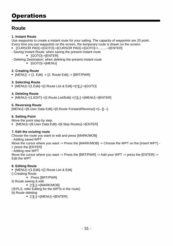
Route 1. Instant Route Use waypoints to create a instant route for your sailing. The capacity of waypoints are 20 point. Every time you put waypoints on the screen, the temporary route is drawn on the screen. ▶ [CURSOR PAD]->[GOTO]->[CURSOR PAD]->[GOTO]->.........->[ENTER] - Saving Instant Route: when saving the present instant route ▶ [GOTO]->[ENTER] - Deleting Destination: when deleting the present instant route ▶ [GOTO]->[MENU] 2. Creating Route ▶ [MENU] -> [1. Edit] -> [2. Route Edit] -> [BRT/PWR] 3. Selecting Route ▶ [MENU]->[1.Edit]->[2.Route List & Edit]->[↑][↓]->[GOTO] 4. Deleting Route ▶ [MENU]->[1.EDIT]->[2.Route List/Edit]->[↑][↓]->[MENU]->[ENTER] 5. Reversing Route [MENU]->[8.User Data Edit]->[0.Route Forward/Reverse]->[←][→] 6. Setting Point Move the point step by step. ▶ [MENU]->[8.User Data Edit]->[9.Skip Routes]->[ENTER] 7. Edit the existing route Choose the route you want to eidt and press [MARK/MOB] - Adding saved WPT Move the cursor where you want -> Press the [MARK/MOB] -> Choose the WPT on the [Insert WPT] -> press the [ENTER] - Adding new WPT Move the cursor where you want -> Press the [BRT/PWR] -> Add your WPT -> press the [ENTER] -> Edit the WPT 8. Editing Route ▶ [MENU]->[1.Edit]->[2.Route List & Edit] i) Creating Route
▶ Press [BRT/PWR] ii) Route seeing & edit
▶ [↑][↓]->[MARK/MOB] (※ PLS, refer Editing for the WPTs in the route) iii) Route deleting
▶ [↑][↓]->[MENU]->[ENTER]
- 32 -
Operations
Track The Track function provides a record of the path over which your vessel has traveled. A track is a series of lines connecting points of vessel present position which are plotted at wither time or distance intervals. Tracks are recorded and stored one at a time. AQUA supports five different tracks, each has up to ten thousand (20,000) points of track history. Tracks are displayed on the Main Plotter Screen in any user selectable combination from none to five. Current track status is displayed on the lower line of the GPS area of the information display. Track number, on/off condition, and number of track points used are presented.
1. Track ON/OFF ▶ [ENTER]->[1.Track]->[←][→]. For displaying on/off, use the arrow keys, right and left. 2. Changing Track Color ▶ [MENU]->[8.User Data Edit]->[2. Track Color]. For choosing the color you want, use the arrow keys, right and left. 3. Deleting Track ▶ [MENU]->[8.User Data Edit]->[3. Track Deletion]->Choose the color you want to delete ->[ENTER] (* If you want to delete all tracks, choose “All Delete”) 4. Changing Track page Saving 10,000 points are available in each page. ▶ [MENU]->[4.Setup 1/2]->[0.Track Pages]->[←][→] 5. Loading Track Saving 10,000 points are available in each . ▶ [MENU]->[4.Setup 1/2]->[enter]->[9.Load track]->[ENTER]
User Data Save User Data(Back-up) ▶ Insert the SD card -> [MENU] -> [1. Edit] -> [6. Save User Data] -> [ENTER] *SD card must be a normal type. (mini SD and Mirco SD are not available) Please, kindly note that the maximum is 2GB.
Load User Data ▶ Insert the SD card -> [Menu] -> [1. Edit] -> [7. Load User Data] -> [ENTER] *SD card must be a normal type. (mini SD and Mirco SD are not available) Please, kindly note that the maximum is 2GB.

- 33 -
Operations
Display ON/OFF The menu selects icons or symbols and lines displayed ON/OFF.
▶ [MENU]->[2.Display ON/OFF]->[←][→] (* If you want to go to next page of the menu, press [MENU]) (* In C-MAP, it could be different from HY-chart.)
Map Orientation There are four display modes for Main Screen that involve the Plotter or Radar screen. Both Plotter and Radar mode change together regardless ok which one is active when a mode change is made. The display modes are: Normal mode, North up, Course up, Head up ▶ [MENU]->[9.Mode] 1. True motion: The True Motion display is oriented North up or South up depending upon the North/South setting found on the PLOTTER MENU. The difference between True Motion and North/South Up display is in the way the vessel position is presented. In True Motion mode, the vessel position symbol moves over the map while the map remains stationary. 2. North up: The North Up/South Up display is oriented North up or South up depending upon the North/South setting found on the PLOTTER MENU. For this mode setting the vessel present position remains fixed in the center of the Main Screen while the map moves under it. 3. Course up: The Course Up mode screen orientation is determined by whether or not navigation is in progress. During navigation vessel present position is in the center of the Main Screen and the course line to the destination waypoint is straight up. As your present position changes, the map moves under the stationary vessel symbol. If navigation is stopped, the Main Screen appears as North/South Up. 4. Head up For Head Up mode, vessel present position is fixed in the center of the Main Screen and vessel heading is upward. As your present position changes, the map moves under the vessel symbol.

- 34 -
Operations
GPS Setup It is available to control and confirm information in GPS receiver. ▶ [MENU]->[3.GPS Setup] GPS Setup 1/2 1. Datum: It shows GPS Datum. WGS-84, which is the worldwide standard is only available. 2. Satellite Information: It shows the receiving condition of the signal from satellites. 3. Latitude Modification: There could be a receiving signal error from satellites. If it is on the latitude, modify in the latitude modification. 4. Longitude Modification: There could be a receiving signal error from satellites. If it is on the longitude, modify in the longitude modification. 5. Smoothing set: How to set the calculation of Smoothng. OFF : No use. Mode 1: Calcalation in short time. Mode 2: Calcalation in long time.
(☞ The default setting is Mode 1.)
6. Average COG: It sets time by second for average bearing. It is a special function for a fishing boat.
(※ Although you set a time to the menu, it is unavailable if the menu, No. 5(Smoothing ser is off.)
(☞ The default setting is incorrect every the country.)
7. Average SOG: It sets time by second for average speed. It is a special function for a fishing boat.
(※ Although you set a time to the menu, it is unavailable if the menu, No. 5(Smoothing ser is off.)
(☞ The default setting is incorrect every the country.)
8. Lat/Lon Unit: It is to select the number of the unit for Lat/Lon.
(☞ The default setting is 4 unit.)
9. GPS Receiving Port: It is to select Inter receiver Interior or Exterior. The default setting is Interior.
0. Coordinate System: It sets coordinate system of GPS or Loran.
(☞The default setting is GPS.)

- 35 -
Operations
Setup It is available to set the menu or units for user’s visual confidence. (* For next page, press [MENU]) ▶ [MENU]->[4.Setup] Setup 1/2 1. Distance/Speed Unit: Select desired unit of measure for distance and speed. Choose from: nautical mile/knots (nm/kt), kilometer/kilometers per hour(km/kmh), yard/knot(yd/kt). cf) 1nm = 1.852km, 1kt /h= 1.852km/h, less than 1nm display in yard and over 1nm display in mile 2. Present Position Size: The size of the present position is adjustable from 0 to 9. The biggest size is ‘0’. 3. Track Size: The size of a track is selectable between thin and pan. 4. Track Display Interval: Track display interval is adjustable by distance or time. 5. Time Interval: If track interval is set in time, a track displays by track time interval. The track time interval and the maximum capacity is 10,000 points. 6. Distance Interval: If track interval is set in distance, a track displays by track distance interval. 7. Heading Line Length: The length of the heading line is adjustable from 50 until 300. The bigger number, the longer line. The heading line is used in modes of the true motion and the north/south up. 8. True/Magnetic: There is a difference degree where you are in the earth. This function is to modify the error from true and Magnetic. 9. Compass Modification: There could be a difference between the magnetic compass and the GPS compass. An error depends upon your area. It is necessary to use AUTO PILOT together with GPS Plotter. 0. TD setup It sets Chain, Pair, ASF.

- 36 -
Operations
Setup It is available to set the menu or units for user’s visual confidence. (* For previous page, press [MENU]) ▶ [MENU]->[4.Setup] Setup 2/2 1. Displaying Time Setup: Provides for local time offset (-12:00 to +13 hours in 1/2 hour steps) from UTC. 2. Data Output: AQUA can be connected with a radar and an autopilot, which needs to get a signal from the radar and the autopilot. These data are necessary to communicate with NMEA 0183.
DESCRIPTIONS CONTENTS OF DATA FIELD
$GPGGA Global Positioning System Fix Data
$GPGLL Geographic Position, Latitude/Longitude
$GPGSA GPS DOP and active satellites
$GPGSV GPS Satellites in View
$GPVTG Course and Ground Speed
$GPZDA Time & Date
$GPRMC Recommended Minimum Specific GPS/TRANSIT DATA
$GPAPB Satellites information
$GPXTE Cross-track error, measured
$GPBOD Bearing, origin to destination
$GPRMB Recommended minimum navigation information
3. Land Color Select: Choose the color of the land. (*This function is only available in HY-chart) 4. Chart Change: Choose the chart system. (HY-MAP/External MAP/C-MAP) 5. Reset All systems returns to the initial system.
▶ [ENTER] : reset without deleting user data. ▶ [GOTO]->[ENTER]: returning to the initial system from the releasing of factory.
(All user data will be deleted) 6. WPT Name Font Size Choose the font size of the WPT. 7. SOG Setup Control the abnormal speed an anchoring. 8. Save Track Current Track save to Track data. 9. Load Track Saved Track load to display

- 37 -
Operations
0. Depth unit Select the depth unit.
- M: Meter unit - Ft: Feet unit - FM: Femten unit

- 38 -
Operations
Maintenance It is necessary to check the system or the version for maintenance and demonstrate AQUA with the simulators ▶ [MENU]->[5.Maintance] 1. System Information It contains ID and the program version, and it has important information for maintenance and upgrade. 2. Chart Information: It contains the version of the chart, the datum and the number, which is necessary for maintenance and upgrade 3. Keyboard Test: It tests the keyboard if it’s working properly. 4. GPS Simulator: It is necessary for an indoor demonstration. The simulations of GPS plotter are two in the memory.
5. Language:
AQUA supports three different kinds of languages, English, Chinese, Arabic, Thai etc.
Pressing the [ENTER], AUQA turns off and reboot the system for the new language.
(☞ When the language does not come out, inquiry to purchase place.)

- 39 -
Operations
Alarm Special notices are necessary on sailing. AQUA has four kinds of alarm, arrival, out of the course, anchor and time. ▶ [MENU]->[7.Alarm] 1. Arrival Alarm: When you approach into the waypoint range, it gives you a notice with alarm. 2. Arrival Radius: It is to adjust the range of arrival from your waypoint. If you have a route, it changes to the next waypoint automatically. 3. XTE Alarm: If you are out of the course, it gives you a notice with alarm. 4. XTE Radius: It is to adjust the range of the off course. 5. Anchor Alarm: It is necessary when your vessel anchors. 6. Anchor Radius: If you vessel is out of the range of the anchor, it gives you notice with alarm. 7. Interval Alarm: It alarms every time you set. 8. Interval Time The time is available from one minute until sixty minutes. 9. Course Alarm: It alarms if it breaks into the setting area. 0. Course Alarm Range: It sets the range of the course alarm.

- 40 -
Operations
User Data Edit
It is possible to set the menu of user data.
(Track, Mark, WPT, Route)
▶ [MENU]->[8. User Data Edit]->[Enter]
1. Track On/Off
It is available to set start and stop the track.
2. Track Color
It is available to set the track color. Use curser to change the color.
3. Track Deletion
Press [ENTER]. “Track deletion” and the window is showed. Use the curser and select color
then press [ENTER] key. All tracks which are selected by color will be deleted.
4. Mark Symbol
It is available to change the Mark symbol. Use the curser to change symbol.
5. Mark Color
It is available to change the Mark color. Use the curser to change color.
6. Skip Routes
It is available to set up a next WPT in the Present preferred route. Press [ENTER].
7. Route Forward/Reverse
It is available to set up the route forward and reverse in the Present preferred route.

- 41 -
Operations
AIS System
AIS is an Automatic Identification System. It has been introduced to improve the safety of navigation by assisting in the efficient operation of ship to ship, ship reporting and VTS applications. The system should enable operators to obtain information from the ship automatically, requiring a minimum of involvement of ship’s personnel, and should have a high level of availability. Connecting to the chart plotter an AIS receiver, vessels with AIS transponder within VHF range are displayed on screen giving he skipper or navigator a visual interpretation of the data of nearby vessels. This improves safety, and specifically for collision avoidance reasons. 1.AIS system definitions
CPA Closest Point of Approach is the closest distance that will be achieved between your vessel and the tracked target, based on your vessel’s speed and direction and the target’s speed and direction.
CPA Alarm Occurs if CPA is less or equal to CPA Radius. This test is done for active targets only.
CPA Limit This is the distance from your vessel that a target may reach before a target is deemed a threat.
TCPA Time to Closest Point of Approach is the time remaining until the CPA will occur.
TCPA Alarm Occurs if TCPA is less or equal to TCPA Radius. This test is done for active targets only and if CPA value is less or equal to CPA Radius.
TCPA Limit This is the time remaining before the CPA is reached.
Name Name of ship, 20 characters.
MMSI Maritime Mobile Service Identity.
MMSI number A unique 9 digit number that is assigned to DSC radio station. It primarily registers the boat information in the U.S. Coast Guard’s national distress database for use in emergency situations.
Target It is a vessel equipped with AIS. Information about the targets is being received by AIS Receiver and displayed on the screen.
Active Target Target located within the Activation Range. Active target is represented by oriented triangle with COG and Heading vectors. Rate of turn may also be displayed.
Dangerous Target
Target detected by CPA or TCPA Alarm. Dangerous target is Active Target by definition. For better visibility Dangerous Target symbol is charged from basic color to red color.
Sleeping Target
Target located outside the Activation Range. Sleeping target is represented by a small oriented triangle.

- 42 -
Lost Target When the AIS info is not received from that vessel for 3.5minutes. The presentation will be marked X on the target.
2. AIS Setup It sets AIS on/off, AIS Scale, CPA Alarm, CPA Limit, TCPA Alarm, TCPA Limit.
▶ [MENU]->[3.GPS Setup]->[MENU]->[1.AIS Setup]
2-1. AIS on/off Turns the display of AIS targets overlay on the cartography ON or OFF. The default setting is OFF. 2-2. AIS Scale It is possible to setup AIS Targets with Scale, The default setting is 2nm. 2-3. CPA Alarm Turns ON/OFF the alarm. The default setting is OFF. 2-4. CPA Limit The values allowed are from 0.1nm to 10nm. The default setting is 0.1nm. 2-5. TCPA Alarm Turns ON/OFF the alarm. The default setting is OFF. 2-6. TCPA Limit The values allowed are from 1 to 50 min. The default setting is 1 min. It is a vessel equipped with AIS. Information about the targets is being received by AIS Receiver and displayed on the screen.
(☞ Refer to AIS Setup for GPS Setup 2/2 of AIS setup.)
3. Quick info on AIS target Press [ENTER] key on Target which wants to see. It shows Information of “AIS INFO” window. AIS INFO window 1. Name 2. MMSI number 3. Nationality 4. Navigation Status 5. Heading 6. COG 7. SOG 8. Longitude 9. Latitude 10. CPA 11. TCPA (* The baud of TX/RX is set up 38400 bps automatically when AIS is ON.)

- 43 -
Operations
Plotter Menu
Press [ENTER] key without cursor, it shows Plotter Menu. 1. Track It is possible to setup start and stop of Track. 2. Navigating It is possible to setup start and stop of Navigating. 3. Mark Mark is input on the Vessel Position. 4. Object Information It is possible to use Find function and to see map information at the Vessel Position.
☞ Information is Port Services, Tides, Lights, Wrecks, Rocks, Buoys, Beacon, Obstructions, Land
markers, etc.
☞ Find function works when press [Zoom in] key. Refer to description of find how use
Cursor Menu
Press [ENTER] with cursor, Cursor Menu will be showed up. 1. WPT WPT is input at position of cursor. 2. Mark WPT is input at position of Mark. 3. Range/Bearing Press [ENTER] to place where you want to make start point then move the cursor to place where you want. You can know Range and Bearing between start point and position of cursor on cursor info. 4. Object Information It is possible to use Find function and to see map information at the Vessel Position.
☞ Information is Port Services, Tides, Lights, Wrecks, Rocks, Buoys, Beacon, Obstructions, Land
markers, etc.
☞ Find function works when press [Zoom in] key. Refer to description of find how use
- 44 -
Operations
Find
The charplotter allows finding Nearest Services, Port By name, Port by distance, Tide Stations,
Wrecks, Obstructions.
1. Port Services
To locate and display the nearest available facilities of a particular type.
▶ [ENTER]->[4.Object Information]->[ENTER]->[Zoom in]->PORT SERVICES->[ENTER]
The icons of the available services are shown. Use the cursor key to select any facility and press
[ENTER]. The list of the ports containing the facility will be sown on the screen. Then choose
the port you want and press [ENTER]
2. Port by names
To select the Ports by name function following the procedure.
▶ [ENTER]->[4.Object Information]->[ENTER]->[Zoom in]->PORT BY NAME->[ENTER]
Shows the list of all ports stored on the C-CARD in alphabetical order and allows to search
ports by name to locate the ports on the map.
3. Port by distance
To select the ports by distance function following the procedure.
▶ [ENTER]->[4.Object Information]->[ENTER]->[Zoom in]->PORT BY DISTANCE->[ENTER]
Shows the list of all ports stored on the C-CARD in closest distance order and allows to locate
the ports on the map
4. Tide stations
Finds the nearest Tide stations on the map, from the boat position –if a valid fix is received- or
from the cursor position-if the received fix position is not good.
▶ [ENTER]->[4.Object Information]->[ENTER]->[Zoom in]->TIDE STATIONS->[ENTER]
A new window will appear in few seconds. Choose the tide stations you want and press
[ENTER] to display the tide graph page.
5. Wrecks
Searches for nearest Wrecks.
▶ [ENTER]->[4.Object Information]->[ENTER]->[Zoom in]->WRECKS->[ENTER]
Use the cursor key to select the port. Press [ENTER] to locate the selected Wreck on the map.

- 45 -
Operations
Find
The charplotter allows finding Nearest Services, Port By name, Port by distance, Tide Stations,
Wrecks, Obstructions.
6. Obstructions
Searches for nearest Obstructions.
▶ [ENTER]->[4.Object Information]->[ENTER]->[Zoom in]->OBSTRUCTIONS->[ENTER]
Use the cursor key to select the port. Press [ENTER] to locate the selected Obstrutions.
- 46 -
Installation
GPS-95CP(i) brings expandable display technology to your bridge or navigation station. A
careful installation will assure maximum benefit from GPS-95CP(i) integrated features.
Display Unit Location
Select a location for your GPS-95CP(i) display unit that provides easy viewing from all likely
operator’s positions. The display unit is designed to be mounted on either a console or from an
overhead surface. The GPS-95CP(i) display is also designed for flush mounting using six
threaded holes on the rear panel. Locate the display in an area that is protected from the
elements and avoid direct sunlight on the viewing window. Also, consider access to the rear
panel of the unit for connecting power and cables to the various remote sensors. The mounting
surface must be flat and solid to support the unit and prevent vibration. There should be access
to the inside of the surface to permit through bolt fastening for the mounting bracket.
Display Unit Installation
Temporarily install the mounting bracket on the GPS-95CP(i) display unit and place the unit at
the selected location.
CAUTION The GPS-95CP display unit is unstable when the mounting bracket is not secured. Hold the unit in
place at all times.
Check the suitability of the location and make any adjustments. When all is satisfactory, use the
holes in the mounting bracket as a guide and mark the holes locations on the mounting surface.

- 47 -
Installation
Drill a 1/4 in. diameter hole at each marked location. Mount the GPS-95CP(i) display bracket
using bolts through the mounting surface. Place large flat washers on the opposite side of the
mounting surface from the bracket and then install lock washers and nuts. Tighten securely.
Install the display unit into the mounting bracket. Check alignment and operation of the pivots
and security of the mounting. Make any adjustments necessary to prevent binding and assure
even meshing of the pivot locking washers. It is advised to remove the display unit and store it
in a safe place to prevent damage during the rest of the installation process.
- Power Connection
Power is supplied to the GPS-95CP(i) Charting System through a connector on the rear panel of
the display unit.
Route the power cable from the GPS-95CP(i) location to the ship’s power distribution panel.
Connect the black wire to a battery negative (-) terminal of the power panel.
Connect the red wire to a fused battery positive (+) terminal of the power panel (12 to 36 Vdc
nominal). If a fused terminal is not available, install an in-line fuse holder. (1 amp)

- 48 -
Reference
- Care and Cleaning
Your GPS-95CP(i) is made to withstand marine elements but a little care ensures a trouble free
life. Accumulations of salt and sand, if not removed, will eventually mar the finish. No solvents
or harsh cleaners should be used. The display unit may be wiped down with a damp cloth while
avoiding the display window. Be careful not to scratch the display window surface. Gently
remove any sand or other grit particles before cleaning the display window. The display window
should be cleaned only with water and a clean soft cloth using very light pressure.
- NMEA
A standard developed by the National Marine Electronics Association and used by most marine
equipment manufacturers for data communication is known as NMEA 0183 version 1.5 and
version 2.0. NMEA0183 specifications offer many recognized sentences for exchanging data
between many types of marine equipment.
The following technical information is provided for reference and is accurate to the best of our
knowledge at the time of printing. Please refer to the appropriate NMEA specifications for details
and the latest information.
The data sentences used by the GPS-95CP(i) are as follows.
Output sentences:
Output A:
GPAAM, GPAPB, GPBOD, GPBWR, GPGGA
Output B:
GPRMB, GPRMC, GPVTG, GPWNC, GPXTE
Output C:
GPZDA, SDDBT, SDMTW
- 49 -
GPS
Fix Text Below, so that Words Do Not Separated Strangely at End of each Line.
For centuries, sailors have been searching for a reliable and precise method of travelling the wor
ld’s waterways. From celestial navigating to the modern navigation techniques as Loran, Decca
navigator, Omega or Transit Satnav, each system has had its problems with weather, range and
reliability. Without doubt, the “Global Positioning System”, or GPS for short, is the most significa
nt advance in navigation: it provides the navigator a position 24 hours a day, 365 days a year in
any weather condition.
GPS is a satellite based navigation system which provides suitably equipped users with accur
ate position, velocity and time data. Originally the GPS, developed by the U.S. Department of De
fense, was conceived for military purposes, but now it is used in a host of civilian applications.
GPS navigation uses satellite signals to determine your position in relation to a set of satellites o
rbiting the earth. The GPS constellation of satellites continuously sends radio signals, containing
the precise position for each satellite back to earth. By knowing the position of 3 or 4 satellites
and calculating various time differences between transmitted signals, the GPS receiver can deter
mine its present position anywhere on earth, and thanks to continuous updates, calculate speed
and course information.
HOW GPS WORKS
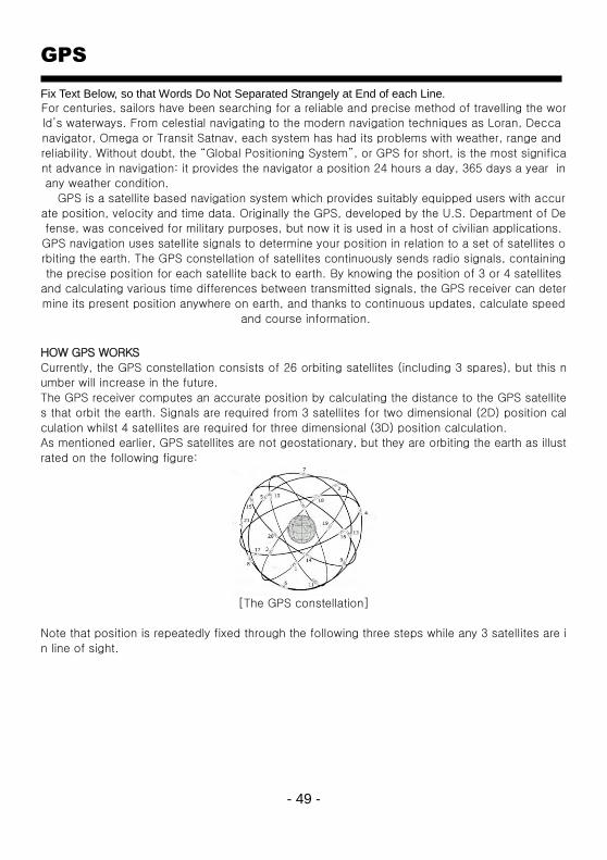
Currently, the GPS constellation consists of 26 orbiting satellites (including 3 spares), but this n
umber will increase in the future.
The GPS receiver computes an accurate position by calculating the distance to the GPS satellite
s that orbit the earth. Signals are required from 3 satellites for two dimensional (2D) position cal
culation whilst 4 satellites are required for three dimensional (3D) position calculation.
As mentioned earlier, GPS satellites are not geostationary, but they are orbiting the earth as illust
rated on the following figure:
[The GPS constellation]
Note that position is repeatedly fixed through the following three steps while any 3 satellites are i
n line of sight.

- 50 -
The position calculation procedure is indicated in the following three steps:
1. GPS satellites continuously transmit their own precise orbital data and the GPS receiver comp
utes their locations by receiving this data.
2. In this receiving process, the GPS receiver measures very accurate distances to the satellites,
using the "Spread Spectrum Modulation" method. Excellence in GPS's position-fixing accuracy
is mainly due to this technology.
3. When the satellite locations and their distances are known, the GPS receiver fixes its own pos
ition by triangulation:
[The GPS position calculation]
As illustrated in the previous figure, the position is calculated as the meeting point of three
spheres, which are drawn around the three satellites with diameters d1, d2 and d3.
Position Fixing Accuracy: HDOP
The GPS fix accuracy is due to the locations of 3 satellites in the sky. High accuracy is obtainabl
e when the satellites are widely scattered in the sky; on the
contrary, accuracy is reduced when the satellites have gathered in a narrow space. In the followi
ng figure, in both cases it is possible to obtain the GPS fix, but in the left case the accuracy will
be higher than the right:
[HDOP]
The index for position-fixing accuracy is called HDOP ("Horizontal Dilution Of Precision"). The s
maller the HDOP value, the more accurately the position can be fixed.
- 51 -
GPS
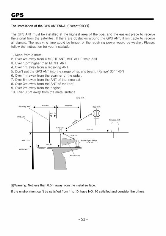
The installation of the GPS ANTENNA. (Except 95CPi)
The GPS ANT must be installed at the highest area of the boat and the easiest place to receive
the signal from the satellites. If there are obstacles around the GPS ANT, it isn't able to receive
all signals. The receiving time could be longer or the receiving power would be weaker. Please,
follow the instruction for your installation.
1. Keep from a metal.
2. Over 4m away from a MF/HF ANT, VHF or HF whip ANT.
3. Over 1.5m higher than MF/HF ANT.
4. Over 1m away from a receiving ANT.
5. Don't put the GPS ANT into the range of radar's beam. (Range: 30°~40°)
6. Over 1m away from the scanner of the radar.
7. Over 5m away from the ANT of the Inmarsat.
8. Over 3m away form the ANT of the roof.
9. Over 2m away from the engine.
10. Over 0.5m away from the metal surface.
※Warning: Not less than 0.5m away from the metal surface.
If the environment can't be satisfied from 1 to 10, have NO. 10 satisfied and consider the others.
- 52 -
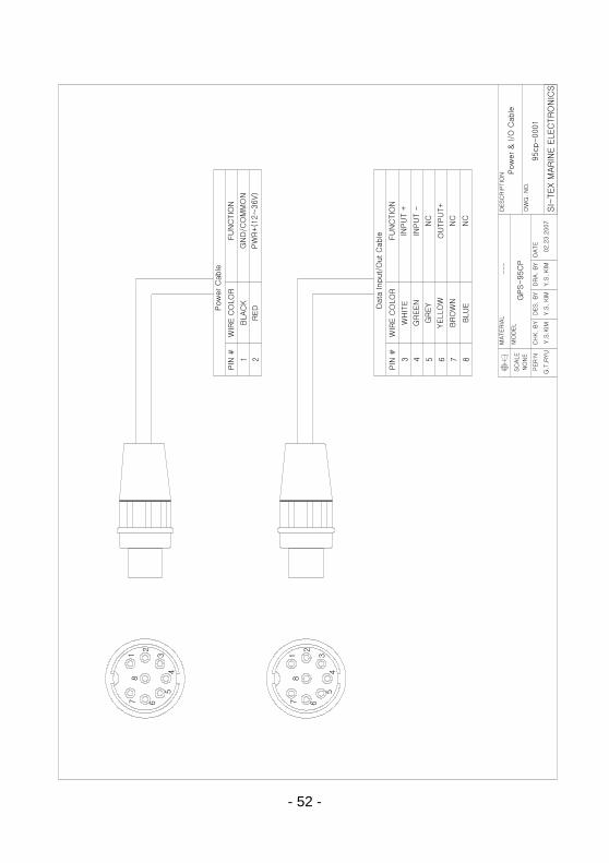
DESC
RIP
TIO
N
DW
G.
NO
.
DES.
BY
NO
NE
SC
ALE
PER
'N
MO
DEL
CH
K.
BY
MATER
IAL
DR
A.
BY
---
Y.S
. KIM
SI-
TEX M
AR
INE E
LEC
TR
ON
ICS
DATE
02.2
3.2
007
GPS-95C
P
Y.S
.KIM
Pow
er
& I/O
Cable
95cp-0001
Y.S
. KIM
G.T
.RYU
Pow
er
Cable
PIN
#W
IRE C
OLO
RFU
NC
TIO
N
1 2
BLAC
K
RED D
ata
Input/
Out C
able
PIN
#W
IRE C
OLO
RFU
NC
TIO
N
3 4 5 6 7 8
WH
ITE
GR
EEN
GR
EY
YELLO
W
BR
OW
N
BLU
E
GN
D/C
OM
MO
N
PW
R+(1
2~
36V)
7 6
54
3
2
18
7 6
54
3
2
18
INPU
T +
INPU
T -
NC
OU
TPU
T+
NC
NC

- 53 -

- 54 -
DESC
RIP
TIO
N
DW
G.
NO
.
DES.
BY
NO
NE
SC
ALE
PER
'N
MO
DEL
CH
K.
BY
MATERIA
L
DRA. B
Y
---
GPS A
NT
IS,C
HO
ISIT
EX M
AR
INE E
LEC
TR
ON
ICS
DATE
08.1
5.2
003
GPS-95C
P
H.S
.KIM
IS,C
HO
IG
.T.R
YU
95C
P 0
003
To 9
5C
P
REAR
BN
C C
ON
NEC
TO
R

- 55 -
DESC
RIP
TIO
N
DW
G.
NO
.
DES.
BY
1:1
SC
ALE
PER
'N
MO
DEL
CH
K.
BY
MATER
IAL
DR
A.
BY
---
Outlin
e a
nd d
mensio
ns
Y.S
. KIM
SIT
EX M
AR
INE E
LEC
TR
ON
ICS
DATE
02.2
1.2
007
GP-95C
P &
GP-95C
Pi
Y.S
.KIM
A4.3
-1003
Y.S
. KIM
G.T
.RYU

- 56 -
CERTIFICATE OF LIMITED WARRANTY
Providing you present a valid proof of purchase, SI-TEX Marine Electronics
Inc. warrants all parts of each new product against defects in material and
workmanship under normal use and will repair or exchange any parts proven
to be defective at no charge for a period of two years for parts and one year
for labor from the date of purchase, except as provided below under Limited
Warranty Exceptions.
Defects will be corrected during normal working hours by an authorized SI-
TEX Marine Electronics Inc. dealer, service center, or at the SI-TEX office in
St. Petersburg, Florida. There will be no charge for labor for a period of one
year from the date of purchase, except as provided below under Limited
Warranty Exceptions.
This Warranty and Proof of Purchase must be made available to the
authorized SI-TEX Marine Electronics Inc. service location or dealer at the
time of service.
LIMITED WARRANTY EXCEPTIONS
SI-TEX Marine Electronics Inc. will not be responsible for equipment which
has been subjected to water or lightning damage, accident, abuse, or
misuse, nor any equipment on which the serial number label has been
removed, altered or mutilated.
SI-TEX Marine Electronics Inc. assumes no responsibility for damage
incurred during installation.
This Limited Warranty is effective only with respect to the original purchaser.
Any cost associated with transducer replacement, other than the cost of the
transducer itself, is specifically excluded from this Limited Warranty.
Travel costs incurred will not be accepted for SI-TEX Marine Electronics Inc.
products.
THERE ARE NO WARRANTIES, WHICH EXTEND BEYOND THE DESCRIPTION
OF THE FACE HEREOF.
- 57 -
SPECIFIC EXCLUSIONS
Charges for overtime, stand-by, holiday, and per diem are specifically excluded from
the Limited Warranty.
Chart paper, stylus, stylus belt, lamps, and fuses are consumable items and are not
covered by this Limited Warranty.
Installation workmanship or materials except as provided directly by SI-TEX Marine
Electronics Inc. are not covered by this Limited Warranty. SI-TEX Marine Electronics
Inc. equipment or parts thereof, which have been repaired or altered except by an
authorized
SI-TEX Marine Electronics Inc. dealer or service center, are not warranted in any
respect.
Transducer, software update, battery, microphone, magnetron, and microwave
components and water damage on water resistant VHF radio are items excluded from
the two-year warranty and are covered by warranty for a period of one year for both
parts and labor.
SI-TEX Marine Electronics Inc. will not, at any time, assume any costs or labor
charges for checkout or external line fuse replacement or problems not found to be at
fault in equipment itself.
THERE ARE NO WARRANTIES OR GUARANTEES EXPRESSED OR IMPLIED WHICH
EXTEND BEYOND THE DESCRIPTION ON THE FACE HEREOF, INCLUDING
WARRANTIES OF FITNESS FOR A PARTICULAR PURPOSE AND MERCHANTABILITY.
SI-TEX MARINE ELECTRONICS INC. HAS NO OTHER LIABILITY TO PURCHASE FOR
DIRECT OR CONSEQUENTIAL DAMAGE OR ANY THEORY INCLUDING ABSOLUTE
LIABILITY, TORT, OR CONTRACT. THIS LIMITED WARRANTY CANNOT BE ALTERED
OR MODIFIED IN ANY WAY AND SHALL BE INTERPRETED IN ACCORDANCE WITH
THE LAWS OF THE STATE OF FLORIDA. THIS WARRANTY IS LIMITED TO THE
CONTINENTAL U.S.A., ALASKA, HAWAII, AND CANADA.
HOW TO OBTAIN SERVICE UNDER THIS WARRANTY To provide better flexibility, SI-TEX Marine Electronics Inc. gives you the option of
obtaining service under this warranty by either:
a) Contacting an authorized SI-TEX Marine Electronics Inc. service station (The
closest service station may be found by contacting your dealer of purchase.)
Or
b) Shipping your equipment prepaid via UPS or truck with insurance prepaid to SI-
TEX Marine Electronics Inc. at the address provided below. SI-TEX Marine
Electronics Inc. will, whenever possible, make all repairs covered by Limited Warranty
within two weeks of receiving the equipment in Florida and return same to you, freight
prepaid.
c) You must present a copy of your Purchase Sales Slip at the time you request
warranty service.

- 58 -
Shipping/Mailing Address:
SI-TEX Marine Electronics Inc.
11001 Roosevelt Blvd., Suite 800
St. Petersburg, FL 33716
727-576-5734
SI-TEX Marine Electronics Inc. offers a complete line of quality marine electronics
including fishfinders, electronic charting systems, radars, autopilots,
GPS/WAAS/Loran receivers, SSB receivers, direction finders, VHF/FM
radiotelephones and integrated systems. For more information, contact your SI-TEX
dealer or the main office, located in St. Petersburg, Florida.