gps transmitter and receiver system for navigation and...
TRANSCRIPT

I J C T A, 9(2) 2016, pp. 505-511© International Science Press
1 Research Scholar, Department of ECE, Birla Institute of Technology, Mesra, (Deogarh Campus), Jharkhand, INDIA, E-mail:[email protected]
2 HOD, Department of ECE, Birla Institute of Technology, Mesra, (Deogarh Campus), Jharkhand, INDIA, E-mail: [email protected]
GPS Transmitter and Receiver System forNavigation and location Based ServicesRachna Kumari1 and Mainak Mukhopadhyay2
ABSTRACT
The proposed research is described to show design and implementation of the Global Positioning System (GPS)transmitter and receiver system for real time navigation, location based services and last but not least trackingapplications. This GPS system measures the various satellite position located in space and some navigationalparameters such as position of the object/satellite on world latitude or longitude, velocity, altitude and the mostimportant, name of current location etc. This research system is used for providing information on the topic of thesatellites that are view in provisions the number of satellites are being tracked, the satellite ID/PRN (Pseudo RandomNoise) and parameters like Signal to Noise Ratio (SNR) of the capture satellite signal. Every model and informationis described above on the Simulation and Graphical User Interface (GUI). To complete this research we are followingthe Matlab and Simulink with DSP, Xilinx Software.
Keywords: Global Positioning System; DSP; Graphical User Interface; Simulink; Xilinx Software.
I. INTRODUCTION
The Global Positioning System (GPS) [1] system is space based satellite navigation system. In space 32satellite are there to provide acquire signal information to the GPS receiver but we have design our modelusing the 29 satellite which mean we have counted 29 satellite ID/PRN code in space. Whenever foroperating a GPS receiver requires minimum four satellites to acquire the signal information. GPS receiversare used to determine the current location at real transmission time, velocity and signal speed depend onspeed of light (3 x 10⁸ meters/second) in all weather conditions [2, 14]. It is easily reached to anyone andfreely accessible for tracking a location and calculates a real time user position. GPS Satellite signals areused for broadcasting on equivalent frequencies but it works on diverse ranging codes having low crosscorrelation. The satellites signal are having a CDMA (Code Division Multiple Access) for ranging codes toestimate the propagation as well as navigation time and to calculate the exact position of the satellite andreal transmission time [11].
GPS receiver uses such type of ranging code like P(Y) code for military purpose and C/A codes (coarseacquisition code), these codes are used basically for satellite broadcasting. Every code has a unique valuewhich is called the signal frequency such as C/A code is of 1.023 MHz and the carrier frequency of L1signal is 1575.42 MHz. The coarse acquisition code was provided by GPS satellites system [3]. It is generatedas a sequence of 1023 chips. It is repeated every milli second with chipping rate of 1.023 MHz and modulatedonly on L1 frequency. Here used a simulation environment such Simulink 8.1 to simulate and verify eachphase of C/A code. A complete C/A code was built in simulation using received satellite ID/PRN code,initial code phase and loaded code phase, these all are required in the C/A code generation [4]. PRN codeis abbreviated as pseudo random noise code which is determined for 29 satellites. This code determines theC/A code replica of different 1023 chips using a shift register. It is compared with the satellite code using a
506 Rachna Kumari and Mainak Mukhopadhyay
correlator [16]. A complete GPS system has main three section transmitter, receiver and channel. Thesimulation model and result of these three sections are given below.
II. LITERATURE REVIEW
Traditional methods of surveying and navigation resort to tedious field and astronomical observation forderiving positional and directional information [5, 6]. Diverse field conditions, seasonal variation andmany unavoidable circumstances always bias the traditional field approach. However, due to rapidadvancement in electronic systems, every aspect of human life is affected to a great deal. Field of surveyingand navigation is tremendously benefited through electronic devices. Many of the critical situations insurveying/navigation are now easily and precisely solved in short time (Seeber, Gunter 2003) [12].
Although the speciûc requirements vary signiûcantly, the most fundamental aspects remain unchanged.Every GPS application ultimately involves the determination of platform position, velocity, and/or time [7,8]. The exact algorithms and implementations differ depending upon the application but in each case themost basic measurements are the same: user-to-satellite Line-of-Sight (LoS) range and range-rate. Informationdescribing the satellite position and velocity is also required. This is transmitted to the user in the form ofbinary data over the ranging signal via a spread-spectrum communication technique (R. Ziemer and R.Peterson, 1985) [13].
When the locally generated code is locked to the received code, the correlation effectively ampliûes theunderlying BPSK data signal. The ampliûcation factor is given by, the length of the PRN sequence. The noencrypted portion of the GPS signal employs spreading codes known as Gold codes (R. Gold, 1967) [15].The Gold codes are formed by combining two -sequences. The result is a family of PRN codes with lowcross correlation between codes. This allows all satellites to transmit on the same carrier frequency withoutincurring signiûcantly mutual interference. The encrypted portion of the GPS signal also uses quasi orthogonalcodes, but they are not Gold codes. Since each satellite is assigned a unique code, the system is referred toas code-division multiple access (CDMA) [9, 10].
III. PROPOSED METHODOLOGY
This Simulation stages and implementation of the GPS transmitter and receiver system having afunctionality such as transmitter input, transmitter model, channel that connect transmitter signal outputto direct or bypass to the receiver input and navigation of GPS receiver on a DSP/Xilinx system usingthe graphical programming language, C/C++ Programming. This Structural design makes every sectionof the GPS receiver very easy to understand, the DSP environment is used with approach simulation aswell as implementation stages. The implementation stages are easy to understand the functionalityas compared to the developing stages of most of the designer. It has a new look for designing,simulating, implementing and developing the most difficult parts of a representative GPS transmitterand receiver.
(A) Trasmitter of GPS System
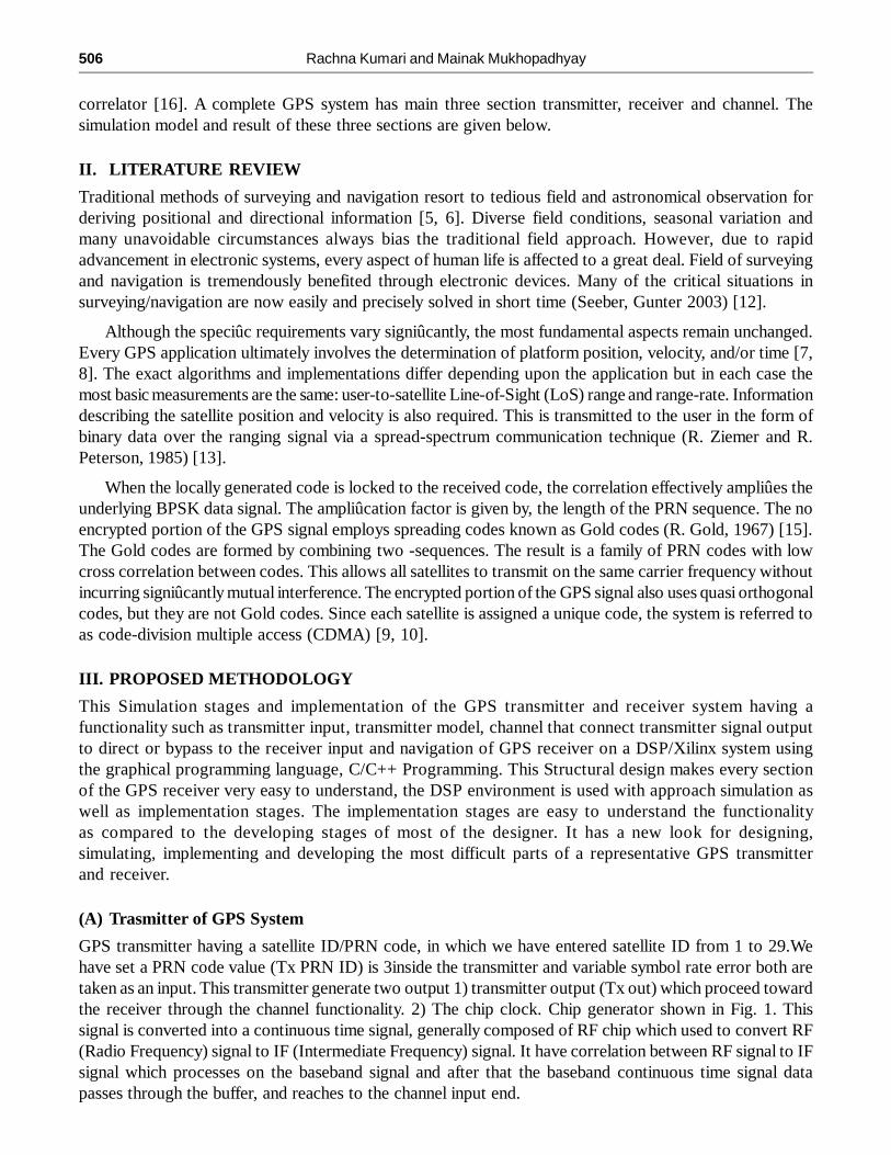
GPS transmitter having a satellite ID/PRN code, in which we have entered satellite ID from 1 to 29.Wehave set a PRN code value (Tx PRN ID) is 3inside the transmitter and variable symbol rate error both aretaken as an input. This transmitter generate two output 1) transmitter output (Tx out) which proceed towardthe receiver through the channel functionality. 2) The chip clock. Chip generator shown in Fig. 1. Thissignal is converted into a continuous time signal, generally composed of RF chip which used to convert RF(Radio Frequency) signal to IF (Intermediate Frequency) signal. It have correlation between RF signal to IFsignal which processes on the baseband signal and after that the baseband continuous time signal datapasses through the buffer, and reaches to the channel input end.
GPS Transmitter and Receiver System for Navigation and Location based Services 507
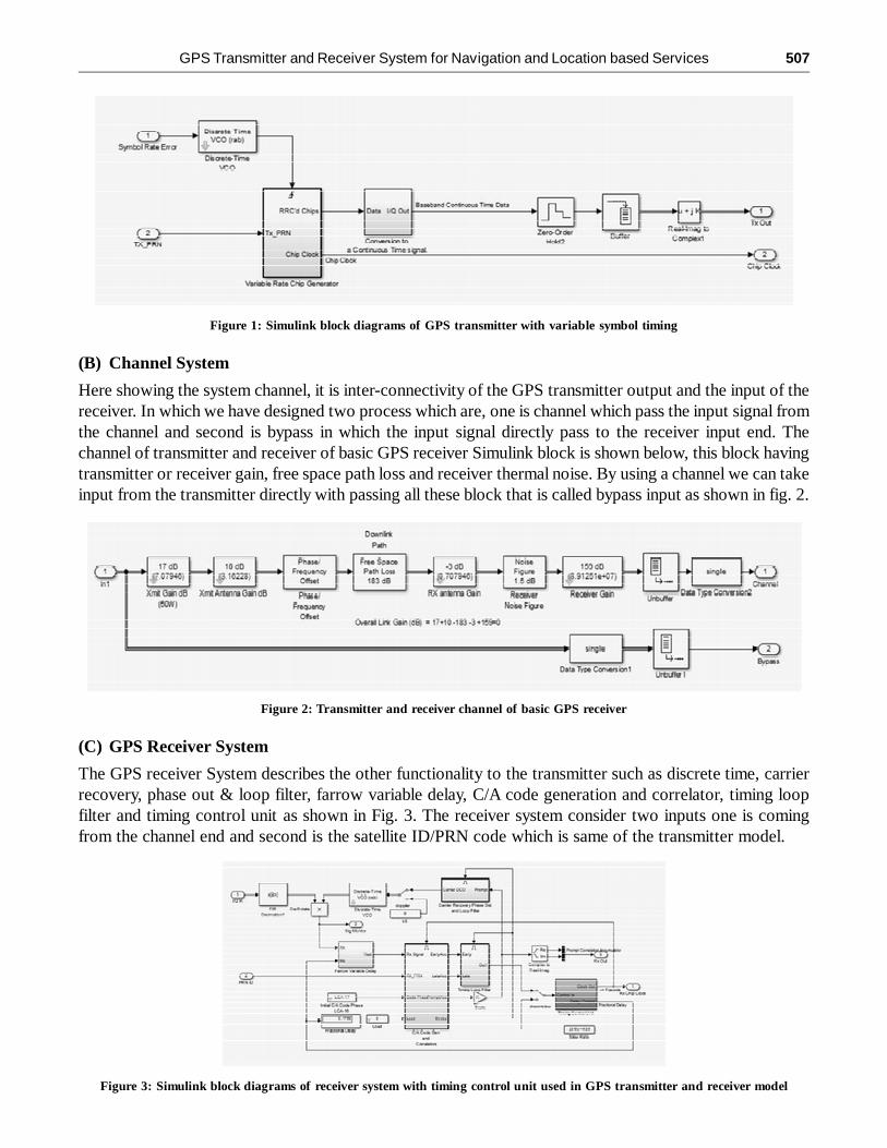
(B) Channel System
Here showing the system channel, it is inter-connectivity of the GPS transmitter output and the input of thereceiver. In which we have designed two process which are, one is channel which pass the input signal fromthe channel and second is bypass in which the input signal directly pass to the receiver input end. Thechannel of transmitter and receiver of basic GPS receiver Simulink block is shown below, this block havingtransmitter or receiver gain, free space path loss and receiver thermal noise. By using a channel we can takeinput from the transmitter directly with passing all these block that is called bypass input as shown in fig. 2.
Figure 1: Simulink block diagrams of GPS transmitter with variable symbol timing
Figure 2: Transmitter and receiver channel of basic GPS receiver
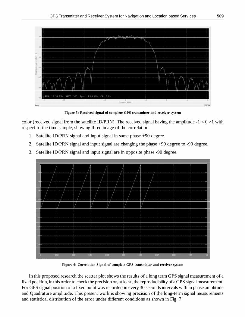
(C) GPS Receiver System
The GPS receiver System describes the other functionality to the transmitter such as discrete time, carrierrecovery, phase out & loop filter, farrow variable delay, C/A code generation and correlator, timing loopfilter and timing control unit as shown in Fig. 3. The receiver system consider two inputs one is comingfrom the channel end and second is the satellite ID/PRN code which is same of the transmitter model.
Figure 3: Simulink block diagrams of receiver system with timing control unit used in GPS transmitter and receiver model

508 Rachna Kumari and Mainak Mukhopadhyay
The input signal of the GPS is passing through the farrow variable delay Simulink block and reaches tothe C/A code generator. The correlator block correlated the input and output signal and generate a waveformthat shows the behavior of the input and output. The block C/A code generator and correlator for thereceiver signal are generate a C/A code chip size is 1.023. In this model we have add two new Simulinkblock one is timing loop filter and second is the timing control unit. The timing loop filter measures thereceiver signal in account to time dependence and plot the early or late receiver signal. Timing control unitis used in GPS receiver signal model for controlling the clock time and maintained delay signal time.
IV. EXPERIMENTAL RESULT
The results of GPS transmitter and receiver system are showing the receiver spectrum, scatter plot, correlationand power estimation. These all block are taking the output from the receiver block. Here, the completetransmitter and receiver of the GPS as shown in Fig. 4. and receiver spectrum block, correlator block andpower estimation is clearly mentioned in this block.
Figure 4: Simulink block diagrams of complete GPS transmitter and receiver system.
The receiver spectrum is monitor of the GPS receiver signal with is the combination of the transmitterpasses signal and satellite ID/PRN code generated signal. The receiver spectrum signal has generatedfollowing parameters values given below:
• Resolution Bandwidth (RBW) = 11.99 KHz
• NFFT = 513
• Span = 4.09 MHz
• Carrier Frequency (CF) = 0 Hz
The received signal spectrum is showing the signal with respect to frequency and magnitude, thehorizontal axis shows the frequency value of the signal and vertical axis shows the magnitude value of thereceived signal as shown in Fig. 5.
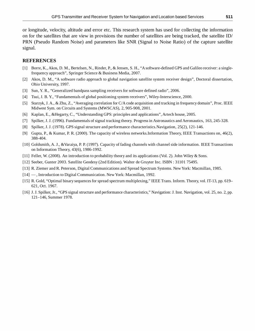
The Correlation between the Satellite ID/PRN received signal and input signal come through the channelwhich passes by the transmitter including sample frequency (Fs= 8*1.023 MHz or 8*C/A chip Size). InFig. 6 two signals is showing: 1). Magenta color (input signal including sample frequency) and 2) yellow
GPS Transmitter and Receiver System for Navigation and Location based Services 509
color (received signal from the satellite ID/PRN). The received signal having the amplitude -1 < 0 >1 withrespect to the time sample, showing three image of the correlation.
1. Satellite ID/PRN signal and input signal in same phase +90 degree.
2. Satellite ID/PRN signal and input signal are changing the phase +90 degree to -90 degree.
3. Satellite ID/PRN signal and input signal are in opposite phase -90 degree.
Figure 5: Received signal of complete GPS transmitter and receiver system
Figure 6: Correlation Signal of complete GPS transmitter and receiver system
In this proposed research the scatter plot shows the results of a long term GPS signal measurement of afixed position, in this order to check the precision or, at least, the reproducibility of a GPS signal measurement.For GPS signal position of a fixed point was recorded in every 30 seconds intervals with in phase amplitudeand Quadrature amplitude. This present work is showing precision of the long-term signal measurementsand statistical distribution of the error under different conditions as shown in Fig. 7.

510 Rachna Kumari and Mainak Mukhopadhyay
In the present GPS system we have calculated some error like phase error, integrator and carrier VCO.The graph of these error in Fig. 8 having zero amplitude with respect to time sample value at infinite runtime.
Figure 7: Scatter plot of complete GPS transmitter and receiver system
Figure 8: Errors measurement in the complete GPS transmitter and receiver system
V. CONCLUSION
In the proposed research we introduced the simulation and implementation of GPS transmitter and receiveron the DSP/Xilinx System through a graphical programming language (Simulink 8.1). Here we havecompleted an idea of modifying both the IF and Fs in input side of the GPS receiver and the subsequentresults obtained from the PRN code at set value 3. GPS system is measures various satellite positionlocated in the space and showing the exact position of the satellite with the help of the scatter plot. Here wehave calculated the value of navigational parameters such as position of the satellite on the world latitude
GPS Transmitter and Receiver System for Navigation and Location based Services 511
or longitude, velocity, altitude and error etc. This research system has used for collecting the informationon for the satellites that are view in provisions the number of satellites are being tracked, the satellite ID/PRN (Pseudo Random Noise) and parameters like SNR (Signal to Noise Ratio) of the capture satellitesignal.
REFERENCES[1] Borre, K., Akos, D. M., Bertelsen, N., Rinder, P., & Jensen, S. H., “A software-defined GPS and Galileo receiver: a single-
frequency approach”, Springer Science & Business Media, 2007.
[2] Akos, D. M., “A software radio approach to global navigation satellite system receiver design”, Doctoral dissertation,Ohio University, 1997.
[3] Sun, Y. R., “Generalized bandpass sampling receivers for software defined radio”, 2006.
[4] Tsui, J. B. Y., “Fundamentals of global positioning system receivers”, Wiley-Interscience, 2000.
[5] Starzyk, J. A., & Zhu, Z., “Averaging correlation for C/A code acquisition and tracking in frequency domain”, Proc. IEEEMidwest Sym. on Circuits and Systems (MWSCAS), 2, 905-908, 2001.
[6] Kaplan, E., &Hegarty, C., “Understanding GPS: principles and applications”, Artech house, 2005.
[7] Spilker, J. J. (1996). Fundamentals of signal tracking theory. Progress in Astronautics and Aeronautics, 163, 245-328.
[8] Spilker, J. J. (1978). GPS signal structure and performance characteristics.Navigation, 25(2), 121-146.
[9] Gupta, P., & Kumar, P. R. (2000). The capacity of wireless networks.Information Theory, IEEE Transactions on, 46(2),388-404.
[10] Goldsmith, A. J., &Varaiya, P. P. (1997). Capacity of fading channels with channel side information. IEEE Transactionson Information Theory, 43(6), 1986-1992.
[11] Feller, W. (2008). An introduction to probability theory and its applications (Vol. 2). John Wiley & Sons.
[12] Seeber, Gunter 2003. Satellite Geodesy (2nd Edition). Walter de Gruyter Inc. ISBN : 31101 75495.
[13] R. Ziemer and R. Peterson, Digital Communications and Spread Spectrum Systems. New York: Macmillan, 1985.
[14] — , Introduction to Digital Communication. New York: Macmillan, 1992.
[15] R. Gold, “Optimal binary sequences for spread spectrum multiplexing,” IEEE Trans. Inform. Theory, vol. IT-13, pp. 619–621, Oct. 1967.
[16] J. J. Spilker, Jr., “GPS signal structure and performance characteristics,” Navigation: J. Inst. Navigation, vol. 25, no. 2, pp.121–146, Summer 1978.