gps/imu navigation and simulation for higher-than … navigation and simulation for higher-than-gps...
TRANSCRIPT

GPS/IMU Navigation and Simulation for Higher-Than-GPS Orbits
Kenn Gold and Alison Brown, NAVSYS Corporation
BIOGRAPHY
Kenn Gold is the Vice President of Engineering of at NAVSYS Corporation and the Product Area Manager for the Advanced Systems and Simulation Tools group. His work includes development of spaceborne GPS receivers, integrity monitoring algorithm development, and GPS simulator design. He holds a PhD from University of Colorado in Aerospace Engineering. Alison Brown is the President and Chief Executive Officer of NAVSYS Corporation. She has a PhD in Mechanics, Aerospace, and Nuclear Engineering from UCLA, an MS in Aeronautics and Astronautics from MIT, and an MA in Engineering from Cambridge University. In 1986, she founded NAVSYS Corporation. Currently, she is a member of the Air Force C2ISR Center Advisory Group, the Interagency GPS Executive Board Independent Advisory Team (IGEB IAT), and an Editor of GPS World Magazine. She is an ION Fellow and was inducted into the SBA “Wall-of-Fame” in 2003.
ABSTRACT
NAVSYS Corporation has modified its software GPS receiver (SGR) and built an engineering development unit of the High-gain Advanced GPS Receiver (HAGR) optimized for GPS tracking in an orbital environment. Enhancements to the SGR include the ability to track both direct GPS signals, as well as weaker GPS sidelobes. This requires digital beam steering and beam nulling to increase gain towards the weaker signals, while partially nulling direct lobe signals to achieve signal strength balancing. The space based SGR approach also makes use of inertial aiding data to allow continuous navigation through high dynamic mission phases such as launch, or orbit transfer. Goddard Space Flight Center´s GEONS navigation software has also been integrated with the SGR to allow for real time onboard navigation. To test the engineering development unit, significant enhancements were made to the NAVSYS Advanced GPS Hybrid Simulator (AGHS) to allow simulation in an orbital environment. The AGHS is driven by Matlab and can receive trajectory information in real time from Satellite Tool Kit or other commercial-off-the-shelf or government-off-the-shelf profile generation software. The simulator also contains a Digital Storage Receiver (DSR)
capable of recording live GPS data from complicated RF environments (such as urban canyon or indoor GPS) for later playback with an RF Modulator, or that can be played back directly into a digital GPS receiver. The capabilities offered by the AGHS substantially enhance the utility of GPS simulation. Additionally, a capability to simulate inertial measurement unit (IMU) data simultaneously with the GPS and from the same input trajectory has been added. The simulator is useful in testing and developing next generation receiver and navigation which will utilize coupled GPS/inertial navigation scenarios. The AGHS is capable of simulating 12 GPS satellites in 8 RF channels. The RF channels of the AGHS are fully coherent, allowing for GPS wavefront simulation. IMU measurement data coherent in time with the GPS data is generated at a rate of up to 400 Hz. Simulation and tracking results will be shown for various orbital scenarios. Orbital platform simulation and tracking results will be shown for highly eccentric orbits, in which GPS tracking of side lobes of satellites on the other side of the Earth are achieved.
INTRODUCTION
NAVSYS has developed the design for a flexible, high-performance Space-based Software GPS Receiver (SSGR) and is currently building an Engineering Development Unit (EDU) to demonstrate the next generation capabilities of the SSGR for space applications. The SSGR will provide an integrated precision navigation and attitude determination solution for space applications including Low Earth Orbit (LEO), Highly Eccentric Orbit (HEO), and Geostationary Earth Orbit (GEO) missions. The ability to track low power GPS satellites will extend the use of GPS for precision navigation and timing, particularly for high altitude space missions (above the GPS satellite constellation). The SSGR will be suitable for supporting multiple space missions including GPS metric tracking during launch, orbit determination during transfer to geostationary orbits, and high accuracy navigation, attitude control, and timing. The flexibility of the SSGR design will allow it to be reprogrammed for use in launch and orbit entry, station keeping, and autonomous orbit estimation applications. One of the biggest challenges of designing a space-based GPS receiver is testing, since the dynamics involved are

radically different from anything achievable on the ground. Commercially available GPS simulators that can simulate the space environment are very expensive, generally have high learning curves, and are limited in capability. The multi-element AGHS designed by NAVSYS addresses many of these concerns and will, therefore, be used to test performance of the SSGR design. AGHS generates simulated digital signal sets using profiles generated by NAVSYS’ MATLAB® Signal Simulation capability and can be used to generate digital representations for the GPS signals under the various scenarios for playback either into an RFM or directly into the GPS receiver. The NAVSYS MATLAB® Toolbox has been augmented with many new tools to allow easy simulation of various space-based mission profiles. The added simulation scenarios cover the different phases of a space mission as mentioned above. New toolbox features include functions to determine the visibility and expected signal strength of GPS signals that will be received in each scenario and the ability to drive AGHS under each of these scenarios. Orbit and attitude information is easily entered into the
tool via a text-based file, which can be generated with Satellite Tool Kit or other similar tools.
MISSION PHASES OF INTEREST
The SSGR design has been optimized to address the various complications of space-based GPS usage. The receiver must have the capability to maintain lock through dynamic maneuvers; both during launch and orbit transitions. GPS visibility must be maintained even for spinning satellites and when the satellite is in higher orbit than GPS orbit. The use of beam steering and the addition inertial data to aid the GPS tracking and recovery during outages gives the receiver the ability to maintain lock in such situations. The Digital Beam Steering (DBS) capability utilized in the SSGR allows for the construction of a composite GPS signal from multiple non-coplanar antenna elements placed around the spacecraft. The beam steering/null forming functionality also allows for tracking of weak GPS signals (such as GPS sidelobes) from higher than GPS orbit. Table 1 summarizes the enhancements that will be required for the SSGR and the benefits that will be gained in each mission phase.
Table 1 Benefits Gained in Various Mission Phases
Mission/ Capability
Launch & Orbit Entry Station-keeping Formation-Flying Recovery &
Landing
3-D Beam-steering
Maintains SV visibility at all attitudes
Provides gain towards GPS SVs
Provides gain towards GPS SVs
Maintains SV visibility at all attitudes
Inertial-aiding
High dynamic aided tracking for data continuity and navigation through SV outages
N/A N/A
High dynamic aided tracking for data continuity and navigation through SV outages
Precision GPS Navigation
Provides high accuracy code/carrier observations for Wide Area Differential GPS (WADGPS) solution
Provides high accuracy code/carrier observations for WADGPS solution
Provides high accuracy code/carrier observations for Kinematic GPS (KGPS) solution
Provides high accuracy code/ carrier observations for WADGPS and KGPS solution
Attitude Determination N/A
Provides interferometric attitude data from array
Provides interferometric attitude data from array
N/A

HIGH-GAIN ADVANCED GPS RECEIVER
NAVSYS’ HAGR[1] is a software reprogrammable, digital beam steering GPS receiver. The HAGR components are illustrated in Figure 1. With the HAGR digital beam steering implementation, each RF input from an antenna element is converted to a digital signal using a Digital Front-End (DFE). The HAGR can be configured to operate with up to sixteen antenna elements (L1 and L2), with the antenna elements installed in any user-specified antenna array pattern. Each DFE board in the HAGR can convert signals from eight antenna elements. The digital signals from the DFE modules are then provided to the HAGR digital signal processing cards. The HAGR can be configured to track up to twelve satellites providing L1 C/A and L1/L2 P(Y) observations when operating in the keyed mode. The digital signal processing is performed in firmware downloaded from the host computer. Since the digital spatial processing is unique for each satellite channel, the weights are optimized for the particular satellites being tracked. The digital architecture allows the weights to be computed in the HAGR software, then downloaded and applied pre-correlation to create a digital adaptive antenna pattern to optimize the signal tracking performance.
DFEModule
DFEModule
DFEModule
DFEModule
LocalOscillator
To All Modules
Sample Clock and Reference Clock to AllCircuits
Array Weights
Logic
CorrelatorLogic
CalibrationLogic
Processing
ProcessingChannel
Up to 16 AntennaElements
AntennaElement
Output Bus
6 to 12 ProcessingChannels
ControlComputer
I/QData
Weights &CorrelatorControl
AttitudeSensorC
Processing Channel
NB
Channel
Figure 1 P(Y) HAGR System Block Diagram
SOFTWARE GPS RECEIVER ARCHITECTURE
The flexible Software GPS Receiver (SGR) architecture leveraged by the HAGR allows the GPS signal processing software and firmware to be easily ported to run on space-qualified signal processing and host computer cards. The GPS software radio architecture adopted by the HAGR (shown in Figure 2) allows the receiver configuration to be optimized depending on the phase of flight. For example, different antenna inputs and navigation modes could be used during launch and orbit entry than during the remaining mission life where the receiver could be
optimized for autonomous orbit estimation and station-keeping. The software reprogrammable GPS approach can be implemented on radiation hardened signal processors and reused during the mission life to support multiple mission requirements.
DIGITAL BEAM STEERING
The SSGR architecture utilizes 4π steridian field of view using 3-D digital beam steering. This provides continuous tracking during maneuvers while simplifying antenna installation through the use of a digital interface to combine the signals from the multiple antennas into a single composite signal. Digital beam steering provides additive gain in the direction of the GPS satellite tracked, improving signal reception at high altitude orbits (e.g. transfer orbits or GEO). Digital beam steering can also provide antenna directivity towards both the GPS satellite main lobes and side lobes, increasing the numbers of satellites that can be tracked. Modular digital beam steering architecture can be configured for cross-strapping to provide added redundancy.
I/O(Serial)
Antenna
DFE
Reference andLO
Host ComputerCAC
(Xilinx)DBS
2 to 24MHz
bandwdth
SampledRF
Spectrum
Digital Receiver
I & QData
Control
ReceiveSignals
PhaseCoherent
DownConversion
InternalTime
Synch.
Beam Steering
Track Satellites
BasebandProcessing
Loop Control
Calibration
NetworkConnectivity
Security
Correlation
HA
GR
Fu
nct
ion
s
Figure 2 NAVSYS Software GPS Receiver Architecture
The digital signal from each of the HAGR antenna elements can be described by the following equation.
∑ ∑= =
++=Ns
i
Nj
kkjkkik txjtntxsty
1 1
),()(),()(
where si(xk,t) is the ith GPS satellite signal received at the kth antenna element nk(t) is the noise introduced by the kth DFE jj (xl,t) is the filtered jth jammer signal received at the kth antenna element
The GPS satellite signal at each antenna element (xk) can be calculated from the following equation.
sikikTiiki etsxitstxs ),0()1
2exp{),0(),( =−=
λπ
where si(0,t) is the satellite signal at the array center and 1i is the line-of-sight to that satellite esik are the elements of a vector of phase angle offsets for satellite i to each element k The combined digital array signal, z(t), is generated from summing the weighted individual filtered DFE signals. This can be expressed as the following equation.
++′=′= ∑ ∑
= =
Ns
i
Nj
ljljsii etjtnetswtywtz
1 1
)()()()()(
With beam steering, the optimal weights are selected to maximize the signal/noise ratio to the particular satellite being tracked. These are computed from the satellite phase angle offsets as shown in the following equation.
s
MTi
Ti
BS e
xi
xi
w =
−
−
=
)12
exp{
.
)12
exp{ 1
λπ
λπ
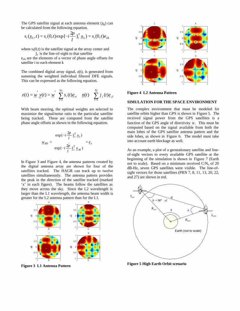
In Figure 3 and Figure 4, the antenna patterns created by the digital antenna array are shown for four of the satellites tracked. The HAGR can track up to twelve satellites simultaneously. The antenna pattern provides the peak in the direction of the satellite tracked (marked ‘x’ in each figure). The beams follow the satellites as they move across the sky. Since the L2 wavelength is larger than the L1 wavelength, the antenna beam width is greater for the L2 antenna pattern than for the L1.
Figure 3 L1 Antenna Pattern
Figure 4 L2 Antenna Pattern
SIMULATION FOR THE SPACE ENVIRONMENT
The complex environment that must be modeled for satellite orbits higher than GPS is shown in Figure 5. The received signal power from the GPS satellites is a function of the GPS angle of directivity α. This must be computed based on the signal available from both the main lobes of the GPS satellite antenna pattern and the side lobes, as shown in Figure 6. The model must take into account earth blockage as well. As an example, a plot of a geostationary satellite and line-of-sight vectors to every available GPS satellite at the beginning of the simulation is shown in Figure 7 (Earth not to scale). Based on a minimum received C/No of 20 dB-Hz, seven GPS satellites were visible. The line-of-sight vectors for those satellites (PRN 7, 8, 11, 13, 20, 22, and 27) are shown in red.
O
d
Earth (not to scale)
αuserR
GPSR
θ
el+°= 90β
GPSxr
userxr
Figure 5 High Earth Orbit scenario

Figure 6 Modeled relative antenna attenuation of the GPS transmitting antennas
Figure 7 Line-of-sight vectors from GOES satellite to each available GPS satellite. Visible GPS satellites based on a C/No threshold of 20 dB-Hz are shown in red
MATLAB® GPS TOOLBOX
The AGHS GPS signals are generated with inputs from the NAVSYS’ MATLAB® GPS Tools. The signal flow employed in this generation process is shown in Figure 8. The MATLAB® tools allow the user to have total control over the GPS signals that are simulated. The initial simulated trajectory is input as a user defined solution/trajectory profile. The MATLAB® tools then convert this trajectory into an RNG format using the sol2rng function, which includes the pseudo-range, signal power, Doppler frequency shift and carrier phase of the simulated signals. The GPS navigation message data to be modulated on each simulated signal is generated next. The aghssim functions provide the low-level control of the signal generation.
Aghssim outputs the raw signal amplitude, code phase, and carrier phase information needed to generate the C/A and P(Y) code signals. There are two modes of operation for the aghssim functionality. The first is the software signal generation mode where the MATLAB® functions are used to directly generate a simulated Digital Signal Format (DSF) file, which is a digital representation of the GPS simulated signals. The second mode is where the Correlator Accelerator Card (CAC) is controlled through the MATLAB® drivers to generate the digital simulated signal in real-time. In either of these modes, the AGHS-generated signals can be recorded in the Digital Storage Receiver (DSR)[2] and/or modulated onto an RF carrier for output to a GPS receiver under test.
Save to Disk asDSF File
User Position(inc time)
sol2rng.m
Generate RNGdata from
trajectory inputs
SV Ephemeris
aghssim.m
Generate 1 kHzCAC Downloads(PR,CPH,D(t))
cacsig.m
Emulate CACDigital SignalGeneration
DSR
Data PlaybackDigital Output to RFM
RNG
gpsmsg.m
GenerateNavigation
Message data
RNG MSG
Figure 8 MATLAB® Signal Simulation
ADVANCED GPS HYBRID SIMULATOR
The AGHS architecture illustrated in Figure 9 has several benefits over previous analog simulators. This includes the following capabilities that are being leveraged in the SSGR test activities.

Drive A
rray(8 high-capacity drives)
DSR Computer
(runningMATLAB)
PC
I Bus
StreamStor
FPDP card
FP
DP
ethernetpackets
FlightSim Computer
ethernetraw nav data
AGHS Host Computer(SBC in cPCI chassis)
Correlator AcceleratorCard (CAC)
Digital Front EndCards (DFEs)
RF Modulator Cards(RFMs)
cPCIBus
digital data
CRPA
GPS UECRPA AE
L1/L2 in
L1/L2 out
Advanced GPS Hybrid Simulator (AGHS)
Figure 9 AGHS System Architecture
o Access to all levels of satellite signal generator control through NAVSYS’ MATLAB® satellite and signal generation scripts
o Software interface for insertion of future GPS signals or simulated jammer waveforms onto composite digital satellite signal profile
o Digital data storage for exact reconstruction and playback of signal simulation profiles
o Digital output from the simulator of pre-recorded or real-time simulated signals
o Digital tracking of the recorded signals for high-fidelity signal reconstruction and analysis
o High-fidelity, phase-coherent RF modulation of digital signals for output to a GPS receiver or multi-element Controlled Reception Pattern Antenna (CRPA).
In the profile generation mode, the AGHS system generates the satellite signal profile to be simulated. The user trajectory is input either from a pre-defined solution file (SOL) or in real time through the ethernet interface. Once the profile is defined, the AGHS system generates the digital signals that emulate the outputs from each of the SSGR Digital Antenna Elements (DAEs) that would be applied to the SSGR signal processor. This mode will run in real time and can also to be used to generate recorded data files in the DSR subsystem for playback in the SSGR. We will record data libraries for each of the mission profiles generated to allow this testing to be repeated with different software configurations of the SSGR.
In the digital signal playback mode, the data recorded in the DSF file is played into the SSGR signal processor. As an option, it can also be modulated onto an RF signal by the RFM subsystem for playback into the individual antenna elements. To support future applications involving tightly integrated GPS and inertial systems and ultra-tightly-coupled GPS/inertial receivers, AGHS has been upgraded to add inertial simulator capability. This will operate in conjunction with the AGHS satellite signal simulation capability as shown in Figure 10.
GPS Satellite SignalSimulator
UTC GPS/Inertial Systemunder test
Inertial Simulator
SimulatedTrajectory
SV Errors &Constellation
Inertial Errors
Figure 10 IMU Simulation Architecture
The IMU model component generates simulated inertial measurement unit delta-theta and delta-V inputs to the SSGR during testing. These are tightly synchronized in time to the simulated GPS data.

SATELLITE TOOL KIT INTERFACE
Satellite Tool Kit (STK) “standard” is the core of the STK software suite and it is free to all government, aerospace, and defense professionals [3]. STK provides the analytical engine to calculate data and display multiple 2-D maps to visualize various time-dependent information for satellites and other space-related objects, such as launch vehicles, missiles, and aircraft. STK's core capabilities include orbit/trajectory ephemeris generation, acquisition times, and sensor coverage analysis for any of the objects modeled in the STK environment. To extend the analytical capabilities of STK, Analytical Graphics Inc. (AGI) also offers STK Professional (STK/PRO), a collection of additional orbit propagators, attitude profiles, coordinate types and systems, sensor types, inview constraints, and city, facility, and star databases. Orbit trajectory generation is a feature included in the core STK program. The Initial orbit state can be entered in Cartesian (Earth Fixed or Inertial) coordinates or with orbit Keplerian elements. Many satellites are available in a database included with the program and others can be downloaded from the Analytical Graphics website. Several orbit integrators are available to generate the orbit trajectory from the initial state. STK provides many visualization tools which are useful in determining that an orbit has been properly generated. Figure 11 shows a ground track for the MMS satellite, which is in a highly elliptic orbit. The apogee of this orbit is higher than the orbits of the GPS satellites. Parameters for Highly-Eccentric-Orbit Satellite Propagator: TwoBody Start Time: 24 Oct 2003 11:00:00.00 UTC Stop Time: 25 Oct 2003 11:00:00.00 UTC Step size: 60 sec Orbit Epoch: 21 June 2003 00:00:00.00 UTC Semimajor Axis: 41457.00 km Eccentricity: 0.53846 Coord. Type: Classical Coord. System: J2000 Inclination: 28.5 deg Argument of Perigee: 0.0 deg RANN: 90.0 deg Mean Anomaly: 0.0 DEG STK is capable of generating a report which contains the position and velocity of a satellite at user defined time steps. Figure 12 shows a portion of the trajectory generated in the Earth Centered Earth Fixed coordinate frame at 10 sec intervals. This trajectory is used with a modified version of the sol2rng.m MATLAB® function to generate the range vectors and to drive the simulation for GPS data in orbital scenarios. Various attitude profiles are also available in the STK trajectory simulations, and attitude reports can be generated using Euler angles or
quaternions. The modified AGHS simulation profiles make use of quaternions to describe the rotation of a satellite. The quaternions define the orientation of a vector in the spacecraft body-fixed frame with respect to the Earth Centered Inertial frame. Thus, a normal vector and in plane vector for a GPS antenna, defined in the Body fixed frame, relative to the spacecraft center of mass can be rotated to inertial coordinates. The GPS ToolBox contains functions to create a direction cosine matrix for this rotation from the quaternion set. The resulting vector can then be rotated to the ECF frame that describes the GPS orbits, allowing visibility and line of site calculations to be performed.
Figure 11 Groundtrack of Highly Eccentric Orbit
Figure 12 Highly Eccentric Orbit generated with STK
INTERNAV SOFTWARE
The NAVSYS InterNav software is used to calculate combined GPS/Inertial navigation solutions[4]. This includes the software functions illustrated in Figure 13. The receiver interface module handles the interface to the SSGR tracking software, which provides the GPS pseudo-range and carrier observations for processing in the Kalman Filter. The IMU interface module formats the IMU delta-theta and delta-V observation for the inertial navigation solution. The inertial navigation solution is based on a quaternion integration algorithm to compute the body-to-navigation transformation direction cosine matrix and integrate the acceleration to propagate position

and velocity in a wander-azimuth navigation frame. The initialization and alignment procedure followed at start up is illustrated in Figure 14.
MEASUREMENTRESIDUAL
RECEIVERINTERFACE
COMPUTATION
GPS / INSKALMANFILTER
IMUINTERFACE
QUATINTEG
INSNAV
INSERROR
CORRECTION
CORRECTINS NAV
* PR / DR
RPR,RDR
RXMEAS
RAW IMU
INS NAV
VN
CNB
X INSGX
INS
G
* DIFFERENTIAL CORRECTIONS APPLIED
# INS / SMOOTHER DATA COMBINED POST-TEST
0, V
#
INS CORR NAV
SATELLITEPOSITION
Figure 13 InterNav Software Architecture
In the rough leveling mode (system state=1), the GPS updates are used to estimate where the local level frame is. Once local level has been determined, the system transitions to the rough alignment mode (system state=2) to generate an initial estimate of the wander-azimuth angle (and heading). Once the heading of the INS has been observed, the system transitions to the navigation mode (system state=3) where the accelerometer and gyroscope errors are further refined using a small-angle model for the Kalman Filter.
SystemInitialization
RoughLeveling
RoughAlignment
GPS/InertialNavigation
Figure 14 InterNav System Modes The InterNav software will be integrated with the SSGR navigation software generating a tightly integrated GPS/inertial navigation solution and attitude data, which is used by the digital beam-steering software module. The inertial position, velocity, acceleration, and attitude data will also be provided to the GPS tracking loops to be used for optimizing satellite selection and also aiding the tracking loops during high dynamics to minimize signal drop-out times.
IMU SIMULATION
As a test of the IMU simulation capability, data was simulated for a satellite launch trajectory from ground to low-earth orbit. The trajectory duration is approximately
10.2 minutes. In order to simulate inertial and GPS acquisition prior to launch, a 20-second stationary period was added to the beginning of trajectory. This is necessary to make sure that the IMU is in final alignment before initiating the launch. By the end of the launch window, the final altitude of the orbiter is 1,500 km, which places the vehicle in LEO. Figure 15 shows the flight path.
Figure 15 Vehicle Launch Path
Note in Figure 16 the sharp drop-off in roll is due to a simulated rapid re-alignment of the launch vehicle. Figure 17 shows the difference between the input attitude and the corrected navigation attitude.
0 100 200 300 400 500 600
-50
0
50
100
150
200
250
300
Attitudes
Time (sec)
Ang
le (
degr
ee) Trajectory: Pitch
Trajectory: RollTrajectory: HeadingIMU: PitchIMU: RollIMU: Heading
Figure 16 Attitude Plot of Trajectory and Corrected Navigation Data
In the transient state of the extended Kalman Filter, the attitude difference is in the order of tenths of a degree. The attitude error shows a convergence toward zero as the solution difference approaches steady-state response. The error statistics of a LN-200 IMU were assumed in the simulation with a data rate of 400 Hz.

100 200 300 400 500 600
0
0.1
0.2
0.3
0.4
0.5
0.6
0.7
Difference in Pitch, Roll, and Heading
Time (sec)
Diff
eren
ce (
degr
ee)
PitchRollHeading
Figure 17 Difference in Trajectory and Corrected
Navigation Data
INTEGRATION WITH GEONS
The SSGR is in the process of being integrated with the GPS Enhanced On-board Navigation System (GEONS) Kalman Filter to assist the GPS signal processing for low signal acquisition, and to drive the tracking loops of the GPS receiver when it is operating in an ultra-tightly-coupled mode. GEONS is an orbital estimate software module jointly developed by NASA GSFC and Computer Sciences Corporation (CSC). It uses GPS updates to provide high accuracy navigation products by estimating a 128 vehicle state vector to model and propagate the orbital dynamics. The accuracy achieved in the normal mode of operation for absolute and relative navigation is better than 5 meters. The software can operate using intermittent fixes from the GPS satellites and propagate a high accuracy solution forward. This is ideally suited for providing the GPS tracking loop aiding functions needed to assist in the low power GPS signal acquisition.
ALL-AROUND SATELLITE VISIBILITY
Testing was performed to demonstrate the capability of the HAGR to provide all-around satellite visibility using multiple antenna elements. This was to show that a composite signal could be formed from the multiple elements. The test configuration is shown in Figure 18 and a picture of the test fixture is shown in Figure 19.
AE#2
AE#1
AE#3
AE#4
Figure 18 Four-Element All-around Visibility Antenna Testing
Figure 19 Satellite Test Fixture
In Figure 20, a sky plot is shown with the locations of the GPS satellites tracked during the test. In Figure 21, the satellites (identified by PRN number) that were tracked during the test are plotted against time, and in Table 2, the signal-to-noise ratios of the satellites tracked during the test are listed. From this test data, it is evident that the 3-D beam forming is functioning correctly. All of the satellites above the horizon were tracked with the exception of satellites 8 and 10, which were not selected by the eight-channel GPS receiver. The signal-to-noise ratio is also comparable with normal GPS operation indicating no noticeable degradation from the 4π steridian signal combining.
0
30
45
60 60
240
30
210
0
180
330
150
300
120
270 90 31
27 19
18
10
3
2
1
13
11
15
7
8
Figure 20 Skyplot of 3-D Beam steering Satellite
Visibility
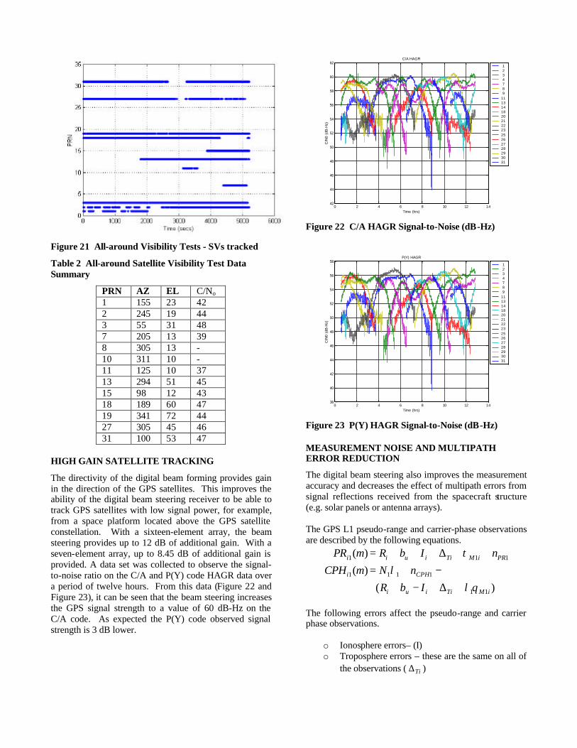
Figure 21 All-around Visibility Tests - SVs tracked
Table 2 All-around Satellite Visibility Test Data Summary
PRN AZ EL C/No 1 155 23 42 2 245 19 44 3 55 31 48 7 205 13 39 8 305 13 - 10 311 10 - 11 125 10 37 13 294 51 45 15 98 12 43 18 189 60 47 19 341 72 44 27 305 45 46 31 100 53 47
HIGH GAIN SATELLITE TRACKING
The directivity of the digital beam forming provides gain in the direction of the GPS satellites. This improves the ability of the digital beam steering receiver to be able to track GPS satellites with low signal power, for example, from a space platform located above the GPS satellite constellation. With a sixteen-element array, the beam steering provides up to 12 dB of additional gain. With a seven-element array, up to 8.45 dB of additional gain is provided. A data set was collected to observe the signal-to-noise ratio on the C/A and P(Y) code HAGR data over a period of twelve hours. From this data (Figure 22 and Figure 23), it can be seen that the beam steering increases the GPS signal strength to a value of 60 dB-Hz on the C/A code. As expected the P(Y) code observed signal strength is 3 dB lower.
0 2 4 6 8 10 12 1442
44
46
48
50
52
54
56
58
60
62
C/N
0 (d
B-H
z)
Time (hrs)
C/A HAGR
1 2 3 4 7 8 9111314182021222325262728293031
Figure 22 C/A HAGR Signal-to-Noise (dB-Hz)
0 2 4 6 8 10 12 1438
40
42
44
46
48
50
52
54
56
58
C/N
0 (d
B-H
z)
Time (hrs)
P(Y) HAGR
1 2 3 4 7 8 9111314182021222325262728293031
Figure 23 P(Y) HAGR Signal-to-Noise (dB-Hz)
MEASUREMENT NOISE AND MULTIPATH ERROR REDUCTION
The digital beam steering also improves the measurement accuracy and decreases the effect of multipath errors from signal reflections received from the spacecraft structure (e.g. solar panels or antenna arrays). The GPS L1 pseudo-range and carrier-phase observations are described by the following equations.
)(
)(
)(
11
1111
111
iMTiiui
CPHi
PRiMTiiuii
IbR
nNmCPH
nIbRmPR
θλλ
τ
+∆+−+−+=
++∆+++=
The following errors affect the pseudo-range and carrier phase observations.
o Ionosphere errors– (I) o Troposphere errors – these are the same on all of
the observations ( Ti∆ )
o Receiver Measurement Noise – these are different on each of the observations ( 1PRn , 1CPHn )
o Multipath Noise – these are different on each of the observations ( iM1τ , iM11θλ )
o Satellite and Station Position error - these affect the ability to correct for the Range to the satellite (Ri)
o Receiver clock offset (bu) From these equations, the L1 pseudo-range + carrier phase sum cancels out the common errors and the range to the satellite, leaving the pseudo-range and multipath errors as well as the change in the ionospheric offset.
11
11111
111111111
2
)(2
2)(
PRiMi
iMCPHPRiMi
iMCPHPRiMiii
nIC
nnIC
nNnImCPHPR
+++≈
−++++=
−++++=+
τ
θλτ
θλλτ
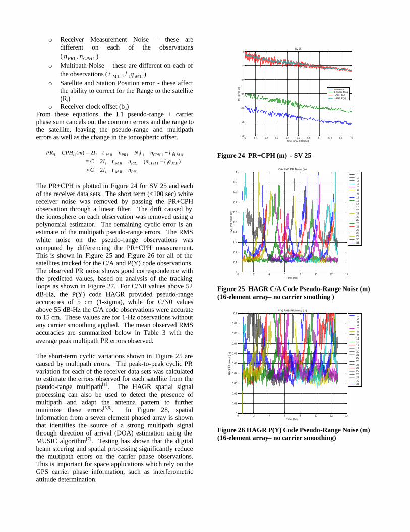
The PR+CPH is plotted in Figure 24 for SV 25 and each of the receiver data sets. The short term (<100 sec) white receiver noise was removed by passing the PR+CPH observation through a linear filter. The drift caused by the ionosphere on each observation was removed using a polynomial estimator. The remaining cyclic error is an estimate of the multipath pseudo-range errors. The RMS white noise on the pseudo-range observations was computed by differencing the PR+CPH measurement. This is shown in Figure 25 and Figure 26 for all of the satellites tracked for the C/A and P(Y) code observations. The observed PR noise shows good correspondence with the predicted values, based on analysis of the tracking loops as shown in Figure 27. For C/N0 values above 52 dB-Hz, the P(Y) code HAGR provided pseudo-range accuracies of 5 cm (1-sigma), while for C/N0 values above 55 dB-Hz the C/A code observations were accurate to 15 cm. These values are for 1-Hz observations without any carrier smoothing applied. The mean observed RMS accuracies are summarized below in Table 3 with the average peak multipath PR errors observed. The short-term cyclic variations shown in Figure 25 are caused by multipath errors. The peak-to-peak cyclic PR variation for each of the receiver data sets was calculated to estimate the errors observed for each satellite from the pseudo-range multipath[1]. The HAGR spatial signal processing can also be used to detect the presence of multipath and adapt the antenna pattern to further minimize these errors[5,6]. In Figure 28, spatial information from a seven-element phased array is shown that identifies the source of a strong multipath signal through direction of arrival (DOA) estimation using the MUSIC algorithm[7]. Testing has shown that the digital beam steering and spatial processing significantly reduce the multipath errors on the carrier phase observations. This is important for space applications which rely on the GPS carrier phase information, such as interferometric attitude determination.
5 5.1 5.2 5.3 5.4 5.5 5.6 5.7 5.8 5.9 6-30
-25
-20
-15
-10
-5
0
PR
+CP
H (
m)
SV 25
Time since 0:00 (hrs)
1-Antenna1-Choke RingHAGR C/AHAGR P(Y)
Figure 24 PR+CPH (m) - SV 25
0 2 4 6 8 10 12 140
0.1
0.2
0.3
0.4
0.5
0.6
0.7
0.8
0.9
1
RM
S P
R N
oise
(m
)
Time (hrs)
C/A RMS PR Noise (m)
1 2 3 4 7 8 9111314182021222325262728293031
Figure 25 HAGR C/A Code Pseudo-Range Noise (m) (16-element array– no carrier smothing )
0 2 4 6 8 10 12 140
0.01
0.02
0.03
0.04
0.05
0.06
0.07
0.08
0.09
0.1
RM
S P
R N
oise
(m
)
Time (hrs)
P(Y) RMS PR Noise (m)
1 2 3 4 7 8 9111314182021222325262728293031
Figure 26 HAGR P(Y) Code Pseudo-Range Noise (m) (16-element array– no carrier smoothing)

40 42 44 46 48 50 52 54 56 58 6010
-2
10-1
100
C/N0 (dB)
RM
S P
R E
rror
(m
)
HAGR C/AHAGR P(Y)
Figure 27 C/A and P(Y) HAGR RMS PR error versus C/N0
Table 3 Mean PR Noise and M-path Peak Errors (m) (16-element array)
SVID C/A HAGR
RMS PR
C/A Mean Mpath PR
P(Y) HAGR
RMS PR
P(Y) Mean
Mpath PR 1 0.239 0.259 0.054 0.202 3 0.284 0.494 0.056 0.337 8 0.200 0.278 0.045 0.202 11 0.278 0.535 0.059 0.287 13 0.252 0.321 0.059 0.260 14 0.214 0.359 0.049 0.350 20 0.222 0.267 0.050 0.164 21 0.252 0.261 0.058 0.133 22 0.248 0.318 0.047 0.217 25 0.202 0.362 0.044 0.265 27 0.183 0.270 0.044 0.178 28 0.236 0.366 0.055 0.272 29 0.225 0.312 0.050 0.217 30 0.477 0.791 0.089 0.624 31 0.325 0.266 0.055 0.135
Figure 28 MUSIC direction of arrival estimation
CONCLUSION
The test data presented in this paper has shown that the digital beam steering architecture has advantages for the SSGR application: specifically it increases the received
GPS signal/noise ratio, which improves the tracking performance for low power satellite signals; improves the measurement accuracy for precision applications such as rendezvous, docking, or formation flying and minimizes carrier phase multipath errors, which can result in improved interferometric attitude determination. The SSGR described in this paper is being built under contract to NASA Goddard Space Flight Center (GSFC). This modular, flexible architecture is designed to be ported to a variety of space-qualified signal processing boards and host computers to provide an embedded GPS capability. The design also allows the receiver to be reconfigured in flight to optimize the GPS tracking performance depending on the needs of each phase of the mission. To aid in testing of this space qualified receiver, the NAVSYS GPS Toolbox and AGHS products have been augmented to include tools to allow simulation of GPS data in a space environment. In addition, the IMU simulation capability of the InterNav product has also been incorporated into the AGHS design.
ACKNOWLEDGEMENTS
This work is being sponsored under an SBIR contract to NASA GSFC. The authors would like to express their appreciation for the support of Dr. Michael Moreau, the technical point at GSFC.
REFERENCES
[1]Gold, K, A. Brown, “A Software GPS Receiver Application for Embedding in Software Definable Radios” Proceedings of ION GPS/GNSS 2003, Portland, OR, Sept. 2003 [2] May, M., A. Brown, “Digital Storage Receivers for Enhanced Signal Processing, ”,Proceedings of the ION GPS ‘99, Nashville, TN, Sept. 1999 [3] http://www.stk.com/ [4]Nylund, M, A. Brown, “Kinematic GPS-Inertial Navigation on a Tactical Fighter”, Proceedings of ION GPS/GNSS 2003, Portland, OR, Sept. 2003 [5] A. Brown, “Performance and Jamming Test Results of a Digital Beamforming GPS Receiver,” Joint Navigation Conference, Orlando, FL, May, 2002.
[6] D. Sullivan, R. Silva, and A. Brown, “High Accuracy Differential and Kinematic GPS Positioning using a Digital Beam Steering Receiver,” Proceedings of 2002 Core Technologies for Space Systems Conference, Colorado Springs, CO, November 2002.
[7] A. Brown and K. Stolk; “Rapid Ambiguity Resolution using Multipath Spatial Processing for High Accuracy Carrier Phase, Proceedings of ION GPS 2002, Portland, OR, September 2002.