graduation project final report - semantic …...graduation project final report ambient...
TRANSCRIPT

GRADUATION PROJECT
FINAL REPORT
Ambient Intelligence in Home Environments
Project Members
Elif Bozkurt 5252
Mehmet Onur Sarkan 5241
Project Supervisor
Aytül Erçil
June 23, 2004
Faculty of Engineering and Natural Sciences, Telecommunications Engineering
Sabanci University

Abstract
The system described in this report is a Computer Vision Tracking System that tracks a
person in a room with a pan-tilt camera in real-time and warns in case of an unexpected
situation such as detection of fire or it can be falling of a person. The warning message can be
sent via e-mail or it can be an alarm message. For human motion tracking Kanade-Lucas-
Tomasi Optical Flow technique and Differential Motion Analysis and for fire detection Flame
Recognition method in Video are implemented with Intel’s Open Source Computer Vision
(OpenCV) Library. The pan-tilt servo motors are controled with ActiveX from the serial port.
The software also consists of a graphical user interface (GUI), where tracking or fire detection
can be actuated in real time.

Table Of Contents
1. Introduction 2. System Description 3. Human Tracking
A. Differential Motion Analysis B. Optical Flow
a. Computation of Optical Flow b. Pyramidal Implementation of the Lucas-Kanade Algorithm for Feature
Tracking 4. Fire Detection
A. Detection of Fire Colored Pixels: B. Finding Temporal Variation: C. Finding Fire Pixels D. Improvement by Erosion & Fire Alarm
5. Unexpected Situations 6. Feedbacks A. Alarm Sounds
B. Automatic E-mail 7. Hardware Information A. Computer Controlled Pantilt Unit 46-70 & Pantilt Control
B. Sony DFW-VL500 CCD VIDEO CAMERA C. TOSHIBA Satellite 1400-103 Notebook D. Tripod E. Digitus USB-RS232 Adapter
8. Software Information 9. Demonstration Requirements
A. Pantilt Setup B. Camera Setup: C. Remote Control Setup:
10. Graphical User Interface Manual 11. Conclusion 12. References

1. Introduction
Ambient intelligence is a digital environment that is responsive and adaptive to human
presence. Within a home environment ambient intelligence can improve the quality of life by
creating a functional, inter-connected, personalized systems and services. Ambient
intelligence technologies are expected to combine concepts of ubiquitous computing and
intelligent systems putting humans in the centre of technological developments.
Today’s many intelligent systems utilize forms of inputs from video cameras. The basic usage
of such computer vision based systems is motion tracking, for our project namely human
motion tracking and fire detection with a pan-tilt camera. Additionally, our system is capable
of sending a warning message in case of an unexpected situation (fire detection or it can be
falling of a person)
Some examples of applications with reliable human motion detection and tracking are:
• Automated surveillance for security-conscious venues such as airports, casinos, museums,
and government installations: Intelligent software could monitor security cameras and detect
suspicious behavior. Automated surveillance increases the productivity of the human operator
and coverage of the surveillance.
• Human interaction with mobile robotics: Autonomous mobile robots in the workplace or
home could interact with the humans around them if they could reliably detect their presence.
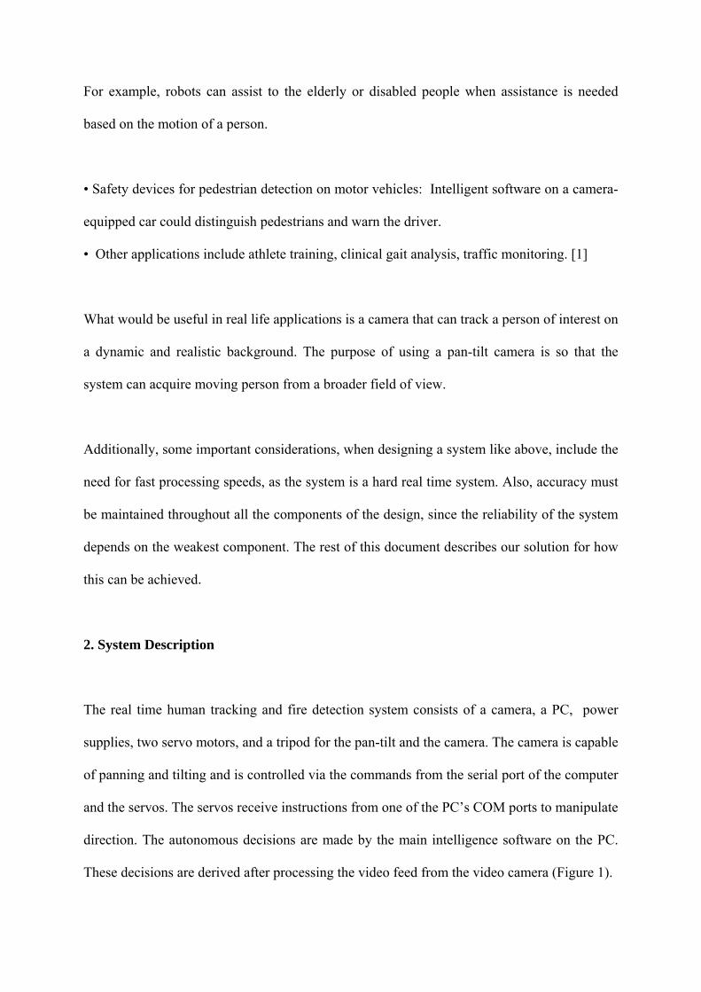
For example, robots can assist to the elderly or disabled people when assistance is needed
based on the motion of a person.
• Safety devices for pedestrian detection on motor vehicles: Intelligent software on a camera-
equipped car could distinguish pedestrians and warn the driver.
• Other applications include athlete training, clinical gait analysis, traffic monitoring. [1]
What would be useful in real life applications is a camera that can track a person of interest on
a dynamic and realistic background. The purpose of using a pan-tilt camera is so that the
system can acquire moving person from a broader field of view.
Additionally, some important considerations, when designing a system like above, include the
need for fast processing speeds, as the system is a hard real time system. Also, accuracy must
be maintained throughout all the components of the design, since the reliability of the system
depends on the weakest component. The rest of this document describes our solution for how
this can be achieved.
2. System Description
The real time human tracking and fire detection system consists of a camera, a PC, power
supplies, two servo motors, and a tripod for the pan-tilt and the camera. The camera is capable
of panning and tilting and is controlled via the commands from the serial port of the computer
and the servos. The servos receive instructions from one of the PC’s COM ports to manipulate
direction. The autonomous decisions are made by the main intelligence software on the PC.
These decisions are derived after processing the video feed from the video camera (Figure 1).

ta
Figure
video c
playing
3. Hu
First o
non-st
Differ
conse
Toma
but fo
Motio
A gen
• • • •
camer
1. System components, the above system m
amera, if there exists an unexpected situati
an alarm sound.
man Motion Tracking
f all, to detect motion we can take
ationary when compared to the bac
ential Motion analysis which dete
cutive images. There also exists m
si optical flow method. We tried bo
r its simpler implementation and
n Analysis method.
eric configuration of our computer v
Images are acquired at a fixed samA foreground extraction componeTracking component Interpretation component
Processing software
Pan-tilt control software Servo motorsainly tracks a person and detects fire fr
on the feedback mechanism sends a warn
the advantage of knowledge that
kground. The most basic of dete
cts motion by considering the d
ore complex methods such as t
th methods, they have advantages
less complexity we chose to u
ision system for tracking include
pling rate (30 frames/sec) nt
Feedback Uni
om the inputs of the
ing via e-mail or by
moving objects are
cting motion is the
ifference values of
he Lucas-Kanade-
and disadvantages
se the Differential
s five parts :

• Feedback component
A - Differential Motion Analysis Method
Differential motion analysis is fairly a straight forward method. We separate regions of an
image in a way that resembles how a human would naturally perceive them. Since we are
interested in motion, our approach is to segment those regions of the image that are moving
relative to the background. Once the moving objects are subtracted from the background, we
can track them. [2]
The above method, of course, works best if the camera is stationary so that the background
does not change at all, but it is also possible to use it when the camera is not stationary
provided that the time interval between the two image frames is small enough, and the
movement of the background significantly smaller than movement of the object. We used 30
images per second as input from the camera, so it is fast enough to use the differential motion
analysis method. After subtracting the images, a threshold value is determined in the resulting
differential image to remove small changes than can be the result of changes in lighting
conditions or noise. Below are some resulting figures for this method (Figures 2,3 and 4) :

Figure 2. First image
Figure 3. Second image

Figure 4. The difference image (Second image – First image)
Moreover, after we get the differences of consecutive images by using the cvAbsDiff function
of OpenCV (Figure 4), we threshold the resulting image (with the function cvThreshold)
according to the below algorithm [6], we set a threshold value that we only have the motion
pixels in the image. (Figure 5). Then, we eliminate the noisy pixels (may occur due to lighting
effects) with the erosion and dilation morphological operations. cvErode and cvDilate
functions of OpenCV are used for this purpose. [8] We try morphological operations several
times until we get rid of the noise .
⎩⎨⎧
≤>
=thresholdyxIthresholdyxI
yxIdifference
differencethreshed ),(,0
),(,1),(

Figure 5. Thresholded image
Furthermore, since we get the motion pixels it would be practical to track these pixels with a
rectangle around for a better analysis of motion. It is easier to find the location of the moving
object with a rectangle. To create a rectangle, first we need to find the external contour of the
motion pixels. We used OpenCV’s cvFindContours, cvStartFindContours and
cvFindNextContour functions and get the below image (Figure 6) [8]. Afterwards, rectangle is
created with the cvContourBoundingRect and cvRectangle functions and next, the center
point of the rectangle can be easily found. (Figure 7) [8]

Figure 6. Contour of the moving target
Figure 7. Bounding box for the tracked person and center of the box

In addition, following these operations, for tracking with the pan-tilt, it is sensible to track the
center point of the bounding box. Whenever, the tracked person is about to exit from the
camera’s sight of view, the pan-tilt manipulates the pan (horizontal movement) and tilt
(vertical movement) angles. A region of interest is (Figure 8) considered and if the center
point is outside of this region, the step by step turning of the camera (approximately a step is
15o) in the same direction with the moving person is realized (Figure 9). The region of interest
is a rectangle of size 400x400 pixels (Figure 8) where the original image is of size 640x480
pixels.
Figure 8. Region of interest for tracking the center point of the Bounding Box

Figure 9. Pan-tilt movement and the room
B - Optical Flow Method
Another possible way to detect moving objects is by investigating the optical flow which is an
approximation of two dimensional flow field from the image intensities, is computed by
extracting a dense velocity field from an image sequence. The optical flow field in the image
is calculated on basis of the two assumptions that the intensity of any object point is constant
over time and that nearby points in the image plane move in a similar way. [1]
Additionally, the easiest method of finding image displacements with optical flow is the
feature-based optical flow approach that finds features (for example, image edges, corners,
and other structures well localized in two dimensions) and tracks these as they move from
frame to frame.
Furthermore, feature based optical flow method involves two stages. Firstly, the features are
found in two or more consecutive images. The act of feature extraction, if done well, will both
reduce the amount of information to be processed (and so reduce the workload), and also go

some way towards obtaining a higher level of understanding of the scene, by its very nature of
eliminating the unimportant parts. Secondly, these features are matched between the frames.
In the simplest and commonest case, two frames are used and two sets of features are matched
to give a single set of motion vectors.[5]
Additionally, finding optic flow using edges has the advantage (over using two dimensional
features) that edge detection theory is well advanced. It has the advantage over approaches
which attempt to find flow everywhere in the image. The features are found according to the
below algorithm:
Feature selection algorithm :
1. Compute the spatial gradient matrix and its minimum eigenvalue at every pixel in the image I.
2. Call the maximum value of eigen values over the whole image. 3. Retain the image pixels that have a eigen value larger than a percentage of maximum
eigen values. This percentage can be 10% or 5%. 4. From those pixels, retain the local max. pixels (a pixel is kept if its eigen value is
larger than that of any other pixel in its 3 x3 neighborhood). 5. Keep the subset of those pixels so that the minimum distance between any pair of
pixels is larger than a given threshold distance (e.g. 10 or 5 pixels).[4]
1. Computation of Optical Flow :
The idea of optical flow is to calculate some function, velocity vector v = (u,v), for each pixel
in an image. The function v (u,v) describes how quickly each particular pixel is moving across
the image stream along with the direction in which the pixel is moving.
Consider an image stream described in terms of intensity as I(x,y,t). The intensity’s position
change over time is:

I (x+dx, y+dy, t+dt) = I (x,y,t) + dxxI
∂∂ + dy
yI
∂∂ + dt
tI
∂∂ … (1)
If there is no change in position over time:
I (x+dx, y+dy, t+dt) = I (x,y,t) (2)
To simplify things, define:
dtdxu = and
dtdyv = (3)
In this respect, u and v are the speeds the intensity is moving. Now, as dt approaches zero:
vyIu
xI
tI
∂∂
+∂∂
=∂∂
− (4)
Equation 4 above relates the change of a pixel’s intensity with time to the spatial rates of
change of intensity within an image. Now, tI
∂∂ at a given pixel is just how fast the intensity
is changing with time, while xI
∂∂ and y
I∂
∂ are the spatial rates of change of intensity.
Practically, Optical Flow is mainly used for the detection of a falling person. Since we get the
feature points in the consecutive images and we can track them, it is an easy task to find the
direction and the velocity of changes in the feature points of the moving person. Whenever,
there is a fast downward movement, the distance between the feature points increases and if
we combine the sequential points with a line, we observe that this line is almost perpendicular
to the ground (Figure 10). [3]
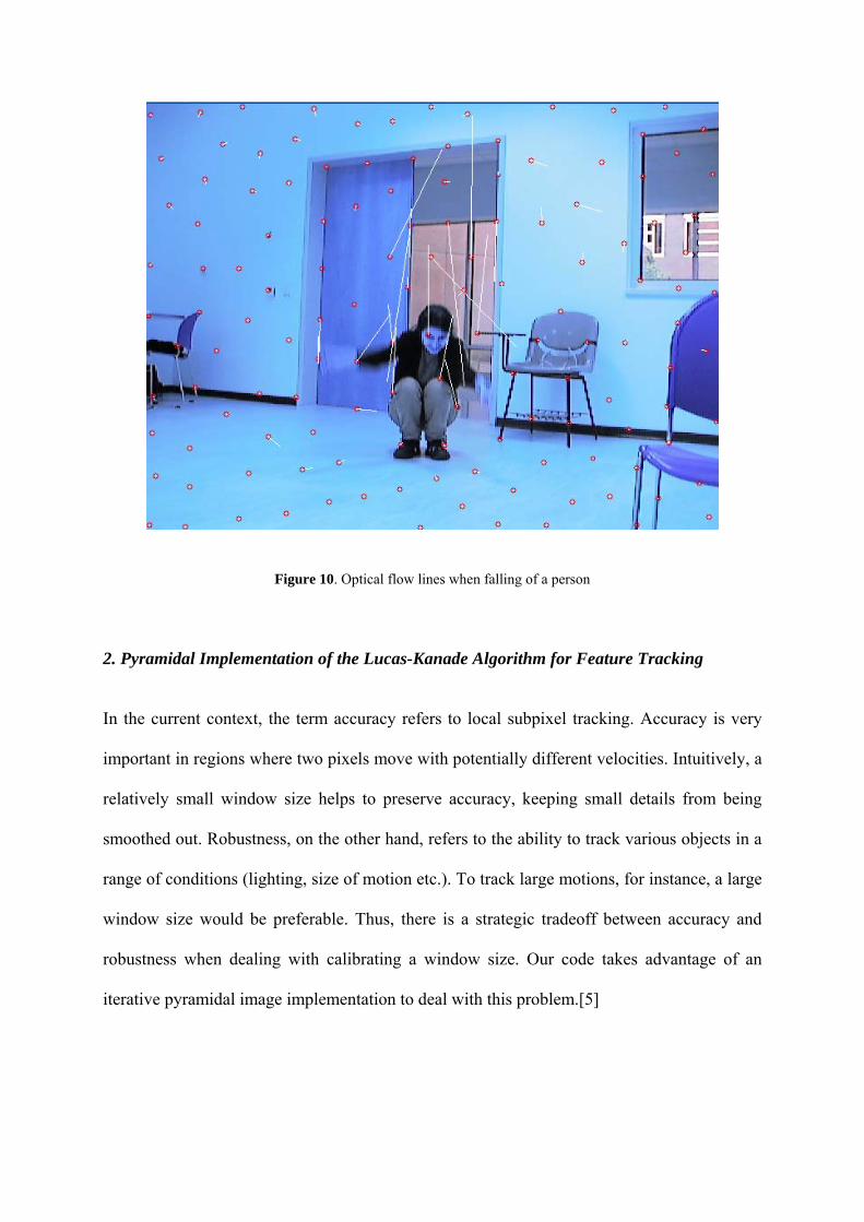
Figure 10. Optical flow lines when falling of a person
2. Pyramidal Implementation of the Lucas-Kanade Algorithm for Feature Tracking
In the current context, the term accuracy refers to local subpixel tracking. Accuracy is very
important in regions where two pixels move with potentially different velocities. Intuitively, a
relatively small window size helps to preserve accuracy, keeping small details from being
smoothed out. Robustness, on the other hand, refers to the ability to track various objects in a
range of conditions (lighting, size of motion etc.). To track large motions, for instance, a large
window size would be preferable. Thus, there is a strategic tradeoff between accuracy and
robustness when dealing with calibrating a window size. Our code takes advantage of an
iterative pyramidal image implementation to deal with this problem.[5]

Let us define the pyramidal representation of image I of size nx x ny. Let 0I = I be the zeroth
level image. This image is essentially the highest resolution image ( the raw image).
The pyramid representation is built in a recursive fashion : Compute 1I from 0I , then compute 2I from 1I and so on. L = 1, 2, 3,… is the pyramid level and 1−LI is the image at level L – 1.
LI is computed as :
[ ]
[ ])12,12()12,12()12,12()12,12(161
)12,2()12,2()2,12()2,12(81)2,2(
41),(
1111
11111
−−+++++−++++
−+++−+++=
−−−−
−−−−−
yxIyxIyxIyxI
yxIyxIyxIyxIyxIyxI
LLLL
LLLLLL
and is only defined for values of x, y that :
120 1 −≤≤ −Lxnx and 120 1 −≤≤ −L
yny For example, for an image I of size 640 x 480 ,
The images are of respective sizes 320 x 160 , 160 x 80 , 80 x 60 and 40 x
30.
4321 ,, IandIII
The central motivation behind the pyramidal representation is to be able to handle large pixel
motions. Therefore, the pyramid height Lm should be picked appropriately according to the
maximum expected optical flow. For an image size of 640x480 as in our project, to choose a
pyramid level of four gives good results.
For a feature u=(ux,uy) in image I, uL=(ux
L,uyL) is the corresponding feature in the image IL.

LL uu
2=
The overall pyramidal tracking proceeds as follows : - First, the optical flow is computed at the deepest pyramid level Lm .
- Then, the result of that computation is propagated to the upper level Lm
– 1 in a form of initial guess for the pixel displacement in this level.
- The result is propagated to the level Lm
– 2 and so on up to level 0 (the original image).
To propagate from one level to next one, we define the image matching error function EL.
2
)),(),(()( ∑ ∑+
−=
+
−=
++++−=xx
xx
yy
yy
wu
wux
wu
wuy
Ly
Ly
Lx
Lx
LLLL gdygdxJyxIdE
where I is the first image and J is the second image.
Assuming the levels in question are levels L and L+1, and also that gL is the initial guess of
the optical flow in level L, derived from computations from level Lm to L+1, the optical flow
at level L is then found by finding the displacement vector dL that minimizes the image
matching error function defined above. The window of integration for these calculations is
constant for all L, explicitly, (2wx+1)x(2wy+1).
Essentially, the initial guess of the optical flow, gL , is used to pre-translate the image portion
of interest in the second image, therefore resulting in a quick calculation of dL using a Lucas-
Kanade step. The next initial guess, gL-1 =2(gL + dL ) is then passed to the next level, L-1. At
that point, dL-1 is calculated via the same procedure, and so on, until the level L=0 is reached.
To start the procedure, the initial guess of the optical flow for Lm is gLm =(0,0). The final
solution for the optical flow and location of point on next image are respectively :
∑=
=+=mL
L
LL ddgd0
00 2 and v = u + d
Since we use the pyramidal representation; each optical vector, dL , is kept relatively small
while the total pixel displacement vector, d, is computed, allowing large pixel motions with
practically sized windows of integration. [5]
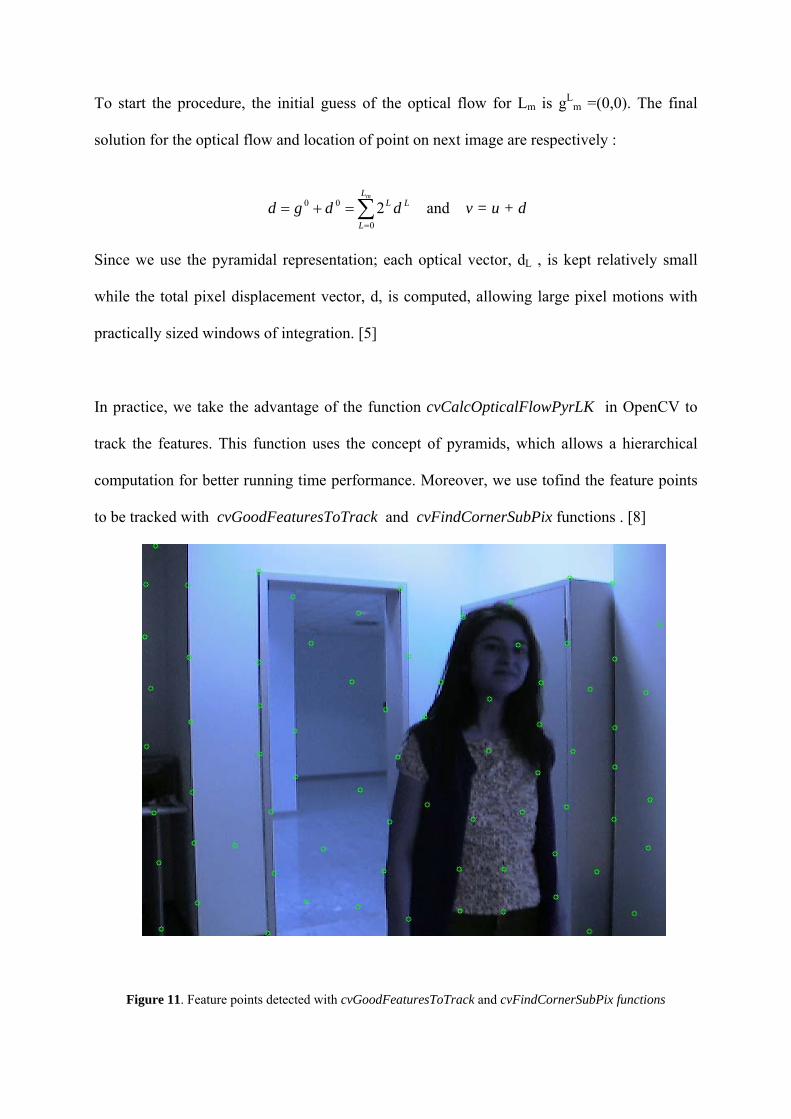
In practice, we take the advantage of the function cvCalcOpticalFlowPyrLK in OpenCV to
track the features. This function uses the concept of pyramids, which allows a hierarchical
computation for better running time performance. Moreover, we use tofind the feature points
to be tracked with cvGoodFeaturesToTrack and cvFindCornerSubPix functions . [8]
Figure 11. Feature points detected with cvGoodFeaturesToTrack and cvFindCornerSubPix functions

Figure 12. Optical Flow results from figures 2 and 3 on the original image
Figure 13. Optical flow result from figures 2 and 3 on a blank image, white lines show the direction of motion

4. Fire Detection
Every year, thousands of people die in the home fires. There are a lot of reasons for these fires
like short circuits in electricity, children who play with match sticks, etc. Fire can easily grow
up in room conditions because there are a lot of flammable objects in homes like carpets,
curtains, wooden chairs, tables, etc. To reduce damage, we have to immediately try to
extinguish fire as soon as possible. In our project, to try to protect target person, we developed
fire detection system based on video processing. When fire is detected, alarm sound begin to
play with high volume. By this alarm sound, if there is a person in the next rooms, he or she
can protect target person.
We designed our fire detection system based on Flame Recognition in Video method [7]. In
this method, color and motion information are computed from video sequences to detect fire.
According to RGB color information of pixels, fire colored pixel are detected. Fire colored
pixels are possible fire pixels. To ensure about fire, temporal variations of fire colored pixels
are calculated. If temporal variation is above some level, fire is detected.
Our fire detection system contains three main parts: 1- Finding fire colored pixels (possible fire pixels) 2- Controlling temporal variations of fire colored pixels 3- According to temporal variations, detection of fire
A -Detection of Fire Colored Pixels:
To find possible fire pixels, firstly we find fire colored pixels according to RGB values of video frames. We used following RGB values to detect fire [9]:
R>220 G>200 125<B<185

R>220 125<G<150 75<B<100
R>220 175<G<225 75<B<125
Most of the fire colored pixels is in these three ranges. So, if one pixel’s RGB values are in
these ranges, it is fire colored pixel. Nature of fire is translucent. So, this transparency makes
difficult fire to detect. Because of this reason, we average the fire color estimate over small
windows of time. Simply, we find fire colored pixels for each frames. We process last n
frames to decide real fire colored pixels. To calculate fire color probability (Colorprob), we
calculate average colorlookup value for last n frames. Colorlookup value is 1 if pixel values
are in fire ranges, zero otherwise. If colorprob is higher than some threshold value k1, this
pixel is real fire colored pixel. Following equations summarize these calculations:
In our project, we choose n is equal five, and k1 is equal to 0.2. This means that if one pixel is
minimum two times in fire color region for last five frames, this pixel is real fire colored
pixel. Following two examples are belonging to detection of fire colored pixels. First images
are real RGB images, and second images are output of detection of fire colored pixels. Blue
pixels are detected pixels:

Figure 14. Detection of Fire colored Pixels, Example 1
Figure 15. Detection of Fire colored Pixels, Example 2
B - Finding Temporal Variation:
Color is not always enough to detect fire correctly. Because in home environment, there can
be a lot of things, which have similar colors with fire kinds. To distinguish fire, we use
temporal variation of fire colored pixels. Video camera can takes 30 frames per second. It is
enough to observe characteristic motion of flames.
We use temporal variation in conjunction with fire color to detect fire pixels. Temporal
variation for each pixel, denoted by Diffs, is computed by finding the average of pixel-by
pixel absolute intensity difference between consecutive frames. However, this difference may
be misleading, because the pixel intensity may also vary due to global motion in addition to
fire flicker. Therefore, we also compute the pixel-by-pixel intensity difference for non-fire

color pixels, denoted by nonfireDiffs, and subtract that quantity from the Diffs to remove the
effect of global motion.
Temporal variation for each pixel is calculated by following equation:
By this equation, we calculate total intensity change in last five frames. In this equation, n is equal to 5. Our output is total intensity change results in matrix.
Pixel by pixel, average total intensity difference for non-fire color pixels is calculated by following equation:
By this equation, we approximately calculate average intensity changing due to the global motion.
We subtract average intensity changing due to the global motion from total intensity changing
of last five frames, so we calculate effective total intensity difference of last five frames.
Following equation summarize this procedure:

C - Finding Fire Pixels:
Finally, we can detect fire. When color is fire color, and temporal variation is higher than
some k2 threshold value, this means that there is a fire. We choose k2 is equal to 10. Next
equation explains this detection. .
In the following two examples, you can see fire detection results. Blue areas have high temporal intensity variation.
Figure 16. Detection of Fire Pixels, Example 1
Figure 17. Detection of Fire Pixels, Example 2
D - Improvement by Erosion & Fire Alarm: Sometimes, there can be local noisy high intensity changing with fire colors when there is no
fire. To improve our system, we apply erosion on ∆I(x,y) matrix. So, we can reduce noisy
effects of mobile fire colored objects. After this erosion operation, we count number of fire
pixels. If this number is higher then some threshold value, there is a fire with very high
probability. This means that fire is detected. When fire is detected, alarm sound automatically
begins to play, and automatic e-mail is sent.
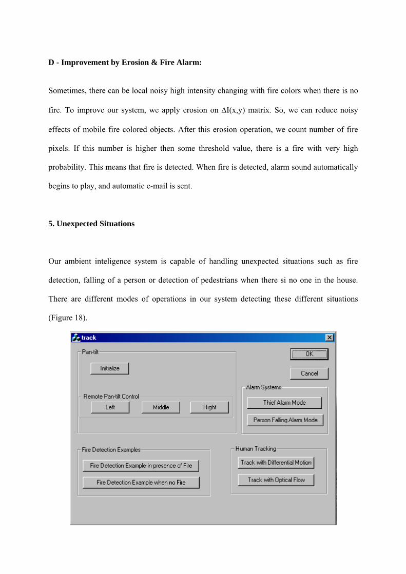
5. Unexpected Situations
Our ambient inteligence system is capable of handling unexpected situations such as fire
detection, falling of a person or detection of pedestrians when there si no one in the house.
There are different modes of operations in our system detecting these different situations
(Figure 18).

Figure 18. MFC user interface for the project, modes of operations
Furthermore, with the remote conrolling mechanism, it is possible to view inside of the room
even if, you are not home. With this system it is possible to check whether there is an
unexpected situation manually from the buttons “Left”, “Middle” and “Right”.
Additionally, in case of any unexpected situation the feedback mechanism is activated and the
warning is sent.
6. Feedbacks Aim of this project is to help us about unusual events by warning. This means that one of the
most important parts of this project is feedback stage. There are two main feedback methods
in this system: These are alarm sounds with high volume and e-mail. For example, when you
are at home, if your children or handicapped relatives fall,or fire begins, alarm sound begin to
play with high volume, so you can easily interfere to unusual events. Also, you can control
unusual events by checking your emails.
A - Alarm Sounds: We recorded alarm all possible alarm sounds. When unusual events are detected in our C++ codes, we run winanp.exe with suitable alarm sound file by help of process.h library. B - Automatic E-mail: We wrote all possible e-mail templates. When unusual events are detected in our C++ codes, our computer is connected to email server, our computer host name is checked and after verification, most suitable email template is sent to the target email address.
7. Hardware Information
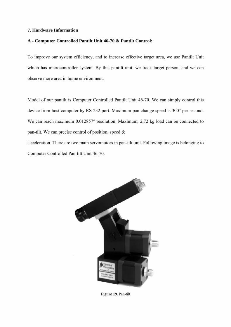
A - Computer Controlled Pantilt Unit 46-70 & Pantilt Control: To improve our system efficiency, and to increase effective target area, we use Pantilt Unit
which has microcontroller system. By this pantilt unit, we track target person, and we can
observe more area in home environment.
Model of our pantilt is Computer Controlled Pantilt Unit 46-70. We can simply control this
device from host computer by RS-232 port. Maximum pan change speed is 300° per second.
We can reach maximum 0.012857° resolution. Maximum, 2,72 kg load can be connected to
pan-tilt. We can precise control of position, speed &
acceleration. There are two main servomotors in pan-tilt unit. Following image is belonging to
Computer Controlled Pan-tilt Unit 46-70.
Figure 19. Pan-tilt

Computer controlled Pan-Tilt Unit has own micro controller. Our laptop is connected to pan-
tilt unit by RS 232 port. In our laptops, there is no RS 232 port, because of this reason; we use
RS 232 to USB converter. This pan-tilt unit has own control syntax. Pan position, Tilt
position, Pan speed, Tilt speed etc, can be easily controlled by simple basic syntax of pan-tilt
unit. Following figure explain schematic of pan-tilt unit.
Figure 20. Connection of the Pan-tilt
Pan-tilt controller is connected to host computer by RS 232 port. Host computer send
commands for pan-tilt unit to micro controller. Micro controller compile these commands,
and it control pan and tilt servomotors. To send commands from host computer, we use
Microsoft Communication ActiveX control. We create command in c++ codes, we convert
them into strings, and we send these strings by COM port with ActiveX Communication
control. According to our needs, we can easily control the pantilt unit in our project codes.

B - Sony DFW-VL500 CCD VIDEO CAMERA:
Figure 21. Sony DFW-VL 500 camera
This graduation project is an image-processing project. So, video camera becomes very
important device of this project. We chose Sony DFW-VL500 CCD Camera. The DFW-
V500/VL500 is a color digital video camera utilizing a 1/3-type PS IT CCD. The DFW-V500
is the C-mounted type while the DFW-VL500 is a 12� zoom lens mounted type. The
IEEE1394-1995 digital interface realizes a transfer speed of 400M bps and outputs of VGA
(640 x480)/YUV (4 : 2 : 2)/30 fps. In addition, the DFW-V500/VL500 also adopts a primary
color filter CCD to realize good color reproductively. Furthermore, the digital transmitting
brings high quality of original image without “Analog-to-Digital conversion”. The square
pixels eliminate the need for aspect ratio conversion in the image processor. This camera is
very suitable for our system. We didn’t have any problem with video camera.

C - TOSHIBA Satellite 1400-103 Notebook:
Figure 22. Toshiba Satellite Notebook
The main part of our system is image-processing stage. We are using Toshiba Satellite 1400-
103 Notebook. This computer has Intel Celeron 1.33 GHz Processor, 256 MB RAM, and 20
GB Hard disk. This computer can easily run our source codes.
D - Tripod:
Figure 23. the tripod
To carry pan tilt unit and camera, we used Valon 3150 Tripod. We can control height and
direction of this tripod.
E - Digitus USB-RS232 Adapter:
Our laptop doesn’t have any RS232 port. To connect computer and computer controlled pan
tilt unit, we used Digitus USB-RS232 adapter. This adapter can establish RS232 connection
on the one of the USB port of computer.

8. Software Information
OpenCV:
In our project, to process video frames, we used OpenCV 3.1 library. OpenCV means Intel®
Open Source Computer Vision Library. It is a collection of C functions and few C++ classes
that implement some popular algorithms of Image Processing and Computer Vision.OpenCV
is cross-platform middle-to-high level API that consists of a few hundreds (>300) C functions.
It does not rely on external numerical libraries, though it can make use of some of them at
runtime, if they are available.
OpenCV is free for both non-commercial and commercial use. OpenCV provides transparent
for user interface to Intel® Integrated Performance Primitives. That is, it loads automatically
IPP libraries optimized for specific processor at runtime, if they are available.
There are interfaces to OpenCV for some other languages/environments:
• EiC - ANSI C interpreter written by Ed Breen. AFAIK, it is now abandoned. Hawk and CvEnv are the interactive environments (written in MFC and TCL, respectively) that embed EiC interpreter.
• Ch - ANSI C/C++ interpreter with some scripting capabilities, created and supported by Soft Integration® company Wrappers for Ch are located at opencv/interfaces/ch.
• MATLAB® - great environment for numerical and symbolic computing by Mathworks. MATLAB® interface for some of OpenCV functions can be found at opencv/interfaces/matlab/toolbox
9. Demonstration Requirements
A - Pantilt Setup: *Install USB to RS232 Adapter Driver *Connect computer and Pantilt Micro Controller Unit from COM5 port of computer by USB to RS232 Adapter Cable *Connect the Pantilt power cables

*Open power of Pantilt from Micro Controller Box B - Camera Setup: *Install the Camera 1394 software *Connect Camera and computer by firewire cable C - Remote Control Setup: *Install Remote Administrator 2.1 *Set properties of remote connections(connection passwords, target computer IP, etc.) 10. Graphical User Interface Manual
Figure 24. User Interface
Initialize Button: By this button, pantilt moves to initial position. Remote Pan-tilt Control Buttons: There are three remote Pan-tilt control buttons. By these buttons, you can control pantilt and you can watch each side of target room from different location. By clicking buttons, you can see real time video, please press “q” to quit from video before doing another demonstration on gui.

Alarm System Buttons: There are two alarm systems. These are thief alarm and unexpected falling alarm. By thief alarm, if any human motion is detected, alarm sound begins to play. By unexpected falling alarm, fallings of target person are detected and alarm sound begin to play. By clicking buttons, you can see real time video, please press “q” to quit from video before doing another demonstration on gui. Fire Detection Examples: There are two offline fire detection examples. By clicking buttons, you can see fire detection examples. Human Tracking Buttons: There are two main type human tracking methods. By clicking buttons, you can see demonstration of tracking with differential motion, and tracking with optical flow. Tracking is also used in alarm modes. By clicking buttons, you can see real time video, please press “q” to quit from video before doing another demonstration on gui. 11. Conclusion To sum up, the main concern of our project is to design an ambient intelligent system which
can track a person in a room and send feedback in case of unexpected situations (such as fire
detection or falling of the person tracked) via e-mail or alarm sound. Additionally, the system
has extra facilities such as thief alarm system that can analyze presence of motion and warn
as feedback. Also, the remote control option of our system enables you to watch and check
inside of the ambient intelligent room even if you are not at home at the moment.
Moreover, we achieved the goals we proposed. The overall system worked sucessfully. We
tested our system in real life conditions, in a room with furnitures such as table, chair etc. with
the pan-tilt camera. Even though the background was complex and the camera was moving,
the Differential Motion Analysis method worked properly. We set threshold and eroded the
difference images for eliminating the small changes in the consecutive images and getting
motion pixels. We chose this method because we experienced that this method is faster in real

time applications. We applied the same method for detecting motion in the thief alarm mode.
Both applications were successful.
Furthermore, for fire detection we checked the system performance offline with several
videos including fire scenes and excluding fire scenes. The overall algorithm worked properly
during the testing stage. Whenever, the system perceives fire or flame signs in the image
sequence, the alarm and e-mail feedback system is activated. Also the system does not warn if
the image includes sun, or flame colored objects.
Additionally, the person falling mode was implemented with the use of Lucas-Kanade-
Tomasi optical flow method. We tracked the feature points and analyzed the velocity and
spatial change in these consecutive points. The hypothesis for falling was a fast downward
movement. For this, the distance between consecutive feature points’ x coordinates should
have small pixel values, on the other hand, y coordinate distance should be large in terms of
pixel values. We visualized this by connecting the feature points and set a threshold for
number of such feature points. This method also worked properly. We send e-mail and alarm
as feedback.

12. References
1. Han, X., Sun, Y. “Algorithm for the Active Image Motion Seeking Camera System” http://www.ele.uri.edu/~hanx/AIMS_algorithm.htm , Department of Electrical and Computer Engineering University of Rhode Island
2. Moore, D. “A Real-World System for Human Motion Detection and Tracking ” , California Institude of Technology
3. Jianbo Shi and Carlo Tomasi. “Good Features to Track”. IEEE Conference on Computer Vision and Pattern Recognition, pages 593-600, 1994.
4. Carlo Tomasi and Takeo Kanade. “Detection and Tracking of Point Features.” Carnegie Mellon University Technical Report CMU-CS-91-132, April 1991.
5. Bouguet, Y, “Pyramidal Implementation of the Lucas Kanade Feature Tracker Description of the algorithm”. Intel Corporation.
6. I. Haritaoglu, D. Harwood and L. Davis, “W4: Real-Time Surveillance of People and Their Activities”, IEEE Trans. PAMI, August 2000
7. W. Philips, M. Shah and N.V. Lobo, “Flame Recognition in Video”, Orlando, USA
8. Intel Open Source Computer Vision Library (OpenCV) http://www.intel.com/research/mrl/research/opencv
9. B.Dost, M.Genç, “Fire Detection in Video”, Istanbul,Turkey