graphic technology — prepress digital data exchange
TRANSCRIPT

ANSI®
IT8.6-2002
Revision ofANSI IT8.6-1991
AMERICAN NATIONAL STANDARD
Graphic technology —Prepress digital data exchange —Diecutting data (DDES3)
This is an American National Standard developed by the Committee for Graphic Arts TechnologiesStandards (CGATS), of which the International Association of Diecutting and Diemaking is a member. TheIADD’s Technical Committee spearheaded the development of this standard—designed to simplifycommunications between CAD and CAM systems and machine interface—for the betterment of theindustry.
The IADD
Copyright ©2002 by NPES The Association for Suppliers of Printing, Publishing and ConvertingTechnologies. All rights reserved. The IADD is an authorized reseller of ANSI IT8.6-2002. No part of thispublication may be reproduced in any form, in an electronic retrieval system or otherwise, without the priorwritten permission of the publisher.
is a not-for-profit trade association which serves as the definitive resource for the diecuttingconverting industry. IADD provides conferences, educational and training programs, networkingopportunities, a monthly magazine, technical articles, regional chapter meetings, publications and trainingmanuals, recommended specifications, videos and surveys. IADD also presents the Diecutting Odyssey, aunique trade show and innovative concept in technical training featuring a fully functional diecutting anddiemaking Techshop.™
INTERNATIONAL ASSOCIATION
of DIECUTTING and DIEMAKING
651 W. Terra Cotta Ave.
Crystal Lake, IL 60014 USA
Phone: 1-815-455-7519
Fax: 1-815-455-7510
Email: [email protected]
www.iadd.org

ANSI® IT8.6-2002 Revision of ANSI IT8.6-1991
AMERICAN NATIONAL STANDARD
Graphic technology — Prepress digital data exchange — Diecutting data (DDES3)
SECRETARIAT NPES THE ASSOCIATION FOR SUPPLIERS OF PRINTING, PUBLISHING
AND CONVERTING TECHNOLOGIES
APPROVED AUGUST 9, 2002 AMERICAN NATIONAL STANDARDS INSTITUTE, INC.
CGATS
1899 PRESTON WHITE DRIVE RESTON, VIRGINIA 20191-4367 TEL: 703/264-7200 FAX: 703/620-0994 www.npes.org

AMERICAN NATIONAL STANDARD
Approval of an American National Standard requires verification by ANSI that the requirement for due process, consensus, and other criteria for approval have been met by the standards developer.
Consensus is established when, in the judgment of the ANSI Board of Standards Review, substantial agreement has been reached by directly and materially affected interests. Substantial agreement means much more than a simple majority, but not necessarily unanimity. Consensus requires that all views and objections be considered, and that a concerted effort be made toward their resolution.
The use of American National Standards is completely voluntary; their existence does not in any respect preclude anyone, whether he has approved the standards or not, from manufacturing, marketing, purchasing, or using products, processes, or procedures not conforming to the standards.
The American National Standards Institute does not develop standards and will in no circumstances give an interpretation of any American National Standard. Moreover, no person shall have the right or authority to issue an interpretation of an American National Standard in the name of the American National Standards Institute. Requests for interpretations should be addressed to the secretariat whose name appears on the title page of this standard.
CAUTION NOTICE: This American National Standard may be revised or withdrawn at any time. The procedures of the American National Standards Institute require that action be taken to reaffirm, revise, or withdraw this standard periodically.
Copyright ©2002 by NPES The Association for Suppliers of Printing, Publishing and Converting Technologies
All rights reserved.
No part of this publication may be reproduced in any form, in an electronic retrieval system or otherwise, without the prior written permission of the publisher.

IT8.6-2002
© NPES 2002 – All rights reserved i
Contents
Foreword......................................................................................................................................................................ii 1 Scope....................................................................................................................................................................... 1 2 Notations, symbols and abbreviations................................................................................................................ 1 3 Conformance .......................................................................................................................................................... 1 4 DDES3 data file format .......................................................................................................................................... 2 4.1 Header section .................................................................................................................................................... 3 4.2 Table section ....................................................................................................................................................... 3 4.3 Main section ........................................................................................................................................................ 4 4.4 Subroutines section............................................................................................................................................ 4 4.5 Trailer section...................................................................................................................................................... 4 4.6 Sample data file format....................................................................................................................................... 5 5 Definitions of entities used in DDES3.................................................................................................................. 6 5.1 Definitions of entities used in the header ........................................................................................................ 6 5.2 Definitions of entities used in the main and subroutine sections ................................................................. 6 6 DDES3 file code examples and diagrams.......................................................................................................... 16 Annex A (normative) Line types ............................................................................................................................ 23 Annex B (normative) Table parameters................................................................................................................ 26 Annex C (normative) Table reference qualifiers .................................................................................................. 28 Annex D (normative) Additional requirements for entity definitions ............................................................... 29

IT8.6-2002
ii © NPES 2002 – All rights reserved
Foreword
This standard is a revision of IT8.6-1991, Graphic technology — Prepress digital data exchange — Diecutting data. It was developed by the International Association of Diecutting & Diemaking (IADD) Technical Committee, DDES3 Subcommittee, functioning as a working group under ANSI-accredited Committee for Graphic Arts Technologies Standards. The committee was made up of CAD vendors, diemakers and other interested parties listed below. The revision is based on IT8.6-1991, often referred to as DDES2, with additional input from the CFF2 standard, and ideas submitted to the DDES3 subcommittee.
Chair: Mike Malcom, Genline Systems Secretary: Mary Abbott, NPES
Subcommittee members:
Organization Representative Organization Representative Arden Software Martin Poynter Kandu Software Corporation Ken Lathan Cimex Roger Webb Lasercut, Inc. Joe Szegda Data Technology Erika Lowrey NPES The Association for Suppliers
of Printing, Publishing and Converting Technologies
David McDowell
Dimensional Impressions Jim Silianoff Schroeder & Bogardus Die Company Terry Schroeder Esko-Graphics Tim Denney Southeastern Die Company Ken Holliday Genline Systems Mike Malcom Jim Phillips Ken Specialties Joe Westwood Z-Tech Paul Gassman Jonco Die Company Randy Gordon

IT8.6-2002
© NPES 2002 – All rights reserved iii
At the time it approved this standard, CGATS had the following membership
Chairman: Lawrence Steele Vice Chairman: Michael Rodriguez Secretary: Mary Abbott Organization Representative Organization Representative Adobe Systems Incorporated Macduff Hughes International Prepress Association Lee Webster
Scott Tully (Alt.) Agfa Corporation Michael Jahn IRIS Graphics, Inc. Andrew Masia ALCAN Packaging Services Fabian Boensch Kodak Polychrome Graphics Alan Wilkes Karolina Rosenberger (Alt.) Roger Siljander (Alt.) Barco Graphics Rene Delbar Kraft Foods Bradley Vaughan Hans De Stecker (Alt.) Mitsubishi Imaging (MPM), Inc. Jeff Troll California Polytechnic State University Gary Field Laura Sisto (Alt.) Citation Software, Inc. Cynthia Leslie National Association for Printing
Leadership Gregg Van Wert
Creo David Kauffman Udi Naeh (Alt.)
National Association of Printing Ink Manufacturers
Walter Zawacki James Coleman (Alt.)
Dainippon Screen Engineering of America Toshio Kasamatsu Tom Yang (Alt.)
National Association of Litho Clubs Richard Worthington
Datacolor International Kenny Thomas New York City Technical College James DeLuca DuPont Experimental Station Jim Schmittle Newspaper Association of America John Iobst NPES The Association for Suppliers of
Printing, Publishing and Converting Technologies
David McDowell
Eastman Kodak Company Chris Goldsmith Oceana Mark Rand Nader Anvari (Alt.) Polaroid Graphics Imaging Andy DiDonato Electronics for Imaging, Inc. Margaret Motamed Brian Hill (Alt.) Richard Falk (Alt.) Publishing Technology Enterprises Eric Wolferman EnFocus Software David van Driessche Quebecor World, Inc. Johnny Sutton Flexographic Technical Association Cindy Semans Tim Hitchcock (Alt.) Flint Ink Walter Zawacki R. R. Donnelley & Sons Company Michael Rodriguez Fuji Photo Film U.S.A., Inc. Lawrence Warter Riyaz Asaria (Alt.) Global Graphics Software, Inc. Martin Bailey Research & Engineering Council of the
Graphic Arts Lawrence Warter Ronald Mihills (Alt.)
Ken Elsman (Alt.) Lawrence Warter (Alt.) Graphics Microsystems Inc. Steve Headley RGB Metrology Lawrence Steele Mark O'Connell (Alt.) Schawk NYC Frank Maguire Gravure Association of America Richard Dunnington Patrick Pecoraro (Alt.) Rudy Wiesemann (Alt.) Society for Imaging Science & Technology David McDowell GretagMacbeth Hans Ott SWOP Inc. Michael Rodriguez GTI Graphic Technology Inc. Frederic McCurdy John Sweeney (Alt.) Robert McCurdy (Alt.) The DDAP Association Alan Darling Heidelberg U.S.A. Danny Kita Llinda Manes Goodwin Charles Koehler (Alt.) Titian Enterprises David Albrecht Hewlett Packard Company. Mary Nielsen Tobias Associates, Inc. David Crowley Kevin Currans (Alt.) Web Offset Association Thomas Basore Integrated Color Solutions Dan Caldwell X-Rite, Inc. Iain Pike International Association of Diecutting & Diemaking
Cynthia Crouse


IT8.6-2002
© NPES 2002 – All rights reserved 1
Graphic technology – Prepress digital data exchange – Diecutting data (DDES3)
1 Scope
This standard establishes a data exchange format to enable transfer of numerical control information between diecutting systems and between diecutting systems and electronic prepress systems.
The information will typically consist of numerical control information used in the manufacture of dies.
2 Notations, symbols and abbreviations
The following symbols and abbreviations are used in this standard with the meanings indicated:
A Alphanumeric string beginning with an alphabetic character.
ASCII “American Standard Code for Information Interchange”, the popular name for ANSI X3.4-1986, Coded Character Set – 7 Bit American National Standard Code for Information Interchange.
<EOL> Sequence of one or two ASCII characters, signifying the end of the line. Any of the following are permitted: CR (ASCII 13), LF (ASCII10), CR + LF, or LF + CR.
DDES “Digital Data Exchange Specification”: a method of sharing digitally encoded information between cooperating systems.
DDES3 The version identifier of the DDES data file format described herein.
I Integer. Numbers in this field cannot include a decimal point (e.g., “2” is acceptable, “2.0” or “2.” are not acceptable).
L Length of field, in number of bytes.
IADD International Association of Diecutting and Diemaking.
R Real number. Numbers in this field may include a decimal point (e.g., “2”, “2.” and “2.0” are all acceptable)
S12 Alphanumeric String. Consecutive sequence of up to 12 ASCII characters in the range of 33-127.
SPACE ASCII character with byte value 32.
3 Conformance
This standard is the basic requirement for exchange of diecutting data files, and use of this standard by any vendor implies that the implementation, at a minimum, can import any file that conforms with this specification. Some software, especially that which acts purely as a machine interface, will be designed for import only. In this case, any data that is not needed by that machine can be freely discarded. Other software, typically CAD systems, will be designed for both import and export. In this case, it should be able to import and then without any editing, export any

IT8.6-2002
2 © NPES 2002 – All rights reserved
DDES3 file with no significant changes to the contents of the file. In particular, the original DDES3 file and the re-exported DDES3 file should create identical products when used to drive a laser die cutter, counter cutter, etc.
Examples of changes that are considered to be non-significant are:
— changing the names of subroutines within a file (provided that references to those subroutines are similarly renamed)
— rounding of numbers (provided that rounding is consistent, so that previously coinciding endpoints are not subsequently separated by gaps created through the rounding process)
— modifying dimension entities
— exploding dimension entities into multiple entities
— ignoring table data
— ignoring RULE START/END entities
— exploding subroutines into individual entities (although this is not considered desirable)
— changing one or more line types to a corresponding Miscellaneous category. See Annex A.
It is recommended that any CAD program that chooses to discard any data, should display a warning message to the user. If it chooses to discard the Table section, it is recommended that this section should be displayed to the user in a text window.
A program is given freedom to decide how, if at all, to display any of the special character sequences in a TEXT command, such as fractions, radius, or high-order ASCII characters. But these strings should still be maintained as-is if the file is re-exported.
The IADD maintains a suite of DDES3 test files. At a minimum, no CAD program is considered compliant unless it has imported and then exported these files with “no significant changes” (described above). The IADD Technical Committee, DDES3 Sub-Committee will issue a certificate of conditional compliance upon satisfactory completion of this test by the vendor and submission of the resulting files.
4 DDES3 data file format
A DDES3 file is composed of several distinct sections, called Header, Table, Main, Subroutines, and Trailer. The Header, Main and Trailer sections are mandatory components in a DDES3 file. The Table and Subroutines sections are optional. An extension of .DD3 is required.
Comment lines may be placed anywhere in the file, except in the middle of a TEXT directive. A comment line shall be denoted by a backslash character (“\”, ASCII code 92). The backslash and all following characters on that line shall be ignored. Comments are for human readability only and shall have no effect whatsoever on the processing of the file.
The maximum line length permitted is 255 characters, plus <EOL>. All blank lines shall be ignored. Each line consists of several fields, which are separated by one or more spaces.
All coordinates use a standard right-handed system, with X increasing from left to right across the page, and Y increasing from the bottom of the page to the top.
Angles are always measured in a counter clockwise direction (clockwise angles are negative).
For angles, a minimum of 6 decimal places shall be given, (though trailing zeros may be omitted).

IT8.6-2002
© NPES 2002 – All rights reserved 3
For values other than angles, a minimum of 2 decimal places shall be given in metric (though trailing zeros may be omitted). In inches, a minimum of 6 decimal places shall be given (though trailing zeros may be omitted). In both cases, it is permitted to output more decimal places.
4.1 Header section
The Header section shall consist of three lines, all of which are required: DDES3.0 I or M SIZE statement
The Header section defines the version of the file and the units of measurement to be used for all coordinates and distances in the file.
All files adhering to this standard shall have the characters “DDES3.0” on the first line in order to distinguish this file version from other versions of the same format.
The units of measurement shall be encoded using a single character in the first character position of the second line of the file. The letter “I” shall denote Imperial, indicating that all measurements and coordinates within the file are specified in inches. The letter “M” shall denote Metric, indicating that all measurements and coordinates within the file are specified in millimeters.
The SIZE command refers only to the entire file. The importing program, if needed, may calculate SIZE for sections.
The Header section shall be the first in the file.
4.2 Table section
The optional Table section, if present, shall immediately follow the Header section. It consists of a numbered list of descriptions and/or notations that may be referenced by the various geometric entities in the Main and Subroutines sections. Data in the Table section is intended to be interpreted easily either by the importing program or by a human reader. However, since interpretation of this section by the importing program is optional, the program may simply display the contents of the table in a text window.
Each table entry consists of 1 or more lines, each of which contains 4 columns, described as follows:
Column #1 Entry #. These must be entered into the table as sequentially increasing integers, beginning with 1; however, several lines may constitute a single entry and will thus have the same entry number (see example below).
Column #2 Parameter #. Each line of a multi-line entry will have a different Parameter #. See Annex B for a list of parameter number codes and line type associations.
Column #3 Parameter value. The nature and meaning of this value is dependent upon the specific Parameter # for this line of the entry.
Column #4 Text comment. An optional description intended solely to aid the human reader in understanding the content of the table. Generally, the text comment should describe the parameter referenced by the parameter number for the line.
NOTE Column 4 in the TABLE section is optional, and can be omitted on export.
Example: 1 1 101 Line type 1 2 R Flat/Rotary rule 1 3 .937 Rule height 1 7 C Type of Bevel center/side

IT8.6-2002
4 © NPES 2002 – All rights reserved
Individual geometric entities may include qualifiers that elaborate upon table entry information. These qualifiers, if present, will appear on the line immediately following the entity definition. Importing programs, both those that interpret table data and those that do not, will be notified of the presence or absence of these qualifiers via the value in the table entry field for the entity as follows:
Value Interpretation 0 No table entry reference for this entity.
Positive integer Entity references table entry # <absolute value of integer>, and there is a qualifier to the table entry for the entity on the next line.
Negative integer Entity references table entry # <absolute value of integer>, but there is no qualifier to the table entry for this entity.
The first line in the Table section must be the TABLE command; the last line is the END command.
NOTE The TABLE section may be completely discarded on import.
4.3 Main section
The Main section contains all of the instructions necessary to create the geometry for the job being processed. It may contain one or more INCLUDE statements and any of the following entities: LINE, ARC, CIRCLE, CORNER, BRIDGE, TEXT, ARROW, ARROWT, DIMA, DIMD, DIMH, DIMP and DIMR. TEXT, ARROWT, and all of the DIM entities shall be followed by one or more lines of text to be output. LINE, ARC, and CIRCLE entities may be followed by one or more BRIDGE entities. In addition, RULE START and RULE END statements may precede and follow, respectively, one or more LINE, ARC, CIRCLE and/or CORNER entities to designate the specific geometry to be produced from each rule segment.
The first line in the Main section shall be either a DESIGN identifier or a LAYOUT identifier; the last line in the Main section shall be an END identifier.
NOTE There is no difference between a LAYOUT and a DESIGN, except that a LAYOUT may include DESIGNS and/or BLOCKS, while a DESIGN may only include BLOCKS. This may also help the importing program to identify whether the file represents a layout or a 1-up design.
4.4 Subroutines section
The optional Subroutines section, if present, shall immediately follow the Main section. It contains one or more subroutines, each of which is bounded by either a DESIGN…END pair or a BLOCK…END pair. Each subroutine may contain any of the entities used in the Main section, as well as references to other subroutines within the file. Subroutines can be nested to a depth of 10 (main program plus 10). However, a subroutine shall not contain direct or indirect (circular) references to itself.
Subroutines are invoked by means of an INCLUDE statement that appears either within the Main section or within another subroutine. Geometry that is defined within a subroutine does not appear in the final drawing unless it is invoked, either directly or indirectly, by means of an INCLUDE statement in the Main section of the file.
NOTE There is no difference between a DESIGN and a BLOCK, except that a DESIGN may only be included in a LAYOUT, while a BLOCK may be included in a LAYOUT, DESIGN or another BLOCK. This may also help the importing program to identify whether a subroutine represents a complete design or an element such as a counter positioning hole or handle.
4.5 Trailer section
The Trailer section consists of a single line, which is required:
EOF
The EOF line indicates the end of the DDES3 file. No data may appear after the Trailer.

IT8.6-2002
© NPES 2002 – All rights reserved 5
4.6 Sample data file format A typical DDES3 data file format is shown below.
DDES3.0 I or M SIZE <parameters>
\Comments: 1 or more lines, optional; may be placed anywhere in the file (see Annex D.6) TABLE
\the Table section is optional; if it is present, it will consist of 1 or more entries, \each of which will be composed of 1 or more lines
<entry #> <parameter #> <parameter value> <optional comments>
END
DESIGN <parameters> or LAYOUT <parameters>
\the main program will contain one or more instances of any of the following geometric entities, \annotations, or commands
INCLUDE <parameters>
LINE <parameters> ARC <parameters> CIRCLE <parameters> CORNER <parameters>
\the BRIDGE entity defines non-standard bridging for LINE, ARC or CIRCLE entities
BRIDGE <parameters>
\the main program may contain one or more instances of any of the following annotations and dimensions
TEXT <parameters> <one or more lines of the text to be output appear on the lines following the TEXT entity> ARROW <parameters>
ARROWT <parameters> <text to be output>
DIMH <parameters> <text to be output>
DIMP <parameters> <text to be output>
DIMA <parameters> <text to be output>
DIMR <parameters> <text to be output>
DIMD <parameters> <text to be output>
\the rule segment identifiers will bracket one or more geometric entities (LINE, ARC, CIRCLE or CORNER)
RULE START <parameter> RULE END <parameter>
END
DESIGN … \each subroutine can contain any of the elements shown in the Main section above
END
BLOCK… \the Subroutines section can contain 0, 1 or more designs and/or blocks
END EOF
HEADERSECTION
MAINSECTION
TABLESECTION
SUB-ROUTINES
SECTION
TRAILERSECTION
IT8.6-2002
6 © NPES 2002 – All rights reserved
Syntax definitions for each of the entities shown above appear on the following pages. Specific examples of data files are shown with samples of their graphical output in section 6.
5 Definitions of entities used in DDES3
See Annex D for additional requirements for entity definitions.
5.1 Definitions of entities used in the header
5.1.1 Size statement
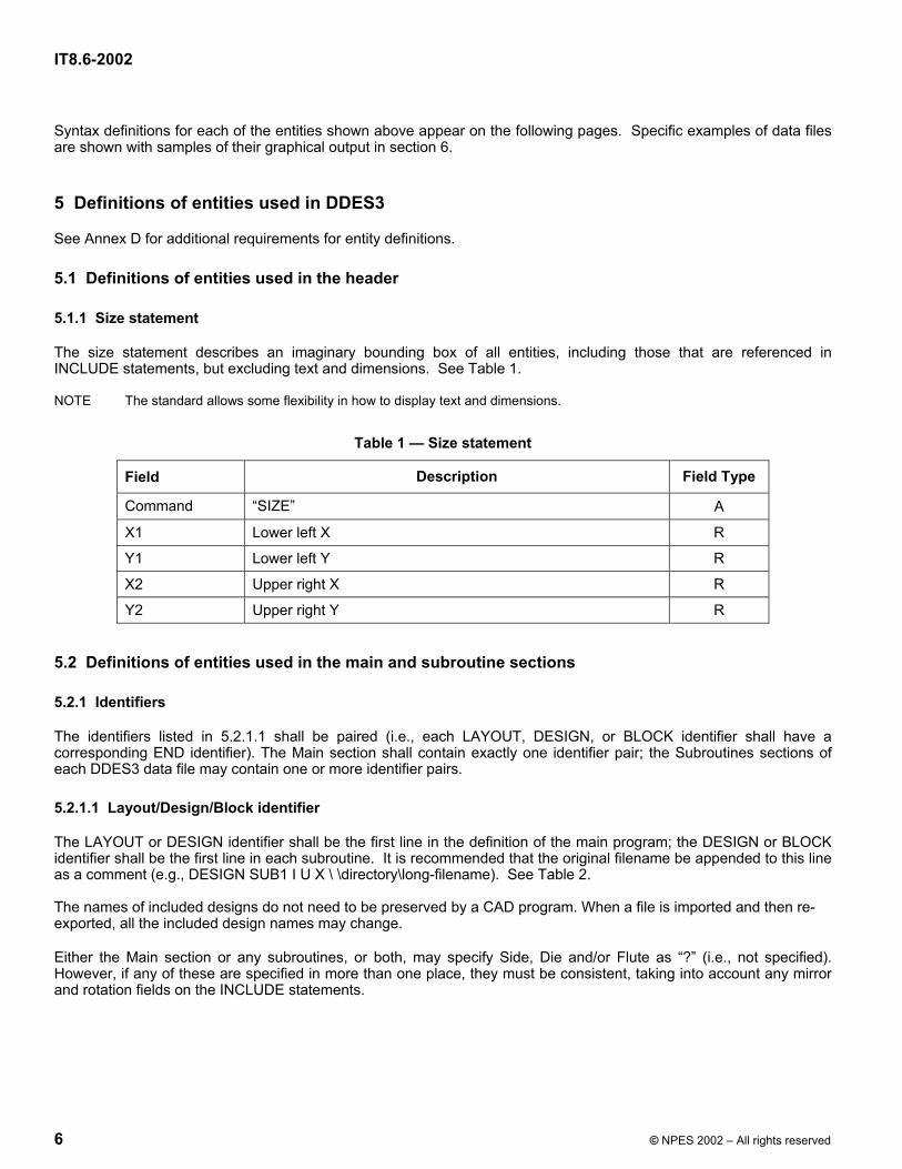
The size statement describes an imaginary bounding box of all entities, including those that are referenced in INCLUDE statements, but excluding text and dimensions. See Table 1.
NOTE The standard allows some flexibility in how to display text and dimensions.
Table 1 — Size statement
Field Description Field Type Command “SIZE” A X1 Lower left X R Y1 Lower left Y R X2 Upper right X R
Y2 Upper right Y R
5.2 Definitions of entities used in the main and subroutine sections
5.2.1 Identifiers
The identifiers listed in 5.2.1.1 shall be paired (i.e., each LAYOUT, DESIGN, or BLOCK identifier shall have a corresponding END identifier). The Main section shall contain exactly one identifier pair; the Subroutines sections of each DDES3 data file may contain one or more identifier pairs.
5.2.1.1 Layout/Design/Block identifier
The LAYOUT or DESIGN identifier shall be the first line in the definition of the main program; the DESIGN or BLOCK identifier shall be the first line in each subroutine. It is recommended that the original filename be appended to this line as a comment (e.g., DESIGN SUB1 I U X \ \directory\long-filename). See Table 2. The names of included designs do not need to be preserved by a CAD program. When a file is imported and then re-exported, all the included design names may change.
Either the Main section or any subroutines, or both, may specify Side, Die and/or Flute as “?” (i.e., not specified). However, if any of these are specified in more than one place, they must be consistent, taking into account any mirror and rotation fields on the INCLUDE statements.
IT8.6-2002
© NPES 2002 – All rights reserved 7
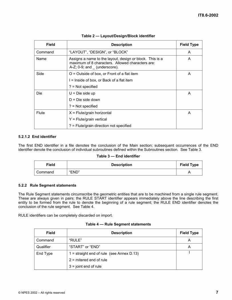
Table 2 — Layout/Design/Block identifier
Field Description Field Type
Command “LAYOUT”, “DESIGN”, or “BLOCK” A
Name Assigns a name to the layout, design or block. This is a maximum of 8 characters. Allowed characters are: A-Z; 0-9; and _ (underscore).
A
Side O = Outside of box, or Front of a flat item I = Inside of box, or Back of a flat item ? = Not specified
A
Die U = Die side up D = Die side down ? = Not specified
A
Flute X = Flute/grain horizontal Y = Flute/grain vertical ? = Flute/grain direction not specified
A
5.2.1.2 End identifier
The first END identifier in a file denotes the conclusion of the Main section; subsequent occurrences of the END identifier denote the conclusion of individual subroutines defined within the Subroutines section. See Table 3.
Table 3 — End identifier
Field Description Field Type
Command “END” A
5.2.2 Rule Segment statements
The Rule Segment statements circumscribe the geometric entities that are to be machined from a single rule segment. These are always given in pairs: the RULE START identifier appears immediately above the line describing the first entity to be formed from the rule to denote the beginning of a rule segment; the RULE END identifier denotes the conclusion of the rule segment. See Table 4.
RULE identifiers can be completely discarded on import.
Table 4 — Rule Segment statements
Field Description Field Type
Command “RULE” A
Qualifier “START” or “END” A
End Type 1 = straight end of rule (see Annex D.13) 2 = mitered end of rule 3 = joint end of rule
I

IT8.6-2002
8 © NPES 2002 – All rights reserved
5.2.3 INCLUDE statement
The INCLUDE statement indicates placement of a subroutine that is defined in the Subroutines section of the file. Placement is done by three coordinate transformations (first mirroring, then rotation, then translation) in a fixed 2-dimensional system.
NOTE This is the same order as DXF, but is not the same order as DDES2 and CFF2.
For nested INCLUDEs the transformations of the inner INCLUDE statement apply first. INCLUDE statements may appear in designs or blocks in the Subroutines section.
Table 5 — INCLUDE statement
Field Description Field Type
Command “INCLUDE” A
Name Name of the subroutine to be placed as a block or design. A
Print Item Name Name of the subroutine used for printing. This should be specified as “–” if not known or not applicable.
A
X Location Denotes the value for the translation of the included object in X direction. R
Y Location Denotes the value for the translation of the included object in Y direction. R
Rotation Rotation of the included object in degrees about the origin of the coordinate system of the block or design. Must be in the range –360 to 360. Positive values = counterclockwise rotation; Negative values = clockwise rotation.
R
X Mirror -1 indicates that the included object has to be mirrored (negated) in the X axis (i.e. about the Y axis) of the block or design. Must be 1 or –1.
I
Y Mirror -1 indicates that the included object has to be mirrored (negated) in the Y axis (i.e. about the X axis) of the block or design. Must be 1 or –1.
I

IT8.6-2002
© NPES 2002 – All rights reserved 9
5.2.4 Geometry entities
Each file shall consist of one or more instances of any of the entities defined in the following tables.
5.2.4.1 Line entity
Table 6 — Line entity
Field Description Field Type Command “LINE” A Layer ID Identifies layer association S12 X Start X coordinate of the start point R Y Start Y coordinate of the start point R X End X coordinate of the end point R Y End Y coordinate of the end point R Line Type Type of the line (see Annex A) I Table Entry Table entry reference number (see Annex D.12) I Pointage Thickness of the line (see Annex D.1) R/A Number of Bridges
Number of bridges on the line (see Annex D.2) I
Bridge Width Width of the bridges, if required (see Annex D.3) R
5.2.4.2 Arc entity Table 7 — Arc entity
Field Description Field Type
Command “ARC” (see D.5) A Layer ID Identifies layer association S12 X Start X coordinate of the start point R Y Start Y coordinate of the start point R X End X coordinate of the end point R Y End Y coordinate of the end point R X Center X coordinate of the center point R Y Center Y coordinate of the center point R Angle Angle subtended at the center or the arc, in degrees
Positive values = counterclockwise arc direction; Negative values = clockwise arc direction
R
Line Type Type of the line (see Annex A) I Table Entry Table entry reference number (see Annex D.12) I Pointage Thickness of the line (see Annex D.1) R/A Number of Bridges
Number of bridges on the line (see Annex D.2) I
Bridge Width Width of the bridges, if required (see Annex D.3) R

IT8.6-2002
10 © NPES 2002 – All rights reserved
5.2.4.3 Circle entity
Table 8 — Circle entity
Field Description Field Type
Command “CIRCLE” A
Layer ID Identifies layer association S12
X Center X coordinate of the center point R
Y Center Y coordinate of the center point R
Radius Radius of the circle Positive values = counterclockwise circle direction; Negative values = clockwise circle direction
Angle Angle from the center to the start position, in degrees R
Line Type Type of the line (see Annex A) I
Table Entry Table entry reference number (see Annex D.12) I
Pointage Thickness of the line (see Annex D.1) R/A
Number of Bridges
Number of bridges on the line (see Annex D.2) I
Bridge Width Width of the bridges, if required (see Annex D.3) R
5.2.4.4 Corner entity
Table 9 — Corner entity
Field Description Field Type
Command “CORNER” (see D.5) A
Layer ID Identifies layer association S12
X Start X coordinate of the start point R
Y Start Y coordinate of the start point R
X End X coordinate of the end point R
Y End Y coordinate of the end point R
X Center X coordinate of the center point R
Y Center Y coordinate of the center point R
Angle Angle subtended at the center or the arc, in degrees Positive values = counterclockwise arc direction; Negative values = clockwise arc direction
R
Line Type Type of the line (see Annex A) I
Table Entry Table entry reference number (see Annex D.12) I
Pointage Thickness of the line (see Annex D.1) R/A

IT8.6-2002
© NPES 2002 – All rights reserved 11
The CORNER entity may optionally be expanded into 3 LINE entities, or replaced by an ARC entity, or both. It takes the identical format to an ARC entity, except that the "Number of Bridges" and "Bridge Width" fields are omitted. The Angle field must be less than or equal to 170. The corner is intended to be treated as a triangle when cutting a laser die, whose sides are defined by two lines tangent to the ends of the implied arc and one side connecting the ends of the arc, and as an arc in other applications. See Figure 1 below, in which the 3 short straights and the arc together make up the corner.
Figure 1 — Corner
5.2.4.5 Bridge entity
This entity is used only for specification of individual, non-standard bridges (see D.2).
Table 10 — Bridge entity
Field Description Field Type
Command “BRIDGE” A
Style C = standard centered bridge L = left-hand tack bridge R = right hand tack bridge D = double-sided tack bridge
A
Position Gives the center of the bridge as a number from 0 – 1 (see Annex D.4)0.0 = start of the line 0.5 = center of the line, etc.
R
Width Width of the bridge (see Annex D.3) R Bridges, in particular non-standard bridges, may be exploded into individual lines and gaps. This is not encouraged and may cause problems with some equipment, especially Rule Benders and Rule Processors.
Bridges that touch the end of the line may be lengthened so that they overlap the end of the line. This is the recommended treatment (to avoid rounding errors), but is not required. The amount of overlap is irrelevant, since it will be discarded by any importing program.
5.2.5 Annotation and Dimension entities
Each file may include one or more of the annotation or dimension entities defined in the following tables.

IT8.6-2002
12 © NPES 2002 – All rights reserved
All dimensions allow the importing program some flexibility in how it chooses to display them. It is preferable to represent a dimension by a single entity, even if this means modifying it slightly to conform to the dimension representation used in the importing program. If the text position lies close to or on the arrow line, the importer has the option of breaking the arrow. If there is insufficient room for the arrows, the importer has the option of reversing them. The only points that should be fixed are the center of the text and the tips of the arrow(s). The importer has the further option of adding a dogleg if the text is not close to the arrow(s).
Dimensions may be exploded into two or more LINE and TEXT entities. The position of arrows and extension lines may be changed.
All DIM entities (e.g., DIMH) and ARROWT shall be followed by a text string, which is identical in format to that following a TEXT entity.
5.2.5.1 Text entity
Table 11 — Text entity
Field Description Field Type
Command “TEXT” (see Annex D.6) A
Layer ID Identifies layer association S12
X Ref X coordinate of the text reference point R
Y Ref Y coordinate of the text reference point R
Size Point size of text R
Rotation Rotation in degrees of text string about the reference point. Must be in the range –360 to 360 Positive values = counterclockwise rotation Negative values = clockwise rotation
R
Justification An integer in range 1-9; indicates position of reference point relative to text string (see Annex D.7)
I
All systems should be able to import (and export unchanged) any character string in a TEXT entity, including Unicode, multi-byte, fractions, and the special symbols for radius, diameter, and degrees. But it is entirely optional how (if at all) these character strings are displayed.
5.2.5.2 Arrow entity
Table 12 — Arrow entity
Field Description Field Type
Command “ARROW” A
Layer ID Identifies layer association S12
X Start X coordinate of the tip of the arrowhead R
Y Start Y coordinate of the tip of the arrowhead R
X End X coordinate of the end of the arrow shaft R
Y End Y coordinate of the end of the arrow shaft R
Arrow length Length of the arrowhead (see Annex D.10) R

IT8.6-2002
© NPES 2002 – All rights reserved 13
5.2.5.3 Arrow with Text entity
Table 13 — Arrow with Text entity
Field Description Field Type
Command “ARROWT” A
Layer ID Identifies layer association S12
X Start X coordinate of the tip of the arrowhead R
Y Start Y coordinate of the tip of the arrowhead R
X End X coordinate of the end of the arrow shaft R
Y End Y coordinate of the end of the arrow shaft R
X Text X coordinate of the center of the text R
Y Text Y coordinate of the center of the text R
Arrow length Length of the arrowhead R
Size Point size of the text R
Justification An integer in range 1-9; indicates position of reference point relative to text string (see Annex D.7)
I
5.2.5.4 Linear Dimension with Horizontal Text entity
The text included with this Dimension entity is oriented parallel to the X-axis of the drawing.
Table 14 — Linear Dimension with Horizontal Text entity
Field Description Field Type
Command “DIMH” A
Layer ID Identifies layer association S12
X Start X coordinate of the start point R
Y Start Y coordinate of the start point R
X End X coordinate of the end point R
Y End Y coordinate of the end point R
X Text X coordinate of the center of the text (see Annex D.8) R
Y text Y coordinate of the center of the text R
Size Point size of the dimension text (see Annex D.11) R
Extension at start Length of extension line that extends to start of line (see Annex D.9) R
Extension at end Length of extension line that extends to end of line (see Annex D.9) R
IT8.6-2002
14 © NPES 2002 – All rights reserved
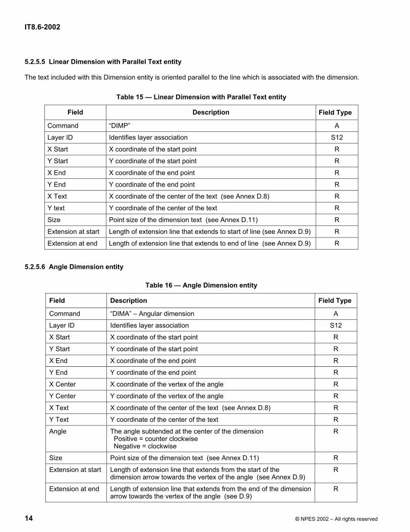
5.2.5.5 Linear Dimension with Parallel Text entity
The text included with this Dimension entity is oriented parallel to the line which is associated with the dimension.
Table 15 — Linear Dimension with Parallel Text entity
Field Description Field Type
Command “DIMP” A
Layer ID Identifies layer association S12
X Start X coordinate of the start point R
Y Start Y coordinate of the start point R
X End X coordinate of the end point R
Y End Y coordinate of the end point R
X Text X coordinate of the center of the text (see Annex D.8) R
Y text Y coordinate of the center of the text R
Size Point size of the dimension text (see Annex D.11) R
Extension at start Length of extension line that extends to start of line (see Annex D.9) R
Extension at end Length of extension line that extends to end of line (see Annex D.9) R
5.2.5.6 Angle Dimension entity
Table 16 — Angle Dimension entity
Field Description Field Type
Command “DIMA” – Angular dimension A
Layer ID Identifies layer association S12
X Start X coordinate of the start point R
Y Start Y coordinate of the start point R
X End X coordinate of the end point R
Y End Y coordinate of the end point R
X Center X coordinate of the vertex of the angle R
Y Center Y coordinate of the vertex of the angle R
X Text X coordinate of the center of the text (see Annex D.8) R
Y Text Y coordinate of the center of the text R
Angle The angle subtended at the center of the dimension Positive = counter clockwise Negative = clockwise
R
Size Point size of the dimension text (see Annex D.11) R
Extension at start Length of extension line that extends from the start of the dimension arrow towards the vertex of the angle (see Annex D.9)
R
Extension at end Length of extension line that extends from the end of the dimension arrow towards the vertex of the angle (see D.9)
R
IT8.6-2002
© NPES 2002 – All rights reserved 15
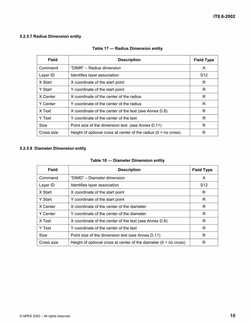
5.2.5.7 Radius Dimension entity
Table 17 — Radius Dimension entity
Field Description Field Type
Command “DIMR” – Radius dimension A
Layer ID Identifies layer association S12
X Start X coordinate of the start point R
Y Start Y coordinate of the start point R
X Center X coordinate of the center of the radius R
Y Center Y coordinate of the center of the radius R
X Text X coordinate of the center of the text (see Annex D.8) R
Y Text Y coordinate of the center of the text R
Size Point size of the dimension text (see Annex D.11) R
Cross size Height of optional cross at center of the radius (0 = no cross) R
5.2.5.8 Diameter Dimension entity
Table 18 — Diameter Dimension entity
Field Description Field Type
Command “DIMD” – Diameter dimension A
Layer ID Identifies layer association S12
X Start X coordinate of the start point R
Y Start Y coordinate of the start point R
X Center X coordinate of the center of the diameter R
Y Center Y coordinate of the center of the diameter R
X Text X coordinate of the center of the text (see Annex D.8) R
Y Text Y coordinate of the center of the text R
Size Point size of the dimension text (see Annex D.11) R
Cross size Height of optional cross at center of the diameter (0 = no cross) R

IT8.6-2002
16 © NPES 2002 – All rights reserved
6 DDES3 file code examples and diagrams
DDES3.0ISIZE 0.0 0.0 3.0 2.0DESIGN DIAGRAM1 I U ?LINE A 0.0 0.0 3.0 0.0 101 0 P2 0LINE A 3.0 0.0 3.0 2.0 101 0 P2 0LINE A 3.0 2.0 0.0 2.0 101 0 P2 0LINE A 0.0 2.0 0.0 0.0 101 0 P2 0LINE A 0.0 1.75 3.0 1.75 101 0 P2 0DIMH DIMENSIONS -1.5 0.0 -1.5 2.0 -1.5 1.0 31 1.4 1.42DIMP DIMENSIONS 4.0 2.0 4.0 0.0 4.0 1.0 31 0.9 0.92DIMH DIMENSIONS 0.77 2.0 0.77 1.75 1.27 1.19 31 0.0 0.01/4ENDEOF
214/
Extension length 2
Extension length 1
Pos. lengthNeg. length
Dimension end
Dimension start
NOTE The DIMH dimension on the left starts at the bottom, so the positive extensions are on its right, while the DIMP dimension on the right starts at the top, so the positive extensions are on its left. The ¼ inch dimension has an optional dogleg added to join the text to the arrows.
Example 1

IT8.6-2002
© NPES 2002 – All rights reserved 17
DDES3.0ISIZE 0.0 0.0 2.0 2.0DESIGN DIAGRAM2 I U ?LINE A 0.0 0.0 2.0 0.0 101 0 P2 0LINE A 2.0 0.0 2.0 2.0 101 0 P2 0LINE A 2.0 2.0 0.0 0.0 101 0 P2 0DIMA DIMENSIONS 2.8284 0.0 2.0 2.0 0.0 0.0 2.68 1.0 45.0 30 0.72 0.045{O}ENDEOF
45º
Extension length 1
Pos.length
Neg.length
Dimension start
Dimension end
Extension length 2 ( = 0 )
NOTE The start extension extends towards the vertex of the angle being dimensioned, so it is positive. The end extension has a length of 0.
Example 2
IT8.6-2002
18 © NPES 2002 – All rights reserved
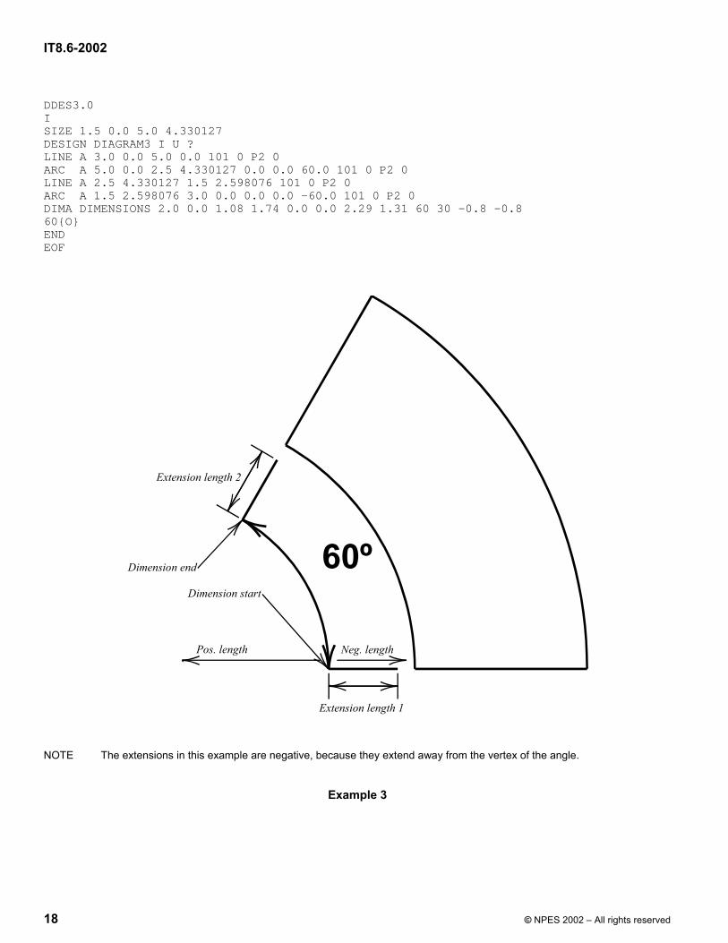
DDES3.0ISIZE 1.5 0.0 5.0 4.330127DESIGN DIAGRAM3 I U ?LINE A 3.0 0.0 5.0 0.0 101 0 P2 0ARC A 5.0 0.0 2.5 4.330127 0.0 0.0 60.0 101 0 P2 0LINE A 2.5 4.330127 1.5 2.598076 101 0 P2 0ARC A 1.5 2.598076 3.0 0.0 0.0 0.0 -60.0 101 0 P2 0DIMA DIMENSIONS 2.0 0.0 1.08 1.74 0.0 0.0 2.29 1.31 60 30 -0.8 -0.860{O}ENDEOF
NOTE The extensions in this example are negative, because they extend away from the vertex of the angle.
Example 3
60º
Extension length 2
Dimension end
Dimension start
Pos. length Neg. length
Extension length 1

IT8.6-2002
© NPES 2002 – All rights reserved 19
DDES3.0ISIZE –2.0 –2.0 2.0 5.0DESIGN DIAGRAM4 I U ?CIRCLE A 0.0 0.0 2.0 0.0 101 0 P2 0DIMD DIMENSIONS 1.43 1.41 0.0 0.0 0.71 0.71 30 04CIRCLE A 0.0 4.0 1.0 0.0 101 0 P2 0DIMD DIMENSIONS 0.74 4.72 0.0 4.0 2.01 5.14 30 0.22ENDEOF
Example 4
2
4
Text position
Dimension start
Dimension start
Text position
Center
Center ( cross size = 0 )

IT8.6-2002
20 © NPES 2002 – All rights reserved
DDES3.0ISIZE 1.3536 –1.3536 3.4896 4.0496DESIGN DIAGRAM5 I U ?ARC A 1.7794 -1.3536 1.3536 1.7794 0.0 0.0 90.0 101 0 P2 0ARC A 1.7370 3.2223 3.4272 2.8477 2.6126 3.1726 -198.4957 101 0 P2 0DIMR DIMENSIONS 2.0611 0.8662 0.0 0.0 1.1181 -0.1102 30 0.42.2357DIMR DIMENSIONS 1.7642 3.3946 2.6126 3.1726 0.8219 2.5659 30 0.00.8770ENDEOF
Example 5
0.8770
2.2357
Dimension start
Text position
Center ( cross size = 0 )
Dimension start
Text position
Center

IT8.6-2002
© NPES 2002 – All rights reserved 21
DDES3.0I
SIZE -3.0 -4.0 6.0 2.0LAYOUT DIAGRAM6 I U ?INCLUDE JOBA PI1 0.0 0.0 0.0 1 1INCLUDE JOBA PI1 -2.0 -4.0 30.0 1 1INCLUDE JOBA PI2 5.0 -4.0 -30.0 -1 1ENDDESIGN JOBA ? ? ?LINE A 0.0 0.0 3.0 0.0 101 0 P2 0LINE A 3.0 0.0 3.0 1.5 101 0 P2 0ARC A 3.0 1.5 2.5 2.0 2.5 1.5 90.0 101 0 P2 0LINE A 2.5 2.0 0.0 2.0 101 0 P2 0LINE A 0.0 2.0 0.0 0.0 101 0 P2 0INCLUDE JOBB - 0.5 1.0 15.0 1 1INCLUDE JOBB - 2.5 0.5 -15.0 -1 1ENDBLOCK JOBB ? ? ?LINE A 0.0 0.0 1.0 0.0 101 0 P2 0LINE A 1.0 0.0 1.0 0.5 101 0 P2 0LINE A 1.0 0.5 0.0 0.0 101 0 P2 0ENDEOF
Example 6
X AXIS
Y AXIS
IT8.6-2002
22 © NPES 2002 – All rights reserved
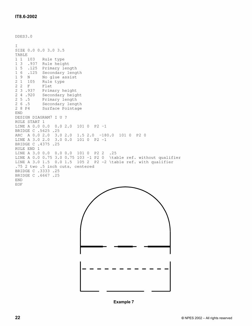
DDES3.0
ISIZE 0.0 0.0 3.0 3.5TABLE1 1 103 Rule type1 3 .937 Rule height1 5 .125 Primary length1 6 .125 Secondary length1 9 N No glue assist2 1 105 Rule type2 2 F Flat2 3 .937 Primary height2 4 .920 Secondary height2 5 .5 Primary length2 6 .5 Secondary length2 8 P4 Surface PointageENDDESIGN DIAGRAM7 I U ?RULE START 1LINE A 0.0 0.0 0.0 2.0 101 0 P2 -1BRIDGE C .5625 .25ARC A 0.0 2.0 3.0 2.0 1.5 2.0 -180.0 101 0 P2 0LINE A 3.0 2.0 3.0 0.0 101 0 P2 -1BRIDGE C .4375 .25RULE END 1LINE A 3.0 0.0 0.0 0.0 101 0 P2 2 .25LINE A 0.0 0.75 3.0 0.75 103 -1 P2 0 \table ref. without qualifierLINE A 3.0 1.5 0.0 1.5 105 2 P2 -2 \table ref. with qualifier.75 2 two .5 inch cuts, centeredBRIDGE C .3333 .25BRIDGE C .6667 .25ENDEOF
Example 7

IT8.6-2002
© NPES 2002 – All rights reserved 23
Annex A (normative)
Line types
A conforming program should be able to import a file containing any line type in the range 0-999. When re-exporting the file, it is acceptable (if there is no alternative) to change any line type in the 1-99 range to 0, or any in the range 101-149 to 100, or any in the range 151-199 to 150, or any in the range 201-299 to 200, etc. As a last resort, it is allowed to change any line type in the range 100-999 to 900. Note that changing a line type to a different (non-miscellaneous) type shall not be allowed, nor is changing from a line type in one range to a miscellaneous line type corresponding to another range.
CGATS or the IADD committee may define new line types from time to time. Unless such a line type has been defined, its use shall not be permitted in a DDES3 file, except for those in the range 800-899 (which can be freely used by mutual agreement between any customers, as desired). When importing a file, any unrecognized line type should be assumed to be one newly defined by CGATS or the IADD committee, and should be treated the same as the corresponding Miscellaneous line type (e.g. 347 should be treated as 300).
0-99 Annotation Lines (not cut/routed/etc. by NC machine) 0 Miscellaneous annotation lines (type of product unknown) 1 Miscellaneous annotation lines related to dies 2 Miscellaneous annotation lines related to counters 3 Miscellaneous annotation lines related to strippers 4 Miscellaneous annotation lines related to blankers (presser bar edges, etc.) 5 Miscellaneous annotation lines related to rubber 10 Crosses 11 Print bleed 12 Non-varnish / UV area 13 Actual sheet edge 14 Usable sheet edge 15 Printing / UV Blanket Edge 16 Zipper / Tear Strip / Tear Edge - reference lines for cutting edge 17 Wave / Scallop - reference lines for cutting edge 18 Punches - reference lines for center / cutting edge 80-89 User-defined 100-199 Line types for Dies 100 Miscellaneous ruled lines for dies 101 Knife / Cutting rule 102 Crease / Scoring rule 103 Perforation (Alternating cutting and spaces) 104 Cutscore / Halfcut (Partial depth cutting rule) 105 Cut-Crease rule (Alternating cutting and creasing rule) 106 Cutscore-Crease (Alternating partial depth cutting and creasing rule) 107 Reverse cutscore / halfcut (for anvil in die) 108 Emboss / Deboss crease profile 109 Zipper / Tear Strip / Tear Edge - machined shape to hold rule 110 Wave / Scallop – machined shape to hold rule 111 Punches – machined shape to hold punch 112 Stripping / Scrap knives 113 Chopper knives (e.g. 3 x 3 inch grid) 114 Carrier rule 115 Balance / leveling knives 116 Press Gripper fingers
IT8.6-2002
24 © NPES 2002 – All rights reserved
150 Miscellaneous non-ruled (machined) lines (floats, handholes, etc.) 151 Dieboard edge 152 Nick locations 153 Chase registration holes 154 Counter registration holes 155 Bridge depression lines 198 Full cut name / ID 199 Scribed/Etched name / ID
200-299 Line types for Counters 200 Miscellaneous (machined) lines for counters 201 Crease Channel 1, with (parallel to) grain / flute 202 Crease Channel 2, against (perpendicular to) grain / flute 203 Register holes / end of crease treatment (non end-mill, circular cut) 204 Cutout tool, e.g. 120 degree 205 Chamfer / Skive tool, e.g. 170 degree 206 Full depth cutting on Crease Channel 1 207 Full depth cutting on Crease Channel 2 208 Cutout Tool, auxiliary profile using different height / tool 209 Chamfer Tool, auxiliary profile using different height / tool 210 Register holes (end mill tool, single plunge) 211 Solvent cutouts – Register Hole / end of crease treatment tool 212 Solvent cutouts – Cutout Tool 213 Milled lines, e.g. emboss / deboss 214 Milled lines, perimeter cleanup profile 298 Full cut name / ID 299 Partial cut name / ID 300-399 Line types for Strippers 300 Miscellaneous (machined) lines for strippers 301 Female / Lower internal cutouts 302 Female / Lower external profile 303 Guillotine / Separator external profile 305 Mounting holes (Easyset, Cross bars, Rails, etc.) 306 Wooden buildup / shelf profiles 307 Carrier rule mounting cuts 308 Spacer pin center hole 309 Bar breaker attachment mounting cuts 310 Vacuum / Vent holes 311 Male / Upper pins or rule 312 Male / Upper board outside edge 398 Full cut name / ID 399 Partial cut name / ID 400-499 Line types for Blankers 400 Miscellaneous (machined) lines for blankers (presser bar holes, bar alignment holes, etc.) 401 Female / Lower cavity profile 402 Male / Upper pusher profile 403 Backer / Support plate cavity profile 404 Vacuum / Vent holes 405 Spacer pin center hole 406 Female / Lower board outside edge 407 Male / Upper board outside edge 408 Backer / Support plate outside edge 498 Full cut name / ID 499 Partial cut name / ID

IT8.6-2002
© NPES 2002 – All rights reserved 25
500-599 Line types for Ejection Rubber 500 Miscellaneous (machined) lines for rubber 501 Ejection rubber profile 598 Full cut name / ID 599 Partial cut name / ID 800-899 User Defined 900-999 Miscellaneous Machined Lines (type of product unknown) 900 Miscellaneous (machined) lines 998 Full cut name / ID 999 Partial cut name / ID
IT8.6-2002
26 © NPES 2002 – All rights reserved
Annex B (normative)
Table parameters
The following parameters are available for use in table entries:
1 <Line Type> value or comment representing the rule type 2 <Type of Rule> F for Flat, R for Rotary (defaults to F if omitted) 3 <Height of Primary Rule> value representing height of rule or ejection rubber (or primary rule
type for combination rules) 4 <Height of Secondary Rule> value representing height of secondary rule type (crease) for
combination rules 5 <Length of Primary Rule> value representing length of tooth in perforation rule, cut or cutscore
rule in combination rules 6 <Length of Secondary Rule> value representing land (untoothed) length in perforation rule, or
length of crease in combination rules 7 <Type of Bevel> C for center, S for side (defaults to C if omitted) 8 <Surface Pointage> value representing creasing surface (e.g. value of P4 for this
parameter on a 2 point line indicates a 2-point rule that widens to a creasing edge of 4 points); see Annex D.1.
9 <Glue Assist> G for glue assist, N for no glue assist (defaults to N if omitted) 10 <Surface Taper> value representing degree of taper from base to surface (defaults to 0
[vertical] if omitted)
Parameter # 1 is required. The remaining parameters are optional. The line type (Parameter #1) will determine which of these parameters may be included in a given table entry. The available parameters for each line type are shown below:
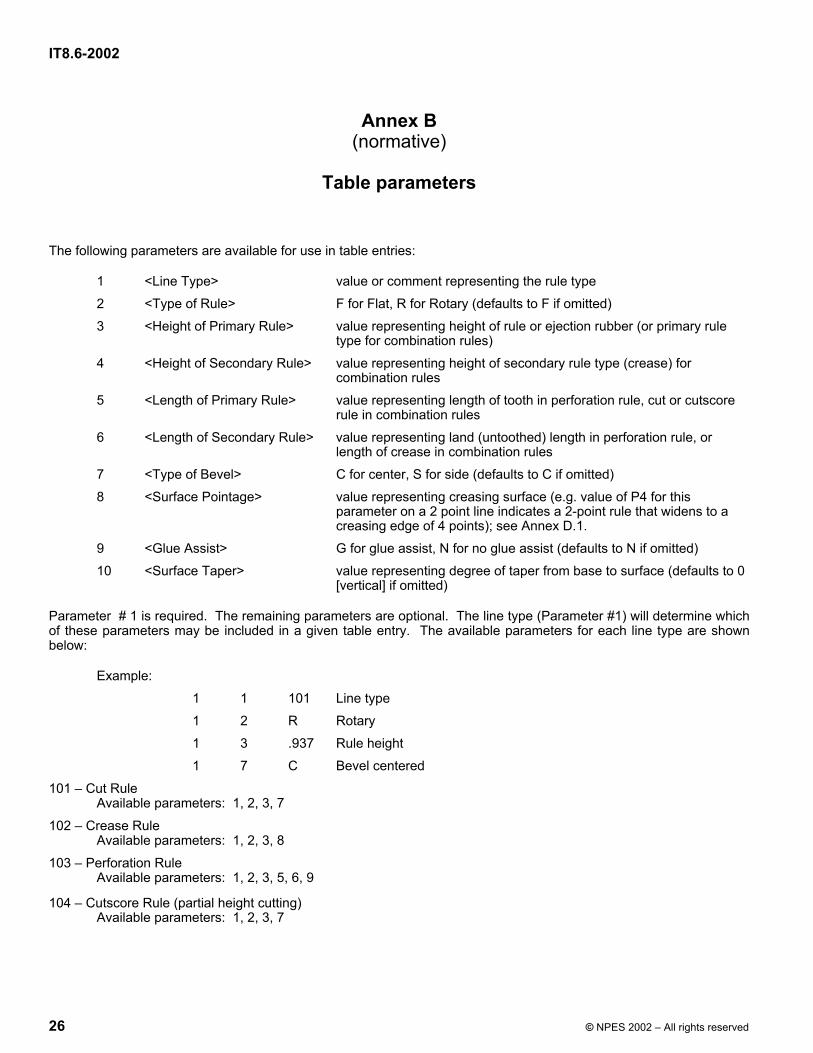
Example: 1 1 101 Line type 1 2 R Rotary 1 3 .937 Rule height 1 7 C Bevel centered
101 – Cut Rule Available parameters: 1, 2, 3, 7
102 – Crease Rule Available parameters: 1, 2, 3, 8
103 – Perforation Rule Available parameters: 1, 2, 3, 5, 6, 9
104 – Cutscore Rule (partial height cutting) Available parameters: 1, 2, 3, 7

IT8.6-2002
© NPES 2002 – All rights reserved 27
105 – Combination Cut / Crease Rule Available parameters: 1, 2, 3, 4, 5, 6 The cut is the primary rule; the crease is the secondary rule
106 – Combination Cutscore / Crease Rule Parameters used: 1, 2, 3, 4, 5, 6 The cutscore is the primary rule; the crease is the secondary rule
109 – Zipper rule Parameters used: 1, 2, 3, 9
110 – Wave Rule Parameters used: 1, 2, 3, 9
501 – Ejection rubber Parameters used: 1, 3, 10

IT8.6-2002
28 © NPES 2002 – All rights reserved
Annex C (normative)
Table reference qualifiers
Line types 103 (perforation), 105 (cut/crease), and 106 (cutscore/crease) shall start with 2 parameters as follows:
Parameter #1 – if positive, this indicates the distance from the start of the line to the first tooth / cut / cutscore. If negative, this indicates the distance from the end of the line to the first tooth / cut / cutscore.
Parameter #2 – if positive, this indicates the number of teeth or cut / cutscore segments. If 0, the line will be filled with teeth or cut / cutscore segments.
Any additional information on these line types is treated as a comment.
For other line types, the entire table reference qualifier is treated as a comment.

IT8.6-2002
© NPES 2002 – All rights reserved 29
Annex D (normative)
Additional requirements for entity definitions
D.1 Pointage
Pointage is a printer’s unit of measurement, where approximately 72 points = 1 inch. In this standard, where pointage is used to indicate the thickness of LINE, ARC, CIRCLE and CORNER entities, 1 point = 0.014 inches (0.3556 mm). For DDES3 files, pointage is expressed either as a real number, in the same units as the coordinates, or as P followed by an integer.
NOTE For example, if working in inches, 0.028 and P2 would mean the same. If working in metric, 1.07, being 1.0668 rounded to 2 places, and P3 would mean the same thing.).
The use of P is recommended whenever the meaning is “use the rule width that is nominally called 2 point”, especially when working in metric units.
D.2 Number of Bridges parameter
The Number of Bridges parameter may be:
0: no bridges on this line.
A positive integer: standard bridge type and placement, using the width specified in Bridge Width. For a line with N bridges, the line is divided into N equal segments, and a bridge is placed at the center of each segment.
A negative integer: non-standard bridge placement and/or bridge type. A parameter of –N in the Number of Bridges field indicates that N non-standard bridges are defined on the following lines. See 5.2.4.5 Bridge Entity for further details.
If a line is followed by both a table qualifier and bridge entities, the table qualifier will appear first.
D.3 Bridge Width parameter
The Bridge Width parameter is the distance the cutting device will move between the two adjacent cut lines. The board remaining after laser cutting will thus be slightly smaller than this value (i.e. the bridge width value minus the pointage used for cutting the adjacent lines). The Bridge Width parameter shall not be included for any element which has a #bridges parameter that is 0 or a negative integer.
D.4 Position parameter
Any portion of a bridge that lies beyond the end of the line shall be ignored.

IT8.6-2002
30 © NPES 2002 – All rights reserved
D.5 ARC and CORNER entities
The ARC and CORNER entities are over-defined for two reasons:
a) to make it easier for a human to decipher the file;
b) to help the CAD system to distinguish between very short arcs (subtended angle close to 0) and almost full circles (subtended angle close to 360).
Where there are conflicts due to rounding errors, the importing program should make whatever changes are necessary to yield the least possible overall change to the arc values. In general, the order of priorities is:
1) Start + End points; 2) Center point; 3) Angle.
D.6 TEXT command
Following the TEXT command, the text string shall be defined on the next lines. A single line of text shall appear on one line. Multi-line text shall appear on multiple lines (one line in the file for one line in the text string). Comments shall not be allowed on the text lines. The maximum number of characters in a text string (on all lines combined) shall be 255. Any trailing blanks on the lines shall be ignored. Within a text string, the following character sequences have special meaning:
{3+5/32} Braces are used to define a fraction, which will preferably be displayed as 35/32
{R} This defines a radius symbol (e.g., 3{R} might output as 3R)
{D} This defines a diameter symbol (e.g., 4{D} might output as 4 or 4 DIA)
{O} Uppercase “o” (not zero) in braces defines a degree symbol (e.g., 75{O} outputs as 75°)
\{ This represents the character { \\ This represents a single \
\xx This represents a single character whose ASCII code is given by the hexadecimal number xx.
\ At the end of the line, this indicates a new line in the text string.
\xx This represents a single character whose ASCII code is given by the hexadecimal number xx. This must be used for any character that is not in the range 32-126. For characters in the range 127-255, the importer has the option to interpret them either using the PD-8 symbol set, or as the first byte of a 2-byte character (e.g., a Japanese Kanji character).
NOTE The following are examples:
{1/2}{R} ½ R 123\31\32\33 123123 ABC\\DEF\{GHI ABC\DEF{GHI
LINE 1\ LINE 1 LINE 2 LINE 2

IT8.6-2002
© NPES 2002 – All rights reserved 31
D.7 Text justification codes
The following text justification codes shall be as defined below: 1 = bottom left 2 = middle left 3 = top left 4 = bottom center 5 = middle center 6 = top center 7 = bottom right 8 = middle right 9 = top right
D.8 Text in dimensions
Text in dimensions shall always be center justified.
D.9 Extension length
If the extension length is 0, there is no extension line. If the extension length is non-zero, the importer has the option of adding a short reverse extension.
The sign of the extension length shall be as follows:
for DIMH or DIMP - positive extends to the right of the dimension (moving from start to end), negative extends to the left of the dimension.
for DIMA - positive extends towards the vertex of the angle, negative extends away from the vertex of the angle.
D.10 Simple dimension line
Use an arrow with length = 0 to create a simple dimension line.
D.11 Use of arrow head for dimensions
The length of the arrow head for dimensions may be determined by the importing program. One suggested implementation is to set the arrow length equal to the point size of the text.
D.12 Table entry reference number
The Table entry reference number shall be a required parameter. If the entity does not reference a table entry, then the value in this field shall be 0. A negative number references the table entry given by <absolute value of integer> (e.g., -3 references table entry 3). A positive integer references the given table entry, and also has a table qualifier on the next line. Table qualifiers are defined in Annex C.
D.13 Rule Segment identifier pairs
The rule processing information given by the Rule Segment identifier pairs is primarily intended for interpretation and use by automated rule processing machinery; thus, CAD programs importing this information need not be able to interpret this data.