greybot v - greyrobotics.in · 5.9 line follower sensor – array of 6 analog line follower sensor...
TRANSCRIPT

www.greyrobotics.in
1
www.greyrobotics.in
GREYBOT V.1 ATMEGA 16 BASED ROBOTIC PLATFORM
USER MANUAL
Designed by:

www.greyrobotics.in
2
www.greyrobotics.in
INDEX
Sr.No Content Page No.
1. Product Description 4
2. Features 5
3. Technical Specifications
3.1 Micrcontroller
3.2 Programming
3.3 Indicators
3.4 Locomotion
3.5 Power
3.6 Sensors
3.7 Operational Modes
3.8 Communication
3.9 Dimensions
3.10 Software Support
6
4. Block Diagram 8
5. Using GreyBot V1.0
5.1 Powering Up GreyBot
5.2 Power Management System on GreyBot
5.3 Regulated Supply for onboard payload
5.4 Battery Charging Procedure
5.5 Motion Control
5.6 PWM for Velocity Control
5.7 Micocontroller Pin Connections
5.8 Infrared Proximity Sensor
5.9 Line Follower Sensor
5.10 LCD Interfacing
5.11 User Programmable Pins
9

www.greyrobotics.in
3
www.greyrobotics.in
5.11.1 LED’s
5.11.2 Buzzer
5.11.3 Swi0tches
5.12 Battery Voltage Swing
6. Optional Interfaces
6.1 Servo Motor
6.2 Ultrasonic Sensor
6.3 Combination of Servo Motor and Ultrasonic Sensor
6.4 Magnetometer Interface
6.5 Bluetooth Module Interface
18
7. Contact 21

www.greyrobotics.in
4
www.greyrobotics.in
1. Product Description
GreyBot V.1 is a low-cost robot designed by GreyRobotics that will help you get acquainted with
robotics and embedded system platform. With its unique software and hardware design, you will
be able to design and run various robotic based applications both simple and complex. It is a
versatile platform created for the use of beginners as well as researchers so as to ease their work.
Hobbyists and enthusiasts can earn expertise in robotics by developing algorithms and test them
on GreyBot. Its architecture allows you to control the robot using AVR microcontroller. It is
powered using high performance, rechargeable Lithium Ion battery of 3.7V/2.5A rating. Auto cut-
off battery charger is provided for charging the robot. It comes along with our easy to use Line
Follower Sensor Array which can be used for developing the path following algorithm for the bot.
Long distance Infrared Proximity Sensor is provided. High speed motors help you to give the robot
its locomotion. Motor control is achieved using H-bridge motor driver. The onboard 16x2
alphanumeric display along with user switches can be used to select various operating modes of
the robot. Also, it has user programmable LED’s and buzzer.
The robot has additional pins to interface Magnetometer, Ultrasonic Sensor, Servo Motor and
Bluetooth module as per the user application. We also provide an inbuilt firmware for basic testing
and functioning of the robot. The robot can be programmed using ISP port.

www.greyrobotics.in
5
www.greyrobotics.in
2. Features
▪ Comes along with a Line Follower Sensor Array of 6 developed by GreyRobotics for
path following application.
▪ Long Distance IR Proximity Sensor for obstacle detection
▪ Two user programmable LED’s.
▪ Two user programmable Switches.
▪ User programmable buzzer as audio output device.
▪ LCD display for easy user access.
▪ On board motor driver.
▪ User accessible PWM pins for speed control of motor
▪ Lithium Ion battery with auto cut-off charger.
▪ ISP port for programming.
▪ Direct plugin HC-05 Bluetooth facility (optional).
▪ Pins available for interfacing of Magnetometer, Servo Motor and Ultrasonic Sensor
(optional).
▪ Easy to mount slot for Servo Motor (optional).
www.greyrobotics.in
6
www.greyrobotics.in
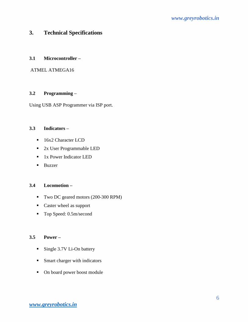
3. Technical Specifications
3.1 Microcontroller –
ATMEL ATMEGA16
3.2 Programming –
Using USB ASP Programmer via ISP port.
3.3 Indicators –
▪ 16x2 Character LCD
▪ 2x User Programmable LED
▪ 1x Power Indicator LED
▪ Buzzer
3.4 Locomotion –
▪ Two DC geared motors (200-300 RPM)
▪ Caster wheel as support
▪ Top Speed: 0.5m/second
3.5 Power –
▪ Single 3.7V Li-On battery
▪ Smart charger with indicators
▪ On board power boost module

www.greyrobotics.in
7
www.greyrobotics.in
3.6 Sensors –
• IR Proximity Sensor
• Line Follower sensor array 6 developed by GreyRobotics
• Ultrasonic range sensors (Optional)
• Magnetometer (Optional)
3.7 Operational Modes –
▪ Test Mode
▪ Line follower mode
▪ Standalone (Autonomous Control)
▪ Distributed (multi robot communication)
3.8 Communication –
▪ Bluetooth module.
▪ USB to TTL for serial communication.
3.9 Dimensions –
▪ 140x130x100 mm
3.10 Software Support –
▪ Compiler - ATMEL Studio, WINAVR
▪ Burner - AVRDudess
www.greyrobotics.in
8
www.greyrobotics.in
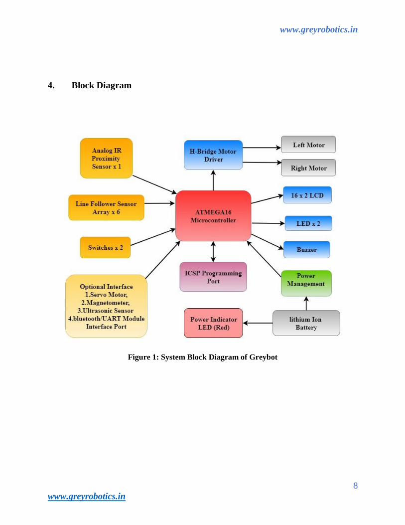
4. Block Diagram
Figure 1: System Block Diagram of Greybot

www.greyrobotics.in
9
www.greyrobotics.in
5. USING GREYBOT V1.0
Figure 2: Top View
Figure 3: Bottom View

www.greyrobotics.in
10
www.greyrobotics.in
5.1 Powering up Greybot –
Greybot is powered by 18650 series single cell lion rechargeable battery. Battery has 3.7volt and
2.5Ah capacity. For safety during transportation, robot’s battery connector is disconnected.
Connect battery to the connector. Before connecting the battery pack or inserting 2 pin relimate
connector in the given socket, make sure that the Power Switch of the robot is off. You need to
charge the battery before your first use. Use the charging module provided along with the robot
accessories. Refer to the battery charging procedure section of the manual.
5.2 Power management system on the Greybot –
Greybot is powered by using a single cell li-ion rechargeable battery. When it is fully discharged
voltage drops to about 3V. Battery pack should not be discharged below 2.8V. Power management
block on the Greybot performs following functions:
1. Regulated supply for onboard payload.
2. Battery charging when robot is powered off and when external battery charger is connected.
5.3 Regulated supply for onboard payload –
Switching regulated technique is used to provide power supply to the GreyBot. It performs boost
regulation to get a constant output voltage irrespective of any changes in the input supply voltage.
It boosts up the battery voltage to 8.2V and then using a linear regulator this voltage is stepped
down to 5V.
5V System: Powers microcontroller, logic circuit and sensors.
8.2V System: Powers Motor driver.

www.greyrobotics.in
11
www.greyrobotics.in
5.4 Battery Charging Procedure –
Before connecting the battery pack or inserting the 2 pin relimate connector in the socket provided,
make sure that the power Switch of the robot is off. You need to charge the battery before its first
use. Use charging module provided along with the robot accessories. Connect its one end to the
charging port of the robot and the other end to the USB terminal of a laptop or computer.
The battery status can be monitored through the status LED of the charging module (TP4050)
which switches from RED to YELLOW on full charge. On full-charge, it will automatically cut
off the supply from the charger. GreyBot is now ready to run!
5.5 Motion control –
Greybot comes with 250 RPM DC geared motors in differential drive configuration along with a
caster wheel for support. Robot has a top speed of about 0.5m per second. Using this configuration,
the robot can turn with zero turning radius by rotating one wheel in clockwise direction and other
in counterclockwise direction. Robot’s motors have built-in clutch for protection of the motor’s
gears from non-continuous wheel stalling. Motion control involves direction control and velocity
control. Motors are controlled by L293D Dual motor driver which can provide up to 600mA of
current to each motor. To change the Direction of the motor, appropriate logic levels (High/Low)
are applied to L293D’s direction Control pins. Velocity control is done using Pulse Width
Modulation (PWM).

www.greyrobotics.in
12
www.greyrobotics.in
5.6 Pulse Width Modulation for velocity control –
Pulse width modulation is a process in which duty cycle of constant frequency square wave is
Modulated to control power delivered to the load i.e. motor. Duty cycle is the ratio of ‘T-ON/ T’.
Where ‘T-ON’ is ON time and ‘T’ is the time period of the Wave. Power delivered to the motor
is proportional to the ‘T-ON’ time of the signal. In case of PWM the motor reacts to the time
average of the signal. PWM is used to control total amount of power delivered to the load without
power losses which generally occur in resistive methods of power control.
Figure 4: Pulse Width Modulation (PWM)
Above figure shows the PWM waveforms for motor velocity control. In case (A), ON time is
90% of time period. This wave has more average value. Hence more power is delivered to the
Motor. In case (B), the motor will run slower as the ON time is just 10% of time period. In the
figure 3.10 area marked with the red border are the LEDs connected to the input stage of
The L293D motor driver. Area marked by Blue border shows LEDs connected to the output of
The motor driver. Orange border marks position encoder output LEDs. Yellow border marks left
And right motor connectors.

www.greyrobotics.in
13
www.greyrobotics.in
5.7 Microcontroller pin connections –
Microcontroller Pin Function
Microcontroller
Pin
Function
PB3(OC0) Pulse width modulation for the left motor (velocity control)
PD7(OC2) Pulse width modulation for the right motor (velocity control)
PC4 Left motor direction control
PC5 Left motor direction control
PC6 Right motor direction control
PC7 Right motor direction control
Table 1: Motor Pin functionality
DIRECTION LEFT
PC4
LEFT
PC5
RIGHT
PC6
RIGHT
PC7
PWM
PB3- PD7
FORWARD 1 0 0 1 As per velocity
requirement
REVERSE 0 1 1 0 As per velocity
requirement
LEFT (Left Motor Forward, Right
Motor Stop)
0 0 0 1 As per velocity
requirement
RIGHT(Left Motor Stop, Right
Motor Forward)
1 0 0 0 As per velocity
requirement
HARD LEFT (Left Motor
Reverse, Right Motor Forward)
0 1 0 1 As per velocity
requirement
HARD RIGHT (Left Motor
Forward, Right Motor Reverse)
1 0 1 0 As per velocity
requirement
STOP X X X X 0
Table 2: Pin Functions for Motion Control

www.greyrobotics.in
14
www.greyrobotics.in
ACTION MOVEMENT ACTIOPN MOVEMENT
FORWARD
SOFT LEFT
REVERSE
SOFT RIGHT
HARD LEFT
STOP
HARD RIGHT
Table 3: Directions of Motor

www.greyrobotics.in
15
www.greyrobotics.in
5.8 Infrared proximity Sensors –
Infrared proximity sensors are used to detect proximity of any obstacles in short range. IR
Proximity sensors have about 20cm sensing range. In the absence of any obstacle there is no
reflected light, hence no leakage current will flow. Through the photo diode and output voltage of
the photodiode will be around 5V. As obstacle comes closer, more light gets reflected and falls on
the photo diode and leakage current flowing through the photo diode starts to increase which
causes voltage across the diode to fall. IR LED consume about 25mA current. IR sensor is
connected to ADC Channel 7.
5.9 Line follower sensor –
Array of 6 analog Line Follower Sensor developed by GreyRobotics are used for detecting white
line on the ground surface. White lines are used. To give robot sense of localization. White line
sensor consists of a highly precise IR photo Trans-receiver module for line sensing and IR LED
for the illumination. Due to the directional nature of the photodiode it does not get affected with
ambient light unless it is very bright. When the robot is not on a white line, amount of light reflected
is less hence less leakage current flows through the photo diode. In this case, the line sensor gives
an output in the range of 4 volts to 5 volts. When the sensor is on a white line, more light gets
reflected resulting in considerable increase in the leakage current which causes voltage across the
sensor to fall between 1.5 to 0.1V.
Table 4: Pin Functions for the Motion Control
Sr. Symbol Parameter
1 Vcc Supply voltage
2 Gnd Common circuit ground
3 A0-A5 Analog output pins

www.greyrobotics.in
16
www.greyrobotics.in
5.10 LCD Interfacing –
Figure 5: 16x2 LCD Interfacing
Microcontroller LCD PINS Description
VCC VCC Supply voltage (5V).
GND GND Ground
PB0 RS Register Select
PB1 R/W READ /WRITE
PB2 EN Enable
PB4 - PB7 D4 - D7 Bidirectional Data Bus
Table 4: 16X2 LCD Pin Outs
To interface LCD with the microcontroller in default configuration requires 3 control signals and
8 data lines. This is known as 8-bit interfacing mode which requires a total of 11 I/O lines. To
reduce the number of I/O ports required for LCD interfacing we can use 4-bit interfacing mode
which requires 3 control signals with 4 data lines. In this mode higher nibble and lower nibble bits
of commands/data set needs to be sent separately. Figure 5. shows LCD interfacing in 4-bit
Mode.

www.greyrobotics.in
17
www.greyrobotics.in
5.11 User Programmable Pins –
5.11.1 LED’S
User can use two LED’s as output indicators. They can be used for indicating completion of
various states in the program code. The LED’s are connected on PINC2 and PINC3. These pins
are configured as ACTIVE HIGH.
5.11.2 Buzzer
Robot comes along with a 3 KHz piezo buzzer. By setting up the jumper pins, user can select
buzzer or else ultrasonic sensor. It can be used for debugging purpose or as attention seeker for a
particular event. The buzzer is connected to PD5 pin. It is configured in ACTIVE HGH mode Ref
fig 6
Figure 6: Buzzer/Ultrasonic sensor selection jumper
5.11.3 Switches
Two user programmable switches have been provided as inputs. They can be used as external
hardware interrupts. They are available on PIND2 (INT0) and PIND3 (INT1). The switches are
initially pulled high. When the switch is pressed, the pins are pulled down to 0v.

www.greyrobotics.in
18
www.greyrobotics.in
5.12 Battery voltage sensing –
A resistor network is used to scale down the battery voltage below 5V and given to the
ADC6 pin of the microcontroller. Voltage divider network will give half of the
Battery voltage value to the ADC6 of the microcontroller. If ADC is used with 10-bit resolution,
use the following formula for getting the battery voltage level:
Battery voltage = 2 x ADC 6 value of 10-bit resolution x 5V/1024
6. OPTIONAL INTERFACES
Figure 7: Additional Interfaces of Greybot

www.greyrobotics.in
19
www.greyrobotics.in
6.1 Servo Motor –
Servo motor is an optional interface on Greybot. 0.9kg torque micro-gear servo motor can be
interfaced. It operates on PWM signal which is generated by the timer control section of
ATMEGA16 microcontroller. User can program servo motor by PD4 pin (OC1B Register). Servo
motor can be easily fixed into the servo slot of level-1 stack of GreyBot. Also, any device can be
used to mount on the servo motor shaft to provide it a rotational motion. For example, an Ultrasonic
Sensor can be mount on the servo to help robot detect obstacle in various directions.
6.2 Ultrasonic sensor –
HS-04 Ultrasonic sensor can be interfaced on GreyBot. PIND5, PIND6 are used to connect the
sensor. It provides long distance obstacle detection to find out obstacles in the travel path of the
robot.
6.3 Combination of servomotor and ultrasonic sensor –
Ultrasonic sensor can be mount on a top of a servo motor and by rotating servo motor as well as
simultaneous scan of an ultrasonic sensor, user can get 180-degree scan its surrounding
environment. This feature can be used in robotic localization.
6.4 Magnetometer interface –
Magnetometer works on I2C interface. Greybot provides 2 pins PC0 (SDA), PC1 (SCL). It
provides orientation of a GreyBot. It reads 0-360 Degree values, so robot can calibrate its exact
orientation. It helps the user to localize the robot in space.

www.greyrobotics.in
20
www.greyrobotics.in
6.5 Bluetooth Module Interface –
HC-05 Bluetooth module can be interfaced with GreyBot. That is used to communicate with
laptop, cellphone and other robots. User can test SWARM algorithm using this feature.
Bluetooth module is directly connected to UART section (PD0-RX, PD1-TX) of GreyBot.
Figure 8. GreyBot V1.0

www.greyrobotics.in
21
www.greyrobotics.in
7. Contact Us At:
GreyRobotics
Mumbai, India.
Visit us at: www.greyrobotics.in
Mail us at: [email protected]
For more updates connect with us:
https://www.facebook.com/greyrobotics1501/
https://www.instagram.com/grey_robotics/
https://www.youtube.com/channel/UCAHPFIXMrRD0IOKjdPTFpnw
https://greyrobotics.wordpress.com/