smart dustbin the internet of things (iot) is the … · the help of line follower robot. key words...
TRANSCRIPT

National Conference on Product Design (NCPD 2016), July 2016
1
SMART DUSTBIN
ABSTRACT
As people are getting smarter so are the
things. While the thought comes up for
Smart cities there is a requirement for
Smart waste management. The idea of
Smart Dustbin is for the Smart buildings,
Colleges, Hospitals and Bus stands. The
Smart Dustbin thus thought is an
improvement of normal dustbin by
elevating it to be smart using sensors and
logics. Smart dustbins is a new idea of
implementation which makes a normal
dustbin smart using ultrasonic sensors for
garbage level detection and sending
message to the user updating the status of
the bin using GSM modem. As soon as the
dustbin is full, it moves in the predefined
path to reach the larger container with
the help of Line follower robot.
Key words: IR sensor, Ultrasonic sensor,
GSM, Arduino Board, Line follower
INTRODUCTION:
The Internet of Things, also called The
Internet of Objects, refers to a wireless
network between objects. Usually the
network will be wireless and self-
configuring, such as household appliances.
Internet of Things refers to the concept that
the Internet is no longer just a global
network for people to communicate with one
another using computers, but it is also a
platform for devices to communicate
electronically with the world around them.
The Internet of Things (IOT) is the network
of physical objects—devices, vehicles,
buildings and other items which
are embedded with
electronics, software, sensors, and network
connectivity, which enables these objects to
collect and exchange data. The Internet of
Things allows objects to be sensed and
controlled remotely across existing network
infrastructure, creating opportunities for
more direct integration of the physical world
into computer-based systems, and resulting
in improved efficiency, accuracy and
economic benefit.
BACKGROUND RESEARCH: One
important step in building a new Smart
Dustbin was to know the existing systems
for waste management. This section consists
of some systems which were proposed for
waste management from different
researchers and students all over the world.
Existing system: In ‘smart garbage
management system’ system, the level of
garbage in the dustbins is detected with the
help of Sensor systems, and communicated
to the authorized control room through GSM
system. Microcontroller is used to interface
the sensor system with GSM system. A GUI
is also developed to monitor the desired
information related to the garbage for

National Conference on Product Design (NCPD 2016), July 2016
2
different selected locations. This will help to
manage the garbage collection efficiently.
Here in this system, Infrared (IR) sensor is
used for garbage level detection. IR sensor
radiates light which is invisible to the human
eye because it is at infrared wavelengths, but
it can be detected by electronic devices.
GSM module is used for communication
purpose, to send message to the control
room when the container is full. Arduino
board is used to interface the sensor and
GSM module.
The IR sensor arrangement is act as level
detector .The output of level detector is
given to the microcontroller. The AT
commands are used to facilitate the
messaging service through the GSM
Module. This program is burned in the
microcontroller with the help of Arduino
software (IDE). These messages consist of
information of garbage levels of respective
dustbins. Depending on the information sent
to control room, the authority informs the
concern person of the respective area about
garbage level. Then the concerned person
makes sure that the garbage of that particular
area is collected by sending the cleaning
vehicles.
Proposed system: Smart dustbins is a new
idea of implementation which makes a
normal dustbin smart using sensors for
garbage level detection and sending message
to the user updating the status of the bin. As
soon as the dustbin is full it moves in the
predefined path to reach the larger container
with the help of motors and wheels. The
system design and implementation are
explained in detail in further in the paper.
SYSTEM ANALYSIS:
System analysis is the act, process or
profession of studying an activity typically
by mathematically means in order to define
its goals or purposes and to discover
operation and procedures for accomplishing
them most efficiently.
Hardware Requirements: The hardware
requirements for the system are as follows.
Ultrasonic Sensors: Knowing the distance
you are away from an object is very
important in robotics or even for tasks just
as simple as driving.
Fig 1. Ultrasonic sensor
As shown in the Fig 1. Ultrasonic distance
sensors use a sound transmitter and a
receiver. An ultrasonic distance sensor

National Conference on Product Design (NCPD 2016), July 2016
3
creates an ultrasonic pulse, often called a
"ping", and then listens for reflections (echo)
of the pulse. This pulse of sound is generally
created electronically using a sonar projector
consisting of a signal generator, power
amplifier and electro-acoustic
transducer/array. A beam former is usually
employed to concentrate the acoustic power
into a beam, which may be swept to cover
the required search angles Fig 2.
Fig 2 Ultrasonic sensor transmitting waves
To measure the distance to an object, the
time from transmission of a pulse to
reception is measured and converted into a
range by knowing the speed of sound. This
signal together with noise is then passed
through various forms of signal processing,
which for simple sensors may be just energy
measurement. It is then presented to some
form of decision device that calls the output
either the required signal or noise. This
decision device may be an operator with
headphones or a display, or in some systems
this function may be carried out by software.
Further processes may be carried out to
classify the target and localise it, as well as
measuring its velocity. Some ultrasonic
sensors have multiple beams to provide all-
round cover while others only cover a
narrow arc, although the beam may be
rotated, relatively slowly, by mechanical
scanning.
IR Sensor: IR transmitter and receiver
LEDs have been around for a long time so
the technology is already seen in mainstream
society (i.e. water facets in
bathrooms/toilets/hand dryers). The Sharp
IR Range Finder works by the process of
triangulation. A pulse of light (wavelength
range of 850nm +/-70nm) is emitted and
then reflected back (or not reflected at all).
When the light returns it comes back at an
angle that is dependent on the distance of the
reflecting object. Triangulation works by
detecting this reflected beam angle - by
knowing the angle, distance can then be
determined as shown below in fig 3.
Fig 3, IR sensor

National Conference on Product Design (NCPD 2016), July 2016
4
The IR range finder receiver has a special
precision lens that transmits the reflected
light onto an enclosed linear CCD array
based on the triangulation angle. The CCD
array then determines the angle and causes
the rangefinder to then give a corresponding
analog value that can be read by a
microcontroller. Additional to this, the Sharp
IR Range Finder circuitry applies a
modulated frequency to the emitted IR
beam. This ranging method is almost
immune to interference from ambient light,
and offers amazing indifference to the
colour of the object being detected. In other
words, the sensor is capable of detecting a
black wall in full sunlight with almost zero
noise.
GSM Modem: GSM Modem can accept
any GSM network operator SIM card and
act just like a mobile phone with its own
unique phone number. Advantage of using
this modem will be that you can use its
RS232 port to communicate and develop
embedded applications. Applications like
SMS Control, data transfer, remote control
and logging can be developed easily using
gsm as shown below in fig 4.
Fig 4. GSM modem
The modem can either be connected to PC
serial port directly or to any microcontroller
through MAX232. It can be used to send and
receive SMS or make/receive voice calls. It
can also be used in GPRS mode to connect
to internet and do many applications for data
logging and control. In GPRS mode you can
also connect to any remote FTP server and
upload files for data logging. This GSM
modem is a highly flexible plug and play
quad band SIM900A GSM modem for
direct and easy integration to RS232
applications. Supports features like Voice,
SMS, Data/Fax, GPRS and integrated
TCP/IP stack.
DC motor: DC motors are widely used,
inexpensive, small and powerful for their
size. Reduction gearboxes are often required
to reduce the speed and increase the torque
output of the motor. Although recent
developments in stepper motor technologies
have come a long way, the benefits offered
by smooth control and high levels of

National Conference on Product Design (NCPD 2016), July 2016
5
acceleration with DC motors far outweigh
any disadvantages. Several characteristics
are important when selecting DC motors and
these can be split into two specific
categories. The first category is associated
with the input ratings of the motor and
specifies its electrical requirements, like
operating voltage and current. The second
category is related to the motor's output
characteristics and specifies the physical
limitations of the motor in terms of speed,
torque and power. In case of geared motors
another attribute that can be specified is the
gear ratio. The higher the ratio, the stronger
robot (more torque; less speed), the lower,
the faster robot(less torque; more speed).
Direction of rotation of a motor can be
controlled by the direction of voltage
applied across the terminals. Speed of the
motor can be controlled by varying the
voltage applied and in cases where only
digital signals are available by using Pulse
Width Modulation (PWM).
Arduino Board: As shown in Fig 5, the
Mega 2560 is a microcontroller board based
on the ATmega2560. It has 54 digital
input/output pins (of which 15 can be used
as PWM outputs), 16 analog inputs, 4
UARTs (hardware serial ports), a 16 MHz
crystal oscillator, a USB connection, a
power jack, an ICSP header, and a reset
button. It contains everything needed to
support the microcontroller; simply connect
it to a computer with a USB cable or power
it with an AC-to-DC adapter or battery to
get started. The Mega 2560 board is
compatible with most shields designed for
the Uno and the former boards Duemilanove
or Diecimila.
Fig 5, Arduino board
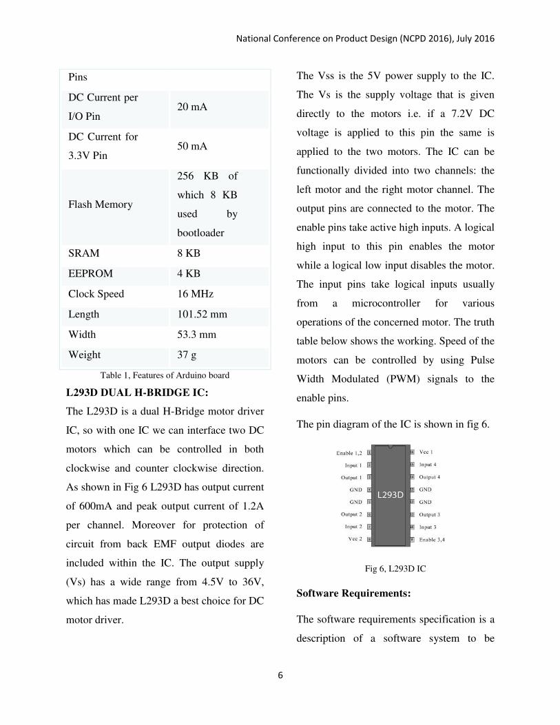
Table 1, briefs the summary of this
microcontroller board
Microcontroller ATmega2560
Operating
Voltage 5V
Input Voltage
(recommended) 7-12V
Input Voltage
(limit) 6-20V
Digital I/O
Pins
54 (of which
15 provide
PWM
output)
Analog Input 16
National Conference on Product Design (NCPD 2016), July 2016
6
Pins
DC Current per
I/O Pin 20 mA
DC Current for
3.3V Pin 50 mA
Flash Memory
256 KB of
which 8 KB
used by
bootloader
SRAM 8 KB
EEPROM 4 KB
Clock Speed 16 MHz
Length 101.52 mm
Width 53.3 mm
Weight 37 g
Table 1, Features of Arduino board
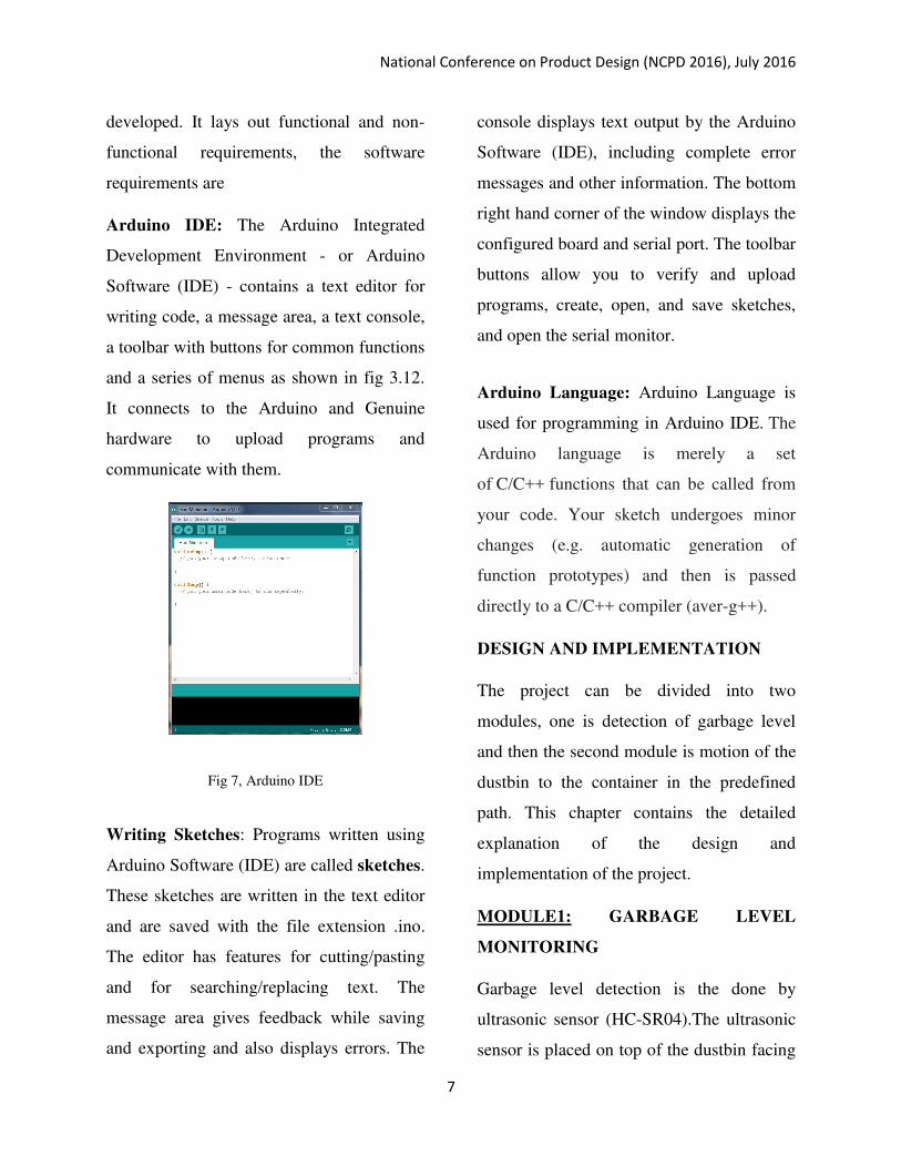
L293D DUAL H-BRIDGE IC:
The L293D is a dual H-Bridge motor driver
IC, so with one IC we can interface two DC
motors which can be controlled in both
clockwise and counter clockwise direction.
As shown in Fig 6 L293D has output current
of 600mA and peak output current of 1.2A
per channel. Moreover for protection of
circuit from back EMF output diodes are
included within the IC. The output supply
(Vs) has a wide range from 4.5V to 36V,
which has made L293D a best choice for DC
motor driver.
The Vss is the 5V power supply to the IC.
The Vs is the supply voltage that is given
directly to the motors i.e. if a 7.2V DC
voltage is applied to this pin the same is
applied to the two motors. The IC can be
functionally divided into two channels: the
left motor and the right motor channel. The
output pins are connected to the motor. The
enable pins take active high inputs. A logical
high input to this pin enables the motor
while a logical low input disables the motor.
The input pins take logical inputs usually
from a microcontroller for various
operations of the concerned motor. The truth
table below shows the working. Speed of the
motors can be controlled by using Pulse
Width Modulated (PWM) signals to the
enable pins.
The pin diagram of the IC is shown in fig 6.
Fig 6, L293D IC
Software Requirements:
The software requirements specification is a
description of a software system to be
National Conference on Product Design (NCPD 2016), July 2016
7
developed. It lays out functional and non-
functional requirements, the software
requirements are
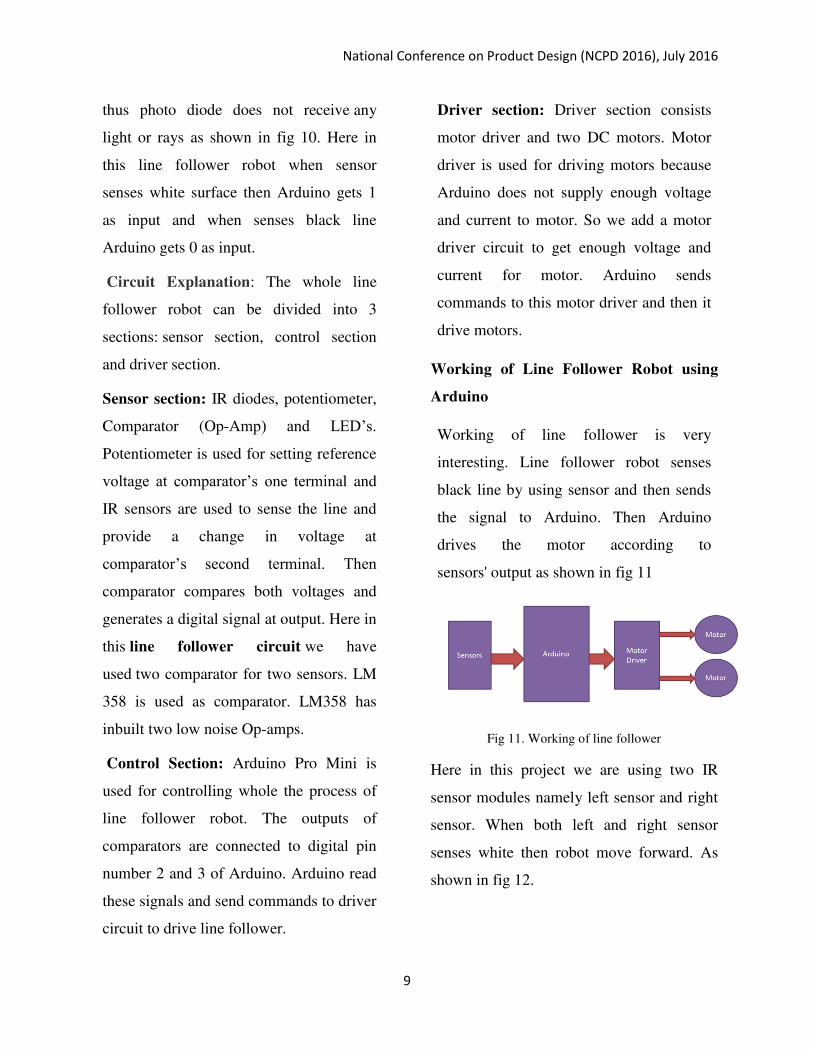
Arduino IDE: The Arduino Integrated
Development Environment - or Arduino
Software (IDE) - contains a text editor for
writing code, a message area, a text console,
a toolbar with buttons for common functions
and a series of menus as shown in fig 3.12.
It connects to the Arduino and Genuine
hardware to upload programs and
communicate with them.
Fig 7, Arduino IDE
Writing Sketches: Programs written using
Arduino Software (IDE) are called sketches.
These sketches are written in the text editor
and are saved with the file extension .ino.
The editor has features for cutting/pasting
and for searching/replacing text. The
message area gives feedback while saving
and exporting and also displays errors. The
console displays text output by the Arduino
Software (IDE), including complete error
messages and other information. The bottom
right hand corner of the window displays the
configured board and serial port. The toolbar
buttons allow you to verify and upload
programs, create, open, and save sketches,
and open the serial monitor.
Arduino Language: Arduino Language is
used for programming in Arduino IDE. The
Arduino language is merely a set
of C/C++ functions that can be called from
your code. Your sketch undergoes minor
changes (e.g. automatic generation of
function prototypes) and then is passed
directly to a C/C++ compiler (aver-g++).
DESIGN AND IMPLEMENTATION
The project can be divided into two
modules, one is detection of garbage level
and then the second module is motion of the
dustbin to the container in the predefined
path. This chapter contains the detailed
explanation of the design and
implementation of the project.
MODULE1: GARBAGE LEVEL
MONITORING
Garbage level detection is the done by
ultrasonic sensor (HC-SR04).The ultrasonic
sensor is placed on top of the dustbin facing

National Conference on Product Design (NCPD 2016), July 2016
8
the bottom. The sensor continuously emits
the sonic waves, when the sonic waves hit
the object and reflect back, the echo in the
sensor senses the waves and calculates the
distance of the object as shown in Fig 8.
Fig 8, Connection of ultrasonic sensor with Arduino
board
MODULE2: MOTION OF DUSTBIN
TOWARDS THE CONTAINER
LINE Follower robot using IR sensor:
Line follower Robot is a machine which
follows a line, either a black line or white
line. Basically there are two types of line
follower robots: one is black line follower
which follows black line and second is
white line follower which follows white
line. Line follower actually senses the line
and run over it.
Concepts of Line Follower: Concept of
working of line follower is related to light.
We use here the behaviour of light at black
and white surface. When light fall on a white
surface it is almost full reflected and in case
of black surface light is completely
absorbed. This behaviour of light is used
in building a line follower robot.
Fig 9, IR sensor on white surface
Fig 10, IR sensor on black surface
In Arduino based line follower robot we
have used IR Transmitters and IR
receivers also called photo diodes. They
are used for sending and receiving light.
IR transmits infrared lights. When infrared
rays falls on white surface, it’s reflected
back and cached by photodiodes which
generates some voltage changes as shown
in fig 9. When IR light falls on a black
surface, light is absorb by the black
surface and no rays are reflected back,
National Conference on Product Design (NCPD 2016), July 2016
9
thus photo diode does not receive any
light or rays as shown in fig 10. Here in
this line follower robot when sensor
senses white surface then Arduino gets 1
as input and when senses black line
Arduino gets 0 as input.
Circuit Explanation: The whole line
follower robot can be divided into 3
sections: sensor section, control section
and driver section.
Sensor section: IR diodes, potentiometer,
Comparator (Op-Amp) and LED’s.
Potentiometer is used for setting reference
voltage at comparator’s one terminal and
IR sensors are used to sense the line and
provide a change in voltage at
comparator’s second terminal. Then
comparator compares both voltages and
generates a digital signal at output. Here in
this line follower circuit we have
used two comparator for two sensors. LM
358 is used as comparator. LM358 has
inbuilt two low noise Op-amps.
Control Section: Arduino Pro Mini is
used for controlling whole the process of
line follower robot. The outputs of
comparators are connected to digital pin
number 2 and 3 of Arduino. Arduino read
these signals and send commands to driver
circuit to drive line follower.
Driver section: Driver section consists
motor driver and two DC motors. Motor
driver is used for driving motors because
Arduino does not supply enough voltage
and current to motor. So we add a motor
driver circuit to get enough voltage and
current for motor. Arduino sends
commands to this motor driver and then it
drive motors.
Working of Line Follower Robot using
Arduino
Working of line follower is very
interesting. Line follower robot senses
black line by using sensor and then sends
the signal to Arduino. Then Arduino
drives the motor according to
sensors' output as shown in fig 11
Fig 11. Working of line follower
Here in this project we are using two IR
sensor modules namely left sensor and right
sensor. When both left and right sensor
senses white then robot move forward. As
shown in fig 12.
National Conference on Product Design (NCPD 2016), July 2016
10
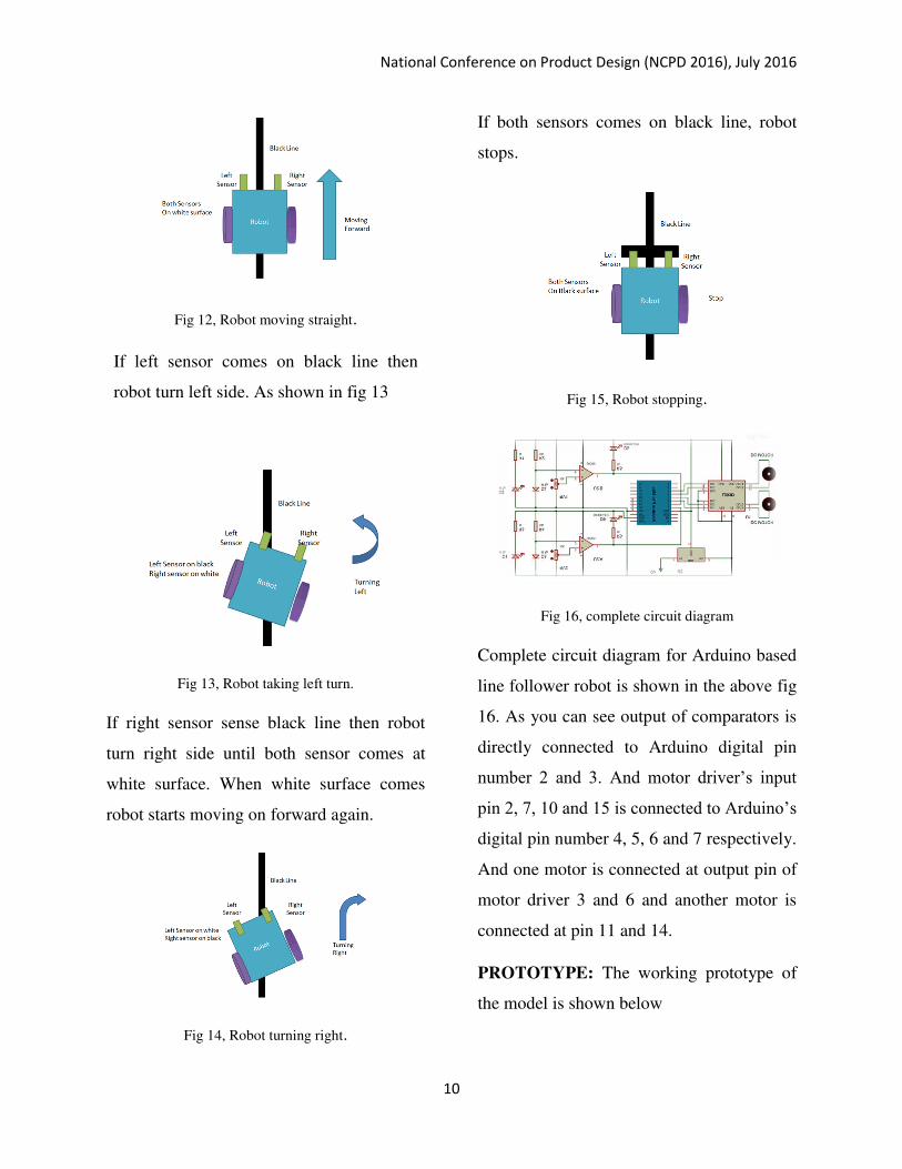
Fig 12, Robot moving straight.
If left sensor comes on black line then
robot turn left side. As shown in fig 13
Fig 13, Robot taking left turn.
If right sensor sense black line then robot
turn right side until both sensor comes at
white surface. When white surface comes
robot starts moving on forward again.
Fig 14, Robot turning right.
If both sensors comes on black line, robot
stops.
Fig 15, Robot stopping.
Fig 16, complete circuit diagram
Complete circuit diagram for Arduino based
line follower robot is shown in the above fig
16. As you can see output of comparators is
directly connected to Arduino digital pin
number 2 and 3. And motor driver’s input
pin 2, 7, 10 and 15 is connected to Arduino’s
digital pin number 4, 5, 6 and 7 respectively.
And one motor is connected at output pin of
motor driver 3 and 6 and another motor is
connected at pin 11 and 14.
PROTOTYPE: The working prototype of
the model is shown below
National Conference on Product Design (NCPD 2016), July 2016
11
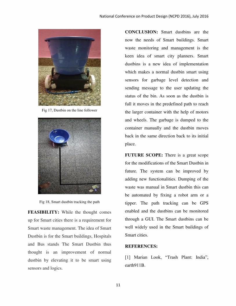
Fig 17, Dustbin on the line follower
Fig 18, Smart dustbin tracking the path
FEASIBILITY: While the thought comes
up for Smart cities there is a requirement for
Smart waste management. The idea of Smart
Dustbin is for the Smart buildings, Hospitals
and Bus stands The Smart Dustbin thus
thought is an improvement of normal
dustbin by elevating it to be smart using
sensors and logics.
CONCLUSION: Smart dustbins are the
now the needs of Smart buildings. Smart
waste monitoring and management is the
keen idea of smart city planners. Smart
dustbins is a new idea of implementation
which makes a normal dustbin smart using
sensors for garbage level detection and
sending message to the user updating the
status of the bin. As soon as the dustbin is
full it moves in the predefined path to reach
the larger container with the help of motors
and wheels. The garbage is dumped to the
container manually and the dustbin moves
back in the same direction back to its initial
place.
FUTURE SCOPE: There is a great scope
for the modifications of the Smart Dustbin in
future. The system can be improved by
adding new functionalities. Dumping of the
waste was manual in Smart dustbin this can
be automated by fixing a robot arm or a
tipper. The path tracking can be GPS
enabled and the dustbins can be monitored
through a GUI. The Smart dustbins can be
well widely used in the Smart buildings of
Smart cities.
REFERENCES:
[1] Marian Look, “Trash Plant: India”,
earth911B.

National Conference on Product Design (NCPD 2016), July 2016
12
[2]Basic Feature, “Solid waste Management
Project by MCGM”.
[3] Microtronics Technologies, “GSM based
garbage and waste collection bins overflow
indicator”, September 2013.
[4] “Smart garbage management system” International Journal of Engineering
Research &Technology (IJERT) ISSN:
2278-
0181.www.ijert.orgIJERTV4IS031175Vol.
4 Issue 03, March-2015