grid code - blpc.com.bb · the grid code, unless in consequence of negligence of the blpc....
TRANSCRIPT

GRID CODE
Interconnection Requirements At Voltages 24.9 kV and below
Prepared by The Barbados Light & Power Company Limited with the assistance of Energynautics GmbH
March 2017

The Barbados Light & Power Company Limited. Grid Code: INTERCONNECTION REQUIREMENTS AT VOLTAGES 24.9 kV AND BELOW
2
Guidance to Document Structure The Barbados Grid Code is split into different sections depending on the size of the generators. For generating facilities with capacity at or less than 150 kW, only the following Sections are relevant:
Section 1 (General Conditions)
Section 0 (Planning Code for Generators ≤ 150 kW)
Section 4 (Connection Code for Generators ≤ 150 kW)
Section 6 (Operating Code for Generators ≤ 150 kW)
Section 8 (Appendix for Generators ≤ 150 kW)
Section 9 (Information on BLPC’s Transmission and Distribution System)
Section 10.1 and the APC-S Form in Section 11 For generating facilities with capacity more than 150 kW, only the following Sections are relevant:
Section 1 (General Conditions)
Section 3 (Planning Code for Generators > 150 kW)
Section 5 (Connection Code for Generators > 150 kW)
Section 7 (Operating Code for Generators > 150 kW)
Section 9 (Information on BLPC’s Transmission and Distribution System)
Section 10.2 and the APC-L Form in Section 11

The Barbados Light & Power Company Limited. Grid Code: INTERCONNECTION REQUIREMENTS AT VOLTAGES 24.9 kV AND BELOW
3
TABLE OF CONTENTS
1. General Conditions ................................................................................ 11
1.1 Introduction .............................................................................................. 11 1.2 Scope ....................................................................................................... 12 1.3 Objectives ................................................................................................ 13 1.4 Document Structure ................................................................................. 14 1.5 Responsibilities ........................................................................................ 14
1.6 Terminology ............................................................................................. 15
1.7 Capacity Limitations on Generator Interconnections ............................... 16
1.7.1 Three Phase Generators ............................................................. 16 1.7.2 Single Phase Generators ............................................................ 17
1.8 Document Reproduction .......................................................................... 17 1.8.1 Document Credit ......................................................................... 18
1.9 Terms and Definitions .............................................................................. 18
2. Planning Code for Generators ≤ 150 kW .............................................. 25
2.1 Introduction .............................................................................................. 25 2.2 Objectives ................................................................................................ 25 2.3 Scope ....................................................................................................... 26
2.4 Overview of Connection Application Process .......................................... 26 2.5 Application for Proposed Connection ....................................................... 27
2.6 Application Review ................................................................................... 27 2.7 Further Documents Required for Connection .......................................... 28
2.8 Interconnection ........................................................................................ 28 2.9 Data for System Planning ........................................................................ 28
2.10 Validation and Verification of Data ........................................................... 28
3. Planning Code for Generators > 150 kW .............................................. 30
3.1 Introduction .............................................................................................. 30 3.2 Objectives ................................................................................................ 30 3.3 Scope ....................................................................................................... 31 3.4 Overview of Connection Application Process .......................................... 31 3.5 Application for Proposed Connection ....................................................... 32
3.6 Connection Impact Assessment ............................................................... 32
3.7 Grid Connection Offer .............................................................................. 33
3.8 Power Purchase Agreement .................................................................... 33 3.9 Further Documents Required for Connection .......................................... 34 3.10 Interconnection ........................................................................................ 34 3.11 Data for System Planning ........................................................................ 34 3.12 Validation and Verification of Data ........................................................... 35
4. Connection Code for Generators ≤ 150 kW ......................................... 36 4.1 Introduction .............................................................................................. 36
The Barbados Light & Power Company Limited. Grid Code: INTERCONNECTION REQUIREMENTS AT VOLTAGES 24.9 kV AND BELOW
4
4.2 General Requirements ............................................................................. 36 4.2.1 Point of Delivery – Responsibilities ............................................. 36 4.2.2 Point of Disconnection – Safety .................................................. 36 4.2.3 Interconnection Grounding .......................................................... 36
4.2.4 Phasing ....................................................................................... 37 4.2.5 Device Rating .............................................................................. 37
4.3 Performance Requirements ..................................................................... 37 4.3.1 Voltage Flicker ............................................................................ 37 4.3.2 Harmonic Distortion ..................................................................... 37
4.3.3 Voltage Imbalance....................................................................... 38 4.3.4 DC Injection ................................................................................. 38
4.3.5 Voltage Rise ................................................................................ 38 4.3.6 Reactive Power Capability .......................................................... 38 4.3.7 Under-Voltage and Over-Voltage Ride Through ......................... 39 4.3.8 Under Frequency and Over Frequency Ride Through ................ 41
4.3.9 Frequency Droop for Synchronous Generators ........................... 43 4.3.10 Over-Frequency Active Power Reduction for Non-Synchronous
Generators .................................................................................. 43 4.4 Protection Requirements ......................................................................... 44
4.4.1 Interconnection Protection Function Requirements ..................... 44
4.4.2 Over-Current Protection .............................................................. 44 4.4.3 Under-Voltage and Over-Voltage Protection ............................... 44
4.4.4 Under Frequency and Over Frequency Protection ...................... 45
4.4.5 Short-Time Contingency .............................................................. 46
4.4.6 Reconnection After Protection Tripping ....................................... 46 4.4.7 Anti-Islanding .............................................................................. 47
4.4.8 Interrupting Device Ratings ......................................................... 47 4.5 Operating Requirements .......................................................................... 47
4.5.1 Synchronization ........................................................................... 47
4.5.2 Grid-Tied Inverters ...................................................................... 47 4.6 Metering Requirements ............................................................................ 47
4.6.1 Metering for SDG ........................................................................ 48 4.6.2 Metering for SDG With Battery Storage ...................................... 52
4.6.3 Metering for SDG With Interconnection Transformer .................. 55 4.6.4 Labelling ...................................................................................... 55
4.7 Verification and Certification Requirements ............................................. 55
5. Connection Code for Generators > 150 kW ......................................... 56 5.1 Introduction .............................................................................................. 56 5.2 General Requirements ............................................................................. 56
5.2.1 Safety .......................................................................................... 56
5.2.2 Active Power ............................................................................... 56 5.2.3 Reactive Power ........................................................................... 57 5.2.4 Equipment Rating and Requirements.......................................... 57
5.2.5 Point of Common Coupling (PCC) .............................................. 58

The Barbados Light & Power Company Limited. Grid Code: INTERCONNECTION REQUIREMENTS AT VOLTAGES 24.9 kV AND BELOW
5
5.2.6 New Line ..................................................................................... 58 5.2.7 Isolation Device ........................................................................... 59 5.2.8 Interrupting Device Rating ........................................................... 60 5.2.9 Phasing ....................................................................................... 61
5.2.10 Temporary Over-Voltage (TOV) .................................................. 61 5.2.11 Grounding ................................................................................... 61 5.2.12 Interconnection Transformer Configuration ................................. 63 5.2.13 LDG Interconnection to BLPC’s Transmission and Distribution
System ........................................................................................ 64
5.2.14 High Voltage Interrupting Device (HVI) ....................................... 66 5.2.15 Station Service for Essential Loads ............................................. 67
5.2.16 Batteries/DC Supply .................................................................... 67 5.2.17 Fault Levels ................................................................................. 68 5.2.18 Insulation Coordination ................................................................ 69 5.2.19 Instrument Transformers for Use in Protection Systems ............. 69
5.2.20 Power Quality Monitoring Device ................................................ 69 5.2.21 Protection from Electromagnetic Interference (EMI).................... 70
5.2.22 Surge Withstand .......................................................................... 70 5.2.23 Simulation Models ....................................................................... 71 5.2.24 Generators Paralleling for 5 Cycles or Less (Closed Transition
Switching) .................................................................................... 71 5.2.25 Provision for Future Changes ...................................................... 72
5.3 Performance Requirements ..................................................................... 73
5.3.1 General ....................................................................................... 73
5.3.2 Power Quality .............................................................................. 73 5.3.3 Reactive Power and Voltage Control........................................... 78
5.3.4 Disturbances ............................................................................... 79 5.3.5 Resonance Analysis .................................................................... 80 5.3.6 Self-Excitation Analysis ............................................................... 80
5.3.7 Under-Voltage and Over-Voltage Ride Through ......................... 80 5.3.8 Under-Frequency and Over-Frequency Ride Through ................ 83 5.3.9 Frequency Droop for Synchronous Generators ........................... 84 5.3.10 Over-Frequency Active Power Reduction for Non-Synchronous
Generators .................................................................................. 85 5.4 Protection Requirements ......................................................................... 86
5.4.1 General Requirements ................................................................ 86
5.4.2 Sensitivity and Coordination ........................................................ 87 5.4.3 Protection Operating Times ......................................................... 87 5.4.4 Breaker Fail (BF) ......................................................................... 87 5.4.5 Three-Phase Generators ............................................................. 89
5.4.6 Phase and Ground Fault Protection ............................................ 96 5.4.7 Open Phase Protection ............................................................... 97 5.4.8 Feeder Relay Directioning (for ldgs of class 2 and above) .......... 97
5.4.9 Over Frequency/Under Frequency Protection ............................. 97
The Barbados Light & Power Company Limited. Grid Code: INTERCONNECTION REQUIREMENTS AT VOLTAGES 24.9 kV AND BELOW
6
5.4.10 Overvoltage/Undervoltage Protection.......................................... 98 5.4.11 Short-Time Contingency .............................................................. 99 5.4.12 Reconnection after Protection Tripping (For class 2 and above
unless otherwise stated) ............................................................ 100
5.4.13 Anti-Islanding Protection (For class 2 and above unless otherwise stated) ....................................................................................... 101
5.4.14 Transfer Trip (TT) (LDG of Class 2 and above) ......................... 102 5.4.15 Distributed Generator End Open (DGEO) (LDG of Class 2 and
above) ....................................................................................... 103
5.4.16 Low Set Block Signal (LSBS) (LDG of Class 2 and above) ....... 104 5.4.17 DGEO And LSBS Design (LDG of Class 2 and above) ........... 104
5.4.18 Special Interconnection Protection (LDG of Class 2 and above) 104
5.4.19 Protection Scheme Failures (LDG of Class 2 and above) ......... 105 5.4.20 Interconnection Protection Acceptance ..................................... 106
5.4.21 Protection Changes ................................................................... 107 5.5 Operating Requirements ........................................................................ 107
5.5.1 General ..................................................................................... 107 5.5.2 Islanding .................................................................................... 108 5.5.3 Unintentional Energization ........................................................ 109
5.5.4 Synchronization ......................................................................... 109 5.5.5 Single Connection Path ............................................................. 110
5.5.6 Automatic Disconnection of Generation and HV Ground Sources .................................................................................................. 111
5.6 Control and Monitoring Requirements ................................................... 111 5.6.1 General ..................................................................................... 112
5.6.2 Control Facilities ........................................................................ 112 5.6.3 Operating Data, Telemetry and Monitoring ............................... 113
5.7 Telecommunications Requirements ....................................................... 115
5.7.1 General ..................................................................................... 115 5.7.2 Telecommunications Facilities for Teleprotection ...................... 116 5.7.3 Telecommunications Facilities for Real-Time Control and
Monitoring ................................................................................. 116
5.7.4 Reliability Requirements ............................................................ 117 5.8 Metering Requirements .......................................................................... 118 5.9 Commissioning and Verification Requirements ..................................... 118
5.9.1 BLPC Cover Process ................................................................ 119 5.9.2 Commissioning and Verification Generic Requirements ........... 119 5.9.3 Documentation of Test Results ................................................. 121
6. Operating Code for Generators ≤ 150 kW .......................................... 122
6.1 Introduction ............................................................................................ 122 6.2 Objectives .............................................................................................. 122 6.3 Scope ..................................................................................................... 122
6.4 Power System Restoration .................................................................... 122
The Barbados Light & Power Company Limited. Grid Code: INTERCONNECTION REQUIREMENTS AT VOLTAGES 24.9 kV AND BELOW
7
6.5 Safety Coordination ............................................................................... 123
7. Operating Code for Generators > 150 kW .......................................... 124 7.1 Introduction ............................................................................................ 124 7.2 Objectives .............................................................................................. 124
7.3 Scope ..................................................................................................... 124 7.4 Scheduled Outages (LDGs of class 2 & above) ..................................... 124 7.5 Operation Scheduling and Dispatch ....................................................... 125 7.6 Submission of Monthly Availability Data ................................................ 125 7.7 Submission of Hourly Availability Data ................................................... 126
7.8 Fault & Other Event Reporting Requirements ........................................ 126
7.8.1 General (LDG of CLass 2 and above) ....................................... 126
7.8.2 Power Quality Recording (LDG of CLass 2 and above) ............ 128 7.8.3 Disturbance Fault Recording ..................................................... 128 7.8.4 Sequence of Event Recording ................................................... 129
7.9 Operating Reserves (LDG of CLass 2 and above)................................. 130
7.10 Power System Restoration .................................................................... 131 7.11 Operational Testing ................................................................................ 131
7.12 Safety Coordination ............................................................................... 132
8. Appendix for Generators ≤ 150 kW .................................................... 133 8.1 Sample Electrical One-Line Diagram ..................................................... 133
8.2 Sample of Utility Warning Sign of Distributed Generation ...................... 134 8.3 Sample of Safety Disconnect Switch ..................................................... 135
8.4 Configurations ........................................................................................ 136
8.5 SDG Interconnection Site Inspection ..................................................... 140
9. Appendix A – BLPC Characteristics (Informative) ............................ 141 9.1 General Characteristics ......................................................................... 141
9.2 System Frequency ................................................................................. 141 9.3 Voltage ................................................................................................... 141
9.4 Voltage Regulation ................................................................................. 142 9.5 Voltage and Current Unbalance ............................................................. 143 9.6 Power Quality......................................................................................... 143 9.7 Fault Levels............................................................................................ 143 9.8 System Grounding ................................................................................. 144
9.9 BLPC Distribution System Feeder Protection ........................................ 144 9.10 Automatic Reclosing (Fault Clearing) ..................................................... 144
9.11 Phasing .................................................................................................. 145 9.12 Multiple Source (Networked) System ..................................................... 145 9.13 Frequency of Interruption ....................................................................... 145 9.14 Abnormal Conditions .............................................................................. 146 9.15 Feeder Disconnection ............................................................................ 146
10. Appendix B – Planning Code Flow Charts (Informative) .................. 147 10.1 Connection Procedure for SDG ............................................................. 147

The Barbados Light & Power Company Limited. Grid Code: INTERCONNECTION REQUIREMENTS AT VOLTAGES 24.9 kV AND BELOW
8
10.2 Connection Procedure for LDG .............................................................. 148
11. Appendix C – Forms: Application for Proposed Connection (APC) 149

The Barbados Light & Power Company Limited. Grid Code: INTERCONNECTION REQUIREMENTS AT VOLTAGES 24.9 kV AND BELOW
9
LIMITATION OF LIABILITY AND DISCLAIMER
BLPC “Grid Code: Interconnections Requirements at Voltages 24.9 kV and below” (the “Grid Code”) identifies minimum requirements for generation projects connecting to the BLPC’s distribution system. Additional requirements may need to be met by the owner of the generation project to ensure that the final connection design meets all local and national standards and codes and is safe for the application intended. The Grid Code is based on a number of assumptions, only some of which have been identified. Changing system conditions, standards and equipment may make those assumptions invalid. In no way shall BLPC, its affiliates, parent company, directors, officers, or employees be liable for any loss or damage arising from the use of the Grid Code, any conclusions a user derives from the Grid Code or any reliance by the user on the Grid Code, unless in consequence of negligence of the BLPC. Reference to the Grid Code, or the use of the Grid Code, in any specific project or project document should be for information and shall not constitute endorsement or recommendation or favoring by BLPC, its parent company, its affiliates, directors, officers, or employees. BLPC reserves the right to amend the Grid Code at any time subject to part 5 Section 31 of the ELPA. Any person wishing to make a decision based on the content of the Grid Code should consult with BLPC prior to making any such decision. The specific quantities outlined in sections of the Grid Code relating to the amps and watts etc. are based on the BLPC’s engineer’s judgment regarding the system performance viability considering varying generation scenarios and locations along the Transmission and Distribution system. As such, the specific quantities shall only be used as a guide, subject to in-depth evaluation, in the Connection Impact Assessment (CIA) process.
The Barbados Light & Power Company Limited. Grid Code: INTERCONNECTION REQUIREMENTS AT VOLTAGES 24.9 kV AND BELOW
10
CONTACT/PUBLISHER
Please forward questions/comments regarding the Grid Code to the following email address: EMAIL: [email protected] REVISION HISTORY
REVISION HISTORY
DATE
VERSION COMMENTS
March 2017 Rev. 3 Revision after consultations with the Government Electrical Engineering Department
January 2016 Rev. 2 Revision by Energynautics GmbH following Barbados Intermittent Penetration Study. Incorporation of technical requirements for generators ≤ 150 kW. New Planning Code and Operating Code.
May 2014 Rev. 1 Revisions following Public Consultation and internal review. Revisions include updating of the Limitation of Liability and Disclaimer and updating/removal of some Terms and Definitions and updating References. Pages affected 5, 9, 15, 18, 19, 23, 49, 57, 72, 85, 86, 87
April 2013 Rev. 0 First Issue

The Barbados Light & Power Company Limited. Grid Code: INTERCONNECTION REQUIREMENTS AT VOLTAGES 24.9 kV AND BELOW
11
1. GENERAL CONDITIONS
1.1 INTRODUCTION
This document, ― “Grid Code: Interconnection Requirements at Voltages 24.9 kV and below” (the “Grid Code”) - outlines the technical, planning and operational requirements for the installation, or modification, of Distributed Generation (DG) projects connecting to the Barbados Light & Power Company Limited’s (BLPC) Transmission and Distribution System feeders at ≤ 24.9 kV. Connection of DG supply sources to the BLPC’s Transmission and Distribution System feeders1 impacts the steady-state and transient voltage profiles and current distribution along the feeder in response to changing supply, load and fault conditions. These connections must:
1. Preserve acceptable safe operation of the Distribution System for the general public, customers and employees that work on the Transmission and Distribution System.
2. Maintain reliability and quality of service to BLPC customers. 3. Abide by the requirements of the Government Electrical Engineering
Department (GEED), BLPC Safety procedures, BLPC Information and Requirements booklet, the National Fire Protection Association (NFPA) 70, National Electric Code (NEC) standards, and other standards stated below.
4. Be compatible with BLPC’s standard operating, protection, control and metering systems and practices.
To accomplish this, the design of the power equipment, protection, control and metering systems used at the DG Facility interconnection must meet specific minimum requirements. Depending on the capacity and electrical characteristics of the connecting DG Facility, specific additions and/or modifications may be required to BLPC’s equipment, protection, control and metering systems to facilitate the connection. This document has been developed with reference to the requirements of the Institute of Electrical and Electronics Engineers (IEEE) Standard 1547 – Interconnecting Distributed Resources with Electric Power Systems, CAN/CSA C22.3 No. 9-08 Standard – Interconnection of Distributed Resources and Electricity Supply Systems, British Standard EN 50160, the German guidelines from BDEW for Medium Voltage (2008) and from VDE for Low Voltage (VDE AR-N 4105:2011-08), the NFPA NEC 2011 Code and the BLPC Switching and Tagging Procedures.
1 See section 1.9 “Terms and Definitions” for definitions of Transmission System and Distribution System.

The Barbados Light & Power Company Limited. Grid Code: INTERCONNECTION REQUIREMENTS AT VOLTAGES 24.9 kV AND BELOW
12
It is imperative that these requirements are understood by those delegated or contracted by the DG Owner for the planning, design, equipment manufacture and supply, construction, commissioning, operation and maintenance of the DG Facility.
1.2 SCOPE
This document applies to all single-phase or three-phase DG facilities that seek to connect to BLPC’s Transmission and Distribution System at ≤ 24.9 kV, regardless of size. Existing generator facilities with existing connections only need to comply with this document starting from the time when substantial modifications to the generator facility or its connection are made. This document is intended to be applied to electric power generators using all types of energy sources, energy storage and energy conversion technologies – directly connected synchronous and asynchronous rotating machines, and those connecting via inverters or static power converters which connect at or below the threshold mentioned above. This document does not apply to generators paralleling with BLPC for less than 100ms (Momentary Closed Transition Switching) except as noted in Section 5.2.24. The Connection Code in Section 4 (for generators ≤ 150 kW) and Section 5 (for generators > 150 kW) contains minimum technical requirements that the DG Owner is required to comply with in order to connect to BLPC’s Transmission or Distribution System. Depending on the size of the interconnecting DG Facility, the voltage of the interconnected distribution feeder, and whether the facility is single-phase or three-phase certain requirements may not apply. It is the DG Owner‘s responsibility to ensure that requirements are met for the specific system configuration. These requirements have been developed to ensure that the integrity and power quality of BLPC’s Transmission and Distribution System are maintained to acceptable levels after connection of the DG Facility. Additional requirements may be necessary to address unique situations and the DG Owner shall be advised of any such requirements at the appropriate stage by BLPC. Any exemptions require written approval from BLPC. This document does not specify all of the protection requirements for the generator and equipment at the DG Facility. Minimum protection requirements for interconnection are, however, specified in Section 4.4 (for generators ≤ 150 kW) and Section 5.4 (for generators > 150 kW). The DG Owner should ensure that adequate generator protections as well as protections for other equipment within the DG Facility are installed. This is to protect them from damage from faults or abnormal conditions which may originate at the DG Facility or from BLPC Transmission and/or Distribution System. This document does not constitute a design handbook and is not a substitute for any Safety Code. DG Owners who are considering the development of a DG facility
The Barbados Light & Power Company Limited. Grid Code: INTERCONNECTION REQUIREMENTS AT VOLTAGES 24.9 kV AND BELOW
13
to connect to BLPC’s system, shall engage the services of a professional engineer or a registered consulting firm qualified to provide design and consulting services for electrical interconnection facilities in Barbados.
1.3 OBJECTIVES
BLPC is committed to establishing the rules for connection of approved forms of generation to the Transmission and Distribution System, while preserving a safe and reliable electrical supply to all of its customers. Interconnection of the DG Facilities must conform to relevant regulations in Barbados and international design standards. The following objectives shall be integrated into the design specification, construction, operation and maintenance of the DG Facility interconnection. SAFETY - The DG interconnection must not create a safety hazard to the general public, BLPC customers, BLPC employees who work on the Transmission and Distribution System or to personnel working in the DG Facility. POWER QUALITY - Connection of DG Facilities must not materially degrade the power quality of the BLPC Transmission and Distribution System below acceptable levels. RELIABILITY - Connection of DG Facilities must not compromise the reliability of the BLPC Transmission and Distribution System. ACHIEVABILITY - The DG Facility interconnection requirements will allow fair and equitable access for all DG Owners. OPERABILITY - The DG Facility connection must not restrict the operation of the BLPC Transmission and Distribution System. All aspects of the interconnection that can impact the BLPC Transmission and Distribution System must be compatible with BLPC standard operating, protection, control and metering systems and practices.
The Barbados Light & Power Company Limited. Grid Code: INTERCONNECTION REQUIREMENTS AT VOLTAGES 24.9 kV AND BELOW
14
1.4 DOCUMENT STRUCTURE
The Barbados Grid Code is split into three major sections:
1. The Planning Code (PC), which describes the planning requirements and application procedures for generators connecting to BLPC’s network.
2. The Connection Code (CC), which describes the technical requirements for generators connecting to BLPC’s Transmission and Distribution System.
3. The Operating Code (OC), which describes the operational requirements and procedures of BLPC.
Each major section is divided into two parts according to the size of the power-generating facility. The first part is for generating facilities with an aggregate capacity at or less than 150 kW, referred to in this document as Small Distributed Generators (SDG). The second part is for generating facilities with an aggregate capacity of greater than 150 kW, referred to in this document as Large Distributed Generators (LDG).
1.5 RESPONSIBILITIES
Connecting to BLPC's Distribution systems involves several steps and both BLPC and the DG Owner have distinct responsibilities. BLPC is responsible for:
1. The safety, reliability, power quality and operation of BLPC’s Transmission and Distribution System and ensuring the DG Facility connection does not adversely affect the network or BLPC’s existing customers.
2. Maintaining the integrity of BLPC’s Transmission and Distribution System.
3. Operating its own systems in compliance with all applicable regulatory codes in Barbados and international standards.
4. Establishing the terms and conditions for Operating and Technical Requirements consistent with the DG Facility connection “Objectives”.
5. Providing metering for DG facilities.

The Barbados Light & Power Company Limited. Grid Code: INTERCONNECTION REQUIREMENTS AT VOLTAGES 24.9 kV AND BELOW
15
DG Owners are responsible for:
1. The safety, design, construction, operation, protection and control, and maintenance of the DG Facility.
2. Operating the DG facility in compliance with all applicable regulatory codes in Barbados and within the guidelines of all applicable GEED codes and international standards.
3. Ensuring that the DG Facility is compatible with BLPC’s standard operating, protection, control and metering systems and practices.
4. Abiding by the terms and conditions of BLPC’s Operating and Technical Requirements.
1.6 TERMINOLOGY
In this Document, “Grid Code”, the term:
1. “Shall” is used to express a requirement – i.e. a provision that the DG Owner is obligated to satisfy in order to comply with the requirements of this document.
2. “Should” is used to express a recommendation or that which is advised but not required.
3. “May” is used to express an option or that which is permissible within the limits of this document.
Requirements may follow with a “Background Information” and “Design Considerations" section below them which do not include requirements. The purpose of these sections is to provide informative material, rationale on which the requirements in the section are based on and some design considerations. These sections are included as required and are not necessarily present for all requirements.

The Barbados Light & Power Company Limited. Grid Code: INTERCONNECTION REQUIREMENTS AT VOLTAGES 24.9 kV AND BELOW
16
1.7 CAPACITY LIMITATIONS ON GENERATOR
INTERCONNECTIONS
Feeder Loading Limits
The capacity for all sections of all feeders, the “feeder limitation,” is based mainly on the distance from the BLPC’s substation to the DG‘s Point of Common Coupling (PCC). The feeder limitation applies to all DGs connected, or connecting, to the feeder and considers the rated output capacity of each DG. Any single DG connection can affect the capacity available for all sections of the feeder. For all sections of the feeder, the total current shall not exceed:
a) 250 Amps for BLPC feeders operating at 11 kV with conductor size 1/0 AWG.AL and 400 amps for feeders with conductor size of 336 mcm.
b) 700 Amps for each BLPC feeder operating at 24.9 kV with conductor size of 795 mcm and 400 amps for feeders with conductor size of 336 mcm.
ACCEPTABLE GENERATION LIMIT AT A TRANSMISSION SUBSTATION (TS) OR A DISTRIBUTION SUBSTATION (DS) The acceptable generation limit at a TS or a DS will be determined on a case by case basis, in conjunction with the location of the TS or DS and the connected feeders. SHORT CIRCUIT (SC) LIMITS The SC limits at the TS low voltage bus, or at any portion of distribution feeder, shall not be exceeded by the addition of DG Facilities. The impact on SC limits will be assessed in the CIA. Refer to Section 5.2.17 for requirements.
1.7.1 THREE PHASE GENERATORS
1. The individual generation limits for three-phase DG Facilities
interconnecting to the BLPC Transmission and Distribution System feeders are:

The Barbados Light & Power Company Limited. Grid Code: INTERCONNECTION REQUIREMENTS AT VOLTAGES 24.9 kV AND BELOW
17
a) 1.5 MW per connection on feeders operating at 11 kV; and
b) up to a maximum of 25 MW on a 24.9 kV feeder or transmission line.
2. The feeder limitation determines the total acceptable three-phase generation allowed for all sections of BLPC’s Transmission and Distribution System feeders. These limits are:
a) 5 MW for feeders operating at 11 kV
b) 25 MW for feeders operating at 24.9 kV
These limitations are a general rule and may be modified based on the Connection Impact Assessment (CIA).
1.7.2 SINGLE PHASE GENERATORS
1. The maximum single phase generation limits for specific feeders cannot exceed:
a) 40 kW for single phase generators connecting to feeders operating at nominal voltage levels of 11 kV. Where several single phase DG facilities are located on a three phase feeder, every effort must be made to balance the associated currents.
b) No single phase generators shall be connected to feeders operating at nominal voltage levels of 24.9 kV.
Note: While the absolute limits are stated above, the actual acceptable individual single phase generation limit for specific feeders, or TS/DS, will be determined by the Connection Impact Assessment (CIA).
1.8 DOCUMENT REPRODUCTION
This document may be reproduced or copied in whole or in part provided that credit is given to BLPC and it is not sold for profit.

The Barbados Light & Power Company Limited. Grid Code: INTERCONNECTION REQUIREMENTS AT VOLTAGES 24.9 kV AND BELOW
18
1.8.1 DOCUMENT CREDIT
Credit is given to Hydro One Networks Inc. for reference to their interconnection document.
1.9 TERMS AND DEFINITIONS
The Term Is defined as
ANSI American National Standards Institute
Anti-Islanding A protection system aimed at detecting islanded conditions (see island) and disconnecting the DG facility from the Distribution System if an island forms
APC Application for Proposed Connection or Modification of DG
APC-L APC for LDG
APC-S APC for SDG
AVR Automatic Voltage Regulator
BF Breaker Fail
Breaker Fault Interrupting Device: this may be a breaker, circuit switcher, HVI, LVI
CC Connection Code
CEA The Canadian Electricity Association
CIA Connection Impact Assessment
CIA-L CIA for LDG
Class 1 150 kW < DG aggregate capacity at PCC < 1500 kW
Class 2 1.5 MW ≤ DG aggregate capacity at PCC ≤ 10 MW
Class 3 DG aggregate capacity at PCC > 10 MW
Clearing Time See Trip Time
COG Coefficient of grounding - is defined as 100% x ELG/ELL where: ELG is the highest rms, line-to-ground, power-frequency voltage, on a sound phase, at a selected location, during a line-to-ground fault affecting one or more phases. ELL is the line-to-line power-frequency voltage that would be obtained, at a selected location, with the power fault removed. COG for three-phase systems are calculated from the phase-sequence impedance components, as viewed from the fault location
Comtrade Common Format for Transient Data Exchange
Controllable DG
A DG whose active power output is controllable within its operating range

The Barbados Light & Power Company Limited. Grid Code: INTERCONNECTION REQUIREMENTS AT VOLTAGES 24.9 kV AND BELOW
19
COVER Confirmation of Verification Evidence Report
CSA The Canadian Standards Association
Demarcation Point
The point at which the BLPC equipment ends and another party‘s equipment begins
DFR Disturbance Fault Recorder
DG See Distributed Generation
DGEO Distributed Generator End Open: a signal used to confirm the status of the generator breaker – used to prevent out-of-phase reclosing onto the generator
DGIT See DG Interconnection Transformer
DG Facility All equipment including generators, interface transformer, protections, and line on the DG side of the PCC
DG Interconnection Transformer
The transformer used to step up the voltage from the DG to distribution voltage levels.
DG Owner The entity which owns or leases the DG facility.
Distributed Generation (DG)
Power generators connected to a Distribution System through a Point of Common Coupling (PCC).
Distributed Generator (DG)
See Distributed Generation
Distribution Lines
Distribution System lines that operate at nominal line-line voltages of 24.9 kV or below to supply customers with energy.
Distribution System
Any power line facilities under the operating authority of BLPC or that operate at nominal line-line voltages of 24.9 kV or below.
DNP 3.0 Distributed Network Protocol version 3.0
DO Drop Out
DOET Division of Energy and Telecommunications
DS Distribution Substation. An electrical station that is used to step down a 24.9 kV voltage to a distribution voltage for distribution at 11 kV to the end use customer.
Effectively Grounded
A system grounded through a sufficiently low impedance so that COG does not exceed 80%. This value is obtained approximately when, for all system conditions, the ratio of the zero-sequence reactance to the positive-sequence reactance, (X0/X1), is positive and ≤ 3, and the ratio of zero-sequence resistance to positive-sequence reactance, (R0/X1), is positive and < 1.
ELPA Electric Light & Power Act 2013. A Law of Barbados
EMI Electromagnetic Interference
Essential Loads Part of the load that requires continuous quality electric power for its successful operation or devices and equipment whose failure to operate satisfactorily jeopardizes the health or safety of personnel, and/or results in loss of function, financial loss, or damage to property deemed essential by the user.

The Barbados Light & Power Company Limited. Grid Code: INTERCONNECTION REQUIREMENTS AT VOLTAGES 24.9 kV AND BELOW
20
Ferroresonance A phenomenon caused by the interaction of system capacitance and nonlinear inductance of a transformer, usually resulting in very high transient or sustained overvoltage
Ferroresonance Protection (59I)
Ferroresonance detection can be accomplished with a peak detecting overvoltage element (59I). Where ferroresonance is expected or found to be a problem, ferroresonance detection will be required by the local DG interface protection at the DG location to disconnect the generator.
Flicker Flicker (voltage) is an unsteady visual sensation associated with changing lighting luminance caused by sudden and repetitive increases or decreases in voltage over a short period of time. It is normally associated with fluctuating loads or motor starting.
FRT Frequency Ride-Through describes the capability of withstanding abnormal system frequencies for a given time duration
GC Abbreviation for this document (DG Grid Code)
GCO-L Grid Connection Offer for LDG
GEED Government Electrical Engineering Department
GPR Ground Potential Rise - IEEE defines this as the voltage that a station grounding grid may attain relative to a distant grounding point assumed to be at the potential of remote earth.
Harmonics Sinusoidal voltages and currents at frequencies that are integral multiples of the fundamental power frequency (50Hz).
High Voltage In this document, high voltage refers to the BLPC system voltage and can be referred to as medium voltage.
BLPC Barbados Light & Power Company Limited
HVGT HV Grounding Transformer
HV Ground Source
Three-phase ground sources are any three-phase power transformers or grounding transformers that provide a ground-current (zero-sequence) return path to phase-ground faults on the HV side of the DGIT. That includes separate HV grounding transformers or DGITs that have star-connected HV winding with the star-point neutral connected to ground, either solidly or through a reactor.
HVI High Voltage Interrupter – any breaker/fault clearing device that is on the BLPC side of the DGIT – voltage rating is usually at medium voltage distribution level.
HVRT High Voltage Ride-Through, VRT referring to temporary overvoltage
ICCP Inter-Control Center Communications Protocol
IDMT Inverse Definite Minimum Time, type of time/current graded overcurrent protection
IEEE The Institute of Electrical and Electronics Engineers
IED Intelligent Electronic Device
Interconnection facility
Physical connection of DG to BLPC's Distribution System which allows parallel operation to occur
Interconnection Point
See PCC
The Barbados Light & Power Company Limited. Grid Code: INTERCONNECTION REQUIREMENTS AT VOLTAGES 24.9 kV AND BELOW
21
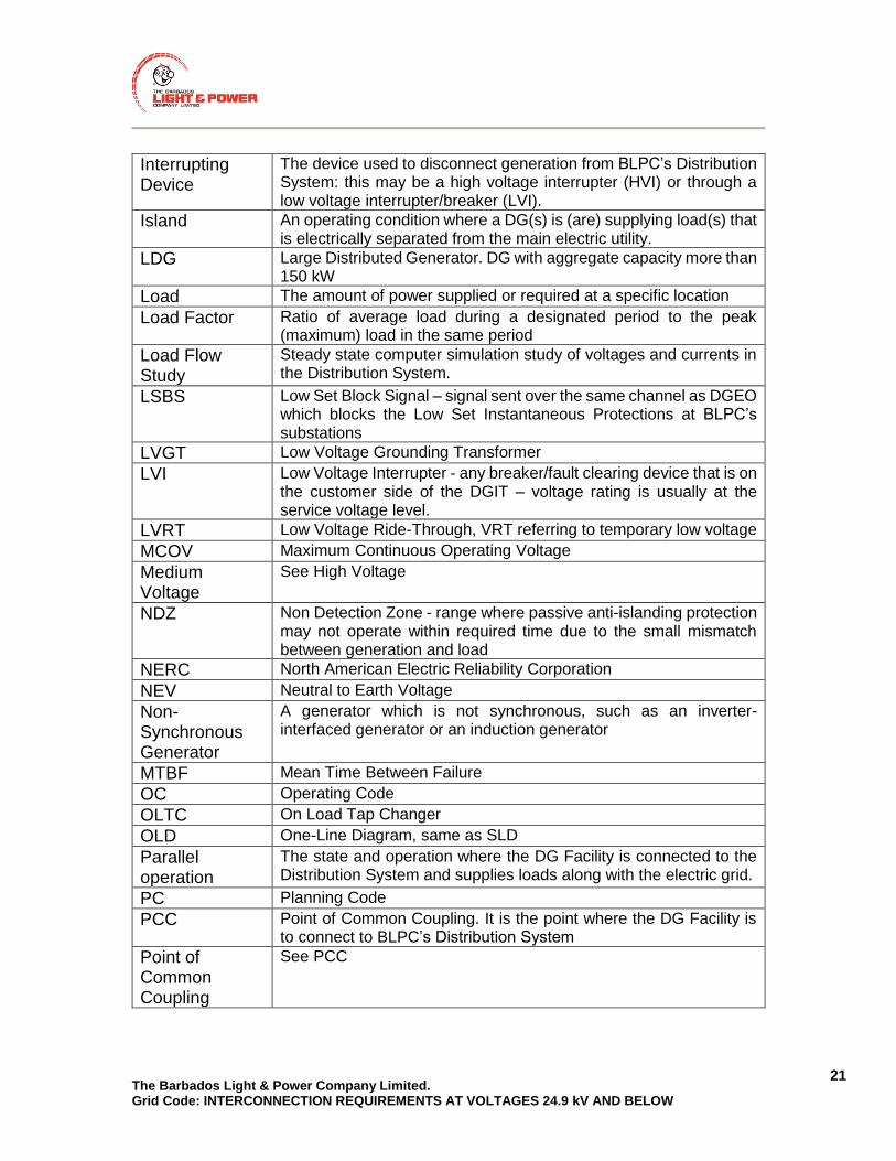
Interrupting Device
The device used to disconnect generation from BLPC’s Distribution System: this may be a high voltage interrupter (HVI) or through a low voltage interrupter/breaker (LVI).
Island An operating condition where a DG(s) is (are) supplying load(s) that is electrically separated from the main electric utility.
LDG Large Distributed Generator. DG with aggregate capacity more than 150 kW
Load The amount of power supplied or required at a specific location
Load Factor Ratio of average load during a designated period to the peak (maximum) load in the same period
Load Flow Study
Steady state computer simulation study of voltages and currents in the Distribution System.
LSBS Low Set Block Signal – signal sent over the same channel as DGEO which blocks the Low Set Instantaneous Protections at BLPC’s substations
LVGT Low Voltage Grounding Transformer
LVI Low Voltage Interrupter - any breaker/fault clearing device that is on the customer side of the DGIT – voltage rating is usually at the service voltage level.
LVRT Low Voltage Ride-Through, VRT referring to temporary low voltage
MCOV Maximum Continuous Operating Voltage
Medium Voltage
See High Voltage
NDZ Non Detection Zone - range where passive anti-islanding protection may not operate within required time due to the small mismatch between generation and load
NERC North American Electric Reliability Corporation
NEV Neutral to Earth Voltage
Non-Synchronous Generator
A generator which is not synchronous, such as an inverter-interfaced generator or an induction generator
MTBF Mean Time Between Failure
OC Operating Code
OLTC On Load Tap Changer
OLD One-Line Diagram, same as SLD
Parallel operation
The state and operation where the DG Facility is connected to the Distribution System and supplies loads along with the electric grid.
PC Planning Code
PCC Point of Common Coupling. It is the point where the DG Facility is to connect to BLPC’s Distribution System
Point of Common Coupling
See PCC

The Barbados Light & Power Company Limited. Grid Code: INTERCONNECTION REQUIREMENTS AT VOLTAGES 24.9 kV AND BELOW
22
Point of Connection
The point where the new DG Facility‘s connection assets or new line expansion assets will be connected to the BLPC’s existing Distribution System
Point of Delivery
The point where the DG is electrically connected to the electric utility for metering purposes.
Point of Disconnection
The point at an accessible location where the disconnect switch used to isolate the DG from the utility is located.
PPA Power Purchase Agreement. LDG Facilities are required to enter into a Power Purchase Agreement with BLPC prior to generating onto the system
Plt A measure of long-term perception of flicker obtained for a two-hour interval (defined in IEC 61000-4-15)
Pst A measure of short-term perception of flicker obtained for a ten minute interval (defined in IEC 61000-4-15)
PSS Power System Stabilizer
Protection Scheme
Protection functions including associated sensors, relays, CTs, VTs, power supplies, intended to protect a Distribution System or interconnected facility.
PQ Power Quality
PT Potential Transformer
PU Pick Up
Resonance A tendency of a system to oscillate at maximum amplitude at certain frequencies, usually resulting in very high voltages and currents.
ROCOF Rate-of-change-of-frequency
RMS Root Mean Square
RTU Remote Terminal Unit
SC Short Circuit Current
SCADA Supervisory Control and Data Acquisition
SDG Small Distributed Generator. DG with aggregate capacity at or less than 150 kW
SER Sequence of Events Recorder
Service Provider
A service Provider is an entity that provides services to other entities
SLD Single Line Diagram
SPS Special Protection Scheme
Stabilized A Distribution System returning to normal frequency and voltage after a disturbance for a period of 5 minutes or as determined by the Wires Owner
Synchronized See Parallel Operation
Synchronous Generator
A generator that is connected directly to BLPC’s Distribution System and rotates synchronously with the system frequency.
Telemeter Transfer of metering data using communication systems
THD Total Harmonic Distortion – a measurement of the harmonic distortion present. It is defined as a ratio of the sum of the powers

The Barbados Light & Power Company Limited. Grid Code: INTERCONNECTION REQUIREMENTS AT VOLTAGES 24.9 kV AND BELOW
23
of all harmonic components to the power of the fundamental frequency
TOV Temporary Overvoltage – oscillatory power frequency overvoltages of relatively long duration, from a few cycles to hours.
Transmission System
Any power line facilities under the operating authority of the Wires Owner usually operating at higher than 24.9 kV voltages, line to line.
Transfer Trip A signal sent over communication channels from upstream devices commanding the DG to disconnect from Barbados Light & Power Company Limited's Distribution System.
Trip Time The time between the start of the abnormal condition to the time where the system disconnects and ceases to energize the Distribution System.
TS Transmission Substation. An electrical station that is used to step down 69 kV voltage to a sub-transmission voltage for distribution at 24.9 kV to the end use customer and DS stations.
TT See Transfer Trip
Type Test Test performed on a sample of a particular model or device to verify its operation and design.
UTC Coordinated Universal Time
UVRT Undervoltage Ride-Through, same as LVRT
Variable DG A DG whose maximum active power output depends on prevailing conditions, such as insolation or wind speed
VR Voltage Regulator
VRT Voltage Ride-Through describes the capability of withstanding abnormal system voltage for a given time duration. The general term comprises both HVRT and LVRT.
VT Voltage Transformer
Wires Owner Utility which owns and/or operates the Distribution System.

The Barbados Light & Power Company Limited. Grid Code: INTERCONNECTION REQUIREMENTS AT VOLTAGES 24.9 kV AND BELOW
24
The Grid Code
The Barbados Light & Power Company Limited. Grid Code: INTERCONNECTION REQUIREMENTS AT VOLTAGES 24.9 kV AND BELOW
25
2. PLANNING CODE FOR GENERATORS ≤ 150 KW
2.1 INTRODUCTION
In order to assess whether the connection of new users or the modification of existing connections will impact the stability and security of Barbados’ power system, a clear procedure is required for exchanging information between users and BLPC. In addition, BLPC needs information from users so that it can plan for the long-term development of the power system. Development of the BLPC Transmission and Distribution System will arise for a number of reasons, including but not limited to:
1. Connection of new generators or consumers to the network.
2. Modification of existing connections to the grid.
3. Longer-term changes to generation and consumption patterns due to technical, economic and environmental changes.
4. The cumulative effects of the above changes.
As a result of these changes BLPC must carry out planning and development studies, to determine the need to invest in new network infrastructure or modify existing connections, for the benefit of all network users.
To plan for these changes, the Planning Code sets out planning requirements and application procedures for generators wishing to connect to the network and for the modification of existing connections.
2.2 OBJECTIVES
The objectives of the Planning Code are:
1. To ensure that BLPC has sufficient information for the planning and development of the Transmission and Distribution System.
2. To describe the application procedure for generators wishing to connect to BLPC’s network.
3. To set out the information and application forms required by BLPC from generators wishing to connect to BLPC’s network.
The Barbados Light & Power Company Limited. Grid Code: INTERCONNECTION REQUIREMENTS AT VOLTAGES 24.9 kV AND BELOW
26
2.3 SCOPE
This section of the Planning Code applies to all DG Facilities with an aggregate capacity at or less than 150 kW, referred to in this section as Small Distributed Generators (SDG).
2.4 OVERVIEW OF CONNECTION APPLICATION PROCESS
To connect an SDG Facility to BLPC’s Distribution System or modify an existing connection, the following steps shall be followed:
1. The (prospective or existing) SDG Owner shall submit an Application for Proposed Connection or Modification of SDG (APC-S) to BLPC along with an Application Validation document from the Division of Energy & Telecommunications (DOET) and GEED approved Single Line diagram.
2. BLPC shall carry out a review of the APC-S submitted by the SDG Owner.
3. BLPC shall inform the SDG Owner within six (6) weeks if the application has been approved and whether any modifications to the proposed connection are required.
4. If the application is approved by BLPC, a Power Purchase Agreement (PPA) can be agreed between the SDG Owner and BLPC. The PPA shall incorporate the technical terms, rates and conditions for power purchase
5. Once all other statutory permissions have been granted including the ELPA licensing and Town and Country Planning permission where required, the PPA can be executed between the SDG Owner and BLPC.
6. The SDG Owner may proceed to install the SDG generator.
7. The SDG Owner shall submit all remaining relevant documents and demonstrate that the SDG is in compliance with the Connection Code and the requirements of the Electric Light & Power Act 2013 (ELPA).
8. Within six (6) weeks of receiving notification from the customer that the installation has been completed, BLPC will carry out inspections and tests in accordance with Appendix 8.5 and will advise the applicant in writing whether or not the proposed SDG qualifies for interconnection to BLPC’s Grid.
9. If BLPC has given its written permission, the SDG may be connected to BLPC’s Distribution System.

The Barbados Light & Power Company Limited. Grid Code: INTERCONNECTION REQUIREMENTS AT VOLTAGES 24.9 kV AND BELOW
27
The steps are described in more detail below. The procedure is also illustrated in Appendix B, section 10.1.
2.5 APPLICATION FOR PROPOSED CONNECTION
1. Users proposing the connection of a new SDG or the modification of an existing SDG shall send an Application for Proposed Connection or Modification of SDG (APC-S) to BLPC along with an Application Validation document from the Division of Energy and Telecommunications and GEED approved Single Line Diagram.
2. The APC-S form is found in Appendix 11. The required attachments mentioned in the APC-S form shall be submitted together with the completed form; this includes certification documentation from the generator manufacturer in accordance with Section 4.7.
3. Applicants shall pay an application fee in accordance with the Service charge Schedule K-8 approved by the Fair Trading Commission (FTC) and located on the FTC’s website at:
http://www.ftc.gov.bb/library/blip_app/2010-02-17_final_tariff_ORDER_2009_ftc
_and_barbados_light_and_power_co_ltd.pdf .
2.6 APPLICATION REVIEW
1. Upon receiving the APC-S for an SDG Facility, BLPC will review the application to assess the impact of the SDG on the operation of BLPC’s Transmission and Distribution System.
2. If the SDG is found to negatively impact the stability and/or security of BLPC’s Transmission and Distribution System, modifications may need to be made to the proposed connection.
3. BLPC may also refuse the application for connection of the SDG if BLPC determines that the SDG threatens the security or stability of BLPC’s Grid, and modifications are deemed insufficient as mitigation measures. The rationale shall be provided to the SDG in case of refusal.
4. BLPC shall inform the SDG if the application has been approved and whether any modifications may be necessary within six (6) weeks of receipt of the APC-S.
5. Any necessary modifications shall be specified in all required detail by BLPC. If there are any, approval of the application covers only the
The Barbados Light & Power Company Limited. Grid Code: INTERCONNECTION REQUIREMENTS AT VOLTAGES 24.9 kV AND BELOW
28
modified proposed connection; re-submission of a modified application is not necessary if the SDG follows the modifications.
6. Approval of the SDG application shall be valid for twelve (12) months from date of approval.
2.7 FURTHER DOCUMENTS REQUIRED FOR CONNECTION
After the application for proposed connection has been approved by BLPC, but before interconnection of the SDG, the SDG shall submit to BLPC the following documents:
1. A certificate for general liability insurance with a minimum coverage as specified in the Power Purchase Agreement.
2. A “GEED” certificate approving the SDG for interconnection to BLPC’s Grid.
3. If applicable, a licence issued in accordance with the Electric Light & Power Act 2013 (ELPA) of the laws of Barbados.
2.8 INTERCONNECTION
1. Within six (6) weeks of receiving notification from the customer that the installation has been completed, BLPC will carry out inspections and tests in accordance with Appendix 8.5.
2. BLPC will advise the applicant in writing whether or not the proposed interconnection of the SDG qualifies for interconnection to BLPC’s Grid.
3. Once the SDG Owner has received confirmation from BLPC and correct metering is installed, the SDG may be connected to BLPC’s Grid.
2.9 DATA FOR SYSTEM PLANNING
1. After installation of the SDG, BLPC may require additional data or information from the SDG Owner for system planning purposes.
2. If BLPC considers that this information is required, then the SDG Owner shall submit the information to BLPC without delay.
2.10 VALIDATION AND VERIFICATION OF DATA
1. After any data submission from the SDG Owner to BLPC, BLPC may require additional information that will allow BLPC to verify the data that has been submitted.

The Barbados Light & Power Company Limited. Grid Code: INTERCONNECTION REQUIREMENTS AT VOLTAGES 24.9 kV AND BELOW
29
2. In case of doubt, the SDG Owner shall provide access to the SDG facility to BLPC for visual inspection and/or further testing.

The Barbados Light & Power Company Limited. Grid Code: INTERCONNECTION REQUIREMENTS AT VOLTAGES 24.9 kV AND BELOW
30
3. PLANNING CODE FOR GENERATORS > 150 KW
3.1 INTRODUCTION
In order to assess whether the connection of new users or the modification of existing connections will impact the stability and security of Barbados’ power system, a clear procedure is required for exchanging information between users and BLPC. In addition, BLPC needs information from users so that it can plan for the long-term development of the power system. Development of the BLPC Transmission and Distribution System will arise for a number of reasons, including but not limited to:
1. Connection of new generators or consumers to the network.
2. Modification of existing connections to the grid.
3. Longer-term changes to generation and consumption patterns due to technical, economic and environmental changes.
4. The cumulative effects of the above changes.
As a result of these changes BLPC must carry out planning and development studies, to determine the need to invest in new network infrastructure or modify existing connections, for the benefit of all network users.
To plan for these changes, the Planning Code sets out planning requirements and application procedures for generators wishing to connect to the network and for the modification of existing connections.
3.2 OBJECTIVES
The objectives of the Planning Code are:
1. To ensure that BLPC has sufficient information for the planning and development of the Transmission and Distribution System.
2. To describe the application procedure for generators wishing to connect to BLPC’s network.
3. To set out the information and application forms required by BLPC from generators wishing to connect to BLPC’s network.

The Barbados Light & Power Company Limited. Grid Code: INTERCONNECTION REQUIREMENTS AT VOLTAGES 24.9 kV AND BELOW
31
3.3 SCOPE
This section of the Planning Code applies to all DG facilities with an aggregate capacity greater than 150 kW, referred to in this section as Large Distributed Generators (LDG).
3.4 OVERVIEW OF CONNECTION APPLICATION PROCESS
To connect an LDG Facility to BLPC’s Transmission and Distribution System or modify an existing connection, the following steps shall be followed:
1. The (prospective or existing) LDG Owner shall submit an Application for Proposed Connection or Modification of LDG (APC-L) to BLPC along with a GEED Approved Single Line Diagram and Application Validation document from the Division of Energy and Telecommunications.
2. BLPC shall carry out a Connection Impact Assessment (CIA) for LDG (CIA-L) based on the APC-L submitted by the LDG Owner.
3. BLPC shall make the LDG Owner a Connection Offer (GCO-L) based on the CIA-L within six (6) months of receiving the APC-L.
4. If the Connection Offer is accepted by the LDG Owner, a Power Purchase Agreement (PPA) can be agreed between the LDG Owner and BLPC. The PPA shall incorporate the technical terms as specified in the GCO-L, and the negotiated rates and conditions for power purchase.
5. The PPA shall be submitted to the FTC for approval.
6. Once approved by FTC and all other statutory permissions have been granted including the ELPA licensing and Town and Country Planning permission, the PPA can be executed between the LDG Owner and BLPC.
7. The LDG Owner may proceed to install the LDG.
8. The LDG Owner shall submit all remaining relevant documents and demonstrate that the LDG is in compliance with the Connection Code and the requirements of the Electric Light & Power Act 2013 (ELPA).
9. Once installation has been completed, the LDG shall be tested and commissioned according to the requirements set out in this document (see section 5.9). Documentation of test results shall be submitted to BLPC.
The Barbados Light & Power Company Limited. Grid Code: INTERCONNECTION REQUIREMENTS AT VOLTAGES 24.9 kV AND BELOW
32
10. If BLPC has given its written permission, the LDG may be connected to BLPC’s Transmission and Distribution System.
The steps are described in more detail below. The procedure is also illustrated in Appendix B, section 10.2.
3.5 APPLICATION FOR PROPOSED CONNECTION
1. Users proposing the connection of a new LDG or the modification of an existing LDG shall send an Application for Proposed Connection or Modification of LDG (APC-L) to BLPC.
2. The APC-L form is found in Appendix 11. The required attachments mentioned in the APC-L form shall be submitted together with the completed form; this includes grid code compliance documentation from the generator manufacturer as applicable.
3. Applicants shall pay an application fee in accordance with the Service charge Schedule K-8 approved by the Fair Trading Commission (FTC) and located on the FTC’s website at
http://www.ftc.gov.bb/library/blip_app/2010-02-17_final_tariff_ORDER_2009_ftc
_and_barbados_light_and_power_co_ltd.pdf .
3.6 CONNECTION IMPACT ASSESSMENT
1. Upon receiving the APC-L for an LDG Facility, BLPC will carry out a Connection Impact Assessment for LDG (CIA-L) to assess the impact of the LDG on the operation of BLPC’s Transmission and Distribution System.
2. If the LDG is found to negatively impact the stability and/or security of BLPC’s Transmission and Distribution System, modifications to the proposed connection shall be required to mitigate impacts.
3. BLPC may also refuse the application for connection of the LDG if BLPC determines that the LDG threatens the security or stability of BLPC’s Grid, and modifications are deemed insufficient as mitigation measures. The rationale shall be provided to the LDG in case of refusal.

The Barbados Light & Power Company Limited. Grid Code: INTERCONNECTION REQUIREMENTS AT VOLTAGES 24.9 kV AND BELOW
33
3.7 GRID CONNECTION OFFER
1. Based on the CIA-L, BLPC shall make the LDG Owner a Grid Connection Offer for LDG (GCO-L). The GCO-L shall contain:
a) Details of how the connection is to be made, including details of the plant and apparatus that will be required to implement the connection.
b) A description of any modifications to the APC-L determined by BLPC to be necessary.
c) An estimate of any charges made by BLPC to the LDG Owner for the connection.
2. BLPC shall make the GCO-L not more than six (6) months after receipt of the APC-L.
3. The GCO-L shall be valid for twelve (12) months after the date of submission from BLPC to the LDG owner.
3.8 POWER PURCHASE AGREEMENT
1. If the LDG Owner accepts the GCO-L within its validity period, BLPC and the LDG Owner may negotiate a Power Purchase Agreement (PPA).
2. The PPA shall regulate the commercial terms for the purchase of energy by BLPC from the LDG Owner. The PPA shall also incorporate the technical terms as specified in the GCO-L.
3. Once the LDG Owner and BLPC have agreed on the terms and conditions of the PPA, the PPA is submitted to the FTC for approval.
4. Once approved by FTC and all other statutory permissions have been granted including the ELPA licensing and Town and Country Planning permission, the PPA can be executed between the LDG Owner and BLPC.
5. The LDG Owner may install the LDG.
The Barbados Light & Power Company Limited. Grid Code: INTERCONNECTION REQUIREMENTS AT VOLTAGES 24.9 kV AND BELOW
34
3.9 FURTHER DOCUMENTS REQUIRED FOR CONNECTION
Once the PPA has been signed by the LDG Owner and BLPC, but before interconnection of the LDG, the LDG shall submit to BLPC the following documents:
1. A certificate for general liability insurance with a minimum coverage to be specified in the PPA.
2. A “GEED” certificate approving the LDG for interconnection to BLPC’s Grid.
3. A licence issued in accordance with the Electric Light & Power Act 2013 (ELPA) of the laws of Barbados.
4. The as-built design of all power equipment, protection, control, and metering systems used at the LDG Facility interconnection.
5. Documentation on interconnection protection as outlined in Section 5.4.20.
3.10 INTERCONNECTION
1. The LDG Facility interconnecting to BLPC’s Transmission or Distribution System must have a registered engineer, licensed in Barbados, declare (stamp and seal) that the LDG Facility has been designed, tested and constructed in accordance with the requirements of this document, BLPC’s site-specific requirements, prudent utility practice and all applicable standards and codes.
2. Commissioning and verification shall be in accordance with the requirements in Section 5.9.
3. BLPC will advise the applicant in writing whether or not the proposed interconnection of the LDG qualifies for interconnection to BLPC’s Grid.
4. Once the LDG Owner has received confirmation from BLPC, the LDG may be connected to BLPC’s Grid.
3.11 DATA FOR SYSTEM PLANNING
1. After installation of the LDG, BLPC may require additional data or information from the LDG Owner for system planning purposes.
2. If BLPC considers that this information is required, then the LDG Owner shall submit the information to BLPC without delay.
The Barbados Light & Power Company Limited. Grid Code: INTERCONNECTION REQUIREMENTS AT VOLTAGES 24.9 kV AND BELOW
35
3.12 VALIDATION AND VERIFICATION OF DATA
1. After any data submission from the LDG Owner to BLPC, BLPC may require additional information that will allow BLPC to verify the data that has been submitted.
2. In case of doubt, the LDG Owner shall provide access to the LDG facility to BLPC for visual inspection.
The Barbados Light & Power Company Limited. Grid Code: INTERCONNECTION REQUIREMENTS AT VOLTAGES 24.9 kV AND BELOW
36
4. CONNECTION CODE FOR GENERATORS ≤ 150 KW
4.1 INTRODUCTION
This section provides the technical requirements to be met by DG facilities with aggregate capacity at or less than 150 kW, referred to as Small Distributed Generators (“SDG”). This section lists typical conditions and response to abnormal conditions that the SDG is required to meet. The SDG system must comply with the specific requirements as detailed in this document. Information on the general characteristics of BLPC’s Distribution System can be found in Section 9.
4.2 GENERAL REQUIREMENTS
4.2.1 POINT OF DELIVERY – RESPONSIBILITIES
The Point of Delivery must be identified on the renewable system Electrical One-Line Diagram sent with the APC-S. BLPC will co-ordinate the design, construction, maintenance and operation of the facilities on the BLPC side of the PCC. The Customer-Generator is responsible for the design, construction, maintenance and operation of the facilities on the Customer-Generator side of the PCC.
4.2.2 POINT OF DISCONNECTION – SAFETY
A lockable AC disconnecting device preferably of the knife blade type is required to provide a point of isolation between the SDG and BLPC’s Grid for safe working purposes. It should be installed by the Customer-Generator in a visible and accessible location near to BLPC’s revenue meter or the Point of Delivery, whichever is acceptable to BLPC. A sample disconnect switch is shown in Appendix 8.3.
4.2.3 INTERCONNECTION GROUNDING
The SDG must be grounded as per the manufacturers’ recommendations and according to the requirements of the GEED. BLPC provides a grounded neutral service conductor.

The Barbados Light & Power Company Limited. Grid Code: INTERCONNECTION REQUIREMENTS AT VOLTAGES 24.9 kV AND BELOW
37
4.2.4 PHASING
The SDG must connect rotating machines as required to match the phase sequence and direction of rotation of BLPC Distribution System.
4.2.5 DEVICE RATING
Device rating for main panel shall be in accordance with the latest version of the NEC Article 705.12. This article grants permission to interconnect interactive inverters on either the supply side or load side of distribution equipment.
4.3 PERFORMANCE REQUIREMENTS
4.3.1 VOLTAGE FLICKER
Voltage Flicker is an increase or decrease in voltage over a short period of time and is normally associated with fluctuating loads or motor starting. A Flicker problem is site-specific and depends on the characteristics of the changes in load. Flicker is considered objectionable when it either causes a modulation of lighting levels sufficient to be irritating to humans or it causes equipment to malfunction. The SDG shall not cause objectionable Flicker for other customers on BLPC’s Grid. The SDG is considered compliant if it conforms to IEC 61000-3-3 or IEC 61000-3-11 (where any of these is applicable), and the long-term flicker coefficient (Plt) is not larger than 0.5.
4.3.2 HARMONIC DISTORTION
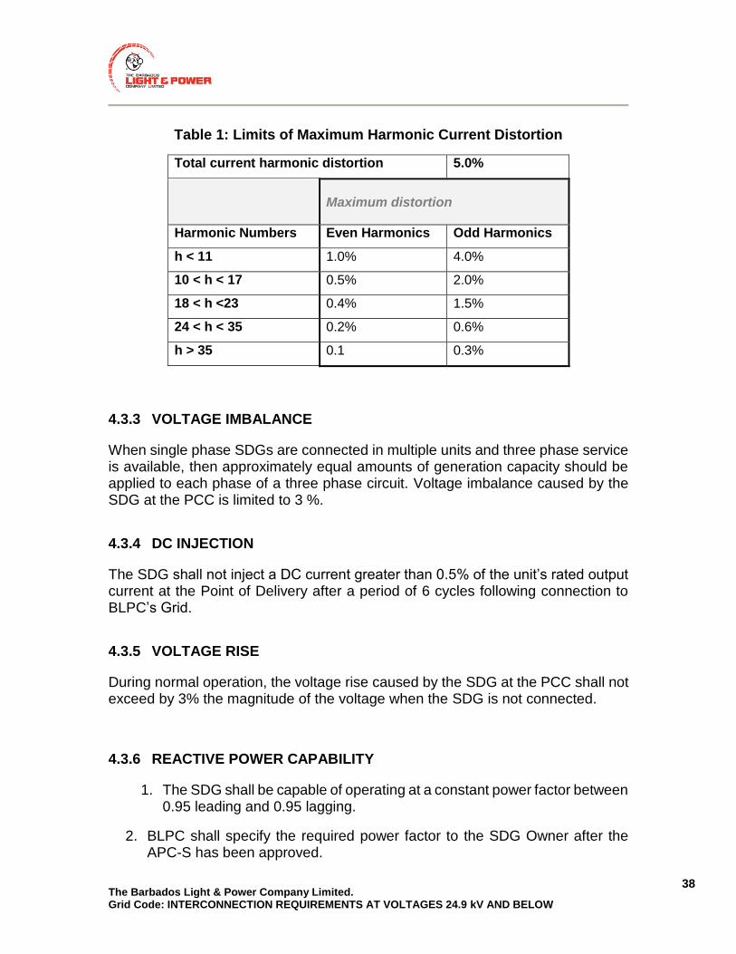
SDGs are expected to comply with IEEE Standard 519, IEC 61000-3-2, IEC TS 61000-3-4, or IEC 61000-3-12 current distortion limits with regard to harmonic current injection into BLPC’s Grid. The harmonic current injection arising from the SDG shall not exceed the values listed in Table 1 (excluding any harmonic currents associated with harmonic voltage distortion present on BLPC’s Grid without the SDG connected). Total current harmonic distortion shall not exceed 5% of rated current.
The Barbados Light & Power Company Limited. Grid Code: INTERCONNECTION REQUIREMENTS AT VOLTAGES 24.9 kV AND BELOW
38
Table 1: Limits of Maximum Harmonic Current Distortion
Total current harmonic distortion 5.0%
Maximum distortion
Harmonic Numbers Even Harmonics Odd Harmonics
h < 11 1.0% 4.0%
10 < h < 17 0.5% 2.0%
18 < h <23 0.4% 1.5%
24 < h < 35 0.2% 0.6%
h > 35 0.1 0.3%
4.3.3 VOLTAGE IMBALANCE
When single phase SDGs are connected in multiple units and three phase service is available, then approximately equal amounts of generation capacity should be applied to each phase of a three phase circuit. Voltage imbalance caused by the SDG at the PCC is limited to 3 %.
4.3.4 DC INJECTION
The SDG shall not inject a DC current greater than 0.5% of the unit’s rated output current at the Point of Delivery after a period of 6 cycles following connection to BLPC’s Grid.
4.3.5 VOLTAGE RISE
During normal operation, the voltage rise caused by the SDG at the PCC shall not exceed by 3% the magnitude of the voltage when the SDG is not connected.
4.3.6 REACTIVE POWER CAPABILITY
1. The SDG shall be capable of operating at a constant power factor between 0.95 leading and 0.95 lagging.
2. BLPC shall specify the required power factor to the SDG Owner after the APC-S has been approved.

The Barbados Light & Power Company Limited. Grid Code: INTERCONNECTION REQUIREMENTS AT VOLTAGES 24.9 kV AND BELOW
39
4.3.7 UNDER-VOLTAGE AND OVER-VOLTAGE RIDE THROUGH
1. The SDG Facility interconnection protection scheme shall have the capability of detecting abnormal voltages.
2. Three phase inverter systems shall detect each individual phase to neutral voltage on a grounded Wye system or each individual phase to phase voltage on an ungrounded Wye or delta system.
3. Single phase inverter systems shall detect the phase to neutral voltage if connected to the neutral conductor.
4. Single phase inverter systems connected phase to phase (not connected to the neutral conductor) shall detect the phase to phase voltage.
5. In the case of under-voltage for synchronous generators, the SDG Facility shall not disconnect from the grid if the voltage as a percentage of the nominal voltage value remains above the lower blue line in Figure 1 (in the case of three-phase generators, the voltage refers to the smallest line-to-neutral or line-to-line voltage at the generator terminal); the points which define the lower blue line in Figure 1 are listed in Table 2.
6. In the case of under-voltage for non-synchronous generators, the SDG Facility shall not disconnect from the grid if the voltage as a percentage of the nominal voltage value remains above the lower blue line in Figure 2 (in the case of three-phase generators, the voltage refers to the smallest line-to-neutral or line-to-line voltage at the generator terminal); the points which define the lower blue line in Figure 2 are listed in Table 2.
7. In Figure 1 and Figure 2 the time t=0 seconds marks the beginning of the voltage drop (where the voltage first falls below 90% of the nominal voltage).
8. In the case of over-voltage, the SDG Facility shall not disconnect for 0.92 s if the voltage rises to between 110% and 120% of its nominal value. This is represented by the upper blue line in Figure 1 and Figure 2; in the case of three-phase generators the voltage refers to the highest line-to-line voltage at the generator terminal.
9. If the active power production is reduced during the fault, it shall be ramped up back to the pre-fault value after fault clearance with a ramp rate of at least 10% of the rated power per second.

The Barbados Light & Power Company Limited. Grid Code: INTERCONNECTION REQUIREMENTS AT VOLTAGES 24.9 kV AND BELOW
40
Figure 1 (illustrative): Voltage Ride Through curves for synchronous
generators ≤ 150 kW, and trip curves according to section 4.4.3.
Figure 2 (illustrative): Voltage Ride Through curves for non-synchronous
generators ≤ 150 kW, and trip curves according to section 4.4.3.
0
20
40
60
80
100
120
140
-500 0 500 1000 1500 2000 2500 3000 3500
Vo
ltag
e in
pe
r ce
nt
(%)
Time in milliseconds
Voltage Ride Through
Trip
must not disconnect
may disconnect
must disconnect
must disconnect
0
20
40
60
80
100
120
140
-500 1500 3500 5500 7500 9500 11500 13500 15500
Vo
ltag
e in
pe
r ce
nt
(%)
Time in milliseconds
Voltage Ride Through
Trip
must not disconnect
may
dis
con
nec
t
must disconnect
must disconnect
0

The Barbados Light & Power Company Limited. Grid Code: INTERCONNECTION REQUIREMENTS AT VOLTAGES 24.9 kV AND BELOW
41
Table 2: Under-Voltage Ride Through curve point definitions for SDG
UVRT points for synchronous SDG UVRT points for non-synchronous SDG
Time (milliseconds)
Voltage (%) Time (milliseconds)
Voltage (%)
0 0 0 50
200 0 10000 50
200 20 10000 90
500 20
500 40
1500 90
4.3.8 UNDER FREQUENCY AND OVER FREQUENCY RIDE THROUGH
1. The SDG Facility interconnection protection scheme shall have the capability of detecting abnormal frequencies shown below in Table 3.
2. The SDG Facility shall not disconnect due to frequency deviation during abnormal frequencies within the ranges and within the time limits marked “Ride Through” in Table 3. The same conditions are illustrated in Figure 3.
3. The times in Table 3 shall be measured from the instant when the measured frequency has crossed the respective threshold.
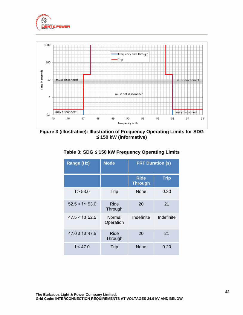
The Barbados Light & Power Company Limited. Grid Code: INTERCONNECTION REQUIREMENTS AT VOLTAGES 24.9 kV AND BELOW
42
Figure 3 (illustrative): Illustration of Frequency Operating Limits for SDG
≤ 150 kW (informative)
Table 3: SDG ≤ 150 kW Frequency Operating Limits
Range (Hz) Mode FRT Duration (s)
Ride Through
Trip
f > 53.0 Trip None 0.20
52.5 < f ≤ 53.0 Ride Through
20 21
47.5 < f ≤ 52.5 Normal Operation
Indefinite Indefinite
47.0 ≤ f ≤ 47.5 Ride Through
20 21
f < 47.0 Trip None 0.20
0,1
1
10
100
1000
45 46 47 48 49 50 51 52 53 54 55
Tim
e in
se
con
ds
Frequency in Hz
Frequency Ride Through
Trip
must not disconnect
may disconnect
must disconnect
may disconnect
must disconnect
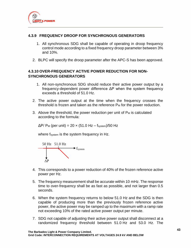
The Barbados Light & Power Company Limited. Grid Code: INTERCONNECTION REQUIREMENTS AT VOLTAGES 24.9 kV AND BELOW
43
4.3.9 FREQUENCY DROOP FOR SYNCHRONOUS GENERATORS
1. All synchronous SDG shall be capable of operating in droop frequency control mode according to a fixed frequency droop parameter between 3% and 10%.
2. BLPC will specify the droop parameter after the APC-S has been approved.
4.3.10 OVER-FREQUENCY ACTIVE POWER REDUCTION FOR NON-
SYNCHRONOUS GENERATORS
1. All non-synchronous SDG should reduce their active power output by a frequency-dependent power difference ΔP when the system frequency exceeds a threshold of 51.0 Hz.
2. The active power output at the time when the frequency crosses the threshold is frozen and taken as the reference PM for the power reduction.
3. Above the threshold, the power reduction per unit of PM is calculated according to the formula: ΔP/ PM (per unit) = 20 × (51.0 Hz – fsystem)/50 Hz where fsystem is the system frequency in Hz.
4. This corresponds to a power reduction of 40% of the frozen reference active power per Hz.
5. The frequency measurement shall be accurate within 10 mHz. The response time to over-frequency shall be as fast as possible, and not larger than 0.5 seconds.
6. When the system frequency returns to below 51.0 Hz and the SDG is then capable of producing more than the previously frozen reference active power, the active power may be ramped up to the maximum with a ramp rate not exceeding 10% of the rated active power output per minute.
7. SDG not capable of adjusting their active power output shall disconnect at a randomized frequency threshold between 51.0 Hz and 53.0 Hz. The
fsystem
ΔP
51.0 Hz 50 Hz

The Barbados Light & Power Company Limited. Grid Code: INTERCONNECTION REQUIREMENTS AT VOLTAGES 24.9 kV AND BELOW
44
randomization may be performed by the manufacturer, such that a fixed threshold may be built into the generation units.
4.4 PROTECTION REQUIREMENTS
4.4.1 INTERCONNECTION PROTECTION FUNCTION REQUIREMENTS
The SDG shall incorporate the following protective functions:- (i) AC disconnecting; (ii) Anti-Islanding; (iii) Automatic synchronizing (generators with stand-alone capability); (iv) Under-voltage trip (on each phase for 3-phase equipment); (v) Over-voltage trip (on each phase for 3-phase equipment); (vi) Instantaneous over-current trip (on each phase for 3-phase equipment); (vii) Timed over-current trip (on each phase for 3-phase equipment); (viii) Under-frequency trip; and (ix) Over-frequency trip.
4.4.2 OVER-CURRENT PROTECTION
The SDG must detect and promptly cease to energize for over-current fault conditions within its system.
4.4.3 UNDER-VOLTAGE AND OVER-VOLTAGE PROTECTION
1. Every grid-tied SDG shall have under/over-voltage protection and, on detection of such voltage, shall cease to energize within the timeframe indicated in Table 4.
2. Three phase inverter systems shall detect each individual phase to neutral voltage on a grounded Wye system or each individual phase to phase voltage on an ungrounded Wye or delta system for the purposes of Table 4.
3. Single phase inverter systems shall detect the phase to neutral voltage if connected to the neutral conductor.
4. Single phase inverter systems connected phase to phase (not connected to the neutral conductor) shall detect the phase to phase voltage.

The Barbados Light & Power Company Limited. Grid Code: INTERCONNECTION REQUIREMENTS AT VOLTAGES 24.9 kV AND BELOW
45
5. The SDG shall not attempt to regulate the voltage or adversely affect the voltage at the Point of Delivery.
6. The SDG Facility shall reconnect once the conditions in Section 4.4.5 or Section 4.4.6 are met.
Table 4: SDG ≤ 150 kW Under- and Over-Voltage Protection Trip Times
Range (% of nominal Voltage) Trip Time (seconds)
synchronous SDG
non-synchronous SDG
V > 120 0.20 0.20
110 <V ≤ 120 1.0 1.0
50<V <= 90 2.0 11.0
V<50 1.2 0.20
4.4.4 UNDER FREQUENCY AND OVER FREQUENCY PROTECTION
1. The SDG Facility interconnection protection scheme shall have the capability of detecting abnormal frequencies shown in Table 3.
2. The SDG Facility shall disconnect from BLPC’s Distribution System in the clearing times specified in Table 3 under “Trip”.
3. The times in Table 3 shall be measured from the instant when the measured frequency has crossed the respective threshold.
4. If the SDG has ceased to energize due to over/under frequency conditions, the SDG Facility shall reconnect only once the conditions in Section 4.4.6 are met.
The Barbados Light & Power Company Limited. Grid Code: INTERCONNECTION REQUIREMENTS AT VOLTAGES 24.9 kV AND BELOW
46
4.4.5 SHORT-TIME CONTINGENCY
1. Network faults that (a) lead to the disconnection of the SDG (b) and where the violation of the normal operating ranges of voltage (between 90% and 110% of its nominal value) and frequency (between 47.5 Hz and 52.5 Hz) is shorter than 3 seconds shall be called short-time contingencies.
2. After short-time contingencies, the SDG may reconnect to the grid if voltage and frequency continuously remain within the normal operating ranges for at least 5 seconds.
3. The active power ramp of the SDG reconnecting after short-time contingencies shall be at least 10% of rated power per second.
4. If the conditions stated under (1) and (2) are not fulfilled, the normal reconnection procedure applies as outlined in Section 4.4.6.
4.4.6 RECONNECTION AFTER PROTECTION TRIPPING
1. After disconnection due to protection tripping, the SDG shall reconnect to the grid when (a) the voltage continuously remains within 90% to 110% of its nominal value and, at the same time, (b) the frequency continuously remains between 47.5 Hz and 52.5 Hz for at least 60 seconds.
2. The active power ramp of the reconnected SDG shall not exceed 10% of rated power per second until (a) the momentary maximum active power output or dispatched active power output is reached (uncontrollable SDG) (b) the dispatched active power output is reached (controllable SDG)
3. If the active power ramp cannot be limited, reconnection shall be delayed by a random time (specific to each SDG unit) interval between 1 and 10 minutes.

The Barbados Light & Power Company Limited. Grid Code: INTERCONNECTION REQUIREMENTS AT VOLTAGES 24.9 kV AND BELOW
47
4.4.7 ANTI-ISLANDING
For an unintentional island condition, where the SDG energizes a portion of BLPC’s Grid, the SDG shall detect the island condition and cease to energize BLPC’s Grid within a maximum of five seconds after the formation of the island.
4.4.8 INTERRUPTING DEVICE RATINGS
The design of the SDG must consider the fault current contributions from both generation sources to ensure that all circuit fault interrupters are adequately sized.
4.5 OPERATING REQUIREMENTS
4.5.1 SYNCHRONIZATION
The SDG that can generate an AC Voltage Waveform independent of BLPC’s Grid shall be connected in parallel only in combination with the SDG’s synchronizing capabilities. The SDG shall synchronize to BLPC’s Grid while meeting the Flicker requirements of Section 4.3.1. Synchronization may occur once BLPC’s Grid is stabilized and normal operating ranges have been attained for both the voltage (between 90% and 110% of its nominal value) and the frequency (between 47.5 Hz and 52.5 Hz).
4.5.2 GRID-TIED INVERTERS
Grid-tied inverters are required to produce a true sine wave output of 50 Hz frequency, be synchronous with BLPC’s Grid and comply with the requirements of this document. Note that systems comprising grid-tied inverters with battery backup are configured differently and are more complex than battery-less grid-tied systems. In the interest of safety, the designs of interconnection and meter configurations for battery back-up grid-tied systems must be approved by GEED and the BLPC prior to installation.
4.6 METERING REQUIREMENTS
BLPC will furnish metering to measure separately the energy supplied from BLPC’s Grid to the customer and the energy supplied to BLPC’s Grid by the customer whose SDG has been approved by BLPC. For each service interconnected, the SDG Owner must also make provision for the appropriate meter socket base(s) or other appropriate metering facilities required to measure the total energy generated by the SDG and energy used by the SDG Owner. The
The Barbados Light & Power Company Limited. Grid Code: INTERCONNECTION REQUIREMENTS AT VOLTAGES 24.9 kV AND BELOW
48
required meter(s) will be installed by BLPC. Please refer to the Metering and Meter Installations section of BLPC’s Information and Requirements Booklet. All metering locations must be readily accessible to BLPC personnel for the purposes of maintenance and regular meter reading.
4.6.1 METERING FOR SDG
The two metering configurations for grid-tied SDGs are as follows:
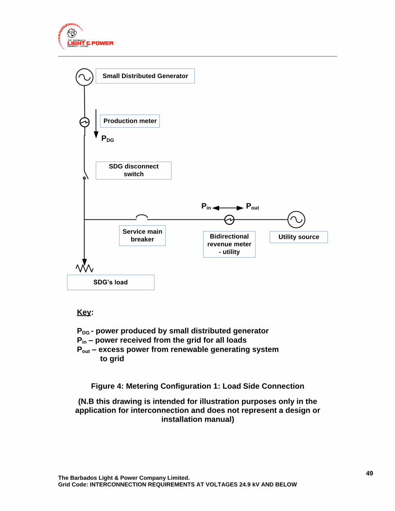
The Barbados Light & Power Company Limited. Grid Code: INTERCONNECTION REQUIREMENTS AT VOLTAGES 24.9 kV AND BELOW
49
Small Distributed Generator
Service main
breaker Utility sourceBidirectional
revenue meter
- utility
Production meter
Pin Pout
SDG’s load
SDG disconnect
switch
Key:
PDG - power produced by small distributed generator
Pin – power received from the grid for all loads
Pout – excess power from renewable generating system
to grid
PDG
Figure 4: Metering Configuration 1: Load Side Connection
(N.B this drawing is intended for illustration purposes only in the application for interconnection and does not represent a design or
installation manual)

The Barbados Light & Power Company Limited. Grid Code: INTERCONNECTION REQUIREMENTS AT VOLTAGES 24.9 kV AND BELOW
50
Small Distributed Generator
Service main
breaker
Utility source
revenue meter
- utility
Production meter
Pin
PDG
SDG’s load
SDG disconnect
switch
Key:
PDG power produced by renewable generating
system
Pin – power received from the grid
Figure 5: Metering Configuration 2: Line Side Connection
(N.B this drawing is intended for illustration purposes only in the application for interconnection and does not represent a design or
installation manual)
For more detailed drawings, refer to Appendix 8.4, Figure 18 and Figure 19.

The Barbados Light & Power Company Limited. Grid Code: INTERCONNECTION REQUIREMENTS AT VOLTAGES 24.9 kV AND BELOW
51
Small Distributed
Generator
Service main
breaker
Utility source
Bidirectional
production
meter
PDG
SDG Auxiliary Load
SDG disconnect
switch
Key:
PDG power produced by renewable generating
system
Pin – power received from the grid
PIN
Utility grid
Figure 6: Metering Configuration for Supplier of Energy: No customer load
included
(N.B this drawing is intended for illustration purposes only in the application for interconnection and does not represent a design or
installation manual)

The Barbados Light & Power Company Limited. Grid Code: INTERCONNECTION REQUIREMENTS AT VOLTAGES 24.9 kV AND BELOW
52
4.6.2 METERING FOR SDG WITH BATTERY STORAGE
A battery backed inverter system is configured such that the inverter falls directly in the path of the flow of alternating current passing through the electrical system and has the capability of supplying critical loads when there is no utility source. Three meters are required in this configuration to ensure that the total SDG production is captured from ACin1 and ACout1. In situations where the SDG can support the supply of all loads when there is no utility source, a two-meter configuration can be used since all loads will be supplied by ACout1 and any excess production not stored in batteries will flow directly to the grid. The two metering configurations for a single battery backed inverter are provided below respectively.
1. Three-meter configuration for supply of critical loads in the absence of the grid supply.
2. Two-meter configuration for supply of all loads in the absence of the grid supply
Note: Other meter configurations for grid tied inverters with battery backup may be possible. However, in the interest of safety and adequate metering such configurations must first be approved by the GEED and the BLPC prior to installation.

The Barbados Light & Power Company Limited. Grid Code: INTERCONNECTION REQUIREMENTS AT VOLTAGES 24.9 kV AND BELOW
53
Small Distributed
Generator with
Battery back up
Service Main
Breaker
Panel
Utility
source
Sub Breaker
with critical
loads
Bidirectional
meter
Pin1
Pout1Pin Pout
ACin1
ACout1
Meter for
critical loads
Critical loads
Non-
critical
loads
AC
Disconnect
PL=PDG-Pout1+Pin1
For Buy All Sell All Billing
Total Consumption= Pin + PDG -Pout
Total Credit= PDG
Key:
PDG - power produced by the small distributed generator
PDG = PL + Pout1 - Pin1
Pin – power received from the grid for critical and non critical
loads
Pout – excess power from renewable generating system to grid
Pin1 – power received from the grid for critical loads
Pout1 – power from renewable generating system not used
by critical loads
PL – power to critical loads from the grid and SDG
ACin – input terminal of inverter (can also be used for power
export)
ACout – output terminal of inverter
Bidirectional /
revenue meter
Figure 7: METERING CONFIGURATION FOR BATTERY BACKED INVERTER WITH CRITICAL LOADS CONNECTED TO THE INVERTER OUTPUT

The Barbados Light & Power Company Limited. Grid Code: INTERCONNECTION REQUIREMENTS AT VOLTAGES 24.9 kV AND BELOW
54
Small Distributed
Generator with
Battery back up
Utility
source
Breakers with
all loads
connected
Pin Pout
ACin1
ACout1
Meter for all
loads
All loads
AC
Disconnect
PL=PDG-Pout+Pin
For Buy All Sell All Billing
Total Consumption= Pin + PDG -Pout
Total Credit= PDG
Key:
PDG - power produced by the small distributed generator
PDG = PL + Pout - Pin
Pin – power received from the grid for all loads
Pout – excess power from renewable generating system to grid
PL – power to all loads from the grid and SDG
ACin1 – input terminal of inverter (can also be used for power
export)
ACout1 – output terminal of inverter
Bidirectional /
revenue meter
Figure 8: METERING CONFIGURATION FOR BATTERY BACKED INVERTER WITH ALL LOADS CONNECTED TO THE INVERTER OUTPUT

The Barbados Light & Power Company Limited. Grid Code: INTERCONNECTION REQUIREMENTS AT VOLTAGES 24.9 kV AND BELOW
55
4.6.3 METERING FOR SDG WITH INTERCONNECTION TRANSFORMER
The meter shall be placed on the side of the transformer which connects to BLPC’s network, not on the generator side of the transformer.
4.6.4 LABELLING
The SDG shall install labelling on or near the meter socket base or manual AC disconnect. Signs are required to be a minimum of 6 inches in height and 8 inches in width, Font shall be 1.25 inches in height, black in colour with a yellow reflective background. In the event that the disconnect is in a remote location, an additional sign must be installed indicating the location of the disconnect. A sample is shown in Appendix 8.2. Other labelling may be required by the GEED.
4.7 VERIFICATION AND CERTIFICATION REQUIREMENTS
1. The SDG owner shall prove compliance with the technical requirements as set out in this Connection Code.
2. Generators not conforming to the requirements set out in this Connection Code may be denied access to BLPC’s grid.
3. Failure to prove compliance automatically implies that the requirements are not fulfilled.
4. SDG owners may prove compliance with the Connection Code by any one of the following methods:
a) Presenting type certificates or other compliance statements from generator manufacturers for the German VDE-AR-N 4105:2011-08 Standard “Power Generation Systems Connected to the Low Voltage Distribution Network”, with appropriate settings for frequency and voltage ride through as indicated in Section 4.3.7 and Section 4.3.8.
b) Presenting written statements from the generator manufacturer claiming conformance with the Barbados Connection Code.
c) Conducting and documenting tests demonstrating conformance with individual requirements. Tests must be carried out by a registered engineer, licensed in Barbados.
5. Certificates are only accepted from accredited certification authorities such as UL, CSA, VDE, among others.

The Barbados Light & Power Company Limited. Grid Code: INTERCONNECTION REQUIREMENTS AT VOLTAGES 24.9 kV AND BELOW
56
5. CONNECTION CODE FOR GENERATORS > 150 KW
5.1 INTRODUCTION
This section provides the technical requirements to be met by DG facilities with aggregate capacity more than 150 kW, referred to as Large Distributed Generators (“LDG”). LDG facilities shall be classified into classes based on the rated aggregate capacity at the PCC as shown in Table 5. Class 1 LDGs above 500kW may be subjected to additional requirements determined by the CIA.
Table 5: LDG Classification
Class Generation Capacity at PCC
1 150 kW < LDG Facility Rating < 1500 kW
2 1.5 MW ≤ LDG Facility Rating ≤ 10 MW
3 LDG Facility Rating > 10 MW
5.2 GENERAL REQUIREMENTS
5.2.1 SAFETY
1. The LDG Facility interconnections installation and operation shall not create a safety hazard to BLPC’s personnel, customers, the general public or personnel working in the LDG Facility.
BACKGROUND INFORMATION Safety is of primary concern and shall be the main consideration when designing the LDG Facility. The primary concern of this document is to provide interconnection specifications to ensure that safety is maintained.
5.2.2 ACTIVE POWER
1. The LDG Facility shall restrict their active power export to the project
capacity which was applied for and approved in the Connection Impact Assessment.
The Barbados Light & Power Company Limited. Grid Code: INTERCONNECTION REQUIREMENTS AT VOLTAGES 24.9 kV AND BELOW
57
[Note: Typically the Generator‘s Name Plate Capacity or Gen-Set Name Plate Capacity shall be considered as project size.]
5.2.3 REACTIVE POWER
1. The LDG Facility shall comply with voltage and reactive power requirements
in Section 5.3.2.1 and Section 5.3.3 respectively.
5.2.4 EQUIPMENT RATING AND REQUIREMENTS
1. All electrical equipment and its installation shall be in accordance with
GEED requirements, BLPC’s Safety procedures and BLPC’s Information & Requirements Booklet.
2. The LDG Facility shall have the electrical installation authorized by GEED, prior to establishing a Power Purchase Agreement (PPA) with BLPC.
3. The LDG Facility shall be maintained throughout the life of the assets to ensure that the LDG Facility operates as designed.
4. The LDG Facility interface equipment shall be compatible with BLPC’s
Distribution System equipment at the connection voltage which includes, but is not limited to:
a) Maximum Voltage;
b) Basic Impulse Limit (BIL);
c) Short Circuit Ratings (SCR); and
d) Capacity.
5. Connection of LDG Facilities shall not cause the ratings of BLPC’s Transmission and Distribution System equipment to be exceeded for all operating conditions. This includes, but is not limited to:
a) Equipment thermal load limits; and
b) Equipment short circuit limits.
6. Where reverse power flow is possible, all existing voltage regulating and metering devices shall be suitable for bi-directional flow.

The Barbados Light & Power Company Limited. Grid Code: INTERCONNECTION REQUIREMENTS AT VOLTAGES 24.9 kV AND BELOW
58
7. Changes to BLPC’s Transmission and Distribution System equipment ratings due to the interconnection of LDG Facilities shall be assessed by the BLPC’s CIA-L.
5.2.5 POINT OF COMMON COUPLING (PCC)
1. The PCC must be identified on the single line diagram (SLD).
2. The LDG Owner shall be responsible for the design, construction, maintenance and operation of the facilities and equipment on the LDG side of the PCC.
3. All equipment on the LDG Facility side of the PCC shall be in accordance with Section 5.2.4.
4. BLPC shall be responsible for the design, construction, maintenance and operation of the facilities on BLPC’s side of the PCC.
5. When specifications and parameters (such as voltage, frequency, and power quality) are mentioned throughout this document, they must be met at the PCC unless otherwise stated.
6. BLPC, or the LDG Owner, may require that their equipment be located on the other side of the PCC. In this case, the LDG owner must provide the necessary space for BLPC to install such equipment and BLPC is to approve this site and equipment.
7. A 115 or 230V AC power service is to be available for Item (6) above.
5.2.6 NEW LINE
1. This refers primarily to interconnections at 11kV and 24kV. Interconnections
at lower voltages will be assessed in the CIA.
2. An automatic isolation device for a new line owned by the LDG Owner that is ≥ 0.2 km shall be required at the PCC to disconnect the LDG Owner‘s line from BLPC’s Transmission or Distribution System for faults in the LDG Owner‘s line. The LDG Owner shall be responsible for the installation, operation, and ownership of this device.

The Barbados Light & Power Company Limited. Grid Code: INTERCONNECTION REQUIREMENTS AT VOLTAGES 24.9 kV AND BELOW
59
3. All LDG facilities with more than one interface transformer are required to install an automatic isolating device at their PCC to disconnect the LDG facility for faults on the LDG owner‘s side of the PCC.
4. Any additional requirements shall be determined by the CIA-L.
5.2.7 ISOLATION DEVICE
1. A means of electrically isolating the LDG Facility from BLPC’s Transmission
and Distribution System shall be provided.
2. The isolation device shall:
a) Be capable of being energized from both sides;
b) Be capable of indicating its status whether in the open or closed position locally. Remote status indication for high voltage interconnections may also be required based on the CIA;
c) Be capable of being opened at rated load (Load Break Switch);
d) Be located between the BLPC’s system and the LDG Facility, upstream of all transformers, generation and HV ground sources;
e) Be readily accessible by BLPC;
f) Not be located in a locked facility, unless an arrangement is in place with BLPC;
g) Not be located in a hazardous location;
h) Have provision for being locked in the open position;
i) Have a manual override;
j) Have no keyed interlocks;
k) Have contact operation verifiable by direct visible means (be a Visible Break type)
l) Be capable of being closed with safety to the operator if there is a fault on the system;

The Barbados Light & Power Company Limited. Grid Code: INTERCONNECTION REQUIREMENTS AT VOLTAGES 24.9 kV AND BELOW
60
m) Be capable of being operated without exposing the operator to any live parts and
n) Bear a warning to the effect that inside parts can be energized from sources on both sides when the disconnecting means is open.
3. In addition to the requirements in Item (2), for all three-phase LDG Facilities
of Class 2 and above, the isolation device shall:
a) Be gang operated and disconnect all ungrounded conductors of the circuit simultaneously
b) Be motorized if the LDG Facility:
1) is connected directly to feeders operating at 11 kV or
2) is connected to lines at 24.9 kV. c) Have a protection interface for tripping if used as a backup for
interrupting device failure (HVI Breaker Failure or LVI Breaker Failure).
4. If the isolation device is motorized as required by Item (3) (b) above, it shall be powered from a reliable source such as a DC battery to power a DC motor or via a battery-supplied DC/AC inverter to power an AC motor.
5. If multiple generators are connected at the LDG facility, one disconnect switch shall be capable of isolating all of the generators simultaneously.
6. Switching, tagging and lockout procedures shall be coordinated with BLPC.
7. The LDG Owner and BLPC shall mutually agree to the exact location of the disconnect switch.
5.2.8 INTERRUPTING DEVICE RATING
1. All fault current interrupting devices shall be sized appropriately using
present and anticipated future fault levels.
2. The interrupting device used to disconnect generation from BLPC’s Transmission and Distribution System shall:
a) be coordinated to meet the timing requirement of the quickest protection operation as specified by BLPC;
The Barbados Light & Power Company Limited. Grid Code: INTERCONNECTION REQUIREMENTS AT VOLTAGES 24.9 kV AND BELOW
61
b) Operate within the required time for class 2 and above LDG Facilities equipped with Transfer Trip as shown in Table 16 – maximum interrupting device time is dependent on the speed of Transfer Trip communications.
5.2.9 PHASING
1. The LDG must connect rotating machines as required to match the phase
sequence and direction of rotation of BLPC Transmission and Distribution System.
5.2.10 TEMPORARY OVER-VOLTAGE (TOV)
1. Grounding of LDG Facilities and interconnection systems shall be in
accordance with Section 5.2.11 and not cause any voltage disturbances.
2. When connecting to BLPC’s Transmission and Distribution System, TOV that may be caused by the LDG Facility interconnection should not normally exceed 125% of nominal system voltage (line to neutral) anywhere on the distribution system and under no circumstance shall exceed 130%.
3. BLPC may advise on action needed to reduce TOV to specified limits by outlining the requirements of a grounding transformer on the HV side.
5.2.11 GROUNDING
1. The grounding of the LDG Facility shall not cause over-voltages that exceed
the rating of equipment connected to BLPC’s Distribution System.
2. The grounding of the LDG Facility shall ensure that TOV limits in Section 5.2.10 are not exceeded.
3. The grounding of the LDG Facility shall not disrupt the coordination of ground fault protection of BLPC’s Distribution System.
4. The LDG Facility‘s grounding shall be per manufacturer‘s recommendation, GEED requirements, and the requirements in Section 5.2.11.
The Barbados Light & Power Company Limited. Grid Code: INTERCONNECTION REQUIREMENTS AT VOLTAGES 24.9 kV AND BELOW
62
5. The connection of a LDG Facility shall not cause the Neutral to Earth Voltage (NEV) to exceed GEED and BLPC requirements (i.e., less than 10 V rms) on a multi-grounded distribution system.
6. In the case of poles used by multiple Third Party Attachers, the voltages
induced on the BLPC neutral must be minimized so as not to increase NEV.
7. If the primary HV winding of the DGIT is grounded, or a grounding transformer on the HV side of the DGIT is installed, the ground grid of the LDG Facility shall be connected to BLPC’s ground grid (neutral).
8. LDG Facilities with a grounded HV DGIT, either utilizing a grounding transformer or a neutral reactor connected to the HV neutral, shall be sized as required in either Item (9) below, to ensure that TOV limits are not exceeded, or Item (10) below, to ensure the impact to ground fault protection coordination requirements in Item (3) is satisfied.
9. For interconnections to BLPC’s Distribution System, TOV is a major concern and the neutral reactor, Xn or grounding transformer, shall be sized by the LDG Owner and reviewed during the Connection Impact Assessment, based on a Thevenin Equivalent of the Positive (XDG1) and Zero Sequence (XDG0) Reactance of the LDG Facility (example: at the Point of Connection with the Point of Connection OPEN) that will result in:
a) For Conventional (Rotating) Generators:
1.5<=XDG0/XDG1<=2.5 This will achieve an overall Thevenin Equivalent Positive and Zero Sequence impedance at any point on the feeder with any or all LDG sources and BLPC sources In-Service of:
2<X0/X1<3 or R0/X1<0.4 or b) For LDG Facilities with an Inverter Interface: XDG0=0.6+_10%p.u and XDG0/ RDG0 >=4
and where 1 p.u. is based on:

The Barbados Light & Power Company Limited. Grid Code: INTERCONNECTION REQUIREMENTS AT VOLTAGES 24.9 kV AND BELOW
63
1) The total MVA rating of the LDG Facility (sum of DGITs MVA ratings) and the high side kV rating of the DGIT(s) for Grounding Transformer sizing; or
2) The total MVA rating of the LDG Facility (sum of DGITs MVA ratings) and the high side kV rating of the DGIT for Neutral Reactors sizing.
10. The installation of a wind farm shall not increase the lightning transfer to
BLPC’s system.
11. In wind farm installations, to limit the exposure of lightning to BLPC's Distribution system, lightning protection grounding shall be electrically separated from the grounding grid of the wind tower.
12. Where the separation in Item (11) above is not possible, or practical, then the ground grids of the towers shall be electrically separated from the LDG Facility Station ground grid from the point of view of transferred lightning surges. The latter can be achieved by ensuring that the wind towers are not bonded to the station's ground grid.
13. Stand-alone studies are required to ensure that Ground Potential Rise (GPR) meets step and touch potential.
14. The report in Item (13) must be submitted to BLPC.
5.2.12 INTERCONNECTION TRANSFORMER CONFIGURATION
For LDGs above 500kW
1. The LDG Interconnection Transformer (DGIT) shall not cause voltage disturbances or disrupt co-ordination of distribution system ground fault protection.
2. The LDG Owner shall choose one of the allowable DGIT configuration options in Section 5.2.13 if interconnecting to BLPC’s Distribution System.
3. The LDG Owner shall ensure that there is no back feed from the DGIT when the generator is out of service and shall be responsible for all consequences resulting from such back-feeds.

The Barbados Light & Power Company Limited. Grid Code: INTERCONNECTION REQUIREMENTS AT VOLTAGES 24.9 kV AND BELOW
64
4. The DGIT may supply unbalanced current to support the unbalanced load on the feeder even when the generator is out of service. The LDG Owner is responsible to ensure the design is adequate to handle the unbalanced current. Refer to Requirements in Section 5.3.2.2.
5. Items (1), (2), and (3) apply to all LDG Facilities connecting directly to BLPC’s Transmission and Distribution System.
5.2.13 LDG INTERCONNECTION TO BLPC’S TRANSMISSION AND
DISTRIBUTION SYSTEM
For LDGs above 500kW
1. The LDG Facility shall connect to BLPC’s Transmission and Distribution System using one of the following options (see Section 5.4.5 for figures):
a) Wye-Ground:delta DGIT as shown in Figure 12;
b) Wye-Ground:wye-Ground with a Delta tertiary DGIT as shown in Figure 13;
c) Wye-Ground:wye-Ground (LV may be ungrounded) DGIT with a HV Grounding Transformer as shown in Figure 14; or
d) Delta-wye DGIT with HV Grounding Transformer as shown in Figure 16;
2. In addition to the DGIT options in Item (1), the LDG Facility may also connect through a Wye-Ground:wye-Ground DGIT without a HV Grounding Transformer (Figure 15) if generators are solidly grounded and the requirements of Section 5.2.10 and Section 5.2.11 are met. The CIA-L shall determine whether this option is feasible.
3. In addition to the DGIT options in Item (1) and Item (2), the LDG Facilities smaller than 1 MVA having generators grounded through an impedance, may also connect through a Wye-Ground:wye-Ground or a Delta:wye transformer without installing a HV Grounding Transformer, if the CIA-L determines that the TOV requirements in Section 5.2.10 are met.
4. For generation being added to existing critical load installations, such as hospitals and water treatment plants, existing Delta-wye load transformer(s) can be used to connect the generation, provided that the requirements in Item (6) below are met and that a high voltage side interrupting device (HVI) is provided to isolate the HV Grounding Transformer from the Distribution

The Barbados Light & Power Company Limited. Grid Code: INTERCONNECTION REQUIREMENTS AT VOLTAGES 24.9 kV AND BELOW
65
System, whenever the generation is disconnected from the Distribution System.
5. A neutral reactor in the primary winding of DGIT options in (1)(a), (1)(b), (2) and (3) above may be necessary to limit the ground short circuit current and shall be sized in accordance with Section 5.2.11(4).
6. A HV Grounding Transformer on the HV side of the DGIT shall be required
to keep TOV within limits for DGIT options (1)(c), (1)(d) and (4) above and shall:
a) Be sized in accordance with Section 5.2.11(9);
b) Be located on LDG side of the HVI;
c) Be a zig-zag design;
d) Be either solidly connected (not fused) to ensure that the transformer is in service at all times, or, if fused, the fuses shall be monitored and the LDG Facility`s HVI shall be tripped in the event of a failure of the grounding transformer;
e) Have the neutral of the grounding transformer connected to BLPC’s neutral conductor and
f) Have adequate protection to provide an alarm when the neutral overcurrent rating of the grounding transformer is exceeded and to automatically remove the grounding transformer from service and disconnect all generation when internal phase or ground faults occur.
7. The DGIT options in Item (1), Item (2) and Item (4) above, shall require the installation of a HVI in accordance with Section 5.2.14 to ensure that the HV Ground Source is disconnected from BLPC’s Distribution System during abnormal conditions. The requirement of a HVI for the option in Item (3) above shall be determined in the CIA-L.
8. The DGIT‘s ground shall be connected to BLPC’s neutral conductor.
9. The DGIT design and installation shall meet all other grounding requirements in Section 5.2.11.
10. The design of the DGIT shall ensure that all Power Quality requirements are adhered to.

The Barbados Light & Power Company Limited. Grid Code: INTERCONNECTION REQUIREMENTS AT VOLTAGES 24.9 kV AND BELOW
66
5.2.14 HIGH VOLTAGE INTERRUPTING DEVICE (HVI)
For LDGs above 500kW
1. The LDG Facility shall be equipped with a High Voltage Interrupter (HVI), with a protection interface for tripping, upstream of all interconnecting transformers and HV ground sources if the LDG Facility is connecting to BLPC’s Transmission and Distribution System that is grounded in accordance with 5.2.11(9).
2. LDG Facilities at critical load installations, such as hospitals and water treatment plants, interconnecting to BLPC’s Distribution System using the DGIT option in Section 5.2.13(4) shall be equipped with a HVI, with a protection interface for tripping, upstream of the HV Grounding Transformer.
3. LDG Facilities of Class 1, connecting to BLPC’s Distribution System through a Wye-Ground:wye-Ground transformer may be exempt from the requirement in Item (1) above if the CIA-L determines that:
a) Ground fault source contribution from the LDG Facility does not cause coordination problems with BLPC ground protections and
b) The installation does not contain HV grounding transformers.
4. If the LDG Facility does not require a HVI, a Low Voltage Interrupter(s) must be provided to disconnect the LDG Facility‘s generation from BLPC’s Transmission and Distribution System.
5. The HVI status must be monitored for LDG Facilities of Class 2 and above.
6. The HVI shall be sized properly to account for present and future anticipated fault levels.
7. Breaker fail protection for the HVI shall be in accordance with requirements in Section 5.4.4.
8. The HVI‘s interrupting time shall be in accordance with the timing requirements in Section 5.2.8.

The Barbados Light & Power Company Limited. Grid Code: INTERCONNECTION REQUIREMENTS AT VOLTAGES 24.9 kV AND BELOW
67
5.2.15 STATION SERVICE FOR ESSENTIAL LOADS
For LDGs above 500kW
1. Wherever genuine supply diversity is possible, at BLPC’s sole discretion, a second connection for AC station service from the same or another feeder may be allowed to supply essential loads (such as station batteries).
2. The station service in Item (1) above shall not be electrically connected to the LDG electrical system that is associated with the power transfer from the LDG Facility to the BLPC Transmission or Distribution System.
3. The station service load shall not impose operating restrictions on BLPC’s system when either the Motorized Disconnect Switch (Isolation Device – Section 5.2.7) or the HVI is opened.
4. The station service shall comply with all required load connection standards.
5. The station service shall be in compliance with all metering standards and regulations.
6. Station GPR shall not be transferred to the neutral of the LV system supplying station service for critical loads.
7. A backup generator may be used to satisfy Item (1).
5.2.16 BATTERIES/DC SUPPLY
For LDGs above 500kW
1. Batteries shall be provided and shall have adequate capacity to ensure that all protection functions operate when the main source of power fails.
2. They shall remain operational for the time required for protection functions to operate properly and disconnect the LDG Facility from BLPC’s Distribution System. They shall be capable of sustaining continuous telemetry about the LDG Facility connection status and DGEO signals.
3. Item (1) and (2) shall be implemented by using batteries and chargers connected to the main service supply, or by using an uninterruptible power supply with sufficient capacity for the application.
4. The battery voltage shall be monitored and a battery low voltage condition should be sent to the LDG control room. This will notify relevant personnel so that corrective action can be taken. If no action is taken and the DC fails,
The Barbados Light & Power Company Limited. Grid Code: INTERCONNECTION REQUIREMENTS AT VOLTAGES 24.9 kV AND BELOW
68
the protection scheme shall be considered failed and the LDG Facility’s generation and HV ground sources shall be disconnected from BLPC’s Transmission or Distribution System.
5. Relays connected to the DC supply shall not be subjected to sustained overvoltages – if there is a possibility that the DC rating of the equipment will be exceeded, steps shall be taken to ensure that DC voltage limiting devices be installed at each relay.
6. Dual station batteries shall not be required for protection and control equipment.
7. Protection systems designed to back each other up, shall be supplied by physically separated and protected (i.e. fused) DC Circuits.
8. Circuit breakers and the LDG Facility‘s Interrupting Device shall be powered by separate and dedicated DC Circuits.
9. Separate and independent means are to be used for tripping the LDG Facility‘s Interrupting Device and the LDG Facility‘s Isolation Device (when motorized – See Section 5.2.7 (3)(b)).
10. Upon low voltage (DC) conditions, the protections shall trip the generators and all HV Ground Sources.
11. Capacitors shall not be used as the primary means to store energy in lieu of batteries.
5.2.17 FAULT LEVELS
1. Maximum fault levels must be maintained within the limits specified by
BLPC in Table 6 and will be revised as system changes arise. The interconnection of LDG Facilities shall not cause these limits to be exceeded.
BACKGROUND INFORMATION Maximum fault values are symmetrical fault values. Higher values may exist for short times during switching. These levels constitute ideal LDG Facilities near the Spring Garden generating station.
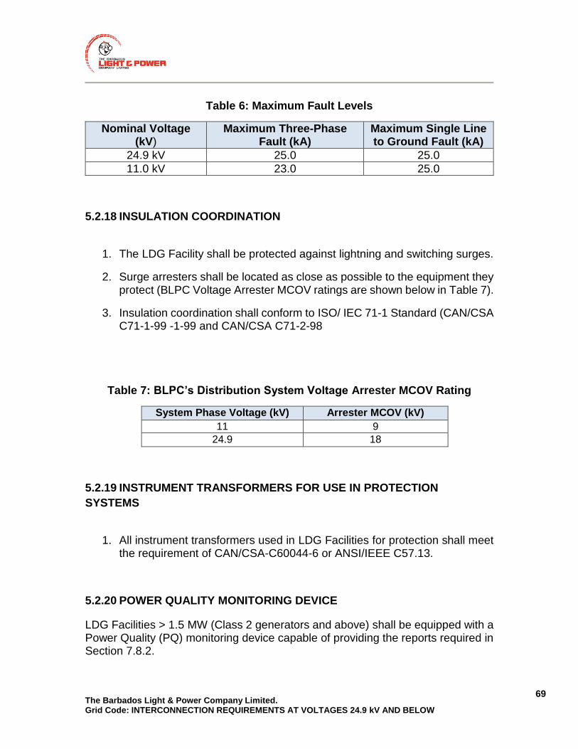
The Barbados Light & Power Company Limited. Grid Code: INTERCONNECTION REQUIREMENTS AT VOLTAGES 24.9 kV AND BELOW
69
Table 6: Maximum Fault Levels
Nominal Voltage (kV)
Maximum Three-Phase Fault (kA)
Maximum Single Line to Ground Fault (kA)
24.9 kV 25.0 25.0
11.0 kV 23.0 25.0
5.2.18 INSULATION COORDINATION
1. The LDG Facility shall be protected against lightning and switching surges.
2. Surge arresters shall be located as close as possible to the equipment they protect (BLPC Voltage Arrester MCOV ratings are shown below in Table 7).
3. Insulation coordination shall conform to ISO/ IEC 71-1 Standard (CAN/CSA C71-1-99 -1-99 and CAN/CSA C71-2-98
Table 7: BLPC’s Distribution System Voltage Arrester MCOV Rating
System Phase Voltage (kV) Arrester MCOV (kV)
11 9
24.9 18
5.2.19 INSTRUMENT TRANSFORMERS FOR USE IN PROTECTION
SYSTEMS
1. All instrument transformers used in LDG Facilities for protection shall meet
the requirement of CAN/CSA-C60044-6 or ANSI/IEEE C57.13.
5.2.20 POWER QUALITY MONITORING DEVICE
LDG Facilities > 1.5 MW (Class 2 generators and above) shall be equipped with a Power Quality (PQ) monitoring device capable of providing the reports required in Section 7.8.2.

The Barbados Light & Power Company Limited. Grid Code: INTERCONNECTION REQUIREMENTS AT VOLTAGES 24.9 kV AND BELOW
70
1. The PQ monitoring device shall have the ability to perform sampling at the rate of 256 samples / cycle (~15kHz) for a minimum of 96 cycles. This will ensure that the device is capable of recording voltage and current harmonics up to the 50th harmonic (3kHz), impulsive transients in the milliseconds range (monitoring possible to at most 7kHz), and low frequency oscillatory transients (<5kHz).
2. The instrument transformers used for PQ monitoring shall be capable of
monitoring transients up to 7 kHz, and swells up to 1.2 p.u. for a period of one minute.
3. PQ monitoring applies to phase voltages, neutral to ground voltage and phase currents.
5.2.21 PROTECTION FROM ELECTROMAGNETIC INTERFERENCE (EMI)
1. EMI shall not cause the protection, control and communication functions of
the LDG Facility interconnection to fail, change state, misoperate or provide inaccurate information.
2. The LDG Facility interconnection must have the capability to withstand electromagnetic interference (EMI) environments in accordance with:
a) ANSI/IEEE Std. C37.90.2 ― IEEE Standard for Withstand Capability of Relay Systems to Radiated Electromagnetic Interference from Transceivers.; or
b) CAN/CSA-CEI/IEC 61000-4-3 (Electromagnetic compatibility – testing and measurement techniques), using Level X, 35 V/m, in accordance with IEEE C37.90.2.
3. The LDG Owner shall provide documentation to show compliance with Item (2)(a) or (2)(b) above.
5.2.22 SURGE WITHSTAND
1. The protection, control and communication equipment of the LDG Facility interconnection system shall not within reason fail, misoperate, or provide misinformation due to voltage or current surges.
2. The interconnection system shall have the capability to withstand voltage and current surges in accordance with the environments defined in IEC

The Barbados Light & Power Company Limited. Grid Code: INTERCONNECTION REQUIREMENTS AT VOLTAGES 24.9 kV AND BELOW
71
61000-4-5 Electromagnetic Compatibility, Testing and measurement techniques–Surge immunity test.
5.2.23 SIMULATION MODELS
1. For LDG of Class 2 and above, the LDG Owner shall submit to BLPC a time-domain computer simulation model representing the dynamic behaviour of the LDG Facility.
2. The simulation model shall be in a file format that can be imported by the power system simulation software ETAP (or any other software currently in use by BLPC), in the version of ETAP currently used by BLPC. The version number of ETAP is available from BLPC on request.
3. The dynamic model shall implement steady-state limits, transient behaviour during under-frequency and over-frequency events, and transient behaviour during over-voltage and under-voltage events.
4. The model shall be of RMS type (for electromechanical rather than electromagnetic transients) and work with simulation time steps between 0.1 milliseconds and 10 milliseconds.
5. The model may or may not be encrypted.
6. Documentation describing the details of model usage and the implemented functions shall be provided.
7. Model and documentation shall be updated in case relevant modifications are made to the installed LDG Facility.
5.2.24 GENERATORS PARALLELING FOR 5 CYCLES OR LESS (CLOSED
TRANSITION SWITCHING)
1. The generators paralleling for 5 cycles or less shall be exempt from all requirements in this document except for the requirements below in Item (2) and Item (3).
2. LDG Facilities paralleling for 5 cycles or less shall have the following protection:
a) Under-voltage protection to ensure that the generator is not capable of energizing BLPC’s Transmission or Distribution System if it is de-energized and

The Barbados Light & Power Company Limited. Grid Code: INTERCONNECTION REQUIREMENTS AT VOLTAGES 24.9 kV AND BELOW
72
b) A 6-cycle timer to ensure that the LDG Facility will not parallel with BLPC’s Transmission and Distribution System for more than 6 cycles.
3. Synchronization facilities, where required, must follow the requirements specified in Section 5.5.4.
5.2.25 PROVISION FOR FUTURE CHANGES
1. The LDG Owner shall be responsible to stay aware of future changes to the
business environment and technical requirements.
2. The LDG Owner shall make any necessary changes to the LDG Facility promptly in response to:
a) New or revised standards;
b) New or revised codes;
c) Legislation changes;
d) Safety concerns and
e) BLPC requirements
3. The LDG Owner may be responsible for some or all costs associated with the changes in Item (2).

The Barbados Light & Power Company Limited. Grid Code: INTERCONNECTION REQUIREMENTS AT VOLTAGES 24.9 kV AND BELOW
73
5.3 PERFORMANCE REQUIREMENTS
5.3.1 GENERAL
1. The interconnection of the LDG Facility must not materially compromise the
reliability or restrict the operation of BLPC’s Distribution System.
2. The interconnection must not degrade power quality below acceptable levels listed in Section 5.3.2 (Power Quality Requirements).
3. The LDG Owner shall ensure that the facility is equipped to measure, record and report on performance related events to demonstrate compliance with the applicable sections of this document.
4. If the LDG Facility is found to significantly deteriorate the performance of the BLPC’s Transmission and Distribution System, it shall be disconnected from BLPC’s Distribution System until appropriate measures are taken to mitigate the negative impacts.
5.3.2 POWER QUALITY
5.3.2.1 VOLTAGE
1. The LDG Facility shall ensure that the operation of the LDG(s) does(do) not
have an objectionable impact on voltage at the PCC or the interconnected feeder and shall not cause any violation of IEEE Standard 1547, CSA Standard C235-83-CAN3 - Preferred Voltage Levels for AC Systems, 0 to 24,900 V Electric Power Transmission and Distribution along the entire interconnected feeder.
2. PCC voltage shall be maintained within 0.94~1.06 p.u. and shall not be lower than pre-connection voltage.
3. The LDG shall not actively regulate the voltage at the PCC unless agreed with BLPC. Voltage at the PCC shall be maintained within acceptable limits by following the requirements in item (8).

The Barbados Light & Power Company Limited. Grid Code: INTERCONNECTION REQUIREMENTS AT VOLTAGES 24.9 kV AND BELOW
74
4. Voltage variations at the PCC shall be limited in accordance with the ―Voltage Fluctuations (Flicker) Requirements in Section 5.3.2.3.
5. At the feeder level, LDG shall not contribute to short-term voltage fluctuation
anywhere on the feeder by more than 1%.
6. At the station level, all LDGs connected to the Distribution System shall not collectively contribute to short-term voltage fluctuation at the station LV bus by more than 3%.
7. Tripping of all LDGs connected to the station shall not cause abrupt voltage change to result in a voltage above 110% of nominal bus voltage, or less than 90% of nominal bus voltage, after a single contingency and before the station OLTC/feeder VR operates.
8. The reactive power provision of the LDG Facility at the PCC shall be as required in Section 5.3.3.
9. During normal operation, the LDG shall be loaded and unloaded gradually to allow adequate time for regulating devices on BLPC’s Transmission and Distribution System to respond and avoid excessive voltage fluctuations. Refer to Sections 5.3.7.11 and 5.4.13(4,5,6, and 7) for specific information.
10. The LDG Facility shall protect itself from abnormal voltage conditions which the distribution system is subjected to. These may include, but are not limited to:
a) Voltage transients and
b) Sags and swells caused by lightning, switching, faults, intermittent RE and the loss or switching of customer loads.
11. Insulation levels and protective equipment at the LDG Facility shall be capable of withstanding abnormal voltages from BLPC’s Transmission and Distribution System.
5.3.2.2 VOLTAGE AND CURRENT UNBALANCE
1. The LDG Facility shall be capable of operating under existing unbalance
conditions.
2. The LDG Facility shall not cause deterioration of existing imbalance voltage and current conditions at the PCC and in the Distribution System.

The Barbados Light & Power Company Limited. Grid Code: INTERCONNECTION REQUIREMENTS AT VOLTAGES 24.9 kV AND BELOW
75
3. A single-phase generator shall not negatively impact the unbalance of the nearest three-phase section of the Distribution System.
4. The LDG and its interconnection transformer‘s design shall take into consideration the unbalanced current it may supply to the unbalanced load on the feeder.
5. Single-phase generators shall not cause a steady-state voltage unbalance of greater than 3% when connected alone.
6. If multiple single-phase generators are installed, they shall be connected so that an equal amount of generation is applied to each single phase of the distribution line, and this balance shall be maintained if one or more of the generating units go offline.
5.3.2.3 VOLTAGE FLUCTUATIONS (FLICKER)
1. The LDG Facility shall not create objectionable flicker for other customers
on BLPC’s Distribution System.
2. The voltage dip at the PCC should not be more than 3% on connecting the single largest generation unit in the facility and should remain within 10% of nominal voltage when the entire LDG Facility and all other LDG Facilities on the interconnected feeder trip. These limits may be relaxed following the CIA-L process.
3. Item (1) above, shall include flicker caused by energization inrush.
4. The LDG Owner shall take steps to make sure that flicker requirements in Item (1) and (2) are met. For example by adding loss of synchronism protection, stagger generator energization, etc.
5. The LDG Facility shall conform to the flicker requirements in CAN/CSA-CEI/IECC61000-3-7 and meet the Pst and Plt limits shown below in Table 8.
Table 8: Pst and Plt Flicker Limits 11-24.9 kV
Pst 0.9
Plt 0.7
6. Flicker measurements shall be conducted by the LDG Owner using a device
that conforms to IEEE Standard 1547, CAN/CSA-CEI/IEC C61000-4-15 if

The Barbados Light & Power Company Limited. Grid Code: INTERCONNECTION REQUIREMENTS AT VOLTAGES 24.9 kV AND BELOW
76
requested by BLPC. BLPC shall request this measurement if flicker complaints are received in the surrounding area.
7. Induction generators and inverter-based generators that do not produce fundamental voltage before the paralleling device is closed, and double-fed generators whose excitation is precisely controlled by power electronics to produce a voltage with magnitude, phase angle, and frequency that match those of the Distribution System shall be tested to determine the maximum start-up current. The results shall be used, along with the Distribution System source impedance for the proposed location, to estimate the starting voltage magnitude change and verify that the unit will not cause a voltage fluctuation at the PCC greater than ± 4% of the prevailing voltage level of the Distribution System at the PCC.
8. Induction generators may be connected and brought up to synchronous speed by direct application of rated voltage provided that they meet the requirement of voltage drop given above and/or they do not exceed flicker limits at the PCC. Otherwise, other methods such as reduced voltage starting or speed matching, using the prime mover prior to connection, must be used to respect these voltage drop and flicker limits.
9. Large LDG Facilities, with multiple generator units, shall stagger the generator reconnections to BLPC’s Distribution System to meet the above requirements.
5.3.2.4 VOLTAGE AND CURRENT HARMONICS
1. The LDG Facility shall not inject harmonic current that causes unacceptable
voltage distortion on BLPC’s Transmission and Distribution System.
2. The LDG Facility shall follow the requirements of IEEE Standard 519 and CAN/CSA -CEI/IEC C61000-3-06.
3. The LDG Facility shall operate within the voltage distortion limits as indicated in Table 9 and Table 10 below.

The Barbados Light & Power Company Limited. Grid Code: INTERCONNECTION REQUIREMENTS AT VOLTAGES 24.9 kV AND BELOW
77
Table 9: Voltage Distortion limits for Odd Harmonics
Odd Harmonics Non Multiples of 3 Odd Harmonics Multiples of 3
Harmonic Voltage (%) Harmonic Voltage (%)
11-24.9 kV 11-24.9 kV
5 5 3 4
7 4 9 12
11 3 15 0.3
13 2.5 21 0.2
17 1.6 >21 0.2
19 1.2
23 1.2
25 1.2
>25 0.2+0.5(25/h)
Table 10: Voltage Distortion limits for Even Harmonics Even Harmonics
Even Harmonics
Harmonic Voltage (%)
11-24.9 kV
2 1.6
4 1
6 0.5
8 0.4
10 0.4
12 0.2
>12 0.2
4. Total Harmonic Distortion (THD) shall be a maximum of 5% on 24.9 kV systems and below 5.0% on all other systems.
5. The LDG Facility shall operate within the current harmonic limits as listed in Table 11.
Table 11: Harmonic Current Limits
Harmonic Number h 5 7 11 13
Admissible harmonic current ih=Ihi/Ii (%)
5-6 3-4 1.5-3 1-2.5

The Barbados Light & Power Company Limited. Grid Code: INTERCONNECTION REQUIREMENTS AT VOLTAGES 24.9 kV AND BELOW
78
6. The LDG Owner and/or BLPC may be required to implement measures that will mitigate the harmonic distortion caused by the LDG Facility, such as by adding harmonic filters, at the LDG Owners cost.
7. The limits presented in Items (3), (4) and (5) above exclude the harmonic distortion present on BLPC’s Transmission and Distribution System when the LDG Facility is disconnected from the Transmission and Distribution System.
8. This document does not impose design limits to limit harmonic-related
telephone interference problems as it is almost impossible to predict. However, the LDG Owner shall make sure that the design complies with all applicable standards and shall not cause telephone interference.
5.3.2.5 FREQUENCY
1. The generators at the LDG Facility shall operate at a nominal frequency
of 50Hz.
2. The generators at the LDG Facility shall remain synchronously connected over the frequency range presented in Section 5.3.8 in Table 13.
3. The generators shall trip in the time required in accordance with Section 5.4.9 for any frequencies beyond what is presented in Section 5.3.8 in Table 13.
5.3.2.6 LIMITATION OF DC INJECTION
1. The DC current injection by the LDG Facility shall not be greater than 0.5%
of the full rated output current at the PCC after a period of five cycles following the energization of BLPC’s Distribution System.
5.3.3 REACTIVE POWER AND VOLTAGE CONTROL
1. LDG Facilities > 150 kW shall be capable of operating with a power factor
anywhere between 0.95 leading and 0.95 lagging, as measured at the PCC.
The Barbados Light & Power Company Limited. Grid Code: INTERCONNECTION REQUIREMENTS AT VOLTAGES 24.9 kV AND BELOW
79
2. If warranted by local distribution system conditions, this range may be narrower or wider and will be specified by BLPC in the CIA-L.
3. The LDG Facility shall be capable of operating within lagging and leading
power factor ranges with, or without, other LDG Facilities in service on the feeder.
4. The LDG Facility shall be capable of providing reactive power according to any of the following four reactive power control schemes: a) At a fixed power factor 0.95 lagging ≤ cos φ ≤ 0.95 leading; b) At a power factor dependent on the active power feed-in cos φ (P); c) At a fixed level of reactive power in MVar; d) At a level of reactive power dependent on the voltage Q(U).
5. BLPC shall determine the required reactive power control scheme of the LDG Facility during the CIA-L study and shall specify this to the LDG Owner.
6. Upon request by BLPC, the reactive power control scheme of the LDG Facility shall be adjusted within one month if deemed necessary by BLPC.
7. Power factor correction or reactive power compensation techniques may be required, if determined by BLPC in the CIA-L.
8. Induction generators consume reactive power and the LDG Owner shall be required to provide reactive power compensation to correct the power factor at the PCC, if determined by BLPC in the CIA-L.
9. LDG Facilities greater than 10 MW (Class 3 LDGs) shall be assessed by BLPC to determine whether the proposed generation impacts the main transmission negatively and whether the reactive power compensation at the generator units shall be sufficient, so as not to cause any material increase in the reactive power requirements at the transmission system transformer station due to the operation of the LDGs at all load conditions on the feeder. This assessment shall be made during the CIA-L.
5.3.4 DISTURBANCES
1. The LDG Facility shall be designed, built and maintained in accordance with
all applicable codes, regulations and standards, along with the requirements of this document. The design shall minimize the impact of:
a) Over-voltages during ground faults;
b) Electric disturbances which can cause irregular power flows;
The Barbados Light & Power Company Limited. Grid Code: INTERCONNECTION REQUIREMENTS AT VOLTAGES 24.9 kV AND BELOW
80
c) Interference – radio, television and telephone;
d) Audible noise and
e) Other disturbances which may reduce the reliability of BLPC’s distribution system.
5.3.5 RESONANCE ANALYSIS
1. The prudent design of a LDG Facility should include careful consideration
of resonance and ferroresonance.
2. Ferroresonance or resonance studies are not mandatory.
3. If resonance problems do arise, full co-operation and data sharing on the part of the LDG Owner shall be required.
5.3.6 SELF-EXCITATION ANALYSIS
1. LDG Facilities with induction generators and not equipped with Transfer
Trip, (Section 5.4.14), shall conduct studies to assess whether there is a possibility of self-excitation.
2. Self-excitation analysis, if required by item (1) above, shall be submitted to BLPC for review.
5.3.7 UNDER-VOLTAGE AND OVER-VOLTAGE RIDE THROUGH
1. The LDG Facility interconnection protection scheme shall have the capability of detecting abnormal voltages.
2. Three phase inverter systems shall detect each individual phase to neutral voltage on a grounded Wye system or each individual phase to phase voltage on an ungrounded Wye or delta system.
3. Single phase inverter systems shall detect the phase to neutral voltage if connected to the neutral conductor.

The Barbados Light & Power Company Limited. Grid Code: INTERCONNECTION REQUIREMENTS AT VOLTAGES 24.9 kV AND BELOW
81
4. Single phase inverter systems connected phase to phase (not connected to the neutral conductor) shall detect the phase to phase voltage.
5. The voltages shall be detected at the PCC. LDGs up to 500kW may be exempt from this clause subject to the CIA review as explained in Clause 6 below.
6. If the requirement in Item (5) above is not practical or feasible, estimated values may be used, if approved by BLPC.
7. In the case of under-voltage for synchronous generators, the LDG Facility shall not disconnect from the grid if the voltage as a percentage of the nominal voltage value remains above the lower blue line in Figure 9 (in the case of three-phase generators, the voltage refers to the smallest line-to-neutral or line-to-line voltage at the generator terminal); the points which define the lower blue line in Figure 9 are listed in Table 12.
8. In the case of under-voltage for non-synchronous generators, the LDG Facility shall not disconnect from the grid if the voltage as a percentage of the nominal voltage value remains above the lower blue line in Figure 10 (in the case of three-phase generators, the voltage refers to the smallest line-to-neutral or line-to-line voltage at the generator terminal); the points which define the lower blue line in Figure 10 are listed in Table 12.
9. In Figure 9 and Figure 10 the time t=0 seconds marks the beginning of the voltage drop (where the voltage first falls below 90% of the nominal voltage).
10. In the case of over-voltage, the LDG Facility shall not disconnect for 0.92 s if the voltage rises to between 110% and 120% of its nominal value. This is illustrated by the upper blue line in Figure 9 and Figure 10.
11. If the active power production is reduced during the fault, it shall be ramped up back to the pre-fault value after fault clearance with a ramp rate of at least 10% of the rated power per second.

The Barbados Light & Power Company Limited. Grid Code: INTERCONNECTION REQUIREMENTS AT VOLTAGES 24.9 kV AND BELOW
82
Figure 9 (illustrative): Voltage Ride Through curves for synchronous
generators > 150 kW, and trip curves according to section 5.4.10.
Figure 10 (illustrative): Voltage Ride Through curve for non-synchronous
generators > 150 kW, and trip curves according to section 5.4.10.
0
20
40
60
80
100
120
140
-500 0 500 1000 1500 2000 2500 3000 3500
Vo
ltag
e in
pe
r ce
nt
(%)
Time in milliseconds
Voltage Ride Through
Trip
must not disconnect
may disconnect
must disconnect
must disconnect
0
20
40
60
80
100
120
140
-500 0 500 1000 1500 2000 2500 3000 3500
Vo
ltag
e in
pe
r ce
nt
(%)
Time in milliseconds
Voltage Ride Through
Tripmust not disconnect
may disconnect
must disconnect
must disconnect

The Barbados Light & Power Company Limited. Grid Code: INTERCONNECTION REQUIREMENTS AT VOLTAGES 24.9 kV AND BELOW
83
Table 12: Under-Voltage Ride Through curve point definitions for LDG
UVRT points for synchronous LDG UVRT points for non-synchronous LDG
Time (milliseconds)
Voltage (%) Time (milliseconds)
Voltage (%)
0 0 0 0
200 0 1000 0
200 15 1000 48
600 15 1500 90
1500 90
5.3.8 UNDER-FREQUENCY AND OVER-FREQUENCY RIDE THROUGH
1. The LDG Facility interconnection protection scheme shall have the capability of detecting abnormal frequencies shown below in Table 13.
2. The LDG Facility shall not disconnect during abnormal frequencies within the ranges and within the time limits marked “Ride Through” in Table 13. The same conditions are illustrated in Figure 11.
3. The times in Table 13 shall be measured from the instant when the measured frequency has crossed the respective threshold.

The Barbados Light & Power Company Limited. Grid Code: INTERCONNECTION REQUIREMENTS AT VOLTAGES 24.9 kV AND BELOW
84
Figure 11 (illustrative): Illustration of Frequency Operating Limits for LDG
> 150 kW (informative)
Table 13: LDG > 150 kW Frequency Operating Limits
Range (Hz) Mode FRT Duration (s)
Ride Through
Trip
f > 53.0 Trip None 0.20
52.5 < f ≤ 53.0 Ride Through 20 21
47.5 < f ≤ 52.5 Normal Operation Indefinite Indefinite
47.0 ≤ f ≤ 47.5 Ride Through 20 21
f < 47.0 Trip None 0.20
5.3.9 FREQUENCY DROOP FOR SYNCHRONOUS GENERATORS
1. All synchronous LDG Facilities shall be capable of operating in droop frequency control mode according to a fixed frequency droop parameter between 3% and 10%.
2. BLPC will specify the droop parameter in the CIA-L.
0,1
1
10
100
1000
45 46 47 48 49 50 51 52 53 54 55
Tim
e in
se
con
ds
Frequency in Hz
Frequency Ride Through
Trip
must not disconnect
may disconnect
must disconnect
may disconnect
must disconnect

The Barbados Light & Power Company Limited. Grid Code: INTERCONNECTION REQUIREMENTS AT VOLTAGES 24.9 kV AND BELOW
85
5.3.10 OVER-FREQUENCY ACTIVE POWER REDUCTION FOR NON-
SYNCHRONOUS GENERATORS
1. All non-synchronous LDG Facilities shall reduce their active power output by a frequency-dependent power difference ΔP when the system frequency exceeds a threshold of 51.0 Hz.
2. The active power output at the time when the frequency crosses the threshold is frozen and taken as the reference PM for the power reduction.
3. Above the threshold, the power reduction per unit of PM is calculated according to the formula: ΔP/ PM (per unit) = 20 × (51.0 Hz – fsystem)/50 Hz where fsystem is the system frequency in Hz.
4. This corresponds to a power reduction of 40% of the frozen reference active power per Hz.
5. The frequency measurement shall be accurate within 10 mHz. The response time to over-frequency shall be as fast as possible, and not larger than 0.5 seconds.
6. When the system frequency returns to below 51.0 Hz and the LDG Facility is then capable of producing more than the previously frozen reference active power, the active power may be ramped up to the maximum with a ramp rate not exceeding 10% of the rated active power output per minute.
7. LDG Facilities not capable of adjusting their active power output shall disconnect at a randomized frequency threshold between 51.0 Hz and 53.0 Hz. The randomization may be performed by the manufacturer, such that a fixed threshold may be built into the generation units.
fsystem
ΔP
51.0 Hz 50 Hz

The Barbados Light & Power Company Limited. Grid Code: INTERCONNECTION REQUIREMENTS AT VOLTAGES 24.9 kV AND BELOW
86
5.4 PROTECTION REQUIREMENTS
5.4.1 GENERAL REQUIREMENTS
1. All protective device settings and protection scheme designs must be
submitted to BLPC for review.
2. Protections must not be interlocked with the position of any isolating/interrupting devices.
3. Protection settings may be required to be changed over time to maintain adequate system protection as the system configuration changes.
4. All protection operations shall ensure that the generator(s) and all HV Ground Sources are isolated from BLPC’s Transmission and Distribution System within the required time from the start of the disturbance.
5. All protection designs must:
a) Ensure proper coordination with BLPC’s protections;
b) Be failsafe; and
c) Ensure that both the LDG and BLPC’s distribution system, customers and general public safety are maintained.
6. For Class 2 LDGS and above the design of the protections at the LDG Facility shall be done by a registered engineer to ensure that the overall protection scheme will ensure a safe and reliable interconnection to BLPC’s Transmission and Distribution System.
7. For Class 2 LDGS and above protection relays shall be “utility grade” and shall meet the minimum requirements specified in IEEE C37.90, “Standard for Relays and Relay Systems Associated with Electrical Power Apparatus,” latest edition, as well as meet the requirements in Section 5.2.21 and Section 5.2.22. “Industrial grade” relays shall not be permitted for interconnection protections.
8. Protection functions shall remain operational after distribution system disturbances or loss of supply from the distribution system for the required period of time needed to operate properly.
9. For Class 2 LDGS and above communication facilities between the TS and breaker and the LDG Facility may be required as a result of LDG Facility interconnections.
The Barbados Light & Power Company Limited. Grid Code: INTERCONNECTION REQUIREMENTS AT VOLTAGES 24.9 kV AND BELOW
87
10. For Class 2 LDGS and above the interconnection protection is required to
have a dedicated device but if the LDG Owner decides to combine some of the protection functions in other relays, this would be subject to BLPC’s approval.
11. Additional protections, other than the ones listed in this document, may be required depending on the application and shall be communicated to the LDG Owner at the appropriate stage.
5.4.2 SENSITIVITY AND COORDINATION
1. The LDG Facilities protection shall provide adequate sensitivity to detect
abnormal conditions as required in Section 5.4 and isolate its generator(s) and if present, its HV ground fault source from BLPC’s Transmission and Distribution System.
2. The design of the LDG Facility protection system shall coordinate with other BLPC protection system devices.
5.4.3 PROTECTION OPERATING TIMES
1. The LDG Facility‘s interconnection protection shall disconnect the LDG
Facility`s generation and, if present, its HV ground fault sources from BLPC’s Transmission and Distribution System within the required time as specified in the individual requirements throughout this document.
5.4.4 BREAKER FAIL (BF)
1. LDG Facilities of Class 2 and above shall provide breaker failure protection
for the primary interrupting device (i.e. breaker, HVI, LVI) that is responsible for disconnecting the generation and/or HV ground sources from BLPC’s Transmission and Distribution System.
2. The breaker failure protection should have a maximum pickup time delay of 0.3s after initiation.
3. In the event of a HVI breaker fail condition, the breaker fail protection shall:
The Barbados Light & Power Company Limited. Grid Code: INTERCONNECTION REQUIREMENTS AT VOLTAGES 24.9 kV AND BELOW
88
a) Trip the next zone at the LDG facility, specifically the upstream isolation device and all LV breakers shall be tripped and
b) Remove the prime mover and excitation system as appropriate.
4. In the event of a LVI breaker fail condition, the breaker fail protection shall ensure that a fault in the LDG Facility is cleared and will not affect the Distribution System by:
a) Tripping the HVI;
b) Initiating Breaker Fail on the HVI;
c) Opening the motorized disconnect switch (Isolation Device) as explained in Item (6) below and .
d) Removing the prime mover and excitation system as appropriate.
5. The motorized disconnect switch (see requirements in Section 5.2.7 (3)(b) shall be opened by a separate auxiliary relay in the event of a breaker fail condition to ensure that the LDG Facility is properly isolated from BLPC’s Transmission and Distribution System.
6. The motorized disconnect switch shall be used to automatically isolate the LDG Facility from the Transmission and Distribution System. In the event that an alternate interrupting means (fuses or otherwise) is not provided by the LDG Facility, or if such alternate interrupting means fail to coordinate with the opening of the motorized disconnect switch, then the disconnect switch may incur significant damage when attempting to interrupt a sustained fault current condition as it is not rated for breaking fault current. The design of the LDG Facility shall take this into consideration when deciding on a location for the Isolation Device to ensure that safety of the LDG Facility personnel, BLPC’s personnel and general public will be ensured.
7. In the case of a circuit switcher being used, the interrupter and the motorized disconnect shall be specifically chosen to operate independently and no additional BF protection shall be required. If the motorized disconnect switch in the circuit switcher is not rated to break load, an additional load break switch shall be required to satisfy the requirement in Section 5.2.7.
8. The design of the BF protection for the HVI shall be submitted to BLPC for review and acceptance.
The Barbados Light & Power Company Limited. Grid Code: INTERCONNECTION REQUIREMENTS AT VOLTAGES 24.9 kV AND BELOW
89
DESIGN CONSIDERATION In normal operation, when the HVI isolates the facility, the motorized disconnect switch will follow, opening a short period afterwards. It can also be designed to open sequentially – motorized disconnect opens if HVI does not OPEN following a trip initiation.
5.4.5 THREE-PHASE GENERATORS
1. Three-Phase LDG Facilities shall have the minimum protection
requirements as shown below in Table 14 and are mandatory for all generators to which this Grid Code document is applicable.
2. Inverter type generators shall be compliant with IEEE Standard 1547 or CAN/CSA 22.2 No 257-06 “Interconnecting inverter based micro distributed resources to distribution system” , CSA Standards, C 22.2-107.1 “General use Power Supply” or UL 1741 and VDE0126 and VDE AR-N4105 for connections at LV and MV or any other codes that include VRT/FRT requirements. Inverter generators shall bear a certification mark recognized in Barbados.
3. The final design of the protection system shall be submitted to BLPC for approval in accordance with Section 5.4.20 of this document.

The Barbados Light & Power Company Limited. Grid Code: INTERCONNECTION REQUIREMENTS AT VOLTAGES 24.9 kV AND BELOW
90
Table 14: Minimum Protections Required for Three-Phase LDG Facilities
F u n c t i o n R e q u i r e m e n t
Protection Element function
Device #
Synchronous Induction Inverter
Basic Anti-Islanding
Over voltage trip 59 Required Required Required
Under voltage trip 27 Required Required Required
Over frequency trip
81O Required Required Required
Under frequency 81U Required Required Required
Tele-protections
Transfer trip received
TTR Section 5.4.14 Section 5.4.14
Section 5.4.14
DGEO/LSBS DGEO Section 5.4.15 Section 5.4.15
Section 5.4.15
F u n c t i o n R e q u i r e m e n t
Protection Element function
Device #
Synchronous Induction Inverter
Other passive Anti-islanding
Rate of change of frequency
81R < 1500 kW < 1500 kW Not
required
Vector Surge 78 < 1500 kW < 1500 kW Not
required
Directional Reactive Power
Relay 32R < 1500 kW < 1500 kW
Not Required
Phase Fault Protection
Phase Overcurrent
50 Required Required Required
Phase inverse timed
Overcurrent 51 See note 12 See note 1
See note 1
Voltage Controlled
Overcurrent 51V See note1 See note1
See note 1
Directional Phase Overcurrent
67 Required Required Required
2 An alternative or complement to Over-current (50, 50N). Special caution is needed for selection of inverse-time characteristics that meet time constraints

The Barbados Light & Power Company Limited. Grid Code: INTERCONNECTION REQUIREMENTS AT VOLTAGES 24.9 kV AND BELOW
91
Figure 12 (illustrative): 4-Wire DGIT Option #1 Typical Protection

The Barbados Light & Power Company Limited. Grid Code: INTERCONNECTION REQUIREMENTS AT VOLTAGES 24.9 kV AND BELOW
92
Figure 13 (illustrative): 4-Wire DGIT Option #2 Typical Protection
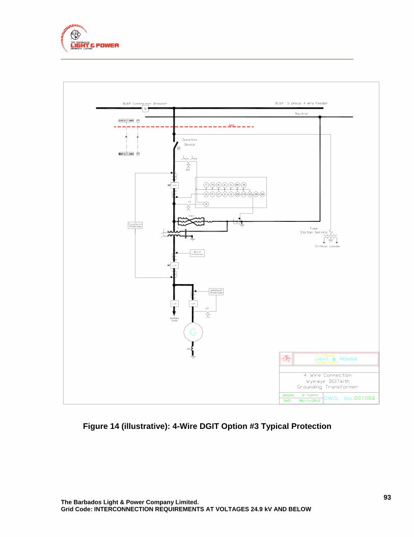
The Barbados Light & Power Company Limited. Grid Code: INTERCONNECTION REQUIREMENTS AT VOLTAGES 24.9 kV AND BELOW
93
Figure 14 (illustrative): 4-Wire DGIT Option #3 Typical Protection

The Barbados Light & Power Company Limited. Grid Code: INTERCONNECTION REQUIREMENTS AT VOLTAGES 24.9 kV AND BELOW
94
Figure 15 (illustrative): 4-Wire DGIT Option #4 Typical Protection

The Barbados Light & Power Company Limited. Grid Code: INTERCONNECTION REQUIREMENTS AT VOLTAGES 24.9 kV AND BELOW
95
Figure 16 (illustrative): 4-Wire DGIT Option #5 Typical Protection

The Barbados Light & Power Company Limited. Grid Code: INTERCONNECTION REQUIREMENTS AT VOLTAGES 24.9 kV AND BELOW
96
5.4.6 PHASE AND GROUND FAULT PROTECTION
1. The LDG Facility‘s protection system shall ensure that the LDG Facility will
detect and isolate itself and any HV ground sources from BLPC’s Transmission and Distribution System for:
a) All internal faults within the LDG Facility
b) All external faults on the interconnected BLPC Distribution Feeder including single phase lateral spurs. This applies to all phase-phase and phase-ground faults and should be coordinated with BLPCs protection devices.
2. Phase and ground protection shall always be operational whenever phase and ground current can be sourced from the LDG Facility.
3. The protective device selectivity and sensitivity shall be maintained over the full range of minimum to maximum fault currents (present and anticipated future levels) with the LDG’s infeed.
4. The LDG Facility shall be capable of selectively detecting faults on the LDG side of the HVI, and shall disable the HVI auto-reclosure scheme – (Refer to Section 5.4.12).
5. The total clearing time for faults on BLPC’s Transmission and Distribution System or for faults in the LDG Facility shall be no more than:
a) 500 ms for LDG Facilities equipped with fast Transfer Trip (for LDGs of Class 2 and above); or
b) 200 ms for LDG Facilities not equipped with fast Transfer Trip. This can be relaxed to 500 ms if the LDG Owner can demonstrate that the LDG Facility fault contributions will not encroach on BLPC’s Distribution System minimum fuse melt characteristic.
[Note: The total clearing time is measured from the start of the abnormal condition to the time that the LDG Facility ceases to energize BLPC’s Distribution System].

The Barbados Light & Power Company Limited. Grid Code: INTERCONNECTION REQUIREMENTS AT VOLTAGES 24.9 kV AND BELOW
97
5.4.7 OPEN PHASE PROTECTION
1. The LDG Facility‘s protections must be capable of detecting the loss of any
phase to which the LDG Facility is connected which occurs within the LDG Facility or the Transmission and Distribution System.
2. Upon the detection of the open-phase condition, the LDG protection shall:
a) Disconnect the LDG from the Distribution System within 900ms and
b) Disconnect the DGIT from the Distribution System via a HVI or a HV Motorized Disconnect Switch whenever the DGIT is three-phase with a common (shared) magnetic core (for LDGs of Class 2 and above).
5.4.8 FEEDER RELAY DIRECTIONING (FOR LDGS OF CLASS 2 AND
ABOVE)
1. The protection relay looking towards BLPC’s feeder at the PCC may need
to be directional.
2. The need for Item (1) shall be specified to the LDG Owner following the CIA-L.
.
5.4.9 OVER FREQUENCY/UNDER FREQUENCY PROTECTION
1. The LDG Facility interconnection protection scheme shall have the capability of detecting abnormal frequencies shown in Table 13.
2. The LDG Facility shall disconnect from BLPC’s Transmission and Distribution System in the clearing times specified in Table 13 under “Trip”, but not before the Under- and Over-Frequency Ride Through times specified in Section 5.3.8.
3. The times in Table 13 shall be measured from the instant when the measured frequency has crossed the respective threshold.
The Barbados Light & Power Company Limited. Grid Code: INTERCONNECTION REQUIREMENTS AT VOLTAGES 24.9 kV AND BELOW
98
4. If the LDG has ceased to energize due to over/under frequency conditions, it shall reconnect only once the conditions in Section 5.4.11 or Section 5.4.12 are met.
5.4.10 OVERVOLTAGE/UNDERVOLTAGE PROTECTION
1. The LDG Facility interconnection protection scheme shall have the
capability of detecting abnormal voltages.
2. Three phase inverter systems shall detect each individual phase to neutral voltage on a grounded Wye system or each individual phase to phase voltage on an ungrounded Wye or delta system.
3. Single phase inverter systems shall detect the phase to neutral voltage if connected to the neutral conductor.
4. Single phase inverter systems connected phase to phase (not connected to the neutral conductor) shall detect the phase to phase voltage.
5. The voltages shall be detected at the PCC.
6. If the requirement in Item (5) above is not practical or feasible, estimated values may be used, if approved by BLPC.
7. The LDG Facility shall disconnect from BLPC’s Distribution System in the clearing times specified in Table 15, but not before the Under- and Over-Voltage Ride Through times specified in Section 5.3.7.
8. The clearing time in Table 15 shall be measured from the start of the abnormal condition until the time that the LDG Facility ceases to energize BLPC’s Distribution System.
9. More stringent clearing times may be specified in the CIA-L, if required.
10. High speed instantaneous voltage protection may be considered for detecting ferroresonance and self-excitation conditions.
11. The LDG Facility shall reconnect only once the conditions in Section 5.4.11 or Section 5.4.12 are met.
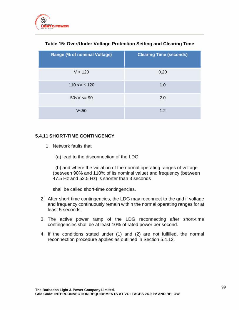
The Barbados Light & Power Company Limited. Grid Code: INTERCONNECTION REQUIREMENTS AT VOLTAGES 24.9 kV AND BELOW
99
Table 15: Over/Under Voltage Protection Setting and Clearing Time
Range (% of nominal Voltage) Clearing Time (seconds)
V > 120 0.20
110 <V ≤ 120 1.0
50<V <= 90 2.0
V<50 1.2
5.4.11 SHORT-TIME CONTINGENCY
1. Network faults that (a) lead to the disconnection of the LDG (b) and where the violation of the normal operating ranges of voltage (between 90% and 110% of its nominal value) and frequency (between 47.5 Hz and 52.5 Hz) is shorter than 3 seconds shall be called short-time contingencies.
2. After short-time contingencies, the LDG may reconnect to the grid if voltage and frequency continuously remain within the normal operating ranges for at least 5 seconds.
3. The active power ramp of the LDG reconnecting after short-time contingencies shall be at least 10% of rated power per second.
4. If the conditions stated under (1) and (2) are not fulfilled, the normal reconnection procedure applies as outlined in Section 5.4.12.
The Barbados Light & Power Company Limited. Grid Code: INTERCONNECTION REQUIREMENTS AT VOLTAGES 24.9 kV AND BELOW
100
5.4.12 RECONNECTION AFTER PROTECTION TRIPPING (FOR CLASS 2
AND ABOVE UNLESS OTHERWISE STATED)
1. LDG Facilities with aggregate size greater than 1.5 MW (Class 2 and above) shall not automatically reconnect to the network after protection tripping if there has been a total system shutdown.
2. A total system shutdown may be assumed to have occurred if the voltage of the feeder to which the LDG is connected remains absent for a continuous period of 15 minutes or more.
3. LDG Facilities of Class 2 and above may only reconnect to BLPC’s Transmission and Distribution System after a total system shutdown if permission is given by BLPC’s SCADA operators to reconnect.
4. If there has not been a total system shutdown or the LDG Facility has aggregate size less than 1.5 MW (Class 1), then the LDG may automatically reconnect to BLPC’s Distribution System if the conditions in (5), (6) and (7) are met.
5. After disconnection due to protection tripping, the LDG may reconnect to the grid when (a) the voltage continuously remains within 90% to 110% of its nominal value and, at the same time, (b) the frequency continuously remains between 47.5 Hz and 52.5 Hz for at least 60 seconds.
6. The active power ramp of the reconnected LDG shall not exceed 10% of rated power per minute until (a) the dispatched power output is reached (controllable LDG) (b) the momentary maximum power output or dispatched power output is reached (variable LDG)
7. If the active power ramp cannot be limited, reconnection shall be delayed by a random time (specific to each LDG unit) interval between 1 and 10 minutes.

The Barbados Light & Power Company Limited. Grid Code: INTERCONNECTION REQUIREMENTS AT VOLTAGES 24.9 kV AND BELOW
101
5.4.13 ANTI-ISLANDING PROTECTION (FOR CLASS 2 AND ABOVE UNLESS
OTHERWISE STATED)
1. Upon loss of voltage in one or more phases of BLPC’s Distribution System,
the LDG Facility shall automatically disconnect from BLPC’s Distribution System within 5 sec.
2. The LDG Owner shall demonstrate to BLPC that it shall not sustain an island for longer than the time requirements in Item (1) above.
3. All LDG Facilities shall have anti-islanding protection. This may involve different protection functions, however all LDG Facilities shall have:
a) Under/Over Frequency protection (Section 5.4.9);
b) Under/Over Voltage protection (Section 5.4.10); and
c) Transfer Trip for anti-islanding protection may be required as stipulated in Section 5.4.14.
4. LDG Facilities of Class 1 may be exempted from Item (3)(c), subject to item 8 below and allowed to install the following passive anti-islanding schemes, in lieu of Transfer Trip, as an interim protection until BLPC standardizes on a Transfer Trip solution for LDG Facilities of Class 1:
a) Rate of Change of Frequency (ROCOF) and
b) Vector Jump; or
c) Reverse Reactive Power.
5. The passive anti-islanding protection scheme in Item (4) shall be submitted to BLPC for approval.
6. The passive anti-islanding protections in Item (4) shall be set as sensitive as possible to reduce the non-detection zone and can be changed if it is found to cause unjustified nuisance trips. These settings changes shall have to be pre-approved by BLPC prior to implementation.
7. If BLPC does not find a suitable low cost solution to Transfer Trip, the interim passive anti-islanding protections in Item (4) shall be changed out to Transfer Trip.
8. The LDG Owner shall be aware and accept the consequences of utilizing passive anti-islanding schemes in Item (4) above as a primary anti-islanding
The Barbados Light & Power Company Limited. Grid Code: INTERCONNECTION REQUIREMENTS AT VOLTAGES 24.9 kV AND BELOW
102
protection and shall not hold BLPC responsible for any damage incurred due to islanded operation from events such as out-of-phase reclosing.
5.4.14 TRANSFER TRIP (TT) (LDG OF CLASS 2 AND ABOVE)
1. A TT signal from the station feeder breaker(s) to the LDG Facility shall be
required for all LDG Facilities of Class 2 and above.
2. A TT signal from the feeder breaker(s) and/or upstream recloser(s) (where the recloser is located between the LDG Facility and feeder breaker) to the LDG Facility shall be required for any or all of the following conditions:
a) When the aggregate LDG Facility capacity is greater than 50% of the minimum feeder load or the minimum load downstream of recloser(s); or
b) When the aggregate generation, comprising of existing generation, other earlier proposed LDG Facilities, and the concerned LDG Facility is greater than 50% of the minimum feeder load or minimum load downstream of the recloser; or
c) If the existing reclosing interval of the feeder breaker(s) and/or upstream recloser(s) is less than 1.0s.
3. A TT signal from upstream feeder breaker(s) and/or recloser(s) to the LDG Facility connected at downstream of Distribution substation (DS) supplied by that feeder shall be required. This is required when the aggregate generation, comprising of existing generation, other earlier proposed LDG Facilities at the feeder or at the DS, including concerned LDG Facility, is greater than 50% of minimum feeder load or the minimum load downstream of breaker/recloser respectively.
4. A TT signal from transmission line terminal breaker(s) of an upstream
Transformer substation (TS) to the LDG Facility shall also be required if the TS where the LDG Facility is being proposed is radially supplied by that transmission line and there is a possibility of islanding of the entire transmission line, or where Wide area islands could exist – aggregate generation on transmission line is greater than 50% of the minimum load on the transmission line. This signal will be cascaded onto the TT signal that will be required between the TS feeder breaker and the LDG Facility in Item (2) above.

The Barbados Light & Power Company Limited. Grid Code: INTERCONNECTION REQUIREMENTS AT VOLTAGES 24.9 kV AND BELOW
103
5. The LDG Facility shall cease to energize BLPC’s Transmission and Distribution System with no intentional time delay and isolate all generation and HV ground sources upon receipt of a Transfer Trip signal.
6. TT communications shall meet the timing requirements in Table 16. The
maximum TT time shall depend on the operational speed of the LDG Facilities interrupting device.
Table 16: TT Timing Requirements
Maximum TT Communication Time (ms)
Speed of LDG Facility`s Interrupting Device (cycles)
83 3
67 4
50 5
33 6
17 7
7. The LDG Facility shall remain disconnected from BLPC’s Transmission and
Distribution System if the TT channel is unavailable.
8. The TT teleprotection system shall be failsafe, and
9. Upon loss of the TT communication channel, the generation and HV ground sources shall disconnect within 5 seconds of the channel failing. A controlled shutdown may be allowed and must be submitted to BLPC for approval.
5.4.15 DISTRIBUTED GENERATOR END OPEN (DGEO) (LDG OF CLASS 2
AND ABOVE)
1. A Distributed Generator End Open (DGEO) real-time signal from the LDG
Facility to BLPC is required whenever Transfer Trip is required, as outlined in Section 5.4.14.
2. The DGEO and Low Set Block Signal (LSBS) (Refer to Section 5.4.16) signals shall be combined into one composite communications channel signal as outlined in the DGEO and LSBS Design Requirement in Section 5.4.17.

The Barbados Light & Power Company Limited. Grid Code: INTERCONNECTION REQUIREMENTS AT VOLTAGES 24.9 kV AND BELOW
104
3. Upon failure of the DGEO channel, BLPC may block its feeder reclosing until the channel is repaired.
4. The LDG Owner shall make repairs in the event of channel failure as quickly as possible.
5. In the event of Item (3) above, BLPC can seal in TT to the affected LDG Facility until the channel is repaired to enable automatic reclosing on its feeders.
5.4.16 LOW SET BLOCK SIGNAL (LSBS) (LDG OF CLASS 2 AND ABOVE)
1. A Low Set Block Signal (LSBS) from the LDG to the BLPC supply source
breaker or recloser, is required whenever TT is required, as outlined in Section 5.4.14.
2. The LSBS and DGEO (Refer to Section 5.4.15) signals shall be combined into one composite communications channel signal as outlined in the DGEO and LSBS Design Requirement in Section 5.4.17.
5.4.17 DGEO AND LSBS DESIGN (LDG OF CLASS 2 AND ABOVE)
1. The DGEO and LSBS (Refer to Section 5.4.15 and Section 5.4.16
respectively) signals shall be combined into one composite communications channel signal.
2. This dual function signal shall be set to one [1] when the breaker is open and set to zero [0] 1s prior to the energization of the DGITs.
5.4.18 SPECIAL INTERCONNECTION PROTECTION (LDG OF CLASS 2 AND
ABOVE)
1. Other protections not specified in this requirements document may be
required depending on the application.
2. The LDG Owner shall be aware of site specific conditions and the nature of BLPC’s Transmission and Distribution System to properly assess the need for additional protections.

The Barbados Light & Power Company Limited. Grid Code: INTERCONNECTION REQUIREMENTS AT VOLTAGES 24.9 kV AND BELOW
105
5.4.19 PROTECTION SCHEME FAILURES (LDG OF CLASS 2 AND ABOVE)
1. The LDG Facility generation and HV ground sources shall be disconnected from BLPC’s Transmission and Distribution System and notify BLPC’s system operators if:
a) The LDG local interconnection protection system fails; Interconnection protection systems provided by Independent Electronic Devices (IED) shall have self-diagnostic (control healthy) features that detect internal relay failures;
b) The breaker trip coil or interrupting device fails;
c) The DC supply is lost; or
d) The TT signal channel fails.
2. Alarm Telemetry shall be provided to BLPC directly from the LDG Facility as required in Section 5.6.
3. With the exception of Item (1) (d) above, disconnection shall be automatic and immediate (no intentional time delay).
4. Disconnection following TT signal failure shall be automatic but can be delayed as outlined in Section 5.4.14 (9).
5. BLPC may send TT to the LDG Facility following a DGEO signal failure as outlined in Section 5.4.15 (5):
6. The device(s) used to disconnect the generation shall remain open until such time when the affected system is returned to normal service condition and the LDG Facility is safe for reconnection to BLPC’s system.
7. The interface protection design submitted to BLPC during the implementation phase of the Connection Process, shall provide sufficient detail to ensure that the protection scheme failure requirements, outlined in Item (1) above, are addressed.
8. In designs where self-diagnostic features do not trip the appropriate breakers upon failure, sufficient backup and/or redundancy protections shall be provided.
The Barbados Light & Power Company Limited. Grid Code: INTERCONNECTION REQUIREMENTS AT VOLTAGES 24.9 kV AND BELOW
106
9. If electro-mechanical relays are used, the protection and control design shall be of a fail-safe nature to ensure the integrity of the protection scheme under malfunctioning conditions.
5.4.20 INTERCONNECTION PROTECTION ACCEPTANCE
1. The LDG Owner shall provide BLPC with complete documentation on the proposed LDG Facility interconnection protection scheme to ensure compliance with the requirements of this document and all applicable standards. Depending on applicability to the Class, documentation shall include, but is not limited to:
a) A detailed Single Line Diagram;
b) An overall description on how the protection will function;
c) A description on failure modes;
d) Detailed engineering drawings that include design details on protection and control, teleprotection and telemetering schemes, if required, and components including manufacturer and model number;
e) The protection element settings (pickup, timers, etc.);
f) Details on monitoring for the protection system performance (DFR, SER, and telemetry);
g) Details on backup supply to any critical loads;
h) Details on the Breaker Failure protection if required by Section 5.4.4 and
i) Details on the disconnecting and interrupting device.
2. If BLPC proposes any changes from the review in Item (1), the LDG Owner shall revise and re-submit the protection information to BLPC.
3. All documentation must be submitted together.
4. The latest submissions will be filed by BLPC and MUST MATCH the documentation retained by the LDG Owner.

The Barbados Light & Power Company Limited. Grid Code: INTERCONNECTION REQUIREMENTS AT VOLTAGES 24.9 kV AND BELOW
107
5.4.21 PROTECTION CHANGES
1. The LDG Owner shall require BLPC’s approval of all:
a) Interconnection equipment replacements;
b) Design modifications and
c) Setting changes.
2. Any changes without prior approval shall be deemed as a violation of the Power Purchase Agreement and may result in immediate disconnection from BLPC’s Transmission and Distribution System.
5.5 OPERATING REQUIREMENTS
5.5.1 GENERAL
1. Switching that involves manual operation of air break switches shall require
all connected LDG Facilities to disconnect their generation from the system as directed by BLPC’s SCADA control operators.
2. In the event that the source configuration changes, other than what was studied in the LDG Owner‘s CIA-L, or listed in their Power Purchase Agreement (PPA), all connected LDG Facilities shall disconnect their generation from the Distribution System as directed by the BLPC’s SCADA control operators. It shall be the LDG Owner‘s responsibility to ensure that their protections are capable of detecting all external faults.
3. Any temporary feeder parallels may require that all connected LDG Facilities come off-line, as directed by the BLPC’s SCADA control operators.
4. TT and DGEO communications shall be required for LDGs of Class 2 and above, connecting to BLPC’s Transmission and Distribution System at voltages less than 24.9 kV.

The Barbados Light & Power Company Limited. Grid Code: INTERCONNECTION REQUIREMENTS AT VOLTAGES 24.9 kV AND BELOW
108
5. For feeders with multiple feeder reclosers, 50% minimum feeder load calculations shall identify remaining loading levels with reclosers in open position.
6. The LDG Facility shall parallel with BLPC’s Transmission and Distribution System without causing a voltage fluctuation at the PCC greater than ± 4% of the prevailing voltage level of the distribution system at the PCC and meet the flicker requirements in Section 5.3.2.3.
7. The LDG Facility (synchronous and permanent magnet generators) shall remain in synchronism with BLPC’s Transmission and Distribution System while operating in parallel to BLPC’s Transmission and Distribution System. The LDG is expected to have loss-of-field protection as part of the generator protection to quickly disconnect the generator, should the excitation to the generator fail.
8. No automatic reconnection to the system of class 2 or above shall be allowed unless:
a) There is always contact with the LDG Owner or LDG Facility operator who has the ability to immediately disconnect the LDG Facility from the system if requested by BLPC’s SCADA operators (24 hours/7 days per week); or
b) BLPC’s SCADA operators shall have the ability to remotely disconnect the LDG Facility from the system and
c) Feeder relay studies must be updated if circuit configuration
is materially altered. If the source changes from the configuration studied in the CIA-L, the generator will not be allowed to reconnect without subsequent approval.
9. Automatic reconnection to BLPC’s Transmission and Distribution System shall be locked out once voltage and frequency are not within operating ranges for a period of 15 minutes on any phase for any LDG Facilities limited to one connection path if stipulated in their PPA.
5.5.2 ISLANDING
1. Intentional islanding is not allowed.
2. Islanding detection and protection is required as per Section 5.4.13.

The Barbados Light & Power Company Limited. Grid Code: INTERCONNECTION REQUIREMENTS AT VOLTAGES 24.9 kV AND BELOW
109
5.5.3 UNINTENTIONAL ENERGIZATION
1. The LDG Facility shall not energize BLPC’s Transmission and Distribution
System when the distribution system is de-energized.
5.5.4 SYNCHRONIZATION
1. Any LDG Facility that is capable of generating its own voltage, while
disconnected from BLPC’s Transmission and Distribution System, shall require proper synchronization facilities before connection is permitted.
2. Interconnection shall be prevented if the LDG and BLPC’s Transmission and Distribution System is operating outside the limits specified in Item (3) below.
3. Synchronous generators, self-excited induction generators or inverter-based generators, that produce fundamental voltage before the paralleling device is closed, shall only parallel with BLPC’s Transmission and Distribution System when the frequency, voltage and phase angle differences are within the ranges given below in Table 17 at the moment of synchronization.
Table 17: Resynchronization Requirements
Aggregate Rating of Generators
(kVA)
Frequency Difference (Δ f,
Hz)
Voltage Difference (Δ V, %)
Phase Angle Difference (Δ Φ, )
0-500 0.3 10 20
>500 – 1500 0.2 5 15
>1500 0.1 3 10
4. For synchronous generators, an approved automatic synchronization device shall be required if the plant is unattended (IEEE device number 25) to ensure that the LDG Facility will not connect to an energized feeder out of synchronism.

The Barbados Light & Power Company Limited. Grid Code: INTERCONNECTION REQUIREMENTS AT VOLTAGES 24.9 kV AND BELOW
110
5. Induction generators and inverter-based generators, that do not produce fundamental voltage before the paralleling device is closed and double-fed generators, whose excitation is precisely controlled by power electronics to produce a voltage with magnitude, phase angle and frequency that match those of the distribution system, may not require synchronization facilities.
6. Any proposed synchronizing scheme shall be submitted to BLPC prior to installation and shall be able to accommodate automatic reclosing on BLPC’s distribution facilities.
5.5.5 SINGLE CONNECTION PATH
1. The requirements in Items (2), (3), and (5) below shall apply to LDG Facility
connections which have a restriction to only a single connection path (normal configuration) as stipulated in their PPA.
2. LDG Facility generation connection shall be restricted only to the normal Distribution System supply configuration and when all required protection and control systems, required for safe and reliable connection to the Distribution System, are operational. The normal Distribution System supply configuration is considered to be when the feeder is supplied from one TS feeder breaker (the normal supply breaker) or DS recloser and all normally open line switches are open, as defined by BLPC operating diagrams.
3. LDG Facility generation connection shall be restricted only to Transmission and Distribution System supply configurations that have adequate minimum load connected or, have adequate TT facilities in-service to prevent a Wide-Area LDG island.
4. Upon request the LDG connection can be approved for Alternate Grid Connection Path if deemed acceptable by BLPC. An additional assessment on Transmission and Distribution System supply configurations shall be required.
5. The CIA-L and PPA shall clearly identify the Distribution System and Transmission System supply configuration(s) studied and determined to be acceptable for safe and reliable LDG Facility connection in accordance with Items (1) and (3) above.
6. If an alternate configuration exists and if Items (2) and (3) above apply to the LDG Facility, then the LDG Facility shall be disconnected until the normal configuration is restored.

The Barbados Light & Power Company Limited. Grid Code: INTERCONNECTION REQUIREMENTS AT VOLTAGES 24.9 kV AND BELOW
111
5.5.6 AUTOMATIC DISCONNECTION OF GENERATION AND HV GROUND
SOURCES
1. All LDG Facility generation and sources of ground current shall be
automatically disconnected from the Distribution System whenever the LDG Facility Interconnection Protection or TT operates, as required by the other sections in this document. The timing requirements for automatic disconnection are detailed below in Items (2), (3), (5), (6), and (7).
2. For those LDG Facilities that require TT, all generation shall be disconnected immediately (without any intentional delay) upon the receipt of a TT signal from BLPC.
3. For those LDG Facilities that require TT, all generation shall be disconnected within 500 ms of when external faults are detected on the Distribution System by the LDG Facility Interconnection Protection.
4. For those self-clearing LDG Facilities that do not require TT, all generation shall be disconnected within 200 ms of the start of the abnormal condition on the Distribution System by the LDG Facility Interconnection Protection.
5. All sources of LDG Facility generation shall be disconnected within 500 ms when the LDG Facility Anti-islanding Protection operates.
6. All three-phase LDG Facility ground sources shall be disconnected within 500 ms if any of the above items (2) to (5) above operates.
7. A back-up means shall be provided for disconnecting the LDG Facility generation and all grounded DGIT or HV grounding transformers that provide a ground return path for ground faults on the HV side of the DGIT, should the interrupting device fail.
5.6 CONTROL AND MONITORING REQUIREMENTS
Control and monitoring requirements as specified in the following sub-sections 5.6.1 through 5.6.3 shall apply to LDG of Class 2 and above.

The Barbados Light & Power Company Limited. Grid Code: INTERCONNECTION REQUIREMENTS AT VOLTAGES 24.9 kV AND BELOW
112
5.6.1 GENERAL
1. Control and monitoring facilities shall be required at LDG Facilities connected to the BLPC’s Transmission and Distribution system for provision of real-time operating data.
2. The LDG Owner shall provide battery backup for telemetry in the event that the LDG Facility is removed from the BLPC Transmission or Distribution System.
3. Battery backup capacity shall be sufficient for the connection to be re-established.
4. Alternatives to Item (3) above are subject to approval by BLPC.
5. LDG Owners of LDG Facilities connected to BLPC’s Transmission and Distribution Systems shall have an obligation to provide real time data pertaining to their equipment as required by the capacity at the PCC.
6. Monitoring and control may be required as a result of Renewable Energy Supply Integration initiatives, regardless of the capacity, as will be determined by BLPC.
7. The requirements for real time operating information shall apply to all customer-owned (LDG Owner‘s) LDG Facilities connected to BLPC’s Transmission or Distribution network.
8. The quantities and device statuses, defined below, shall be provisioned, monitored and controlled for continuous transmission to BLPC.
9. Some, or all, of the control and monitoring requirements in this document may apply to LDG Facility interconnection.
5.6.2 CONTROL FACILITIES
1. Subject to the agreement between the LDG Owner and BLPC, for all LDG of Class 2 and above at 11 kV and 24.9 kV, remote control of all or some of the following shall be provided to BLPC:
a) Station breakers and switchers;
b) Motorized disconnect switches;
c) Transformers OLTC;

The Barbados Light & Power Company Limited. Grid Code: INTERCONNECTION REQUIREMENTS AT VOLTAGES 24.9 kV AND BELOW
113
d) 3% and 5% voltage reduction;
e) Hold off on feeder breakers;
f) Generator active power output;
g) Generator reactive power output;
i) Other location specific devices.
5.6.3 OPERATING DATA, TELEMETRY AND MONITORING
1. Quantities provided from the LDG Facility shall be in SI units.
2. The quantities shall provide an overall end-to-end measurement error no greater than 2% of the nominal rating. The error shall include all primary, secondary and analog to digital conversions.
3. The resolution shall meet or exceed the accuracy rating of the device performing the analog to digital conversion.
4. Real-time data to be provided to BLPC by the LDG Owner will depend on the output rating of the facility as listed below in Section 5.6.3.1 through Section 5.6.3.3.
5.6.3.1 CLASS 2 GENERATORS
1. LDG facilities with a capacity of greater than or equal to 1500 kW, but less than or equal to 10 MW (Class 2), shall have the provision for monitoring the disconnecting device at the PCC.
2. Provisions for other quantities may be required and shall be determined by BLPC.
3. The actual implementation to install the SCADA link and modem is not required, but may be requested by BLPC at a later date to be implemented at LDG’s cost.
4. LDG Facilities with a capacity of greater than 1500 kW but less than 10 MW
(Class 2) shall provide the following information:
a) Analogue Quantities which include the following:

The Barbados Light & Power Company Limited. Grid Code: INTERCONNECTION REQUIREMENTS AT VOLTAGES 24.9 kV AND BELOW
114
Net active power (MW) output and reactive power (MVAR) flow and direction for each unit or total for the LDG Facility;
Phase-to-phase (preferred) or phase-to-neutral voltages and
Three-phase currents.
b) Device Statuses:
Consolidated Connection Status at the PCC (HVI/LVI);
Status of individual LDG units and
All generation rejection selections.
c) Alarms:
Where facilities exist to provide independent monitoring of the interface protection fail as stated in Section 5.4.19, provision shall be made for an alarm signal to be generated and transmitted to BLPC;
A separate alarm shall be provided for each circuit supplying the LDG Facility;
The alarms shall identify the name of the LDG Facility and the designation of the affected circuit and
BLPC shall determine requirements based on controlling authority and equipment ownership.
5. Monitoring and control may be required as a result of Renewable Energy
Supply Integration initiatives regardless of the capacity, as will be determined by BLPC.
5.6.3.2 CLASS 3 GENERATORS
1. Generating facilities with a capacity of greater than 10 MW shall provide the
same data as identified for Class 2 generators.

The Barbados Light & Power Company Limited. Grid Code: INTERCONNECTION REQUIREMENTS AT VOLTAGES 24.9 kV AND BELOW
115
5.6.3.3 TELEMETRY REPORTING RATES
1. The minimum requirements for telemetry reporting rates for LDG Facilities (Class 2, and Class 3) interconnecting to BLPC’s Distribution System shall be as shown below in Table 18.
Table 18: Telemetry Reporting Rates
Function Performance
Data measurements Less than 10s from change in field monitored quantity
Equipment status change Less than 10s from field status change
Data skew Not applicable
Scan period for data measurements
Minimum 4s
Scan period for equipment status
Minimum 4s
5.7 TELECOMMUNICATIONS REQUIREMENTS
5.7.1 GENERAL
1. Telecommunication infrastructure is required by LDG Facilities connected
to BLPC’s Transmission and Distribution system for provision of protection and real-time operating data of Class 2 and above.
2. Telecommunication infrastructure shall be fast, secure, reliable, and shall meet the technical requirements for protection, control and monitoring as described in Sections 5.4 and 5.6 of this document.
3. BLPC will indicate the viable alternative technologies that may be used for Telecommunications, which may include licensed/unlicensed microwave radio, optical fiber or Carrier-based leased circuits.

The Barbados Light & Power Company Limited. Grid Code: INTERCONNECTION REQUIREMENTS AT VOLTAGES 24.9 kV AND BELOW
116
4. Cellular based Telecommunication infrastructure shall only be considered for real-time control and monitoring.
5. LDG owners shall provide the GPS coordinates of the LDG Facility to assist in the evaluation of wireless communication alternatives.
5.7.2 TELECOMMUNICATIONS FACILITIES FOR TELEPROTECTION
1. A robust telecommunication infrastructure will support the stringent
reliability and latency requirements for Teleprotection.
2. The purpose of Teleprotection is to transmit critical information about the power system conditions from one end of the protected line to the other.
3. The proposed telecommunication infrastructure for Teleprotection shall meet the requirements for TT and DGEO as per Section 5.4.
4. Telecommunication infrastructure for Teleprotection will be reviewed by BLPC to ensure the requirements for Teleprotection are met.
5.7.3 TELECOMMUNICATIONS FACILITIES FOR REAL-TIME CONTROL
AND MONITORING
1. The LDG Owner shall provide real-time operating information to BLPC as
specified in Section 5.6 either directly from the station(s), as described in item (2), or from the LDG Facility’s SCADA master, as described in item (3).
. 2. Real time operating information provided to BLPC may be from an
Intelligent Electronic Device (IED) at the LDG Facility’s station, to BLPC’s control center, using Distributed Network Protocol (DNP 3.0 protocol):
a) To BLPC through the gateway to BLPC’s SCADA Control Centre, with the demarcation point being the wireless access point to the Service Provider‘s cellular network; or
b) Where Item 2 a) above is not feasible, through a common carrier connection to BLPC’s SCADA Control Centre, with the demarcation point being the LDG Facility‘s station; or

The Barbados Light & Power Company Limited. Grid Code: INTERCONNECTION REQUIREMENTS AT VOLTAGES 24.9 kV AND BELOW
117
c) Where Items 2 a) and b) above are not feasible, BLPC will suggest communication options available to a particular site.
3. Real-time operating information provided to BLPC may be from a SCADA master through BLPC’s SCADA master using Inter-Control Center Communications Protocol (ICCP) or equivalent.
4. Where modems will be used in any of the above communication methods, BLPC will determine the modem type and requirements considering communication media, site location, reliability and amount of data transfer. The LDG Owner will provide all the required hardware and software and make arrangements, as needed, with a commercial provider of communication services to deliver the operating data to the demarcation point.
5.7.4 RELIABILITY REQUIREMENTS
5.7.4.1 TELEPROTECTION
The Telecommunication infrastructure shall comply with the following:
a) Provide at least an annual average availability of 99.65%. b) Meet the Teleprotection dependability requirement defined as
the probability of a missed command be less than 10 for LDG application. As defined in IEC 60834-1.
c) Meet the Teleprotection security requirement defined as an unwanted command shall be less than 10 for LDG application. As defined in IEC 60834-1.
5.7.4.2 REAL-TIME CONTROL AND MONITORING
1. The delivery of real-time data at the communication demarcation point shall
have :
a) MTBF (Mean Time between Failure) of four (4) years; and
b) MTTR (Mean Time to Repair) of seven (7) days.
2. The LDG Owner may be required to disconnect the LDG Facility until problems are corrected, if the failure rates or repair time performance in

The Barbados Light & Power Company Limited. Grid Code: INTERCONNECTION REQUIREMENTS AT VOLTAGES 24.9 kV AND BELOW
118
item (1) above fails to achieve their targets by the following significant amounts:
a) Less than 2 years MTBF; or
b) MTTR greater than 7 days.
3. If the LDG Facility is involved in a Special Protection System (SPS) or automated dispatch, the Telecommunication Mean Time to Repair (MTTR) requirement shall be 24 hours.
4. Upon loss of telecommunications, the LDG Owner is required to immediately report the failure cause and estimated repair time to the Controlling Authority.
5. Mean Time to Repair time shall start from the time when the communications was lost and not from when it was discovered.
6. The LDG Owner shall coordinate any planned interruption to the delivery of real time data with BLPC.
5.8 METERING REQUIREMENTS
1. LDG facilities should follow guidelines in BLPC’s Information and Requirements Booklet for configuration of the metering facilities.
2. BLPC will supply the metering CT/transformers and any additional installation services required at a cost, to be paid by the LDG Owner.
3. BLPC will supply and install the revenue meter.
4. Further information on metering will be determined during Connection Impact Assessment (CIA-L).
5.9 COMMISSIONING AND VERIFICATION REQUIREMENTS
1. Commissioning and Verification shall be in accordance with the BLPC’s COVER Process.
2. BLPC may witness any Commissioning and Verification of all LDG Facilities.
The Barbados Light & Power Company Limited. Grid Code: INTERCONNECTION REQUIREMENTS AT VOLTAGES 24.9 kV AND BELOW
119
3. A specific Commissioning and Verification plan shall be developed that corresponds to the specific design of the LDG Facility and implemented using the BLPC COVER Process as in Section 5.9.1.
4. The specific Commissioning and Verification plan in Item (3) shall incorporate the Generic Requirements as outlined in Section 5.9.2.
5.9.1 BLPC COVER PROCESS
1. The LDG Owner shall use a “Confirmation of Verification Evidence Report”
(COVER) to track the LDG Facility‘s Commissioning and Verification plans and execution.
5.9.2 COMMISSIONING AND VERIFICATION GENERIC REQUIREMENTS
1. Testing of the LDG Facility interconnection system shall conform to IEEE
Standard 1547.1 – “Conformance Test Procedures for Equipment Interconnecting Distributed Resources with Electric Power Systems”.
2. BLPC's participation in the commissioning of the LDG Facility shall be limited to those protection and control systems that impact BLPC’s Transmission and Distribution System.
3. Commissioning of the protection and control systems shall be complete and thorough.
4. Testing must include end-end verification of all inputs to the protection and
control schemes (instrument transformers, breaker positions, transfer trips, distributed generator end open schemes), correct processing of those inputs by the protection and control systems for anti-islanding and clearance of external faults, and end-end verification of all outputs - breaker tripping, breaker failure initiation, closing interlocks, alarms, and telemetry.
5. The expected commissioning testing and supporting documentation must
include:
a) Instrument transformer checks (insulation, ratio/polarity, excitation and resistance results);

The Barbados Light & Power Company Limited. Grid Code: INTERCONNECTION REQUIREMENTS AT VOLTAGES 24.9 kV AND BELOW
120
b) Breaker timing trip tests for those breakers used to disconnect the LDG Facility from the Transmission and Distribution System as a result of protection operations;
c) Verification of the transformer and neutral reactor impedances that impact the LDG Facility‘s ground integration with the Transmission and Distribution System and correct connection, where applicable;
d) Relay setting field work sheets (showing the measured results of the relay calibration checks). Relay element settings/directioning are to be confirmed by AC secondary injection;
e) Voltage measurements for any external power supplies used to supply the protections shall be recorded;
f) Verification that all AC and DC measurements have test equipment traceable to appropriate standards;
g) Functional tests confirming the protection and control logic and timer settings;
h) Verification of test trips and alarm processing. Monitoring of breakers outputs using suitable indicators can be used to avoid repeated tripping of the same from different protections, but at least one live trip test per breaker (where the breaker is proven to open) needs to be demonstrated;
i) Verification of control interlocks in protections;
j) Verification of synchronizing system and synch-check controls;
k) Voltage phasing checks (prior to first connection);
l) Secondary load readings, voltage and current phasor checks (immediately after first connection) to prove correct magnitude and phase angle of all secondary AC voltage and current circuits correspond to primary quantities. Primary current, voltage, MW and MVAr values shall be calculated from the measured secondary values and compared to known primary quantities at adjacent locations; and
m) Verification of TT and DGEO end-end checks. This will require
participation and coordination with BLPC.

The Barbados Light & Power Company Limited. Grid Code: INTERCONNECTION REQUIREMENTS AT VOLTAGES 24.9 kV AND BELOW
121
6. The LDG Owner shall make modifications to correct any problems that are found during commissioning.
5.9.3 DOCUMENTATION OF TEST RESULTS
1. Documentation of Test Results shall be provided as outlined in the COVER
sections as follows:
a) All LDG Owners must provide a letter signed and stamped by a registered Engineer in Barbados stating that their equipment and installation meets UL, NEC, GEED, CSA and/or other applicable electrical safety standards, prior to ready for Service Date;
b) As-constructed drawings (single line diagram showing protection and metering, AC and DC schematics, final relay settings, testing and commissioning results for interconnection protection etc.) shall be submitted to the BLPC for its records, as stipulated in the Power Purchase Agreement; and
c) The completed documentations shall clearly indicate the station, protection designation, settings date, test date, the name of the tester(s), relay type (manufacturer and model), test equipment details (manufacturer, model, serial number, accuracy, last calibration date), instrument transformer ratios. There shall be a cross-reference to the submitted design documentation (drawing numbers and revision).
2. The LDG Owner shall keep the information provided in Item (1) above for a
period of seven (7) years.

The Barbados Light & Power Company Limited. Grid Code: INTERCONNECTION REQUIREMENTS AT VOLTAGES 24.9 kV AND BELOW
122
6. OPERATING CODE FOR GENERATORS ≤ 150 KW
6.1 INTRODUCTION
The Operating Code outlines the operational requirements and procedures of BLPC, so that SDG Owners understand what their obligations are regarding the operation of their SDG Facilities. This clarity is needed in power systems with distributed generation, in order to coordinate the operation of multiple generators and ensure that security of supply is maintained.
6.2 OBJECTIVES
The objectives of the Operating Code are:
1. To describe BLPC’s operational procedures that are relevant to SDG Facilities.
2. To describe the operational requirements for SDG Facilities.
3. To describe procedures for the exchange of information between SDG Owners and BLPC regarding the operation of SDG Facilities.
6.3 SCOPE
This section of the Operating Code applies to all DG Facilities with an aggregate capacity at or less than or equal to 150 kW, referred to in this section as Small Distributed Generators (SDG).
6.4 POWER SYSTEM RESTORATION
1. In order to recover the power system after a total system shutdown, it is
necessary to define a procedure for restoring the system without an external electrical power supply.
2. BLPC shall be responsible for coordinating the restoration of the Barbados power system after a total system shutdown.
3. SDG Facilities may automatically reconnect to the network once the conditions set out in Section 4.4.6 are met.

The Barbados Light & Power Company Limited. Grid Code: INTERCONNECTION REQUIREMENTS AT VOLTAGES 24.9 kV AND BELOW
123
6.5 SAFETY COORDINATION
1. SDG Facilities should abide by local GEED requirements, BLPC’s Information and Requirements Booklet, the Grid Code, BLPC’s safety procedures, the National Fire Protection Association (NFPA) 70, the National Electric Safety Code (NESC) and the National Electric Code (NEC) standards.

The Barbados Light & Power Company Limited. Grid Code: INTERCONNECTION REQUIREMENTS AT VOLTAGES 24.9 kV AND BELOW
124
7. OPERATING CODE FOR GENERATORS > 150 KW
7.1 INTRODUCTION
The Operating Code outlines the operational requirements and procedures of BLPC, so that LDG Owners understand what their obligations are regarding the operation of their LDG Facilities. This clarity is needed in power systems with distributed generation, in order to coordinate the operation of multiple generators and ensure that security of supply is maintained.
7.2 OBJECTIVES
The objectives of the Operating Code are:
1. To describe BLPC’s operational procedures that are relevant to LDG Facilities.
2. To describe the operational requirements for LDG Facilities.
3. To describe procedures for the exchange of information between LDG Owners and BLPC regarding the operation of LDG Facilities.
7.3 SCOPE
This section of the Operating Code applies to all DG Facilities with an aggregate capacity greater than 150 kW, referred to in this section as Large Distributed Generators (LDG).
7.4 SCHEDULED OUTAGES (LDGS OF CLASS 2 & ABOVE)
1. LDG Owners of LDG larger than 1.5 MW (Class 2 and above) shall submit their plans for scheduled outages to BLPC on a regular basis.
2. For new LDG Facilities above 1.5 MW, LDG Owners shall submit their scheduled outage plans to BLPC for the remaining calendar year not less than three months before the date of connection.
3. For existing LDG Facilities above 1.5 MW, LDG Owners shall submit their scheduled outage plans to BLPC for each calendar year not less than three months before the start of the calendar year.

The Barbados Light & Power Company Limited. Grid Code: INTERCONNECTION REQUIREMENTS AT VOLTAGES 24.9 kV AND BELOW
125
4. Scheduled outage plans shall contain the start and end date and time of each scheduled outage.
5. Scheduled outage plans shall contain alternative outage windows for each outage, unless the LDG Owner can reasonably substantiate that an outage is inflexible.
6. BLPC may request that the LDG Owner changes the timing or duration of any scheduled outage and will give the LDG Owner reasonable notice of the change.
7. The LDG Owner may submit changes to the scheduled outage plan during the year, if BLPC determines that the changes will not be detrimental to the secure operation of the Barbados power system.
8. BLPC must be informed with all reasonable speed should outages for maintenance become necessary at short notice.
7.5 OPERATION SCHEDULING AND DISPATCH
1. The PPA between BLPC and the LDG Owner shall govern the dispatch
scheduling and/or the position of the LDG Facility in the merit order of the Barbados power system.
2. For LDG that are dispatched by BLPC on a daily schedule, BLPC shall give the LDG Owner notice of the hourly active power dispatch plan for the full day by 08:30 (a.m.) of the previous day, Barbados time.
3. The LDG may also be directly connected to an Automatic Generator Control (AGC) system operated by BLPC, which will control the LDG power output within the framework of the PPA.
7.6 SUBMISSION OF MONTHLY AVAILABILITY DATA
1. For LDG Facilities of Class 2 or above whose active power output is not
dispatched by BLPC, the LDG Owner shall submit data for the LDG monthly availability (or unavailability, respectively) delivered to BLPC for each calendar year in accordance with (2) and (3).
2. For new LDG Facilities of Class 2 or above, LDG Owners shall submit monthly availability data to BLPC for the remaining calendar year not less than three months before the date of connection.

The Barbados Light & Power Company Limited. Grid Code: INTERCONNECTION REQUIREMENTS AT VOLTAGES 24.9 kV AND BELOW
126
3. For existing LDG Facilities of Class 2 or above, LDG Owners shall submit monthly availability data to BLPC for each calendar year not less than three months before the start of the calendar year.
7.7 SUBMISSION OF HOURLY AVAILABILITY DATA
1. For LDG Facilities of Class 2 or above whose active power output is not
dispatched by BLPC, the LDG Owner shall submit data for the LDG hourly availability to BLPC by 08:30 (a.m.) of the previous day, Barbados time.
2. Any changes or updates to the availability within the period before the forecasted time should be reported to BLPC with reasonable haste.
7.8 FAULT & OTHER EVENT REPORTING REQUIREMENTS
7.8.1 GENERAL (LDG OF CLASS 2 AND ABOVE)
1. For LDG facilities of Class 2 and above, the LDG Owner shall keep an
electronic log. This log will record the date and time, along with a description of the incident.
2. Data files names shall contain the date and time in accordance with IEEE Standard C37.232 - Recommended Practice for Naming Time Sequence Data Files.
3. Any operation or event shall be recorded which has, had or will have an operational effect on BLPC’s Transmission and Distribution System.
4. The incidents recorded shall include, but are not limited to, those in the sections below.
5. Preliminary records of LDG faults that have resulted in a feeder outage or as demanded by BLPC shall be made available to BLPC within twelve (12) hours of the start of the fault.
6. The LDG Owner shall make the log, or a copy of the log, available for the BLPC’s review upon request, within not more than two (2) working days of that request or as specified in the PPA.
The Barbados Light & Power Company Limited. Grid Code: INTERCONNECTION REQUIREMENTS AT VOLTAGES 24.9 kV AND BELOW
127
7. The LDG Facility of Class 2 and above shall monitor and record:
a) Phase Voltages;
b) Neutral to earth voltage;
c) Frequency;
d) Phase and neutral amps;
e) Active Power (kW or MW);
f) Reactive Power (kVAr or MVAr);
g) Status of switching devices which are part of a protection and control scheme and
h) Alarm conditions.
i) Operator actions were applicable.
8. The LDG Facility shall provide an alarm to the BLPC when there is a failure of recording or logging capability.
9. The recording device shall be capable of recording event time in either UTC or Eastern Standard Time.
10. LDG Facilities of Class 2, reporting protection initiated events, shall meet the following performance requirements:
a) The maximum difference in time stamps produced by different
devices on the network for the same event shall be 4 ms or less.
b) The maximum difference between the time generated by the internal clock and the actual time [e.g. - Eastern Standard Time (EST) or Coordinated Universal Time (UTC)] shall be limited to 4 ms.
11. LDG Facilities of Class 3, reporting protection initiated events, shall meet the following performance requirements:
a) The maximum difference in time stamps produced by different devices on the network for the same event shall be 1 ms or less.
b) The maximum difference between the time generated by the internal clock and the actual time [e.g. - Eastern Standard

The Barbados Light & Power Company Limited. Grid Code: INTERCONNECTION REQUIREMENTS AT VOLTAGES 24.9 kV AND BELOW
128
Time (EST) or Coordinated Universal Time (UTC)] shall be limited to 1 ms.
7.8.2 POWER QUALITY RECORDING (LDG OF CLASS 2 AND ABOVE)
1. Power quality recording shall be provided for Class 2 generator facilities and
above.
2. The PQ device shall generate an alarm if there is a loss of signal at an AC input terminal.
3. The PQ device shall be capable of communicating with BLPC monitoring facilities using ION 2.0, DNP 3.0 and GPSTRUETIME/DATUM protocols via RS 232/485 or Ethernet ports.
4. The PQ device shall be capable of recording impulsive transients in the milliseconds range (monitoring possible to 7 kHz).
5. The PQ device shall be capable of recording low frequency oscillatory transients (f<5 kHz).
6. The PQ device shall be capable of recording medium frequency transients (5 kHz < f <500 kHz).40
7. The PQ device shall be capable of recording sags/swells/interruptions.
8. The PQ device shall be capable of capturing voltage and current channels simultaneously.
9. The PQ device shall be capable of recording the duration of voltage sag
and swell events based on programmable set points.
10. Waveforms, rms voltage variations, trends, and histograms shall be reported in IEEE P1159.3 PQDIF format.
7.8.3 DISTURBANCE FAULT RECORDING
1. Disturbance reporting shall be provided for each class of generator as specified in Items (3), (4), and (5) below.

The Barbados Light & Power Company Limited. Grid Code: INTERCONNECTION REQUIREMENTS AT VOLTAGES 24.9 kV AND BELOW
129
2. Data file format shall be compatible with - IEEE Std C37.111-1999 "IEEE Standard Common Format for Transient Data Exchange (COMTRADE) for Power Systems." This format shall be used when sharing files.
3. Facilities rated greater than 500 kW shall provide waveforms from IEDs used for protection.
4. Facilities rated greater than 500 kW up to 1500 kW shall provide:
a) A minimum rate of 240 Hz (4 samples/cycle.) at a minimum resolution of 0.05% of full scale (alternatively a 12 bit resolution is acceptable) and
b) A minimum record duration shall be the sum of 4 cycle of pre-fault + 2 cycles post fault + total clearing time of longest time delayed protection (I.e. phase protections set at 500 ms delay and 85 ms breaker is used – total time for recording would be – 66 ms + 500 ms +85 ms + 33 ms = 685 ms).
5. Facilities of Class 2 and above shall provide:
a) A minimum rate of 1 kHz (16 samples/cycle.) at a minimum resolution of 0.05% of full scale (alternatively a 12 bit resolution is acceptable);
b) A minimum duration of (1) second; and
c) A minimum pre-fault duration of 250 ms.
6. All reports shall provide unfiltered records. If filtered records are also available they shall be included in the report as well.
7. Multiple consecutive triggered disturbance records shall be acceptable, if required, to achieve the 1 second duration requirement.
7.8.4 SEQUENCE OF EVENT RECORDING
1. Sequence of Event reporting shall be provided for each class of generator as specified in Items (3), (4), and (5) below.
2. Recorded points shall include:
a) The generator connection status (individual units);

The Barbados Light & Power Company Limited. Grid Code: INTERCONNECTION REQUIREMENTS AT VOLTAGES 24.9 kV AND BELOW
130
b) The Transfer Trip signal status;
c) The Distributed Generation End Open signal status;
d) Which relays operated (targets & description) and
e) Any available sequence of events records (SER) related to the above.
3. LDG Facilities of Class 2 and above shall provide SER reporting from IEDs used for protection.
4. LDG Facilities rated of Class 2 shall provide:
a) SER from switching devices which are part of a protection and control scheme; and
b) Event records with resolution of 1 msec.
5. LDG Facilities of Class 3 shall also provide in addition to the requirements in Item (4) above:
a) Events within the same facility recorded to within 1 ms accuracy, if reporting is required to a compliance authority other than BLPC.
7.9 OPERATING RESERVES (LDG OF CLASS 2 AND
ABOVE)
1. Operating reserves are defined by the ability of the LDG facility to increase
its active power output automatically in response to deviations of the frequency below the nominal value (50 Hz).
2. The PPA between BLPC and the LDG Owner may contain provisions for the LDG to supply operating reserves.
3. Operating reserves shall be activated (initial response) within 5 seconds of the start of the low-frequency event, full activation shall not take more than 20 seconds.
4. A low-frequency event is deemed to have occurred if the frequency drops below 49.8 Hz.
5. The start of the low-frequency event is defined as the last time at which the frequency fell through 49.8 Hz before the frequency nadir.
The Barbados Light & Power Company Limited. Grid Code: INTERCONNECTION REQUIREMENTS AT VOLTAGES 24.9 kV AND BELOW
131
6. The droop settings for frequency response are defined in Section 5.3.9.
7. The amount of active power available for operating reserves at each point in time shall be determined by BLPC, based on the terms set in the PPA.
8. For LDG providing operating reserves, BLPC shall specify the required operating reserves to the LDG Owner for each point of time of the full day by 08:30 (a.m.) of the previous day, Barbados time
7.10 POWER SYSTEM RESTORATION
1. In order to recover the power system after a total system shutdown, it is necessary to define a procedure for restoring the system without an external electrical power supply.
2. A total system shutdown may be assumed to have occurred if the voltage of the feeder to which the LDG is connected remains absent for a continuous period of 15 minutes or more.
3. BLPC shall be responsible for coordinating the restoration of the Barbados power system after a total system shutdown.
4. No LDG Facility shall reconnect to BLPC’s Distribution System until BLPC has restored voltage to the feeder to which the LDG is connected.
5. No LDG Facility may supply its own local island system (see also Section 5.5.2).
6. The timing and manner of reconnection of LDG Facilities with size greater than 1.5 MW to BLPC’s Distribution System after a total shutdown shall be controlled by BLPC using either the SCADA system or a communication system to be determined in the PPA.
7. BLPC shall determine the order in which feeders and LDG Facilities larger than 1.5 MW shall be reconnected to the network.
8. LDG Facilities with rated power below 1.5 MW may automatically reconnect to the network once the conditions set out in Section 5.4.12 are met.
7.11 OPERATIONAL TESTING
1. BLPC may use data recordings obtained according to section 7.8 for analysis of system performance, including performance of LDG facilities.
The Barbados Light & Power Company Limited. Grid Code: INTERCONNECTION REQUIREMENTS AT VOLTAGES 24.9 kV AND BELOW
132
2. If data recordings provide strong evidence that an LDG facility connected to the BLPC Transmission and Distribution System does not comply with the requirements that it is supposed to comply with (which were in place when the LDG connection was approved, or are otherwise agreed in the PPA), the right to connect may be revoked by BLPC. The evidence shall be provided to the LDG Owner.
3. The LDG Owner must demonstrate compliance with requirements before the right to connect shall be granted again by BLPC.
4. The LDG shall be disconnected from the BLPC system while the right to connect is revoked.
7.12 SAFETY COORDINATION
1. LDG Facilities should abide by local GEED requirements, BLPC’s Information and Requirements Booklet, the Grid Code, BLPC’s safety procedures, the National Fire Protection Association (NFPA) 70, the National Electric Safety Code (NESC) and the National Electric Code (NEC) standards.

The Barbados Light & Power Company Limited. Grid Code: INTERCONNECTION REQUIREMENTS AT VOLTAGES 24.9 kV AND BELOW
133
8. APPENDIX FOR GENERATORS ≤ 150 KW
8.1 SAMPLE ELECTRICAL ONE-LINE DIAGRAM
Figure 17 (illustrative): Centre-tapped PV grid-interconnected PV system

The Barbados Light & Power Company Limited. Grid Code: INTERCONNECTION REQUIREMENTS AT VOLTAGES 24.9 kV AND BELOW
134
8.2 SAMPLE OF UTILITY WARNING SIGN OF DISTRIBUTED
GENERATION
(Size not less than 8” x 6”, Font shall be 1.25 inches in height, black in colour with
a yellow reflective background.)

The Barbados Light & Power Company Limited. Grid Code: INTERCONNECTION REQUIREMENTS AT VOLTAGES 24.9 kV AND BELOW
135
8.3 SAMPLE OF SAFETY DISCONNECT SWITCH
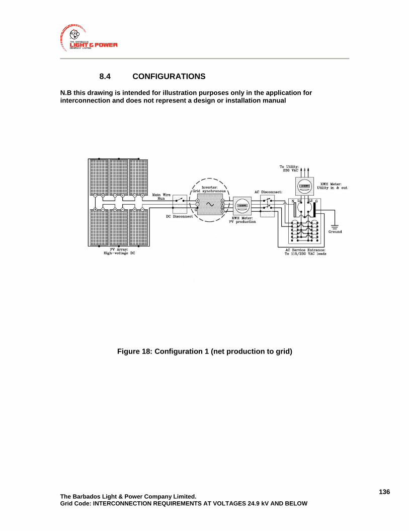
The Barbados Light & Power Company Limited. Grid Code: INTERCONNECTION REQUIREMENTS AT VOLTAGES 24.9 kV AND BELOW
136
8.4 CONFIGURATIONS
N.B this drawing is intended for illustration purposes only in the application for interconnection and does not represent a design or installation manual
Figure 18: Configuration 1 (net production to grid)

The Barbados Light & Power Company Limited. Grid Code: INTERCONNECTION REQUIREMENTS AT VOLTAGES 24.9 kV AND BELOW
137
N.B this drawing is intended for illustration purposes only in the application for interconnection and does not represent a design or installation manual
Figure 19: Configuration 2 (total production to grid)

The Barbados Light & Power Company Limited. Grid Code: INTERCONNECTION REQUIREMENTS AT VOLTAGES 24.9 kV AND BELOW
138
N.B this drawing is intended for illustration purposes only in the application for interconnection and does not represent a design or installation manual
Figure 20: Configuration of Battery Backed Inverter with Output to Critical Loads
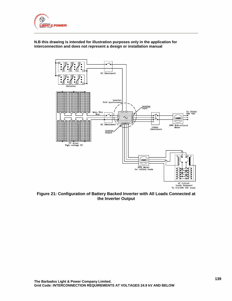
The Barbados Light & Power Company Limited. Grid Code: INTERCONNECTION REQUIREMENTS AT VOLTAGES 24.9 kV AND BELOW
139
N.B this drawing is intended for illustration purposes only in the application for interconnection and does not represent a design or installation manual
Figure 21: Configuration of Battery Backed Inverter with All Loads Connected at
the Inverter Output

The Barbados Light & Power Company Limited. Grid Code: INTERCONNECTION REQUIREMENTS AT VOLTAGES 24.9 kV AND BELOW
140
8.5 SDG INTERCONNECTION SITE INSPECTION
Verify size of inverters per application
Verify output frequency of inverter
Verify inverter disconnects in the event of an outage
Verify main breaker size per application
Check whether loads are being metered correctly
Verify bi-directional meter is in place
Check whether meter change is required
Verify a.c. disconnect switch is readily accessible to BLPC personnel
Verify label is in place near the utility disconnect switch
Check whether label is required on utility pole
Verify a.c. disconnect switch is grounded via equipment grounding conductor
Verify a.c. disconnect switch is visibly open
Verify a.c. disconnect switch is properly wired
Verify a.c. disconnect switch handle can be locked in the OFF position with a BLPC lock
Verify BLPC lock has been placed on utility disconnect switch
Verify utility disconnect switch has not been modified to accommodate the BLPC lock
Verify configuration conforms with Electrical One-line drawing & application
Verify measurement of SDG output is in place via production meter or other means
Note any other discrepancies
The Barbados Light & Power Company Limited. Grid Code: INTERCONNECTION REQUIREMENTS AT VOLTAGES 24.9 kV AND BELOW
141
9. APPENDIX A – BLPC CHARACTERISTICS (INFORMATIVE)
This section describes the characteristics of BLPC Distribution System and identifies aspects that must be taken into consideration when designing a generation connection. The LDG owner must be able to operate within the ranges specified in this section. In this document, BLPC’s Distribution System may refer to either three phase systems or single phase systems operating at voltages of 24.9 kV and below – includes systems falling under the definition of distribution lines and sub-transmission lines. This section contains no requirements for the interconnection of LDGs and has been provided for informational purposes only.
9.1 GENERAL CHARACTERISTICS
Most distribution circuits or feeders in BLPC’s Distribution System are supplied radially from a single substation (point of supply). In some areas, some feeders may have alternate points of supply, but will be operated with more than one source of supply only momentarily during switching operations. BLPC’s distribution feeders operate at the following voltages (phase-phase/phase-neutral): 24.9/14.4 kV, 11/6.35 kV.
9.2 SYSTEM FREQUENCY
The nominal frequency of BLPC’s system is 50 Hz. During normal operation (steady state), the frequency may deviate from 49.8 Hz to 50.2 Hz. Under contingencies the frequency deviations may be larger.
9.3 VOLTAGE
Customers supplied by a distribution feeder will nominally receive 11,000 volts but could be 2% above nominal at some locations, with and without distributed generation supplying power for minimum and maximum loading conditions. The operating voltages found on the distribution feeder vary depending on load
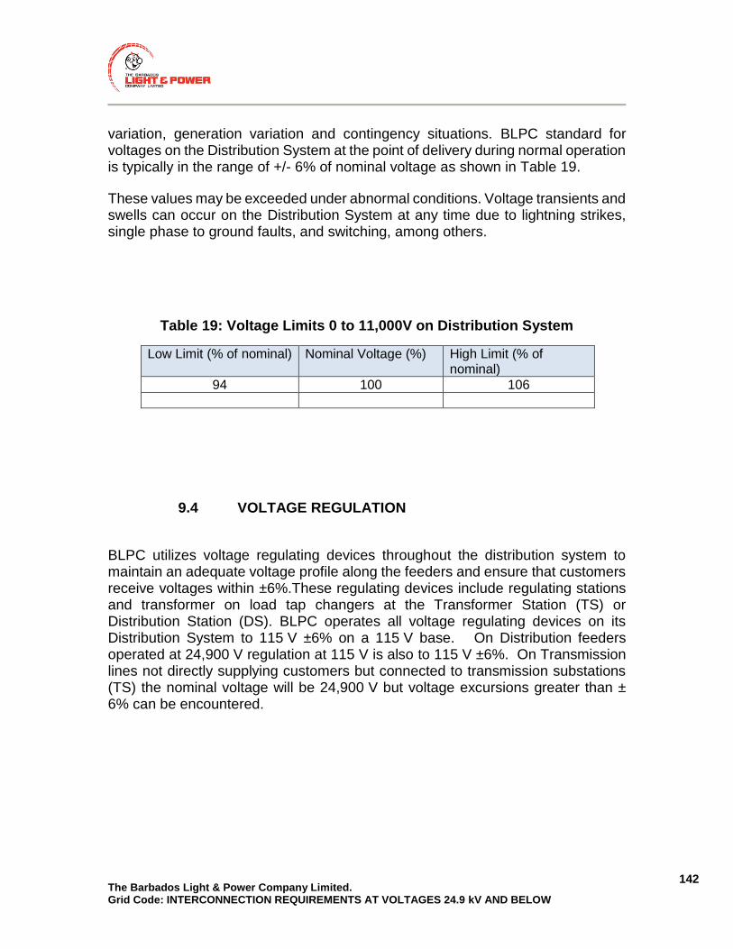
The Barbados Light & Power Company Limited. Grid Code: INTERCONNECTION REQUIREMENTS AT VOLTAGES 24.9 kV AND BELOW
142
variation, generation variation and contingency situations. BLPC standard for voltages on the Distribution System at the point of delivery during normal operation is typically in the range of +/- 6% of nominal voltage as shown in Table 19.
These values may be exceeded under abnormal conditions. Voltage transients and swells can occur on the Distribution System at any time due to lightning strikes, single phase to ground faults, and switching, among others.
Table 19: Voltage Limits 0 to 11,000V on Distribution System
Low Limit (% of nominal) Nominal Voltage (%) High Limit (% of nominal)
94 100 106
9.4 VOLTAGE REGULATION
BLPC utilizes voltage regulating devices throughout the distribution system to maintain an adequate voltage profile along the feeders and ensure that customers receive voltages within ±6%.These regulating devices include regulating stations and transformer on load tap changers at the Transformer Station (TS) or Distribution Station (DS). BLPC operates all voltage regulating devices on its Distribution System to 115 V ±6% on a 115 V base. On Distribution feeders operated at 24,900 V regulation at 115 V is also to 115 V ±6%. On Transmission lines not directly supplying customers but connected to transmission substations (TS) the nominal voltage will be 24,900 V but voltage excursions greater than ± 6% can be encountered.

The Barbados Light & Power Company Limited. Grid Code: INTERCONNECTION REQUIREMENTS AT VOLTAGES 24.9 kV AND BELOW
143
9.5 VOLTAGE AND CURRENT UNBALANCE
Voltage unbalance due to unbalanced loading and single phase voltage regulation is typically under 2% but may be higher in some areas. The voltage unbalance is calculated using the root-mean square (rms) voltage levels at the fundamental frequency measured at the service entrance (Point of Connection) under no-load and no generation as in the following equation:
Voltage Unbalance (%) =100XV2/V1 Where V2 is the negative sequence voltage V1 is the positive sequence voltage
Current unbalance is usually 10-15% of total feeder load current but may be higher in some areas. During abnormal conditions such as faults the unbalance may be very high (current unbalance may be significantly higher than 15%).
9.6 POWER QUALITY
In BLPC’s distribution system, all interconnected equipment must comply with BLPC’s standards for power quality. IEEE Std. 519, IEEE Recommended Practices and Requirements for Harmonic Control in Electric Power Systems, has been accepted by industry to provide guidance for appropriate performance and power quality limits such as voltage flicker and harmonic contribution limits. This standard states that the recommended practice for utilities is to limit individual frequency voltage harmonics to 3% of the fundamental frequency and the total voltage harmonic distortion (THD) to 5% on the utility side of the PCC.
9.7 FAULT LEVELS
Fault levels on BLPC’s distribution system vary greatly throughout the system. Factors, such as location, generation pattern, and contingencies all contribute to varying fault levels. These fault levels may also change with time as the system
The Barbados Light & Power Company Limited. Grid Code: INTERCONNECTION REQUIREMENTS AT VOLTAGES 24.9 kV AND BELOW
144
expands and new generation comes online. The CIA will provide better information regarding the fault level along a specific feeder.
9.8 SYSTEM GROUNDING
BLPC’s distribution facilities are typically operated as multi-grounded (for three-phase – systems). The transformer neutral at the substation is solidly grounded, .
9.9 BLPC DISTRIBUTION SYSTEM FEEDER PROTECTION
The general feeder protection scheme utilized on BLPC’s distribution system where LDGs are interconnecting is described below.. The feeder protections can be divided into two states: High Set Instantaneous – Instantaneous protection for close-in feeder faults is usually set to the first fuse on the feeder and traditionally employed High Set 50A/50NA elements. The current BLPC standard for feeders with LDGs interconnected is to use the High Set Instantaneous protection in addition to IDMT very inverse overcurrent and earth fault. Timed – Directionally supervised 51/51N overcurrent elements load/fault discrimination are used for timed protection of BLPC’s distribution feeders. All timed overcurrent elements on the distribution system are coordinated with each other to ensure that a minimum number of customers are affected in the case of permanent faults. For the timed overcurrent elements to function properly, all LDG sources (both positive sequence and zero sequence sources) need to be removed from the distribution
9.10 AUTOMATIC RECLOSING (FAULT CLEARING)
BLPC’s Distribution System utilizes some minimal automatic reclosing to quickly clear non-permanent faults on the distribution system, thus, quickly restoring supply. In general, feeder circuit breakers at Transmission Stations use non reclosing systems. Two substations currently utilize reclosing schemes: Hampton

The Barbados Light & Power Company Limited. Grid Code: INTERCONNECTION REQUIREMENTS AT VOLTAGES 24.9 kV AND BELOW
145
and Old Works Distribution Stations. If, after a number of preset reclose attempts the fault persists, then the recloser will lockout and stay open. The reclose ―dead time (time that the distribution line is de-energized between reclose attempts) varies depending on location and type of recloser. That data can be obtained from BLPC along with all other relevant protection data.
9.11 PHASING
Conductor phasing is standardized and as such, the phase sequence and the direction of rotation can be confirmed from BLPC.
9.12 MULTIPLE SOURCE (NETWORKED) SYSTEM
In no areas of BLPC’s Distribution System are there instances where portions of a distribution feeder are supplied from two different sources.
9.13 FREQUENCY OF INTERRUPTION
BLPC’s distribution feeders are mainly unshielded overhead lines. They are equipped with insulation levels adequate to withstand expected voltages. Lightning strikes directly to BLPC’s distribution line result in flashovers of the insulators on the feeder and result in protection systems tripping the distribution line. The faults may be temporary in which case a successful reclose will occur. Most faults on overhead distribution lines are temporary in nature. If they are permanent, and they trip the line, repair crews are dispatched and repair the feeder.
The Barbados Light & Power Company Limited. Grid Code: INTERCONNECTION REQUIREMENTS AT VOLTAGES 24.9 kV AND BELOW
146
9.14 ABNORMAL CONDITIONS
Many disturbances can occur on the distribution system at varying frequencies. These disturbances can include, but are not limited to the following:
- Faults on the system;
- Frequency excursions;
- Partial or complete loss of load;
- Transient over voltages – caused by lightning strikes or switching operations;
- Temporary overvoltages;
- Single phasing of the three phase system – caused by BLPC’s protection equipment, switching or broken conductors.
9.15 FEEDER DISCONNECTION
Distribution feeders may get disconnection by BLPC as part of BLPC’s load shedding scheme in order to mitigate frequency excursions. Generator facilities connected to these feeders will also be affected by these feeder supply interruptions, and are required to disconnect from BLPC’s distribution system in such cases.
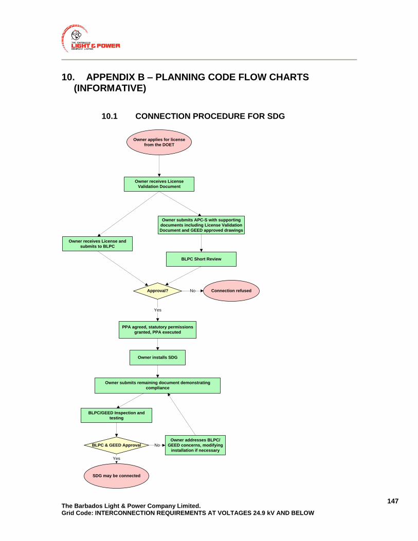
The Barbados Light & Power Company Limited. Grid Code: INTERCONNECTION REQUIREMENTS AT VOLTAGES 24.9 kV AND BELOW
147
10. APPENDIX B – PLANNING CODE FLOW CHARTS (INFORMATIVE)
10.1 CONNECTION PROCEDURE FOR SDG
BLPC Short Review
Approval?
BLPC/GEED Inspection and
testing
Connection refused
Owner receives License
Validation Document
BLPC & GEED Approval
PPA agreed, statutory permissions
granted, PPA executed
Owner installs SDG
Owner addresses BLPC/
GEED concerns, modifying
installation if necessary
SDG may be connected
Owner applies for license
from the DOET
Owner submits APC-S with supporting
documents including License Validation
Document and GEED approved drawings
Owner receives License and
submits to BLPC
No
Owner submits remaining document demonstrating
compliance
No
Yes
Yes

The Barbados Light & Power Company Limited. Grid Code: INTERCONNECTION REQUIREMENTS AT VOLTAGES 24.9 kV AND BELOW
148
10.2 CONNECTION PROCEDURE FOR LDG
BLPC carries out CIA (CIA-L)
Approval?
BLPC makes Connection
Offer (GCO-L)
Owner accepts GCO-L
PPA agreed
Connection refused
Owner receives License
Validation Document
BLPC & GEED Approval
PPA approved by FTC, statutory
permissions granted, PPA executed
Owner installs LDG
Commissioning & testing
coordinated with BLPC and GEED.
Results submitted to BLPC
LDG may be connected
Owner applies for license
from the DOET
Owner submits APC-L with supporting
documents including License Validation
Document and GEED approved drawings
Owner receives License and
submits to BLPC
No
Owner submits remaining document
demonstrating compliance
Yes
Yes
Owner addresses BLPC/
GEED concerns, modifying
installation if necessary
No

The Barbados Light & Power Company Limited. Grid Code: INTERCONNECTION REQUIREMENTS AT VOLTAGES 24.9 kV AND BELOW
149
11. APPENDIX C – FORMS: APPLICATION FOR PROPOSED CONNECTION (APC)
Following 6 pages: Application for Proposed Connection for Generators ≤ 150 kW (APC-S) then Following 12 pages: Application for Proposed Connection for Generators > 150 kW (APC-L)

Barbados Light & Power Co. – APPLICATION FOR PROPOSED CONNECTIONFOR GENERATORS ≤ 150 kW (APC-S)
Page 1 of 6
BARBADOS LIGHT & POWER COMPANY LIMITED
APPLICATION FOR PROPOSED CONNECTION
FOR GENERATORS ≤ 150 kW
(APC-S)
This Application Form is for new Customer Generators (Generator) with a proposed project size ≤ 150 kW wishing
to connect to the Barbados Light & Power Company (BLPC) system, and existing Customer Generators (Generator)
with a project size ≤ 150 kW wishing to revise/rework their existing connection.
Please return the completed form or mail to: Barbados Light & Power Co. Garrison Hill St. Michael BB11000
DATE (dd / mm / yyyy): / / Application Type: New Connection Application Connection Revision/Rework 1. Project Name:
2. Proposed In- Service Date (dd / mm / yyyy): / /
3. PROJECT SIZE: Nameplate Capacity: kW kVA
4. PROJECT LOCATION: Address 1:
Address 2: Address 3/:
Parish

Barbados Light & Power Co. – APPLICATION FOR PROPOSED CONNECTIONFOR GENERATORS ≤ 150 kW (APC-S)
Page 2 of 6
5. PROJECT INFORMATION: Choose a Single Point of Contact: Owner Consultant
Generator (Mandatory)
Owner (Mandatory)
Consultant (Optional)
Company/Person
Contact Person
Mailing Address Line 1
Mailing Address Line 2
Telephone
Cell
Fax
Preferred method of communication with Barbados Light & Power Co.: E-mail Telephone Mail Fax
6. CUSTOMER STATUS:
Existing Barbados Light & Power Company Customer? Yes No
If yes, Barbados Light & Power Co. 10-digit Account Number:
Customer name registered on this Account:
7. ENERGY TYPE: Biomass Solar
Wind Other (Please Specify)
8. CONNECTION TO BARBADOS LIGHT & POWER CO. DISTRIBUTION SYSTEM:
a. Proposed or existing Connection voltage to Barbados Light & Power Co.’s distribution system: kV
b. Distance from the Point of Connection to the PCC: km
c. Give nearest pole number:
d. Generator’s Connection Lines or Tap Line Facilities: If the Generator’s facilities include connection lines or a tap line on the Generator’s side of the PCC, provide the following:
Distance and conductor size of tap line on the Generator’s side of the PCC, or equivalent distance for Generator’s connection lines on the high-side of interface transformer(s): km.
Conductor size: 9. ELECTRICAL CHARACTERISTICS AT THE PCC
a. Already existing generator aggregate power rating: kW
New (additional) active power: kW
New (additional) maximum apparent power: kVA

Barbados Light & Power Co. – APPLICATION FOR PROPOSED CONNECTIONFOR GENERATORS ≤ 150 kW (APC-S)
Page 3 of 6
b. Fault contribution from Generator’s facilities, with the fault location at the PCC:
Three-phase generators: 3-phase short circuit MVA;
Single-phase generators: 1-phase short circuit MVA
10. REACTIVE POWER COMPENSATION
Reactive power compensation: None
Reactive power of compensation equipment:
Total: kVar, Per step: kVar, Number of steps:
Auto-controlled: No Yes
Resonance frequency:
11. SINGLE LINE DIAGRAM
Provide a Single Line Diagram of the Generator’s facilities including the PCC. Needs to include information about transformer(s), conductor lengths, switchgear, main breaker and renewable generator breaker size, meter location, overview of protection system including settings.
SLD Drawing Number Rev:
12. GENERATOR CHARACTERISTICS
Total number of generating unit(s):
For each generator unit within the Generator Facility, if units are different, please provide the following information:
Number of generator units of this type:
Manufacturer / Type or Model No: ( ) /
Rated capacity of each unit: kW kVA
Rated frequency: Hz Nominal machine voltage: kV
Machine Type:
Synchronous Machine (directly coupled) Synchronous Machine with inverter
Induction Generator Doubly Fed Induction Generator
PV Generator with Inverter Other (Please Specify)
Generator connecting on: single phase three phase
Limits of range of reactive power at the machine output:
i. Lagging (over-excited): kVAR power factor
ii. Leading (under-excited) kVAR power factor
13. GRID CODE COMPLIANCE DOCUMENTATION
Please attach product type conformance declarations (to be obtained from manufacturers) and/or type certificates, attesting compliance with the BLPC Grid Code.

Barbados Light & Power Co. – APPLICATION FOR PROPOSED CONNECTIONFOR GENERATORS ≤ 150 kW (APC-S)
Page 4 of 6
ATTACHED DOCUMENTS:
Item No.
Description Document No. No. of Pages
1
2
3
CHECKLIST Please ensure the following items are completed prior to submission. The application shall be returned if incomplete:
□ Completed form signed by the Generator Owner
□ Single Line Diagram (SLD) of the Generator’s facilities (APC-S Section 11), must be stamped by
the Government Electrical Engineering Department.
□ Grid Code compliance documents. For example conformance declarations and type certificates.

Barbados Light & Power Co. – APPLICATION FOR PROPOSED CONNECTIONFOR GENERATORS ≤ 150 kW (APC-S)
Page 5 of 6
NOTES:
By submitting an APC-S, the Proponent authorizes Barbados Light & Power Company (BLPC) to collect on the Proponents behalf any information pertaining to this application to facilitate the evaluation of the connection of the generation facility to BLPC’s Transmission and Distribution system.
Applicants are cautioned NOT to incur major expenses until BLPC approves the proposed generation facility.
All technical submissions (single line diagrams, etc.) must be signed by a Registered Engineer. For solar installations only, the SLD can be stamped by a Licensed Electrician.
All relevant fields are mandatory, except where noted. Incomplete applications shall be returned by BLPC.
GENERATOR’S FACILITIES:
“Point of Connection” means the point where the new Generator’s connection assets or new line expansion assets will be connected to BLPC’s Transmission and Distribution system.
“Point of Common Coupling” or “PCC” or “Point of Supply” means the point where the Generator’s facilities are to connect to BLPC’s Transmission and Distribution system.
The Point of Connection and the PCC may be the same, especially if the Generator’s facilities lie along the existing BLPC’s Transmission and Distribution system; or the PCC may be located somewhere between the Point of Connection and the Generator’s facilities if new line will be owned by BLPC.
Barbados Light & Power Co. – APPLICATION FOR PROPOSED CONNECTIONFOR GENERATORS ≤ 150 kW (APC-S)
Page 6 of 6
Signatures
Owner
Date (dd / mm / yyyy),: _______________________________________________________________
Name: _______________________________________________________________
Signature: _______________________________________________________________
Generator (only required if not identical to owner)
Date (dd / mm / yyyy), _______________________________________________________________
Name: _______________________________________________________________
Signature: _______________________________________________________________
Registered engineer/ Licensed Electrician (Solar applications only)
Date (dd / mm / yyyy),: _______________________________________________________________
Name: _______________________________________________________________
Signature: _______________________________________________________________

Barbados Light & Power Co. – APPLICATION FOR PROPOSED CONNECTION FOR GENERATORS > 150 kW (APC-L)
Page 1 of 12
BARBADOS LIGHT & POWER COMPANY LIMITED
APPLICATION FOR PROPOSED CONNECTION
FOR GENERATORS > 150 kW
(APC-L)
This Application Form is for Customer Generators (Generator) with a project size >150 kW, including:
New Customer Generators (Generator) applying for assessment of the proposed connection
New Customer Generators (Generator) applying for revision to their original CIA
Generators applying for CIA after rescinding a previous CIA. Note: Please include your previous CIA Project ID
# below.
Existing Generators to verify information related to current connection to the Barbados Light & Power Co.
(BLPC) system. It is part of the overall Power Purchase Agreement.
Please return the completed form or mail to: Barbados Light & Power Co. Garrison Hill St. Michael BB11000
DATE (dd / mm / yyyy): / / Application Type: New Proposed Connection CIA Revision/Rework Connection withdrawal 1. ORIGINAL CIA PROJECT ID# (IF APPLICABLE): Project Name:
2. Proposed In- Service Date (dd / mm / yyyy): / /
3. PROJECT SIZE: Nameplate Capacity: kW kVA
4. PROJECT LOCATION: Address 1:
Address 2: Address 3/:
Parish

Barbados Light & Power Co. – APPLICATION FOR PROPOSED CONNECTION FOR GENERATORS > 150 kW (APC-L)
Page 2 of 12
5. PROJECT INFORMATION: Choose a Single Point of Contact: Owner Consultant
Generator (Mandatory)
Owner (Mandatory)
Consultant (Optional)
Company/Person
Contact Person
Mailing Address Line 1
Mailing Address Line 2
Telephone
Cell
Fax
Preferred method of communication with Barbados Light & Power Co.: E-mail Telephone Mail Fax
6. CUSTOMER STATUS:
Existing Barbados Light & Power Company Customer? Yes No
If yes, Barbados Light & Power Co. 10-digit Account Number:
Customer name registered on this Account:
7. ENERGY TYPE: Biomass Solar
Wind Other (Please Specify)
8. CONNECTION TO BARBADOS LIGHT & POWER CO. DISTRIBUTION SYSTEM:
a. On a map provide the location of Generator’s facilities with proposed line routings for connection to BLPC’s Transmission and Distribution System. It should identify the Point of Connection, the PCC, and the location (i.e. on private property or public road right-of-ways) of new lines between the Generator’s facilities and the Point of Connection.
Drawing / Sketch No: Rev.:
b. Proposed or existing Connection voltage to BLPC’s Transmission and Distribution System: kV
c. GPS coordinates of the following: (Please give GPS co-ordinates in following format: Longitude, Latitude - Degree Decimal Format: * e.g. 49.392, -75.570) Point of Connection: PCC:
Generator facilities:
d. Distance from the Point of Connection to the PCC km
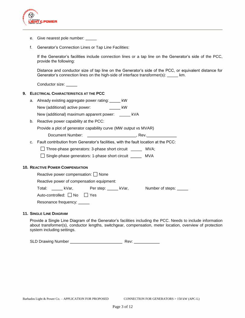
Barbados Light & Power Co. – APPLICATION FOR PROPOSED CONNECTION FOR GENERATORS > 150 kW (APC-L)
Page 3 of 12
e. Give nearest pole number:
f. Generator’s Connection Lines or Tap Line Facilities:
If the Generator’s facilities include connection lines or a tap line on the Generator’s side of the PCC, provide the following:
Distance and conductor size of tap line on the Generator’s side of the PCC, or equivalent distance for Generator’s connection lines on the high-side of interface transformer(s): km.
Conductor size: 9. ELECTRICAL CHARACTERISTICS AT THE PCC
a. Already existing aggregate power rating: kW
New (additional) active power: kW
New (additional) maximum apparent power: kVA
b. Reactive power capability at the PCC:
Provide a plot of generator capability curve (MW output vs MVAR)
Document Number: , Rev.
c. Fault contribution from Generator’s facilities, with the fault location at the PCC:
Three-phase generators: 3-phase short circuit MVA;
Single-phase generators: 1-phase short circuit MVA
10. REACTIVE POWER COMPENSATION
Reactive power compensation: None
Reactive power of compensation equipment:
Total: kVar, Per step: kVar, Number of steps:
Auto-controlled: No Yes
Resonance frequency:
11. SINGLE LINE DIAGRAM
Provide a Single Line Diagram of the Generator’s facilities including the PCC. Needs to include information about transformer(s), conductor lengths, switchgear, compensation, meter location, overview of protection system including settings.
SLD Drawing Number Rev:

Barbados Light & Power Co. – APPLICATION FOR PROPOSED CONNECTION FOR GENERATORS > 150 kW (APC-L)
Page 4 of 12
12. GENERATOR CHARACTERISTICS
Total number of generating unit(s):
For each generator unit within the Generator Facility, if units are different, please provide the following information:
Number of generator units of this type:
Manufacturer / Type or Model No: ( ) /
Rated capacity of each unit: kW kVA
Rated frequency: Hz Nominal machine voltage: kV
Machine Type:
Synchronous Machine (directly coupled) Synchronous Machine with inverter
Induction Generator Doubly Fed Induction Generator
PV Generator with Inverter Other (Please Specify):
Generator connecting on: single phase three phase
Limits of range of reactive power at the machine output:
iii. Lagging (over-excited): kVAR power factor
iv. Leading (under-excited) kVAR power factor
Starting inrush current: pu (multiple of full load current)
Generator terminal connection: delta star
Neutral grounding method of star connected generator:
Solid Ungrounded Impedance: R ohms X ohms
For Synchronous Units: Minimum power limit for stable operation: kW
Unsaturated reactances on: kVA base kV base
Direct axis subtransient reactance, Xd’’ pu
Direct axis transient reactance, Xd’ pu
Direct axis synchronous reactance, Xd pu
Zero sequence reactance, X0 pu
For Induction Units: Unsaturated reactances on: kVA base kV base
Direct axis subtransient reactance, Xd’’ pu
Direct axis transient reactance, Xd’ pu
Power factor correction capacitors are automatically switched off when generator breaker
opens Yes No
For converter-based units:
Line-commutated converter; Number of pulses:
Voltage-sourced converter; switching frequency:
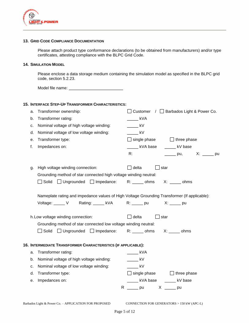
Barbados Light & Power Co. – APPLICATION FOR PROPOSED CONNECTION FOR GENERATORS > 150 kW (APC-L)
Page 5 of 12
13. GRID CODE COMPLIANCE DOCUMENTATION
Please attach product type conformance declarations (to be obtained from manufacturers) and/or type certificates, attesting compliance with the BLPC Grid Code.
14. SIMULATION MODEL Please enclose a data storage medium containing the simulation model as specified in the BLPC grid code, section 5.2.23. Model file name:
15. INTERFACE STEP-UP TRANSFORMER CHARACTERISTICS:
a. Transformer ownership: Customer / Barbados Light & Power Co.
b. Transformer rating: kVA
c. Nominal voltage of high voltage winding: kV
d. Nominal voltage of low voltage winding: kV
e. Transformer type: single phase three phase
f. Impedances on: kVA base kV base
R: pu, X: pu
g. High voltage winding connection: delta star
Grounding method of star connected high voltage winding neutral:
Solid Ungrounded Impedance: R: ohms X: ohms
Nameplate rating and impedance values of High Voltage Grounding Transformer (If applicable):
Voltage: V Rating: kVA R: pu X: pu
h. Low voltage winding connection: delta star
Grounding method of star connected low voltage winding neutral:
Solid Ungrounded Impedance: R: ohms X: ohms
16. INTERMEDIATE TRANSFORMER CHARACTERISTICS (IF APPLICABLE):
a. Transformer rating: kVA
b. Nominal voltage of high voltage winding: kV
c. Nominal voltage of low voltage winding: kV
d. Transformer type: single phase three phase
e. Impedances on: kVA base kV base
R pu X pu

Barbados Light & Power Co. – APPLICATION FOR PROPOSED CONNECTION FOR GENERATORS > 150 kW (APC-L)
Page 6 of 12
f. High voltage winding connection: delta star
Grounding method of star connected high voltage winding neutral:
Solid Ungrounded Impedance: R ohms X ohms
g. Low voltage winding connection: delta star
Grounding method of star connected low voltage winding neutral:
Solid Ungrounded Impedance: R ohms X ohms
17. LOAD INFORMATION:
a. Maximum load of the facility: kVA kW
b. Maximum load current (referred to the nominal voltage
at the connection point to Barbados Light & Power Co. system): A
c. Maximum inrush current to loads (referred to the nominal voltage
at the connection point to Barbados Light & Power Co. system): A
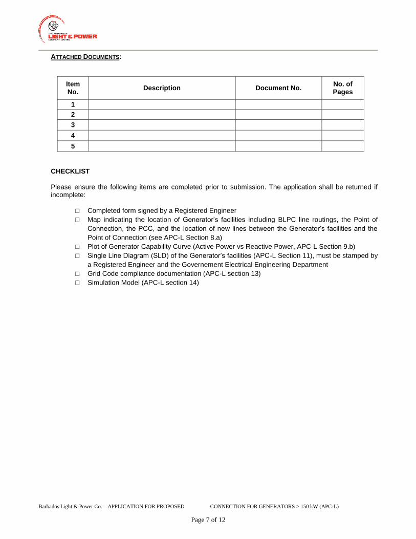
Barbados Light & Power Co. – APPLICATION FOR PROPOSED CONNECTION FOR GENERATORS > 150 kW (APC-L)
Page 7 of 12
ATTACHED DOCUMENTS:
Item No.
Description Document No. No. of Pages
1
2
3
4
5
CHECKLIST Please ensure the following items are completed prior to submission. The application shall be returned if incomplete:
□ Completed form signed by a Registered Engineer
□ Map indicating the location of Generator’s facilities including BLPC line routings, the Point of
Connection, the PCC, and the location of new lines between the Generator’s facilities and the
Point of Connection (see APC-L Section 8.a)
□ Plot of Generator Capability Curve (Active Power vs Reactive Power, APC-L Section 9.b)
□ Single Line Diagram (SLD) of the Generator’s facilities (APC-L Section 11), must be stamped by
a Registered Engineer and the Governement Electrical Engineering Department
□ Grid Code compliance documentation (APC-L section 13)
□ Simulation Model (APC-L section 14)

Barbados Light & Power Co. – APPLICATION FOR PROPOSED CONNECTION FOR GENERATORS > 150 kW (APC-L)
Page 8 of 12
APPENDIX A: ILLUSTRATIONS OF PCC AND POINT OF CONNECTION
FIGURE A-1: BARBADOS LIGHT & POWER CO. OWNS ENTIRE TAP LINE
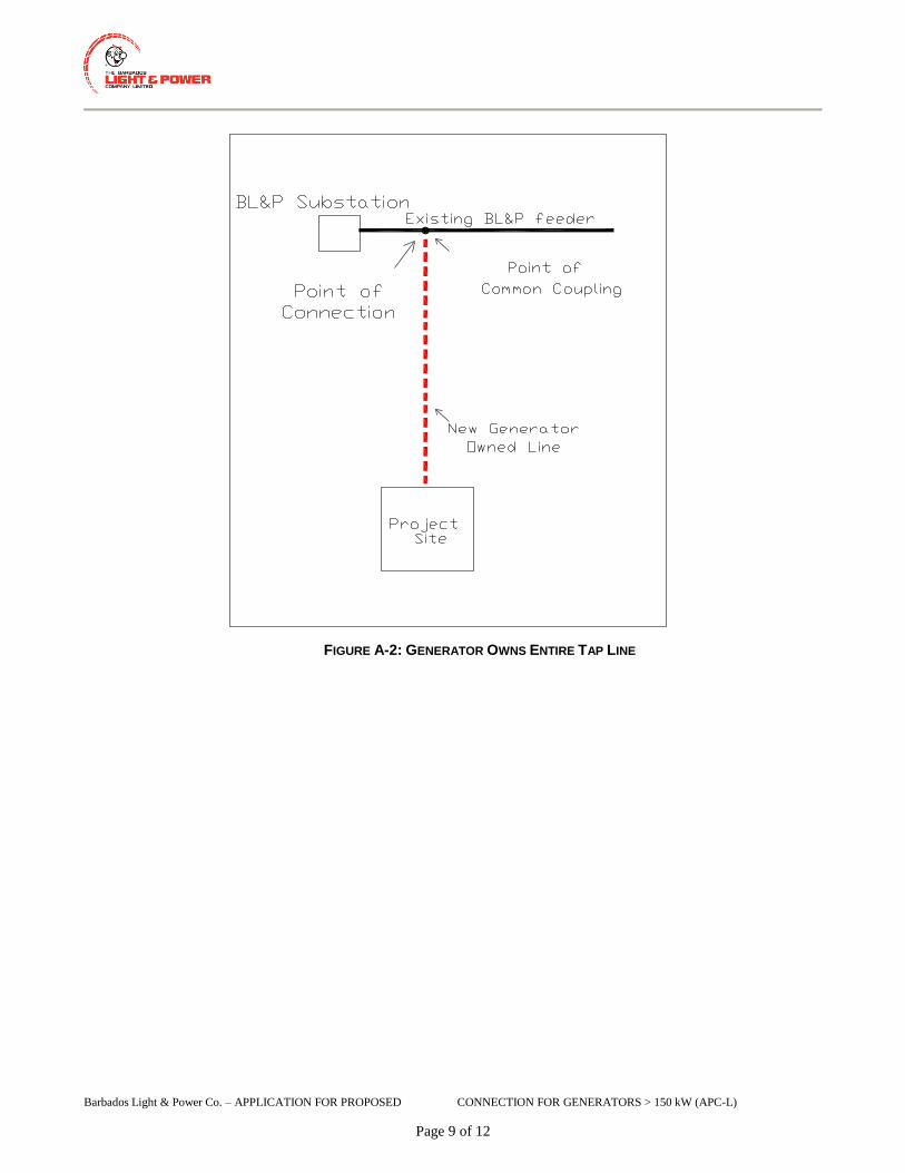
Barbados Light & Power Co. – APPLICATION FOR PROPOSED CONNECTION FOR GENERATORS > 150 kW (APC-L)
Page 9 of 12
FIGURE A-2: GENERATOR OWNS ENTIRE TAP LINE

Barbados Light & Power Co. – APPLICATION FOR PROPOSED CONNECTION FOR GENERATORS > 150 kW (APC-L)
Page 10 of 12
FIGURE A-3: BARBADOS LIGHT & POWER CO. OWNS A PORTION AND GENERATOR
OWNS A PORTION OF TAP LINE

Barbados Light & Power Co. – APPLICATION FOR PROPOSED CONNECTION FOR GENERATORS > 150 kW (APC-L)
Page 11 of 12
NOTES:
By submitting a APC-L, the Proponent authorizes Barbados Light & Power Company (BLPC) to collect on the Proponents behalf any information pertaining to this application to facilitate the evaluation of the connection of the generation facility to BLPC’s distribution system.
The term ‘High Voltage’ refers to the connection voltage to BLPC’s Transmission and Distribution system and ‘Low Voltage’ refers to the generation or any other intermediate voltage.
If this project requires line expansion work between the Point of Connection and PCC, BLPC will provide a cost estimate to construct any line located on a public road right-of-way as follows: a. Underground - The customer will be responsible for all civil work if the connection will be underground.
This includes trenching, laying of ducts and building of equipment foundations. b. Overhead - The customer will have the responsibility of providing a right of way for the poles to be
installed which our vehicles can access. This right of way shall be maintained by the Customer.
Applicants are cautioned NOT to incur major expenses until BLPC approves the proposed generation facility.
All technical submissions (single line diagrams, etc.) must be signed and sealed by a Registered Engineer.
All fields below are mandatory, except where noted. Incomplete applications shall be returned by BLPC.
GENERATOR’S FACILITIES AND NEW LINE MAP:
“Point of Connection” means the point where the new Generator’s connection assets or new line expansion assets will be connected to the BLPC’s Transmission and Distribution system.
“Point of Common Coupling” or “PCC” or “Point of Supply” means the point where the Generator’s facilities are to connect to BLPC’s Transmission and Distribution system.
The Point of Connection and the PCC may be the same, especially if the Generator’s facilities lie along the existing BLPC’s Transmission and Distribution system; or the PCC may be located somewhere between the Point of Connection and the Generator’s facilities if new line will be owned by BLPC. For illustration of the Point of Connection and the PCC, refer to Appendix A attached.

Barbados Light & Power Co. – APPLICATION FOR PROPOSED CONNECTION FOR GENERATORS > 150 kW (APC-L)
Page 12 of 12
Signatures
Owner
Date (dd / mm / yyyy),: _______________________________________________________________
Name: _______________________________________________________________
Signature: _______________________________________________________________
Generator (only required if not identical to owner)
Date (dd / mm / yyyy),: _______________________________________________________________
Name: _______________________________________________________________
Signature: _______________________________________________________________
Registered engineer, licensed in Barbados
Date (dd / mm / yyyy),: _______________________________________________________________
Name: _______________________________________________________________
Signature: _______________________________________________________________
Stamp: