grt1-drt operation manual
TRANSCRIPT

Cat. No. W454-E1-03
DeviceNet Communications Unit
SmartSliceGRT1-DRT
OPERATION MANUAL

SmartSlice GRT1-DRTDeviceNet Communications UnitOperation ManualRevised April 2008

iv
Notice:OMRON products are manufactured for use according to proper procedures by a qualified operatorand only for the purposes described in this manual.
The following conventions are used to indicate and classify precautions in this manual. Always heedthe information provided with them. Failure to heed precautions can result in injury to people or dam-age to property.
!DANGER Indicates an imminently hazardous situation which, if not avoided, will result in death orserious injury. Additionally, there may be severe property damage.
!WARNING Indicates a potentially hazardous situation which, if not avoided, could result in death orserious injury. Additionally, there may be severe property damage.
!Caution Indicates a potentially hazardous situation which, if not avoided, may result in minor ormoderate injury, or property damage.
OMRON Product ReferencesAll OMRON products are capitalized in this manual. The word “Unit” is also capitalized when it refers toan OMRON product, regardless of whether or not it appears in the proper name of the product.
The abbreviation “Ch,” which appears in some displays and on some OMRON products, often means“word” and is abbreviated “Wd” in documentation in this sense.
The abbreviation “PLC” means Programmable Controller. “PC” is used, however, in some Program-ming Device displays to mean Programmable Controller.
Visual AidsThe following headings appear in the left column of the manual to help you locate different types ofinformation.
Note Indicates information of particular interest for efficient and convenient opera-tion of the product.
1,2,3... 1. Indicates lists of one sort or another, such as procedures, checklists, etc.
OMRON, 2005All rights reserved. No part of this publication may be reproduced, stored in a retrieval system, or transmitted, in any form, orby any means, mechanical, electronic, photocopying, recording, or otherwise, without the prior written permission ofOMRON.
No patent liability is assumed with respect to the use of the information contained herein. Moreover, because OMRON is con-stantly striving to improve its high-quality products, the information contained in this manual is subject to change withoutnotice. Every precaution has been taken in the preparation of this manual. Nevertheless, OMRON assumes no responsibilityfor errors or omissions. Neither is any liability assumed for damages resulting from the use of the information contained inthis publication.
v

vi

TABLE OF CONTENTS
PRECAUTIONS . . . . . . . . . . . . . . . . . . . . . . . . . . . . . . . . . . . xv1 Intended Audience . . . . . . . . . . . . . . . . . . . . . . . . . . . . . . . . . . . . . . . . . . . . . . . . . . . . . . . . . xvi
2 General Precautions . . . . . . . . . . . . . . . . . . . . . . . . . . . . . . . . . . . . . . . . . . . . . . . . . . . . . . . . xvi
3 Safety Precautions . . . . . . . . . . . . . . . . . . . . . . . . . . . . . . . . . . . . . . . . . . . . . . . . . . . . . . . . . xvi
4 Operating Environment Precautions . . . . . . . . . . . . . . . . . . . . . . . . . . . . . . . . . . . . . . . . . . . xvii
5 Application Precautions. . . . . . . . . . . . . . . . . . . . . . . . . . . . . . . . . . . . . . . . . . . . . . . . . . . . . xviii
6 EC Directives. . . . . . . . . . . . . . . . . . . . . . . . . . . . . . . . . . . . . . . . . . . . . . . . . . . . . . . . . . . . . xix
SECTION 1Overview . . . . . . . . . . . . . . . . . . . . . . . . . . . . . . . . . . . . . . . . . 1
1-1 Overview of Slice I/O Terminals . . . . . . . . . . . . . . . . . . . . . . . . . . . . . . . . . . . . . . . . . . . . . . 2
1-2 Features and System Configuration. . . . . . . . . . . . . . . . . . . . . . . . . . . . . . . . . . . . . . . . . . . . 2
1-3 Specifications. . . . . . . . . . . . . . . . . . . . . . . . . . . . . . . . . . . . . . . . . . . . . . . . . . . . . . . . . . . . . 4
1-4 List of Available Units . . . . . . . . . . . . . . . . . . . . . . . . . . . . . . . . . . . . . . . . . . . . . . . . . . . . . . 6
1-5 Basic Operating Procedure . . . . . . . . . . . . . . . . . . . . . . . . . . . . . . . . . . . . . . . . . . . . . . . . . . 7
SECTION 2Component Names and Functions. . . . . . . . . . . . . . . . . . . . . 9
2-1 Nomenclature and Dimensions . . . . . . . . . . . . . . . . . . . . . . . . . . . . . . . . . . . . . . . . . . . . . . . 10
2-2 Node Address Settings and I/O Allocation . . . . . . . . . . . . . . . . . . . . . . . . . . . . . . . . . . . . . . 14
2-3 Unit Functions . . . . . . . . . . . . . . . . . . . . . . . . . . . . . . . . . . . . . . . . . . . . . . . . . . . . . . . . . . . . 23
SECTION 3Installation and Wiring . . . . . . . . . . . . . . . . . . . . . . . . . . . . . 39
3-1 Installation . . . . . . . . . . . . . . . . . . . . . . . . . . . . . . . . . . . . . . . . . . . . . . . . . . . . . . . . . . . . . . . 40
3-2 Power Supply Wiring. . . . . . . . . . . . . . . . . . . . . . . . . . . . . . . . . . . . . . . . . . . . . . . . . . . . . . . 44
3-3 Wiring DeviceNet Communications Cables . . . . . . . . . . . . . . . . . . . . . . . . . . . . . . . . . . . . . 47
3-4 Connecting the Turnback Cable . . . . . . . . . . . . . . . . . . . . . . . . . . . . . . . . . . . . . . . . . . . . . . 50
SECTION 4Setup and Operating Procedures . . . . . . . . . . . . . . . . . . . . . 51
4-1 Basic Operating Procedure and Example Configuration. . . . . . . . . . . . . . . . . . . . . . . . . . . . 52
4-2 Preparation for Operation . . . . . . . . . . . . . . . . . . . . . . . . . . . . . . . . . . . . . . . . . . . . . . . . . . . 53
4-3 Setting and Wiring Hardware . . . . . . . . . . . . . . . . . . . . . . . . . . . . . . . . . . . . . . . . . . . . . . . . 55
4-4 Starting Communications . . . . . . . . . . . . . . . . . . . . . . . . . . . . . . . . . . . . . . . . . . . . . . . . . . . 57
4-5 Checking Operation . . . . . . . . . . . . . . . . . . . . . . . . . . . . . . . . . . . . . . . . . . . . . . . . . . . . . . . . 60
SECTION 5Communications Characteristics . . . . . . . . . . . . . . . . . . . . . 61
5-1 Remote I/O Communications Characteristics . . . . . . . . . . . . . . . . . . . . . . . . . . . . . . . . . . . . 62
5-2 Message Communications Characteristics . . . . . . . . . . . . . . . . . . . . . . . . . . . . . . . . . . . . . . 66
vii

TABLE OF CONTENTS
SECTION 6Troubleshooting . . . . . . . . . . . . . . . . . . . . . . . . . . . . . . . . . . . 67
6-1 Troubleshooting Overview . . . . . . . . . . . . . . . . . . . . . . . . . . . . . . . . . . . . . . . . . . . . . . . . . . 68
6-2 LED Indicators and Error Processing . . . . . . . . . . . . . . . . . . . . . . . . . . . . . . . . . . . . . . . . . . 68
6-3 Reading the Error History with the DeviceNet Configurator . . . . . . . . . . . . . . . . . . . . . . . . 71
6-4 Other Errors . . . . . . . . . . . . . . . . . . . . . . . . . . . . . . . . . . . . . . . . . . . . . . . . . . . . . . . . . . . . . . 74
AppendicesA DeviceNet Explicit Messages . . . . . . . . . . . . . . . . . . . . . . . . . . . . . . . . . . . . . . . . . . . . . . . . 77
B Using Another Company's Master Unit . . . . . . . . . . . . . . . . . . . . . . . . . . . . . . . . . . . . . . . . 83
C Standard Models . . . . . . . . . . . . . . . . . . . . . . . . . . . . . . . . . . . . . . . . . . . . . . . . . . . . . . . . . . 91
D Power Consumption Tables . . . . . . . . . . . . . . . . . . . . . . . . . . . . . . . . . . . . . . . . . . . . . . . . . 95
E I/O Current Consumption . . . . . . . . . . . . . . . . . . . . . . . . . . . . . . . . . . . . . . . . . . . . . . . . . . . 97
Glossary . . . . . . . . . . . . . . . . . . . . . . . . . . . . . . . . . . . . . . . . . . 99
Index. . . . . . . . . . . . . . . . . . . . . . . . . . . . . . . . . . . . . . . . . . . . . 101
Revision History . . . . . . . . . . . . . . . . . . . . . . . . . . . . . . . . . . . 103
viii

About this Manual:
This manual describes the installation and operation of the DeviceNet Communications Unit for Slice I/O Terminals and includes the sections described below. The DeviceNet Communications Unit for SliceI/O Terminals is an interface Unit that connects Slice I/O Units with a DeviceNet Master.
Please read this manual carefully and be sure you understand the information provided beforeattempting to install or operate the DeviceNet Communications Units. Be sure to read the precau-tions provided in the following section.
The following manuals also cover information related to DeviceNet applications. Use the DeviceNetOperation Manual together with other required manuals.
Precautions provides general precautions for planning, installing, and operating the DeviceNet Com-munications Unit and related devices.
Section 1 provides an overview of the DeviceNet Communications Unit with information such as thefeatures and system configuration.
Section 2 describes the DeviceNet Communications Unit’s components, describes the Unit’s functionsin detail, and explains how to allocate I/O.
Section 3 explains how to install and wire the DeviceNet Communications Unit and Slice I/O Termi-nals.
Section 4 describes the procedures required to begin actual communications between the DeviceNetCommunications Unit and Slice I/O Terminals.
Section 5 provides information on communications using the remote I/O communications function andmessage communications function, such as response times and transmission delays.
Section 6 explains how to monitor and correct errors that occur in a DeviceNet Communications Unitor Slice I/O Unit, interpret the Unit’s LED indicators, and read the error history from the DeviceNet Con-figurator.
Appendix explains how to handle EDS setting files required for multivendor environments and how tolist the device profile of the DeviceNet Communications Unit and information on related products.
Manual Contents Cat. No.
DeviceNet Communications Unit for Slice I/O Terminals Operation Manual (this manual)
Describes the specifications, functions, operating procedures, and applications of the DeviceNet Communications Unit, which allows Slice I/O Units to be set, controlled, and monitored through DeviceNet.
W454
GRT1 Series Slice I/O Units Operation Manual
Describes the models, specifications, functions, operating proce-dures, and applications of GRT1-series Slice I/O Units.
W455
DeviceNet Operation Manual
Describes the configuration and construction of a DeviceNet network, including installation procedures and specifications for cables, con-nectors, and other connection devices, as well as information on functions, operating procedures, and applications.Read this manual carefully and be sure you understand the informa-tion provided before attempting to use DeviceNet.
W267
CS/CJ Series DeviceNet Units Operation Manual
Describes the specifications, functions, operating procedures, and applications of CS-series and CJ-series DeviceNet Units. (A CS/CJ-series DeviceNet Unit can operate as both a DeviceNet master and DeviceNet slave at the same time.)
W380
DeviceNet Configurator Ver. 2.@ Operation Manual
Describes the operating procedures of the DeviceNet Configurator. The DeviceNet Configurator can be used to configure, set, and main-tain a DeviceNet system through an easy-to-use graphical interface. Refer to this manual when necessary.
W382
ix

!WARNING Failure to read and understand the information provided in this manual may result in per-sonal injury or death, damage to the product, or product failure. Please read each sectionin its entirety and be sure you understand the information provided in the section andrelated sections before attempting any of the procedures or operations given.
x

Read and Understand this ManualPlease read and understand this manual before using the product. Please consult your OMRON representative if you have any questions or comments.
Warranty and Limitations of Liability
WARRANTY
OMRON's exclusive warranty is that the products are free from defects in materials and workmanship for a period of one year (or other period if specified) from date of sale by OMRON.
OMRON MAKES NO WARRANTY OR REPRESENTATION, EXPRESS OR IMPLIED, REGARDING NON-INFRINGEMENT, MERCHANTABILITY, OR FITNESS FOR PARTICULAR PURPOSE OF THE PRODUCTS. ANY BUYER OR USER ACKNOWLEDGES THAT THE BUYER OR USER ALONE HAS DETERMINED THAT THE PRODUCTS WILL SUITABLY MEET THE REQUIREMENTS OF THEIR INTENDED USE. OMRON DISCLAIMS ALL OTHER WARRANTIES, EXPRESS OR IMPLIED.
LIMITATIONS OF LIABILITY
OMRON SHALL NOT BE RESPONSIBLE FOR SPECIAL, INDIRECT, OR CONSEQUENTIAL DAMAGES, LOSS OF PROFITS OR COMMERCIAL LOSS IN ANY WAY CONNECTED WITH THE PRODUCTS, WHETHER SUCH CLAIM IS BASED ON CONTRACT, WARRANTY, NEGLIGENCE, OR STRICT LIABILITY.
In no event shall the responsibility of OMRON for any act exceed the individual price of the product on which liability is asserted.
IN NO EVENT SHALL OMRON BE RESPONSIBLE FOR WARRANTY, REPAIR, OR OTHER CLAIMS REGARDING THE PRODUCTS UNLESS OMRON'S ANALYSIS CONFIRMS THAT THE PRODUCTS WERE PROPERLY HANDLED, STORED, INSTALLED, AND MAINTAINED AND NOT SUBJECT TO CONTAMINATION, ABUSE, MISUSE, OR INAPPROPRIATE MODIFICATION OR REPAIR.
xi

Application Considerations
SUITABILITY FOR USE
OMRON shall not be responsible for conformity with any standards, codes, or regulations that apply to the combination of products in the customer's application or use of the products.
At the customer's request, OMRON will provide applicable third party certification documents identifying ratings and limitations of use that apply to the products. This information by itself is not sufficient for a complete determination of the suitability of the products in combination with the end product, machine, system, or other application or use.
The following are some examples of applications for which particular attention must be given. This is not intended to be an exhaustive list of all possible uses of the products, nor is it intended to imply that the uses listed may be suitable for the products:
• Outdoor use, uses involving potential chemical contamination or electrical interference, or conditions or uses not described in this manual.
• Nuclear energy control systems, combustion systems, railroad systems, aviation systems, medical equipment, amusement machines, vehicles, safety equipment, and installations subject to separate industry or government regulations.
• Systems, machines, and equipment that could present a risk to life or property.
Please know and observe all prohibitions of use applicable to the products.
NEVER USE THE PRODUCTS FOR AN APPLICATION INVOLVING SERIOUS RISK TO LIFE OR PROPERTY WITHOUT ENSURING THAT THE SYSTEM AS A WHOLE HAS BEEN DESIGNED TO ADDRESS THE RISKS, AND THAT THE OMRON PRODUCTS ARE PROPERLY RATED AND INSTALLED FOR THE INTENDED USE WITHIN THE OVERALL EQUIPMENT OR SYSTEM.
PROGRAMMABLE PRODUCTS
OMRON shall not be responsible for the user's programming of a programmable product, or any consequence thereof.
xii

Disclaimers
CHANGE IN SPECIFICATIONS
Product specifications and accessories may be changed at any time based on improvements and other reasons.
It is our practice to change model numbers when published ratings or features are changed, or when significant construction changes are made. However, some specifications of the products may be changed without any notice. When in doubt, special model numbers may be assigned to fix or establish key specifications for your application on your request. Please consult with your OMRON representative at any time to confirm actual specifications of purchased products.
DIMENSIONS AND WEIGHTS
Dimensions and weights are nominal and are not to be used for manufacturing purposes, even when tolerances are shown.
PERFORMANCE DATA
Performance data given in this manual is provided as a guide for the user in determining suitability and does not constitute a warranty. It may represent the result of OMRON's test conditions, and the users must correlate it to actual application requirements. Actual performance is subject to the OMRON Warranty and Limitations of Liability.
ERRORS AND OMISSIONS
The information in this manual has been carefully checked and is believed to be accurate; however, no responsibility is assumed for clerical, typographical, or proofreading errors, or omissions.
xiii

xiv

PRECAUTIONS
This section provides general precautions for installing and using the DeviceNet Communications Unit and related devices.
The information contained in this section is important for the safe and reliable application of the DeviceNetCommunications Unit. You must read this section and understand the information contained before attempting toset up or operate a DeviceNet network using a DeviceNet Communications Unit.
1 Intended Audience . . . . . . . . . . . . . . . . . . . . . . . . . . . . . . . . . . . . . . . . . . . . . xvi2 General Precautions . . . . . . . . . . . . . . . . . . . . . . . . . . . . . . . . . . . . . . . . . . . . xvi3 Safety Precautions. . . . . . . . . . . . . . . . . . . . . . . . . . . . . . . . . . . . . . . . . . . . . . xvi4 Operating Environment Precautions . . . . . . . . . . . . . . . . . . . . . . . . . . . . . . . . xvii5 Application Precautions . . . . . . . . . . . . . . . . . . . . . . . . . . . . . . . . . . . . . . . . . xviii6 EC Directives . . . . . . . . . . . . . . . . . . . . . . . . . . . . . . . . . . . . . . . . . . . . . . . . . xix
xv

Intended Audience 1
1 Intended AudienceThis manual is intended for the following personnel, who must also haveknowledge of electrical systems (an electrical engineer or the equivalent).
• Personnel in charge of purchasing FA systems.
• Personnel in charge of designing FA systems.
• Personnel in charge of installing and connecting FA systems.
• Personnel in charge of managing FA systems and facilities.
2 General PrecautionsThe user must operate the product according to the specifications describedin the operation manuals.
Before using the product under conditions which are not described in themanual or applying the product to nuclear control systems, railroad systems,aviation systems, vehicles, combustion systems, medical equipment, amuse-ment machines, safety equipment, and other systems, machines, and equip-ment that may have a serious influence on lives and property if usedimproperly, consult your OMRON representative.
Make sure that the ratings and performance characteristics of the product aresufficient for the systems, machines, and equipment, and be sure to providethe systems, machines, and equipment with redundant safety mechanisms.
This manual provides information for installing and operating OMRONDeviceNet products. Be sure to read this manual before operation and keepthis manual close at hand for reference during operation.
!WARNING It is extremely important that a PLC and all PLC Units be used for the speci-fied purpose and under the specified conditions, especially in applications thatcan directly or indirectly affect human life. You must consult with your OMRONrepresentative before applying a PLC system to the above mentioned applica-tions.
3 Safety Precautions
!WARNING Never attempt to disassemble any Units or touch the terminal block whilepower is being supplied. Doing so may result in serious electrical shock orelectrocution.
!WARNING Provide safety measures in external circuits (i.e., not in the ProgrammableController), including the following items, to ensure safety in the system if anabnormality occurs due to malfunction of the PLC or another external factoraffecting the PLC operation. Not doing so may result in serious accidents.
• Emergency stop circuits, interlock circuits, limit circuits, and similar safetymeasures must be provided in external control circuits.
• The PLC will stop operation when its self-diagnosis function detects anyerror or when a severe failure alarm (FALS) instruction is executed. As acountermeasure for such errors, external safety measures must be pro-vided to ensure safety in the system.
xvi
Operating Environment Precautions 4
• The PLC outputs may remain ON or OFF due to deposits on or burning ofthe output relays, or destruction of the output transistors. As a counter-measure for such problems, external safety measures must be providedto ensure safety in the system.
• When the 24-V DC output (service power supply to the PLC) is over-loaded or short-circuited, the voltage may drop and result in the outputsbeing turned OFF. As a countermeasure for such problems, externalsafety measures must be provided to ensure safety in the system.
• Slice I/O Terminals will continue operating even if one or more I/O Units isremoved from or falls out of the Slice I/O Terminal, i.e., the other I/O Unitswill continue control operations, including outputs. As a countermeasurefor such a possibility, external safety measures must be provided toensure safety in the system.
!WARNING The CPU Unit refreshes I/O even when the program is stopped (i.e., even inPROGRAM mode). Confirm safety thoroughly in advance before changing thestatus of any part of memory allocated to Output Units, Special I/O Units, orCPU Bus Units. Any changes to the data allocated to any Unit may result inunexpected operation of the loads connected to the Unit. Any of the followingoperations may result in changes to memory status.
• Transferring I/O memory data to the CPU Unit from a ProgrammingDevice
• Changing present values in memory from a Programming Device
• Force-setting/-resetting bits from a Programming Device
• Transferring I/O memory files from a Memory Card or EM file memory tothe CPU Unit
• Transferring I/O memory from a host computer or from another PLC on anetwork
4 Operating Environment PrecautionsInstall the system properly according to the directions in this manual.
Do not operate the control system in the following places.
• Locations subject to direct sunlight.
• Locations subject to temperatures or humidity outside the range specifiedin the specifications.
• Locations subject to condensation as the result of severe changes in tem-perature.
• Locations subject to corrosive or flammable gases.
• Locations subject to dust (especially iron dust) or salts.
• Locations subject to water, oil, or chemicals (General Units)
• Locations subject to acid or chemicals.
• Locations subject to shock or vibration.
Take appropriate and sufficient countermeasures when installing systems inthe following locations:
• Locations subject to static electricity or other forms of noise.
• Locations subject to strong electromagnetic fields.
• Locations subject to possible exposure to radioactivity.
• Locations close to power supplies.
xvii

Application Precautions 5
!Caution The operating environment of the PLC System can have a large effect on thelongevity and reliability of the system. Improper operating environments canlead to malfunction, failure, and other unforeseeable problems with the PLCSystem. Be sure that the operating environment is within the specified condi-tions at installation and remains within the specified conditions during the lifeof the system.
5 Application PrecautionsObserve the following precautions when using the DeviceNet Communica-tions Unit.
• Fail-safe measures must be taken by the customer to ensure safety in theevent of incorrect, missing, or abnormal signals caused by broken signallines, momentary power interruptions, or other causes.
• Provide external interlock circuits, limit circuits, and other safety circuits inaddition to any provided within the PLC to ensure safety.
• Use the power supplies specified in the operation manuals.
• If the system is installed at a site with poor power supply conditions, takeappropriate measures to ensure that the power supply remains within therated voltage and frequency specifications.
• Provide circuit breakers and other safety measures to provide protectionagainst shorts in external wiring.
• Always ground the system to 100 Ω or less when installing the system toprotect against electrical shock.
• Mount the PLC securely on DIN Track or with screws.
• Always turn OFF the power supply when mounting a DeviceNet Commu-nications Unit.
• Always turn OFF the communications power supply and the power sup-plies to the PLC and Slaves before attempting any of the following.
• Mounting or removing a Unit such as an I/O Unit, CPU Unit, MemoryCassette, or Master Unit.
• Mounting or removing Remote I/O Terminal circuit sections.
• Assembling any devices or racks.
• Setting rotary switches.
• Connecting or wiring cables.
• Connecting or disconnecting connectors.
• Do not attempt to disassemble, repair, or modify any Units.
• Be sure that all the terminal screws are tightened to the torque specifiedin the relevant manuals. Loose screws may cause fire, malfunction, ordamage the Unit.
• Be sure that all the mounting screws and cable connector screws aretightened to the torque specified in the relevant manuals.
• Be sure that all the communications connector screws are tightenedsecurely. (The communications connector screw torque is 0.5 to 0.6 N•m.)
• Do not remove the label from a Unit before wiring. Always remove thelabel after completing wiring, however, to ensure proper heat dispersion.
• Use the correct wiring components when wiring.
• Use crimp terminals for wiring. Do not connect bare stranded wiresdirectly to terminals.
• Double-check all wiring before turning ON the power supply.
xviii

EC Directives 6
• When wiring or performing other tasks, do not allow metal objects such aswire strands to enter the Unit.
• Always follow the electrical specifications for terminal polarity, communi-cations path wiring, power supply wiring, and I/O jumpers. Incorrect wiringcan cause failures.
• Always wire the Unit as shown in the manual.
• Be sure to press terminals until they are fully seated.
• Mount Units only after checking terminal blocks completely.
• Be sure that the communications cable connectors and other items withlocking devices are properly locked into place.
• Do not drop the Unit or subject the Unit to excessive vibration or shock.Doing so may cause malfunction or damage to the Unit.
• Use the special packing box when transporting the Unit. Ensure that theproduct is handled carefully so that no excessive vibration or impact isapplied to the product during transportation.
• Check the user program for proper execution before actually running itwith the system.
• Do not bend or pull the cables excessively.
• When connecting communications cables, always turn OFF the PLCpower supply, all Slave power supplies, and all communications powersupplies.
• Observe the following precautions when wiring the communicationscables.
• Wire the communications cables separately from the power lines orhigh-tension lines.
• Do not bend the communications cables excessively.
• Do not pull on the communications cables excessively.
• Do not place objects on top of the communications cables.
• Route communications cables inside ducts.
• Always enable the scan list before operation.
• Before clearing the scan list of a Unit that has user-allocated remote I/O,always confirm that no errors occur after the I/O Area setting is changedto fixed allocation.
• When adding a new node to the network, check that the new node’s baudrate is the same as the baud rate set on the other nodes.
• Do not extend connection distances beyond the ranges given in the spec-ifications.
6 EC DirectivesDeviceNet products conform to EMS and low-voltage level directives as fol-lows:
EMC DirectivesOMRON devices that comply with EC Directives also conform to the relatedEMC standards, so that they can more easily be built in to other devices or theoverall machine. The actual products have been checked for conformity toEMC standards. Whether they conform to the standards in the system usedby the customer, however, must be checked by the customer.
EMC-related performance of the OMRON devices that comply with EC Direc-tives will vary depending on the configuration, wiring, and other conditions of
xix
EC Directives 6
the equipment or control panel on which the OMRON devices are installed.The customer must, therefore, perform the final check to confirm that devicesand the overall machine conform to EMC standards.
1,2,3... 1. The DeviceNet Communications Units are designed for installation insidecontrol panels. All DeviceNet Units must be installed within control panels.
2. Use reinforced insulation or double insulation for the DC power suppliesused for the communications power supply, internal circuit power supply,and the I/O power supplies. The power supplies must also be able to pro-vide stable output for 10 ms when a momentary power interruption occursat the input.
3. The DeviceNet Communications Units conform to the EN61131-2 (Immu-nity Zone A), EN61000-6-2, and EN61000-6-4 standards, but the radiatedemission characteristics (10-m regulations) may vary depending on theconfiguration of the control panel used, other devices connected to thecontrol panel, wiring, and other conditions. You must therefore confirm thatthe overall machine or equipment complies with EC Directives.
The following examples shows how to reduce noise.
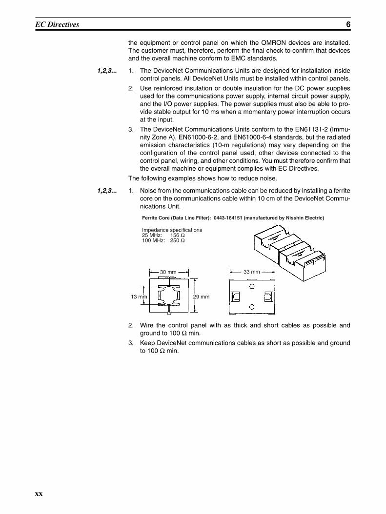
1,2,3... 1. Noise from the communications cable can be reduced by installing a ferritecore on the communications cable within 10 cm of the DeviceNet Commu-nications Unit.
2. Wire the control panel with as thick and short cables as possible andground to 100 Ω min.
3. Keep DeviceNet communications cables as short as possible and groundto 100 Ω min.
Ferrite Core (Data Line Filter): 0443-164151 (manufactured by Nisshin Electric)
Impedance specifications25 MHz: 156 Ω 100 MHz: 250 Ω
30 mm
13 mm 29 mm
33 mm
xx

SECTION 1Overview
This section provides an overview of the DeviceNet Communications Unit, including basic information such as the featuresand system configuration.
1-1 Overview of Slice I/O Terminals . . . . . . . . . . . . . . . . . . . . . . . . . . . . . . . . . . 2
1-2 Features and System Configuration . . . . . . . . . . . . . . . . . . . . . . . . . . . . . . . . 2
1-2-1 Features. . . . . . . . . . . . . . . . . . . . . . . . . . . . . . . . . . . . . . . . . . . . . . . 2
1-2-2 System Configuration . . . . . . . . . . . . . . . . . . . . . . . . . . . . . . . . . . . . 4
1-3 Specifications . . . . . . . . . . . . . . . . . . . . . . . . . . . . . . . . . . . . . . . . . . . . . . . . . 4
1-3-1 Communications Specifications . . . . . . . . . . . . . . . . . . . . . . . . . . . . 4
1-3-2 General Specifications . . . . . . . . . . . . . . . . . . . . . . . . . . . . . . . . . . . 5
1-3-3 DeviceNet Communications Unit Specifications . . . . . . . . . . . . . . . 5
1-4 List of Available Units . . . . . . . . . . . . . . . . . . . . . . . . . . . . . . . . . . . . . . . . . . 6
1-5 Basic Operating Procedure . . . . . . . . . . . . . . . . . . . . . . . . . . . . . . . . . . . . . . . 7
1
Overview of Slice I/O Terminals Section 1-1
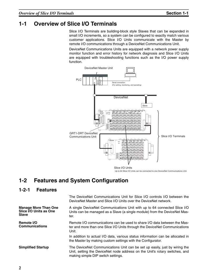
1-1 Overview of Slice I/O TerminalsSlice I/O Terminals are building-block style Slaves that can be expanded insmall I/O increments, so a system can be configured to exactly match variouscustomer applications. Slice I/O Units communicate with the Master byremote I/O communications through a DeviceNet Communications Unit.
DeviceNet Communications Units are equipped with a network power supplymonitor function and error history for network diagnosis and Slice I/O Unitsare equipped with troubleshooting functions such as the I/O power supplyfunction.
1-2 Features and System Configuration
1-2-1 FeaturesThe DeviceNet Communications Unit for Slice I/O controls I/O between theDeviceNet Master and Slice I/O Units over the DeviceNet network.
Manage More Than One Slice I/O Units as One Slave
A single DeviceNet Communications Unit with up to 64 connected Slice I/OUnits can be managed as a Slave (a single module) from the DeviceNet Mas-ter.
Remote I/O Communications
Remote I/O communications can be used to share I/O data between the Mas-ter and more than one Slice I/O Units through the DeviceNet CommunicationsUnit.
In addition to actual I/O data, various status information can be allocated inthe Master by making custom settings with the Configurator.
Simplified Startup The DeviceNet Communications Unit can be set up easily, just by wiring theUnit, setting the DeviceNet node address on the Unit’s rotary switches, andmaking simple DIP switch settings.
DeviceNet
PLCSerial connection(For setting, monitoring, and operating)
Slave
GRT1-DRT DeviceNet Communications Unit
Slice I/O UnitsUp to 64 Slice I/O Units can be connected to one DeviceNet Communications Unit.
Slice I/O Terminals
DeviceNet Master Unit
2
Features and System Configuration Section 1-2
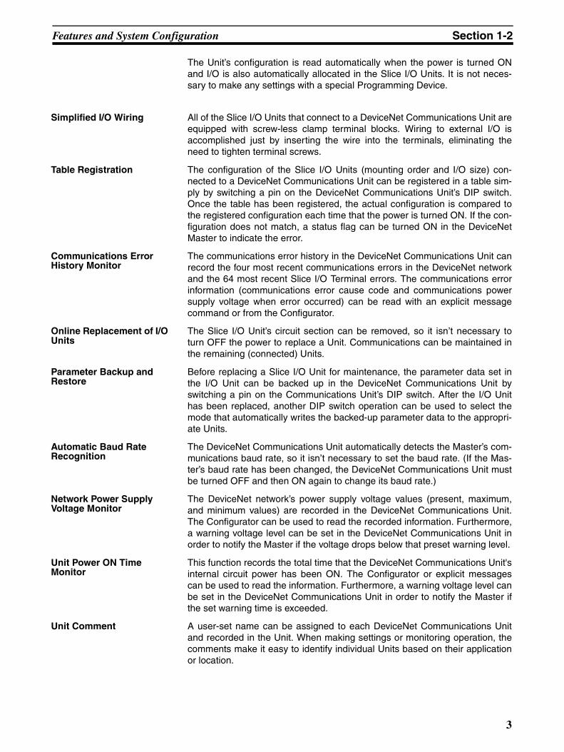
The Unit’s configuration is read automatically when the power is turned ONand I/O is also automatically allocated in the Slice I/O Units. It is not neces-sary to make any settings with a special Programming Device.
Simplified I/O Wiring All of the Slice I/O Units that connect to a DeviceNet Communications Unit areequipped with screw-less clamp terminal blocks. Wiring to external I/O isaccomplished just by inserting the wire into the terminals, eliminating theneed to tighten terminal screws.
Table Registration The configuration of the Slice I/O Units (mounting order and I/O size) con-nected to a DeviceNet Communications Unit can be registered in a table sim-ply by switching a pin on the DeviceNet Communications Unit’s DIP switch.Once the table has been registered, the actual configuration is compared tothe registered configuration each time that the power is turned ON. If the con-figuration does not match, a status flag can be turned ON in the DeviceNetMaster to indicate the error.
Communications Error History Monitor
The communications error history in the DeviceNet Communications Unit canrecord the four most recent communications errors in the DeviceNet networkand the 64 most recent Slice I/O Terminal errors. The communications errorinformation (communications error cause code and communications powersupply voltage when error occurred) can be read with an explicit messagecommand or from the Configurator.
Online Replacement of I/O Units
The Slice I/O Unit’s circuit section can be removed, so it isn’t necessary toturn OFF the power to replace a Unit. Communications can be maintained inthe remaining (connected) Units.
Parameter Backup and Restore
Before replacing a Slice I/O Unit for maintenance, the parameter data set inthe I/O Unit can be backed up in the DeviceNet Communications Unit byswitching a pin on the Communications Unit’s DIP switch. After the I/O Unithas been replaced, another DIP switch operation can be used to select themode that automatically writes the backed-up parameter data to the appropri-ate Units.
Automatic Baud Rate Recognition
The DeviceNet Communications Unit automatically detects the Master’s com-munications baud rate, so it isn’t necessary to set the baud rate. (If the Mas-ter’s baud rate has been changed, the DeviceNet Communications Unit mustbe turned OFF and then ON again to change its baud rate.)
Network Power Supply Voltage Monitor
The DeviceNet network’s power supply voltage values (present, maximum,and minimum values) are recorded in the DeviceNet Communications Unit.The Configurator can be used to read the recorded information. Furthermore,a warning voltage level can be set in the DeviceNet Communications Unit inorder to notify the Master if the voltage drops below that preset warning level.
Unit Power ON Time Monitor
This function records the total time that the DeviceNet Communications Unit'sinternal circuit power has been ON. The Configurator or explicit messagescan be used to read the information. Furthermore, a warning voltage level canbe set in the DeviceNet Communications Unit in order to notify the Master ifthe set warning time is exceeded.
Unit Comment A user-set name can be assigned to each DeviceNet Communications Unitand recorded in the Unit. When making settings or monitoring operation, thecomments make it easy to identify individual Units based on their applicationor location.
3

Specifications Section 1-3
Last Maintenance Date The dates on which maintenance is performed can be written to theDeviceNet Communications Unit. The recorded date shows when mainte-nance is required next.
1-2-2 System ConfigurationThe DeviceNet Communications Unit connects to the Master by a networkcable and it connects to the Slice I/O Units by directly coupling the Units withslide connectors.
The I/O Unit data in the DeviceNet Communications Unit is shared with theMaster’s Input and Output Areas through the DeviceNet network. The I/OUnits’ data is collected in the DeviceNet Communications Unit and exchangedwith the Master asynchronously.
It is also possible to send explicit message commands addressed to theDeviceNet Communications Unit.
Note Always install an End Unit on the last I/O Unit in the last node.
1-3 Specifications
1-3-1 Communications Specifications
CS/CJ-series DeviceNet Unit (master)
DeviceNet
PLCSerial connection(For setting, monitoring, and operating)
CX-One (CX-Integrator)
Explicit messages
Used to monitor operation and writeparameters to the Slice I/O Units orDeviceNet Communications Unit.
Remote I/O communicationsI/O data is collected from the connected Slice I/O Units and exchanged in a batch with the Master.
I/O data first goes to theCommunications Unit.
Slave
GRT1-DRT DeviceNetCommunications Unit
I/O Units
GRT1-TBR Right Turnback Unit
GRT1-TBL Left Turnback Unit
GCN2-100 Turnback Cable (1 m)
GRT1-END End Unit
Up to 64 Slice I/O Units can be connected to one DeviceNet Communications Unit.
Up to 2 sets of Turnback Unitscan be used per Communications Unit
Item Specification
Number of connectable Slice I/O Units
64 Units max.
Baud rate 3 Mbps
Communications signal level RS-485
Turnback Cable Length 1 m max., up to 2 cables can be connected.
4
Specifications Section 1-3
1-3-2 General Specifications
1-3-3 DeviceNet Communications Unit Specifications
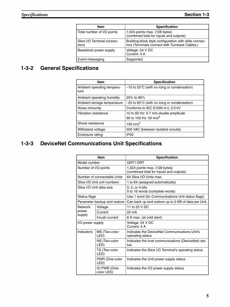
Total number of I/O points 1,024 points max. (128 bytes) (combined total for inputs and outputs)
Slice I/O Terminal connec-tions
Building-block style configuration with slide connec-tors (Terminals connect with Turnback Cables.)
Baseblock power supply Voltage: 24 V DCCurrent: 4 A
Event messaging Supported.
Item Specification
Item Specification
Ambient operating tempera-ture
−10 to 55°C (with no icing or condensation)
Ambient operating humidity 25% to 85%
Ambient storage temperature −25 to 65°C (with no icing or condensation)
Noise immunity Conforms to IEC 61000-4-4, 2.0 kV
Vibration resistance 10 to 60 Hz: 0.7 mm double amplitude60 to 150 Hz: 50 m/s2
Shock resistance 150 m/s2
Withstand voltage 500 VAC (between isolated circuits)
Enclosure rating IP20
Item Specification
Model number GRT1-DRT
Number of I/O points 1,024 points max. (128 bytes) (combined total for inputs and outputs)
Number of connectable Units 64 Slice I/O Units max.
Slice I/O Unit unit numbers 1 to 64 (assigned automatically)
Slice I/O Unit data size 0, 2, or 4 bits0 to 16 words (complete words)
Status flags Use 1 word (for Communications Unit status flags)
Parameter backup and restore Can back up and restore up to 2 KB of data per Unit.
Network power supply
Voltage 11 to 25 V DC
Current 22 mA
Inrush current 6 A max. (at cold start)
I/O power supply Voltage: 24 V DCCurrent: 4 A
Indicators MS (Two-color LED)
Indicates the DeviceNet Communications Unit’s operating status
NS (Two-color LED)
Indicates the host communications (DeviceNet) sta-tus.
TS (Two-color LED)
Indicates the Slice I/O Terminal’s operating status
PWR (One-color LED)
Indicates the Unit power supply status
IO PWR (One-color LED)
Indicates the I/O power supply status
5

List of Available Units Section 1-4
1-4 List of Available UnitsThe following table shows the Units that can be used in Slice I/O Terminals aswell as the devices that can be connected. Refer to the GRT1 Series Slice I/OUnits Operation Manual for details, such as Slice I/O Unit specifications.
Switches Node-address setting switches
Decimal rotary switchesSet the Unit’s node address as a DeviceNet Slave.
Other switches DIP switchPin 1: Create/Enable registered table (Switch from OFF to ON to register the table. Leave ON to enable the table.)Pin 2: Always OFF.
Pin 3: Automatic restore (Auto-restore enabled when ON.)Pin 4: Backup trigger (Switch from OFF to ON two times to backup the parameter data.)
Connector One open connector for DeviceNet, with screwsThe XWG4-05C4-TF-D Multi-drop Connector can be connected.
Terminals Two terminals for I/O power supplyTwo terminals for Unit power supply
Power consumption 3 W
Power consumption per block 80 W max. (Unit power supply)(If more than 80 W is required, separate into blocks using Turnback Units.)
Block separation Basic block plus up to two other blocks
I/O current consumption 4 A max.
Weight 137 g
Accessories XW4G-05C4-TF-D Connector
For multi-drop node connection. Connector screws provided.
Item Specification
Model number
Specifications
GRT1-DRT DeviceNet Communications Unit (Up to 64 I/O Units can be con-nected.)
GRT1-ID4 Slice I/O Unit with 4 DC inputs (NPN)
GRT1-ID4-1 Slice I/O Unit with 4 DC inputs (PNP)
GRT1-OD4 Slice I/O Unit with 4 DC outputs (NPN)
GRT1-OD4-1 Slice I/O Unit with 4 DC outputs (PNP)
GRT1-ROS2 Slice I/O Unit with 2 relay outputs
GRT1-AD2 Slice I/O Unit with 2 analog inputs
GRT1-DA2V Slice I/O Unit with 2 voltage analog outputs
GRT1-DA2C Slice I/O Unit with 2 current analog outputs
GRT1-END End Unit
GRT1-PD2 I/O Power Supply Unit
GRT1-TBR Right Turnback Unit (Mounts to the right side of I/O Terminal.)
GRT1-TBL Left Turnback Unit (Mounts to the left side of I/O Terminal.)
GCN2-100 Turnback Cable (1 m)
6

Basic Operating Procedure Section 1-5
1-5 Basic Operating ProcedureThe following procedure shows the basic steps required before using the SliceI/O Terminals.
Operating Procedure
1,2,3... 1. Connect the DeviceNet Communications Unit to the Master and connectthe desired Slice I/O Units.
2. Turn ON the power supply to the DeviceNet Communications Unit.
3. Turn ON (from OFF to ON) pin 1 of the DIP switch on the front of the De-viceNet Communications Unit. When pin 1 is turned ON, the existing SliceI/O Unit configuration (connection order and I/O size) is registered in theDeviceNet Communications Unit as a registered table. (After the table isregistered, leave pin 1 ON to enable the table.)
4. The next time that the power is turned ON, the connected Slice I/O Unitconfiguration at that moment is automatically compared to the registeredtable and any Slice I/O Units that do not match the registered table (con-nection order or I/O size) will not participate in I/O communications. I/Ocommunications will start with the other Slice I/O Units.
Note (1) When a communications error has occurred, the DeviceNet Communica-tions Unit’s TS indicator will flash red and the affected Slice I/O Unit’s TSindicator will flash red. At the same time, the error code and error detailscode will be stored in the DeviceNet Communications Unit’s error history.
(2) For details on the operating procedures, refer to SECTION 4 Setup andOperating Procedures.
7

Basic Operating Procedure Section 1-5
8

SECTION 2Component Names and Functions
This section describes the names and functions of the components in the DeviceNet Communications Unit.
2-1 Nomenclature and Dimensions . . . . . . . . . . . . . . . . . . . . . . . . . . . . . . . . . . . . 10
2-1-1 LED Indicators . . . . . . . . . . . . . . . . . . . . . . . . . . . . . . . . . . . . . . . . . 11
2-1-2 Switch Settings . . . . . . . . . . . . . . . . . . . . . . . . . . . . . . . . . . . . . . . . . 13
2-2 Node Address Settings and I/O Allocation . . . . . . . . . . . . . . . . . . . . . . . . . . . 14
2-2-1 Setting the Node Address . . . . . . . . . . . . . . . . . . . . . . . . . . . . . . . . . 14
2-2-2 Unit Numbers of Slice I/O Units (Automatically Allocated) . . . . . . 15
2-2-3 I/O Allocation to the Slice I/O Terminal’s Master Unit . . . . . . . . . . 16
2-2-4 I/O Allocation with the Configurator (Ver. 2.@ or Higher) . . . . . . . 20
2-3 Unit Functions. . . . . . . . . . . . . . . . . . . . . . . . . . . . . . . . . . . . . . . . . . . . . . . . . 23
2-3-1 Table Registration Function . . . . . . . . . . . . . . . . . . . . . . . . . . . . . . . 24
2-3-2 Backup Function. . . . . . . . . . . . . . . . . . . . . . . . . . . . . . . . . . . . . . . . 26
2-3-3 Automatic Restore Function . . . . . . . . . . . . . . . . . . . . . . . . . . . . . . . 26
2-3-4 Online Replacement Function . . . . . . . . . . . . . . . . . . . . . . . . . . . . . 28
2-3-5 Automatic Baud Rate Recognition . . . . . . . . . . . . . . . . . . . . . . . . . . 29
2-3-6 Network Power Supply Voltage Monitor . . . . . . . . . . . . . . . . . . . . . 29
2-3-7 Unit Conduction Time Monitor . . . . . . . . . . . . . . . . . . . . . . . . . . . . 30
2-3-8 Unit Comments. . . . . . . . . . . . . . . . . . . . . . . . . . . . . . . . . . . . . . . . . 32
2-3-9 Network Communications Error History Monitor . . . . . . . . . . . . . . 34
2-3-10 I/O Communications Error History Monitor . . . . . . . . . . . . . . . . . . 35
2-3-11 Last Maintenance Date . . . . . . . . . . . . . . . . . . . . . . . . . . . . . . . . . . . 37
9

Nomenclature and Dimensions Section 2-1
2-1 Nomenclature and Dimensions
Nomenclature
Dimensions (mm)
DIP SwitchSets the I/O allocation method and registers the I/O Unitconfiguration information.SW1 (REGS): Create/enable registration table.SW2 (I/O): Always OFFSW3 (ADR): Automatic restoreSW4 (BACK): Backup trigger
Rotary switchesSet the Unit's node address as a DeviceNetSlave. Set a decimal node address between0 and 63.
DeviceNet communications connectorConnect the DeviceNet network'scommunications cable to this connector.
Indicators
Unit power supply terminalsConnect the power supply for the Unit's internal circuits andthe connected Slice I/O Units' internal circuits.
I/O power supply terminals
Connect the power supply for the connected Slice I/O Units'external I/O.
Refer to 2-1-1 LED Indicators for details.
24
40
62
7058
384
12
3
10

Nomenclature and Dimensions Section 2-1
Slice I/O Unit Structure
The Slice I/O Unit is made up of three blocks, as shown in the following dia-gram. When replacement is necessary, individual blocks can be replaced.
Note Refer to the GRT1 Series Slice I/O Units Operation Manual (W455) for detailssuch as Slice I/O Unit specifications and standard models.
2-1-1 LED IndicatorsThe DeviceNet Communications Unit’s LED indicators indicate the status ofthe Unit, the DeviceNet network, and communications between the Unit andSlice I/O Units.
Main Block
Base BlockThis is the Slice I/O Unit's bus connector.If a faulty Unit is being replaced, thisblock can be left attached during online replacement.
Terminal BlockThis is the Slice I/O Unit's terminal block.If a faulty Unit is being replaced, the wiring can beleft attached and just the Main Block replaced.
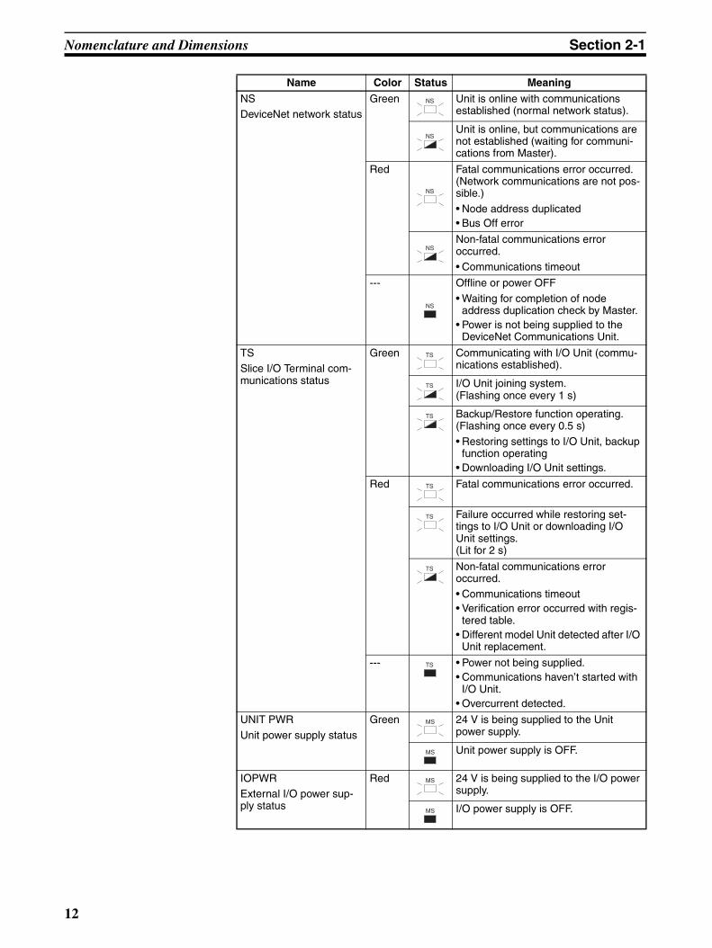
Name Color Status Meaning
MS
DeviceNet Communica-tions Unit status
Green Normal status (DeviceNet Communica-tions Unit operating normally)
Red Non-recoverable, fatal error occurred.• Watchdog timer error• RAM error
Recoverable, non-fatal error occurred.• EEPROM checksum error• Parameter setting logic error• EEPROM hardware error
--- No power
• The Unit’s power supply is OFF.• The Unit is being reset.• The Unit is waiting for initialization.
MS
MS
MS
MS
11
Nomenclature and Dimensions Section 2-1
NSDeviceNet network status
Green Unit is online with communications established (normal network status).
Unit is online, but communications are not established (waiting for communi-cations from Master).
Red Fatal communications error occurred. (Network communications are not pos-sible.)
• Node address duplicated• Bus Off error
Non-fatal communications error occurred.• Communications timeout
--- Offline or power OFF
• Waiting for completion of node address duplication check by Master.
• Power is not being supplied to the DeviceNet Communications Unit.
TSSlice I/O Terminal com-munications status
Green Communicating with I/O Unit (commu-nications established).
I/O Unit joining system.(Flashing once every 1 s)
Backup/Restore function operating.(Flashing once every 0.5 s)
• Restoring settings to I/O Unit, backup function operating
• Downloading I/O Unit settings.
Red Fatal communications error occurred.
Failure occurred while restoring set-tings to I/O Unit or downloading I/O Unit settings.(Lit for 2 s)
Non-fatal communications error occurred.• Communications timeout• Verification error occurred with regis-
tered table.• Different model Unit detected after I/O
Unit replacement.
--- • Power not being supplied.• Communications haven’t started with
I/O Unit.• Overcurrent detected.
UNIT PWR
Unit power supply status
Green 24 V is being supplied to the Unit power supply.
Unit power supply is OFF.
IOPWRExternal I/O power sup-ply status
Red 24 V is being supplied to the I/O power supply.
I/O power supply is OFF.
Name Color Status Meaning
NS
NS
NS
NS
NS
TS
TS
TS
TS
TS
TS
TS
MS
MS
MS
MS
12

Nomenclature and Dimensions Section 2-1
2-1-2 Switch SettingsNote The DeviceNet Communications Unit detects the Master’s communications
baud rate automatically, so it is not necessary to set the baud rate.
Rotary Switches
Use the rotary switches to set the Unit’s DeviceNet node address between 00and 63. (Do not set values 64 to 99.)
DIP Switch The DIP switch is used for the Unit settings and operations described below.The DIP switch functions are only introduced here. For details, refer to 2-3Unit Functions.
Create/Enable Registration Table(REGS, pin 1)
If pin 1 is turned from OFF to ON while the Unit’s power is ON, the existingSlice I/O Unit configuration (connection order and I/O size) is registered in theDeviceNet Communications Unit as a registered table.
If pin 1 is ON when the Unit’s power is turned ON, the actual Slice I/O Unitconfiguration at startup is automatically compared to the registered table. AnySlice I/O Units that do not match the registered table will not participate inSlice I/O communications.
I/O Allocation Mode(I/O, pin 2)
Always leave pin 2 set to OFF.
Automatic Restore(ADR, pin 3)
When pin 1 is ON (registered table enabled) and pin 3 is ON, parameter data isautomatically restored to the Slice I/O Units that had parameter data backedup.
×10
DeviceNetNode address setting
×1
01
23
4 5 67
8
9 01
23
4 5 67
8
9
ON1
2
3
4
REGS
I/O
ADR
BACK
Switch setting Function
ON Registered table is enabled. (If there is a verification error, the affected Unit will not participate in communications.)
OFF Registered table is disabled. (All Units participate in communica-tions.)
OFF to ON Register I/O Unit table. (Of course, pin 1 must be turned OFF to ON while the Unit is ON.)
ON to OFF Clear registered table.
Switch setting Function
ON Automatic restore function enabled (when pin 1 is ON).
OFF Automatic restore function disabled.
13

Node Address Settings and I/O Allocation Section 2-2
Backup Trigger(BACK, pin 4)
When pin 1 is ON (registered table enabled) and pin 4 is turned OFF to ON, theparameter data of all connected Slice I/O Units is backed up in the Communi-cations Unit.
Note The factory setting is OFF for all DIP switch pins.
2-2 Node Address Settings and I/O AllocationI/O words in the Master (the CPU Unit’s I/O memory) are allocated to the SliceI/O Terminal based on the DeviceNet Communications Unit’s node addresssetting. Once the DeviceNet node address is set, I/O will be allocated to theSlice I/O Terminal by default and remote I/O communications will start auto-matically.
Note When the power is turned ON, unit numbers are allocated automatically to theSlice I/O Units in the Slice I/O Terminal.
2-2-1 Setting the Node AddressThe Slice I/O Terminal’s node address as a DeviceNet Slave is set with therotary switches on the front of the DeviceNet Communications Unit. The nodeaddress determines the starting word of the area allocated to the Slice I/OTerminal.
Switch setting Function
ON Switch ON to OFF to ON to start the parameter backup (when pin 1 is ON).
OFF ---
ON OFF ON
1 s 1 s 1 s
The backup operation starts after pin 4 is turnedfrom ON to OFF to ON within 3 seconds.
DeviceNetMaster Unit
Set the first allocatedword with the nodeaddress setting.
I/O memory
Slice I/OTerminal
CPU Unit
The DeviceNet CommunicationsUnit's DeviceNet node addresssetting determines the first wordof the I/O memory area allocatedin the CPU Unit.
DeviceNet Communications Unit Slice I/O Terminal
14

Node Address Settings and I/O Allocation Section 2-2
DeviceNet Node Address Setting
The left rotary switch sets the ten's digit, and the right rotary switch sets theone's digit. Any number in the allowed range (00 to 63) can be set as long asit is not set on another node (Master, Slave, or Configurator) in the network.
Note (1) Always turn OFF the DeviceNet communications power supply and De-viceNet Communications Unit’s power supply before setting the node ad-dress.
(2) The factory default setting for the node address is 00.
(3) If the node address is duplicated on another node, a node address dupli-cation error will occur and the Unit will not be able to join the network.
2-2-2 Unit Numbers of Slice I/O Units (Automatically Allocated)The numbers used to identify the Slice I/O Units in a Slice I/O Terminal arecalled the Slice I/O Units’ unit numbers. These unit numbers are allocatedautomatically from left to right starting from #1, when the power is turned ON.It is not necessary for the user to set these numbers.
Note The unit numbers allocated automatically to the Slice I/O Units are unrelatedto the DeviceNet node address set with the rotary switches.
×10 ×1
DeviceNet node address setting
DeviceNetCommunications Unit
The Slice I/O Units' unit numbers are allocatedautomatically in order, from left to right.
I/O #1
I/O #2
I/O #3
I/O #4
I/O #64
: :
15
Node Address Settings and I/O Allocation Section 2-2
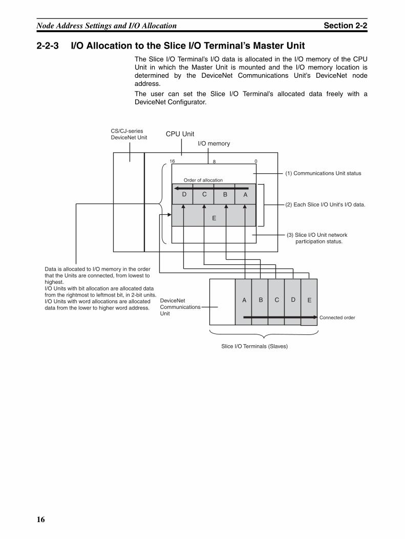
2-2-3 I/O Allocation to the Slice I/O Terminal’s Master UnitThe Slice I/O Terminal’s I/O data is allocated in the I/O memory of the CPUUnit in which the Master Unit is mounted and the I/O memory location isdetermined by the DeviceNet Communications Unit’s DeviceNet nodeaddress.
The user can set the Slice I/O Terminal’s allocated data freely with aDeviceNet Configurator.
E
Connected order
CPU UnitCS/CJ-seriesDeviceNet Unit
I/O memory
ABCD
E
DeviceNetCommunicationsUnit
A B C D
Slice I/O Terminals (Slaves)
Data is allocated to I/O memory in the orderthat the Units are connected, from lowest tohighest.I/O Units with bit allocation are allocated datafrom the rightmost to leftmost bit, in 2-bit units.I/O Units with word allocations are allocated data from the lower to higher word address.
0816
Order of allocation(1) Communications Unit status
(2) Each Slice I/O Unit's I/O data.
(3) Slice I/O Unit network participation status.
16

Node Address Settings and I/O Allocation Section 2-2
I/O Allocation Example
I/O data is allocated to the I/O Units in the order that they are connected to theCommunications Unit, regardless of the I/O Units’ models. Unless specialallocation data settings are selected with the Configurator, data is allocatedfrom the first word starting with the Communications Unit’s status flags andthen the leftmost I/O Unit’s data.
Data in the Master’s input and output areas is allocated to the Slice I/O Unitsbased on their unit numbers.
Note I/O Units with bit allocation (such as the GRT1-ID4/OD4) are allocated data in2-bit units. I/O Units with word allocation (such as the GRT1-AD2) are allo-cated data in 1-word units. The following example shows the allocation to anOutput Unit.
Allocated Data Patterns
The following kinds of data can be allocated in the Master. The Configuratorcan be used to freely select the kinds/combination of data allocated. If theConfigurator isn’t used to select the data pattern, the default setting is used,which is I/O data + Communications Unit status flags (pattern number 1 in thefollowing table).
Data Allocated to Master
Note The Communications Unit’s status flags and Slice I/O Units’ communicationsparticipating/withdrawn flags cannot be allocated in the output area.
+2
+3
#4
+1
Word 15 8 0
#1 #3 #2
#6
Word 15 8 0
#5
#2 ID4
#3 ID4
#4 AD2
#5 OD4
#1 ID4
#6 ROS2
Some areas may be unusedwhen data is allocated.
Communi-cationsUnit
Communications Unit status
Unused
First word First word Unused
Output areaInput area
#2 OD4
#3 OD4
#4 ROS2
#5 OD4
#1 OD4
#6 DA2
+1
+2
#6
+0
Word
#1
+3
#5
#2 #3 #4 #5
Communi-cationsUnit
Data is allocated in 2-bit unitsto I/O Units that require 4 bits, so there may be unused areasas shown in the following table.
Unused
Slice I/O Terminal configuration
15 8 0
Allocated data pattern
1 I/O data (inputs) + Communications Unit status flags
2 I/O data (inputs and outputs) only
3 Communications Unit status flags only
4 Slice I/O Unit communications participating/withdrawn flags only
17

Node Address Settings and I/O Allocation Section 2-2
Allocated Data Size
Note When allocating data, be sure that it does not exceed the maximum that canbe allocated (64 words).
Status Flags The status flags can be allocated in the Master independently or together withthe I/O data. There are two kinds of status flags, the Communications Unit’sstatus flags and I/O Units’ communications participating/withdrawn flags, andthese status flags must be allocated in separate areas.
Communications Unit’s Status Flags
These flags can be used to monitor the status of the connection with the Mas-ter and the status of Slice I/O Units connected to the Communications Unit.The status flags take up 2 words and the information is transferred to the Mas-ter.
With the default data pattern (pattern 1), these status flags are allocated in theMaster together with the I/O data. The status flags can also be read with theConfigurator or an explicit message command.
Data type Data size
I/O data (input and output) When only the actual I/O data is allocated:64 input words max. or 64 output words max.The GRT1-ID4(-1) and GRT1-OD4(-1) use 4 bits per Unit.The GRT1-ROS2 uses 2 bits.
Communications Unit status flags 1 word
Slice I/O Unit communications participating/withdrawn flags
Participating flags: 4 wordsWithdrawn flags: 4 words
Total: 8 words
I/O data (inputs) + Communica-tions Unit status flags
Amount of I/O data being used + 1 word
Bit Content Description
0 Slice I/O Bus Communications Error Flag Monitors the status of Slice I/O Terminal communications.
1 Reserved ---
2 Slice I/O Unit Warning Flag0: Normal; 1: Error detected
Indicates a major Slice I/O Unit error. This flag goes ON when there is an error in any one of the connected Slice I/O Units.
3 Reserved ---
4 Slice I/O Unit Alarm Flag
0: Normal; 1: Error detected
Indicates a minor Slice I/O Unit error. This flag goes ON when there is an error in any one of the connected Slice I/O Units.
Status flags (16 bits)
Master CPU Unit
DeviceNet Communications Unit
First word
I/O data (4 bits)
Status flagsSlice I/O Unit (4 inputs)
Input Area
18

Node Address Settings and I/O Allocation Section 2-2
Slice I/O Unit Participating/Withdrawn Flags
These flags can be used to monitor the connection status (participating orwithdrawn) of the Slice I/O Units connected to the Communications Unit.There are always 8 words allocated to the Participating/Withdrawn Flags (4words for the Participating Flags and 4 words for the Withdrawn Flags),regardless of the number of I/O Units that are connected.
These flags are not allocated in the Master by default. The flags must be allo-cated with the Configurator.
These flags can be read with the Configurator or an explicit message com-mand.
Note (1) Each bit corresponds to the unit number of a connected Slice I/O Unit.(Up to 64 Units can be monitored.)
(2) Each Unit’s status can also be monitored with the TS indicator on the frontof the I/O Unit.
5 Reserved ---
6 Reserved ---
7 Reserved ---
8 Reserved ---
9 Reserved ---
10 Reserved ---
11 Network Power Supply Voltage Monitor Error Flag
0: Normal; 1: Error (monitor value reached)
Monitors the network power supply voltage using the voltage threshold set with the network power supply voltage monitor function.
12 Unit Maintenance Flag
0: Normal; 1: Error (monitor value reached)
Monitors the Unit’s operating time the power ON time thresh-old set with the Unit power ON time monitor function.
13 Automatic Restore Monitor Flag0: Restore successful; 1: Restore failed
Indicates whether or not the automatic parameter restoration to the Slice I/O Units was completed properly. This flag will be ON if the restore operation failed and OFF if data was restored properly to all Units.
14 Communications Unit Error Flag0: Normal; 1: Error occurred
This is the overall Unit status flag. This flag will be ON if any one of the other flags (bits 0 to 13) is ON.
15 I/O Refreshing Flag
0: I/O communications stopped1: I/O communications normal
Indicates whether I/O data is being exchanged normally.
Bit Content Description
Table name Description
Participating table ON: Participating (properly allocated to Master)OFF: Not participating (An I/O Unit will not join communica-tions if the registered table is enabled and a verification error occurred with the Unit.)
Withdrawn table ON: Communications error occurred or the Unit was with-drawn after participating in communications.OFF: Never joined communications or participating normally.
15 Bit 14 Bit 13 Bit 12 Bit 11 Bit 10 Bit 9 Bit 8 Bit 7 Bit 5 Bit 4 Bit 3 Bit 2 Bit 1 Bit 0 Bit
0 16 15 14 13 12 11 10 9 8 7 6 5 4 3 2 1
+1 32 31 30 29 28 27 26 25 24 23 22 21 20 19 18 17
+2 48 47 46 45 44 43 42 41 40 39 38 37 36 35 34 33
+3 64 63 62 61 60 59 58 57 56 55 54 53 52 51 50 49
+4 16 15 14 13 12 11 10 9 8 7 6 5 4 3 2 1
+5 32 31 30 29 28 27 26 25 24 23 22 21 20 19 18 17
+6 48 47 46 45 44 43 42 41 40 39 38 3 36 35 34 33
+7 64 63 62 61 60 59 58 57 56 55 54 53 52 51 50 49
Participatingtable
Withdrawntable
6 Bit
19

Node Address Settings and I/O Allocation Section 2-2
2-2-4 I/O Allocation with the Configurator (Ver. 2.@ or Higher)The following procedure shows how to use the Configurator to select and allo-cate particular I/O data or status flags in the Master instead of using thedefault settings.
Allocating I/O Data from the Master Unit
1,2,3... 1. In the Master’s Edit Device Parameters Window, select the DeviceNetCommunications Unit to be set, and specify the connection in the Ad-vanced Setting Window. Select the I/O data (pattern) in the connectionpath setting.
2. In the Master’s Edit Device Parameters Window, allocate Slave I/O.
Note For details on connections and connection paths, refer to AppendixB DeviceNet Connections in the DeviceNet Units Operation Manual(W380).
The following setting example shows how to allocate 4 inputs + Communica-tions Unit status flags as the data.
Example: 4 inputs + 4 inputs + Status flags
Procedure
1,2,3... 1. In the Network Configuration Window, select the Master Unit, and double-click or click the right mouse button and select Parameter – Edit – Gener-al, and then select the Smart Slave to be set.
Bits 15 8 0
CIO 3300 Communications Unit status flags
CIO 3301 Unused 4 inputs 4 inputs
20

Node Address Settings and I/O Allocation Section 2-2
2. Click the Advanced Setup Button, click the Connection Tab, and selectUser Setup. Select Use Poll Connection and Use COS Connection andthen select output data, input data, and generic status for the respectiveconnection paths. In this example, the IN size for COS connection is set togeneric status, the IN size for poll connection is set to input data, andOUT size for poll connection is set to output data.
3. Click the OK Button.
Note If there are checks in the check boxes but the connection path settings are leftblank, the following settings will be made automatically.
IN (Smart Slave to Master Unit) OUT (Master Unit to Smart Slave)
Poll Input Data + Generic Status Output Data
Bit-Strobe Input Data + Generic Status Not set.
COS Input Data + Generic Status Not set.
Cyclic Input Data + Generic Status Not set.
21
Node Address Settings and I/O Allocation Section 2-2
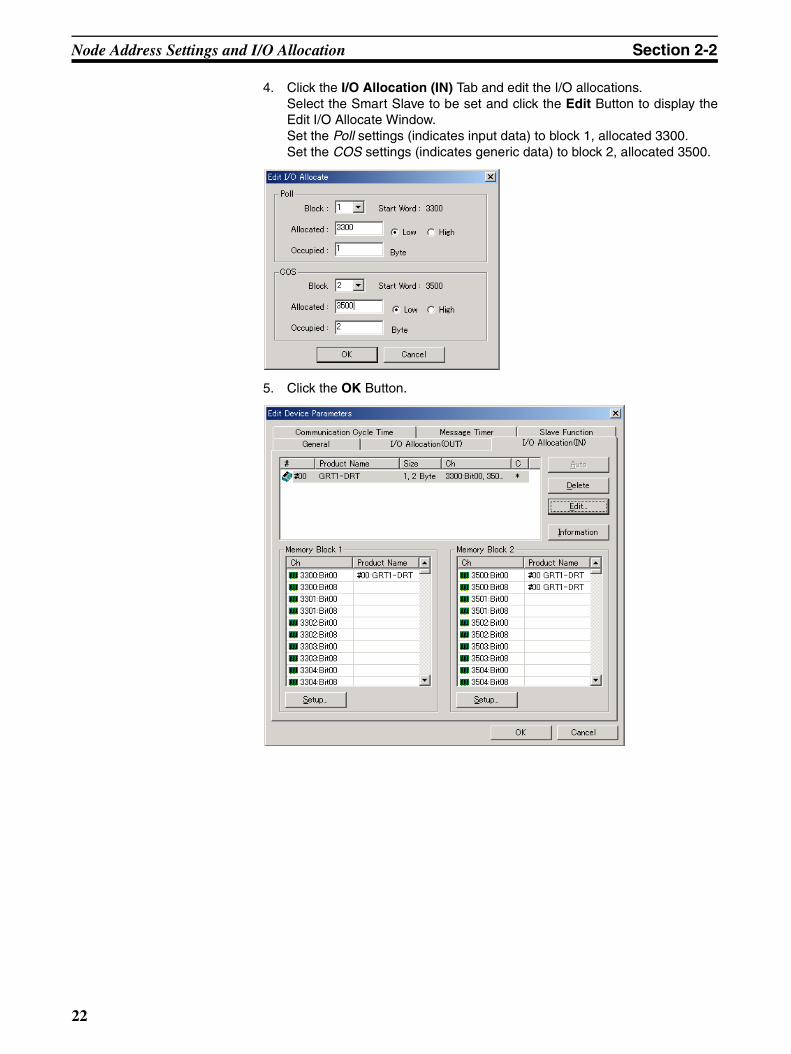
4. Click the I/O Allocation (IN) Tab and edit the I/O allocations.Select the Smart Slave to be set and click the Edit Button to display theEdit I/O Allocate Window.Set the Poll settings (indicates input data) to block 1, allocated 3300.Set the COS settings (indicates generic data) to block 2, allocated 3500.
5. Click the OK Button.
22

Unit Functions Section 2-3
6. In the same way as above, click the I/O Allocation (OUT) Tab and edit theI/O allocations. Set to block 1, allocated 3200.
7. Return to the General Tab Page and click Download.
Note When Auto allocation as is registered. is selected in the General Tab Page,each time the connection path is set, a message will be displayed indicatingthat the current I/O allocations have been deleted because the connectionhas been changed. To set the connection path, deselect Auto allocation as isregistered. before registering the Slaves.
2-3 Unit Functions
Function List The following table lists the DeviceNet Communications Unit’s functions.
Function name Summary Setting/monitoring method
Table registration Reads the configuration of the Slice I/O Units connected to the Communications Unit and registers that information in a table.
Set with DIP switch.
Backup Records the parameter data of all connected I/O Units in the Com-munications Unit.
Set with DIP switch.
Automatic restore Automatically downloads the backed-up parameter data to the appropriate Unit.
Set with DIP switch.
Online replacement I/O Units can be replaced without turning the power OFF. No setting required.
Automatic baud rate recognition
The Master's communications baud rate is automatically detected and adopted.
No setting required.
Network power sup-ply voltage monitor
The DeviceNet network's power supply voltage values are recorded in the DeviceNet Communications Unit.
Set/read with Configurator or explicit message.
Unit power ON time monitor
Records the total time that the DeviceNet Communications Unit's internal circuit power has been ON.
Set/read with Configurator or explicit message.
Unit comment A user-set name can be assigned to the Communications Unit. Set/read with Configurator or explicit message.
Network communi-cations error history
A communications error history from the viewpoint of the Commu-nications Unit can be collected in the Communications Unit.
Set/read with Configurator or explicit message.
23

Unit Functions Section 2-3
2-3-1 Table Registration Function
Function Overview This function registers the configuration of the Slice I/O Units connected to theDeviceNet Communications Unit in a table within the Unit, so that the regis-tered I/O table can be automatically compared with the actual configurationeach time that the power is turned ON. The configuration is registered simplyby turning ON (OFF to ON) pin 1 of the DeviceNet Communications Unit’s DIPswitch while the Slice I/O Terminal’s power supply is ON. The registered tableis enabled if pin 1 is ON when the power is turned ON. If pin 1 is OFF whenthe power is turned ON, the registered table is disabled and the Communica-tions Unit will automatically detect the actual I/O configuration and start com-munications.
Creating a New Registration Table
The Slice I/O Terminal’s present I/O configuration can be read and registeredin the table just by turning DIP switch pin 1 (REGS) from OFF to ON while theDeviceNet Communications Unit’s power supply is ON. If the registration tableis being refreshed, the old registration table will be erased.
Note The configuration information shows the order that the Slice I/OUnits are connected and the I/O size (input or output, number ofbits) of each Slice I/O Unit. The I/O Unit model numbers are not re-corded.
I/O communications error history
A history of communications errors with connected I/O Units can be collected in the Communications Unit.
Set/read with Configurator or explicit message.
Last maintenance date
The date on which maintenance was performed can be written to the Communications Unit.
Set/read with Configurator or explicit message.
Function name Summary Setting/monitoring method
Power ON
Turn pin 1 fromOFF to ON withthe power ON.
Registration table Reads the configuration information, createsthe registration table, and records the table.
4contactinputs
DeviceNet CommunicationsUnit
Figure 1
#1 #2 #3 #4
4contactinputs
4contactoutputs
2relay
outputs
24

Unit Functions Section 2-3
Comparison with the Registered Table
When DIP switch pin 1 (REGS) is ON and an I/O configuration table has beenregistered in the Communications Unit, the actual I/O configuration is auto-matically compared to the registered table when the power is turned ON. Averification error will occur if a registered I/O Unit cannot join I/O communica-tions or an unregistered I/O Unit is detected.
If there are verification errors, the affected Slice I/O Units will not join in I/Ocommunications. I/O communications will start with the other Slice I/O Units.
Example of Comparison between Figure 1 and Figure 2
Note (1) Register the I/O configuration table when all of the Slice I/O Units arecommunicating, i.e., when the DeviceNet Communications Unit’s TS indi-cator is lit green.
(2) A mismatch (verification error) with the registered table is indicated at theDeviceNet Communications Unit’s TS indicator (flashing red) and can beread from the Configurator. The error details can be read from the Con-figurator or the error history can be read with an explicit message com-mand.
#1
#2
#3
#4
#1
#2
#3
#4
From left
Mismatch
I/O
Input
Input
Output
Output
Bits
4
4
4
2
Registered table Actual configuration
From left I/O
Input
Input
Output
Output
Bits
4
4
2
2
There are the same number ofUnits, but the I/O data size does not match, so a verification error occurs and this I/O Unit does notjoin in communications.
#1 #2 #3 #4
Pin 1 ON when powerwas turned ON.
Registration table
The actual configuration is compared to the registered table.Units that do not match the registered table do not participatein I/O communications. I/O communications start with the otherI/O Units.
Fourcontactinputs
Figure 2 Fourcontactinputs
Tworelay
outputs
Tworelay
outputs
DeviceNet CommunicationsUnit
25
Unit Functions Section 2-3
2-3-2 Backup Function
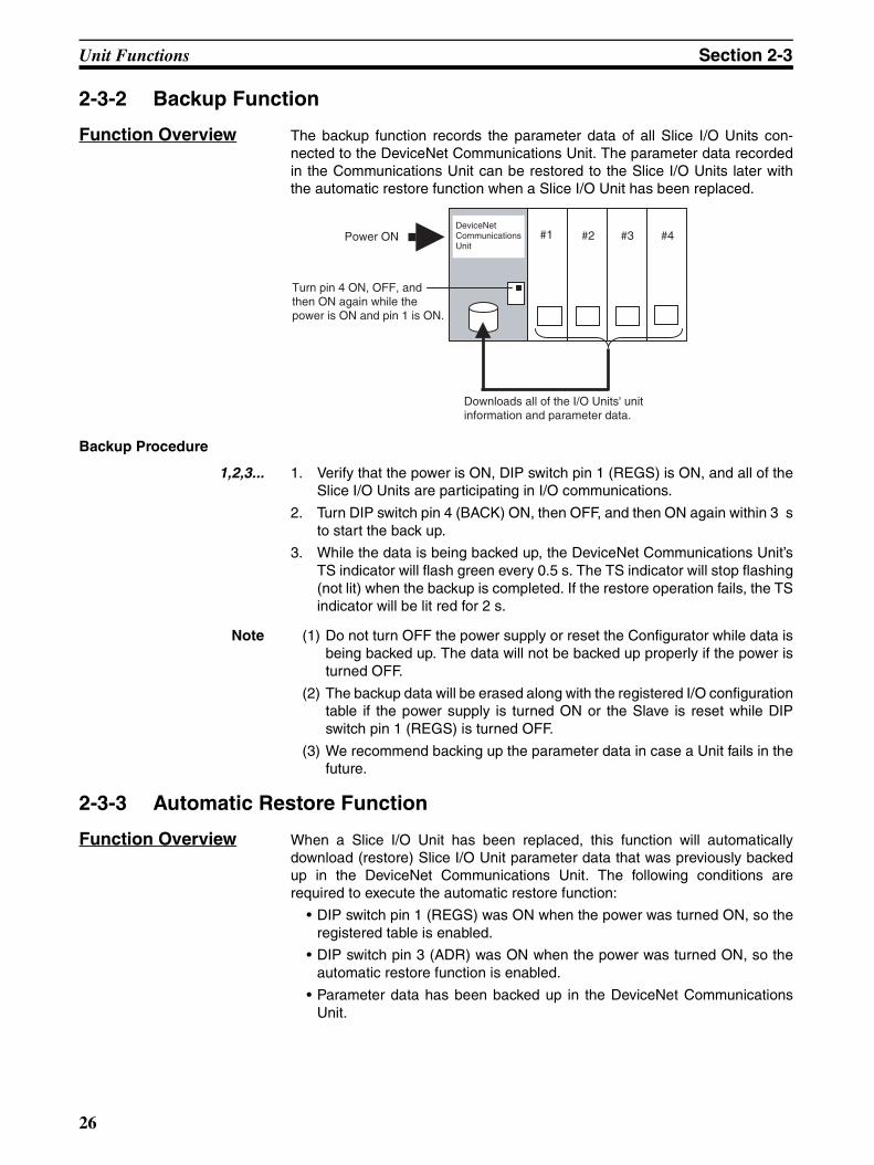
Function Overview The backup function records the parameter data of all Slice I/O Units con-nected to the DeviceNet Communications Unit. The parameter data recordedin the Communications Unit can be restored to the Slice I/O Units later withthe automatic restore function when a Slice I/O Unit has been replaced.
Backup Procedure
1,2,3... 1. Verify that the power is ON, DIP switch pin 1 (REGS) is ON, and all of theSlice I/O Units are participating in I/O communications.
2. Turn DIP switch pin 4 (BACK) ON, then OFF, and then ON again within 3 sto start the back up.
3. While the data is being backed up, the DeviceNet Communications Unit’sTS indicator will flash green every 0.5 s. The TS indicator will stop flashing(not lit) when the backup is completed. If the restore operation fails, the TSindicator will be lit red for 2 s.
Note (1) Do not turn OFF the power supply or reset the Configurator while data isbeing backed up. The data will not be backed up properly if the power isturned OFF.
(2) The backup data will be erased along with the registered I/O configurationtable if the power supply is turned ON or the Slave is reset while DIPswitch pin 1 (REGS) is turned OFF.
(3) We recommend backing up the parameter data in case a Unit fails in thefuture.
2-3-3 Automatic Restore Function
Function Overview When a Slice I/O Unit has been replaced, this function will automaticallydownload (restore) Slice I/O Unit parameter data that was previously backedup in the DeviceNet Communications Unit. The following conditions arerequired to execute the automatic restore function:
• DIP switch pin 1 (REGS) was ON when the power was turned ON, so theregistered table is enabled.
• DIP switch pin 3 (ADR) was ON when the power was turned ON, so theautomatic restore function is enabled.
• Parameter data has been backed up in the DeviceNet CommunicationsUnit.
DeviceNetCommunicationsUnit
Turn pin 4 ON, OFF, andthen ON again while the power is ON and pin 1 is ON.
Downloads all of the I/O Units' unit information and parameter data.
#1 #2 #3 #4Power ON
26
Unit Functions Section 2-3
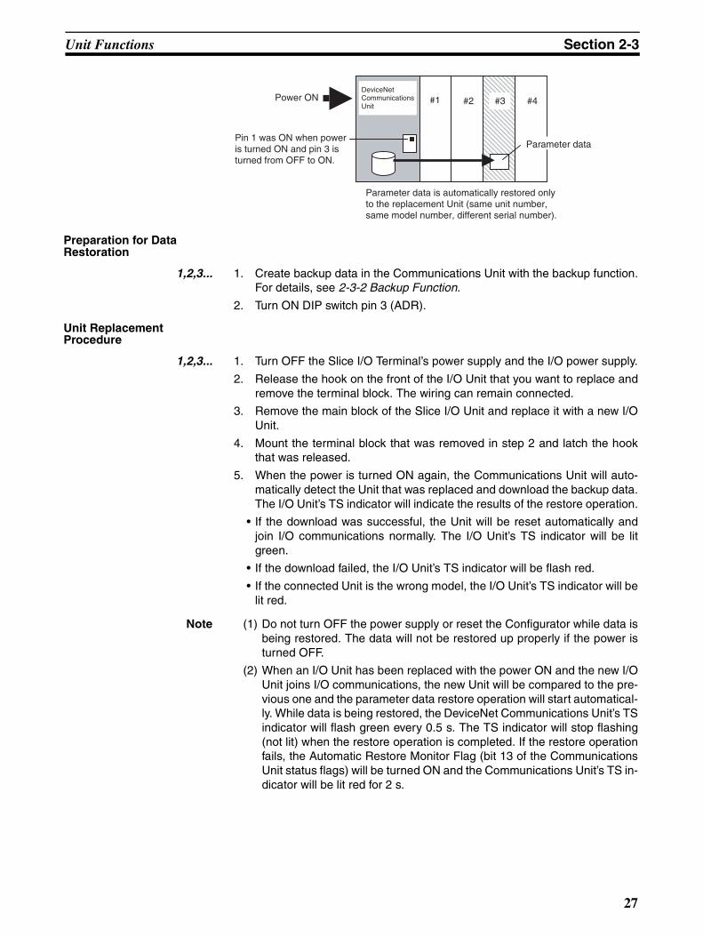
Preparation for Data Restoration
1,2,3... 1. Create backup data in the Communications Unit with the backup function.For details, see 2-3-2 Backup Function.
2. Turn ON DIP switch pin 3 (ADR).
Unit Replacement Procedure
1,2,3... 1. Turn OFF the Slice I/O Terminal’s power supply and the I/O power supply.
2. Release the hook on the front of the I/O Unit that you want to replace andremove the terminal block. The wiring can remain connected.
3. Remove the main block of the Slice I/O Unit and replace it with a new I/OUnit.
4. Mount the terminal block that was removed in step 2 and latch the hookthat was released.
5. When the power is turned ON again, the Communications Unit will auto-matically detect the Unit that was replaced and download the backup data.The I/O Unit’s TS indicator will indicate the results of the restore operation.
• If the download was successful, the Unit will be reset automatically andjoin I/O communications normally. The I/O Unit’s TS indicator will be litgreen.
• If the download failed, the I/O Unit’s TS indicator will be flash red.
• If the connected Unit is the wrong model, the I/O Unit’s TS indicator will belit red.
Note (1) Do not turn OFF the power supply or reset the Configurator while data isbeing restored. The data will not be restored up properly if the power isturned OFF.
(2) When an I/O Unit has been replaced with the power ON and the new I/OUnit joins I/O communications, the new Unit will be compared to the pre-vious one and the parameter data restore operation will start automatical-ly. While data is being restored, the DeviceNet Communications Unit’s TSindicator will flash green every 0.5 s. The TS indicator will stop flashing(not lit) when the restore operation is completed. If the restore operationfails, the Automatic Restore Monitor Flag (bit 13 of the CommunicationsUnit status flags) will be turned ON and the Communications Unit’s TS in-dicator will be lit red for 2 s.
DeviceNetCommunicationsUnit
Pin 1 was ON when poweris turned ON and pin 3 isturned from OFF to ON.
Parameter data is automatically restored onlyto the replacement Unit (same unit number, same model number, different serial number).
Parameter data
Power ON #1 #2 #3 #4
27

Unit Functions Section 2-3
2-3-4 Online Replacement Function
Function Overview When one of the Slice I/O Units connected to the DeviceNet CommunicationsUnit must be replaced, the Unit can be replaced without turning OFF thepower. The Units can be replaced online because the Slice I/O Units aremade up of 3 blocks: the base block, main block, and terminal block. Whenreplacing a Slice I/O Unit, leave just the base block connected and replace themain block. I/O communications will continue with the other I/O Units evenwhile the problem Unit is being removed and replaced.
Replacement Procedure
1,2,3... 1. Turn OFF the I/O power supply of the I/O Unit being replaced.
2. Release the hook on the front of the I/O Unit that you want to replace andremove the terminal block. The wiring can remain connected.
3. Remove the main block of the Slice I/O Unit and replace it with a new I/OUnit.
4. Mount the terminal block that was removed in step 2 and latch the hookthat was released.
5. Turn ON the I/O power supply.
Note (1) When a Unit withdraws from I/O communications during replacement, thecorresponding Slice I/O Unit Communications Withdrawn Flag will go ONand the DeviceNet Communications Unit’s TS indicator will flash red.
(2) Before using the automatic restore function, the preparation for automaticrestoration (creating backup data and turning ON DIP switch pin 3) mustbe completed. See 2-3-3 Automatic Restore Function for details.
(3) Always turn OFF the I/O Unit’s I/O power supply before replacement inorder to prevent false output signals, false input signals, and electricalshocks. In addition, if external power is supplied to the terminal block fora Unit such as a Relay Output Unit, turn OFF that power supply beforereplacing the Unit.
(4) Only replace one I/O Unit at a time.
(5) Always replace the I/O Unit with the same model of I/O Unit. If a Unit isreplaced with a different model, there may be unexpected outputs and therestore operation may not be completed properly.
(6) If the base block is faulty or damaged, turn OFF the power supply and re-place the entire Unit. Even in this case, the I/O Unit’s parameter data willbe restored automatically if the automatic restore function is enabledwhen the power is turned ON.
To keep the system online, leave thecommunications block connected.
Unit beingreplaced
If pin 1 and pin 3 are ON,data is automatically restoredto the replaced Unit.
Power ON
DeviceNetCommunicationsUnit
#1 #2
#3
#4
28

Unit Functions Section 2-3
2-3-5 Automatic Baud Rate RecognitionThe DeviceNet Communications Unit’s baud rate is automatically adjusted tomatch the Master's baud rate. The Communications baud rate is set andsaved after the power is turned ON and communications with the Master areestablished. The baud rate setting is retained until the next time that thepower is turned ON.
Note If the Master’s baud rate has been changed, the DeviceNet CommunicationsUnit must be turned OFF and then ON again to change its baud rate.
2-3-6 Network Power Supply Voltage Monitor
Function Overview The present, bottom, and peak values of the Network power voltage can berecorded in the DeviceNet Communications Unit. A monitor voltage level canbe set with the Configurator and recorded in the DeviceNet CommunicationsUnit. The Network Power Voltage Error Flag in the Status Area will be turnedON when the voltage drops below the set monitor value. The current, mini-mum, and maximum values of the Network power voltage, and the NetworkPower Voltage Error Flag can be read from the Configurator.
Note 1. The communications power voltage of the actual DeviceNet is 11 V mini-mum, so if the communications power voltage drops below 11 V, the oper-ation for reading the measurement values using the Configurator may notfunction properly.
2. The maximum and minimum Network power voltages are cleared when theNetwork power is turned OFF.
Setting Using the DeviceNet Configurator
The method used to set values from the DeviceNet Configurator (Ver. 2.43 orlater) is described here.
1,2,3... 1. Turn ON the DeviceNet Communications Unit’s power supply.
2. From the Main Window, open the Network Configuration Window and dou-ble-click or click the right mouse button over the icon of the DeviceNetCommunications Unit to be set. Select Parameter and Edit to display theEdit Device Parameters Window. From the Maintenance Mode Window, click the right mouse button over theicon of the DeviceNet Communications Unit to be set. Select Parameterand Edit to display the Edit Device Parameters Window.
29
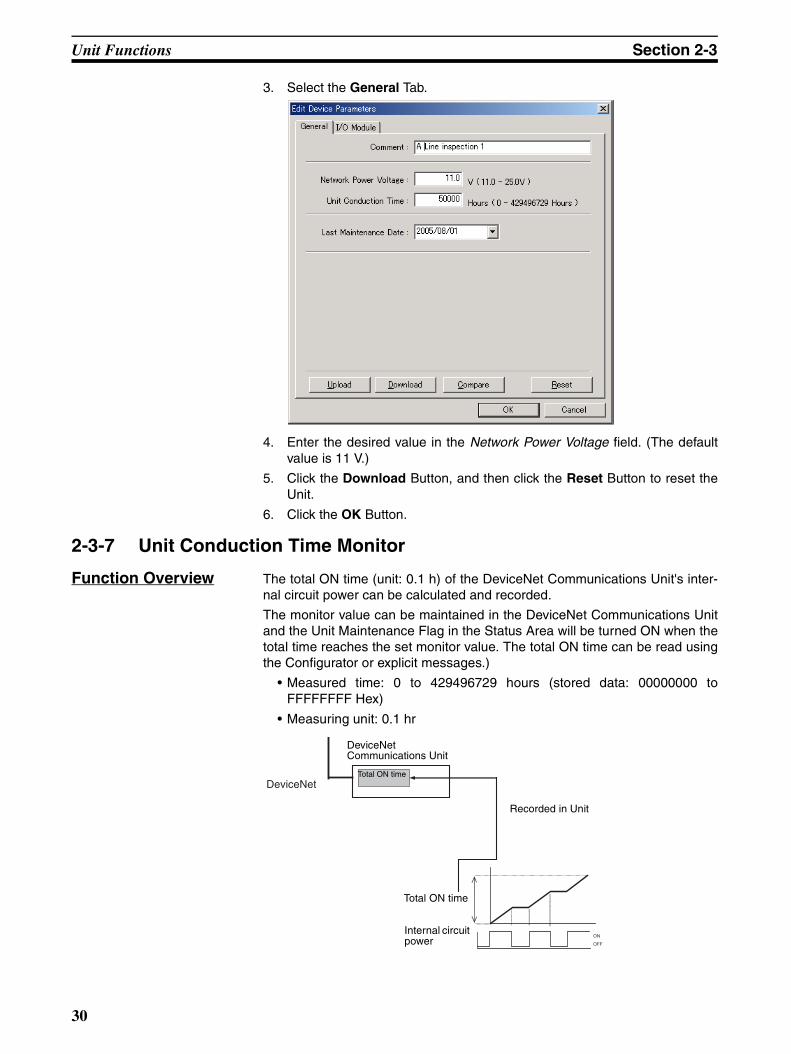
Unit Functions Section 2-3
3. Select the General Tab.
4. Enter the desired value in the Network Power Voltage field. (The defaultvalue is 11 V.)
5. Click the Download Button, and then click the Reset Button to reset theUnit.
6. Click the OK Button.
2-3-7 Unit Conduction Time Monitor
Function Overview The total ON time (unit: 0.1 h) of the DeviceNet Communications Unit's inter-nal circuit power can be calculated and recorded.
The monitor value can be maintained in the DeviceNet Communications Unitand the Unit Maintenance Flag in the Status Area will be turned ON when thetotal time reaches the set monitor value. The total ON time can be read usingthe Configurator or explicit messages.)
• Measured time: 0 to 429496729 hours (stored data: 00000000 toFFFFFFFF Hex)
• Measuring unit: 0.1 hr
ON
OFF
DeviceNet
DeviceNet Communications Unit
Total ON time
Recorded in Unit
Total ON time
Internal circuit power
30

Unit Functions Section 2-3
Note The Unit conduction time monitor (Power ON time monitor) calculates the totaltime that the Smart Slave's Network power supply is ON. The total time is notcalculated when the power is OFF.
Setting Using the DeviceNet Configurator
The method used to set values from the DeviceNet Configurator (Ver. 2.43 orlater) is described here.
1,2,3... 1. Turn ON the DeviceNet Communications Unit's power supply.
2. From the Main Window, open the Network Configuration Window and dou-ble-click or click the right mouse button over the icon of the DeviceNetCommunications Unit to be set. Select Parameter and Edit to display theEdit Device Parameters Window. From the Maintenance Mode Window, click the right mouse button over theicon of the DeviceNet Communications Unit to be set. Select Parameterand Edit to display the Edit Device Parameters Window.
3. Select the General Tab.
4. Enter the desired value in the Unit Conduction Time field.
5. Click the Download Button, and then click the Reset Button to reset theUnit.
6. Click the OK Button.
31

Unit Functions Section 2-3
2-3-8 Unit Comments
Function Overview The user can assign and record a name or comment for every Unit (up to 32characters). The Configurator or explicit messages can be used to read andwrite these Unit names (comments).
Setting Using the DeviceNet Configurator
The method used to set values from the DeviceNet Configurator (Ver. 2.43 orlater) is described here.
Either of the following two settings methods can be used.
Setting Method 1
1,2,3... 1. Turn ON the DeviceNet Communications Unit's power supply.
2. From the Main Window, open the Network Configuration Window and dou-ble-click or click the right mouse button over the icon of the DeviceNetCommunications Unit to be set. Select Parameter and Edit to display theEdit Device Parameters Window. From the Maintenance Mode Window, click the right mouse button over theicon of the DeviceNet Communications Unit to be set. Select Parameterand Edit to display the Edit Device Parameters Window.
3. Select the General Tab.
4. Enter the desired name in the Comment field.
DeviceNet Network
Unit comment (name)Recorded in Unit
Configurator
Unit comment (name)
DeviceNet Communications Unit
What is this Unit used for?
32
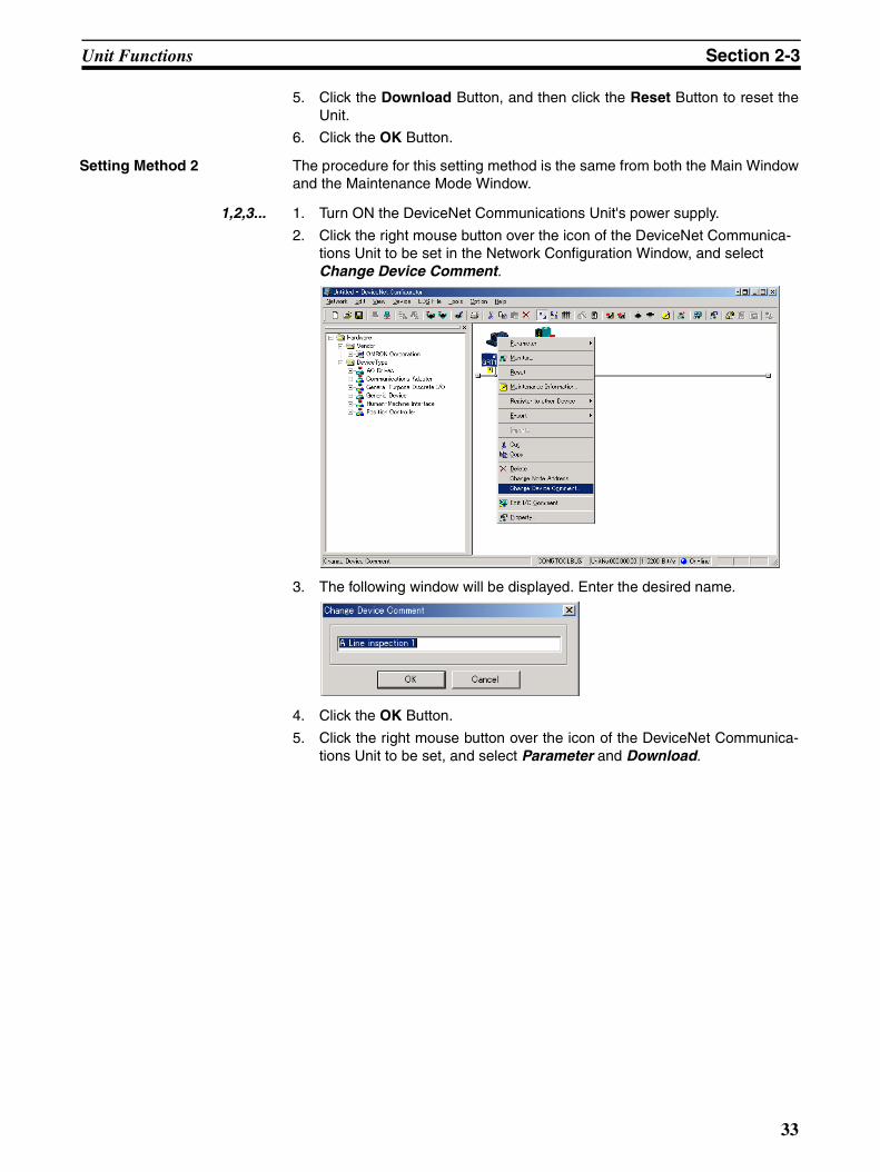
Unit Functions Section 2-3
5. Click the Download Button, and then click the Reset Button to reset theUnit.
6. Click the OK Button.
Setting Method 2 The procedure for this setting method is the same from both the Main Windowand the Maintenance Mode Window.
1,2,3... 1. Turn ON the DeviceNet Communications Unit's power supply.
2. Click the right mouse button over the icon of the DeviceNet Communica-tions Unit to be set in the Network Configuration Window, and select Change Device Comment.
3. The following window will be displayed. Enter the desired name.
4. Click the OK Button.
5. Click the right mouse button over the icon of the DeviceNet Communica-tions Unit to be set, and select Parameter and Download.
33

Unit Functions Section 2-3
2-3-9 Network Communications Error History Monitor
Function Overview The error status information (communications error code, communicationspower voltage when the error occurred) for the last four communicationserrors that occurred between the DeviceNet Communications Unit and Mastercan be recorded in the DeviceNet Communications Unit.
(The Configurator or explicit message commands can be used to read thecommunications error history.)
Checking Using the DeviceNet Configurator
The method used to check error information from the DeviceNet Configurator(Ver. 2.43 or later) is described here.
1,2,3... 1. Turn ON the DeviceNet Communications Unit's power supply.
2. Click the right mouse button over the icon of the DeviceNet Communica-tions Unit to be set in the Network Configuration Window, and select Mon-itor.
DeviceNet Network
DeviceNetCommunications Unit
Error history recordedin the Slave.
What happened to cause a communications error?
Status when communications error occurred
First errorSecond errorThird errorFourth error
34

Unit Functions Section 2-3
3. Select the Error History Tab in the Monitor Device Window. The commu-nications error history for the last four errors that occurred will be dis-played, as shown in the following window. To display the most recent errorhistory, click the Update Button.
Note From the Maintenance Mode Window, double-click the Slave icon, and selectthe Error History Tab from the Maintenance Information Window.
2-3-10 I/O Communications Error History Monitor
Function Overview The DeviceNet Communications Unit can record the 64 most recent Slice I/OTerminal communications errors and internal Communications Unit errors inthe Unit’s error history. When more than 64 errors occur, the oldest entry isdeleted to make space for the newest error entry. The communications errorhistory can be read from the Configurator or explicit message commands.
DeviceNet Network
DeviceNetCommunications Unit
Error logrecordedin Slave.
What happened to cause a communications error?
Status when communications error occurred
1st error
64th error
35

Unit Functions Section 2-3
Checking Using the DeviceNet Configurator
The method used to check error information from the DeviceNet Configurator(Ver. 2.43 or later) is described here.
1,2,3... 1. Turn ON the DeviceNet Communications Unit's power supply.
2. Click the right mouse button over the icon of the DeviceNet Communica-tions Unit to be set in the Network Configuration Window, and select Mon-itor.
3. Select the I/O Unit Error History Tab in the Monitor Device Window. Thecommunications error history for the most recent errors that occurred willbe displayed, as shown in the following window. To display the most recenterror history, click the Update Button.
36

Unit Functions Section 2-3
2-3-11 Last Maintenance Date
Function Overview This function enables the date on which maintenance was last performed tobe written to the Unit. This means that the timing for future maintenance canbe judged more easily. The date can be written using the Configurator.
Setting Using the DeviceNet Configurator
1,2,3... 1. From the Main Window, double-click the icon of the DeviceNet Communi-cations Unit to be set to display the Edit Device Parameters Window. (Fromthe Maintenance Mode Window, click the right mouse button over the iconof the DeviceNet Communications Unit to be set and select Parameter andEdit to display the Edit Device Parameters Window.)
2. Click the General Tab, and select the desired date from the pull-downmenu for the Last Maintenance Date field. (Click the Today Button to enterthe current date.)
3. Click the Download Button, and then click the Reset Button to reset theUnit.
4. Click the OK Button.
37

Unit Functions Section 2-3
38
SECTION 3Installation and Wiring
This section provides information on installing and wiring a Slice I/O Terminal.
3-1 Installation. . . . . . . . . . . . . . . . . . . . . . . . . . . . . . . . . . . . . . . . . . . . . . . . . . . . 40
3-1-1 Connecting the DeviceNet Communications Unit and Slice I/O Unit 40
3-1-2 Connecting Additional Slice I/O Units. . . . . . . . . . . . . . . . . . . . . . . 41
3-1-3 Installation on a DIN Track . . . . . . . . . . . . . . . . . . . . . . . . . . . . . . . 42
3-2 Power Supply Wiring . . . . . . . . . . . . . . . . . . . . . . . . . . . . . . . . . . . . . . . . . . . 44
3-2-1 Connecting the Slice I/O Terminal Power Supply . . . . . . . . . . . . . . 44
3-2-2 Wiring Methods . . . . . . . . . . . . . . . . . . . . . . . . . . . . . . . . . . . . . . . . 45
3-3 Wiring DeviceNet Communications Cables . . . . . . . . . . . . . . . . . . . . . . . . . . 47
3-3-1 Connecting Communications Cables . . . . . . . . . . . . . . . . . . . . . . . . 47
3-3-2 Connecting to the DeviceNet Communications Unit . . . . . . . . . . . . 50
3-4 Connecting the Turnback Cable . . . . . . . . . . . . . . . . . . . . . . . . . . . . . . . . . . . 50
3-4-1 Connecting the Turnback Units . . . . . . . . . . . . . . . . . . . . . . . . . . . . 50
39
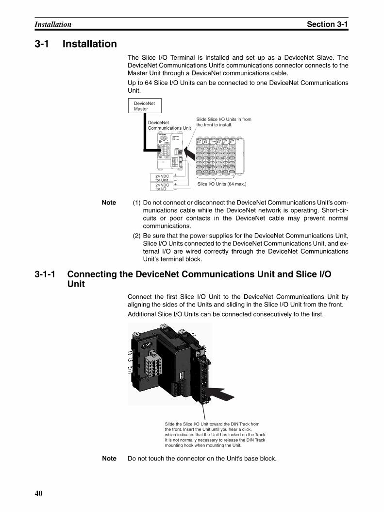
Installation Section 3-1
3-1 InstallationThe Slice I/O Terminal is installed and set up as a DeviceNet Slave. TheDeviceNet Communications Unit’s communications connector connects to theMaster Unit through a DeviceNet communications cable.
Up to 64 Slice I/O Units can be connected to one DeviceNet CommunicationsUnit.
Note (1) Do not connect or disconnect the DeviceNet Communications Unit’s com-munications cable while the DeviceNet network is operating. Short-cir-cuits or poor contacts in the DeviceNet cable may prevent normalcommunications.
(2) Be sure that the power supplies for the DeviceNet Communications Unit,Slice I/O Units connected to the DeviceNet Communications Unit, and ex-ternal I/O are wired correctly through the DeviceNet CommunicationsUnit’s terminal block.
3-1-1 Connecting the DeviceNet Communications Unit and Slice I/O Unit
Connect the first Slice I/O Unit to the DeviceNet Communications Unit byaligning the sides of the Units and sliding in the Slice I/O Unit from the front.
Additional Slice I/O Units can be connected consecutively to the first.
Note Do not touch the connector on the Unit’s base block.
DeviceNetMaster
DeviceNetCommunications Unit
Slide Slice I/O Units in fromthe front to install.
Slice I/O Units (64 max.)
24 VDCfor Unit24 VDCfor I/O
Slide the Slice I/O Unit toward the DIN Track fromthe front. Insert the Unit until you hear a click,which indicates that the Unit has locked on the Track.It is not normally necessary to release the DIN Trackmounting hook when mounting the Unit.
40
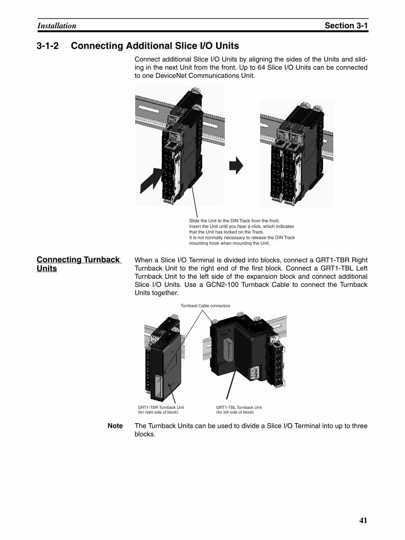
Installation Section 3-1
3-1-2 Connecting Additional Slice I/O UnitsConnect additional Slice I/O Units by aligning the sides of the Units and slid-ing in the next Unit from the front. Up to 64 Slice I/O Units can be connectedto one DeviceNet Communications Unit.
Connecting Turnback Units
When a Slice I/O Terminal is divided into blocks, connect a GRT1-TBR RightTurnback Unit to the right end of the first block. Connect a GRT1-TBL LeftTurnback Unit to the left side of the expansion block and connect additionalSlice I/O Units. Use a GCN2-100 Turnback Cable to connect the TurnbackUnits together.
Note The Turnback Units can be used to divide a Slice I/O Terminal into up to threeblocks.
Slide the Unit to the DIN Track from the front. Insert the Unit until you hear a click, which indicatesthat the Unit has locked on the Track.It is not normally necessary to release the DIN Trackmounting hook when mounting the Unit.
GRT1-TBR Turnback Unit(for right side of block)
Turnback Cable connectors
GRT1-TBL Turnback Unit(for left side of block)
41

Installation Section 3-1
Connecting the End Unit
A GRT1-END End Unit must be connected to the end of the Slice I/O Termi-nal.
3-1-3 Installation on a DIN Track
DIN Track Installation Mount the DeviceNet Communications Unit and Slice I/O Units on a DINTrack. Attach the DIN Track with screws in every fourth mounting hole.
PFP-50N (50 cm) or PFP-100N (100 cm) DIN Track
PFP-M End Plate (Two Required)
GRT1-END End Unit
Attach the track with screws at amaximum spacing of 105 mm between adjacent screws.
42
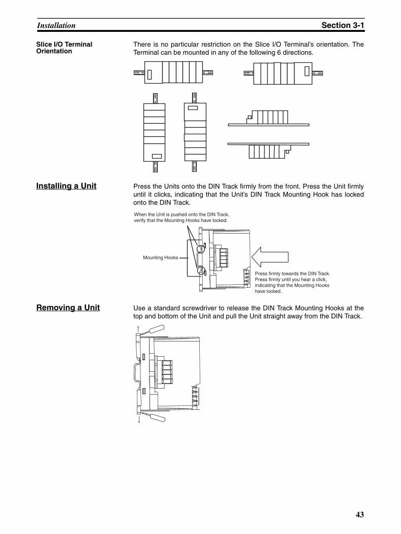
Installation Section 3-1
Slice I/O Terminal Orientation
There is no particular restriction on the Slice I/O Terminal’s orientation. TheTerminal can be mounted in any of the following 6 directions.
Installing a Unit Press the Units onto the DIN Track firmly from the front. Press the Unit firmlyuntil it clicks, indicating that the Unit’s DIN Track Mounting Hook has lockedonto the DIN Track.
Removing a Unit Use a standard screwdriver to release the DIN Track Mounting Hooks at thetop and bottom of the Unit and pull the Unit straight away from the DIN Track.
Press firmly towards the DIN Track.Press firmly until you hear a click,indicating that the Mounting Hookshave locked.
Mounting Hooks
When the Unit is pushed onto the DIN Track,verify that the Mounting Hooks have locked.
43

Power Supply Wiring Section 3-2
Installing the End Plates
Always secure the Slice I/O Terminal on the DIN Track by installing End Plateson both sides of the Terminal. First hook the bottom of the End Plate on thebottom edge of the DIN Track (1), attach the top of the End Plate, and pull theEnd Plate down onto the top edge of the DIN Track (2).
Tighten the End Plate’s securing screw.
Note Always secure the Slice I/O Terminal by attaching End Plates on both ends.
3-2 Power Supply WiringBoth the Slice I/O Terminal power supply and the external I/O power supplyare connected with screwless clamping-type terminals on the DeviceNetCommunications Unit.
3-2-1 Connecting the Slice I/O Terminal Power SupplyThe DeviceNet Communications Unit has two sets of power supply terminalsfor the following two systems.
Evaluating the Power Supply Requirements
Unit Power Supply The maximum power consumption for a Slice I/O Terminal is 80 W per block.
1,2,3... 1. Calculate the power consumption of all of the Slice I/O Units connected tothe DeviceNet Communications Unit.
2. If the power consumption exceeds 80 W, mount a Right Turnback Unit(GRT1-TBR) on the Slice I/O Unit at the point where the power consump-tion is less than 80 W.
3. Connect the 24 VDC Unit power supply to the Left Turnback Unit (GRT1-TBL).
1
2
End Unit
End PlateEnd Plate
Power supply terminals
Description
Unit power supply terminals
These terminals supply power to the DeviceNet Communica-tions Unit’s internal circuits as well as the connected Slice I/O Units’ internal circuits (supplied through the Slice bus).
I/O power supply ter-minals
These terminals supply power to the external I/O that is con-nected to the Terminal’s Slice I/O Units.
44
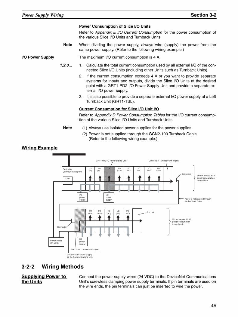
Power Supply Wiring Section 3-2
Power Consumption of Slice I/O Units
Refer to Appendix E I/O Current Consumption for the power consumption ofthe various Slice I/O Units and Turnback Units.
Note When dividing the power supply, always wire (supply) the power from thesame power supply. (Refer to the following wiring example.)
I/O Power Supply The maximum I/O current consumption is 4 A.
1,2,3... 1. Calculate the total current consumption used by all external I/O of the con-nected Slice I/O Units (including other Units such as Turnback Units).
2. If the current consumption exceeds 4 A or you want to provide separatesystems for inputs and outputs, divide the Slice I/O Units at the desiredpoint with a GRT1-PD2 I/O Power Supply Unit and provide a separate ex-ternal I/O power supply.
3. It is also possible to provide a separate external I/O power supply at a LeftTurnback Unit (GRT1-TBL).
Current Consumption for Slice I/O Unit I/O
Refer to Appendix D Power Consumption Tables for the I/O current consump-tion of the various Slice I/O Units and Turnback Units.
Note (1) Always use isolated power supplies for the power supplies.
(2) Power is not supplied through the GCN2-100 Turnback Cable. (Refer to the following wiring example.)
Wiring Example
3-2-2 Wiring Methods
Supplying Power to the Units
Connect the power supply wires (24 VDC) to the DeviceNet CommunicationsUnit’s screwless clamping power supply terminals. If pin terminals are used onthe wire ends, the pin terminals can just be inserted to wire the power.
I/O (AD)
I/O (AD)
I/O (AD)
I/O (IN)
I/O (IN)
I/O (OUT)
I/O (OUT)
I/O (OUT)
CPU
I/O (OUT)
I/O (OUT)
I/O (AD)
I/O (AD)
I/Opowersupply
GRT1-PD2 I/O Power Supply Unit
End Unit
Connector
Power is not supplied throughthe Turnback Cable.
DeviceNetCommunications Unit
Power supply(24 VDC)
GRT1-TBR Turnback Unit (Right)
Do not exceed 80 Wpower consumptionin one block.
I/Opowersupply
I/Opowersupply
Connector
GRT1-TBL Turnback Unit (Left)
Do not exceed 80 Wpower consumptionin one block.
Use the same power supply as the Communications Unit.
45

Power Supply Wiring Section 3-2
Note The GRT1-TBL Left Turnback Unit has the same screwless clamping powersupply terminals. Those terminals are wired in the same way as theDeviceNet Communications Unit’s terminals, just by inserting the power sup-ply wires.
Supplying I/O Power The power supply for I/O devices is supplied through the DeviceNet Commu-nications Unit’s screwless clamping power supply terminals. If pin terminalsare used on the wire ends, the pin terminals can just be inserted to wire thepower.
Note The GRT1-TBL Left Turnback Unit and GRT1-PD2 I/O Power Supply Unithave the same screwless clamping power supply terminals. Those terminalsare wired in the same way as the DeviceNet Communications Unit’s terminals,just by inserting the power supply wires.
Removing Wires Press the release button above the terminal hole with a slotted precisionscrewdriver and pull out the wire.
Use the following screwdriver or an equivalent to remove the wires.
Recommended Screwdriver
These terminals supply power to boththe DeviceNet Communications Unit'sinternal circuits and the connectedSlice I/O Units' internal circuits.
Holes for wires(pin terminals)
Release buttonPress the release button with a screwdriverand pull out the wire (pin terminal).
24 VDC
These terminals supply power to theexternal I/O devices connected to theSlice I/O Units.
Holes for wires(pin terminals)
Release buttonPress the release button with a screwdriverand pull out the wire (pin terminal).
24 VDC
Model Maker
SZF1 Phoenix Contact
Slotted precision screwdriver
Release button
46

Wiring DeviceNet Communications Cables Section 3-3
Recommended Power Supplies
Use a SELV power supply with overcurrent protection.
A SELV power supply has redundant or increased insulation between the I/O,an output voltage of 30 Vr.m.s and a 42.4-V peak or maximum of 60 VDC.
Recommended power supply: S82K-10024 (OMRON) or S8J-10024D(OMRON)
Recommended Wire
Strip Length Strip between 7 and 10 mm of insulation at the ends of the wires (stranded orsolid wire).
Pin Terminal Length Use pin terminals with a pin (conductor) length of 8 to 10 mm.
3-3 Wiring DeviceNet Communications CablesThis section explains how to prepare the DeviceNet communications cablesthat connect to the DeviceNet Communications Unit and how to attach com-munications connectors.
For details on supplying the DeviceNet communications power and groundingthe DeviceNet Network, refer to the DeviceNet Operation Manual (W267).
3-3-1 Connecting Communications Cables Use the following procedure to prepare the communications cables and con-nect them to the connectors.
The same methods are used to connect the cables to connectors with andwithout set screws.
1,2,3... 1. Remove about 30 to 80 mm of the cable covering, being careful not to dam-age the mesh shield underneath. Do not remove more than necessary. Re-moving excessive cable covering may cause a short-circuit.
3.5 mm0.6 mm
Side view Front view
Type Gauge
Stranded wire 20 AWG to 16 AWG(0.5 to 1.25 mm2)Solid wire
Pin terminal
Strip 7 to 10 mm.
Pin length: 8 to 10 mm
About 30 to 80 mm (Remove as little as possible.)
47

Wiring DeviceNet Communications Cables Section 3-3
2. Peel back the mesh shield carefully to expose the signal lines, power lines,and the shielding wire. The shielding wire will be loose on the outside ofthe other lines, but it is harder than the mesh shield and should be easilyidentified.
3. Remove the exposed mesh shield, remove the aluminum tape from the sig-nal and power lines, and strip the covering from the signal and power linesto the proper length for the crimp terminal connectors. Twist together thewires of each of the signal and power lines.
4. Attach the crimp terminals to the lines and then cover any exposed areasof the cable and lines with electrician's tape or heat-shrinking tubes. Orient the connector properly, loosen the line set screws, and then insertthe lines in order: Red, white, shield, blue, and then black. The DeviceNet Communications Unit is equipped with screwless clampingterminals. It is not necessary to secure the lines with screws as with previ-ous connectors. Push up the orange tab and then insert each line into theback of each hole. Release the orange lever after inserting the lines, and gently pull each lineto check that it is securely connected to the connector.
There are colored stickers provided on the Master Unit and Slaves thatmatch the colors of the lines to be inserted. Check that the colors of thelines and stickers match when wiring the connectors.
The colors used are as follows:
Color Signal
Red Power line, positive voltage (+V)
White Communications line, high (CAN H)
- Shield
Blue Communications line, low (CAN L)
Black Power line, negative voltage (−V)
Shield wire
Strip to match the crimp terminals.
Red (+V)White (CAN H)
Shield
Black (−V)
Blue (CAN L)
48

Wiring DeviceNet Communications Cables Section 3-3
The following connector is included with the Unit.
Note GRT1-DRT Connector CompatibilityThe following table classifies connectors in terms of compatibility with theGRT1-DRT. Before using any connectors other than those shown here, checkfor incompatibility related to structure or cables.
• Compatible Connectors
• Incompatible Connectors
• The following crimp terminals are recommended.Phoenix Contact AI Series and A1 Series
Model Specifications Remarks
XW4G-05C4-TF-D Multi-branch Parallel Clamp Connector with Screws
Provided with Unit.
Model Specifications Remarks
XW4B-05C1-H1-D Parallel Connector with ScrewsFor node and T-branch tap connec-tion. Connector screws provided.
---
XW4B-05C1-VIR-D Orthogonal Connector with Screws
For node and T-branch tap connec-tion. Connector screws provided.
The cable comes out of the left side when viewed from the front of the Unit.
XW4G-05C1-H1-D Parallel Clamp Connector with ScrewsFor node and T-branch tap connec-tion. Connector screws provided.
---
XW4G-05C4-TF-D Multi-branch Parallel Clamp Connec-tor with ScrewsFor multi-drop node connection. Con-nector screws provided.
Provided with Unit.
Model Specifications Remarks
XW4B-05C4-TF-D Multi-branch Parallel Connector with Screws
---
XW4B-05C4-T-D Multi-branch Parallel Connector without Screws
Connector typeCable type
XW4B-05C1-H1-DXW4B-05C1-V1R-D
XW4G-05C1-H1-DXW4G-05C4-TF-D
Crimp tool
Thin Cable
Signal line AI 0.25-6YE AI 0.25-8YE CRIMPFOXZA3 or CRIMPFOXUD6
Power line AI 0.5-6WH AI 0.5-10WH
Thick Cable
Signal line A1-6 A1-10
Power line AI 2.5-8BU AI 2.5-10BU
49

Connecting the Turnback Cable Section 3-4
3-3-2 Connecting to the DeviceNet Communications UnitAlign the DeviceNet Communications Unit connector with the cable connector,and insert the cable connector fully into the DeviceNet Communications Unitconnector.
Always tighten the connector’s screws to a torque between 0.25 and 0.3 N-mto secure the connector.
3-4 Connecting the Turnback CableWhen a Slice I/O Terminal is divided into blocks to expand the system, con-nect a GRT1-TBR Right Turnback Unit to the GRT1-TBL Left Turnback Unitwith a GCN2-100 Turnback Cable.
Note Power is not supplied through the GCN2-100 Turnback Cable. Always wire(supply) the power to the GRT1-TBL Left Turnback Unit from the same powersupply that supplies the DeviceNet Communications Unit.
3-4-1 Connecting the Turnback UnitsConnect the Turnback Units with a Turnback Cable, as shown in the followingdiagram. A single DeviceNet Communications Unit can be expanded with upto two additional blocks, connected with two sets of Turnback Units.
DeviceNetCommunications Unit
GRT1-TBR Turnback Unit
GRT1-TBL Turnback Unit
GCN2-100 Turnback CableInsert the cable's connector fullyuntil it clicks, which indicates thatthe connector's top and bottomlatches have locked.
50

SECTION 4Setup and Operating Procedures
This section outlines the basic procedures for setting up and operating the DeviceNet Communications Unit.
4-1 Basic Operating Procedure and Example Configuration . . . . . . . . . . . . . . . . 52
4-1-1 Basic Operating Procedure . . . . . . . . . . . . . . . . . . . . . . . . . . . . . . . . 52
4-1-2 Example System Configuration . . . . . . . . . . . . . . . . . . . . . . . . . . . . 53
4-2 Preparation for Operation . . . . . . . . . . . . . . . . . . . . . . . . . . . . . . . . . . . . . . . . 53
4-2-1 Determining the Slice I/O Terminal’s I/O Specifications . . . . . . . . . 53
4-2-2 Selecting the Slice I/O Units. . . . . . . . . . . . . . . . . . . . . . . . . . . . . . . 53
4-2-3 Confirming Specifications . . . . . . . . . . . . . . . . . . . . . . . . . . . . . . . . 53
4-2-4 Determining the DeviceNet Network Wiring Method . . . . . . . . . . . 54
4-2-5 Determining the Communications Power Supply Method . . . . . . . . 54
4-3 Setting and Wiring Hardware . . . . . . . . . . . . . . . . . . . . . . . . . . . . . . . . . . . . . 55
4-3-1 Mounting and Setting the Master Unit . . . . . . . . . . . . . . . . . . . . . . . 55
4-3-2 Mounting and Setting the Slice I/O Terminal. . . . . . . . . . . . . . . . . . 55
4-3-3 Connecting Cables . . . . . . . . . . . . . . . . . . . . . . . . . . . . . . . . . . . . . . 57
4-4 Starting Communications . . . . . . . . . . . . . . . . . . . . . . . . . . . . . . . . . . . . . . . . 57
4-4-1 Creating I/O Tables for the Master Unit . . . . . . . . . . . . . . . . . . . . . . 57
4-4-2 Starting the System. . . . . . . . . . . . . . . . . . . . . . . . . . . . . . . . . . . . . . 58
4-4-3 Creating and Registering Scan Lists. . . . . . . . . . . . . . . . . . . . . . . . . 58
4-5 Checking Operation . . . . . . . . . . . . . . . . . . . . . . . . . . . . . . . . . . . . . . . . . . . . 60
4-5-1 Indicator Status . . . . . . . . . . . . . . . . . . . . . . . . . . . . . . . . . . . . . . . . . 60
4-5-2 Checking I/O Communications . . . . . . . . . . . . . . . . . . . . . . . . . . . . 60
51
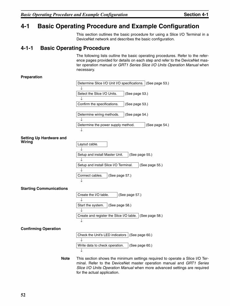
Basic Operating Procedure and Example Configuration Section 4-1
4-1 Basic Operating Procedure and Example ConfigurationThis section outlines the basic procedure for using a Slice I/O Terminal in aDeviceNet network and describes the basic configuration.
4-1-1 Basic Operating ProcedureThe following lists outline the basic operating procedures. Refer to the refer-ence pages provided for details on each step and refer to the DeviceNet mas-ter operation manual or GRT1 Series Slice I/O Units Operation Manual whennecessary.
Preparation
Setting Up Hardware and Wiring
Starting Communications
Confirming Operation
Note This section shows the minimum settings required to operate a Slice I/O Ter-minal. Refer to the DeviceNet master operation manual and GRT1 SeriesSlice I/O Units Operation Manual when more advanced settings are requiredfor the actual application.
Determine Slice I/O Unit I/O specifications. (See page 53.)
↓Select the Slice I/O Units. (See page 53.)
↓Confirm the specifications. (See page 53.)
Determine wiring methods. (See page 54.)
↓Determine the power supply method. (See page 54.)
↓
Layout cable.
↓Setup and install Master Unit. (See page 55.)
↓Setup and install Slice I/O Terminal. (See page 55.)
↓Connect cables. (See page 57.)
↓
Create the I/O table. (See page 57.)
↓Start the system. (See page 58.)
↓Create and register the Slice I/O table. (See page 58.)
↓
Check the Unit’s LED indicators (See page 60.)
↓Write data to check operation. (See page 60.)
↓
52

Preparation for Operation Section 4-2
4-1-2 Example System ConfigurationThis section explains the operating procedure for the following minimal sys-tem configuration. Connect the communications cable between the DeviceNetMaster Unit and DeviceNet Communications Unit after connecting the desiredSlice I/O Units to the DeviceNet Communications Unit.
4-2 Preparation for Operation
4-2-1 Determining the Slice I/O Terminal’s I/O SpecificationsA single GRT1-DRT DeviceNet Communications Unit can control up to 64Slice I/O Units with up to 1,024 I/O bits (64 words). In this example the Slice I/O Terminal has the following configuration.
• 16 inputs
• 16 outputs
4-2-2 Selecting the Slice I/O UnitsThe following devices were selected, as shown in the basic system configura-tion in 4-1-2 Example System Configuration.
Master Unit: CS1W-DRM21-V1DeviceNet Communications Unit: GRT1-DRT1Slice I/O Units: Four GRT1-ID4, four GRT1-OD4, and one GRT1-END
Note OMRON has a wide variety of DeviceNet compatible Master Units and SlaveUnits available. Select the best Units for your application.
4-2-3 Confirming SpecificationsNumber of I/O Points Less Than 1,024 (64 Words)
Verify that the total number of I/O points is less than the maximum of 1,024points (64 words). This example uses the following calculation:
4 Units × 4 inputs (16 points) + 4 Units × 4 outputs (16 points) = 32 points
Power Consumption Less Than 80 W/Block
Verify that the power consumption is less than 80 W per block. This exampleuses the following calculation:
1 GRT1-DRT Unit × 3 W = 3 W4 GRT1-ID4 Units × 1 W = 4 W4 GRT1-OD4 Units × 1 W = 4 WTotal = 11 W
DeviceNet
GRT1-DRT DeviceNetCommunications Unit
Slice I/O Terminal
GRT1-ENDEnd Unit
DeviceNet Configurator
CS1W-DRM21-V1DeviceNet Master Unit
GRT1-ID4 GRT1-OD4
53

Preparation for Operation Section 4-2
Note If the total power consumption of the Slice I/O Units connected to theDeviceNet Communications Unit exceeds 80 W, divide the Slice I/O Terminalinto blocks with Turnback Units and supply power to the added block throughthe GRT1-TBL Left Turnback Unit.
4-2-4 Determining the DeviceNet Network Wiring MethodEither thin cable or thick cable can be used in a DeviceNet network.
The cables can be branched freely using either T-branch Taps or multi-dropconnections.
The maximum network length and total branch line length depend on thebaud rate and type of cable used. For details on network configurations andspecifications, refer to the DeviceNet Operation Manual (W267).
Note Use the OMRON Connectors shown below when using Thick Cables andmulti-drop connections.
XW4G-05C4-TF-D (With connector screws)
4-2-5 Determining the Communications Power Supply MethodEach node in the DeviceNet network (Master Unit and DeviceNet Communi-cations Unit) must be supplied with a 24 V DC power supply for properDeviceNet communications. The communications power, however, can besupplied by communications cables and does not require separate wiring.
I/O (AD)
I/O (AD)
I/O (AD)
I/O (IN)
I/O (IN)
I/O (OUT)
I/O (OUT)
I/O (OUT)
CPU
I/O (OUT)
I/O (OUT)
I/O (AD)
I/O (AD)
I/Opowersupply
GRT1-PD2 I/O Power Supply Unit
End Unit
Connector
Power is not supplied throughthe Turnback Cable.
DeviceNetCommunications Unit
Power supply(24 VDC)
GRT1-TBR Turnback Unit (Right)
Do not exceed 80 Wpower consumptionin one block.
I/Opowersupply
I/Opowersupply
Connector
GRT1-TBL Turnback Unit (Left)
Do not exceed 80 Wpower consumptionin one block.
Use the same power supply as the Communications Unit.
54

Setting and Wiring Hardware Section 4-3
For details on methods of supplying communications power, refer to theDeviceNet Operation Manual (W267).
4-3 Setting and Wiring Hardware4-3-1 Mounting and Setting the Master Unit
The following diagrams show the component names and functions of theCS1W-DRM21, CS1W-DRM21-V1 or CJ1W-DRM21 Master Units, which canbe mounted to a CS/CJ-series PLC. For details on Master Unit settings, referto the DeviceNet CS/CJ Series Units Operation Manual (W380).
CS1W-DRM21 (-V1) The Master Unit is mounted to the Backplane of the PLC in the same way asother Units are normally mounted.
CJ1W-DRM21 The Master Unit does not connect to a Backplane. The Units connect togetherby joining the connectors on the sides.
Note For details on mounting Master Units to PLCs, and mounting PLCs to controlpanels, refer to the applicable PLC operation manual.
4-3-2 Mounting and Setting the Slice I/O Terminal
Setting the DeviceNet Communications Unit
Use the following flowchart when setting the DeviceNet Communications Unitaccording to the requirements of the application. For details on setting theUnit, refer to SECTION 2 Component Names and Functions.
Indicators
Unit number switchThis rotary switch sets the Unit's one-digit hexadecimal unit number in the PLC.
Node address switchesThese rotary switches set the two-digit decimal node address of the Unit.DIP switchPins 1 and 2: Baud ratePin 3: Continue/stop remote I/O communications for errors (for Master function).Pin 4: Hold/clear I/O for communications error (for Slave function).
Communications connectorThis connector is connected to the Network communications cable. Communications power is also supplied through this connector.An XW4B-05C1-H1-D Parallel Connector with Screws is provided asthe node connector.
IndicatorsUnit number switchThis rotary switch sets the Unit's one-digit hexadecimal unit number in the PLC.
Node address switchesThese rotary switches set the two-digit decimal node address of the Unit.DIP switchPins 1 and 2: Baud ratePin 3: Continue/stop remote I/O communications for errors (for Master function).Pin 4: Hold/clear I/O for communications error (for Slave function).Communications connectorThis connector is connected to the Network communications cable. Communications power is also supplied through this connector. An XW4B-05C1-H1-D Parallel Connector with Screws is provided as the node connector.
55
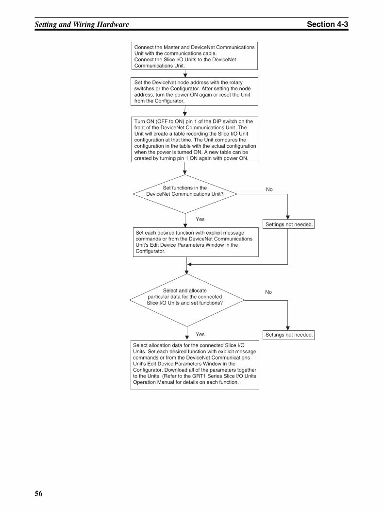
Setting and Wiring Hardware Section 4-3
Settings not needed.
No
No
Yes
Yes
Connect the Master and DeviceNet CommunicationsUnit with the communications cable.Connect the Slice I/O Units to the DeviceNetCommunications Unit.
Set the DeviceNet node address with the rotaryswitches or the Configurator. After setting the nodeaddress, turn the power ON again or reset the Unitfrom the Configurator.
Turn ON (OFF to ON) pin 1 of the DIP switch on thefront of the DeviceNet Communications Unit. TheUnit will create a table recording the Slice I/O Unitconfiguration at that time. The Unit compares theconfiguration in the table with the actual configurationwhen the power is turned ON. A new table can becreated by turning pin 1 ON again with power ON.
Set functions in theDeviceNet Communications Unit?
Set each desired function with explicit messagecommands or from the DeviceNet CommunicationsUnit's Edit Device Parameters Window in theConfigurator.
Select and allocateparticular data for the connectedSlice I/O Units and set functions?
Settings not needed.
Select allocation data for the connected Slice I/OUnits. Set each desired function with explicit messagecommands or from the DeviceNet CommunicationsUnit's Edit Device Parameters Window in theConfigurator. Download all of the parameters togetherto the Units. (Refer to the GRT1 Series Slice I/O UnitsOperation Manual for details on each function.
56

Starting Communications Section 4-4
Mounting the Slice I/O Terminal
Slice I/O Terminals are mounted on to a DIN Track, as shown in the followingdiagram. Secure the bottom of the Terminal to the 35-mm DIN Track. Also,always secure the Terminal to the track between two End Plates.
4-3-3 Connecting Cables
Connecting Communications Cables
Use the following procedure when connecting the cables. For details, refer to5-2 Connecting Communications Cables in the DeviceNet DRT2 SeriesSlaves Operation Manual (W404).
1. Assemble the communications cables.Prepare the communications cables and attach the connectors to the ca-bles.
2. Connect the cables to the nodes.Connect the communications cable connectors to the node connectors onthe Master Unit, T-branch Taps, and DeviceNet Communications Unit.
Wiring the Unit Power Supply
Crimp pin terminals to the Unit power supply cable. Connect the cable to theDeviceNet Communications Unit’s screwless clamping terminals that supplythe DeviceNet Communications Unit’s internal circuits and the connectedSlice I/O Units’ internal circuits.
Wiring the I/O Power Supply
Crimp pin terminals to the I/O power supply cable. Connect the cable to theDeviceNet Communications Unit’s screwless clamping terminals that providethe I/O power supply for I/O devices connected to the Slice I/O Units.
Wiring I/O Crimp pin terminals to the I/O signal lines. Connect the I/O signal lines to theSlice I/O Units connected to the DeviceNet Communications Unit.
4-4 Starting Communications After setting and wiring the hardware, turn ON the communications powersupply, the internal power supply of each node, and the I/O power supply, andthen start communications using the following procedure.
4-4-1 Creating I/O Tables for the Master Unit I/O tables must be created in the CPU Unit to distinguish between the differentSlaves mounted to the PLC. Turn ON the PLC to which the Master Unit ismounted, connect the Peripheral Devices to the PLC, and create the I/Otables. After the I/O tables have been created, turn OFF the power to the PLC.
End Unit
End PlateEnd Plate
57

Starting Communications Section 4-4
The following example shows the procedure for creating I/O tables using aProgramming Console. For details on creating I/O tables, refer to the opera-tion manual for the Peripheral Device being used.
4-4-2 Starting the System Turn ON the communications power supply and the power to other nodes inthe following order.
1,2,3... 1. Turn ON the communications power supply.
2. Turn ON the power to the DeviceNet Communications Unit.
3. Turn ON the power to the Master Unit.
Note The power supplies listed above can all be turned ON simultaneously. Theexternal I/O power supply can be turned ON at any time.
4-4-3 Creating and Registering Scan Lists Scan lists are lists that register the information that is transferred betweenMaster Units and Slaves. The Master Unit compares the scan list with the sta-tus of the Slave currently being communicated with, so communications withthe Slave are always being checked.
PROGRAM
000000 CT00
CH*DM
9 7 1 3
0
00000IOTBL WRIT
OK
<PROGRAM>
PASSWORD!
00000IOTBL ?
?-?U=
00000IOTBL WRIT
????
00000IOTBL WRIT
9713
CLR MONTR CLR
FUN SHIFT
CHG
WRITE
WRITE
CLR
Turn ON the power to the Master Unit
Switch the CPU Unit of the Master Unit to PROGRAM mode.
58

Starting Communications Section 4-4
For details on scan lists and remote I/O communications, refer to theDeviceNet master operation manual.
Note When a scan list is disabled, communications are possible with all Slaves onthe DeviceNet Network with fixed allocations. Without scan lists, however, theMaster Unit cannot check if there is an error in a Slave. For normal operations, always enable the scan lists.
Precautions
User I/O Allocations The user can allocate any words for Slave I/O for the DeviceNet I/O Areas (INArea, OUT Area) in the Master Unit.
When user allocations are used, scan lists must be created with a DeviceNetConfigurator and registered in the Master Unit. The scan list is enabled assoon as it is registered, and remote I/O communications start according to thescan list.
For details, refer to the DeviceNet Operation Manual (W267) and theDeviceNet Configurator Operation Manual (W328).
Fixed I/O Allocations Slave I/O is allocated in the DeviceNet I/O area (IN Area, OUT Area) in theMaster Unit in the same order as the Slave node addresses.
When fixed allocations are used, the scan lists are automatically created andregistered using the Master Unit's software switches. The scan list is enabledas soon as it is registered, and remote I/O communications start according tothe scan list. When scan list is enabled, the mode is called the scan list-enabled mode.
The registered scan lists can be cleared using the software switches. Whenscan lists are cleared (disabled), the mode is called the scan list-disabledmode.
Creating and Registering Fixed Allocation Scan Lists
The method of creating and registering scan lists for fixed allocation usingProgramming Console and a CS/CJ-series Master Unit is explained here. Fordetails on operating Programming Devices, refer to the operation manual forthe Programming Device being used with the PLC. For details on creatingscan lists, refer to the DeviceNet master operation manual.
Creating and Registering Scan Lists
Use the following procedure to create, register, and enable the scan lists.
In the following example, n = 1500 + (25 × unit number).
Clearing and Creating Scan Lists
1,2,3... 1. Switch the PLC’s operating mode to PROGRAM mode.
2. Enable the Master Unit functions. Set the Master Unit function enableswitch (bit 06 of word n) from OFF to ON.
3. Clear the scan lists. Set the scan list clear switch (bit 01 of word n) fromOFF to ON.
4. Select the fixed allocation areas 1 to 3. Set the Master Unit's setting switchfor fixed allocation areas 1 to 3 (bit 00 of word n) from OFF to ON.
5. Enable the scan lists. Set the scan list enable switch (bit 00 of word n) fromOFF to ON.
6. Switch the operating mode switch to RUN or MONITOR mode.
Checking the Normal Slave Table
Monitor the normal Slave table and check that the corresponding bits are ON.In the normal Slave table, the corresponding bits will turn ON for the nodesthat are communicating normally.
59

Checking Operation Section 4-5
4-5 Checking OperationUse the procedures provided here to check that I/O communications are oper-ating normally.
4-5-1 Indicator Status I/O communications are operating normally if the MS and NS indicators for allnodes are lit green, and the 7-segment indicator on the front panel of the Mas-ter Unit is displaying the node address of the Master Unit as shown in the fol-lowing diagram (when the Master Unit's node address is 00), and the scan listis enabled.
4-5-2 Checking I/O CommunicationsConnect the Programming Device for the PLC to the Master Unit, write theMaster Unit's OUT Area and read the IN Area, and check that the data are thesame in the Slaves.
Refer to the DeviceNet master operation manual for details on OUT Area andIN Area addresses and how to allocate Slave I/O.
Operating the Slice I/O Terminal’s I/O Devices
Create the following ladder program in the PLC of the Master Unit, and checkthat the indicator on the GRT1-OD4 Output Unit goes ON when the switch onthe GRT1-ID4 Input Unit is ON.
Note In the system configuration examples in this section, the Slice I/O Terminals I/O is allocated in the Master Unit's CIO Area as shown in the following diagram(fixed allocation area 1 of the Master Unit).
Master Unit 7-segment Display
OFF: Operating as a Slave.
OFF: Scan list enabled.
Master Unit node address 00Display switches between error code and error node address when an error occurs.
Master
GRT1-DRT DeviceNetCommunications Unit(Node address 0)
Lamp (Bit 0)330100
SW1 (Bit 0)
320000
GRT1-ID4 GRT1-OD4
#1 #2 #3#4 #5 #6 #7#8
CIO 3300
CIO 3301
Word 15 8 0
#1 #3 #2 #4
Word
#5 CIO 3200 #7 #6 #8
15 8 0
Communications Unit status flags
Input area Output area
60

SECTION 5Communications Characteristics
This section provides information on the time required for communications cycles in remote I/O communications andmessage communications.
5-1 Remote I/O Communications Characteristics. . . . . . . . . . . . . . . . . . . . . . . . . 62
5-2 Message Communications Characteristics . . . . . . . . . . . . . . . . . . . . . . . . . . . 66
5-2-1 Message Communications Time. . . . . . . . . . . . . . . . . . . . . . . . . . . . 66
61
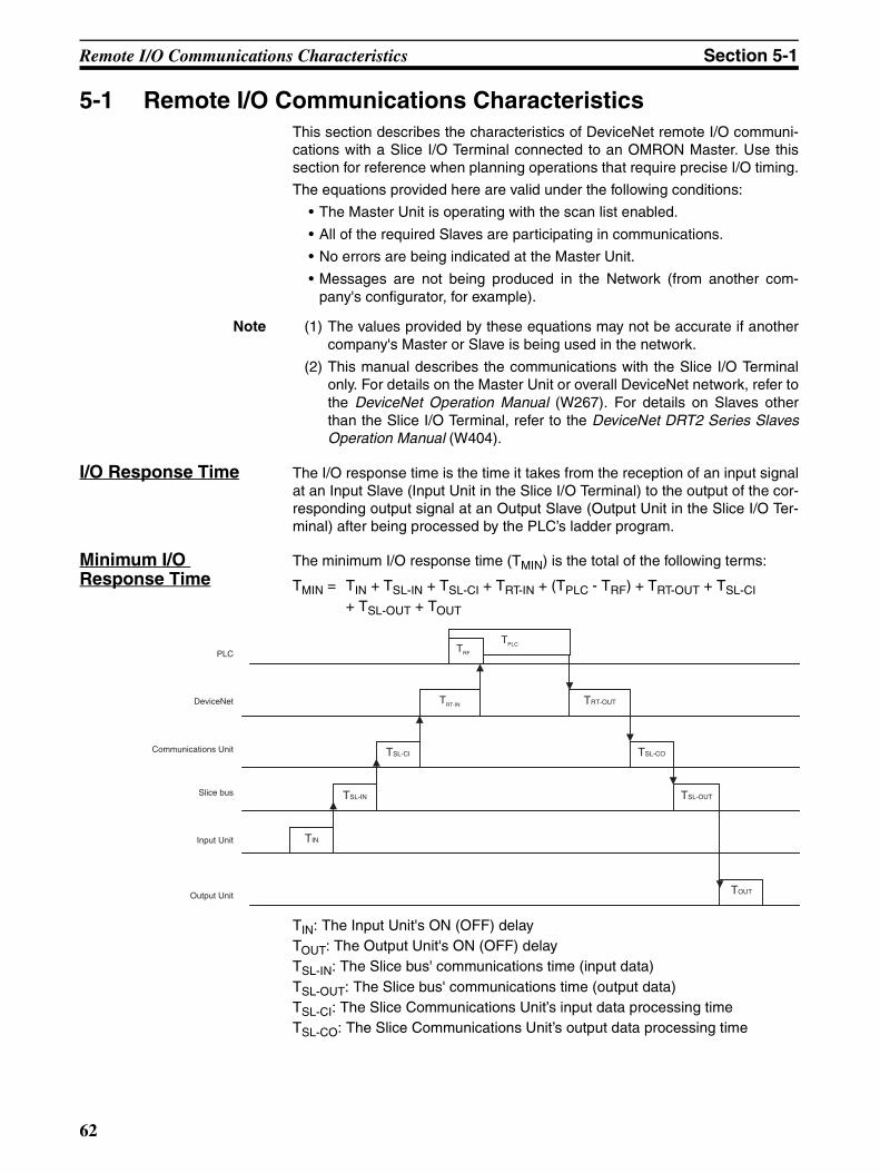
Remote I/O Communications Characteristics Section 5-1
5-1 Remote I/O Communications CharacteristicsThis section describes the characteristics of DeviceNet remote I/O communi-cations with a Slice I/O Terminal connected to an OMRON Master. Use thissection for reference when planning operations that require precise I/O timing.
The equations provided here are valid under the following conditions:
• The Master Unit is operating with the scan list enabled.
• All of the required Slaves are participating in communications.
• No errors are being indicated at the Master Unit.
• Messages are not being produced in the Network (from another com-pany's configurator, for example).
Note (1) The values provided by these equations may not be accurate if anothercompany's Master or Slave is being used in the network.
(2) This manual describes the communications with the Slice I/O Terminalonly. For details on the Master Unit or overall DeviceNet network, refer tothe DeviceNet Operation Manual (W267). For details on Slaves otherthan the Slice I/O Terminal, refer to the DeviceNet DRT2 Series SlavesOperation Manual (W404).
I/O Response Time The I/O response time is the time it takes from the reception of an input signalat an Input Slave (Input Unit in the Slice I/O Terminal) to the output of the cor-responding output signal at an Output Slave (Output Unit in the Slice I/O Ter-minal) after being processed by the PLC’s ladder program.
Minimum I/O Response Time
The minimum I/O response time (TMIN) is the total of the following terms:
TMIN = TIN + TSL-IN + TSL-CI + TRT-IN + (TPLC - TRF) + TRT-OUT + TSL-CI + TSL-OUT + TOUT
TIN: The Input Unit's ON (OFF) delayTOUT: The Output Unit's ON (OFF) delayTSL-IN: The Slice bus' communications time (input data)TSL-OUT: The Slice bus' communications time (output data)TSL-CI: The Slice Communications Unit’s input data processing timeTSL-CO: The Slice Communications Unit’s output data processing time
TPLC TRF
TRT-IN
TSL-CI
TSL-IN
TIN
TRT-OUT
TSL-CO
TSL-OUT
TOUT
PLC
DeviceNet
Communications Unit
Slice bus
Input Unit
Output Unit
62
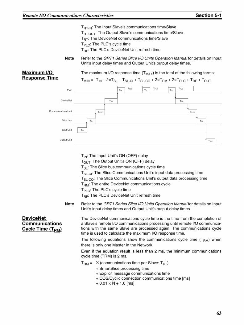
Remote I/O Communications Characteristics Section 5-1
TRT-IN: The Input Slave's communications time/SlaveTRT-OUT: The Output Slave's communications time/SlaveTRT: The DeviceNet communications time/SlaveTPLC: The PLC's cycle timeTRF: The PLC's DeviceNet Unit refresh time
Note Refer to the GRT1 Series Slice I/O Units Operation Manual for details on InputUnit’s input delay times and Output Unit’s output delay times.
Maximum I/O Response Time
The maximum I/O response time (TMAX) is the total of the following terms:
TMIN = TIN + 2×TSL + TSL-CI + TSL-CO + 2×TRM + 2×TPLC + TRF + TOUT
TIN: The Input Unit's ON (OFF) delayTOUT: The Output Unit's ON (OFF) delayTSL: The Slice bus communications cycle timeTSL-CI: The Slice Communications Unit’s input data processing timeTSL-CO: The Slice Communications Unit’s output data processing timeTRM: The entire DeviceNet communications cycleTPLC: The PLC's cycle timeTRF: The PLC's DeviceNet Unit refresh time
Note Refer to the GRT1 Series Slice I/O Units Operation Manual for details on InputUnit’s input delay times and Output Unit’s output delay times
DeviceNet Communications Cycle Time (TRM)
The DeviceNet communications cycle time is the time from the completion ofa Slave's remote I/O communications processing until remote I/O communica-tions with the same Slave are processed again. The communications cycletime is used to calculate the maximum I/O response time.
The following equations show the communications cycle time (TRM) whenthere is only one Master in the Network.
Even if the equation result is less than 2 ms, the minimum communicationscycle time (TRM) is 2 ms.
TRM = Σ (communications time per Slave: TRT)+ SmartSlice processing time+ Explicit message communications time+ COS/Cyclic connection communications time [ms]+ 0.01 × N + 1.0 [ms]
TPLC TRF
TPLC TRF
TPLC TRF
TRM
TSL-CI
TSL
TIN
TRM
TSL-CO
TSL
TOUT
PLC
DeviceNet
Communications Unit
Slice bus
Input Unit
Output Unit
63

Remote I/O Communications Characteristics Section 5-1
• Communications time per Slave:Time required for each Slave. (See the following page.)For a Slice I/O Terminal, this is the communications time for one of theCommunications Unit’s Slaves.The “Σ (communications time per Slave)” is the total of the processingtimes for the Slaves in the Network.
• SmartSlice processing time:This processing time is 3.5 ms, only when there isn’t a single input,output or mixed I/O Slave in the network with more than 8 bytes of I/Odata.
• Explicit message communications time:0.11 × TB + 0.6 [ms]Added as a delay time when explicit message communications (sendor receive) are used.
TB: Constant (500 kbps: TB = 2; 125 kbps: TB = 4; 125 kbps: TB = 8)
• COS/Cyclic connection communications time:(0.05 + 0.008 × S) × TB × n [ms]Added as a delay time when COS/Cyclic connection is used for com-munications.S: Total size (bytes) of the COS/Cyclic connection’s input size and out-put size.n: Number of nodes for which COS/Cyclic connections occur at thesame time during one communications cycle.
• N: Number of Slaves
Communications Time per SlaveTRT-IN and TRT-OUT
The communications time per Slave is the time required for communicationsto be performed with a single Slave.
The following equations show the communications time per Slave (TRT) foreach kind of Slave Unit. For a Slice I/O Terminal, the communications time perSlave is the communications time per Slave with the DeviceNet Communica-tions Unit. In the Slice I/O Terminal, 2 input words (4 bytes) are used for the I/O Unit interface’s status flags, so those 4 bytes must be included in the totalwhen calculating the number of input bytes.
Output Slaves with up to 8 Bytes of Output
TRT = 0.016 × TB × SOUT1 + 0.11 × TB + 0.07 [ms]
SOUT1: The number of Output Slave output words
TB: TB = 2 at 500 kbps; TB = 4 at 250 kbps; TB = 8 at 125 kbps
Input Slaves with up to 8 Bytes of Input
TRT = 0.016 × TB × SIN1 + 0.06 × TB + 0.05 [ms]
SIN1: The number of Input Slave input words
TB: TB = 2 at 500 kbps; TB = 4 at 250 kbps; TB = 8 at 125 kbps
Mixed I/O Slaves with up to 8 Bytes of I/O Words
TRT = 0.016 × TB × (SOUT2 + SIN2) + 0.11 × TB + 0.07 [ms]
SOUT2: The number of Mixed I/O Slave output words
SIN2: The number of Mixed I/O Slave input word
TB: TB = 2 at 500 kbps; TB = 4 at 250 kbps; TB = 8 at 125 kbps
Input, Output, or Mixed I/O Slaves with More than 8 Bytes of I/O Words
TRT = TOH + TBYTE-IN × BIN + TBYTE-OUT × BOUT [ms]
TOH: The overhead protocol
TBYTE-IN: The input byte transmission time
BIN: The number of input bytes
64

Remote I/O Communications Characteristics Section 5-1
TBYTE-OUT: The output byte transmission time
BOUT: The number of output bytes
The number of output bytes (BOUT) is 0 for Input Slaves, and the number ofinput bytes (BIN) is 0 for Output Slaves.
Refresh Time (TRF) The refresh time is the time required to exchange I/O data between the PLC'sCPU Unit and the DeviceNet Master Unit. The PLC's cycle time is increasedwhen a Master Unit is mounted, as shown below.
Note Refer to the PLC's operation manual for more details on the refresh time andthe PLC's cycle time.
Master Units for CS, CJ, C200HX/HG/HE (-Z), and C200HS PLCs
When a Master Unit is mounted to the PLC, the PLC's cycle time (I/O refresh-ing) is increased by the amount shown in the following table.
Note The number of words refreshed is the total number of words in the I/O Areathat are allocated to the Slaves, including any unused words between thosewords actually used by the Slaves. For example, if there are only two InputSlaves with node addresses 1 and 5, the 5 input words for nodes 1 through 5would be refreshed even though the input words for nodes 2, 3, and 4 areunused.If message communications are being performed, just add the number ofwords used in message communications to the above number of words forwhenever messages are being processed.
Slice Bus Communications Cycle Time (TSL)
The Slice bus communications cycle time is the delay in the Slice I/O Terminalfrom the end of communications with one I/O Unit until the start of communi-cations with the next Unit.
TSL = 0.66+ (total number of input bytes of word Input Units) × 0.011+ (total number of input bits of bit Input Units) × 0.009+ (total number of output bytes of word Output Units) × 0.004+ (total number of output bits of bit Output Units) × 0.001 [ms]
Communications Unit Processing Time(TSL-CI and TSL-CO)
The DeviceNet Communications Unit processing time is the time required forsoftware processing in the Communications Unit. The processing time is dif-ferent for input data and output data, as shown below.
TSL-CI = 0.71 + total number of input data bytes × 0.003 [ms]TSL-CO = 0.2 + total number of output data bytes × 0.001 [ms]
Baud rate TOH TBYTE-IN TBYTE-OUT
500 kbps 0.306 ms 0.040 ms 0.036 ms
250 kbps 0.542 ms 0.073 ms 0.069 ms
125 kbps 1.014 ms 0.139 ms 0.135 ms
Process Processing time
I/O refreshing DeviceNet Unit I/O refreshing:• For CS/CJ-series Master Unit:
0.7 + 0.001 × number of words (ms) (See note.)• For C200HX/HG/HE (-Z) PLCs:
1.72 + 0.022 × number of words (ms) (See note.)• For C200HS PLCs:
2.27 + 0.077 × number of words (ms) (See note.)
65
Message Communications Characteristics Section 5-2
Slice Bus Communications Time(TSL-IN and TSL-OUT)
The Slice bus communications time is the time required to communicate withan Input Unit (TSL-IN) or Output Unit (TSL-OUT) in the Slice I/O Terminal.
TSL-IN = 0.01 × number of input data bytes [ms]TSL-OUT = 0.18 + total number of output data bytes × 0.002 [ms]
5-2 Message Communications Characteristics
5-2-1 Message Communications TimeThe message communications time is the time required for a message sent tothe Slice I/O Terminal to travel over the Network and arrive at the Slice I/OTerminal. (The message may be data from a SEND(090)/RECV(098) instruc-tion or a FINS command from a CMND(490)/IOWR(223) instruction.)
Communications Time to the DeviceNet Communications Unit
Use the following equation to calculate the message communications time tothe DeviceNet Communications Unit.
Message communications time = DeviceNet communications cycle time(TRM) × (Number of message bytes + 15) ÷ 6 + 1
The number of message bytes is the number of bytes of data after the FINScommand’s command code. The equation for the DeviceNet communicationscycle time (TRM) is in 5-1 Remote I/O Communications Characteristics.
Communications Time to the Slice I/O Unit
If a Slice I/O Unit is the final message destination, the message communica-tions time over the Slice bus must be added to calculate the total messagecommunications time. Use the following equation to calculate the messagecommunications time over the Slice bus.
Message communications time = TSL × Number of frames
Number of frames = Number of message bytes ÷ 30 (round up fractions)
Note (1) If the CPU Unit attempts to send another message or receives a messagefrom another node before the message communications time has fin-ished, the response message being sent or the message being receivedfrom another node may be destroyed. Always perform message commu-nications at intervals longer than the message communications time anduse message instructions (SEND(090), RECV(098), CMND(490), andIOWR(223)). Never send messages to any one node at intervals lessthan the message communications time.If send or receive messages are destroyed, the error record will be placedin the error history of the Master Unit. If an error occurs, read the errorhistory using the FINS command or monitor the error history from theConfigurator.
(2) The above equations provide find the approximate message communica-tions time, but not the maximum time. The message communicationstime will depend on the frequency of the message communications, theload on the remote node, the communications cycle time, and other fac-tors. For any one Master Unit, the message communications time may begreatly increased due to heavy loads.
66

SECTION 6Troubleshooting
This section describes error processing and troubleshooting procedures needed to keep the DeviceNet Network operatingproperly.
6-1 Troubleshooting Overview . . . . . . . . . . . . . . . . . . . . . . . . . . . . . . . . . . . . . . . 68
6-1-1 Checking the Slice I/O Terminal’s Status . . . . . . . . . . . . . . . . . . . . . 68
6-1-2 LED Indicators . . . . . . . . . . . . . . . . . . . . . . . . . . . . . . . . . . . . . . . . . 68
6-2 LED Indicators and Error Processing . . . . . . . . . . . . . . . . . . . . . . . . . . . . . . . 68
6-3 Reading the Error History with the DeviceNet Configurator . . . . . . . . . . . . . 71
6-3-1 DeviceNet Communications Error History. . . . . . . . . . . . . . . . . . . . 71
6-3-2 Slice I/O Terminal Error History . . . . . . . . . . . . . . . . . . . . . . . . . . . 72
6-4 Other Errors. . . . . . . . . . . . . . . . . . . . . . . . . . . . . . . . . . . . . . . . . . . . . . . . . . . 74
67

Troubleshooting Overview Section 6-1
6-1 Troubleshooting Overview
6-1-1 Checking the Slice I/O Terminal’s StatusThe following two methods can be used to check for Slice I/O Terminal errors.Use the appropriate method for the conditions.
6-1-2 LED IndicatorsThe following LED indicators in the Slice I/O Terminal show the system status.The Slice I/O Terminal is operating normally when all of the LED indicatorsare lit green (including indicators on the DeviceNet Communications Unit,Slice I/O Units, Turnback Units, etc.).
6-2 LED Indicators and Error ProcessingThe following table shows the meaning of the LED indicators on each Unitused in a Slice I/O Terminal, as well as error processing required when anerror is indicated.
Method Programming Device
Features
Using LED indicators Not required. The general error status can be determined without using the DeviceNet Configurator.
Using DeviceNet Configurator
Required. The DeviceNet Configurator can be used to find detailed information about the error from the error contents.
MS LED: Indicates the status of the DeviceNet Communications Unit. NS LED: Indicates the status of DeviceNet communications.TS LED: Indicates the status of the entire Slice I/O Terminal.UNIT PWR: Indicates the status of the Unit power supply.I/O PWR: Indicates the status of the I/O power supply.
TS LEDs: Indicate the status of each Slice I/O Unit.
Unit LED name
Color Status Meaning Likely cause of error
DeviceNet Communica-tions Unit
MS Green Unit operating normally. ---
--- Power is not being supplied to the Unit.
Check whether power is being supplied by the Unit power supply.
Red Unit hardware failure Turn the power OFF and then ON again. Replace the Unit if the error recurs.
Red Parameter data is invalid. Use a Programming Device to write the cor-rect data again.
Backup data is invalid. Backup the data again.
Registration table data is invalid.
Register the I/O configuration table again.
MS
MS
MS
MS
68

LED Indicators and Error Processing Section 6-2
DeviceNet Communica-tions Unit, continued
NS Green DeviceNet communications are normal.
---
--- Waiting for completion of node address duplication check.
If the problem occurs only in a particular Slave, check the baud rate and restart the Slave.
Red There is a node address duplication error at another Unit in the DeviceNet network.
Set the node addresses again to eliminate the duplication, and restart the Slice I/O Ter-minal.
DeviceNet communications stopped because of too many data errors.
Check the following items and restart the Slice I/O Terminal.• Is the baud rate the same as the Master’s?• Are lengths of cables (trunk and branch
lines) correct?• Are cables short-circuited, broken, or
loose?• Is terminating resistance connected to
both ends of the trunk line only?• Is noise interference excessive?
Red DeviceNet communications timeout occurred.
Check the following items.
• Is the baud rate the same as the Master’s?• Are lengths of cables (trunk and branch
lines) correct?• Are cables short-circuited, broken, or
loose?• Is terminating resistance connected to
both ends of the trunk line only?• Is noise interference excessive?
Green Online with DeviceNet, but waiting for a connection with the Master.
Check whether the Master has started properly.Check whether the Slice I/O Terminal is reg-istered in the Master’s scan list.
Unit LED name
Color Status Meaning Likely cause of error
NS
NS
NS
NS
NS
69

LED Indicators and Error Processing Section 6-2
DeviceNet Communica-tions Unit, continued
TS Green The Slice bus is operating normally.
---
--- Power is not being supplied to the Unit.
Check whether power is being supplied by the Unit power supply.
Red Slice I/O Unit configuration error occurred.
Check the following items.• Are more than 64 I/O Units connected?• Are more than 128 bytes of I/O data being
used?• Has the I/O configuration changed since
the I/O configuration table was registered?
Red
(for 2 s)
Backup operation failed. Backup the data again.
Restore operation failed. Reinstall the Unit in which the data was being restored and turn the power ON again.
Red Slice bus communications error occurred.
Check whether the Slice I/O Terminal’s base block is connected properly.
When the registration table function is enabled, the actual configuration does not match the registered configuration.
Correct the configuration and turn the power ON again.
Green The total number of I/O points in the Slice I/O Terminals exceeds the maximum.
Correct the Unit configuration and number of I/O points and turn the power ON again.
Restore operation in progress Wait until the restore operation is com-pleted.
Backup operation in progress Wait until the backup operation is com-pleted.
Joining nodes to network Wait until the nodes have been added to the network.
UNIT PWR
Green Unit power supply is providing power normally.
---
--- Unit power supply is not being supplied to the Unit.
Check whether power is being supplied by the Unit power supply.
IOPWR
Green I/O power supply is providing power normally.
---
--- I/O power supply is not being supplied to the Unit.
Check whether power is being supplied by the I/O power supply.
Slice I/O Units TS Green Slice I/O Unit operating nor-mally.
---
--- Unit power supply is not being supplied to the Unit.
Check whether power is being supplied by the Unit power supply.
Red Unit hardware failure Turn the power OFF and then ON again. Replace the Unit if the error recurs.
Communications error occurred.
Check whether the connector is inserted properly.
Green Restore operation in progress Wait until the restore operation is com-pleted.
Backup operation in progress Wait until the backup operation is com-pleted.
GRT1-PD2 I/O Power Supply Unit
IOPWR
Green I/O power supply is providing power normally.
---
--- I/O power supply is not being supplied to the Unit.
Check whether power is being supplied by the I/O power supply.
Unit LED name
Color Status Meaning Likely cause of error
TS
TS
TS
TS
NS
NS
TS
TS
TS
TS
TS
70
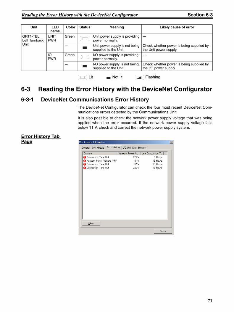
Reading the Error History with the DeviceNet Configurator Section 6-3
Lit Not lit Flashing
6-3 Reading the Error History with the DeviceNet Configurator
6-3-1 DeviceNet Communications Error HistoryThe DeviceNet Configurator can check the four most recent DeviceNet Com-munications errors detected by the Communications Unit.
It is also possible to check the network power supply voltage that was beingapplied when the error occurred. If the network power supply voltage fallsbelow 11 V, check and correct the network power supply system.
Error History Tab Page
GRT1-TBL Left Turnback Unit
UNIT PWR
Green Unit power supply is providing power normally.
---
--- Unit power supply is not being supplied to the Unit.
Check whether power is being supplied by the Unit power supply.
IOPWR
Green I/O power supply is providing power normally.
---
--- I/O power supply is not being supplied to the Unit.
Check whether power is being supplied by the I/O power supply.
Unit LED name
Color Status Meaning Likely cause of error
71

Reading the Error History with the DeviceNet Configurator Section 6-3
The following table shows the details of each indicated error.
6-3-2 Slice I/O Terminal Error HistoryThe DeviceNet Configurator can read the error history details of the mostrecent errors that occurred in the Slice I/O Terminal.
Error History Tab Page
Error name Contents Error processing Saved in error history when
power goes OFF?
Connection Time Out
DeviceNet communications timeout
Generally, the error is caused by noise and commu-nications are restored automatically. If the problem occurs frequently, check the following items.
• Is the baud rate the same as the Master’s?• Are lengths of cables (trunk and branch lines) cor-
rect?• Are cables short-circuited, broken, or loose?• Is terminating resistance connected to both ends
of the trunk line only?• Is noise interference excessive?
Yes
Bus Off error detected
DeviceNet communications bus off
(Communications stopped because of too many data errors.)
Check the following items and restart the Slice I/O Terminal.
• Is the baud rate the same as the Master’s?• Are lengths of cables (trunk and branch lines) cor-
rect?• Are cables short-circuited, broken, or loose?• Is terminating resistance connected to both ends
of the trunk line only?• Is noise interference excessive?
Yes
Node address duplication
There is a node address duplication error at another Unit in the DeviceNet network.
Set the node addresses again to eliminate the dupli-cation, and restart the Slice I/O Terminal.
Yes
72

Reading the Error History with the DeviceNet Configurator Section 6-3
Communications Unit Error History
Slice Bus Error History
Error code (Hex)
Contents Details Saved in error history when
power goes OFF?
Corrective action
1st byte 2nd byte
0002 WDT error 0x00 0x00 Yes Replace the Unit if the error occurs frequently.
0370 Verification error (Slave miss-ing)
00 00 No Connect the missing Unit and restart.
0372 Verification error (unregistered Slave joined network)
0x80: Slice I/O
Node address (Hex)
No Remove the unregistered Unit and restart.
021A Setting table logic error
Cause:There was a checksum error in on of the following tables or a set value was out-of-range.• Network parameters• Registration table• Slave parameters• Backup restore data
0x00 0x0A: Registra-tion table0x0B: Slave parameters
0x0C: Network parameters0x0F: Backup restore data
Yes Download the settings again.
0602 Memory access error
Cause:• A hardware error occurred in
the Unit’s internal non-vola-tile memory.
• E2P hardware error• Backup communications fail-
ure• FROM save failure• EEPROM save failure• FROM hardware error• ADR failure (communications
failure)
0x01: Read error0x02: Write error
0x07: Error his-tory0x09: Identity information
0x0A: Registra-tion table0x0C: Network parameters0x0F: Backup restore data (E2P/FROM)
Yes (No for error history only)
Replace the Unit if the error occurs frequently.
Error code (Hex)
Contents Details Saved in error history when
power goes OFF?
Corrective action
1st byte 2nd byte
0300 Backup data reception error 0x80: Slice I/O
Node address (Hex)
No Verify that the Unit is con-nected properly. Check whether there is excessive noise in the surroundings.
0374 Transmission error
Cause:A transmission error occurred.
0x80: Slice I/O
Node address (Hex)
No Verify that the Unit is con-nected properly. Check whether there is excessive noise in the surroundings.
0375 Communications stopped due to a transmission error.Cause:The Unit is set to stop commu-nications for communications errors and a transmission error occurred. (Error code 0374 will not occur in this case.)
0x80: Slice I/O
Node address (Hex)
Yes Verify that the Unit is con-nected properly. Check whether there is excessive noise in the surroundings.
73

Other Errors Section 6-4
6-4 Other Errors
0376 Slave duplication errorCause:A Slave duplication error occurred.
0x80: Slice I/O
Node address (Hex)
No Verify that the Unit is con-nected properly and turn the power ON again.
0378 I/O size error 0x00 0x00 No Verify that the Unit is con-nected properly and turn the power ON again.
0379 Slice configuration error 0x00 0x00 No Verify that the Unit is con-nected properly and turn the power ON again.
Status Likely cause and remedy
The Communications Unit’s Unit Power indicator is flash-ing.
The Unit power supply capacity is insufficient. Check the entire Slice I/O Terminal’s power supply requirement and replace the power supply with one that has sufficient capacity.
The Communications Unit repeatedly checks indicators (MS/NS indicator flashing green and red).The I/O Unit repeatedly checks indicators (TS indica-tor flashing green and red).
The Unit power supply capacity is insufficient. Check the entire Slice I/O Terminal’s power supply requirement and replace the power supply with one that has sufficient capacity.
The Communications Unit’s TS indicator flashes green. The I/O Unit’s indicator in front of the bad connection lights green and the indicator behind the bad connection goes OFF.
The slide connector on the left side of the affected Unit is not connected properly. Connect this slide connector properly and turn the power ON again.
The Communications Unit’s TS indicator flashes green and the I/O Unit’s TS indicator flashes green.
The End Unit is not connected properly. Connect the End Unit properly and turn the power ON again.
After the Communications Unit’s MS indicator lights green, NS indicator lights red immediately, without flashing.
Check the following items and restart the problem Slave.• A node address is duplicated.
Check all of the node addresses and set them again to eliminate the duplication.• Check whether the baud rates match on the Master and all Slaves.
If there are any Slaves with different baud rates, set them to the same baud rate.• See the troubleshooting steps below under the error heading “The NS indicator lights
green but changes to red after a short time.”• If a particular Slave's NS indicator is always red, replace that Slave.
Error code (Hex)
Contents Details Saved in error history when
power goes OFF?
Corrective action
1st byte 2nd byte
CommunicationsUnit Indicator
I/O Unit Indicator
Bad connection
Not lit (OFF)
LED Indicator
CommunicationsUnit Indicator
I/O Unit Indicator
Bad connection
End UnitLED Indicators
74

Other Errors Section 6-4
The NS indicator lights green but changes to red after a short time.ORThe NS indicator lights green but flashes red after a short time.
Check the following points and then restart the faulty Slave.• Verify that there are 121-Ω Terminating Resistors connected at both ends of the trunk
line. Connect 121-Ω Terminating Resistors if the resistance is not correct.• Check whether the baud rates match on the Master and all Slaves.
If there are any Slaves with different baud rates, set them to the same baud rate.• Check whether all of the Slaves' settings are correct.• Check whether the communications cables are connected properly.• Check whether the power supply is set correctly and the power supply cables are con-
nected properly.• Check all the nodes for broken wires in the communications and power supply cables
attached to the connectors.• Check whether communications power is correctly supplied to the network.• If there is nearby equipment that generates electrical noise, take steps to shield the Mas-
ter, Slaves, and communications cables from the noise.• If an error has occurred in a network with an OMRON Master Unit, refer to the DeviceNet
master operation manual.If an error has occurred in a network with a another company's Master Unit, refer to the relevant operation manual.
• If a particular Slave's NS indicator is always red, replace that Slave.
The NS indicator remains OFF.
• Check whether the baud rates match on the Master and all Slaves.If there are any Slaves with different baud rates, set them to the same baud rate.
• Check that the Slave's connector is connected correctly.• Check that the 24 VDC communications power supply is being supplied properly.• Check that the Master is operating properly.
When using an OMRON Master Unit, refer to the DeviceNet master operation manual.If another company's Master is being used, refer to the relevant operation manual.
• Check whether the communications cables are connected properly.• Check whether the power supply is set correctly and the power supply cables are con-
nected properly.• Check for broken wires in the communications and power supply cables attached to the
connectors.
The NS indicator continuously flashes green.
• Check that the Master is operating properly.When using an OMRON master, refer to the DeviceNet master operation manual.If another company's Master is being used, refer to the relevant operation manual.
• Check whether the Slave is registered in the Master's scan list.If an OMRON Master Unit is being used, a new Slave cannot be added to the network if the Master is operating with the scan list enabled. First clear the scan list, check that all the Slaves have joined the network, and then create the scan list.If another company's Master is being used, refer to the relevant operation manual for details on registering a new Slave in its scan list.
Status Likely cause and remedy
75

Other Errors Section 6-4
The NS indicator alternates between being a constant green and flashing green.ORThe NS indicator alternates between flashing red and flashing green.
When using an OMRON Master Unit, check the following points and perform the error processing steps according to the indicator status.
• Register the scan list again.First clear the scan list, check that all the Slaves have joined the network, and then cre-ate the scan list.
• Check that the Slave's allocated I/O Area does not overlap with that of another Slave. If there is an overlap, change the Slave's node address to eliminate the overlap.
• Check that the allocated I/O Area does not exceed the allowable range shown below. If the I/O Area exceeds this range, change the Slave's node address to correct the prob-lem.
When using another company's Master Unit, check that the I/O size registered in the Mas-ter's scan list matches the actual I/O size of the Slave.The I/O size is recorded in the following attributes of the Connection Object:
Interface 2 (Polled I/O Connection)Produced Connection Size (input size)Consumed Connection Size (output size)
OR:Interface 3 (Bit-strobed I/O Connection)Produced Connection Size (input size)
Refer to Appendix A DeviceNet Explicit Messages, and register the correct values in the Master Unit's scan list. Refer to the DeviceNet master operation manual for details on reg-istering values.
Status Likely cause and remedy
76

Appendix ADeviceNet Explicit Messages
DeviceNet explicit messages sent from the Master Unit to a GRT1 Series DeviceNet Communications Unit canbe used to read or write any parameter of a specified GRT1 Series DeviceNet Communications Unit.
The DeviceNet Communications Units process the commands sent from the Master and then returnresponses.
Basic Format of Explicit MessagesThe basic format of each command and response is shown below.
Command Block
Destination Node AddressThe node address of the Unit that is sending the explicit messages (commands) is specified as a single-bytehexadecimal.
Service Code, Class ID, Instance ID, Attribute IDThe parameters used for specifying the command, processing object, and processing content.
Note The number of bytes designated for Class ID, Instance ID, and Attribute ID depend on the Master Unit.When sent from an OMRON DeviceNet Master, the Class ID and Instance ID are 2 bytes (4 digits), andAttribute ID is 1 byte (2 digits).
DataData is not required when the read command is used.
Response Block
Normal Response Block
Error Response Block
Number of Bytes ReceivedThe number of bytes received from the source node address is returned in hexadecimal. When an errorresponse is returned for an explicit message, the number of bytes is always 0004 Hex.
Source Node AddressThe node address of the node from which the command was sent is returned in hexadecimal.
Destination node address
Servicecode
ClassID
InstanceID
Attribute ID
Data
Number of bytes received
Source node address
Service code Data
Number of bytes received:
0004 Hex (fixed)
Source node address
Service code Error code
77

DeviceNet Explicit Messages Appendix A
Service CodeFor normal completion, the value when the leftmost bit of the service code specified in the command turns ONis stored as shown in the following table.
When an error response is returned for an explicit message, the value is always 94 Hex.
DataRead data is included only when a read command is executed.
Error CodesThe explicit message error code. For details, refer to the list of error codes in the following table.
List of Error Codes
Explicit Messages Common to All Slaves
Reading General Status
Note Refer to 2-2-3 I/O Allocation to the Slice I/O Terminal’s Master Unit for information on the Generic StatusFlags
Function Command service code Response service code
Write data 10 Hex 90 Hex
Read data 0E Hex 8E Hex
Reset 05 Hex 85 Hex
Save 16 Hex 96 Hex
Response code Error name Cause
08FF Service not supported The Service code is incorrect.
09FF Invalid Attribute value The specified Attribute value is not supported.
The data written was outside valid range.
16FF Object does not exist The specified Instance ID is not supported.
15FF Too much data The data is larger than the specified size.
13FF Not enough data The data is smaller than the specified size.
0CFF Object state conflict The specified command cannot be executed due to an internal error.
20FF Invalid parameter The specified operation command data is not supported.
0EFF Attribute not settable An Attribute ID supported only for reading has been executed for a write service code.
10FF Device state conflict The specified command cannot be executed due to an internal error.
14FF Attribute not supported The specified Attribute is not supported.
19FF Store operation failure The data cannot be stored in memory.
2AFF Group 2 only server general failure
The specified command or Attribute is not supported or the Attribute was not set.
Explicit message
Read/write Function Command Response
Service code
Class ID Instance ID
Attribute ID
Data size
General Status Read
Read Reads the speci-fied Communica-tions Unit's status flags (8 bits).
0E Hex 95 Hex 01 Hex 65 Hex --- 1 byte
78

DeviceNet Explicit Messages Appendix A
Setting and Monitoring the Unit Conduction Time
Alarm Information Read
Note The following tables show the alarm data details.
The 4 bits allocated to each Slice I/O Node have the following functions:
Note The Warning/Alarm details depend on the Communications Unit. Refer to the Unit’s operation manual.
Explicit message
Read/write
Function Command Response
Service code
Class ID
Instance ID
Attribute ID
Data size
Unit Main-tenance Set Value
Read Reads the set value for the Communica-tions Unit's Unit Conduction Time (Power ON time, unit: 0.1 hr)
0E Hex 95 Hex 01 Hex 73 Hex --- 4 bytes00000000 to FFFFFFFF Hex
(0 to 4294967295)
Write Writes the set value for the Communica-tions Unit's Unit Conduction Time (Power ON time, unit: 0.1 hr)
10 Hex 95 Hex 01 Hex 73 Hex 4 bytes00000000 to FFFFFFFF Hex(0 to 4294967295)
---
Unit Main-tenance Present Value
Read Reads the present value for the Com-munications Unit's Unit Conduction Time (Power ON time, unit: 0.1 hr)
0E Hex 95 Hex 01 Hex 71 Hex --- 4 bytes00000000 to FFFFFFFF Hex(0 to 4294967295)
Unit Main-tenance Flag
Read Reads the monitor status of the Com-munications Unit's Unit Conduction Time (Power ON time)
0E Hex 95 Hex 01 Hex 72 Hex --- 1 byte00: Within range
01: Out of range (over the monitor value)
Explicit message
Read/write Function Command Response
Service code
Class ID Instance ID Attribute ID
Data size
Alarm Infor-mation Read
Read Reads the Slice I/O Terminal’s alarm data.
0E Hex 9C Hex 01 Hex 73 Hex --- 32 bytes (See note.)
Word offset
Bit
15 12 11 8 7 4 3 0
+0 Slice I/O Node #4 Slice I/O Node #3 Slice I/O Node #2 Slice I/O Node #1
+1 Slice I/O Node #8 Slice I/O Node #7 Slice I/O Node #6 Slice I/O Node #5
+2 Slice I/O Node #12 Slice I/O Node #11 Slice I/O Node #10 Slice I/O Node #9
:
+13 Slice I/O Node #56 Slice I/O Node #55 Slice I/O Node #54 Slice I/O Node #53
+14 Slice I/O Node #60 Slice I/O Node #59 Slice I/O Node #58 Slice I/O Node #57
+15 Slice I/O Node #64 Slice I/O Node #63 Slice I/O Node #62 Slice I/O Node #61
Bit 0 Warning (Minor error)
Bit 1 Alarm (Major error)
Bit 2 Reserved
Bit 3 Reserved
79

DeviceNet Explicit Messages Appendix A
Using Explicit MessagesThe following example shows how to use explicit messages with a DeviceNet Communications Unit connectedto a CS1W-DRM21 DeviceNet Master Unit.
Example: Sending a “Unit Maintenance Present Value Read” command to the DeviceNet CommunicationsUnit.
Example: DeviceNet Master Unit’s node address: 05
Unit number: 0
Unit address: FE Hex (or 10 Hex)
DeviceNet Communication Unit’s node address: 11
OperationReads the Unit maintenance PV of the Slice I/O Terminal’s DeviceNet Communications Unit.
The data is read using the EXPLICIT MESSAGE SEND command (2801).
The command data is written in words starting from D01000 in the PLC and the response data is stored inwords starting from D02000.
If the command does not end normally, the end code is stored in D00006 and the send command is re-exe-cuted.
CMND
C
S
D
DeviceNet Master Unit
Ladder program
Explicit message sent
DeviceNet Network
Unit maintenancepresent value
Slice I/O Terminal
80
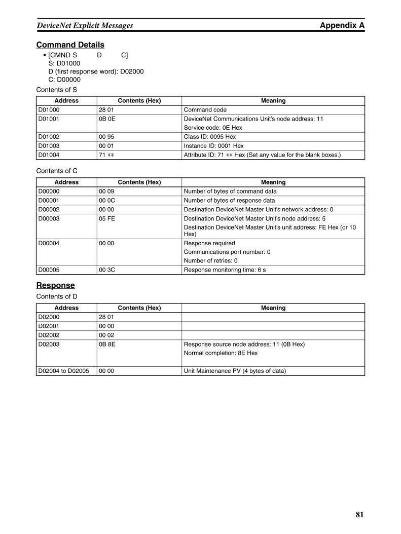
DeviceNet Explicit Messages Appendix A
Command Details• [CMND S D C]
S: D01000 D (first response word): D02000 C: D00000
Contents of S
Contents of C
ResponseContents of D
Address Contents (Hex) Meaning
D01000 28 01 Command code
D01001 0B 0E DeviceNet Communications Unit’s node address: 11
Service code: 0E Hex
D01002 00 95 Class ID: 0095 Hex
D01003 00 01 Instance ID: 0001 Hex
D01004 71 ** Attribute ID: 71 ** Hex (Set any value for the blank boxes.)
Address Contents (Hex) Meaning
D00000 00 09 Number of bytes of command data
D00001 00 0C Number of bytes of response data
D00002 00 00 Destination DeviceNet Master Unit’s network address: 0
D00003 05 FE Destination DeviceNet Master Unit’s node address: 5Destination DeviceNet Master Unit’s unit address: FE Hex (or 10 Hex)
D00004 00 00 Response requiredCommunications port number: 0Number of retries: 0
D00005 00 3C Response monitoring time: 6 s
Address Contents (Hex) Meaning
D02000 28 01
D02001 00 00
D02002 00 02
D02003 0B 8E Response source node address: 11 (0B Hex)Normal completion: 8E Hex
D02004 to D02005 00 00 Unit Maintenance PV (4 bytes of data)
81

DeviceNet Explicit Messages Appendix A
82

Appendix BUsing Another Company's Master Unit
This appendix explains how to operate an OMRON Slave when the Slave is connected to a Master manufac-tured by another company.
Note If the Slave has outputs, do not communicate with the Master through a bit strobe connection. There are several DeviceNet I/O communications methods, including poll and bit strobe connections, butDeviceNet specifications allow the bit strobe connection with inputs only. OMRON Master Units conform to these specifications and communicate with Output Slaves through apoll connection, but some other company's Masters allow bit strobe connections with Output Slaves.Before connecting an OMRON Slave to another company's Master, verify the Master's connection spec-ifications.
When connecting an OMRON Communications Unit to another company's Master, it may be necessary toinstall the OMRON Communications Unit's EDS file in the other company's configurator to set the Communica-tions Unit's information in the Master. With some companies' Masters, the Communications Units can be con-nected without making settings.
With some other companies' configurators and depending on the Communications Unit being used, installingthe OMRON Communications Unit's EDS file in the configurator will allow you to make various parameter set-tings from the configurator.
Note If you cannot obtain a copy of the EDS file or the other company's configurator does not support EDSfiles, settings such as the connection type and data size must be input directly.
Installing EDS Files EDS files are provided by the manufacturer for each Communications Unit and contain settings such as theCommunications Unit's ID and I/O data sizes. If the EDS file is installed in the configurator, the Communica-tions Unit's settings can be changed and the I/O size will be input automatically when the Master's scan list iscreated.
EDS files for the Communications Units described in this manual can be downloaded from the product catalogat the following website:
→http://www.odva.astem.or.jp/
Locate the EDS file for the desired Communications Unit and install that EDS file in the configurator. Refer tothe Configurator’s operation manual for details on the installation procedure.
More Detailed DeviceNet Specifications for Communications UnitsThe following device profiles contain more detailed DeviceNet specifications for Communications Units if moreinformation needs to be registered in the scan list.
83
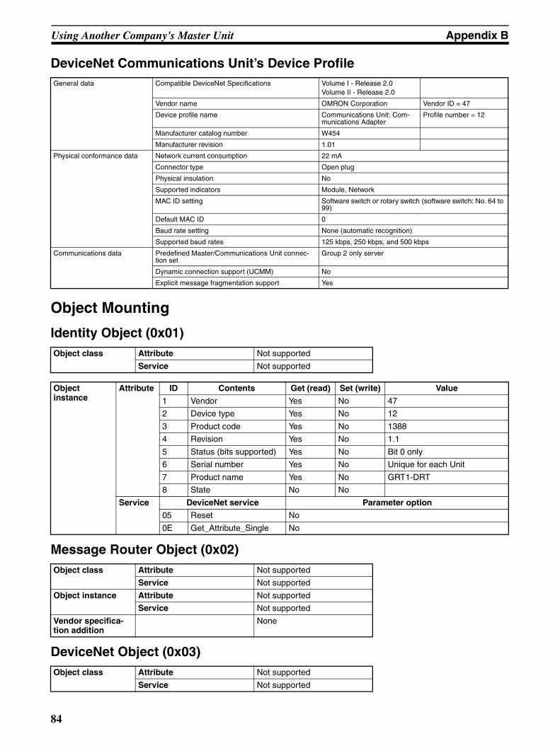
Using Another Company's Master Unit Appendix B
DeviceNet Communications Unit’s Device Profile
Object Mounting
Identity Object (0x01)
Message Router Object (0x02)
DeviceNet Object (0x03)
General data Compatible DeviceNet Specifications Volume I - Release 2.0Volume II - Release 2.0
Vendor name OMRON Corporation Vendor ID = 47
Device profile name Communications Unit: Com-munications Adapter
Profile number = 12
Manufacturer catalog number W454
Manufacturer revision 1.01
Physical conformance data Network current consumption 22 mA
Connector type Open plug
Physical insulation No
Supported indicators Module, Network
MAC ID setting Software switch or rotary switch (software switch: No. 64 to 99)
Default MAC ID 0
Baud rate setting None (automatic recognition)
Supported baud rates 125 kbps, 250 kbps, and 500 kbps
Communications data Predefined Master/Communications Unit connec-tion set
Group 2 only server
Dynamic connection support (UCMM) No
Explicit message fragmentation support Yes
Object class Attribute Not supported
Service Not supported
Object instance
Attribute ID Contents Get (read) Set (write) Value
1 Vendor Yes No 47
2 Device type Yes No 12
3 Product code Yes No 1388
4 Revision Yes No 1.1
5 Status (bits supported) Yes No Bit 0 only
6 Serial number Yes No Unique for each Unit
7 Product name Yes No GRT1-DRT
8 State No No
Service DeviceNet service Parameter option
05 Reset No
0E Get_Attribute_Single No
Object class Attribute Not supported
Service Not supported
Object instance Attribute Not supported
Service Not supported
Vendor specifica-tion addition
None
Object class Attribute Not supported
Service Not supported
84

Using Another Company's Master Unit Appendix B
Note SET condition for MAC ID: MAC ID No. 64 to 99.
Assembly Object (0x04)
Object instance
Attribute ID Contents Get (read) Set (write) Value
1 MAC ID Yes Yes
2 Baud rate Yes No
3 BOI Yes No 00 (hexadecimal)
4 Bus Off counter Yes No
5 Allocation information Yes No
6 MAC ID switch changed No No
7 Baud rate switch changed
No No
8 MAC ID switch value No No
9 Baud rate switch value No No
Service DeviceNet service Parameter option
0E Get_Attribute_Single None
4B Allocate_Master/Slave_Connection_Set
None
4C Release_Master/Slave_Connection_Set
None
Object class Attribute Not supported
Service Not supported
Object instance Attribute ID Contents Get (read) Set (write) Value
1 Number of members in list
No No
2 Member list No No
3 Data Yes No
Service DeviceNet service Parameter option
0E Get_Attribute_Single None
85

Using Another Company's Master Unit Appendix B
The following table shows the assembly instance.
Communications Unit (Input)
General-purpose Communications Unit (Output)
Connection Object (0x05)
Instance number Bit allocation Remarks
Instance 144
Input data
Slice I/O Input data (variable size) Input data
Instance 145
Generic Status
D7 D6 D5 D4 D3 D2 D1 D0 Status data
D15 D14 D13 D12 D11 D10 D9 D8
Instance 146
Registered flags + Abnormal flags
R8 R7 R6 R5 R4 R3 R2 R1 Registered flags (R) + Abnormal flags (A)Numbers in the table correspond to node addresses.
R16 R15 R14 R13 R12 R11 R10 R9
R24 R23 R22 R21 R20 R19 R18 R17
R32 R31 R30 R29 R28 R27 R26 R25
R40 R39 R38 R37 R36 R35 R34 R33
R48 R47 R46 R45 R44 R43 R42 R41
R56 R55 R54 R53 R52 R51 R50 R49
R64 R63 R62 R61 R60 R59 R58 R57
A8 A7 A6 A5 A4 A3 A2 A1
A16 A15 A14 A13 A12 A11 A10 A9
A24 A23 A22 A21 A20 A19 A18 A17
A32 A31 A30 A29 A28 A27 A26 A25
A40 A39 A38 A37 A36 A35 A34 A33
A48 A47 A46 A45 A44 A43 A42 A41
A56 A55 A54 A53 A52 A51 A50 A49
A64 A63 A62 A61 A60 A59 A58 A57
Instance 147
Generic Status + Input data
D7 D6 D5 D4 D3 D2 D1 D0 Status data + Input dataD15 D14 D13 D12 D11 D10 D9 D8
Slice I/O Input data (variable size)
Instance number Bit allocation Remarks
Instance 160Output data
Slice I/O Output data (variable size) Output data
Object class Attribute Not supported
Service Not supported
Maximum number of active connections
1
86

Using Another Company's Master Unit Appendix B
Object instance 1
Section Information Maximum number of instances
Instance type Explicit Message 1
Production trig-ger
Cyclic
Transport type Server
Transport class 3
Attribute ID Contents Get (read) Set (write) Value
1 State Yes No
2 Instance type Yes No 00 (hexadecimal)
3 Transport class trigger
Yes No 83 (hexadecimal)
4 Produced con-nection ID
Yes No ---
5 Consumed con-nection ID
Yes No ---
6 Initial comm. characteristics
Yes No 21 (hexadecimal)
7 Produced con-nection size
Yes No 0026 (hexadeci-mal)
8 Consumed con-nection size
Yes No 0026 (hexadeci-mal)
9 Expected packet rate
Yes Yes
12 Watchdog time-out action
Yes No 01 (hexadecimal)
13 Produced con-nection path length
Yes No 0000 (hexadeci-mal)
14 Produced con-nection path
Yes No
15 Consumed con-nection path length
Yes No 0000 (hexadeci-mal)
16 Consumed con-nection path
Yes No
17 Production inhibit time
Yes No 0000 (hexadeci-mal)
Service DeviceNet service Parameter option
05 Reset None
0E Get_Attribute_Single
None
10 Set_Attribute_Single
None
87

Using Another Company's Master Unit Appendix B
Note See the following table.
Object instance 2
Section Information Maximum number of instances
Instance type Explicit Message 1
Production trig-ger
Cyclic
Transport type Server
Transport class 2
Attribute ID Contents Get (read) Set (write) Value
1 State Yes No
2 Instance type Yes No 01 (hexadecimal)
3 Transport class trigger
Yes No 82 (hexadecimal)
4 Produced con-nection ID
Yes No ---
5 Consumed con-nection ID
Yes No ---
6 Initial comm. characteristics
Yes No 01 (hexadecimal)
7 Produced con-nection size
Yes No See note.
8 Consumed con-nection size
Yes No See note.
9 Expected packet rate
Yes Yes
12 Watchdog time-out action
Yes No 00 (hexadecimal)
13 Produced con-nection path length
Yes No See note.
14 Produced con-nection path
Yes No See note.
15 Consumed con-nection path length
Yes No See note.
16 Consumed con-nection path
Yes No See note.
17 Production inhibit time
Yes No 0000 (hexadeci-mal)
Service DeviceNet service Parameter option
05 Reset None
0E Get_Attribute_Single
None
10 Set_Attribute_Single
None
Model Name Produced connection
size
Produced connection path length
Produced connection path
Consumed connection path length
Consumed connection
path
GRT1-DRT Input Data Variable 0006 20_04_24_05_30_03 0000 ---
Generic Status 0002 0006 20_04_24_64_30_03 0000 ---
Registered Flag + Abnormal Flag
0016 0006 20_04_24_64_30_03 0000 ---
Generic Status + Input Data
Variable 0006 20_04_24_66_30_03 0000 ---
Output Data Variable 0000 20_04_24_66_30_03 0000 ---
88

Using Another Company's Master Unit Appendix B
Note See the following table.
Object instance 3
Section Information Maximum number of instances
Instance type Bit Strobed I/O 1
Production trig-ger
Cyclic
Transport type Server
Transport class 2
Attribute ID Contents Get (read) Set (write) Value
1 State Yes No
2 Instance type Yes No 01 (hexadecimal)
3 Transport class trigger
Yes No 82 (hexadecimal)
4 Produced con-nection ID
Yes No ---
5 Consumed con-nection ID
Yes No ---
6 Initial comm. characteristics
Yes No 02 (hexadecimal)
7 Produced con-nection size
Yes No See note.
8 Consumed con-nection size
Yes No 0800 (hexadeci-mal)
9 Expected packet rate
Yes Yes
12 Watchdog time-out action
Yes No 00 (hexadecimal)
13 Produced con-nection path length
Yes No See note.
14 Produced con-nection path
Yes No See note.
15 Consumed con-nection path length
Yes No 0000
16 Consumed con-nection path
Yes No See note.
Service DeviceNet service Parameter option
05 Reset None
0E Get_Attribute_Single
None
10 Set_Attribute_Single
None
Model Name Produced connection
size
Produced connection path length
Produced connection path
Consumed connection path length
Consumed connection
path
GRT1-DRT Input Data Variable 0006 20_04_24_05_30_03 0000 ---
Generic Status 0002 0006 20_04_24_64_30_03 0000 ---
Generic Status + Input Data
Variable 0006 20_04_24_66_30_03 0000 ---
89

Using Another Company's Master Unit Appendix B
Note See the following table.
Object instance 4
Section Information Maximum number of instances
Instance type COS Cyclic 1
Production trig-ger
Cyclic
Transport type Server
Transport class 2
Attribute ID Contents Get (read) Set (write) Value
1 State Yes No
2 Instance type Yes No 01 (hexadecimal)
3 Transport class trigger
Yes No 12
4 Produced con-nection ID
Yes No ---
5 Consumed con-nection ID
Yes No ---
6 Initial comm. characteristics
Yes No 01 (hexadecimal)
7 Produced con-nection size
Yes No See note.
8 Consumed con-nection size
Yes No 00 (hexadecimal)
9 Expected packet rate
Yes Yes 00
12 Watchdog time-out action
Yes No 00
13 Produced con-nection path length
Yes No See note.
14 Produced con-nection path
Yes No See note.
15 Consumed con-nection path length
Yes No 0004 (hexadeci-mal)
16 Consumed con-nection path
Yes No 202B2401
17 Production inhibit time
Yes No 0000 (hexadeci-mal)
Service DeviceNet service Parameter option
05 Reset None
0E Get_Attribute_Single
None
10 Set_Attribute_Single
None
Model Name Produced connection
size
Produced connection path length
Produced connection path
Consumed connection path length
Consumed connection
path
GRT1-DRT Input Data Variable 0006 20_04_24_05_30_03 0000 ---
Generic Status 0002 0006 20_04_24_64_30_03 0000 ---
Registered Flag + Abnormal Flag
0016 0006 20_04_24_64_30_03 0000 ---
Generic Status + Input Data
Variable 0006 20_04_24_66_30_03 0000 ---
90

Appendix CStandard Models
DeviceNet Communications Unit
Slice I/O Units
Connecting Cable for Slice I/O Terminal Turnback Units
DeviceNet Communications Cables
Model Specifications
GRT1-DRT DeviceNet Communications Unit for Slice I/O TerminalsUp to 64 Slice I/O Units can be connected to one DeviceNet Communications Unit.
Model Specifications
GRT1-ID4 Slice I/O Unit with 4 DC inputs (NPN)
GRT1-ID4-1 Slice I/O Unit with 4 DC inputs (PNP)
GRT1-OD4 Slice I/O Unit with 4 DC outputs (NPN)
GRT1-OD4-1 Slice I/O Unit with 4 DC outputs (PNP)
GRT1-ROS2 Slice I/O Unit with 2 relay outputs
GRT1-AD2 Slice I/O Unit with 2 analog inputs
GRT1-DA2V Slice I/O Unit with 2 voltage analog outputs
GRT1-DA2C Slice I/O Unit with 2 current analog outputs
GRT1-END End Unit
GRT1-PD2 I/O Power Supply Unit
GRT1-TBR Right Turnback Unit (Mounts to the right side of Slice I/O Terminal.)
GRT1-TBL Left Turnback Unit (Mounts to the left side of Slice I/O Terminal. Can supply power to I/O Units.)
Model Specifications
GCN2-100 Turnback Cable (1 m)Up to two cables (two blocks) can be connected to one DeviceNet Communications Unit.
Model Specifications Manufacturer
DCA2-5C10 Thick Cable: 5 wires, 100 m OMRON
DCA1-5C10 Thin Cable: 5 wires, 100 m OMRON
DVN18-10G Thick Cable: 5 wires, 10 m Nihon Wire & Cable (See note 1.)
DVN18-30G Thick Cable: 5 wires, 30 m Nihon Wire & Cable (See note 1.)
DVN18-50G Thick Cable: 5 wires, 50 m Nihon Wire & Cable (See note 1.)
DVN18-100G Thick Cable: 5 wires, 100 m Nihon Wire & Cable (See note 1.)
DVN18-300G Thick Cable: 5 wires, 300 m Nihon Wire & Cable (See note 1.)
DVN18-500G Thick Cable: 5 wires, 500 m Nihon Wire & Cable (See note 1.)
DVN24-10G Thin Cable: 5 wires, 10 m Nihon Wire & Cable (See note 1.)
91

Standard Models Appendix C
Note 1. The cables made by Nihon Wire & Cable Company Ltd. Are sold through the OMRON 24 Service Co.,Ltd. The product specifications are identical to the OMRON cable specifications.
2. The cables made by Allen-Bradley are stiffer than the cables made by OMRON and Nihon Wire &Cable Company Ltd., so do not bend the Allen-Bradley cables as much as the others.
DeviceNet Connectors
DeviceNet Crimp Terminals for Communications Cables
PHOENIX CONTACT: AI Series and A1 Series
DVN24-30G Thin Cable: 5 wires, 30 m Nihon Wire & Cable (See note 1.)
DVN24-50G Thin Cable: 5 wires, 50 m Nihon Wire & Cable (See note 1.)
DVN24-100G Thin Cable: 5 wires, 100 m Nihon Wire & Cable (See note 1.)
DVN24-300G Thin Cable: 5 wires, 300 m Nihon Wire & Cable (See note 1.)
DVN24-500G Thin Cable: 5 wires, 500 m Nihon Wire & Cable (See note 1.)
1485C-P1-A50 Thick Cable: 5 wires, 50 m Allen-Bradley (See note 2.)
1485C-P1-C150 Thin Cable: 5 wires, 150 m Allen-Bradley (See note 2.)
Model Specifications Manufacturer
Model Specifications Manufacturer
XW4G-05C1-H1-D For node connection
Includes connector set screws
OMRON
XW4G-05C4-TF-D For node connection (multi-drop wiring)
Includes connector set screws
OMRON
Connector typeCable type
XW4B-05C1-H1-DXW4B-05C1-V1R-D
XW4G-05C1-H1-DXW4G-05C4-TF-D
Crimp tool
Thin Cable Signal line AI 0.25-6YE AI 0.25-8YE CRIMPFOXZA3 or CRIMPFOXUD6
Power line AI 0.5-6WH AI 0.5-10WH
Thick Cable Signal line A1-6 A1-10
Power line AI 2.5-8BU AI 2.5-10BU
92
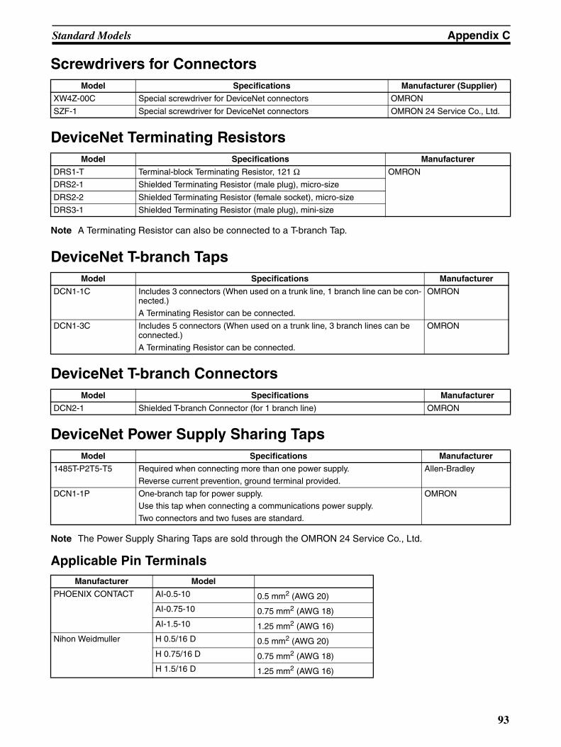
Standard Models Appendix C
Screwdrivers for Connectors
DeviceNet Terminating Resistors
Note A Terminating Resistor can also be connected to a T-branch Tap.
DeviceNet T-branch Taps
DeviceNet T-branch Connectors
DeviceNet Power Supply Sharing Taps
Note The Power Supply Sharing Taps are sold through the OMRON 24 Service Co., Ltd.
Applicable Pin Terminals
Model Specifications Manufacturer (Supplier)
XW4Z-00C Special screwdriver for DeviceNet connectors OMRON
SZF-1 Special screwdriver for DeviceNet connectors OMRON 24 Service Co., Ltd.
Model Specifications Manufacturer
DRS1-T Terminal-block Terminating Resistor, 121 Ω OMRON
DRS2-1 Shielded Terminating Resistor (male plug), micro-size
DRS2-2 Shielded Terminating Resistor (female socket), micro-size
DRS3-1 Shielded Terminating Resistor (male plug), mini-size
Model Specifications Manufacturer
DCN1-1C Includes 3 connectors (When used on a trunk line, 1 branch line can be con-nected.)
A Terminating Resistor can be connected.
OMRON
DCN1-3C Includes 5 connectors (When used on a trunk line, 3 branch lines can be connected.)
A Terminating Resistor can be connected.
OMRON
Model Specifications Manufacturer
DCN2-1 Shielded T-branch Connector (for 1 branch line) OMRON
Model Specifications Manufacturer
1485T-P2T5-T5 Required when connecting more than one power supply.
Reverse current prevention, ground terminal provided.
Allen-Bradley
DCN1-1P One-branch tap for power supply. Use this tap when connecting a communications power supply.
Two connectors and two fuses are standard.
OMRON
Manufacturer Model
PHOENIX CONTACT AI-0.5-10 0.5 mm2 (AWG 20)
AI-0.75-10 0.75 mm2 (AWG 18)
AI-1.5-10 1.25 mm2 (AWG 16)
Nihon Weidmuller H 0.5/16 D 0.5 mm2 (AWG 20)
H 0.75/16 D 0.75 mm2 (AWG 18)
H 1.5/16 D 1.25 mm2 (AWG 16)
93

Standard Models Appendix C
94
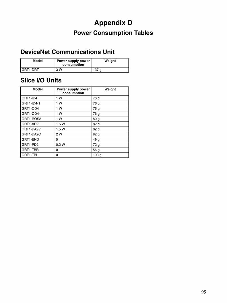
Appendix DPower Consumption Tables
DeviceNet Communications Unit
Slice I/O Units
Model Power supply power consumption
Weight
GRT1-DRT 3 W 137 g
Model Power supply power consumption
Weight
GRT1-ID4 1 W 76 g
GRT1-ID4-1 1 W 76 g
GRT1-OD4 1 W 76 g
GRT1-OD4-1 1 W 76 g
GRT1-ROS2 1 W 80 g
GRT1-AD2 1.5 W 82 g
GRT1-DA2V 1.5 W 82 g
GRT1-DA2C 2 W 82 g
GRT1-END 0 49 g
GRT1-PD2 0.2 W 72 g
GRT1-TBR 0 56 g
GRT1-TBL 0 108 g
95

Power Consumption Tables Appendix D
96

Appendix EI/O Current Consumption
Model Current consumption
GRT1-ID4 33 mA
GRT1-ID4-1 33 mA
GRT1-OD4 12 mA
GRT1-OD4-1 12 mA
GRT1-ROS2 30 mA
GRT1-AD2 0 mA
GRT1-DA2V 0 mA
GRT1-DA2C 0 mA
GRT1-END 0 mA
GRT1-PD2 4 mA
GRT1-TBR 0 mA
GRT1-TBL 4 mA
97

I/O Current Consumption Appendix E
98

GlossaryThe following table provides a list of commonly used DeviceNet terms.
Term Explanation
Bus OFF Indicates that the error rate in the network is extremely high. Errors are detected when a fixed threshold is exceeded by the internal error counter. (The internal error counter is cleared when the Master Unit is started or restarted.)
CAN CAN is short for Controller Area Network. It is a communications protocol developed as a LAN for use in automobiles. DeviceNet employs CAN technology.
Configurator A device for setting the system settings. The Configurator can read ID information, read and write parameters, and display the network configuration.OMRON’s DeviceNet Configurator is designed for use with an OMRON Master Unit.
Consumed Connection Size Indicates the data size (byte length) received via the connection.
ODVA ODVA is short for Open DeviceNet Vendors Association, Inc. It is a non-profit organization formed by machine vendors with the aim to administer and popularize the DeviceNet specification.
Produced Connection Size Indicates the data size (byte length) sent via the connection.
Connection This is a logical communications channel for facilitating communications between nodes. Communications are maintained and managed between the master and slaves.
Device Profile Standardizes the configuration and behavior (the smallest data configuration and opera-tion that must be supported by the devices) of devices of the same type. Provides mutual exchangeability between devices of the same type. Also known as a device model. Devices for which device profiles are currently being studied include sensors, valves, dis-play units, and encoders.
Master/Slave A node can be either a master, which collects and distributes data, or a slave, which out-puts and inputs data according to the instructions received from the master. OMRON’s DeviceNet products are already provided with either master or slave functions in a pre-defined master/slave connection set.
99

Glossary
100

Index
Ccables
communications cables, xix
models, 91
precautions, xviii, xix
changing present values, xvii
circuits
precautions, xviii
comments
Slave comments, 32
communications
errors
history monitor, 34
starting, 57
Configurator
reading communications error history, 34
writing maintenance dates, 37
connectors
models, 92
precautions, xviii
crimp terminals, xviii
models, 92
DDeviceNet
explicit messages, 77
EEC Directives, xix
Environment-resistive Slaves
precautions, xvii
FFALS instruction, xvi
fixed I/O allocations
precautions, 59
GGeneral-purpose Slaves
precautions, xvii
grounding
precautions, xviii
II/O tables
for Masters, 57
indicators
status, 60
Mmaintenance, 37
writing maintenance dates, 37
NNetwork Power Voltage Error Flag, 29
Ooutputs
precautions, xvii
Ppacking
precautions, xix
power supply
communications power supply, xviii
network voltage monitor, 29
precautions, xviii
Power Supply Sharing Taps
models, 93
precautions
application, xviii
cables, xviii, xix
circuits, xviii
connectors, xviii
EC Directives, xix
environment, xvii
general, xvi
grounding, xviii
packing, xix
power supply, xviii
safety, xvi
scan list, xix
switches, xviii
wiring, xviii
Programming Console
creating I/O tables, 58
101

Index
Rrefreshing
data, xvii
Sscan lists
creating, 58
precautions, xix
registering, 59
screwdrivers
models, 93
slave comments, 32
switches
rotary switches
precautions, xviii
software switches, 59
TT-branch Connectors
models, 93
T-branch Taps
models, 93
Terminating Resistors
models, 93
transferring I/O memory data, xvii
transferring I/O memory files, xvii
UUnit Maintenance Flag, 30
user I/O allocations
precautions, 59
Wwiring
precautions, xviii
102

Revision History
A manual revision code appears as a suffix to the catalog number on the front cover of the manual.
The following table outlines the changes made to the manual during each revision. Page numbers refer to theprevious version.
Revision code Date Revised content
01 November 2005 Original production
02 May 2006 Page xx: Addition made to item 2 at the top of the page. Page 2: Callout for Slice I/O Unit changed.Page 4: Callouts in System Configuration changed. Page 4: Communications distance deleted from the Communications Specifi-cations table.Pages 5: Number of I/O points clarified in table. Page 6: Entry for the connector and power consumption per block changed in and two rows added to table. Page 6: Slice I/O Units added to the Available Units table. Page 10: Dimensions graphic replaced. Page 21: Table changed. Page 26: Note 2 changed. Page 45: Tables moved to appendix, text adjusted accordingly, and note 2 changed. Page 46: Callout regarding power supply added to the Wiring Example dia-gram.Page 47: Model numbers for recommended power supply changed. Page 50: First paragraph in section 3-4-1 changed. Pages 65 and 66: Corrected Multiple I/O Terminal processing time to Smart-Slice processing time. Page 76: Left cells in third and fourth rows of table in section 6-4 changed.Page 83: Corrected Contents (Hex) for D0001 under Contents of C from 00 09 to 00 0C. Page 93: Slice I/O Units added to table. Page 97: Two appendices added.
03 April 2008 Page 6: Added accessories row to table.Page 49: Added information on connectors and deleted precautions section.Page 56: Deleted model number and illustration from note. Page 80: Changed size of reponse. Page 94: Changed table of Phoenix Contact products.
Cat. No. W454-E1-03
Revision code
103