gs1 bar code verification process - home | gs1 - the global
TRANSCRIPT
1D Barcode Verification Process Implementation Guideline
This implementation guideline provides instructions for creating a consistent verification service for testing barcode quality as well as data integrity
Release 24.1, Ratified, Jul 2015

1D Barcode Verification Process Implementation Guideline
Release 24.1, Ratified, Jul 2015 © 2015 GS1 AISBL Page 2 of 44
Document Summary Document Item Current Value
Document Name 1D Barcode Verification Process Implementation Guideline
Document Date Jul 2015
Document Version 24
Document Issue 1
Document Status Ratified
Document Description This implementation guideline provides instructions for creating a consistent verification service for testing barcode quality as well as data integrity
Contributors Name Organisation
Alan Gormley GS1 Ireland
Alice Mukaru GS1 Sweden
Andreas Fuessler GS1 Germany
Andrew Hearn GS1 Global Office
Anne-Sophie Meurant GS1 Belgium & Luxembourg
Benjamin Ostman GS1 Finland
Cedric Houlette GS1 France
Christine Hanko GS1 Hungary
Chuck Biss GS1 Global Office
Daniel Clark GS1 Canada
Daniel Muller GS1 Switzerland
Elzbieta Halas GS1 Poland
Eugen Sehorz GS1 Austria
Frank Sharkey GS1 Global Office
Gerald Gruber GS1 Austria
Greg Rowe GS1 Global Office
Heinz Graf GS1 Switzerland
Ilka Machemer GS1 Germany
Ilteris Oney GS1 Global Office
James Chronowski GS1 US
John Lane GS1 Australia
Karen Moritz GS1 Australia
Karolin Harsanji GS1 Sweden
Lionel Willig GS1 France
Marianna Revallova GS1 Slovakia
Mark Frey GS1 GO –Facilitator for ID SMG

1D Barcode Verification Process Implementation Guideline
Release 24.1, Ratified, Jul 2015 © 2015 GS1 AISBL Page 3 of 44
Log of Changes Release Date of Change Changed By Summary of Change
1 April 19, 2012 Andrew Hearn Document creation
2 April 25, 2012 Andrew Hearn Updates based upon feedback
3 June 1, 2012 Andrew Hearn To consolidate team feedback
4 June 6, 2012 Andrew Hearn To consolidate team feedback
5 June 18, 2012 Andrew Hearn To consolidate team feedback
6 July 16, 2012 Andrew Hearn Updates based upon conference call and emailed feedback from the team
7 July 18, 2012 Andrew Hearn Process feedback from conference calls
8 July 19, 2012 Andrew Hearn Updates based upon conference call
9 July 20, 2012 Andrew Hearn Process feedback from conference calls
10 July 26, 2012 Andrew Hearn Updates from conference call comment resolution
11 July 30, 2012 Andrew Hearn Updates from conference call comment resolution
12 August 6, 2012 Andrew Hearn Updates from conference call comment resolution
13 August 16, 2010 Andrew Hearn Updates from conference call comment resolution
14 September 24, 2012 Andrew Hearn Updates from conference call comment resolution
15 October 2, 2012 Andrew Hearn Update text from email feedback
16 October 4, 2012 Andrew Hearn Updates from conference call comment resolution
17 October 5, 2012 Andrew Hearn Minor updates from emails
18 October 9, 2012 Andrew Hearn Updates from SMG review during I&S Event in Dublin
19 August 7, 2013 Andrew Hearn Add Draft Appendix for Scenarios
20 August 14, 2013 Andrew Hearn Updated Scenarios
21 August 21, 2013 Andrew Hearn Updated document title
22 April 25, 2014 Andrew Hearn Updated document to address Public Review comments
23.1 July 2015 Valerie Hoste Applied new GS1 branding prior to publication
Disclaimer GS1®, under its IP Policy, seeks to avoid uncertainty regarding intellectual property claims by requiring the participants in the Work Group that developed this 1D Barcode Verification Process Implementation Guideline to agree to grant to GS1 members a royalty-free licence or a RAND licence to Necessary Claims, as that term is defined in the GS1 IP Policy. Furthermore, attention is drawn to the possibility that an implementation of one or more features of this Specification may be the subject of a patent or other intellectual property right that does not involve a Necessary Claim. Any such patent or other intellectual property right is not subject to the licencing obligations of GS1. Moreover, the agreement to grant licences provided under the GS1 IP Policy does not include IP rights and any claims of third parties who were not participants in the Work Group.
Accordingly, GS1 recommends that any organisation developing an implementation designed to be in conformance with this Specification should determine whether there are any patents that may encompass a specific implementation that the organisation is developing in compliance with the Specification and whether a licence under a patent or other intellectual property right is needed. Such a determination of a need for licencing should be made in view of the details of the specific system designed by the organisation in consultation with their own patent counsel.
THIS DOCUMENT IS PROVIDED “AS IS” WITH NO WARRANTIES WHATSOEVER, INCLUDING ANY WARRANTY OF MERCHANTABILITY, NONINFRINGMENT, FITNESS FOR PARTICULAR PURPOSE, OR ANY WARRANTY OTHER WISE ARISING OUT OF THIS SPECIFICATION. GS1 disclaims all liability for any damages arising from use or misuse of this Standard, whether special, indirect, consequential, or compensatory damages, and including liability for infringement of any intellectual property rights, relating to use of information in or reliance upon this document.

1D Barcode Verification Process Implementation Guideline
Release 24.1, Ratified, Jul 2015 © 2015 GS1 AISBL Page 4 of 44
GS1 retains the right to make changes to this document at any time, without notice. GS1 makes no warranty for the use of this document and assumes no responsibility for any errors which may appear in the document, nor does it make a commitment to update the information contained herein.
GS1 and the GS1 logo are registered trademarks of GS1 AISBL.

1D Barcode Verification Process Implementation Guideline
Release 24.1, Ratified, Jul 2015 © 2015 GS1 AISBL Page 5 of 44
Table of Contents 1 Introduction ................................................................................................. 7
1.1 Scope and Purpose .......................................................................................................... 7
2 Target Audience ............................................................................................ 8
3 Process Overview ......................................................................................... 8 3.1 Process Workflow ............................................................................................................ 9
4 Procedures / Activities ............................................................................... 10 4.1 Calibrate and Maintain Equipment ................................................................................... 10 4.2 Receive Requests and Product Samples ........................................................................... 10 4.3 Example of GS1 Barcode Verification Request ................................................................... 11 4.4 Record requests and sample details ................................................................................. 11 4.5 Verify the barcode quality and conformance ..................................................................... 12
4.5.1 Overview of Verifying the Barcode .......................................................................... 12 4.6 Issue Reports of Quality and Conformance Verification ....................................................... 24
4.6.1 Writing the report ................................................................................................. 24 4.7 Publish the Conformance Assessment Results ................................................................... 25 4.8 Send Reports, Samples (If Applicable) ............................................................................. 25 4.9 Follow Up ..................................................................................................................... 25
5 Conformance Clauses .................................................................................. 25 5.1 Measures and Tolerances ............................................................................................... 25 5.2 How to Use it? .............................................................................................................. 26
A Dealing with symbols with borderline grades ............................................. 27
B Special Points of Attention .......................................................................... 29 B.1.1 Checklist ...................................................................................................................... 29 B.1.2 Frequently Asked Questions ........................................................................................... 29
C Reference materials .................................................................................... 30
D Using traditional measurements as part of quality ..................................... 31 D.1.1 Print Contrast Signal and tolerances ................................................................................ 31 D.1.2 Scan reflective profile (traditional measurements) ............................................................. 31
E Grade thresholds for scan reflectance parameters ...................................... 32
F Use of Calibrated Conformance Standard Test Card (CCSTC) ...................... 33
G The process of symbol generation .............................................................. 36
1D Barcode Verification Process Implementation Guideline
Release 24.1, Ratified, Jul 2015 © 2015 GS1 AISBL Page 6 of 44
H GS1 Barcode Verification Template .......................................................................... 38
I Glossary of terms ........................................................................................ 40
J Scenarios and Comments ............................................................................ 41

1D Barcode Verification Process Implementation Guideline
Release 24.1, Ratified, Jul 2015 © 2015 GS1 AISBL Page 7 of 44
1 Introduction Today, 100% reliable GS1 Barcodes are an absolutely vital part of the supply chain. Hundreds of thousands of companies around the world rely on GS1 standards to conduct business and meet consumers’ expectations. That means that if a barcode cannot be properly decoded or is scanned with a delay it's more than just time at the cash register or the warehouse that is lost. Every time a human has to manually enter data into a system there is potential for error as well as delay. Inaccurate sales data affects reordering and inaccuracies in the receipts and despatches from a warehouse mean that items are ‘lost’ in the supply chain or that items appear to exist that are not really there. Each single case is perhaps small but the cumulative effect is very large.
As a result users around the world increasingly require that the barcodes on the products they purchase conform to GS1 standards. A barcode verification service provides neutral evaluation of barcodes and helps to ensure better reading rates thus supporting the drive for accuracy and efficiency of barcode scanning.
This document, combined with “Starting and Maintaining a Linear GS1 Barcode Verification Service”, will provide Member Organisations with the framework to deliver a GS1 Barcode Verification process that will ensure that GS1 Barcodes are being verified in a systematic and consistent way worldwide. This increases confidence, helps to establish credibility and inspires assurance that products in conformance to GS1 standards will perform as intended.
1.1 Scope and Purpose Awareness and understanding of overall linear barcode quality, and the complete process to determine and understand it, can have many benefits to the users of barcode driven AIDC (Automatic Identification and Data Capture) systems.
A Member Organisation (MO) may be asked to carry out verification for one or both of the following purposes;
■ To test the individual GS1 Barcodes on a product for compliance – testing the barcodes. This will usually be requested at the packaging design stage of a product’s life cycle
■ To test whether a completed product ready for market is identified with GS1 Identification Key(s) and GS1 Barcode(s) that comply with GS1 standards. This will typically be requested when the product is manufactured and ready for despatch. The requesting parties may need the report to satisfy a customer that the product will flow smoothly through the customer’s distribution channels
The practices to be followed when testing the barcode should be carefully considered in consultation with major users of the GS1 System in the MOs country. The consequences of a ‘fail’ GS1 verification report on a completed product may be very serious for manufacturers if customers refuse to accept shipments because of doubt about the GS1 Barcodes or the associated data. A Verification Service measures only the data integrity and the quality of the barcode(s) that are submitted for testing and does not ensure the quality of all barcodes produced; therefore it is recommended that regular testing be conducted to ensure the quality of the symbols that are being created.
This implementation guide provides instructions for creating a consistent verification service for testing barcode quality as well as data integrity. This will include guidance on the minimum recommended requirements and basic items including:
■ creation of procedures / guidelines,
■ recommended basic reference documents and guides,
■ illustration of scenarios with Pass-Fail grade symbols
This general framework will also provide further practical guidance through example and reference to published standards, existing reference material and procedures that will give greater detail in the practical, operational and educational aspects of barcode quality determination.
Whereas this manual concentrates on the testing of barcode verification, please refer to the implementation guideline “Starting and Maintaining a Linear GS1 Barcode Verification Service” for setting up the barcode verification service.

1D Barcode Verification Process Implementation Guideline
Release 24.1, Ratified, Jul 2015 © 2015 GS1 AISBL Page 8 of 44
The GS1 General Specifications are the reference source for all standards related questions and are referred to frequently within this guideline. Note that the GS1 General Specifications are updated on a yearly publications cycle and it is important that the latest version be utilised by the Barcode Verification Teams.
Important: Overall "barcode and data quality" is much more than just "print quality" (as measured by a verification device). There is great benefit in looking at the whole picture of quality and gaining the knowledge and understanding of what these checks, tests and results can provide in the way of practical diagnostic advice to improve overall compliance with GS1 standards.
EXAMPLE:
■ Pure Barcode Verification Test Result: Your print quality failed with 1.4/06/670
■ Barcode Verification Best Practice: Your overall print quality failed with 1.4/06/670. The failure was a low contrast grade which was due to the background substrate having a low reflectance. We recommend you change the substrate material to a ‘whiter’ version. This will increase the overall symbol quality and ensure good scan rates in the future.
This document was developed under the ISO/IEC Guide 67:2004 and specifies the minimum process and requirements to assess conformity and declare products identified with linear GS1 Barcodes in conformance to GS1 standards.
The sole aim is to provide a common methodology and criteria for GS1 Member Organisations to perform conformity assessment or verification services of GS1 Barcodes according to GS1 practices and requirements. This guideline is focused on linear barcodes only; the procedures for assessing / testing 2D GS1 Symbols are contained in a separate document.
All requirements described in this document are generic and are intended to be applicable to all organisations.
2 Target Audience The target audience is GS1 Member Organisation staff involved in GS1 Barcode Quality and Conformance Verification. It is hoped that the information contained will be of use as a basis for training and/or reference material for [expert] end-users involved in GS1 Barcode production, print quality control and conformance assessment.
3 Process Overview The Barcode Verification process should comprise of the following high level steps;
1. Record of receipt of the sample(s)
2. Record of data associated to a barcode (in a database)
3. Verify the Barcode
4. Perform the additional tests on the Barcode
5. Create and send Barcode Verification Report
6. Ensure availability of the Verification Report (if available, keep the sample(s) for a minimum of 2 years (suggestion)
In the sections below, the broad requirements for each of these process steps is expanded. However, for services that test many barcodes, it is recommended to create an automated system, supported by a detailed work-flow. This helps to ensure consistency of the testing process and is of particular importance when testing is conducted by multiple staff members.

1D Barcode Verification Process Implementation Guideline
Release 24.1, Ratified, Jul 2015 © 2015 GS1 AISBL Page 9 of 44
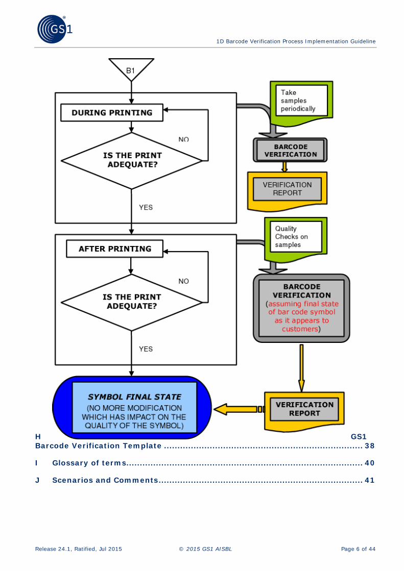
3.1 Process Workflow
3.2.3. Record request and sample’s details
3.2.5. Verify the Barcode Quality and Conformance
Ask for adjustments
Start
3.2.1. Calibrate equipment
3.2.2. Receive requests and product samples
Is the request valid and
complete?
3.2.6. Generate reports of quality
Does the barcode
conform to GS1
3.2.8. Publish the Conformance Assessment
Results, if applicable
End
NO
NO
YES
YES
3.2.10. Aid Member with corrective action, if
requested
3.2.7. Send report, Return samples (if requested)

1D Barcode Verification Process Implementation Guideline
Release 24.1, Ratified, Jul 2015 © 2015 GS1 AISBL Page 10 of 44
4 Procedures / Activities
4.1 Calibrate and Maintain Equipment The staff member who is conducting the testing (referred to as ‘tester’ from this point on) shall follow all recommendations provided from the equipment’s manufacturer to install, use, maintain, operate and calibrate equipment, especially regarding the extent and frequency of maintenance and calibration.
Regular re-calibration, at least as frequently as recommended by the manufacturer or, if there is no guide, at least once a month, shall be done in order to provide reference values of colour and contrast to the equipment. Typically re-calibration should occur at regular intervals in line with the manufacturer’s recommendation, or after a substantial period of inactivity, or whenever there is an environmental change such as lighting conditions. The verifier must always be recalibrated if the scan head, the measuring aperture, or scan width is changed.
A calibration card provided by the verifier manufacturer should be used. It should be traceable and replaced periodically, following the manufacturer's recommendation, or earlier if deterioration of the card is noticed. A test of calibration conformance should be done, at least annually. This test can be done using a Use of a Calibrated Conformance Standard Test Card, available from GS1 US or by the equipment manufacturer. This test confirms that the verifier is responding correctly to its routine calibrations Results of tests, calibration and maintenance reports of equipment used on the assessment process must be identified and safeguarded for at least two years.
4.2 Receive Requests and Product Samples The tester shall make clear the conditions and pre-requirements to perform the assessment process (eg.: A Member Organisation may or may not require the submitter to be a Member). The tester shall make clear what/if any fees will be charged to assess conformance and the procedures to provide it.
At least the following information should be provided with the request for a test:
■ Company Name
■ Contact Details (Name, Position, Address, Telephone Number, e-mail)
■ List of products or labels to be assessed.
■ Order Number (if applicable)
■ Whether the samples are to be returned after testing
■ Whether products are confidential (you will need to handle them so that visitors to your office, cleaners etc. will not see them)
To be assessed, a product (samples) should preferably be submitted full and complete in its final form, which allows extensive testing in terms of colour, contrast, location and quality. Sometimes it is recommended to have barcodes in layout versions, e.g. proofs tested to avoid delays in supply and additional costs
The verification/assessment body must check if all the requested information about product and submitter was received. If all of the requested information has not been received, the tester will contact the submitter to gather all of the necessary information.
1D Barcode Verification Process Implementation Guideline
Release 24.1, Ratified, Jul 2015 © 2015 GS1 AISBL Page 11 of 44
4.3 Example of GS1 Barcode Verification Request
GS1 Barcode Verification Request Form
Date of Submission:………………………………………………………………………….
Global Location Number or GS1 Company Prefix (if known): ……………………………………………………….
Company Name…………………………………..………………………………………………..
Company Address: …………………………..………………………………………………..
Contact Name: ……………………………………………………………………………………..
Phone Number: ………………………………………………………….………………………..
Email Address: ………………………………………………………….…………………………
Urgent Date Required: …………………………………………………………………………
Total Number of samples submitted: ______
We will be collecting the samples after they have been completed: Yes / No
Note: All samples will be disposed of within 7 days of report being issued unless specified. You will be advised when your products are ready for collection. Collection must be within two weeks of this notification.
4.4 Record requests and sample details Upon receipt, the details required for the testing report should be captured in an appropriate system. As a minimum this shall include all details required for the completion of the GS1 Barcode Verification Report (Name and contact details of the submitter, GTIN, date of receipt) and ideally this can be requested on a ‘GS1 Barcode Verification Request Form’.
The tester shall establish systems and procedures for the identification, collection, indexing, accessing, storage, maintenance and disposal of documents and samples provided by the submitter. The procedures shall define the controls needed to prevent the unintended use of obsolete documents. The tester shall guarantee the confidentiality of documents, samples or any information provided.
The maximum period to assess conformity of a product should be established and notified to the submitters. The form in which the product is tested should be recorded.
The following list indicates the desirability of testing conditions for barcodes:
■ Product complete, filled, packaged, ready for market
■ Empty package
■ Label only
■ Model or mock-up of product in authentic colours
■ Artwork in authentic colours printed and supplied by user
■ Artwork in black and white printed and supplied by user
■ Artwork in authentic colours printed by MO from image supplied by user
■ Artwork in black and white printed by MO from image supplied by user
■ MOs must use policies and processes that aim to have samples sent to them in the highest condition that circumstances and the nature of the product allow.
Where artwork is tested the MO must have protocols to ensure that testers are aware of the actual size at which the barcode involved will be printed.

1D Barcode Verification Process Implementation Guideline
Release 24.1, Ratified, Jul 2015 © 2015 GS1 AISBL Page 12 of 44
Where only a label is sent every effort must be made to discover where the barcode will appear on the finished product e.g. artwork, photograph. If location cannot be assessed the report is to indicate “not assessed” for location.
The verification/assessment body must check if all the requested information about product and submitter was received.
4.5 Verify the barcode quality and conformance The barcode shall only be verified using an ISO compliant verifier operated by trained staff. The results should be transferred to the GS1 Barcode Verification Report. Ideally this would be done automatically by linking the verifier to a database that enables automatic population of required data report.
The tester must set on the Barcode Quality Verifier the appropriate aperture/light source if necessary (in most verifiers this is fixed). The symbol shall be measured by at least 10 (ten) scans at different heights.
The results of the equipment evaluations and the analysis (visual check) by the tester shall be compared with the applicable Conformance Clauses for GS1 Barcodes to ensure that all mandatory requirements are fulfilled. All relevant GS1 Conformance Clauses must be assessed such as: Height, X-dimension (size), data encodation, print quality, symbol placement.
ISO compliant verifiers provide a series of results that are available to the tester, this document provides details on how to interpret many of those results.
4.5.1 Overview of Verifying the Barcode
There are four results that can occur when making assessments of the GS1 Barcode submitted for testing, these are:
■ The barcode meets the GS1 standards: GS1 Barcode Verification Report is marked PASS
■ The barcode does not meet the GS1 standards: GS1 Barcode Verification Report is marked FAIL with relevant comments
■ The barcode meets the GS1 standards: GS1 Barcode Verification Report is marked PASS. However, there are some parameters not assessed with comments at the relevant parameter(s). Generally this applies to artwork submitted for pre-checking prior to printing the final barcode
■ The barcode does not meet the GS1 standards: GS1 Barcode Verification Report is marked FAIL. However, has some parameters not assessed with comments at the relevant parameter(s). Generally this applies to artwork submitted for pre-checking prior to printing the final barcode

1D Barcode Verification Process Implementation Guideline
Release 24.1, Ratified, Jul 2015 © 2015 GS1 AISBL Page 13 of 44
Table 4-1 Parameters Parameters tested Meets General Specifications GS1 Barcode Verification Report
All Yes Pass
No with comments Fail
Some Yes with comments Pass
No with comments Fail
Important: A barcode that fails on multiple parameters may suffer from many different problems making it impossible for the verifier to make an accurate analysis of the problem. In such cases it is recommended to stop the testing and inform the submitter of the fail and point to generic documents on how to print quality barcodes. Some degree of analysis based on visual inspection will normally be possible and the results of this should be given to the submitter (e.g. blurred bar edges, too small, dull background etc.)
4.5.1.1 Reporting Linear Symbol Grade
The print quality of barcodes may vary over the height of the symbol. In particular localised defects and variations in symbol characteristics may occur, resulting in the likelihood of scan reflectance profiles from different scan paths across the symbol differing significantly. For this reason it is necessary to assess the overall symbol quality by averaging scan reflectance profile grades from ten scan paths ideally taken in ten equal steps over the entire height of the symbol.
Figure 4-1 Overall symbol grade is based on average of at least ten scans
The overall symbol grade is the arithmetic mean of at least 10 individual grades expressed to one decimal point. It must always be reported using the ISO quality specification expressed as g.g/aa/www, where:
■ g.g is the minimum overall symbol grade to one decimal place (on a 4.0 scale)
■ aa is a two digit reference number that approximates to the measuring aperture in thousandths of an inch
■ www is the wavelength of the light source in nanometres
■ The overall symbol grade is the average of at least ten individual scan grades and is the only indicator of grade that should be read when considering whether the barcode has passed or failed for ISO grade
4.5.1.2 Administration of samples and records
MOs conducting verification tests shall have defined processes.
5 4 1 2 3 4 5 6 7 8 9 0 8 >5 4 1 2 3 4 5 6 7 8 9 0 8 >5 4 1 2 3 4 5 6 7 8 9 0 8 >
At least 10 scans per symbol for vertical redundancy as well
as for statistical stability

1D Barcode Verification Process Implementation Guideline
Release 24.1, Ratified, Jul 2015 © 2015 GS1 AISBL Page 14 of 44
4.5.1.3 Conducting the test
4.5.1.3.1 Examine the sample to assess
■ Suitability for testing (per desirability of testing above)
■ Barcode symbology
4.5.1.3.2 Examine the sample to assess the following parameters against the relevant GS1 specification/recommendation
■ Correct symbology choice for the intended scanning environment
■ X-dimension
■ Height
■ Quiet Zones
■ Human Readable Interpretation (HRI)
□ All the HRI data is completed
□ Encoded data matches the Human Readable Interpretation (HRI) data
■ Location
■ GTIN and / or correct use of GS1 Application Identifier(s) and associated data
4.5.1.3.3 Ensure that the verifier’s input device (scanner, scan head) has the correct aperture size
Table 4-2 Verifier aperture sizes and required grades for linear GS1 symbologies Symbology Aperture (mil) Required Grade (Minimum)
EAN-8, EAN-13, UPC-A, UPC-E 6 C (1.5/06/670)
GS1 DataBar 6 C(1.5/10/670)
GS1-128 10 C(1.5/10/670)
GS1-128, Coupon Extended Codes 6 C(1.5/10/670)
ITF-14 ≥ 0.635mm (0.025 in.)X 20 D(0.5/20/670)
ITF-14 < 0.635mm (0.025 in.)X 10 C(1.5/10/670)
A verification test must be performed with the light source and verifier aperture size. The scanners (input devices scan heads) on most verifiers have a built-in light source that the operator cannot adjust but where it can be adjusted it should be set to 670 nanometers +/- 10.
Aperture size is automatically selected by some verifiers but where manual selection is required operators must be careful to ensure that they perform tests with the correct aperture.
4.5.1.3.4 Preparation for testing
■ Ensure the verifier is ready for use
■ Batteries (where used) charged
■ Correct accessories (scanners) fitted where appropriate
■ Settings correct for the test to be performed
■ Power source available
■ Work space suitable for handling the samples and performing the test

1D Barcode Verification Process Implementation Guideline
Release 24.1, Ratified, Jul 2015 © 2015 GS1 AISBL Page 15 of 44
4.5.1.3.5 Calibrate the verifier
The verifier should be calibrated by following the manufacturer’s recommended process for calibration. Each manufacturer may have a different process that needs to be followed based upon the specific model that is being used.
4.5.1.3.5.1 Importance of calibration
The scan reflectance profile is a plot of reflectance variations across the symbol, from which all the other calculations are made. The verifier must, therefore, measure reflectance accurately. It is extremely important to ensure that the instrument is properly calibrated – in other words that its reflectance measurements are matched to the known reflectance of the calibration card or test symbol provided by the equipment supplier. Not only does this ensure correct grading, but also consistency and repeatable measurement. Inadequate calibration will either prevent operation of the instrument, or lead to strange results and varying quality grades.
4.5.1.3.5.2 Calibration Frequency
Verifier manufacturers always provide calibration instructions. It is absolutely vital that these calibration instructions are followed. It is not sufficient only to calibrate the verifier when it is first installed and activated. If manual calibration is performed, it should be done under the same environmental conditions used for the grading of barcodes under test. For maximum consistency, regular re-calibration, at least as frequently as recommended by the manufacturer, is recommended. Typically re-calibration should occur at regular intervals in line with the manufacturer’s recommendation, or after a substantial period of inactivity, or whenever there is an environmental change such as lighting conditions. The verifier must always be recalibrated if the scan head, the measuring aperture, or scan width is changed.
4.5.1.3.5.3 Calibration materials
Most manufacturers provide calibration materials that have accurately specified reflectance characteristics. Care of these materials, which may be either a test symbol or a ceramic or enamel reflectance tablet is extremely important. Packaging and storage of the materials must be in accordance with the manufacturer’s instructions. Prompt return of the materials, after use, to their safe storage area is key to their continued reliability.
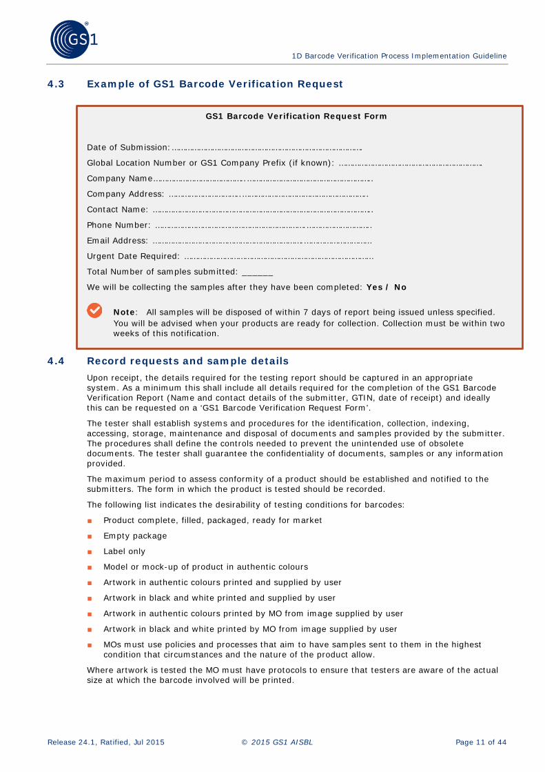
4.5.1.3.5.4 Calibrated Conformance test
Calibration is appropriate for routine verifier use but periodically a calibration conformance test should be carried out. This will test whether the verifier is responding correctly to routine calibrations and therefore producing accurate results. It will also reveal any deterioration in the calibration materials – cards or tiles – that are used and may indicate any operator faults that affect results. Some verifier manufacturers offer annual calibration conformance testing on their equipment and will take it back to their premises for the purpose. Other verifier users may need to engage their equipment supplier to do the tests or may do the tests themselves.
The decision on how to perform calibration conformance testing and how often should be made in conjunction with the equipment supplier. It is a very important test and should not be overlooked. A verifier that appears to be functioning normally may in fact produce incorrect results if it has not been successfully tested for calibration conformance.
For those choosing to perform the tests themselves, GS1 provides Calibrated Conformance Test cards, produced and measured to a high degree of accuracy, enabling users to check that the readings obtained on their equipment are consistent and accurate (see F, Use of Calibrated Conformance Standard Test Card for full details of the test cards).
1D Barcode Verification Process Implementation Guideline
Release 24.1, Ratified, Jul 2015 © 2015 GS1 AISBL Page 16 of 44
Figure 4-2 Calibrated Conformance Standard Test Card
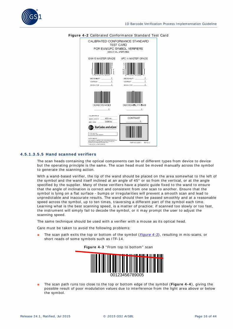
4.5.1.3.5.5 Hand scanned verifiers
The scan heads containing the optical components can be of different types from device to device but the operating principle is the same. The scan head must be moved manually across the symbol to generate the scanning action.
With a wand-based verifier, the tip of the wand should be placed on the area somewhat to the left of the symbol and the wand itself inclined at an angle of 45° or so from the vertical, or at the angle specified by the supplier. Many of these verifiers have a plastic guide fixed to the wand to ensure that the angle of inclination is correct and consistent from one scan to another. Ensure that the symbol is lying on a flat surface - bumps or irregularities will prevent a smooth scan and lead to unpredictable and inaccurate results. The wand should then be passed smoothly and at a reasonable speed across the symbol, up to ten times, traversing a different part of the symbol each time. Learning what is the best scanning speed, is a matter of practice; if scanned too slowly or too fast, the instrument will simply fail to decode the symbol, or it may prompt the user to adjust the scanning speed.
The same technique should be used with a verifier with a mouse as its optical head.
Care must be taken to avoid the following problems:
■ The scan path exits the top or bottom of the symbol (Figure 4-3), resulting in mis-scans, or short reads of some symbols such as ITF-14.
Figure 4-3 “From top to bottom” scan
00123456789005
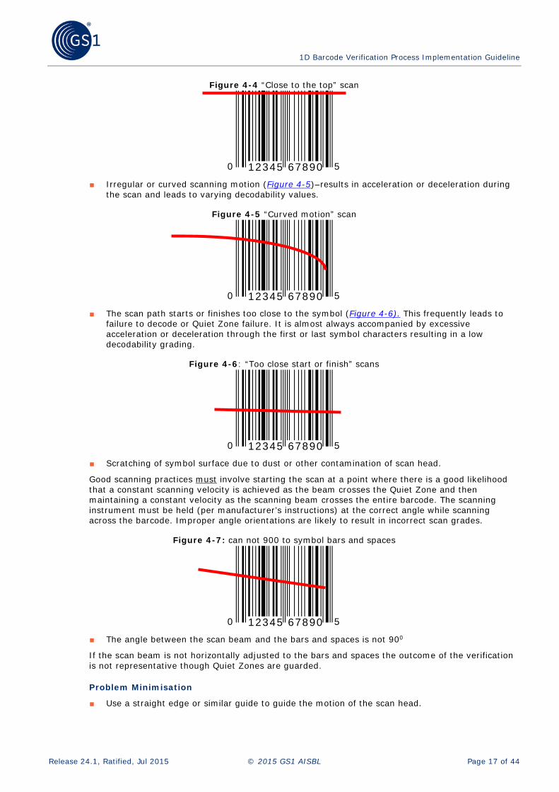
■ The scan path runs too close to the top or bottom edge of the symbol (Figure 4-4), giving the possible result of poor modulation values due to interference from the light area above or below the symbol.
1D Barcode Verification Process Implementation Guideline
Release 24.1, Ratified, Jul 2015 © 2015 GS1 AISBL Page 17 of 44
Figure 4-4 “Close to the top” scan
■ Irregular or curved scanning motion (Figure 4-5)–results in acceleration or deceleration during
the scan and leads to varying decodability values.
Figure 4-5 “Curved motion” scan
■ The scan path starts or finishes too close to the symbol (Figure 4-6). This frequently leads to
failure to decode or Quiet Zone failure. It is almost always accompanied by excessive acceleration or deceleration through the first or last symbol characters resulting in a low decodability grading.
Figure 4-6: “Too close start or finish” scans
■ Scratching of symbol surface due to dust or other contamination of scan head.
Good scanning practices must involve starting the scan at a point where there is a good likelihood that a constant scanning velocity is achieved as the beam crosses the Quiet Zone and then maintaining a constant velocity as the scanning beam crosses the entire barcode. The scanning instrument must be held (per manufacturer’s instructions) at the correct angle while scanning across the barcode. Improper angle orientations are likely to result in incorrect scan grades.
Figure 4-7: can not 900 to symbol bars and spaces
■ The angle between the scan beam and the bars and spaces is not 900
If the scan beam is not horizontally adjusted to the bars and spaces the outcome of the verification is not representative though Quiet Zones are guarded.
Problem Minimisation
■ Use a straight edge or similar guide to guide the motion of the scan head.
0 512345 67890
0 512345 67890
0 512345 67890
0 512345 67890

1D Barcode Verification Process Implementation Guideline
Release 24.1, Ratified, Jul 2015 © 2015 GS1 AISBL Page 18 of 44
■ Keep the scan head and applicable optics clean and free of dust.
■ Whenever possible verify in the final form, but when impossible, verify flat.
■ Provide adequate operator training.
■ Employ smooth scanning action.
■ Calibrate instrument as recommended for aperture and ambient light.
■ Use the Calibrated Conformance Test Card or the Supplier of the verifier’s Conformance material (F) to train operators and check due process.
Substrate opacity
Technically, through the ISO standard there is a way to test for the situation where the symbol cannot be graded according to the ISO/IEC reflectance parameters within ISO/IEC 15416, when measured in its final configuration, e.g. final filled package.
If it is not possible to measure the symbol in this configuration then the effects of show-through of high-contrast interfering patterns may be ignored if when measured as follows the substrate opacity is 0,85 or greater. If the opacity is less than 0,85 the symbol should be measured when backed by a uniform dark surface the reflectance of which is not more than 5 %.
The opacity of the substrate shall be calculated as follows:
Opacity = R2 / R1
■ Where: R1 = Reflectance of a sample sheet of the substrate backed with a white surface the reflectance of which is 89 % or greater.
■ R2 = Reflectance of the same sample sheet backed with a black surface of not more than 5 % reflectance
Where a barcode is printed on transparent or semi-transparent material every effort should be made to test a sample of the actual product because of the danger of product colour showing through and affecting the barcode. Where this is not practically possible, a means to conduct this measurement is to test the barcode on a sheet of clear glass raised clear of any other surface to ensure that the background is sufficiently dense to reflect scanner light adequately.
4.5.1.3.5.6 Automatically scanned verifiers
This category includes all verifiers where the scanning action is automatically performed and does not rely on the operator to physically move the scan head across the symbol. The category includes CCD (linear array or camera-based) and laser-based verifiers employing motorised optical head transports or a controlled rastering operation to sweep the scan beams down the symbol. The most frequent problem with this style of verifier has to do with symbol positioning. The scanning beam starts outside the Quiet Zone of the symbol and crosses the symbol completely. Some “automatic” verifiers may perform automatic scanning of the horizontal beam across the barcode, but require manual positioning of the scanning head from top to bottom (ten scan paths) of the symbol for individual scans to obtain symbol grades. Some automatic scanning verifiers can determine module width. This feature is useful for confirming adherence to the module size ranges specified for the various symbols and applications in the GS1 General Specifications.
Problem Minimisation:
■ Position the symbol and the scan path to ensure that the entire inspection area is covered.
■ Keep the scan head and applicable optics clean and free of dust.
■ Whenever possible, verify in the final form, but when impossible, verify flat.
■ Provide adequate operator training.
■ Calibrate instrument for aperture and ambient light. Be sure to use the proper aperture for the symbol.
■ Use the Calibrated Conformance Test Cards (F) to train operators or the test card provided by supplier of your verifier

1D Barcode Verification Process Implementation Guideline
Release 24.1, Ratified, Jul 2015 © 2015 GS1 AISBL Page 19 of 44
■ Be sure that your calibration card is not damaged or too old (per the manufacturer of the calibration card) choose an appropriate background (black) when verifying symbols printed on a transparent or semi-transparent substrate.
4.5.1.3.5.7 Manual testing
Verifiers are designed to test print quality, so manual testing may be required to:
■ Confirm that the correct GTIN has been allocated to the product (The MO may not be able to confirm this either)
■ Confirm that the GTIN is being used by a GS1 member
■ Confirm that the GS1 member is not in arrears of membership fees
■ Confirm that the appropriate symbology has been chosen
■ Confirm that there is a Human Readable Interpretation present
■ Confirm that the GTIN in the barcodes is the same as the Human Readable Interpretation
■ Confirm that the barcode is printed within the specified size range – most verifiers will report the size and/or X-dimension but the operator must check that the size is within the allowable range
■ Measure bar height
■ Assess correctness of symbol placement
■ Check for compliance with any local industry or corporate requirement e.g. a major retailer who insists on all ITF-14 symbols being printed at 100%
Therefore, the tester needs to manually check these parameters.
4.5.1.3.5.8 Scanning Environment
Prior to determining the report parameters, the environment or application standards to which the barcode will be tested, needs to be decided.
4.5.1.3.5.9 Determine report parameters to be assessed Reports can be generated for artwork, such as laser prints, bromides, etc. They can be generated for complete and incomplete samples; such as loose labels, flat cartons, etc. It is therefore necessary to maintain a consistent approach as to what parameters are tested for the various sample types received. Below is a guideline to what parameters are assessed for the various sample types.
GS1 assessed
ISO assessed Location assessed Interim Report
Art work*
N/A
N/A
Incomplete Sample**
N/A
N/A
Complete Sample***
N/A
* Art work is a digital/graphical reproduction of what is to be produced ** Complete sample is the final product *** Incomplete sample is a state less than the final product

1D Barcode Verification Process Implementation Guideline
Release 24.1, Ratified, Jul 2015 © 2015 GS1 AISBL Page 20 of 44
4.5.1.3.5.10 Report parameters When a sample is provided for testing, all required parameters need to be tested and the results need to be recorded. A high level review of the parameters is included below; a detailed review of the different scenarios that may be faced when these parameters are tested is included in Appendix 5.
Each parameter contained in the GS1 Barcode Verification Report should be measured and reported. Some will be measured by the verifier and some will require manual checking. All parameters are important with some based upon a grading (e.g., Symbol Contrast) and some a simple pass or fail (e.g., Quiet Zones).
Unlike the overall symbol grade the parameters are not reported as averages of the readings but should be reported as the lowest grade achieved for the individual parameter. This may lead to individual parameters being reported with a lower individual grade than the overall grade. This is often due to a particular parameter being on the borderline of the grade with some scans just below and some above the threshold.
Important: The overall symbol grade is the best indicator of overall scanning performance. Individual parameter grades are very useful to help determine areas for improvement.
A sample of the GS1 Barcode Verification Template that includes a reporting structure for the results of the main parameters is included in Section 5 of the GS1 General Specifications.
4.5.1.3.5.11 Symbol Structure
If the barcode cannot be decoded, this parameter cannot be validated. It is primarily used to ensure that the symbol is structured correctly and may also be used to report faults. The encodable character set for barcodes is included in the latest version of the GS1 General Specifications; refer to Appendix 5.1 for additional scenarios.
4.5.1.3.5.12 X-Dimension
X-dimension defines the width of a single module in a Barcode. Historically, the “magnification factor” has been used to define the measurement of EAN/UPC barcodes.
4.5.1.3.5.13 Barcode Height
The assessed and the required value of the barcode height for all symbols is the actual bar height of the symbol and do not include the Human Readable Interpretation. The report should state the assessed height and the required height for the scanning environment(s) that the barcode is assessed against.
4.5.1.3.5.14 Quiet Zones
The Quiet Zones are the solid, light, unobstructed areas to the left and right of the barcode. The report should state the assessed Quiet Zone measurements and the minimum required Quiet Zone measurements, where applicable.
4.5.1.3.5.15 Human Readable Interpretation
This parameter is used to check that the number shown in Human Readable Interpretation is the same as the number encoded in the barcode. If the Human Readable Interpretation does not match the encoded data, or there is no Human Readable information, the barcode fails. Section 4 and Section 8 of the GS1 General Specifications includes a definition of Human Readable Interpretation (HRI) and Non-HRI Text.
4.5.1.3.5.16 GS1 Barcode Location
Barcode location is usually assessed on a product in its packaged form. Sometimes artwork may be sufficient to reliably indicate where the barcode will be on the completed product. There are general rules to location which can be found in Section 6 of the GS1 General Specifications. Barcode location should always be checked for conformity with these standards. A sample of the GS1 Barcode Verification Template that includes Symbol Location Recommendations is included in Section 5 of the GS1 General Specifications.

1D Barcode Verification Process Implementation Guideline
Release 24.1, Ratified, Jul 2015 © 2015 GS1 AISBL Page 21 of 44
4.5.1.3.5.17 Barcode Width
This parameter only applies to GS1-128 and GS1 DataBar Expanded symbols (all other symbol types use the X-Dimension to specify maximum overall symbol width).
4.5.1.3.5.18 Checking the GS1 Company Prefix and product description
A necessary part of a GS1 verification test is a check to see whether the GTIN is valid. There are two aspects to consider.
Firstly the GS1 Company Prefix (GCP) in the GTIN should be examined as far as possible to confirm
■ It has been issued by an MO
■ It is being used in this instance by the company to which it was issued
■ That company is a paid-up current GS1 member entitled to continue using the GCP
Any failure to meet these three criteria can indicate an improper use of the GCP and therefore an invalid GTIN.
MOs can carry out these checks by consulting as many of the following sources as they can access.
■ Their own membership database and records
■ GEPIR http://gepir.gs1.org
■ The databases and member records of other MOs
Where an MO tests a barcode containing a GCP that was issued by any other MO the report should contain a comment to the effect GS1 (name of country) has carried out all reasonable tests on the validity of this GTIN but cannot attest to the accuracy of any foreign records that may have been consulted. In this way the MO protects itself from the legal consequences of any errors in another MO’s records or on GEPIR.
The second part of the validity check is a check to ensure that the GTIN has not been used on another product (according to the GTIN Allocation Rules for the product being tested). This is only possible if the MO has a record of previous uses of the GTIN.
To create such a record MOs should record the description of each product whose barcodes they test so that a database is built up over time and the samples sent for testing can be checked against it. Verification tests should include a check against this database to ensure that if the MO has seen the GTIN before it was assigned to the same product. If there has been a change that indicates a breach of the GTIN Allocation Rules then the newer GTIN is invalid.
Where possible all GS1 Identification Keys (e.g. GTIN, GLN, SSCC, GRAI, GIAI, GDTI, GSRN, etc.) should be checked for validity. Whether this is possible will depend on the amount of detail in the MO’s membership database. If a barcode containing a GS1 Identification Key that cannot be verified is tested the report should contain a comment to the effect GS1 (name of country) is unable to verify the validity of this GS1 Identification Key.
Note: It is the user’s responsibility to ensure correct GTIN allocation. Normal verification services using GEPIR can only confirm the validity of the GS1 Company Prefix.
4.5.1.3.5.19 Data Structure
The prime use of this parameter is to report faults when using GS1 data parameters in GS1-128 or GS1 DataBar Expanded.
4.5.1.3.5.20 GS1 Barcode Location
Barcode location is usually assessed on a product in its complete sample. Sometimes artwork may be sufficient to reliably indicate where the barcode will be on the completed sample. There are general rules to location which can be found in Section 6 of the GS1 General Specifications. Barcode location should always be checked for conformity with the GS1 standards. A sample of the GS1 Barcode Verification Template that includes symbol location recommendations is included in Section 5 of the GS1 General Specifications.

1D Barcode Verification Process Implementation Guideline
Release 24.1, Ratified, Jul 2015 © 2015 GS1 AISBL Page 22 of 44
4.5.1.3.5.21 Overall ISO Grade
The overall symbol grade should always be reported using the ISO quality specification expressed as g.g/aa/www, where:
■ g.g is the minimum overall symbol grade to one decimal place (on a 4.0 scale)
■ aa is the effective measuring aperture in thousandths of an inch
■ www is the wavelength of the light source in nanometres
Important: The overall symbol grade is the average of at least ten individual scan grades and is the only indicator of grade that should be read when considering whether the barcode has passed or failed for ISO grade.
Note: This parameter is identical to 4.5.1.1 Reporting Linear Symbol Grade
4.5.1.3.5.22 Decode
Decode is a PASS or FAIL parameter. Decode uses a set of rules/steps for decoding a symbol defined in the symbology specification - to the elements "seen" in the scan reflectance profile. If the barcode can be decoded the parameter is given a pass (4), if it can’t be decoded it is given a fail (0). This parameter also assesses whether or not the correct number of elements cross the global threshold. If the correct number are found, a pass (4) is given, if not then a global threshold failure has occurred and the parameter receives a fail (0) grade. Note that in the ANSI standards this last case is graded separately as an "edge determination" failure, although the final effect on the profile grade is the same.
4.5.1.3.5.23 Symbol Contrast
The Symbol Contrast is the difference between the highest and the lowest reflectance values in the profile. The maximum reflectance (Rmax) will occur in a space or a Quiet Zone. The minimum value (Rmin) will always be in a bar. The importance of this parameter is that the higher the Symbol Contrast, the more easily distinguishable from each other the bars and spaces will be. Symbol Contrast of 70% or higher is graded 4, while Symbol Contrast below 20% is grade 0.
The formula for calculating this measure is Symbol Contrast = Max Reflectance – Minimum Reflectance (Rmax – Rmin) (most barcode verifiers calculate these values as part of their output).
Symbol Contrast Result Symbol Contrast ISO Grade
>= 70% 4
>= 55% 3
>= 40% 2
>= 20% 1
< 20% 0
4.5.1.3.5.24 Minimum Reflectance
Minimum Reflectance is a PASS or FAIL parameter. It is assigned grades 4 or 0. In this assessment the reflectance value for at least one bar must be half or less than the highest reflectance value for a space (Rmin must always be no higher than half of Rmax). This is because, for a given level of Symbol Contrast, many scanners have greater difficulty distinguishing relatively light bars against a high-reflectance background than they do darker bars against a relatively low reflectance background. This will tend only to affect symbols with grade 2 or 1 Symbol Contrast, where the value of Rmax is in the upper part of its range. The symbol shown in Figure 9 below, printed in light brown on a white background (which appears to give good visual contrast) yielded a scan reflectance profile (Figure 9) which failed on this criterion. Rmax was 83%, so that Rmin should have been 41.5% or less; the actual Rmin was 43%.
For example if the highest reflectance value is 80%, then at least one bar must register a reflectance value of 40% or less. The formula for calculating this is:

1D Barcode Verification Process Implementation Guideline
Release 24.1, Ratified, Jul 2015 © 2015 GS1 AISBL Page 23 of 44
■ Reflectance Min< Reflectance Max/2 = 4
■ Reflectance Min > Reflectance Max/2 = 0
Figure 4-8 symbol with failing minimum reflectance and associated Scan Reflectance Profile showing failure to meet Rmin criterion
4.5.1.3.5.25 Minimum Edge Contrast
Minimum Edge Contrast is a PASS or FAIL parameter. The parameter may be reported as PASS or FAIL. This is the measure of the contrast between adjacent bars & spaces. The reflectance value of the bar is deducted from the reflectance value of the space. If any of these measurements is less than 15%, this parameter fails.
Edge Contrast is calculated according to the following formula:
Edge Contrast (min) = Space Reflectance (min) - Bar Reflectance (max) of the worst pair
>=15% = 4
< 15% = 0
4.5.1.3.5.26 Modulation
Modulation is a measure of Edge Contrast as a proportion of Symbol Contrast. The closer the edge contrast is to the overall symbol contrast the better as this implies that overall the differences between the bar and space reflectance’s is consistent. A low Edge Contrast value carries a greater risk of causing poor reading results when Symbol Contrast is high than the same Edge Contrast value has when Symbol Contrast is low. The formula for assessing this is Edge Contrast (min)/Symbol Contrast.
Edge Contrast (min) / Symbol Contrast
Modulation ISO Grade
>=0.70 4
>=0.60 3
>=0.50 2
>=0.40 1
<0.30 0

1D Barcode Verification Process Implementation Guideline
Release 24.1, Ratified, Jul 2015 © 2015 GS1 AISBL Page 24 of 44
4.5.1.3.5.27 Defects
Spots of ink in the Quiet Zones or spaces, or light areas in the bars, will cause a ripple in the scan reflectance profile at the point where the scan path crosses them. This is referred to in the profile analysis as Element Reflectance Non-Uniformity (ERN). In the profile of a space, they show as a valley; in that of a bar, they show as a peak. If this peak or valley approaches the threshold between light and dark, the risk of the element being seen as more than one, and of the scan failing to decode, increases.
As already indicated, the use of the correct measuring aperture ensures that the effect of defects is not exaggerated or underrated. The defect parameter measures the relationship of the depth of the highest peak or deepest valley to Symbol Contrast (the formula is Element Reflectance Non-Uniformity (ERN)/Symbol Contrast).
4.5.1.3.5.28 Decodability
Decodability is a test in which the verifier examines each character in the barcode for correctness of the widths of the bars and spaces. The more correct these dimensions are relative to each other, the more the character looks as it should so, the more easily decodable it is. The decodability is reported as a percentage that indicates the margin that remains before a decoding error will occur.
Element Reflectance Non-Uniformity / Symbol Contrast
Decodability ISO Grade
>= 0.62 4
>= 0.50 3
>= 0.37 2
>= 0.25 1
< 0.25 0
4.6 Issue Reports of Quality and Conformance Verification GS1 Barcode Verification Template as detailed in the GS1 General Specifications should be issued highlighting all relevant aspects of the analysis, including GS1 Conformance Clause fulfilment; see Section 5.5 of the GS1 General Specifications.
The GS1 Barcode Quality Verification Report must be identified and safeguarded for at least two years.
4.6.1 Writing the report
Reports could be presented in the recommended GS1 format and completed as follows using results transcribed from the test results in order to ensure that all required parameters are recorded;
■ Name: enter the name of the party requesting the test and to whom the report will be sent
■ Issue date: enter the date of the test
■ Address, town etc.: of the party requesting the test and to whom the report will be sent
■ Product description: enter brand, name, variant of the product identified by the tested barcode
■ Type of barcode: name the symbology
■ Number of barcodes on product: state the number of barcodes present
■ Omni directional…etc.: select “Approved” or “Not Approved” or “Not Assessed” as appropriate to indicate whether the barcode meets all of the GS1 requirements for scanning in an omnidirectional environment and achieved an ISO Symbol Grade of 1.5/06/670 or higher on the verification test.
■ General distribution…etc.: select “Approved” or “Not Approved” or “Not Assessed” as appropriate to indicate whether the barcode meets all of the GS1 requirements for automated scanning environments and achieved the required ISO Symbol Grade on the verification test.

1D Barcode Verification Process Implementation Guideline
Release 24.1, Ratified, Jul 2015 © 2015 GS1 AISBL Page 25 of 44
■ GS1 Logistic Label…etc.: select “Approved” or “Not Approved” or “Not Assessed” as appropriate to indicate whether the barcode meets all of the GS1 requirements for GS1-128 Barcodes containing Serial Shipping Container Codes and achieved an ISO Symbol Grade of 1.5/10/670 or higher on the verification test.
■ Business Critical Comments: Any “Not Approved” or “Not Assessed” result must be explained here, including suggestions on how to remedy the fault disclosed by the result.
■ Technical Analysis of Symbol (17 parameters):
■ against each parameter insert the observed measurement or grade in the “Assessed” or “Grade…” column as appropriate
■ enter the required minimum dimension or ISO Grade in the ‘Required” column
■ insert “ “or “X” in the “Within Standard Range” column indicating whether the assessed/grade result is ( ) or is not (X) within the allowable range.
Note: Additional Tests (used only when GS1-128 Barcodes containing additional data to the SSCC have been tested, to report the ISO Symbol Grade of each additional symbol): enter the ISO Symbol Grade of each row of barcode in the corresponding “ISO Symbol Grade” column. Add “Pass” “Fail” or “Not Assessed” as appropriate in the “General Comment” column. Where no additional barcodes are present the “Additional Tests” section shall be left blank.
This section should be reviewed in co-ordination with the GS1 General Specifications to ensure that the latest version of the GS1 Verification Template is used.
4.7 Publish the Conformance Assessment Results If verification is performed for the purpose of conformance certification, it is recommended to establish procedures to publish for the general public that the determined product was assessed and declared in conformance with GS1 standards. Expiry periods may apply depending on the policies and procedures of the testing organisation.
4.8 Send Reports, Samples (If Applicable) The testing organisation shall make clear the policy to return samples and documents.
The reports can be sent to the person or entity who requested the testing service. Once all information on the tested symbol has been collected (from the local database, verifier and any visual checks) the GS1 Barcode Verification Report should be fully populated and dispatched.
It is recommended to keep a log of all verification reports issued for future reference.
Important: It is recommended to issue the report with a validity of one year.
4.9 Follow Up A follow up procedure is recommended. Before the test results expire, the testing organisation should contact the GS1 Company Prefix licensee to ask for new samples for assessment.
5 Conformance Clauses
5.1 Measures and Tolerances All measurement devices, such as Barcode Quality Verifiers, rulers and callipers, shall be calibrated appropriately as recommended by the manufacturer. Due to the fact that verifiers measure very precisely and the test is taken over a number of different scans each test will produce slightly different results. In a well-formed barcode these differences will not matter because each result

1D Barcode Verification Process Implementation Guideline
Release 24.1, Ratified, Jul 2015 © 2015 GS1 AISBL Page 26 of 44
will be clearly a pass and in a poor barcode they should always be clearly a fail. If results are marginal so that the same barcodes pass some tests and fail others, the testing organisation should identify the parameters responsible for the poor or marginal results. The testing organisation should recommend improvements that will provide the barcode with a passing grade.
5.2 How to Use it? The conformance clauses for GS1 Barcodes are described below as pass criteria, which represent the minimum requirements necessary to guarantee correct barcode scanning and excellent performance. They contain the references to the sections in the standards from which they are derived to trace back to the specification.
The clauses are classified as Mandatory (M) and Recommended (R). Mandatory clauses are described as the minimum requirements needed to be in conformance with the standard. Recommended clauses could be followed to improve performance, but are not mandatory. They can also be defined as best practices and market recommendations.
Conformance clauses are organised into five main groups as described below:
■ ISO Parameters of Quality – This group of clauses describes all ISO parameters of quality used to measure the barcode
■ based on ISO/IEC 15416:2000 standard. (GS1 General Specifications Section 5 & ISO/IEC 15416)
■ Symbol Structure – This group of clauses describes the requirements about the symbol structure, such as X-dimension, quiet zones, symbol height, etc. (GS1 General Specifications Sections 2, 5)
■ Data Content and Format – The data content represented in a barcode
■ shall be tested, as well as the Application Identifier (AI) combination if applicable, to make sure that content, GS1 Identification Key and AI format and combination are correct and represented in an appropriate symbology. (GS1 General Specifications Sections 1, 2, 3, 4, 5)
■ Barcode Applications – This group of clauses is defined to ensure that the barcode tested fulfils the GS1 Data Standard application rules. (GS1 General Specifications Section 1, 2)
■ Symbol Placement – Symbol placement is critical to successful scanning. This group of clauses defines mandatory and recommended symbol placement. Only placements that affect the performance of the barcode should result in a failure. (see GS1 General Specifications Section 6)
Based on these conformance clauses, users can perform a barcode quality verification process and identify if the minimum requirements are met to claim conformance.
To be considered “in conformance with GS1 Standards” the barcode tested shall fulfil all the Mandatory Conformance Clauses applicable.
A process must be pre-determined when multiple barcodes appear on a single product, one to identify the primary GS1 Identification Key and others for attributes or if the same GS1 Identification Key is represented in multiple barcodes on a sample.
If multiple barcodes are encountered, a decision must be made as to whether the ‘best example’ is reported or multiple reports are provided for each barcode on a single product.

1D Barcode Verification Process Implementation Guideline
Release 24.1, Ratified, Jul 2015 © 2015 GS1 AISBL Page 27 of 44
A Dealing with symbols with borderline grades One area of confusion in the verification of barcodes involves the simple comparison of test results, particularly the overall “grades”. It is not uncommon for trading partners to have occasion to disagree over whether a symbol being tested is, say, a “1.7” (a Pass) or a “1.4” (a Fail). Many times such disagreements, without a further understanding of the results, are an indication of an overall misunderstanding of the ISO/IEC process for testing barcodes.
One of the foundations of the overall testing process found in ISO/IEC 15416 is how a symbol being tested is graded. That process, of having a “Symbol Grade” derived from the mathematical average of multiple “Scan Grades”, is fundamental to determining the overall optical print quality of a barcode. Too many times when a disagreement, such as noted above, is found it is due to the fact that this process either has not been followed and individual “Scan Grades” are being compared instead of the overall, averaged, “Symbol Grade”, or that the process is not totally understood. When individual Scan Grades are compared, variability of those scan grades can be common due to a combination of one or more of the following:
■ Variations inherent in the quality of different areas of the barcode
■ Variability introduced in the measurement process by the operator of the verifier being used
■ Variances that are part of and within the operational tolerances of the verifier
For the sake of an example, let’s assume we have two operators. Each operator finds out that symbol measured fails due to decodability. They enter decodability data in a table to compare individual scan grades. Summary results are in the figure below:
Figure A-1 Example Decodability results from Operator A and Operator B
If you compare the Scan Grade from Operator A’s Scan #2 to that of Operator B’s Scan #2, you would believe that there is a wide variation between the test results for the two symbols (a Grade “3.0” versus a “0”). But if you then look at the comparison of the resultant and final Symbol Grades you will see that the overall grade and quality of the symbol being tested is quite close from operator test to operator test. In fact in this example the qualitative difference between 2.3 and 2.4 is virtually zero, with the result that the Symbol receives an almost identical grade (2.3 vs. 2.4) in both tests from both operators.
The "coarseness" of the grading system is seen in the Scan Grades as compared to the "granularity" and greater precision (as well as greater informational value) of the Symbol Grade as seen in the numeric system of reporting the overall grade based on a 10-scan average.
Of course, a further complication to this process arises when the “borderline” that the grades span is the same as the one that determines overall acceptance or rejection of the symbol in question. In cases such as this, the parties involved should take the time and effort to pause, further investigate
ValueScanGrade Value
ScanGrade
Scan #1 0.50 B or 3 0.52 B or 3Scan #2 0.50 B or 3 0.24 F or 0Scan #3 0.49 C or 2 0.51 B or 3Scan #4 0.52 B or 3 0.54 B or 3Scan #5 0.40 C or 2 0.38 C or 2Scan #6 0.39 C or 2 0.42 C or 2Scan #7 0.48 C or 2 0.50 B or 3Scan #8 0.36 D or 1 0.45 C or 2Scan #9 0.52 B or 3 0.49 C or 2Scan #10 0.56 B or 3 0.54 B or 3
2.4 2.3
Decodability Results
ISO NumericSymbol Grade
Operator A Operator B

1D Barcode Verification Process Implementation Guideline
Release 24.1, Ratified, Jul 2015 © 2015 GS1 AISBL Page 28 of 44
the parameters that are the limiting factors in their scans and determine specifically what the deficient areas of the symbol are and finally how they can be improved.
Important: With this effort the grades, regardless of what side of the “borderline” they start out on, will move away from that line to a higher, more secure level of quality thus eliminating the area of contention.
In the end by using and fully understanding the proper and complete grading process as described in ISO/IEC 15416 users will be rewarded with a better picture of the quality of their symbol and the knowledge of how to increase that quality thus resulting in greater scanning efficiency.
1D Barcode Verification Process Implementation Guideline
Release 24.1, Ratified, Jul 2015 © 2015 GS1 AISBL Page 29 of 44
B Special Points of Attention
B.1.1 Checklist The important points to include in the process are:
■ calibrating, cleaning and updating of verifiers
■ use verifier only for those barcodes it is intend to verify (e.g., many verifiers are not intended to check DPM symbols)
■ multiple testing in case the verifier has a laser diode
■ right placement of the symbol
B.1.2 Frequently Asked Questions Many questions can be answered when referring to The Layman's Guide to ANSI, CEN and ISO/IEC Linear Barcode Print Quality Documents that has been published by AIM, inc and can be found via the link: https://www.aimglobal.org/estore/ProductDetails.aspx?productID=288
See www.gs1.org/helpdesk for more Frequently Asked Questions.

1D Barcode Verification Process Implementation Guideline
Release 24.1, Ratified, Jul 2015 © 2015 GS1 AISBL Page 30 of 44
C Reference materials In addition to the above procedures and guidelines, it is advisable to keep a library of reference materials and documents useful in the verification process. This reference library should include copies of the following:
■ GS1 Calibrated Conformance Test Cards (as needed)
■ GS1 General Specifications (latest version, see www.gs1.org)
■ The AIM Layman's Guide to ANSI, CEN and ISO Barcode Print Quality (http://www.aimglobal.org/)
■ GS1 Education: Barcode Quality eLearning module: (http://learn.gs1.org/portal3/index.asp)
The following reference material will be useful to a more sophisticated service:
■ ISO/IEC 15416 Information technology — Automatic identification and data capture techniques — Barcode print quality test specification — Linear symbols
■ ISO/IEC 15417 Information technology — Automatic identification and data capture techniques — Barcode symbology specification — Code 128
■ ISO/IEC 15419 Information technology — Automatic identification and data capture techniques — Barcode digital imaging and printing performance testing
■ ISO/IEC 15420 Information technology — Automatic identification and data capture techniques — Barcode symbology specification — EAN/UPC
■ ISO/IEC 15421 Information technology — Automatic identification and data capture techniques — Barcode master test specifications
■ ISO/IEC 15426-1 Information technology — Automatic identification and data capture techniques — Barcode verifier conformance specifications — Part 1: Linear symbols
■ ISO/IEC 16390 Information technology — Automatic identification and data capture techniques — Barcode symbology specifications — Interleaved 2 of 5
■ ISO/IEC 24724 Information technology. Automatic identification and data capture techniques. GS1 DataBar barcode symbology specification
■ PANTONE formula guide - coated/uncoated (http://www.pantone.com/pages/pantone/colourfinder.aspx)
■ Flexographic Image Reproduction Specifications and Tolerances (FIRST) Book – Flexograhic Technical Association (http://www.ftastore.com/)

1D Barcode Verification Process Implementation Guideline
Release 24.1, Ratified, Jul 2015 © 2015 GS1 AISBL Page 31 of 44
D Using traditional measurements as part of quality
D.1.1 Print Contrast Signal and tolerances Traditional measurement has one major advantage for process control purposes, since it provides a measure of element widths relative to the ideal, which can be used for correcting for bar width gain or loss. But bar width deviations, especially systematic across a symbol, do not necessarily correlate well with scanning performance, due partly to the edge to similar edge decoding of the modular symbologies and partly to the tolerant algorithms used in many scanners.
The traditional dimensional "tolerances" - though they were never defined as such in the earlier specifications - were based on arbitrary assumptions and are not directly proportional to the X-dimension of the symbol for EAN/UPC Symbology.
Contrast measurements based on Print Contrast Signal (PCS) bear a complex relationship to those based on Symbol Contrast. If the light and dark reflectance values (RL and RD respectively) on which the PCS calculation method was based were the same as Rmax and Rmin, then a fairly simple mathematical relationship would exist. But since the measurement points for RL and RD in a PCS calculation may well differ greatly from one verifier to another, it would be risky to place much reliance on extrapolating a Symbol Contrast value from a PCS value.
A further complication is that the minimum PCS for an EAN/UPC Symbol varies, depending on the background reflectance value, while for other symbologies it is a single value (usually 75%). However, a few broad conclusions can be drawn, assuming the background reflectance is taken as equivalent to Rmax and the bar reflectance as equivalent to Rmin:
■ A symbol meeting the traditional minimum PCS requirements will not fail (Grade 0) for Symbol Contrast provided its background reflectance is greater than 30%.
■ For EAN/UPC Symbols, the minimum PCS values traditionally specified corresponded to a Grade 2 Symbol Contrast for background reflectance (Rmax) of approx. 50% or higher, but to only Grade 1 Symbol Contrast for materials with a lower Rmax. In other words, the current minimum quality grade specified of 1.5 excludes a small number of symbols on lower background reflectance materials which just meet the old minimum PCS requirement.
■ For ITF-14 Symbols printed on corrugate, where the minimum grade for acceptability is 0.5/20/670; virtually all symbols meeting the traditional PCS 75% minimum would also meet this grade requirement.
D.1.2 Scan reflective profile (traditional measurements) As has already been stated, the primary advantage of the scan reflectance profile assessment over the traditional element width/PCS measurement is that it provides a far better indication of how well a symbol is likely to perform when read under typical application conditions. But where it falls down is that it is difficult to deduce from the scan reflectance profile grading what specific corrective action needs to be taken to improve quality grades, in terms of aspects that the symbol producer can easily control. Scan reflectance profile grading on its own is of little help for process control purposes.
Direct measurement of bar width gain or loss, is one of the most useful process control tools since it provides the symbol producer with an easily understandable and quantifiable measurement.
1D Barcode Verification Process Implementation Guideline
Release 24.1, Ratified, Jul 2015 © 2015 GS1 AISBL Page 32 of 44
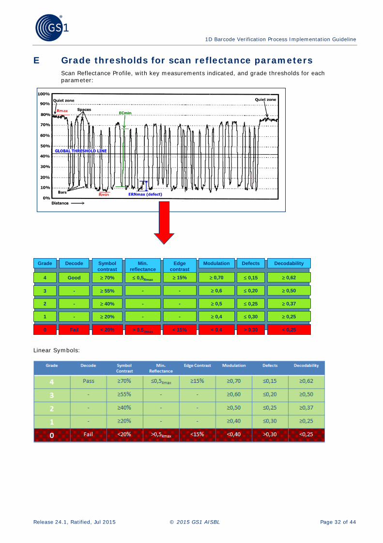
E Grade thresholds for scan reflectance parameters Scan Reflectance Profile, with key measurements indicated, and grade thresholds for each parameter:
Linear Symbols:
Grade
4
3
2
1
0
Decodability
≥ 0,62
≥ 0,50
≥ 0,37
≥ 0,25
< 0,25
Defects
≤ 0,15
≤ 0,20
≤ 0,25
≤ 0,30
> 0,30
Modulation
≥ 0,70
≥ 0,6
≥ 0,5
≥ 0,4
< 0,4
Edge contrast
≥ 15%
-
-
-
< 15%
Min. reflectance
≤ 0,5Rmax
-
-
-
> 0,5Rmax
Symbol contrast
≥ 70%
≥ 55%
≥ 40%
≥ 20%
< 20%
Decode
Good
-
-
-
Fail
Grade
4
3
2
1
0
Decodability
≥ 0,62
≥ 0,50
≥ 0,37
≥ 0,25
< 0,25
Defects
≤ 0,15
≤ 0,20
≤ 0,25
≤ 0,30
> 0,30
Modulation
≥ 0,70
≥ 0,6
≥ 0,5
≥ 0,4
< 0,4
Edge contrast
≥ 15%
-
-
-
< 15%
Min. reflectance
≤ 0,5Rmax
-
-
-
> 0,5Rmax
Symbol contrast
≥ 70%
≥ 55%
≥ 40%
≥ 20%
< 20%
Decode
Good
-
-
-
Fail

1D Barcode Verification Process Implementation Guideline
Release 24.1, Ratified, Jul 2015 © 2015 GS1 AISBL Page 33 of 44
F Use of Calibrated Conformance Standard Test Card (CCSTC) The Calibrated Conformance Standard Test Cards are produced to an extremely high degree of accuracy.
The Calibrated Conformance Standard Test Cards assist in determining if an ISO/IEC 15426-1 based barcode verifier is operating within the manufacturer’s published operating tolerances. Additionally, the Calibrated Conformance Standard Test Card can also function as a guide or training tool in the proper operation of the verifier to assure that the verifier/user combination is providing accurate and repeatable verification results as published by the manufacturers.
Procedures For “Calibrated Conformance Standard Test Card” Use:
The following tests should be performed on a regular basis. The frequency of this testing should adhere to your standard internal quality procedures for quality control equipment calibration / correlation testing. If such procedures do not exist, contact the manufacturer of your verifier for its recommendation. At the minimum, these procedures should be performed any time there is a concern for the operating condition of your verifier or the results gathered by a particular operator, at a minimum every six months.
Follow the manufacturer’s recommended procedure for set up, programming, normal operational calibration and use of the verifier prior to performing any tests.
It is important to note that improper use of the verifier through incorrect set up and/or calibration can cause misleading results. Do not use a calibration card that is old, discoloured or scratched. It is imperative that the operator follows the manufacturer’s procedures for calibration of the verifier. Calibration at a frequency greater than recommended may assure higher accuracy and repeatability.
Care should be taken in the selection of the location where verification is performed. The operator should be aware of unusual ambient light conditions that may affect readings, such as uneven lighting. Additionally, the above mentioned calibration of the device should be performed under the same ambient lighting conditions as those where the testing will be performed.
Operator proficiency can influence the results. Operators must be trained in consistent operation and care should be taken in all testing situations. Barcode verification should be approached the same as any other quality control or quality monitoring function. Practise using the manufacturer’s procedure to obtain the proper combination of control, technique and verifier/operator “interface”. The goal is to obtain consistency of technique when verifying the barcode.
At least ten individual scans of the CCSTC should be taken and the results for each parameter noted. The ten scan grades for each parameter should then be added and averaged. The ten (10) scan average value for each of the quality parameters under test should match the recorded value on the Test Card taking into account the verifier manufacturer’s published specifications and tolerances.
If the test results agree with the recorded value on the card, within the tolerance range of the manufacturer, then the verifier/user combination is considered acceptable and operating properly. If the results do not yield the correct value (again, taking into account the manufacturer’s published tolerances), then the test should be repeated. If, after repeating the test, the results still do not fall within the manufacturer’s stated tolerances then verifier or operator must be considered suspect. If you are assured that the operator’s technique is consistent and controlled and the above test results are still not within the allowable range, you should contact the manufacturer of the equipment for resolution (repair, factory adjustment or recalibration, etc.).

1D Barcode Verification Process Implementation Guideline
Release 24.1, Ratified, Jul 2015 © 2015 GS1 AISBL Page 34 of 44
Figure F-1 : Calibrated Conformance Standard Test Cards
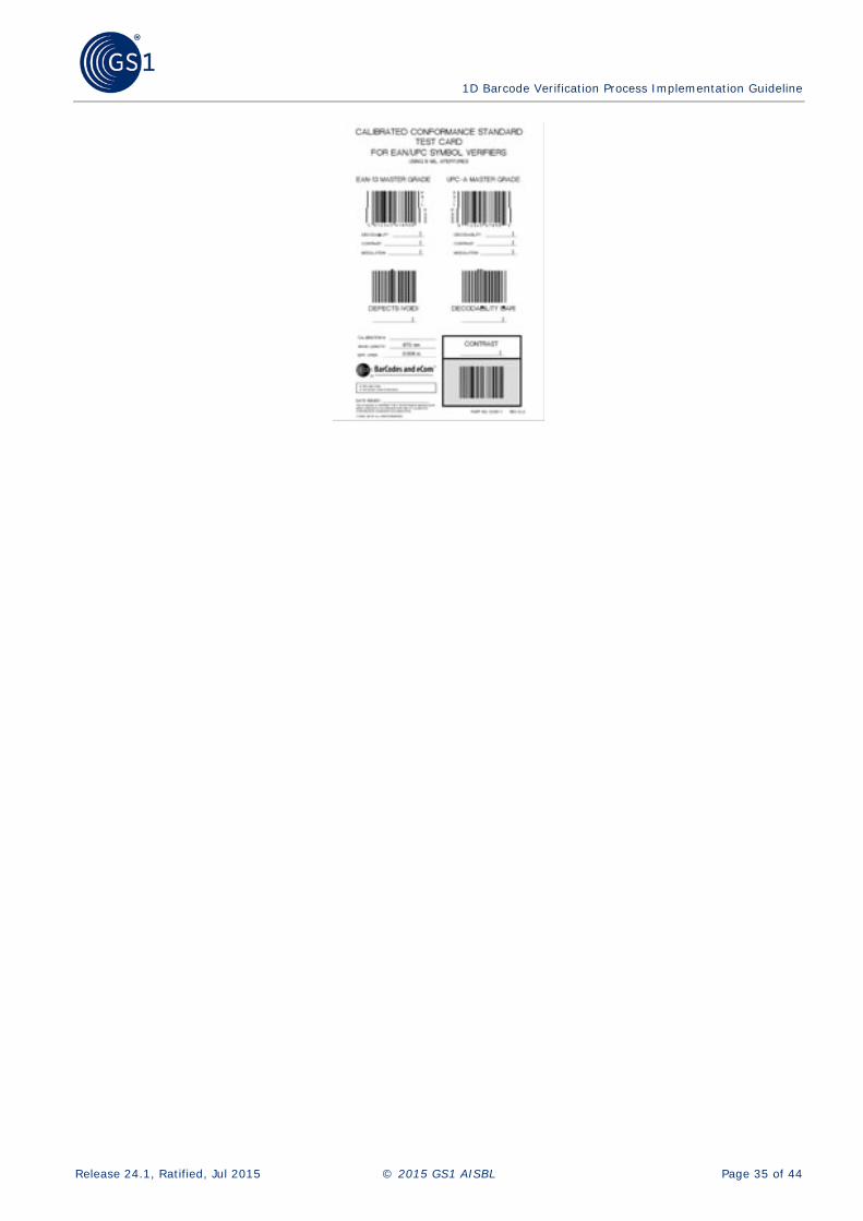
1D Barcode Verification Process Implementation Guideline
Release 24.1, Ratified, Jul 2015 © 2015 GS1 AISBL Page 35 of 44

1D Barcode Verification Process Implementation Guideline
Release 24.1, Ratified, Jul 2015 © 2015 GS1 AISBL Page 36 of 44
G The process of symbol generation 1. Generating the Input Data
■ Symbol generation
■ Developing the Master Film
■ Direct Printing
■ Further Processing, Film Developing (for traditional printing technologies)
■ Film editing
■ Plate developing (Printing plate)
■ Proof printing
■ Printing
■ Quality control after printing
■ Impression (repeated printing) (Steps 4-8, 5-8, 6-8)
Symbols in electronic format (jpg, tiff, pdf, etc.)

1D Barcode Verification Process Implementation Guideline
Release 24.1, Ratified, Jul 2015 © 2015 GS1 AISBL Page 37 of 44
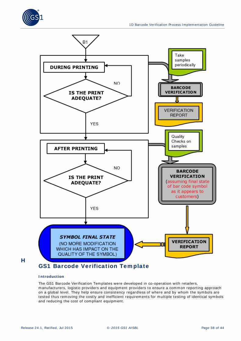
1D Barcode Verification Process Implementation Guideline
Release 24.1, Ratified, Jul 2015 © 2015 GS1 AISBL Page 38 of 44
H GS1 Barcode Verification Template Introduction
The GS1 Barcode Verification Templates were developed in co-operation with retailers, manufacturers, logistic providers and equipment providers to ensure a common reporting approach on a global level. They help ensure consistency regardless of where and by whom the symbols are tested thus removing the costly and inefficient requirements for multiple testing of identical symbols and reducing the cost of compliant equipment.

1D Barcode Verification Process Implementation Guideline
Release 24.1, Ratified, Jul 2015 © 2015 GS1 AISBL Page 39 of 44
These templates do not introduce any requirements in and of themselves. The sole aim is to provide a common reporting format to measure compliance with the numbering and barcoding standards of GS1 laid down elsewhere in the GS1 General Specifications.
The templates are maintained within the GS1 General Specifications. In order to have the latest version of the template, refer to the latest version of the GS1 General Specifications.
Background
GS1 has developed these verification templates on the basis of ISO/IEC 15416 Information technology – Automatic identification and data capture techniques, Barcode Print Quality Test Specifications for Linear Symbols and ISO/IEC 15415 Information technology – Automatic identification and data capture techniques – Barcode print quality test specification – Two dimensional symbols. This not only allows for assessing the quality of printed barcodes but also checks against other key aspects of the GS1 System (symbol location, fit-for purposes, data integrity, etc.).
A GS1 initiated Verifier Conformance Testing Project was conducted because of concerns expressed that different verifiers or verification services were unable to perform consistently. The perception was that different verifiers gave substantially different results when measuring the same symbol. A precisely defined test programme was performed under the auspices of GS1 and concluded that:
■ All verifiers tested (each one ISO compliant) demonstrated the capability of consistent performance.
■ Operators of verifiers require proper training and instruments require regular calibration in accordance with manufacturer recommendations.
■ Most verifiers tested were capable of conforming to GS1 requirements
It is therefore important to stress the need for professional verification services and that barcode print quality should be integral part of an overall quality programme as it provides a quick reference list of symbol quality specifications depending on the symbol type, the application, or the identification number the symbol is carrying.
All GS1 user companies should perform quality control of barcode production and most GS1 Member Organisations offer a verification service. These report templates may be used by any organisation or company as part of a quality programme while respecting the Copyright of the GS1 logo (or any heading or text that imply actual GS1 endorsement (subject to local licensing agreements such as accreditation programmes, which may allow exceptions)).
The templates contained in the GS1 General Specifications highlight critical issues relating to verification and provide a common template for reporting on the most common areas of application. They are not a guarantee of scan performance.

1D Barcode Verification Process Implementation Guideline
Release 24.1, Ratified, Jul 2015 © 2015 GS1 AISBL Page 40 of 44
I Glossary of terms A complete Glossary of terms can be found in the latest version of the GS1 General Specifications. A searchable version of the glossary can be accessed via http://www.gs1.org/glossary
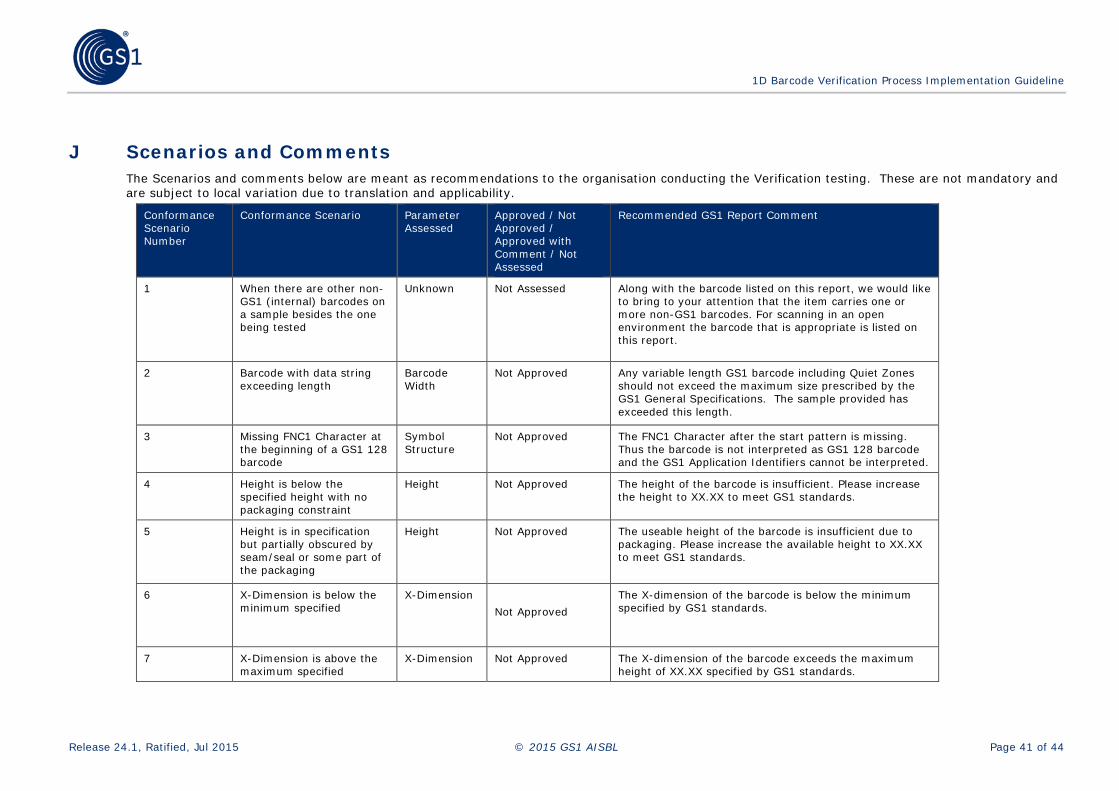
1D Barcode Verification Process Implementation Guideline
Release 24.1, Ratified, Jul 2015 © 2015 GS1 AISBL Page 41 of 44
J Scenarios and Comments The Scenarios and comments below are meant as recommendations to the organisation conducting the Verification testing. These are not mandatory and are subject to local variation due to translation and applicability.
Conformance Scenario Number
Conformance Scenario Parameter Assessed
Approved / Not Approved / Approved with Comment / Not Assessed
Recommended GS1 Report Comment
1 When there are other non-GS1 (internal) barcodes on a sample besides the one being tested
Unknown Not Assessed Along with the barcode listed on this report, we would like to bring to your attention that the item carries one or more non-GS1 barcodes. For scanning in an open environment the barcode that is appropriate is listed on this report.
2 Barcode with data string exceeding length
Barcode Width
Not Approved Any variable length GS1 barcode including Quiet Zones should not exceed the maximum size prescribed by the GS1 General Specifications. The sample provided has exceeded this length.
3 Missing FNC1 Character at the beginning of a GS1 128 barcode
Symbol Structure
Not Approved The FNC1 Character after the start pattern is missing. Thus the barcode is not interpreted as GS1 128 barcode and the GS1 Application Identifiers cannot be interpreted.
4 Height is below the specified height with no packaging constraint
Height Not Approved The height of the barcode is insufficient. Please increase the height to XX.XX to meet GS1 standards.
5 Height is in specification but partially obscured by seam/seal or some part of the packaging
Height Not Approved The useable height of the barcode is insufficient due to packaging. Please increase the available height to XX.XX to meet GS1 standards.
6 X-Dimension is below the minimum specified
X-Dimension Not Approved
The X-dimension of the barcode is below the minimum specified by GS1 standards.
7 X-Dimension is above the maximum specified
X-Dimension Not Approved The X-dimension of the barcode exceeds the maximum height of XX.XX specified by GS1 standards.

1D Barcode Verification Process Implementation Guideline
Release 24.1, Ratified, Jul 2015 © 2015 GS1 AISBL Page 42 of 44
Conformance Scenario Number
Conformance Scenario Parameter Assessed
Approved / Not Approved / Approved with Comment / Not Assessed
Recommended GS1 Report Comment
8 Quiet zone is insufficient Quiet Zone Not Approved The (right/left) Quiet Zone (amount of clear, light, unobstructed area to the left/right of the barcode) is insufficient. Please increase to meet GS1 standards.
9 No Human Readable Interpretation (HRI) associated with barcode
Human Readable Interpretation (HRI)
Not Approved No Human Readable Interpretation (HRI) is printed below the barcode, and this is mandatory
10 Data encoded does not match the human readable interpretation (HRI)
Human Readable Interpretation (HRI)
Not Approved The data printed below the barcode does not match the data encoded in it. Please ensure this is rectified as soon as possible.
11 Barcode cannot be verified Unknown Not Approved The barcode cannot be verified as the print quality is far below what is normally expected, and its origination must be checked'=.
12 Bar Width Ratio (ITF-14) is incorrect (falls outside the acceptable range of 2.25:1 to 3.0:1)
Symbol Structure
Not Approved The bar width ratio (the comparison in width between the wide and narrow bars in the barcode) is out of specification. The target ratio is 2.5:1 (i.e. 2.5 times the width of the narrow segment to one wide segment), but 2.25 to 3.0 is acceptable.
13 Incorrect check digit for GTIN
Data Structure
Not Approved The Check Digit (the last digit) of the GTIN is incorrect and must be recalculated.
14 Incorrect symbol check character (GS1-128)
Symbol Structure
Not Approved The symbol check character (the last but one of the symbol) is incorrect. This is not part of the data being encoded, but it must be correct and present.
15 Incorrect price verifier digit (VMN)
Symbol Structure
Not Approved The price verifier digit is incorrect, correct calculation is essential in order for the barcode to scan.
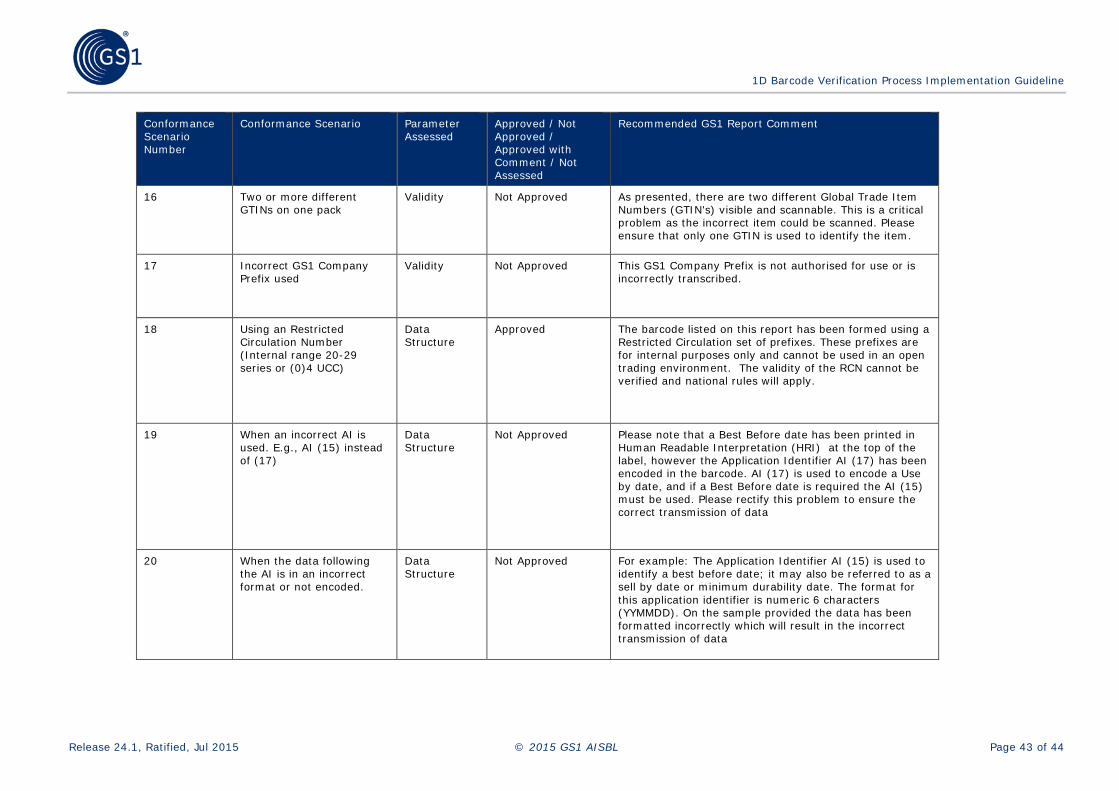
1D Barcode Verification Process Implementation Guideline
Release 24.1, Ratified, Jul 2015 © 2015 GS1 AISBL Page 43 of 44
Conformance Scenario Number
Conformance Scenario Parameter Assessed
Approved / Not Approved / Approved with Comment / Not Assessed
Recommended GS1 Report Comment
16 Two or more different GTINs on one pack
Validity Not Approved As presented, there are two different Global Trade Item Numbers (GTIN's) visible and scannable. This is a critical problem as the incorrect item could be scanned. Please ensure that only one GTIN is used to identify the item.
17
Incorrect GS1 Company Prefix used
Validity Not Approved This GS1 Company Prefix is not authorised for use or is incorrectly transcribed.
18 Using an Restricted Circulation Number (Internal range 20-29 series or (0)4 UCC)
Data Structure
Approved The barcode listed on this report has been formed using a Restricted Circulation set of prefixes. These prefixes are for internal purposes only and cannot be used in an open trading environment. The validity of the RCN cannot be verified and national rules will apply.
19 When an incorrect AI is used. E.g., AI (15) instead of (17)
Data Structure
Not Approved Please note that a Best Before date has been printed in Human Readable Interpretation (HRI) at the top of the label, however the Application Identifier AI (17) has been encoded in the barcode. AI (17) is used to encode a Use by date, and if a Best Before date is required the AI (15) must be used. Please rectify this problem to ensure the correct transmission of data
20 When the data following the AI is in an incorrect format or not encoded.
Data Structure
Not Approved For example: The Application Identifier AI (15) is used to identify a best before date; it may also be referred to as a sell by date or minimum durability date. The format for this application identifier is numeric 6 characters (YYMMDD). On the sample provided the data has been formatted incorrectly which will result in the incorrect transmission of data

1D Barcode Verification Process Implementation Guideline
Release 24.1, Ratified, Jul 2015 © 2015 GS1 AISBL Page 44 of 44
Conformance Scenario Number
Conformance Scenario Parameter Assessed
Approved / Not Approved / Approved with Comment / Not Assessed
Recommended GS1 Report Comment
21 Mandatory association of AIs is not used. Eg AI (02) & (37) without AI (00)
Data Structure
Not Approved For example: The Application Identifier (00) is mandatory when using AI (02) and AI (37).
22 Invalid Pairs of Element Strings are used
Data Structure
Not Approved For example: Application Identifier (02) must not be used for the identification of trade items contained in a trade item identified with Application Identifier (01).
23 Parentheses or Brackets encoded in barcode
Data Structure / Symbol Structure
Not Approved The brackets correctly shown around each AI in the Human Readable Interpretation (HRI) below the barcode have been incorrectly encoded in the symbol itself. These brackets should never be encoded.
24 Additional characters encoded in barcode
Data Structure
Not Approved Application Identifiers (AI) uniquely identify the meaning and format of the data field following. In the sample provided there have been additional, incorrect characters encoded in the data field following the AI. The inclusion of these additional characters will result in the incorrect transmission of data
25 Barcode partially obscured by packaging no ISO grade
Location Not Approved In its current location the barcode is obscured and slightly distorted by the seam/seal of the packaging. In order for the barcode to scan consistently we recommend the barcode be placed on a relatively flat surface clear of any seams or seals.
26 Logistic label: Human Readable Interpretation (HRI) not totally encoded in the symbology
Human Readable Interpretation (HRI)
Not Approved Please ensure that the Human Readable Interpretation located below the barcode is fully represented in the data contained in the barcode.