gsm 05.05 - version 5.0.0 - digital cellular telecommunications
TRANSCRIPT
*
GSM GSM 05.05
TECHNICAL March 1996
SPECIFICATION Version 5.0.0
Source: ETSI TC-SMG Reference: TS/SMG-020505Q
ICS: 33.060.50
Key words: Digital cellular telecommunications system, Global System for Mobile communications (GSM)
Digital cellular telecommunications system (Phase 2+);Radio transmission and reception
(GSM 05.05)
ETSIEuropean Telecommunications Standards Institute
ETSI Secretariat
Postal address: F-06921 Sophia Antipolis CEDEX - FRANCEOffice address: 650 Route des Lucioles - Sophia Antipolis - Valbonne - FRANCEX.400: c=fr, a=atlas, p=etsi, s=secretariat - Internet: [email protected]
Tel.: +33 92 94 42 00 - Fax: +33 93 65 47 16
Copyright Notification: No part may be reproduced except as authorized by written permission. The copyright and theforegoing restriction extend to reproduction in all media.
© European Telecommunications Standards Institute 1996. All rights reserved.
Page 2GSM 05.05 Version 5.0.0: March 1996
Whilst every care has been taken in the preparation and publication of this document, errors in content,typographical or otherwise, may occur. If you have comments concerning its accuracy, please write to"ETSI Editing and Committee Support Dept." at the address shown on the title page.
Page 3GSM 05.05 Version 5.0.0: March 1996
Contents
Foreword .......................................................................................................................................................5
1 Scope ..................................................................................................................................................71.1 Normative references ..........................................................................................................71.2 Abbreviations .......................................................................................................................8
2 Frequency bands and channel arrangement.......................................................................................8
3 Reference configuration ......................................................................................................................9
4 Transmitter characteristics ..................................................................................................................94.1 Output power .......................................................................................................................9
4.1.1 Mobile station ..................................................................................................94.1.2 Base station...................................................................................................10
4.2 Output RF spectrum ..........................................................................................................124.2.1 Spectrum due to the modulation and wide band noise .................................124.2.2 Spectrum due to switching transients............................................................16
4.3 Spurious emissions............................................................................................................174.3.1 Principle of the specification..........................................................................174.3.2 Base transceiver station ................................................................................184.3.3 Mobile station ................................................................................................19
4.4 Radio frequency tolerance .................................................................................................204.5 Output level dynamic operation .........................................................................................20
4.5.1 Base transceiver station ................................................................................204.5.2 Mobile station ................................................................................................20
4.6 Phase accuracy .................................................................................................................204.7 Intermodulation attenuation ...............................................................................................21
4.7.1 Base transceiver station ................................................................................214.7.2 Intra BTS intermodulation attenuation...........................................................214.7.3 Intermodulation between MS (DCS 1800 only) .............................................214.7.4 Mobile PBX (GSM 900 only)..........................................................................21
5 Receiver characteristics ....................................................................................................................225.1 Blocking characteristics .....................................................................................................225.2 AM suppression characteristics .........................................................................................235.3 Intermodulation characteristics ..........................................................................................245.4 Spurious emissions............................................................................................................24
6 Transmitter/receiver performance.....................................................................................................246.1 Nominal error rates (NER) .................................................................................................256.2 Reference sensitivity level .................................................................................................256.3 Reference interference level..............................................................................................256.4 Erroneous frame indication performance ..........................................................................26
Annex A (informative): Spectrum characteristics (spectrum due to the modulation) ..............................31
Annex B (normative): Transmitted power level versus time..................................................................35
Annex C (normative): Propagation conditions .......................................................................................36
C.1 Simple wideband propagation model ................................................................................................36
C.2 Doppler spectrum types ....................................................................................................................36
C.3 Propagation models ..........................................................................................................................37C.3.1 Typical case for rural area (RAx): (6 tap setting) ...............................................................37
Page 4GSM 05.05 Version 5.0.0: March 1996
C.3.2 Typical case for hilly terrain (HTx): (12 tap setting)........................................................... 37C.3.3 Typical case for urban area (TUx): (12 tap setting)........................................................... 38C.3.4 Profile for equalisation test (EQx): (6 tap setting) ............................................................. 38
Annex D (normative): Environmental conditions................................................................................... 39
D.1 General ............................................................................................................................................. 39
D.2 Environmental requirements for the MSs ......................................................................................... 39D.2.1 Temperature...................................................................................................................... 39D.2.2 Voltage .............................................................................................................................. 39D.2.3 Vibration ............................................................................................................................ 40
D.3 Environmental requirements for the BSS equipment ....................................................................... 40
Annex E (normative): Repeater characteristics .................................................................................... 41
E.1 Introduction ....................................................................................................................................... 41
E.2 Spurious emissions .......................................................................................................................... 41
E.3 Intermodulation products .................................................................................................................. 42
E.4 Out of band gain ............................................................................................................................... 42
Annex F (Normative): Antenna Feeder Loss Compensator Characteristics. ........................................ 43
F.1 Introduction ....................................................................................................................................... 43
F.2 Transmitting path.............................................................................................................................. 43F.2.1 Maximum output power..................................................................................................... 43F.2.2 Gain................................................................................................................................... 43F.2.3 Burst transmission characteristics .................................................................................... 44F.2.4 Phase error........................................................................................................................ 44F.2.5 Frequency error................................................................................................................. 44F.2.6 Group delay....................................................................................................................... 45F.2.7 Spurious emissions ........................................................................................................... 45F.2.8 VSWR ............................................................................................................................... 46F.2.9 Stability .............................................................................................................................. 46
F.3 Receiving path .................................................................................................................................. 46F.3.1 Gain................................................................................................................................... 46F.3.2 Noise figure ....................................................................................................................... 46F.3.3 Group delay....................................................................................................................... 46F.3.4 Intermodulation performance ............................................................................................ 46F.3.5 VSWR ............................................................................................................................... 46F.3.6 Stability .............................................................................................................................. 46
F.4 Guidelines (Informative) ................................................................................................................... 46
History ......................................................................................................................................................... 48
Page 5GSM 05.05 Version 5.0.0: March 1996
Foreword
This Global System for Mobile communications Technical Specification (GTS) has been produced by theSpecial Mobile Group (SMG) Technical Committee (TC) of the European Telecommunications StandardsInstitute (ETSI).
This GTS defines the requirements for the transceiver of the pan-european digital mobile cellular andpersonal communication systems operating in the 900 MHz and 1800 MHz band (GSM 900 and DCS1800).
This GTS is a TC-SMG approved GSM technical specification version 5, which contains GSM Phase 2+enhancements/features to the version 4 GSM technical specification. The ETS from which this Phase 2+GTS has evolved is Phase 2 GSM ETS 300 577 edition 6 (GSM 05.05 version 4.14.0).
GTS are produced by TC-SMG to enable the GSM Phase 2+ specifications to become publicly available,prior to submission for the formal ETSI standards approval procedure to become EuropeanTelecommunications Standards (ETS). This ensures the earliest possible access to GSM Phase 2+specifications for all Manufacturers, Network operators and implementors of the Global System for Mobilecommunications.
The contents of this GTS are subject to continuing work within TC-SMG and may change following formalTC-SMG approval. Should TC-SMG modify the contents of this GTS it will then be republished by ETSIwith an identifying change of release date and an increase in version number as follows:
Version 5.x.y
where:y the third digit is incremented when editorial only changes have been incorporated in the
specification;
x the second digit is incremented for all other types of changes, i.e. technical enhancements,corrections, updates, etc.
The specification from which this GTS has been derived was originally based on CEPT documentation,hence the presentation of this GTS may not be entirely in accordance with the ETSI rules.
Reference is made within this GTS to GSM-TSs (note).
NOTE: TC-SMG has produced documents which give the technical specifications for theimplementation of the digital cellular telecommunications system. Historically, thesedocuments have been identified as GSM Technical Specifications (GSM-TSs). TheseTSs may have subsequently become I-ETSs (Phase 1), or ETSs/ETSI TechnicalReports (ETRs) (Phase 2). TC-SMG has also produced ETSI GSM TSs which give thetechnical specifications for the implementation of Phase 2+ enhancements of thedigital cellular telecommunications system. These version 5.x.x GSM TechnicalSpecifications may be referred to as GTSs.

Page 6GSM 05.05 Version 5.0.0: March 1996
Blank page
Page 7GSM 05.05 Version 5.0.0: March 1996
1 Scope
This Global System for Mobile communications Technical Specification (GTS) defines the requirementsfor the transceiver of the pan-european digital mobile cellular and personal communication systemsoperating in the 900 MHz and 1800 MHz band (GSM 900 and DCS 1800).
Requirements are defined for two categories of parameters:
- those that are required to provide compatibility between the radio channels, connected either toseparate or common antennas, that are used in the system. This category also includes parametersproviding compatibility with existing systems in the same or adjacent frequency bands.
- those that define the transmission quality of the system.
This GTS defines RF characteristics for the Mobile Station (MS) and Base Station System (BSS). TheBSS will contain either Base Transceiver Stations (BTS) or microcell base transceiver stations (micro-BTS). The precise measurement methods are specified in GSM 11.10 and 11.20.
Unless otherwise stated, the requirements defined in this GTS apply to the full range of environmentalconditions specified for the equipment (see Annex D).
In this GTS some relaxations are introduced for GSM 900 mobile stations which fulfil the followingconditions:
- pertain to power class 4 or 5 (see section 4.1.1);- have a total weight less than 200 g (excluding battery);- have a volume less than 500 cm3 (excluding battery).
In this standard these mobile stations are referred to as "small MS".
Mobile stations may operate on more than one of the frequency bands specified in section 2. Thesemobile stations, defined in GSM 02.06, are referred to as "Multi band mobile stations" in this standard.Multi band mobile stations shall meet all requirements for each of the bands supported. The relaxation onGSM 900 for a "small MS" are also valid for a multi band MS if it complies with the definition of a smallMS.
The RF characteristics of repeaters are defined in Annex E of this GTS. Annex D and E are the onlysections of this GTS applicable to repeaters. Annex E does not apply to the MS or BSS.
1.1 Normative references
This GTS incorporates by dated and undated reference, provisions from other publications. Thesenormative references are cited at the appropriate places in the text and the publications are listedhereafter. For dated references, subsequent amendments to or revisions of any of these publicationsapply to this GTS only when incorporated in it by amendment or revision. For undated references, thelatest edition of the publication referred to applies.
[1] GSM 01.04 (ETR 100): "Digital cellular telecommunication system (Phase 2);Abbreviations and acronyms".
[2] GSM 02.06 (ETS 300 504): "Digital cellular telecommunication system(Phase 2); Types of Mobile Stations (MS)".
[3] GSM 05.01 (ETS 300 573): "Digital cellular telecommunication system(Phase 2); Physical layer on the radio path General description".
[4] GSM 05.04 (ETS 300 576): "Digital cellular telecommunication system(Phase 2); Modulation".
[5] GSM 05.08 (ETS 300 578): "Digital cellular telecommunication system(Phase 2); Radio subsystem link control".
Page 8GSM 05.05 Version 5.0.0: March 1996
[6] GSM 05.10 (ETS 300 579): "Digital cellular telecommunication system(Phase 2); Radio subsystem synchronisation".
[7] GSM 11.10 (ETS 300 607): "Digital cellular telecommunication system(Phase 2); Mobile Station (MS) conformity specification".
[8] GSM 11.11 (ETS 300 608): "Digital cellular telecommunication system(Phase 2); Specification of the Subscriber Identity Module - Mobile Equipment(SIM - ME) interface".
[9] CCITT Recommendation O.153: "Basic parameters for the measurement oferror performance at bit rates below the primary rate".
[10] ETS 300 019-1-3: "Equipment engineering; Environmental conditions andEnvironmental tests for telecommunications equipment Part 1-3: Classificationof Environmental conditions Stationary use at weather protected locations".
[11] ETS 300 019-1-4: "Equipment engineering; Environmental conditions andEnvironmental tests for telecommunications equipment Part 1-4: Classificationof Environmental conditions Stationary use at non-weather protected locations".
1.2 Abbreviations
Abbreviations used in this GTS are listed in GSM 01.04.
2 Frequency bands and channel arrangement
i) Standard or primary GSM 900 Band, P-GSM;
For Standard GSM 900 Band, the system is required to operate in the following frequency band:
890 - 915 MHz : mobile transmit, base receive935 - 960 MHz : base transmit, mobile receive
ii) Extended GSM 900 Band, E-GSM (includes Standard GSM 900 band):
For Extended GSM 900 band, the system is required to operate in the following frequency band:
880 - 915 MHz : mobile transmit, base receive925 - 960 MHz : base transmit, mobile receive
iii) DCS1800 Band:
For DCS 1800, the system is required to operate in the following band:
1710 - 1785 MHz : mobile transmit, base receive1805 - 1880 MHz : base transmit, mobile receive
NOTE: The term GSM 900 is used for any GSM system which operates in any 900 MHz band.
Operators may implement networks which operates on a combination of the frequency bands above tosupport multi band mobile terminals which are defined in GSM 02.06.
The carrier spacing is 200 kHz.
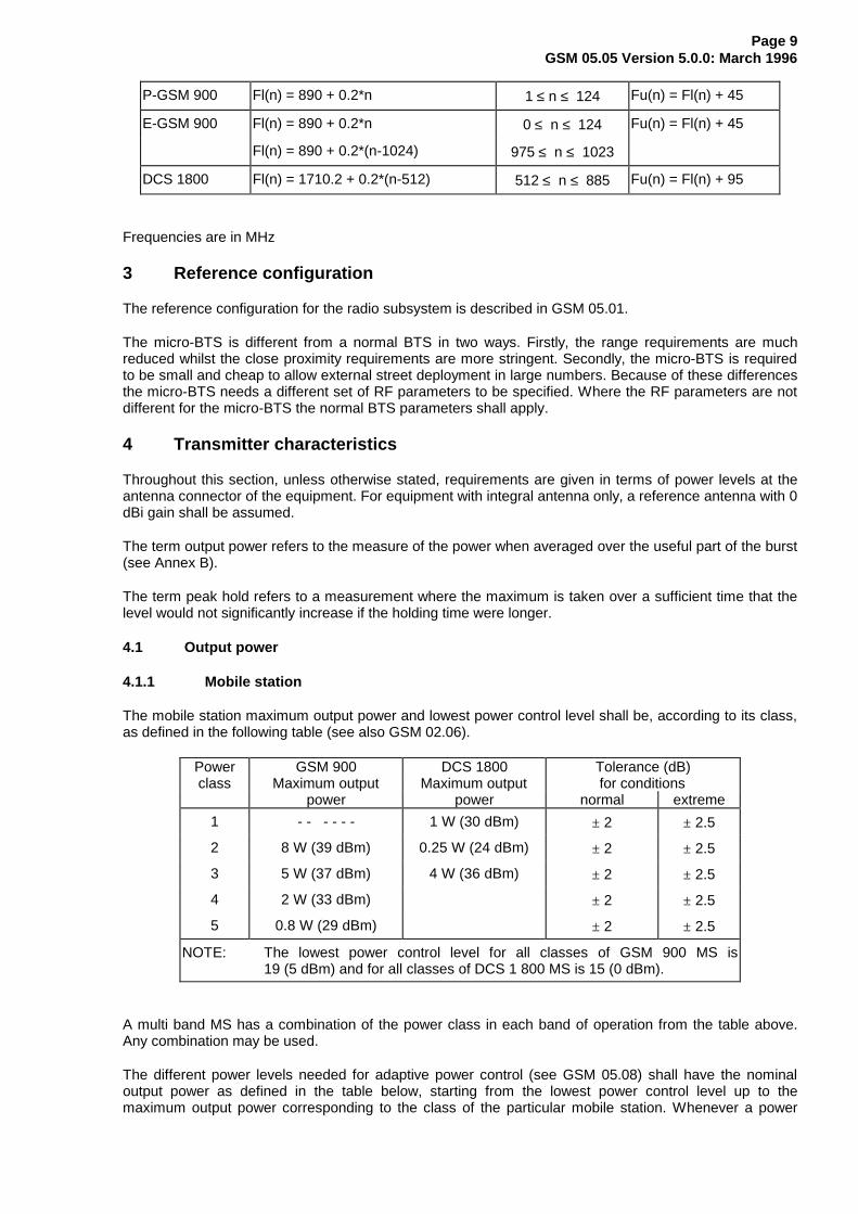
The carrier frequency is designated by the absolute radio frequency channel number (ARFCN). If we callFl(n) the frequency value of the carrier ARFCN n in the lower band, and Fu(n) the correspondingfrequency value in the upper band, we have:
Page 9GSM 05.05 Version 5.0.0: March 1996
P-GSM 900 Fl(n) = 890 + 0.2*n 1 ≤ n ≤ 124 Fu(n) = Fl(n) + 45
E-GSM 900 Fl(n) = 890 + 0.2*n 0 ≤ n ≤ 124 Fu(n) = Fl(n) + 45
Fl(n) = 890 + 0.2*(n-1024) 975 ≤ n ≤ 1023
DCS 1800 Fl(n) = 1710.2 + 0.2*(n-512) 512 ≤ n ≤ 885 Fu(n) = Fl(n) + 95
Frequencies are in MHz
3 Reference configuration
The reference configuration for the radio subsystem is described in GSM 05.01.
The micro-BTS is different from a normal BTS in two ways. Firstly, the range requirements are muchreduced whilst the close proximity requirements are more stringent. Secondly, the micro-BTS is requiredto be small and cheap to allow external street deployment in large numbers. Because of these differencesthe micro-BTS needs a different set of RF parameters to be specified. Where the RF parameters are notdifferent for the micro-BTS the normal BTS parameters shall apply.
4 Transmitter characteristics
Throughout this section, unless otherwise stated, requirements are given in terms of power levels at theantenna connector of the equipment. For equipment with integral antenna only, a reference antenna with 0dBi gain shall be assumed.
The term output power refers to the measure of the power when averaged over the useful part of the burst(see Annex B).
The term peak hold refers to a measurement where the maximum is taken over a sufficient time that thelevel would not significantly increase if the holding time were longer.
4.1 Output power
4.1.1 Mobile station
The mobile station maximum output power and lowest power control level shall be, according to its class,as defined in the following table (see also GSM 02.06).
Power GSM 900 DCS 1800 Tolerance (dB)class Maximum output Maximum output for conditions
power power normal extreme
1 - - - - - - 1 W (30 dBm) ± 2 ± 2.5
2 8 W (39 dBm) 0.25 W (24 dBm) ± 2 ± 2.5
3 5 W (37 dBm) 4 W (36 dBm) ± 2 ± 2.5
4 2 W (33 dBm) ± 2 ± 2.5
5 0.8 W (29 dBm) ± 2 ± 2.5
NOTE: The lowest power control level for all classes of GSM 900 MS is19 (5 dBm) and for all classes of DCS 1 800 MS is 15 (0 dBm).
A multi band MS has a combination of the power class in each band of operation from the table above.Any combination may be used.
The different power levels needed for adaptive power control (see GSM 05.08) shall have the nominaloutput power as defined in the table below, starting from the lowest power control level up to themaximum output power corresponding to the class of the particular mobile station. Whenever a power
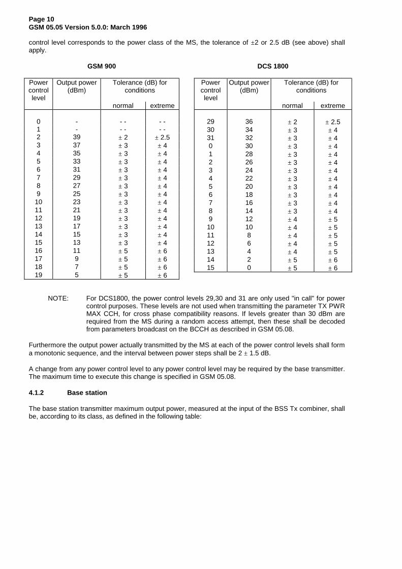
Page 10GSM 05.05 Version 5.0.0: March 1996
control level corresponds to the power class of the MS, the tolerance of ±2 or 2.5 dB (see above) shallapply.
GSM 900
Powercontrollevel
Output power(dBm)
Tolerance (dB) forconditions
normal extreme
0 - - - - -1 - - - - -2 39 ± 2 ± 2.53 37 ± 3 ± 44 35 ± 3 ± 45 33 ± 3 ± 46 31 ± 3 ± 47 29 ± 3 ± 48 27 ± 3 ± 49 25 ± 3 ± 410 23 ± 3 ± 411 21 ± 3 ± 412 19 ± 3 ± 413 17 ± 3 ± 414 15 ± 3 ± 415 13 ± 3 ± 416 11 ± 5 ± 617 9 ± 5 ± 618 7 ± 5 ± 619 5 ± 5 ± 6
DCS 1800
Powercontrollevel
Output power(dBm)
Tolerance (dB) forconditions
normal extreme
29 36 ± 2 ± 2.530 34 ± 3 ± 431 32 ± 3 ± 40 30 ± 3 ± 41 28 ± 3 ± 42 26 ± 3 ± 43 24 ± 3 ± 44 22 ± 3 ± 45 20 ± 3 ± 46 18 ± 3 ± 47 16 ± 3 ± 48 14 ± 3 ± 49 12 ± 4 ± 510 10 ± 4 ± 511 8 ± 4 ± 512 6 ± 4 ± 513 4 ± 4 ± 514 2 ± 5 ± 615 0 ± 5 ± 6
NOTE: For DCS1800, the power control levels 29,30 and 31 are only used "in call" for powercontrol purposes. These levels are not used when transmitting the parameter TX PWRMAX CCH, for cross phase compatibility reasons. If levels greater than 30 dBm arerequired from the MS during a random access attempt, then these shall be decodedfrom parameters broadcast on the BCCH as described in GSM 05.08.
Furthermore the output power actually transmitted by the MS at each of the power control levels shall forma monotonic sequence, and the interval between power steps shall be 2 ± 1.5 dB.
A change from any power control level to any power control level may be required by the base transmitter.The maximum time to execute this change is specified in GSM 05.08.
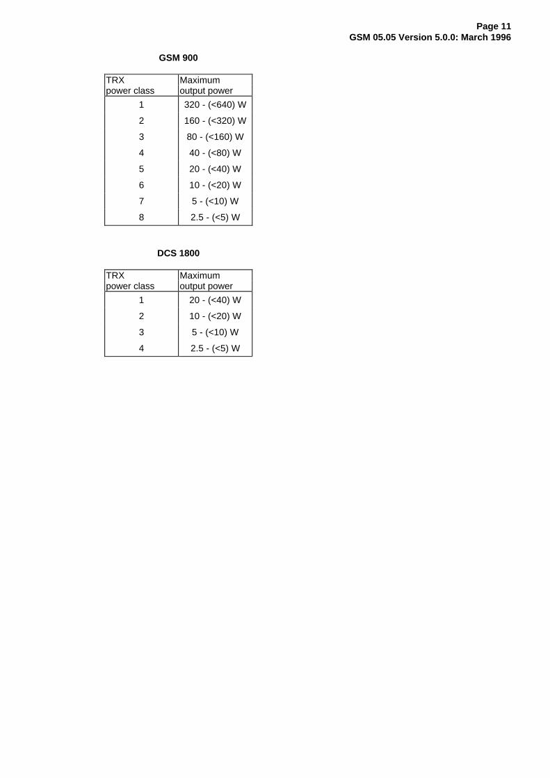
4.1.2 Base station
The base station transmitter maximum output power, measured at the input of the BSS Tx combiner, shallbe, according to its class, as defined in the following table:
Page 11GSM 05.05 Version 5.0.0: March 1996
GSM 900
TRX Maximumpower class output power
1 320 - (<640) W
2 160 - (<320) W
3 80 - (<160) W
4 40 - (<80) W
5 20 - (<40) W
6 10 - (<20) W
7 5 - (<10) W
8 2.5 - (<5) W
DCS 1800
TRX Maximumpower class output power
1 20 - (<40) W
2 10 - (<20) W
3 5 - (<10) W
4 2.5 - (<5) W
Page 12GSM 05.05 Version 5.0.0: March 1996
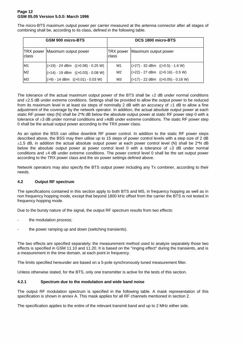
The micro-BTS maximum output power per carrier measured at the antenna connector after all stages ofcombining shall be, according to its class, defined in the following table.
GSM 900 micro-BTS DCS 1800 micro-BTS
TRX powerclass
Maximum output power TRX powerclass
Maximum output power
M1 (>19) - 24 dBm ((>0.08) - 0.25 W) M1 (>27) - 32 dBm ((>0.5) - 1.6 W)
M2 (>14) - 19 dBm ((>0.03) - 0.08 W) M2 (>22) - 27 dBm ((>0.16) - 0.5 W)
M3 (>9) - 14 dBm ((>0.01) - 0.03 W) M3 (>17) - 22 dBm ((>0.05) - 0.16 W)
The tolerance of the actual maximum output power of the BTS shall be ±2 dB under normal conditionsand ±2.5 dB under extreme conditions. Settings shall be provided to allow the output power to be reducedfrom its maximum level in at least six steps of nominally 2 dB with an accuracy of ±1 dB to allow a fineadjustment of the coverage by the network operator. In addition, the actual absolute output power at eachstatic RF power step (N) shall be 2*N dB below the absolute output power at static RF power step 0 with atolerance of ±3 dB under normal conditions and ±4dB under extreme conditions. The static RF power step0 shall be the actual output power according to the TRX power class.
As an option the BSS can utilise downlink RF power control. In addition to the static RF power stepsdescribed above, the BSS may then utilise up to 15 steps of power control levels with a step size of 2 dB±1.5 dB, in addition the actual absolute output power at each power control level (N) shall be 2*N dBbelow the absolute output power at power control level 0 with a tolerance of ±3 dB under normalconditions and ±4 dB under extreme conditions. The power control level 0 shall be the set output poweraccording to the TRX power class and the six power settings defined above.
Network operators may also specify the BTS output power including any Tx combiner, according to theirneeds.
4.2 Output RF spectrum
The specifications contained in this section apply to both BTS and MS, in frequency hopping as well as innon frequency hopping mode, except that beyond 1800 kHz offset from the carrier the BTS is not tested infrequency hopping mode.
Due to the bursty nature of the signal, the output RF spectrum results from two effects:
- the modulation process;
- the power ramping up and down (switching transients).
The two effects are specified separately; the measurement method used to analyze separately those twoeffects is specified in GSM 11.10 and 11.20. It is based on the "ringing effect" during the transients, and isa measurement in the time domain, at each point in frequency.
The limits specified hereunder are based on a 5-pole synchronously tuned measurement filter.
Unless otherwise stated, for the BTS, only one transmitter is active for the tests of this section.
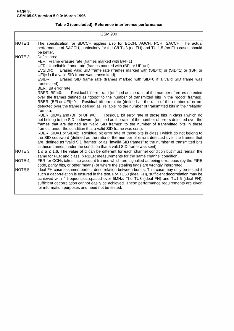
4.2.1 Spectrum due to the modulation and wide band noise
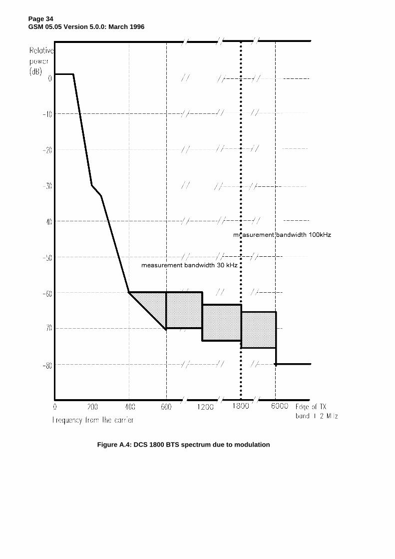
The output RF modulation spectrum is specified in the following table. A mask representation of thisspecification is shown in annex A. This mask applies for all RF channels mentioned in section 2.
The specification applies to the entire of the relevant transmit band and up to 2 MHz either side.
Page 13GSM 05.05 Version 5.0.0: March 1996
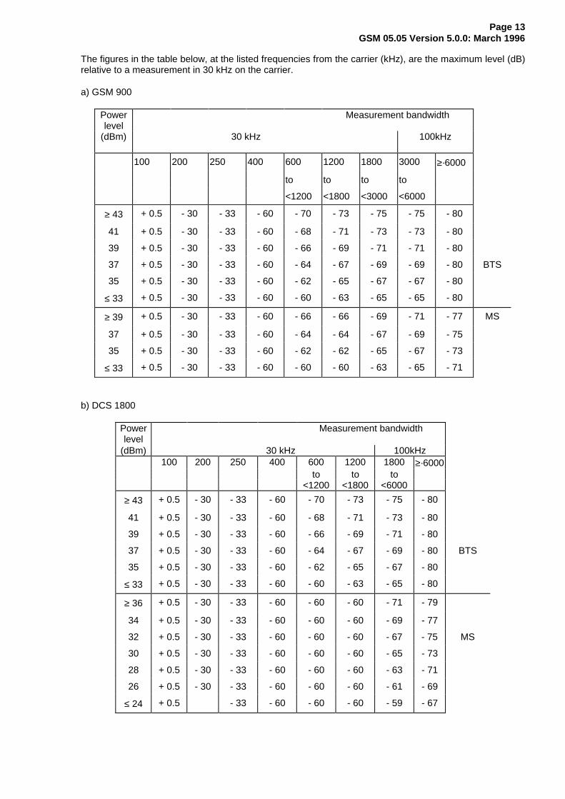
The figures in the table below, at the listed frequencies from the carrier (kHz), are the maximum level (dB)relative to a measurement in 30 kHz on the carrier.
a) GSM 900
Powerlevel
Measurement bandwidth
(dBm) 30 kHz 100kHz
100 200 250 400 600 1200 1800 3000 ≥·6000
to to to to
<1200 <1800 <3000 <6000
≥ 43 + 0.5 - 30 - 33 - 60 - 70 - 73 - 75 - 75 - 80
41 + 0.5 - 30 - 33 - 60 - 68 - 71 - 73 - 73 - 80
39 + 0.5 - 30 - 33 - 60 - 66 - 69 - 71 - 71 - 80
37 + 0.5 - 30 - 33 - 60 - 64 - 67 - 69 - 69 - 80 BTS
35 + 0.5 - 30 - 33 - 60 - 62 - 65 - 67 - 67 - 80
≤ 33 + 0.5 - 30 - 33 - 60 - 60 - 63 - 65 - 65 - 80
≥ 39 + 0.5 - 30 - 33 - 60 - 66 - 66 - 69 - 71 - 77 MS
37 + 0.5 - 30 - 33 - 60 - 64 - 64 - 67 - 69 - 75
35 + 0.5 - 30 - 33 - 60 - 62 - 62 - 65 - 67 - 73
≤ 33 + 0.5 - 30 - 33 - 60 - 60 - 60 - 63 - 65 - 71
b) DCS 1800
Powerlevel
Measurement bandwidth
(dBm) 30 kHz 100kHz100 200 250 400 600 1200 1800 ≥·6000
to to to<1200 <1800 <6000
≥ 43 + 0.5 - 30 - 33 - 60 - 70 - 73 - 75 - 80
41 + 0.5 - 30 - 33 - 60 - 68 - 71 - 73 - 80
39 + 0.5 - 30 - 33 - 60 - 66 - 69 - 71 - 80
37 + 0.5 - 30 - 33 - 60 - 64 - 67 - 69 - 80 BTS
35 + 0.5 - 30 - 33 - 60 - 62 - 65 - 67 - 80
≤ 33 + 0.5 - 30 - 33 - 60 - 60 - 63 - 65 - 80
≥ 36 + 0.5 - 30 - 33 - 60 - 60 - 60 - 71 - 79
34 + 0.5 - 30 - 33 - 60 - 60 - 60 - 69 - 77
32 + 0.5 - 30 - 33 - 60 - 60 - 60 - 67 - 75 MS
30 + 0.5 - 30 - 33 - 60 - 60 - 60 - 65 - 73
28 + 0.5 - 30 - 33 - 60 - 60 - 60 - 63 - 71
26 + 0.5 - 30 - 33 - 60 - 60 - 60 - 61 - 69
≤ 24 + 0.5 - 33 - 60 - 60 - 60 - 59 - 67
Page 14GSM 05.05 Version 5.0.0: March 1996
The specifications assume the following measurement conditions.
For BTS up to 1800 kHz from the carrier and for MS in all cases:
Zero frequency scan, filter bandwidth and video bandwidth of 30 kHz up to 1800 kHz from the carrier and100 kHz beyond 1800 kHz, with averaging done over 50% to 90% of the useful part of the transmittedbursts, excluding the midamble, and then averaged over at least 200 such burst measurements. Above1800 kHz from the carrier only measurements centred on 200 kHz multiples are taken with averaging over50 bursts.
For BTS above 1800 kHz from the carrier swept measurement with:
Filter and video bandwidth of 100 kHz, minimum sweep time of 75 ms, averaging over 200 sweeps. Allslots active, frequency hopping disabled.
When tests are done in frequency hopping mode, the averaging shall include only bursts transmitted whenthe hopping carrier corresponds to the nominal carrier of the measurement. The specifications then applyto the measurement results for any of the hopping frequencies.
The following exceptions and minimum measurement levels shall apply; all absolute levels in dBm shallbe measured using the same bandwidth as that used in the tables a) and b) above:
i) in the combined range 600 kHz to 6 MHz above and below the carrier, in up to three bands of 200kHz width centred on a frequency which is an integer multiple of 200 kHz, exceptions at up to -36dBm are allowed.
ii) above 6 MHz offset from the carrier in up to 12 bands of 200 kHz width centred on a frequencywhich is an integer multiple of 200 kHz, exceptions at up to -36 dBm are allowed. For the BTS onlyone transmitter is active for this test.
iii) for MS measured below 600 kHz from the carrier, if the limit according to the above table is below -36 dBm, a value of -36 dBm shall be used instead. For 600 kHz up to less than 1800 kHz this limitshall be -56 dBm for DCS 1800 MS and -51 dBm for GSM 900 MS. At 1800 kHz and beyond, thislimit shall be -51 dBm for DCS 1800 MS and -46 dBm for GSM 900 MS.
iv) for BTS, if the limit according to the above table is below L, a value L shall be used instead, where Lis L1 dB relative to the output power of the BTS at the lowest static power level measured at 30kHz, or L2 dBm, whichever is higher
For up to 1800 kHz from the carrier: L1 = - 88 dBBeyond 1800 kHz: L1 = - 83 dB
For GSM 900 BTS: L2 = - 65 dBmFor DCS 1800 BTS: L2 = - 57 dBm
The micro-BTS spectrum due to modulation and noise at all frequency offsets greater than 1.8MHz fromcarrier shall be -70 dB for all GSM 900 micro-BTS classes and -76 dB for all DCS 1800 micro-BTSclasses. These are average levels in 100kHz relative to a measurement in 30kHz on carrier. Themeasurement will be made in non-frequency hopping mode under the conditions specified for the normalBTS.
The following exceptions and minimum measurement levels shall apply for the micro-BTS:-
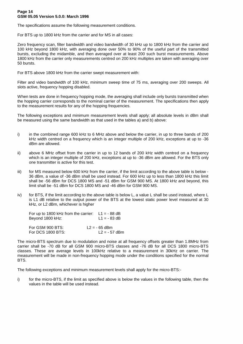
i) for the micro-BTS, if the limit as specified above is below the values in the following table, then thevalues in the table will be used instead.
Page 15GSM 05.05 Version 5.0.0: March 1996
Microcell BTSPower Class
Maximum spectrum due to modulation and noise in 100kHz (dBm)
GSM900 DCS1800
M1 - 59 - 57
M2 - 64 - 62
M3 - 69 - 67
Page 16GSM 05.05 Version 5.0.0: March 1996
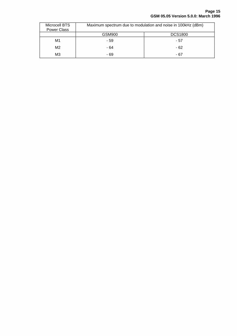
4.2.2 Spectrum due to switching transients
Those effects are also measured in the time domain and the specifications assume the followingmeasurement conditions: zero frequency scan, filter bandwidth 30 kHz, peak hold, and video bandwidth100 kHz.
The example of a waveform due to a burst as seen in a 30 kHz filter offset from the carrier is givenhereunder (figure 1).
Figure 1: Example of a time waveform due to a burst as seen in a 30 kHz filter offset from thecarrier
Page 17GSM 05.05 Version 5.0.0: March 1996
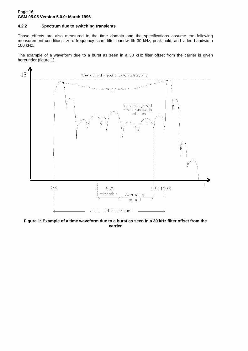
a) Mobile station:
Power level Maximum level measured400 kHz 600 kHz 1200 kHz 1800 kHz
39 dBm - 21 dBm - 26 dBm - 32 dBm - 36 dBm
≤ 37 dBm - 23 dBm - 26 dBm - 32 dBm - 36 dBm
NOTE 1: The relaxations for power level 39 dBm is in line with the modulated spectra and thuscauses negligible additional interference to an analogue system by a GSM signal.
NOTE 2: The near-far dynamics with this specification has been estimated to be approximately58 dB for MS operating at a power level of 8 W or 49 dB for MS operating at a powerlevel of 1 W. The near-far dynamics then gradually decreases by 2 dB per power leveldown to 32 dB for MS operating in cells with a maximum allowed output power of 20mW or 29 dB for MS operating at 10 mW.
NOTE 3: The possible performance degradation due to switching transient leaking into thebeginning or the end of a burst, was estimated and found to be acceptable with respectto the BER due to cochannel interference (C/I).
b) Base transceiver station:
The maximum level measured, after any filters and combiners, at the indicated offset from the carrier, is:
Maximum level measured400 kHz 600 kHz 1200 kHz 1800 kHz
GSM 900 - 57 dBc - 67 dBc - 74 dBc - 74 dBcDCS 1800 - 50 dBc - 58 dBc - 66 dBc - 66 dBc
or -36 dBm, whichever is the higher.
dBc means relative to the output power at the BTS, measured at the same point and in a filter bandwidthof at least 300 kHz.
NOTE: Some of the above requirements are different from those specified in section 4.3.2.
4.3 Spurious emissions
The limits specified hereunder are based on a 5-pole synchronously tuned measurement filter.
4.3.1 Principle of the specification
In this section, the spurious transmissions (whether modulated or unmodulated) and the switchingtransients are specified together by measuring the peak power in a given bandwidth at variousfrequencies. The bandwidth is increased as the frequency offset between the measurement frequencyand, either the carrier, or the edge of the MS or BTS transmit band, increases. The effect for spurioussignals of widening the measurement bandwidth is to reduce the allowed total spurious energy per MHz.The effect for switching transients is to effectively reduce the allowed level of the switching transients (thepeak level of a switching transient increases by 6 dB for each doubling of the measurement bandwidth).The conditions are specified in the following table, a peak-hold measurement being assumed.
The measurement conditions for radiated and conducted spurious are specified separately in GSM 11.10and 11.20. The frequency bands where these are actually measured may differ from one type to the other(see GSM 11.10 and 11.20).
Page 18GSM 05.05 Version 5.0.0: March 1996
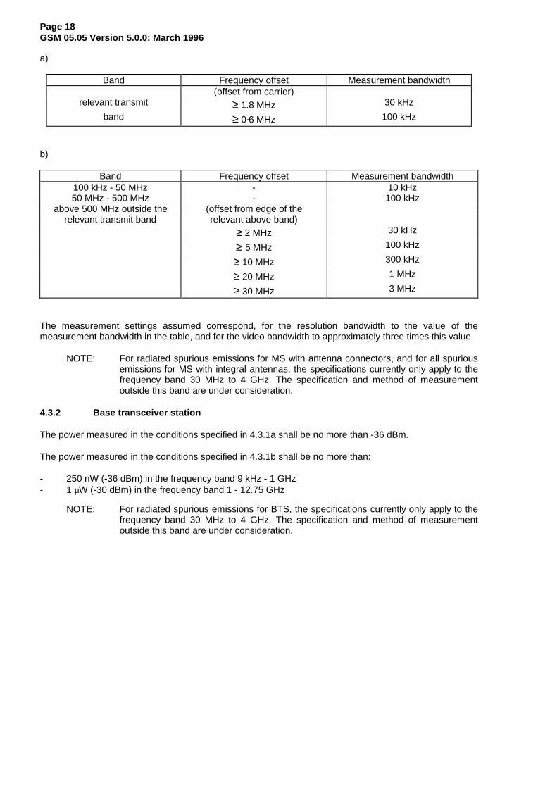
a)
Band Frequency offset Measurement bandwidth(offset from carrier)
relevant transmit ≥ 1.8 MHz 30 kHz
band ≥ 0·6 MHz 100 kHz
b)
Band Frequency offset Measurement bandwidth100 kHz - 50 MHz - 10 kHz50 MHz - 500 MHz - 100 kHz
above 500 MHz outside the (offset from edge of therelevant transmit band relevant above band)
≥ 2 MHz 30 kHz
≥ 5 MHz 100 kHz
≥ 10 MHz 300 kHz
≥ 20 MHz 1 MHz
≥ 30 MHz 3 MHz
The measurement settings assumed correspond, for the resolution bandwidth to the value of themeasurement bandwidth in the table, and for the video bandwidth to approximately three times this value.
NOTE: For radiated spurious emissions for MS with antenna connectors, and for all spuriousemissions for MS with integral antennas, the specifications currently only apply to thefrequency band 30 MHz to 4 GHz. The specification and method of measurementoutside this band are under consideration.
4.3.2 Base transceiver station
The power measured in the conditions specified in 4.3.1a shall be no more than -36 dBm.
The power measured in the conditions specified in 4.3.1b shall be no more than:
- 250 nW (-36 dBm) in the frequency band 9 kHz - 1 GHz- 1 µW (-30 dBm) in the frequency band 1 - 12.75 GHz
NOTE: For radiated spurious emissions for BTS, the specifications currently only apply to thefrequency band 30 MHz to 4 GHz. The specification and method of measurementoutside this band are under consideration.
Page 19GSM 05.05 Version 5.0.0: March 1996
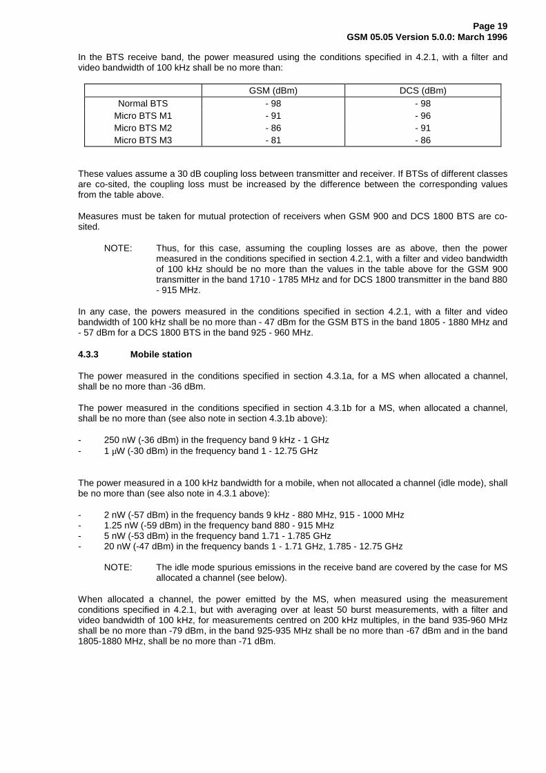
In the BTS receive band, the power measured using the conditions specified in 4.2.1, with a filter andvideo bandwidth of 100 kHz shall be no more than:
GSM (dBm) DCS (dBm)Normal BTS - 98 - 98
Micro BTS M1 - 91 - 96Micro BTS M2 - 86 - 91Micro BTS M3 - 81 - 86
These values assume a 30 dB coupling loss between transmitter and receiver. If BTSs of different classesare co-sited, the coupling loss must be increased by the difference between the corresponding valuesfrom the table above.
Measures must be taken for mutual protection of receivers when GSM 900 and DCS 1800 BTS are co-sited.
NOTE: Thus, for this case, assuming the coupling losses are as above, then the powermeasured in the conditions specified in section 4.2.1, with a filter and video bandwidthof 100 kHz should be no more than the values in the table above for the GSM 900transmitter in the band 1710 - 1785 MHz and for DCS 1800 transmitter in the band 880- 915 MHz.
In any case, the powers measured in the conditions specified in section 4.2.1, with a filter and videobandwidth of 100 kHz shall be no more than - 47 dBm for the GSM BTS in the band 1805 - 1880 MHz and- 57 dBm for a DCS 1800 BTS in the band 925 - 960 MHz.
4.3.3 Mobile station
The power measured in the conditions specified in section 4.3.1a, for a MS when allocated a channel,shall be no more than -36 dBm.
The power measured in the conditions specified in section 4.3.1b for a MS, when allocated a channel,shall be no more than (see also note in section 4.3.1b above):
- 250 nW (-36 dBm) in the frequency band 9 kHz - 1 GHz- 1 µW (-30 dBm) in the frequency band 1 - 12.75 GHz
The power measured in a 100 kHz bandwidth for a mobile, when not allocated a channel (idle mode), shallbe no more than (see also note in 4.3.1 above):
- 2 nW (-57 dBm) in the frequency bands 9 kHz - 880 MHz, 915 - 1000 MHz- 1.25 nW (-59 dBm) in the frequency band 880 - 915 MHz- 5 nW (-53 dBm) in the frequency band 1.71 - 1.785 GHz- 20 nW (-47 dBm) in the frequency bands 1 - 1.71 GHz, 1.785 - 12.75 GHz
NOTE: The idle mode spurious emissions in the receive band are covered by the case for MSallocated a channel (see below).
When allocated a channel, the power emitted by the MS, when measured using the measurementconditions specified in 4.2.1, but with averaging over at least 50 burst measurements, with a filter andvideo bandwidth of 100 kHz, for measurements centred on 200 kHz multiples, in the band 935-960 MHzshall be no more than -79 dBm, in the band 925-935 MHz shall be no more than -67 dBm and in the band1805-1880 MHz, shall be no more than -71 dBm.
Page 20GSM 05.05 Version 5.0.0: March 1996
As exceptions up to five measurements with a level up to -36 dBm are permitted in each of the bands925-960 MHz and 1805-1880 MHz for each ARFCN used in the measurements.
When hopping, this applies to each set of measurements, grouped by the hopping frequencies asdescribed in section 4.2.1.
4.4 Radio frequency tolerance
The radio frequency tolerance for the base transceiver station and the mobile station is defined in GSM05.10.
4.5 Output level dynamic operation
NOTE: The term "any transmit band channel" is used here to mean:any RF channel of 200 kHz bandwidth centred on a multiple of 200 kHz which is withinthe relevant transmit band.
4.5.1 Base transceiver station
The BTS shall be capable of not transmitting a burst in a time slot not used by a logical channel or whereDTX applies. The output power relative to time when sending a burst is shown in annex B. In the casewhere the bursts in two (or several) consecutive time slots are actually transmitted, at the samefrequency, no requirements are specified to the power ramping in the guard times between the active timeslots, and the template of annex B shall be respected at the beginning and the end of the series ofconsecutive bursts. The residual output power, if a timeslot is not activated, shall be maintained at, orbelow, a level of -30 dBc on the frequency channel in use. All emissions related to other frequencychannels shall be in accordance with the wide band noise and spurious emissions requirements.
A measurement bandwidth of at least 300 kHz is assumed.
4.5.2 Mobile station
The output power can be reduced by steps of 2 dB as listed in section 4.1.
The transmitted power level relative to time when sending a burst is shown in Annex B. The timing of thetransmitted burst is specified in GSM 05.10. Between the active bursts, the residual output power shall bemaintained at, or below, the level of:
- -59 dBc or -54 dBm, whichever is the greater for GSM 900, except for the time slot preceding theactive slot, for which this value is equal to -36 dBm;
- -48 dBc or -48 dBm, whichever is the greater for DCS 1800;
in any transmit band channel.
A measurement bandwidth of at least 300 kHz is assumed.
The transmitter, when in idle mode, will respect the conditions of section 4.3.3.
4.6 Phase accuracy
When transmitting a burst, the phase accuracy of the signal, relative to the theoretical modulatedwaveforms as specified in GSM 05.04, is specified in the following way.
For any 148-bits subsequence of the 511-bits pseudo-random sequence, defined in CCITTRecommendation O.153 fascicle IV.4, the phase error trajectory on the useful part of the burst (includingtail bits), shall be measured by computing the difference between the phase of the transmitted waveformand the phase of the expected one. The RMS phase error (difference between the phase error trajectoryand its linear regression on the active part of the time slot) shall not be greater than 5° with a maximumpeak deviation during the useful part of the burst less than 20°.
Page 21GSM 05.05 Version 5.0.0: March 1996
NOTE: Using the encryption (ciphering mode) is an allowed means to generate the pseudo-random sequence.
The burst timing of the modulated carrier in the active part of the time slot shall be chosen to ensure thatall the modulating bits in the useful part of the burst (see GSM 05.04) influence the output phase in a timeslot.
4.7 Intermodulation attenuation
The intermodulation attenuation is the ratio of the power level of the wanted signal to the power level of anintermodulation component. It is a measure of the capability of the transmitter to inhibit the generation ofsignals in its non-linear elements caused by the presence of the carrier and an interfering signal reachingthe transmitter via the antenna.
4.7.1 Base transceiver station
An interfering CW signal shall be applied within the relevant BTS TX band at a frequency offset of ≥ 800kHz, and with a power level 30 dB below the power level of the wanted signal.
The intermodulation products shall meet the requirements in 4.7.2
4.7.2 Intra BTS intermodulation attenuation
In a BTS intermodulation may be caused by combining several RF channels to feed a single antenna, orwhen operating them in the close vicinity of each other. The BTS shall be configured with each transmitteroperating at the maximum allowed power, with a full complement of transceivers and with modulationapplied. For the measurement in the transmit band the equipment shall be operated at equal andminimum carrier frequency spacing specified for the BSS configuration under test. For the measurementin the receive band the equipment shall be operated with such a channel configuration that at least 3rdorder intermodulation products fall into the receive band.
All the following requirements relate to frequency offsets from the uppermost and lowermost carriers. Thepeak hold value of intermodulation components over a timeslot, shall not exceed -70 dBc or -36 dBm,whichever is the higher, for frequency offsets between 6 MHz and the edge of the relevant Tx bandmeasured in a 300 kHz bandwidth. 1 in 100 timeslots may fail this test by up to a level of 10 dB. Foroffsets between 600 kHz to 6 MHz the requirements and the measurement technique is that specified inSection 4.2.1.
The other requirements of section 4.3.2 in the band 9 kHz to 12.75 GHz shall still be met.
4.7.3 Intermodulation between MS (DCS 1800 only)
The maximum level of any intermodulation product, when measured as peak hold in a 300 kHz bandwidth,shall be 50 dB below the wanted signal when an interfering CW signal is applied within the DCS 1800 MStransmit band at a frequency offset of 800 kHz with a power level 40 dB below the power level of thewanted (DCS 1800 modulated) signal.
4.7.4 Mobile PBX (GSM 900 only)
In a mobile PBX intermodulation may be caused when operating transmitters in the close vicinity of eachother. The intermodulation specification for mobile PBXs (GSM 900 only) shall be that stated in section4.7.2.
Page 22GSM 05.05 Version 5.0.0: March 1996
5 Receiver characteristics
In this section, the requirements are given in terms of power levels at the antenna connector of thereceiver. Equipment with integral antenna may be taken into account by converting these power levelrequirements into field strength requirements, assuming a 0 dBi gain antenna. This means that the testson equipment on integral antenna will consider fields strengths (E) related to the power levels (P)specified, by the following formula (derived from the formula E = P + 20logF(MHz) + 77.2):
assuming F = 925 MHz : E (dBµV/m) = P (dBm) + 136.5 for GSM 900assuming F = 1795 MHz : E (dBµV/m) = P (dBm) + 142.3 for DCS 1800
Static propagation conditions are assumed in all cases, for both wanted and unwanted signals. Forsections 5.1 and 5.2, values given in dBm are indicative, and calculated assuming a 50 ohms impedance.
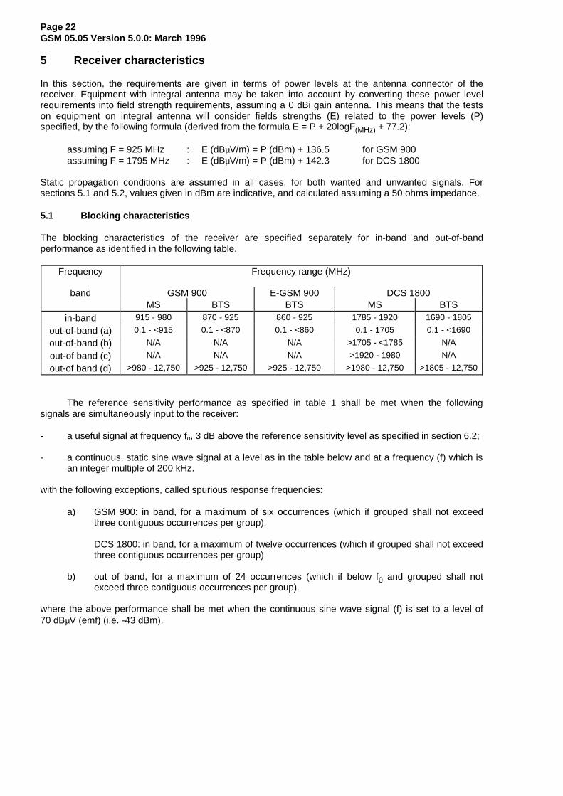
5.1 Blocking characteristics
The blocking characteristics of the receiver are specified separately for in-band and out-of-bandperformance as identified in the following table.
Frequency Frequency range (MHz)
band GSM 900 E-GSM 900 DCS 1800MS BTS BTS MS BTS
in-band 915 - 980 870 - 925 860 - 925 1785 - 1920 1690 - 1805
out-of-band (a) 0.1 - <915 0.1 - <870 0.1 - <860 0.1 - 1705 0.1 - <1690
out-of-band (b) N/A N/A N/A >1705 - <1785 N/A
out-of band (c) N/A N/A N/A >1920 - 1980 N/A
out-of band (d) >980 - 12,750 >925 - 12,750 >925 - 12,750 >1980 - 12,750 >1805 - 12,750
The reference sensitivity performance as specified in table 1 shall be met when the followingsignals are simultaneously input to the receiver:
- a useful signal at frequency fo, 3 dB above the reference sensitivity level as specified in section 6.2;
- a continuous, static sine wave signal at a level as in the table below and at a frequency (f) which isan integer multiple of 200 kHz.
with the following exceptions, called spurious response frequencies:
a) GSM 900: in band, for a maximum of six occurrences (which if grouped shall not exceedthree contiguous occurrences per group),
DCS 1800: in band, for a maximum of twelve occurrences (which if grouped shall not exceedthree contiguous occurrences per group)
b) out of band, for a maximum of 24 occurrences (which if below f0 and grouped shall notexceed three contiguous occurrences per group).
where the above performance shall be met when the continuous sine wave signal (f) is set to a level of70 dBµV (emf) (i.e. -43 dBm).
Page 23GSM 05.05 Version 5.0.0: March 1996
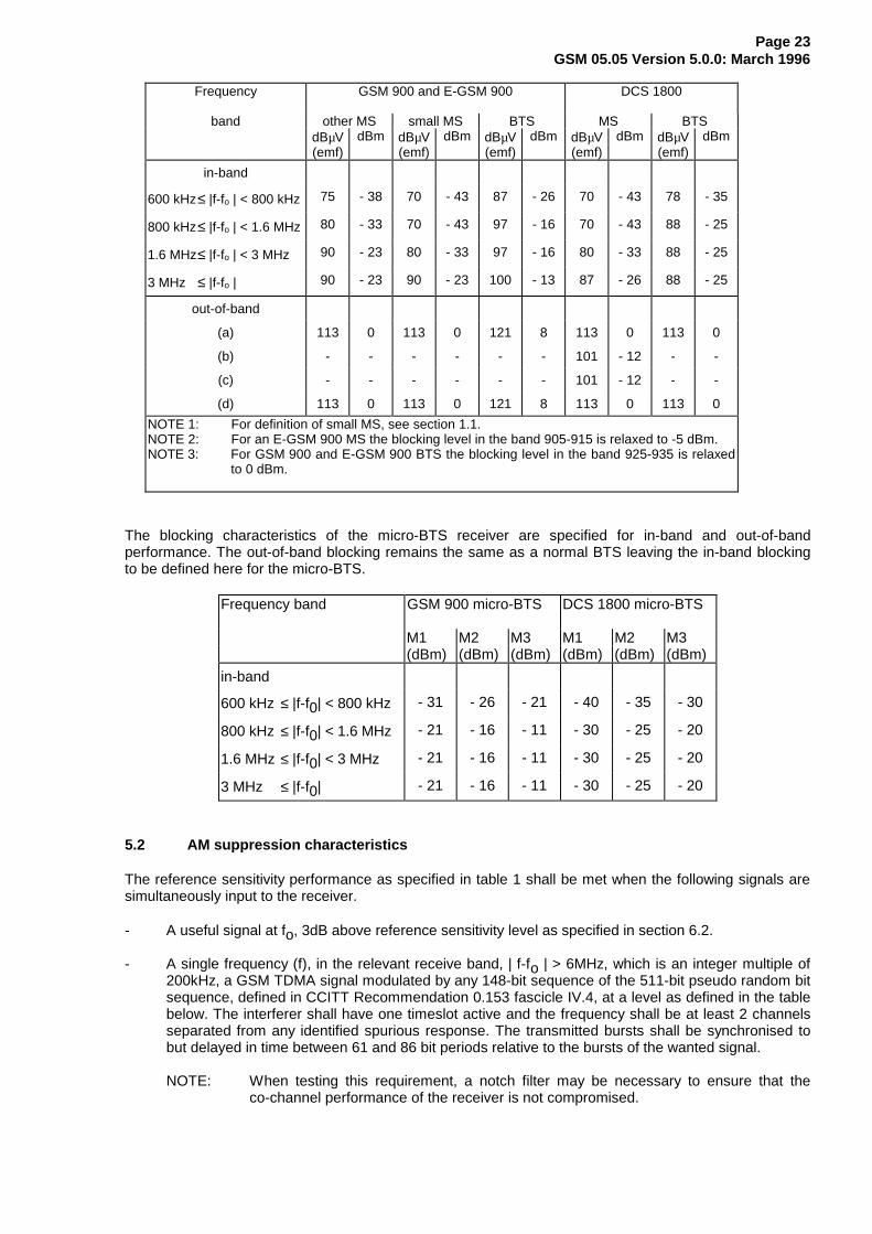
Frequency GSM 900 and E-GSM 900 DCS 1800
band other MS small MS BTS MS BTSdBµV dBm dBµV dBm dBµV dBm dBµV dBm dBµV dBm(emf) (emf) (emf) (emf) (emf)
in-band
600 kHz≤ |f-fo | < 800 kHz 75 - 38 70 - 43 87 - 26 70 - 43 78 - 35
800 kHz≤ |f-fo | < 1.6 MHz 80 - 33 70 - 43 97 - 16 70 - 43 88 - 25
1.6 MHz≤ |f-fo | < 3 MHz 90 - 23 80 - 33 97 - 16 80 - 33 88 - 25
3 MHz ≤ |f-fo | 90 - 23 90 - 23 100 - 13 87 - 26 88 - 25
out-of-band
(a) 113 0 113 0 121 8 113 0 113 0
(b) - - - - - - 101 - 12 - -
(c) - - - - - - 101 - 12 - -
(d) 113 0 113 0 121 8 113 0 113 0
NOTE 1: For definition of small MS, see section 1.1.NOTE 2: For an E-GSM 900 MS the blocking level in the band 905-915 is relaxed to -5 dBm.NOTE 3: For GSM 900 and E-GSM 900 BTS the blocking level in the band 925-935 is relaxed
to 0 dBm.
The blocking characteristics of the micro-BTS receiver are specified for in-band and out-of-bandperformance. The out-of-band blocking remains the same as a normal BTS leaving the in-band blockingto be defined here for the micro-BTS.
Frequency band GSM 900 micro-BTS DCS 1800 micro-BTS
M1 M2 M3 M1 M2 M3(dBm) (dBm) (dBm) (dBm) (dBm) (dBm)
in-band
600 kHz ≤ |f-f0| < 800 kHz - 31 - 26 - 21 - 40 - 35 - 30
800 kHz ≤ |f-f0| < 1.6 MHz - 21 - 16 - 11 - 30 - 25 - 20
1.6 MHz ≤ |f-f0| < 3 MHz - 21 - 16 - 11 - 30 - 25 - 20
3 MHz ≤ |f-f0| - 21 - 16 - 11 - 30 - 25 - 20
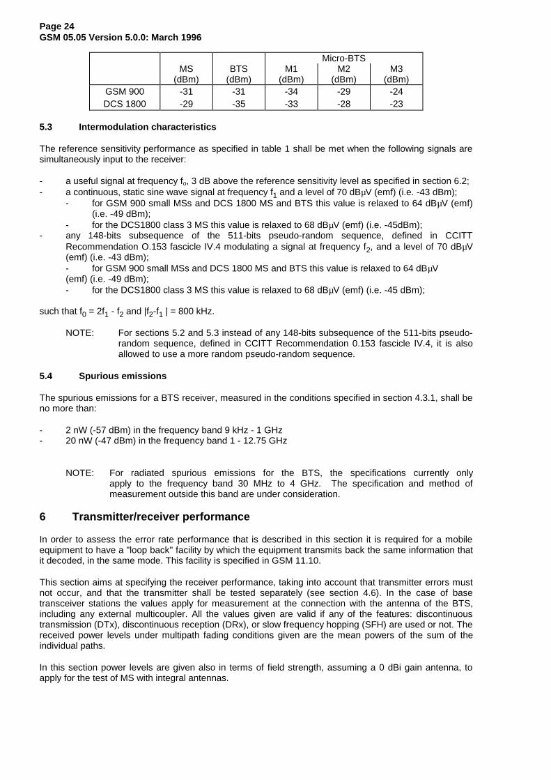
5.2 AM suppression characteristics
The reference sensitivity performance as specified in table 1 shall be met when the following signals aresimultaneously input to the receiver.
- A useful signal at fo, 3dB above reference sensitivity level as specified in section 6.2.
- A single frequency (f), in the relevant receive band, | f-fo | > 6MHz, which is an integer multiple of200kHz, a GSM TDMA signal modulated by any 148-bit sequence of the 511-bit pseudo random bitsequence, defined in CCITT Recommendation 0.153 fascicle IV.4, at a level as defined in the tablebelow. The interferer shall have one timeslot active and the frequency shall be at least 2 channelsseparated from any identified spurious response. The transmitted bursts shall be synchronised tobut delayed in time between 61 and 86 bit periods relative to the bursts of the wanted signal.
NOTE: When testing this requirement, a notch filter may be necessary to ensure that theco-channel performance of the receiver is not compromised.
Page 24GSM 05.05 Version 5.0.0: March 1996
Micro-BTSMS BTS M1 M2 M3
(dBm) (dBm) (dBm) (dBm) (dBm)GSM 900 -31 -31 -34 -29 -24DCS 1800 -29 -35 -33 -28 -23
5.3 Intermodulation characteristics
The reference sensitivity performance as specified in table 1 shall be met when the following signals aresimultaneously input to the receiver:
- a useful signal at frequency fo, 3 dB above the reference sensitivity level as specified in section 6.2;- a continuous, static sine wave signal at frequency f1 and a level of 70 dBµV (emf) (i.e. -43 dBm);
- for GSM 900 small MSs and DCS 1800 MS and BTS this value is relaxed to 64 dBµV (emf)(i.e. -49 dBm);
- for the DCS1800 class 3 MS this value is relaxed to 68 dBµV (emf) (i.e. -45dBm);- any 148-bits subsequence of the 511-bits pseudo-random sequence, defined in CCITT
Recommendation O.153 fascicle IV.4 modulating a signal at frequency f2, and a level of 70 dBµV(emf) (i.e. -43 dBm);- for GSM 900 small MSs and DCS 1800 MS and BTS this value is relaxed to 64 dBµV(emf) (i.e. -49 dBm);- for the DCS1800 class 3 MS this value is relaxed to 68 dBµV (emf) (i.e. -45 dBm);
such that f0 = 2f1 - f2 and |f2-f1 | = 800 kHz.
NOTE: For sections 5.2 and 5.3 instead of any 148-bits subsequence of the 511-bits pseudo-random sequence, defined in CCITT Recommendation 0.153 fascicle IV.4, it is alsoallowed to use a more random pseudo-random sequence.
5.4 Spurious emissions
The spurious emissions for a BTS receiver, measured in the conditions specified in section 4.3.1, shall beno more than:
- 2 nW (-57 dBm) in the frequency band 9 kHz - 1 GHz- 20 nW (-47 dBm) in the frequency band 1 - 12.75 GHz
NOTE: For radiated spurious emissions for the BTS, the specifications currently onlyapply to the frequency band 30 MHz to 4 GHz. The specification and method ofmeasurement outside this band are under consideration.
6 Transmitter/receiver performance
In order to assess the error rate performance that is described in this section it is required for a mobileequipment to have a "loop back" facility by which the equipment transmits back the same information thatit decoded, in the same mode. This facility is specified in GSM 11.10.
This section aims at specifying the receiver performance, taking into account that transmitter errors mustnot occur, and that the transmitter shall be tested separately (see section 4.6). In the case of basetransceiver stations the values apply for measurement at the connection with the antenna of the BTS,including any external multicoupler. All the values given are valid if any of the features: discontinuoustransmission (DTx), discontinuous reception (DRx), or slow frequency hopping (SFH) are used or not. Thereceived power levels under multipath fading conditions given are the mean powers of the sum of theindividual paths.
In this section power levels are given also in terms of field strength, assuming a 0 dBi gain antenna, toapply for the test of MS with integral antennas.
Page 25GSM 05.05 Version 5.0.0: March 1996
6.1 Nominal error rates (NER)
This section describes the transmission requirements in terms of error rates in nominal conditions i.e.without interference and with an input level of 20 dB above the reference sensitivity level. The relevantpropagation conditions appear in Annex C.
Under the following propagation conditions, the chip error rate, equivalent to the bit error rate of the nonprotected bits (TCH/FS, class II) shall have the following limits:
- static channel: BER ≤ 10-4
- EQ50 channel: BER ≤ 3 %
This performance shall be maintained up to -40 dBm input level for static and multipath conditions.Furthermore, for static conditions, a bit error rate of 10-3 shall be maintained up to -15 dBm for GSM 900,-23 dBm for DCS 1800.
6.2 Reference sensitivity level
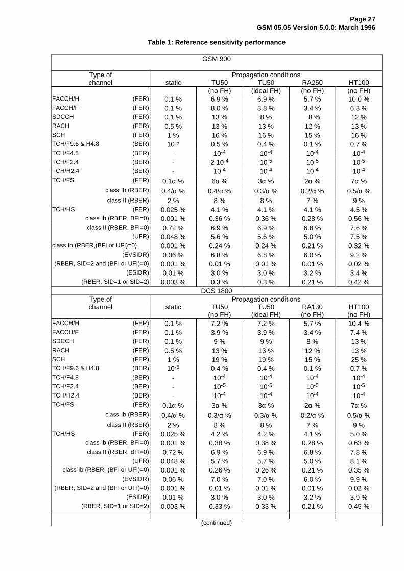
The reference sensitivity performance in terms of frame erasure, bit error, or residual bit error rates(whichever appropriate) is specified in table 1, according to the type of channel and the propagationcondition. The actual sensitivity level is defined as the input level for which this performance is met. Theactual sensitivity level shall be less than a specified limit, called the reference sensitivity level. Thereference sensitivity level shall be:
- for DCS 1800 class 1 or class 2 MS : -100 dBm- for DCS 1800 class 3 MS : -102 dBm- for GSM 900 small MS : -102 dBm- for other GSM 900 MS and normal BTS : -104 dBm- for GSM 900 micro BTS M1 : -97 dBm- for GSM 900 micro BTS M2 : -92 dBm- for GSM 900 micro BTS M3 : -87 dBm- for DCS 1800 micro BTS M1 : -102 dBm- for DCS 1800 micro BTS M2 : -97 dBm- for DCS 1800 micro BTS M3 : -92 dBm
The above specifications for BTS shall be met when the two adjacent timeslots to the wanted aredetecting valid GSM signals at 50 dB above the power on the wanted timeslot. For MS the abovespecifications shall be met with the two adjacent timeslots 20 dB above the own timeslot and the staticchannel.
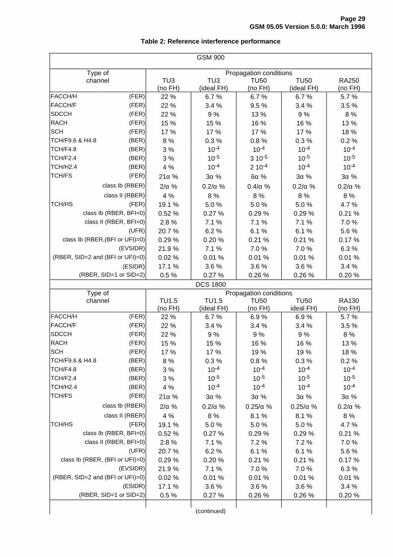
6.3 Reference interference level
The reference interference performance (for cochannel, C/Ic, or adjacent channel, C/Ia) in terms of frameerasure, bit error or residual bit error rates (whichever appropriate) is specified in table 2, according to thetype of channel and the propagation condition. The actual interference ratio is defined as the interferenceratio for which this performance is met. The actual interference ratio shall be less than a specified limit,called the reference interference ratio. The reference interference ratio shall be, for BTS and all types ofMS:
- for cochannel interference : C/Ic = 9 dB- for adjacent (200 kHz) interference : C/Ia1 = - 9 dB- for adjacent (400 kHz) interference : C/Ia2 = - 41 dB- for adjacent (600 kHz) interference : C/Ia3 = - 49 dB
NOTE: The C/Ia3 figure is given for information purposes and will not require testing. It wascalculated for the case of an equipment with an antenna connector, operating at outputpower levels of +33 dBm and below. Rejection of signals at 600 kHz is specified insection 5.1.
These specifications apply for a wanted signal input level of 20 dB above the reference sensitivity level,and for a random, continuous, GSM-modulated interfering signal. In case of frequency hopping, the
Page 26GSM 05.05 Version 5.0.0: March 1996
interference and the wanted signals shall have the same frequency hopping sequence. In any case thewanted and interfering signals shall be subject to the same propagation profiles (see Annex C),independent on the two channels.
For a GSM 900 MS and a DCS 1800 MS the reference interference performance according to table 2 forco-channel interference (C/Ic) shall be maintained for RA250/130 propagation conditions if the time ofarrival of the wanted signal is periodically alternated by steps of 8µs in either direction. The period shall be32 seconds (16 seconds with the early and 16 seconds with the late time of arrival alternately).
For adjacent channel interference propagation conditions other than TU50 need not be tested. If, in orderto ease measurement, a TU50 (no FH) faded wanted signal, and a static adjacent channel interferer areused, the reference interference performance shall be:
GSM 900 DCS 1800TCH/FS (FER): 10.2α% 5.1α%
Class Ib (RBER): 0.72/α% 0.45/α%Class II (RBER): 8.8% 8.9%
FACCH (FER): 17.1% 6.1%
6.4 Erroneous frame indication performance
a) On a speech TCH (TCH/FS or TCH/HS) or a SDCCH with a random RF input, of the framesbelieved to be FACCH, SACCH, or SDCCH frames, the overall reception performance shall besuch that no more than 0.002% of the frames are assessed to be error free.
b) On a speech TCH (TCH/FS or TCH/HS) with a random RF input, the overall reception performanceshall be such that, on average, less than one undetected bad speech frame (false bad frameindication BFI) shall be measured in one minute for MS. The requirement for BTS is for furtherstudy.
c) On a speech TCH (TCH/FS or TCH/HS), when DTX is activated with frequency hopping through C0where bursts comprising SID frames, SACCH frames and Dummy bursts are received at a level20dB above the reference sensitivity level and with no transmission at the other bursts of the TCH,the overall reception performance shall be such that, on average less than one undetected badspeech frame (false bad frame indication BFI) shall be measured in one minute for MS. Therequirement for BTS is for further study.
d) For a BTS on a RACH with a random RF input, the overall reception performance shall be such thatless than 0.02 % of frames are assessed to be error free.
Page 27GSM 05.05 Version 5.0.0: March 1996
Table 1: Reference sensitivity performance
GSM 900
Type of Propagation conditionschannel static TU50 TU50 RA250 HT100
(no FH) (ideal FH) (no FH) (no FH)FACCH/H (FER) 0.1 % 6.9 % 6.9 % 5.7 % 10.0 %FACCH/F (FER) 0.1 % 8.0 % 3.8 % 3.4 % 6.3 %SDCCH (FER) 0.1 % 13 % 8 % 8 % 12 %RACH (FER) 0.5 % 13 % 13 % 12 % 13 %SCH (FER) 1 % 16 % 16 % 15 % 16 %TCH/F9.6 & H4.8 (BER) 10-5 0.5 % 0.4 % 0.1 % 0.7 %TCH/F4.8 (BER) - 10-4 10-4 10-4 10-4
TCH/F2.4 (BER) - 2 10-4 10-5 10-5 10-5
TCH/H2.4 (BER) - 10-4 10-4 10-4 10-4
TCH/FS (FER) 0.1α % 6α % 3α % 2α % 7α %class Ib (RBER) 0.4/α % 0.4/α % 0.3/α % 0.2/α % 0.5/α %class II (RBER) 2 % 8 % 8 % 7 % 9 %
TCH/HS (FER) 0.025 % 4.1 % 4.1 % 4.1 % 4.5 %class Ib (RBER, BFI=0) 0.001 % 0.36 % 0.36 % 0.28 % 0.56 %class II (RBER, BFI=0) 0.72 % 6.9 % 6.9 % 6.8 % 7.6 %
(UFR) 0.048 % 5.6 % 5.6 % 5.0 % 7.5 %class Ib (RBER,(BFI or UFI)=0) 0.001 % 0.24 % 0.24 % 0.21 % 0.32 %
(EVSIDR) 0.06 % 6.8 % 6.8 % 6.0 % 9.2 %(RBER, SID=2 and (BFI or UFI)=0) 0.001 % 0.01 % 0.01 % 0.01 % 0.02 %
(ESIDR) 0.01 % 3.0 % 3.0 % 3.2 % 3.4 %(RBER, SID=1 or SID=2) 0.003 % 0.3 % 0.3 % 0.21 % 0.42 %
DCS 1800Type of Propagation conditionschannel static TU50
(no FH)TU50
(ideal FH)RA130(no FH)
HT100(no FH)
FACCH/H (FER) 0.1 % 7.2 % 7.2 % 5.7 % 10.4 %FACCH/F (FER) 0.1 % 3.9 % 3.9 % 3.4 % 7.4 %SDCCH (FER) 0.1 % 9 % 9 % 8 % 13 %RACH (FER) 0.5 % 13 % 13 % 12 % 13 %SCH (FER) 1 % 19 % 19 % 15 % 25 %TCH/F9.6 & H4.8 (BER) 10-5 0.4 % 0.4 % 0.1 % 0.7 %TCH/F4.8 (BER) - 10-4 10-4 10-4 10-4
TCH/F2.4 (BER) - 10-5 10-5 10-5 10-5
TCH/H2.4 (BER) - 10-4 10-4 10-4 10-4
TCH/FS (FER) 0.1α % 3α % 3α % 2α % 7α %class Ib (RBER) 0.4/α % 0.3/α % 0.3/α % 0.2/α % 0.5/α %class II (RBER) 2 % 8 % 8 % 7 % 9 %
TCH/HS (FER) 0.025 % 4.2 % 4.2 % 4.1 % 5.0 %class Ib (RBER, BFI=0) 0.001 % 0.38 % 0.38 % 0.28 % 0.63 %class II (RBER, BFI=0) 0.72 % 6.9 % 6.9 % 6.8 % 7.8 %
(UFR) 0.048 % 5.7 % 5.7 % 5.0 % 8.1 %class Ib (RBER, (BFI or UFI)=0) 0.001 % 0.26 % 0.26 % 0.21 % 0.35 %
(EVSIDR) 0.06 % 7.0 % 7.0 % 6.0 % 9.9 %(RBER, SID=2 and (BFI or UFI)=0) 0.001 % 0.01 % 0.01 % 0.01 % 0.02 %
(ESIDR) 0.01 % 3.0 % 3.0 % 3.2 % 3.9 %(RBER, SID=1 or SID=2) 0.003 % 0.33 % 0.33 % 0.21 % 0.45 %
(continued)
Page 28GSM 05.05 Version 5.0.0: March 1996
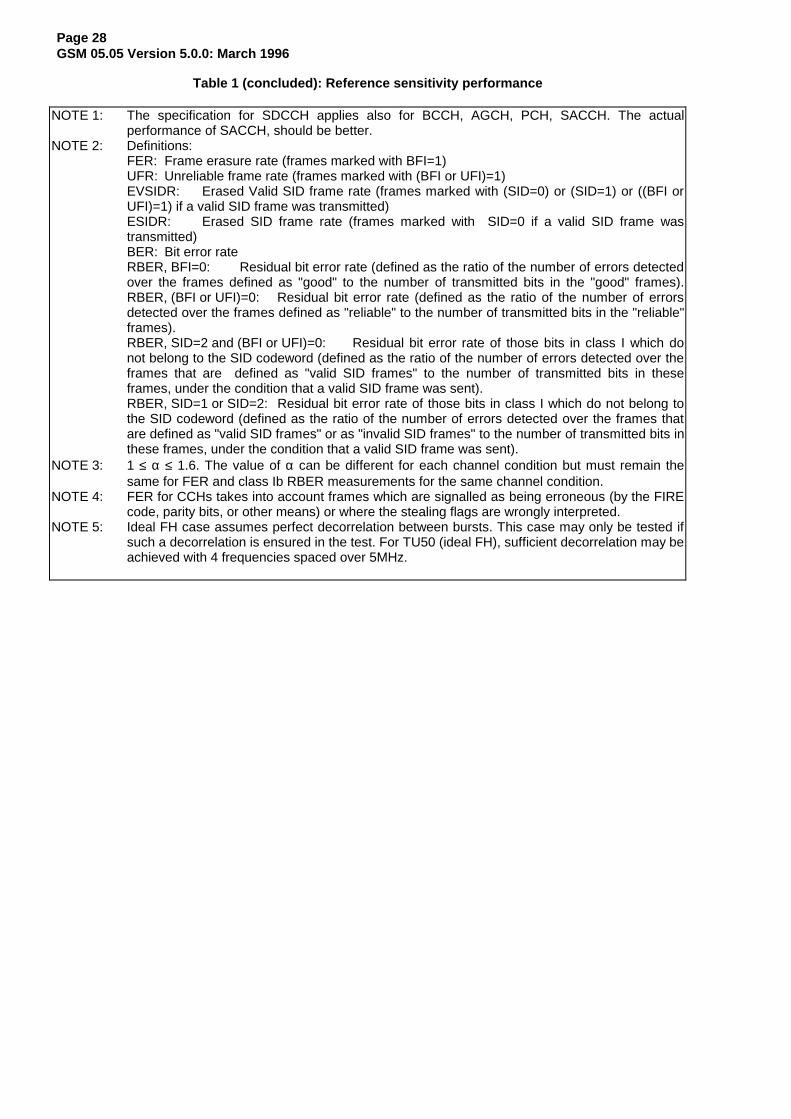
Table 1 (concluded): Reference sensitivity performance
NOTE 1: The specification for SDCCH applies also for BCCH, AGCH, PCH, SACCH. The actualperformance of SACCH, should be better.
NOTE 2: Definitions:FER: Frame erasure rate (frames marked with BFI=1)UFR: Unreliable frame rate (frames marked with (BFI or UFI)=1)EVSIDR: Erased Valid SID frame rate (frames marked with (SID=0) or (SID=1) or ((BFI orUFI)=1) if a valid SID frame was transmitted)ESIDR: Erased SID frame rate (frames marked with SID=0 if a valid SID frame wastransmitted)BER: Bit error rateRBER, BFI=0: Residual bit error rate (defined as the ratio of the number of errors detectedover the frames defined as "good" to the number of transmitted bits in the "good" frames).RBER, (BFI or UFI)=0: Residual bit error rate (defined as the ratio of the number of errorsdetected over the frames defined as "reliable" to the number of transmitted bits in the "reliable"frames).RBER, SID=2 and (BFI or UFI)=0: Residual bit error rate of those bits in class I which donot belong to the SID codeword (defined as the ratio of the number of errors detected over theframes that are defined as "valid SID frames" to the number of transmitted bits in theseframes, under the condition that a valid SID frame was sent).RBER, SID=1 or SID=2: Residual bit error rate of those bits in class I which do not belong tothe SID codeword (defined as the ratio of the number of errors detected over the frames thatare defined as "valid SID frames" or as "invalid SID frames" to the number of transmitted bits inthese frames, under the condition that a valid SID frame was sent).
NOTE 3: 1 ≤ α ≤ 1.6. The value of α can be different for each channel condition but must remain thesame for FER and class Ib RBER measurements for the same channel condition.
NOTE 4: FER for CCHs takes into account frames which are signalled as being erroneous (by the FIREcode, parity bits, or other means) or where the stealing flags are wrongly interpreted.
NOTE 5: Ideal FH case assumes perfect decorrelation between bursts. This case may only be tested ifsuch a decorrelation is ensured in the test. For TU50 (ideal FH), sufficient decorrelation may beachieved with 4 frequencies spaced over 5MHz.
Page 29GSM 05.05 Version 5.0.0: March 1996
Table 2: Reference interference performance
GSM 900
Type of Propagation conditionschannel TU3
(no FH)TU3
(ideal FH)TU50
(no FH)TU50
(ideal FH)RA250(no FH)
FACCH/H (FER) 22 % 6.7 % 6.7 % 6.7 % 5.7 %FACCH/F (FER) 22 % 3.4 % 9.5 % 3.4 % 3.5 %SDCCH (FER) 22 % 9 % 13 % 9 % 8 %RACH (FER) 15 % 15 % 16 % 16 % 13 %SCH (FER) 17 % 17 % 17 % 17 % 18 %TCH/F9.6 & H4.8 (BER) 8 % 0.3 % 0.8 % 0.3 % 0.2 %TCH/F4.8 (BER) 3 % 10-4 10-4 10-4 10-4
TCH/F2.4 (BER) 3 % 10-5 3 10-5 10-5 10-5
TCH/H2.4 (BER) 4 % 10-4 2 10-4 10-4 10-4
TCH/FS (FER) 21α % 3α % 6α % 3α % 3α %class Ib (RBER) 2/α % 0.2/α % 0.4/α % 0.2/α % 0.2/α %class II (RBER) 4 % 8 % 8 % 8 % 8 %
TCH/HS (FER) 19.1 % 5.0 % 5.0 % 5.0 % 4.7 %class Ib (RBER, BFI=0) 0.52 % 0.27 % 0.29 % 0.29 % 0.21 %class II (RBER, BFI=0) 2.8 % 7.1 % 7.1 % 7.1 % 7.0 %
(UFR) 20.7 % 6.2 % 6.1 % 6.1 % 5.6 %class Ib (RBER,(BFI or UFI)=0) 0.29 % 0.20 % 0.21 % 0.21 % 0.17 %
(EVSIDR) 21.9 % 7.1 % 7.0 % 7.0 % 6.3 %(RBER, SID=2 and (BFI or UFI)=0) 0.02 % 0.01 % 0.01 % 0.01 % 0.01 %
(ESIDR) 17.1 % 3.6 % 3.6 % 3.6 % 3.4 %(RBER, SID=1 or SID=2) 0.5 % 0.27 % 0.26 % 0.26 % 0.20 %
DCS 1800Type of Propagation conditionschannel TU1.5
(no FH)TU1.5
(ideal FH)TU50
(no FH)TU50
ideal FH)RA130(no FH)
FACCH/H (FER) 22 % 6.7 % 6.9 % 6.9 % 5.7 %FACCH/F (FER) 22 % 3.4 % 3.4 % 3.4 % 3.5 %SDCCH (FER) 22 % 9 % 9 % 9 % 8 %RACH (FER) 15 % 15 % 16 % 16 % 13 %SCH (FER) 17 % 17 % 19 % 19 % 18 %TCH/F9.6 & H4.8 (BER) 8 % 0.3 % 0.8 % 0.3 % 0.2 %TCH/F4.8 (BER) 3 % 10-4 10-4 10-4 10-4
TCH/F2.4 (BER) 3 % 10-5 10-5 10-5 10-5
TCH/H2.4 (BER) 4 % 10-4 10-4 10-4 10-4
TCH/FS (FER) 21α % 3α % 3α % 3α % 3α %class Ib (RBER) 2/α % 0.2/α % 0.25/α % 0.25/α % 0.2/α %class II (RBER) 4 % 8 % 8.1 % 8.1 % 8 %
TCH/HS (FER) 19.1 % 5.0 % 5.0 % 5.0 % 4.7 %class Ib (RBER, BFI=0) 0.52 % 0.27 % 0.29 % 0.29 % 0.21 %class II (RBER, BFI=0) 2.8 % 7.1 % 7.2 % 7.2 % 7.0 %
(UFR) 20.7 % 6.2 % 6.1 % 6.1 % 5.6 %class Ib (RBER, (BFI or UFI)=0) 0.29 % 0.20 % 0.21 % 0.21 % 0.17 %
(EVSIDR) 21.9 % 7.1 % 7.0 % 7.0 % 6.3 %(RBER, SID=2 and (BFI or UFI)=0) 0.02 % 0.01 % 0.01 % 0.01 % 0.01 %
(ESIDR) 17.1 % 3.6 % 3.6 % 3.6 % 3.4 %(RBER, SID=1 or SID=2) 0.5 % 0.27 % 0.26 % 0.26 % 0.20 %
(continued)
Page 30GSM 05.05 Version 5.0.0: March 1996
Table 2 (concluded): Reference interference performance
GSM 900
NOTE 1: The specification for SDCCH applies also for BCCH, AGCH, PCH, SACCH. The actualperformance of SACCH, particularly for the C/I TU3 (no FH) and TU 1.5 (no FH) cases shouldbe better.
NOTE 2: Definitions:FER: Frame erasure rate (frames marked with BFI=1)UFR: Unreliable frame rate (frames marked with (BFI or UFI)=1)EVSIDR: Erased Valid SID frame rate (frames marked with (SID=0) or (SID=1) or ((BFI orUFI)=1) if a valid SID frame was transmitted)ESIDR: Erased SID frame rate (frames marked with SID=0 if a valid SID frame wastransmitted)BER: Bit error rateRBER, BFI=0: Residual bit error rate (defined as the ratio of the number of errors detectedover the frames defined as "good" to the number of transmitted bits in the "good" frames).RBER, (BFI or UFI)=0: Residual bit error rate (defined as the ratio of the number of errorsdetected over the frames defined as "reliable" to the number of transmitted bits in the "reliable"frames).RBER, SID=2 and (BFI or UFI)=0: Residual bit error rate of those bits in class I which donot belong to the SID codeword (defined as the ratio of the number of errors detected over theframes that are defined as "valid SID frames" to the number of transmitted bits in theseframes, under the condition that a valid SID frame was sent).RBER, SID=1 or SID=2: Residual bit error rate of those bits in class I which do not belong tothe SID codeword (defined as the ratio of the number of errors detected over the frames thatare defined as "valid SID frames" or as "invalid SID frames" to the number of transmitted bitsin these frames, under the condition that a valid SID frame was sent).
NOTE 3: 1 ≤ α ≤ 1.6. The value of α can be different for each channel condition but must remain thesame for FER and class Ib RBER measurements for the same channel condition.
NOTE 4: FER for CCHs takes into account frames which are signalled as being erroneous (by the FIREcode, parity bits, or other means) or where the stealing flags are wrongly interpreted.
NOTE 5: Ideal FH case assumes perfect decorrelation between bursts. This case may only be tested ifsuch a decorrelation is ensured in the test. For TU50 (ideal FH), sufficient decorrelation may beachieved with 4 frequencies spaced over 5MHz. The TU3 (ideal FH) and TU1.5 (ideal FH),sufficient decorrelation cannot easily be achieved. These performance requirements are givenfor information purposes and need not be tested.
Page 31GSM 05.05 Version 5.0.0: March 1996
Annex A (informative): Spectrum characteristics (spectrum due to themodulation)
Figure A.1: GSM 900 MS spectrum due to modulation
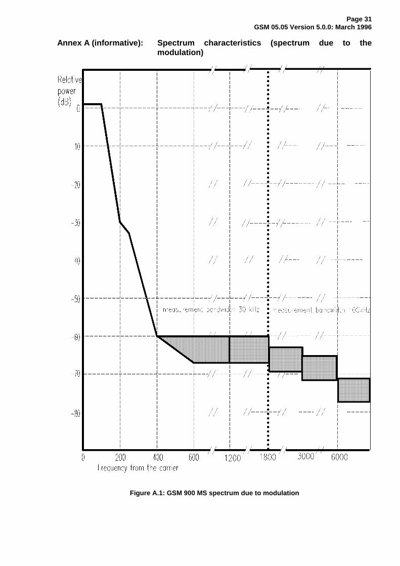
Page 32GSM 05.05 Version 5.0.0: March 1996
Figure A.2: GSM 900 BTS spectrum due to modulation
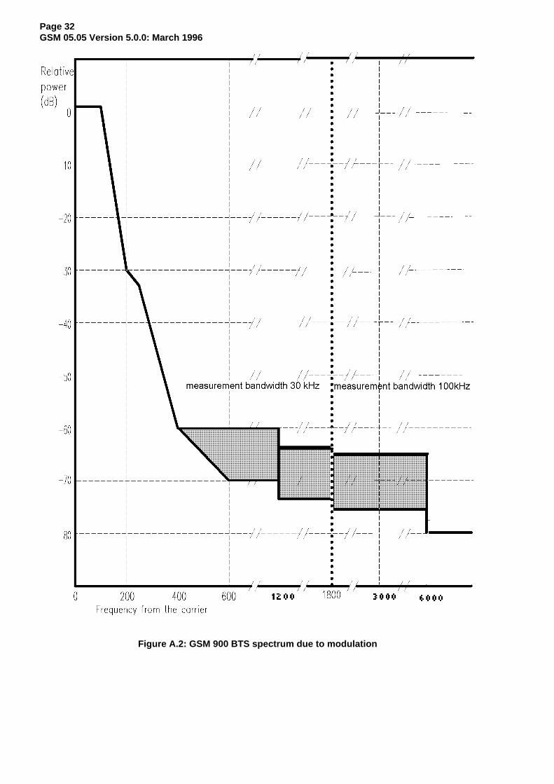
Page 33GSM 05.05 Version 5.0.0: March 1996
Figure A.3: DCS 1800 MS spectrum due to modulation
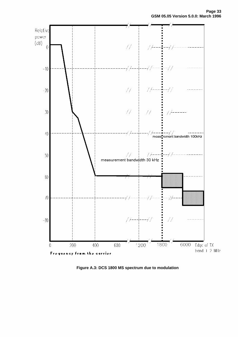
Page 34GSM 05.05 Version 5.0.0: March 1996
Figure A.4: DCS 1800 BTS spectrum due to modulation
Page 35GSM 05.05 Version 5.0.0: March 1996
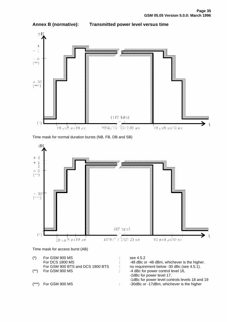
Annex B (normative): Transmitted power level versus time
Time mask for normal duration bursts (NB, FB, DB and SB)
Time mask for access burst (AB)
(*) For GSM 900 MS : see 4.5.2For DCS 1800 MS : -48 dBc or -48 dBm, whichever is the higher.For GSM 900 BTS and DCS 1800 BTS : no requirement below -30 dBc (see 4.5.1).
(**) For GSM 900 MS : -4 dBc for power control level 16,-2dBc for power level 17,-1dBc for power level controls levels 18 and 19
(***) For GSM 900 MS : -30dBc or -17dBm, whichever is the higher
Page 36GSM 05.05 Version 5.0.0: March 1996
Annex C (normative): Propagation conditions
C.1 Simple wideband propagation model
Radio propagation in the mobile radio environment is described by highly dispersive multipath caused byreflection and scattering. The paths between base station and mobile station may be considered to consistof large reflectors and/or scatterers some distance to the MS, giving rise to a number of waves that arrivein the vicinity of the MS with random amplitudes and delays.
Close to the MS these paths are further randomised by local reflections or diffractions. Since the MS willbe moving, the angle of arrival must also be taken into account, since it affects the doppler shiftassociated with a wave arriving from a particular direction. Echos of identical delays arise from reflectorslocated on an ellipse.
The multipath phenomenon may be described in the following way in terms of the time delays and thedoppler shifts associated with each delay:
z t R( )= ∫∫ y(t - T)S(T, f)exp(2i fT)dfdTπ2
where the terms on the right-hand side represent the delayed signals, their amplitudes and dopplerspectra.
It has been shown that the criterion for wide sense stationarity is satisfied for distances of about 10metres. Based on the wide sense stationary uncorrelated scattering (WSSUS) model, the average delayprofiles and the doppler spectra are necessary to simulate the radio channel.
In order to allow practical simulation, the different propagation models will be presented here in thefollowing terms:
1) a discrete number of taps, each determined by their time delay and their average power;
2) the Rayleigh distributed amplitude of each tap, varying according to a doppler spectrum S(f).
C.2 Doppler spectrum types
In this section, we define the two types of doppler spectra which will be used for the modelling of thechannel. Throughout this section the following abbreviations will be used:
- fd = v/λ, represents the maximum doppler shift, with v (in ms-1) representing the vehicle speed, andλ (in m) the wavelength:
The following types are defined:
a) CLASS is the classical doppler spectrum and will be used in all but one case;
(CLASS) S(f) = A/(1-(f/fd)2 )0.5 for f ∈ -fd,fd;
b) RICE is the sum of a classical doppler spectrum and one direct path, such that the total multipathcontribution is equal to that of the direct path. This power spectrum is used for the shortest path ofthe RA model;
(RICE) S(f) = 0.41/(2πfd(1-(f/fd )2 )0.5 ) + 0.91 δ(f - 0.7 fd ) for f ∈ ]-fd , fd.[
Page 37GSM 05.05 Version 5.0.0: March 1996
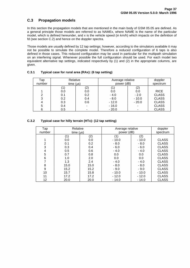
C.3 Propagation models
In this section the propagation models that are mentioned in the main body of GSM 05.05 are defined. Asa general principle those models are referred to as NAMEx, where NAME is the name of the particularmodel, which is defined hereunder, and x is the vehicle speed (in km/h) which impacts on the definition offd (see section C.2) and hence on the doppler spectra.
Those models are usually defined by 12 tap settings; however, according to the simulators available it maynot be possible to simulate the complete model. Therefore a reduced configuration of 6 taps is alsodefined in those cases. This reduced configuration may be used in particular for the multipath simulationon an interfering signal. Whenever possible the full configuration should be used. For each model twoequivalent alternative tap settings, indicated respectively by (1) and (2) in the appropriate columns, aregiven.
C.3.1 Typical case for rural area (RAx): (6 tap setting)
Tapnumber
Relativetime (µs)
Average relativepower (dB)
dopplerspectrum
(1) (2) (1) (2)1 0.0 0.0 0.0 0.0 RICE2 0.1 0.2 - 4.0 - 2.0 CLASS3 0.2 0.4 - 8.0 - 10.0 CLASS4 0.3 0.6 - 12.0 - 20.0 CLASS5 0.4 - - 16.0 - CLASS6 0.5 - - 20.0 - CLASS
C.3.2 Typical case for hilly terrain (HTx): (12 tap setting)
Tapnumber
Relativetime (µs)
Average relativepower (dB)
dopplerspectrum
(1) (2) (1) (2)1 0.0 0.0 - 10.0 - 10.0 CLASS2 0.1 0.2 - 8.0 - 8.0 CLASS3 0.3 0.4 - 6.0 - 6.0 CLASS4 0.5 0.6 - 4.0 - 4.0 CLASS5 0.7 0.8 0.0 0.0 CLASS6 1.0 2.0 0.0 0.0 CLASS7 1.3 2.4 - 4.0 - 4.0 CLASS8 15.0 15.0 - 8.0 - 8.0 CLASS9 15.2 15.2 - 9.0 - 9.0 CLASS10 15.7 15.8 - 10.0 - 10.0 CLASS11 17.2 17.2 - 12.0 - 12.0 CLASS12 20.0 20.0 - 14.0 - 14.0 CLASS
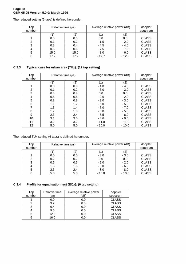
Page 38GSM 05.05 Version 5.0.0: March 1996
The reduced setting (6 taps) is defined hereunder.
Tapnumber
Relative time (µs) Average relative power (dB) dopplerspectrum
(1) (2) (1) (2)1 0.0 0.0 0.0 0.0 CLASS2 0.1 0.2 - 1.5 - 2.0 CLASS3 0.3 0.4 - 4.5 - 4.0 CLASS4 0.5 0.6 - 7.5 - 7.0 CLASS5 15.0 15.0 - 8.0 - 6.0 CLASS6 17.2 17.2 - 17.7 - 12.0 CLASS
C.3.3 Typical case for urban area (TUx): (12 tap setting)
Tapnumber
Relative time (µs) Average relative power (dB) dopplerspectrum
(1) (2) (1) (2)1 0.0 0.0 - 4.0 - 4.0 CLASS2 0.1 0.2 - 3.0 - 3.0 CLASS3 0.3 0.4 0.0 0.0 CLASS4 0.5 0.6 - 2.6 - 2.0 CLASS5 0.8 0.8 - 3.0 - 3.0 CLASS6 1.1 1.2 - 5.0 - 5.0 CLASS7 1.3 1.4 - 7.0 - 7.0 CLASS8 1.7 1.8 - 5.0 - 5.0 CLASS9 2.3 2.4 - 6.5 - 6.0 CLASS10 3.1 3.0 - 8.6 - 9.0 CLASS11 3.2 3.2 - 11.0 - 11.0 CLASS12 5.0 5.0 - 10.0 - 10.0 CLASS
The reduced TUx setting (6 taps) is defined hereunder.
Tapnumber
Relative time (µs) Average relative power (dB) dopplerspectrum
(1) (2) (1) (2)1 0.0 0.0 - 3.0 - 3.0 CLASS2 0.2 0.2 0.0 0.0 CLASS3 0.5 0.6 - 2.0 - 2.0 CLASS4 1.6 1.6 - 6.0 - 6.0 CLASS5 2.3 2.4 - 8.0 - 8.0 CLASS6 5.0 5.0 - 10.0 - 10.0 CLASS
C.3.4 Profile for equalisation test (EQx): (6 tap setting)
Tapnumber
Relative time(µs)
Average relative power(dB)
dopplerspectrum
1 0.0 0.0 CLASS2 3.2 0.0 CLASS3 6.4 0.0 CLASS4 9.6 0.0 CLASS5 12.8 0.0 CLASS6 16.0 0.0 CLASS
Page 39GSM 05.05 Version 5.0.0: March 1996
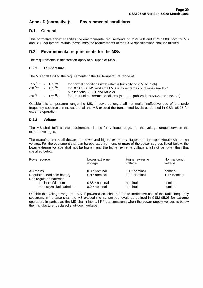
Annex D (normative): Environmental conditions
D.1 General
This normative annex specifies the environmental requirements of GSM 900 and DCS 1800, both for MSand BSS equipment. Within these limits the requirements of the GSM specifications shall be fulfilled.
D.2 Environmental requirements for the MSs
The requirements in this section apply to all types of MSs.
D.2.1 Temperature
The MS shall fulfil all the requirements in the full temperature range of
+15 oC - +35 oC for normal conditions (with relative humidity of 25% to 75%)-10 oC - +55 oC for DCS 1800 MS and small MS units extreme conditions (see IEC
publications 68-2-1 and 68-2-2)-20 oC - +55 oC for other units extreme conditions (see IEC publications 68-2-1 and 68-2-2)
Outside this temperature range the MS, if powered on, shall not make ineffective use of the radiofrequency spectrum. In no case shall the MS exceed the transmitted levels as defined in GSM 05.05 forextreme operation.
D.2.2 Voltage
The MS shall fulfil all the requirements in the full voltage range, i.e. the voltage range between theextreme voltages.
The manufacturer shall declare the lower and higher extreme voltages and the approximate shut-downvoltage. For the equipment that can be operated from one or more of the power sources listed below, thelower extreme voltage shall not be higher, and the higher extreme voltage shall not be lower than thatspecified below.
Power source Lower extreme Higher extreme Normal cond.voltage voltage voltage
AC mains 0.9 * nominal 1.1 * nominal nominalRegulated lead acid battery 0.9 * nominal 1.3 * nominal 1.1 * nominalNon regulated batteries
Leclanché/lithium 0.85 * nominal nominal nominalmercury/nickel cadmium 0.9 * nominal nominal nominal
Outside this voltage range the MS, if powered on, shall not make ineffective use of the radio frequencyspectrum. In no case shall the MS exceed the transmitted levels as defined in GSM 05.05 for extremeoperation. In particular, the MS shall inhibit all RF transmissions when the power supply voltage is belowthe manufacturer declared shut-down voltage.
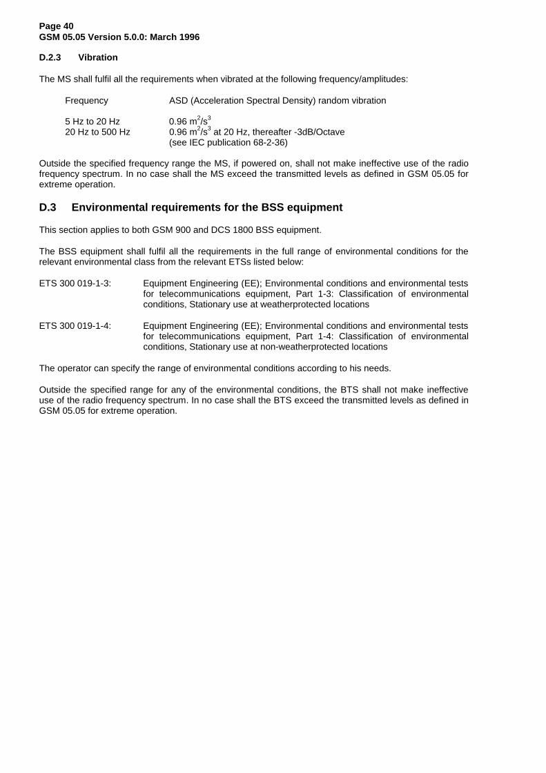
Page 40GSM 05.05 Version 5.0.0: March 1996
D.2.3 Vibration
The MS shall fulfil all the requirements when vibrated at the following frequency/amplitudes:
Frequency ASD (Acceleration Spectral Density) random vibration
5 Hz to 20 Hz 0.96 m2/s3
20 Hz to 500 Hz 0.96 m2/s3 at 20 Hz, thereafter -3dB/Octave(see IEC publication 68-2-36)
Outside the specified frequency range the MS, if powered on, shall not make ineffective use of the radiofrequency spectrum. In no case shall the MS exceed the transmitted levels as defined in GSM 05.05 forextreme operation.
D.3 Environmental requirements for the BSS equipment
This section applies to both GSM 900 and DCS 1800 BSS equipment.
The BSS equipment shall fulfil all the requirements in the full range of environmental conditions for therelevant environmental class from the relevant ETSs listed below:
ETS 300 019-1-3: Equipment Engineering (EE); Environmental conditions and environmental testsfor telecommunications equipment, Part 1-3: Classification of environmentalconditions, Stationary use at weatherprotected locations
ETS 300 019-1-4: Equipment Engineering (EE); Environmental conditions and environmental testsfor telecommunications equipment, Part 1-4: Classification of environmentalconditions, Stationary use at non-weatherprotected locations
The operator can specify the range of environmental conditions according to his needs.
Outside the specified range for any of the environmental conditions, the BTS shall not make ineffectiveuse of the radio frequency spectrum. In no case shall the BTS exceed the transmitted levels as defined inGSM 05.05 for extreme operation.
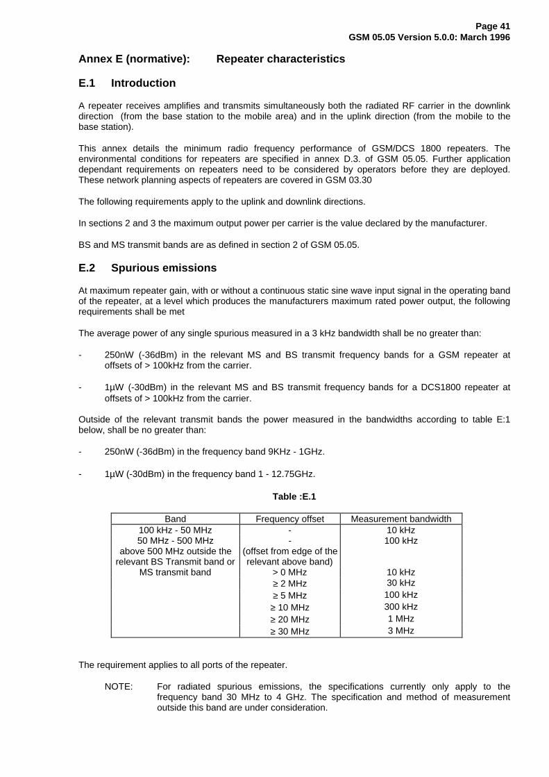
Page 41GSM 05.05 Version 5.0.0: March 1996
Annex E (normative): Repeater characteristics
E.1 Introduction
A repeater receives amplifies and transmits simultaneously both the radiated RF carrier in the downlinkdirection (from the base station to the mobile area) and in the uplink direction (from the mobile to thebase station).
This annex details the minimum radio frequency performance of GSM/DCS 1800 repeaters. Theenvironmental conditions for repeaters are specified in annex D.3. of GSM 05.05. Further applicationdependant requirements on repeaters need to be considered by operators before they are deployed.These network planning aspects of repeaters are covered in GSM 03.30
The following requirements apply to the uplink and downlink directions.
In sections 2 and 3 the maximum output power per carrier is the value declared by the manufacturer.
BS and MS transmit bands are as defined in section 2 of GSM 05.05.
E.2 Spurious emissions
At maximum repeater gain, with or without a continuous static sine wave input signal in the operating bandof the repeater, at a level which produces the manufacturers maximum rated power output, the followingrequirements shall be met
The average power of any single spurious measured in a 3 kHz bandwidth shall be no greater than:
- 250nW (-36dBm) in the relevant MS and BS transmit frequency bands for a GSM repeater atoffsets of > 100kHz from the carrier.
- 1µW (-30dBm) in the relevant MS and BS transmit frequency bands for a DCS1800 repeater atoffsets of > 100kHz from the carrier.
Outside of the relevant transmit bands the power measured in the bandwidths according to table E:1below, shall be no greater than:
- 250nW (-36dBm) in the frequency band 9KHz - 1GHz.
- 1µW (-30dBm) in the frequency band 1 - 12.75GHz.
Table :E.1
Band Frequency offset Measurement bandwidth100 kHz - 50 MHz - 10 kHz50 MHz - 500 MHz - 100 kHz
above 500 MHz outside the (offset from edge of therelevant BS Transmit band or relevant above band)
MS transmit band > 0 MHz 10 kHz≥ 2 MHz 30 kHz≥ 5 MHz 100 kHz
≥ 10 MHz 300 kHz≥ 20 MHz 1 MHz≥ 30 MHz 3 MHz
The requirement applies to all ports of the repeater.
NOTE: For radiated spurious emissions, the specifications currently only apply to thefrequency band 30 MHz to 4 GHz. The specification and method of measurementoutside this band are under consideration.
Page 42GSM 05.05 Version 5.0.0: March 1996
E.3 Intermodulation products
At maximum repeater gain, with two continuous static sine wave input signals in the operating band of therepeater, at equal levels which produce the maximum rated power output per carrier, the average powerof any intermodulation products measured in a 3 kHz bandwidth shall be no greater than:
- 250nW (-36dBm) in the frequency band 9 kHz - 1 GHz.
- 1µW (-30dBm) in the frequency band 1 - 12.75 GHz.
When the two input signals are simultaneously increased by 10dB each, the requirements shall still bemet
The requirement applies to all ports of the repeater.
E.4 Out of band gain
The following requirements apply at all frequencies from 9KHz to 12.75GHz excluding the relevanttransmit bands.
The net out of band gain in both directions through the repeater shall be less than +50dB at 400kHz,+40dB at 600kHz, +35dB at 1MHz and +25dB at 5MHz offset and greater from the edges of the BS andMS transmit bands.
In special circumstances additional filtering may be required out of band and reference should be made toGSM 03.30.
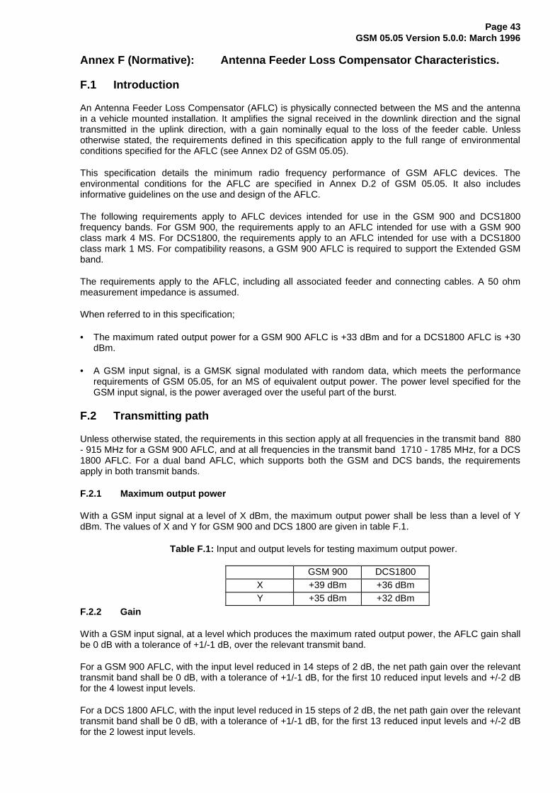
Page 43GSM 05.05 Version 5.0.0: March 1996
Annex F (Normative): Antenna Feeder Loss Compensator Characteristics.
F.1 Introduction
An Antenna Feeder Loss Compensator (AFLC) is physically connected between the MS and the antennain a vehicle mounted installation. It amplifies the signal received in the downlink direction and the signaltransmitted in the uplink direction, with a gain nominally equal to the loss of the feeder cable. Unlessotherwise stated, the requirements defined in this specification apply to the full range of environmentalconditions specified for the AFLC (see Annex D2 of GSM 05.05).
This specification details the minimum radio frequency performance of GSM AFLC devices. Theenvironmental conditions for the AFLC are specified in Annex D.2 of GSM 05.05. It also includesinformative guidelines on the use and design of the AFLC.
The following requirements apply to AFLC devices intended for use in the GSM 900 and DCS1800frequency bands. For GSM 900, the requirements apply to an AFLC intended for use with a GSM 900class mark 4 MS. For DCS1800, the requirements apply to an AFLC intended for use with a DCS1800class mark 1 MS. For compatibility reasons, a GSM 900 AFLC is required to support the Extended GSMband.
The requirements apply to the AFLC, including all associated feeder and connecting cables. A 50 ohmmeasurement impedance is assumed.
When referred to in this specification;
• The maximum rated output power for a GSM 900 AFLC is +33 dBm and for a DCS1800 AFLC is +30dBm.
• A GSM input signal, is a GMSK signal modulated with random data, which meets the performancerequirements of GSM 05.05, for an MS of equivalent output power. The power level specified for theGSM input signal, is the power averaged over the useful part of the burst.
F.2 Transmitting path
Unless otherwise stated, the requirements in this section apply at all frequencies in the transmit band 880- 915 MHz for a GSM 900 AFLC, and at all frequencies in the transmit band 1710 - 1785 MHz, for a DCS1800 AFLC. For a dual band AFLC, which supports both the GSM and DCS bands, the requirementsapply in both transmit bands.
F.2.1 Maximum output power
With a GSM input signal at a level of X dBm, the maximum output power shall be less than a level of YdBm. The values of X and Y for GSM 900 and DCS 1800 are given in table F.1.
Table F.1: Input and output levels for testing maximum output power.
GSM 900 DCS1800X +39 dBm +36 dBmY +35 dBm +32 dBm
F.2.2 Gain
With a GSM input signal, at a level which produces the maximum rated output power, the AFLC gain shallbe 0 dB with a tolerance of +1/-1 dB, over the relevant transmit band.
For a GSM 900 AFLC, with the input level reduced in 14 steps of 2 dB, the net path gain over the relevanttransmit band shall be 0 dB, with a tolerance of +1/-1 dB, for the first 10 reduced input levels and +/-2 dBfor the 4 lowest input levels.
For a DCS 1800 AFLC, with the input level reduced in 15 steps of 2 dB, the net path gain over the relevanttransmit band shall be 0 dB, with a tolerance of +1/-1 dB, for the first 13 reduced input levels and +/-2 dBfor the 2 lowest input levels.
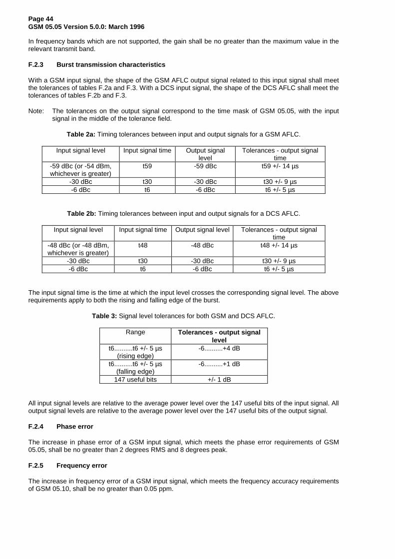
Page 44GSM 05.05 Version 5.0.0: March 1996
In frequency bands which are not supported, the gain shall be no greater than the maximum value in therelevant transmit band.
F.2.3 Burst transmission characteristics
With a GSM input signal, the shape of the GSM AFLC output signal related to this input signal shall meetthe tolerances of tables F.2a and F.3. With a DCS input signal, the shape of the DCS AFLC shall meet thetolerances of tables F.2b and F.3.
Note: The tolerances on the output signal correspond to the time mask of GSM 05.05, with the inputsignal in the middle of the tolerance field.
Table 2a: Timing tolerances between input and output signals for a GSM AFLC.
Input signal level Input signal time Output signallevel
Tolerances - output signaltime
-59 dBc (or -54 dBm,whichever is greater)
t59 -59 dBc t59 +/- 14 µs
-30 dBc t30 -30 dBc t30 +/- 9 µs-6 dBc t6 -6 dBc t6 +/- 5 µs
Table 2b: Timing tolerances between input and output signals for a DCS AFLC.
Input signal level Input signal time Output signal level Tolerances - output signaltime
-48 dBc (or -48 dBm,whichever is greater)
t48 -48 dBc t48 +/- 14 µs
-30 dBc t30 -30 dBc t30 +/- 9 µs-6 dBc t6 -6 dBc t6 +/- 5 µs
The input signal time is the time at which the input level crosses the corresponding signal level. The aboverequirements apply to both the rising and falling edge of the burst.
Table 3: Signal level tolerances for both GSM and DCS AFLC.
Range Tolerances - output signallevel
t6..........t6 +/- 5 µs(rising edge)
-6..........+4 dB
t6..........t6 +/- 5 µs(falling edge)
-6..........+1 dB
147 useful bits +/- 1 dB
All input signal levels are relative to the average power level over the 147 useful bits of the input signal. Alloutput signal levels are relative to the average power level over the 147 useful bits of the output signal.
F.2.4 Phase error
The increase in phase error of a GSM input signal, which meets the phase error requirements of GSM05.05, shall be no greater than 2 degrees RMS and 8 degrees peak.
F.2.5 Frequency error
The increase in frequency error of a GSM input signal, which meets the frequency accuracy requirementsof GSM 05.10, shall be no greater than 0.05 ppm.
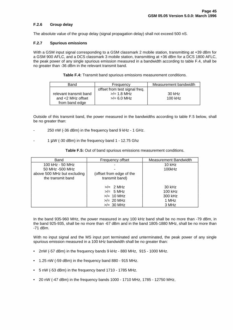
Page 45GSM 05.05 Version 5.0.0: March 1996
F.2.6 Group delay
The absolute value of the group delay (signal propagation delay) shall not exceed 500 nS.
F.2.7 Spurious emissions
With a GSM input signal corresponding to a GSM classmark 2 mobile station, transmitting at +39 dBm fora GSM 900 AFLC, and a DCS classmark 3 mobile station, transmitting at +36 dBm for a DCS 1800 AFLC,the peak power of any single spurious emission measured in a bandwidth according to table F.4, shall beno greater than -36 dBm in the relevant transmit band.
Table F.4: Transmit band spurious emissions measurement conditions.
Band Frequency Measurement bandwidthoffset from test signal freq.
relevant transmit band >/= 1.8 MHz 30 kHzand <2 MHz offsetfrom band edge
>/= 6.0 MHz 100 kHz
Outside of this transmit band, the power measured in the bandwidths according to table F.5 below, shallbe no greater than:
- 250 nW (-36 dBm) in the frequency band 9 kHz - 1 GHz.
- 1 µW (-30 dBm) in the frequency band 1 - 12.75 Ghz
Table F.5: Out of band spurious emissions measurement conditions.
Band Frequency offset Measurement Bandwidth100 kHz - 50 MHz - 10 kHz50 MHz -500 MHz - 100kHz
above 500 MHz but excludingthe transmit band
(offset from edge of thetransmit band)
>/= 2 MHz 30 kHz>/= 5 MHz 100 kHz>/= 10 MHz 300 kHz>/= 20 MHz 1 MHz>/= 30 MHz 3 MHz
In the band 935-960 MHz, the power measured in any 100 kHz band shall be no more than -79 dBm, inthe band 925-935, shall be no more than -67 dBm and in the band 1805-1880 MHz, shall be no more than-71 dBm.
With no input signal and the MS input port terminated and unterminated, the peak power of any singlespurious emission measured in a 100 kHz bandwidth shall be no greater than:
• 2nW (-57 dBm) in the frequency bands 9 kHz - 880 MHz, 915 - 1000 MHz.
• 1.25 nW (-59 dBm) in the frequency band 880 - 915 MHz.
• 5 nW (-53 dBm) in the frequency band 1710 - 1785 MHz.
• 20 nW (-47 dBm) in the frequency bands 1000 - 1710 MHz, 1785 - 12750 MHz,
Page 46GSM 05.05 Version 5.0.0: March 1996
F.2.8 VSWR
The VSWR shall be less than 1.7:1 at the RF port of the device which is intended to be connected to theMS. The VSWR shall be less than 2:1 at the RF port of the device which is intended to be connected tothe antenna.
F.2.9 Stability
The AFLC shall be unconditionally stable.
F.3 Receiving path
Unless otherwise stated, the requirements in this section apply at all frequencies in the receive band 925- 960 MHz for a GSM 900 AFLC, and at all frequencies in the receive band 1805 - 1880 MHz, for a DCS1800 AFLC. For a dual band AFLC, which supports both the GSM and DCS bands, the requirementsapply in both receive bands.
F.3.1 Gain
With a GSM input signal at any level in the range -102 dBm to -20 dBm for an GSM 900 AFLC and -100dBm to -20 dBm for a DCS1800 AFLC, the gain shall be 0 dB with a tolerance of +1/-1 dB.
For test purposes, it is sufficient to use a CW signal to test this requirement.
F.3.2 Noise figure
The noise figure shall be less than 7 dB for a GSM 900 AFLC and less than 7 dB for a DCS1800 AFLC.
F.3.3 Group delay
The absolute value of the group delay (signal propagation delay) shall not exceed 500 nS.
F.3.4 Intermodulation performance
The output third order intercept point shall be greater than -10 dBm.
F.3.5 VSWR
The VSWR shall be less than 1.7:1 at the RF port of the device which is intended to be connected to theMS. The VSWR shall be less than 2:1 at the RF port of the device which is intended to be connected tothe antenna.
F.3.6 Stability
The AFLC shall be unconditionally stable.
F.4 Guidelines (Informative)
The specifications of the AFLC, have been developed to ensure that a generic AFLC causes minimaldegradation of the parametric performance of the MS, to which it is connected,
The following should be clearly marked on the AFLC:
• The intended band(s) of operation.
• The classmark of the MS, to which it designed to be connected.
When installed correctly the AFLC can provide enhancement of the MS to BTS link in vehicularinstallations. However, it is not guaranteed that an AFLC, which meets the requirements of thisspecification, will provide a performance improvement for all of the different GSM MS implementationsand installations.
Page 47GSM 05.05 Version 5.0.0: March 1996
Some MS implementations significantly exceed the performance requirements of GSM 05.05. e.g. withrespect to reference sensitivity performance. A purely passive feeder of low loss cable, may provide thebest performance for some implementations. The benefits of installing an AFLC in a vehicular application,can only be assessed on a case by case basis.
When used, the AFLC should only be installed in the type approved configuration, with the minimumamount of additional cabling.
When designing an AFLC to be used with a GSM MS, the best downlink performance will be obtained ifthe low noise amplifier is situated as closely as possible to the output of the antenna.
Page 48GSM 05.05 Version 5.0.0: March 1996
History
Document history
February 1996 Creation of Version 5.0.0
March 1996 Publication of Version 5.0.0
ISBN 2-7437-0579-5Dépôt légal : Mars 1996