gsm 07.05 - version 5.0.0 - digital cellular …€¦ · · 2000-02-02gsm 07.05 version 5.0.0:...
TRANSCRIPT

GSM GSM 07.05
TECHNICAL July 1996
SPECIFICATION Version 5.0.0
Source: ETSI TC-SMG Reference: TS/SMG-040705Q
ICS: 33.060.50
Key words: Digital cellular telecommunications system, Global System for Mobile communications (GSM)
Digital cellular telecommunications system (Phase 2+);Use of Data Terminal Equipment - Data Circuit terminating;
Equipment (DTE - DCE) interface forShort Message Service (SMS) and Cell Broadcast Service (CBS)
(GSM 07.05)
ETSI
European Telecommunications Standards Institute
ETSI Secretariat
Postal address: F-06921 Sophia Antipolis CEDEX - FRANCEOffice address: 650 Route des Lucioles - Sophia Antipolis - Valbonne - FRANCEX.400: c=fr, a=atlas, p=etsi, s=secretariat - Internet: [email protected]
Tel.: +33 92 94 42 00 - Fax: +33 93 65 47 16
Copyright Notification: No part may be reproduced except as authorized by written permission. The copyright and theforegoing restriction extend to reproduction in all media.
© European Telecommunications Standards Institute 1996. All rights reserved.

Page 2GSM 07.05 Version 5.0.0: July 1996
Whilst every care has been taken in the preparation and publication of this document, errors in content,typographical or otherwise, may occur. If you have comments concerning its accuracy, please write to"ETSI Editing and Committee Support Dept." at the address shown on the title page.

Page 3GSM 07.05 Version 5.0.0: July 1996
Contents
Foreword ...........................................................................................................................................7
0 Scope.......................................................................................................................................90.1 Normative references.................................................................................................100.2 Abbreviations ............................................................................................................10
1 Reference configuration ...........................................................................................................111.1 V.24 Interface Circuits ...............................................................................................11
1.1.1 Circuit definitions for the SMS Block mode................................................111.1.2 Circuit definitions for the SMS Text and PDU modes..................................12
2 SMS Block Mode.....................................................................................................................132.1 Beginning and ending of SMS/CBS Block Mode ...........................................................13
2.1.1 Beginning SMS/CBS Block Mode.............................................................132.1.2 Returning from SMS/CBS Block Mode To Default Mode............................13
2.2 Protocol description...................................................................................................142.3 Requesting messages already held in the Mobile Termination .......................................15
2.3.1 Requesting List Of Messages..................................................................152.3.2 Requesting Transfer Of Messages...........................................................15
2.3.2.1 Requesting Transfer Of A Specific Message.....................152.3.2.2 Requesting Transfer Of All Messages ..............................16
2.3.3 Requesting Diversion Of Incoming Messages............................................162.3.3.1 Requesting SMS Messages.............................................162.3.3.2 Requesting CBS Messages .............................................172.3.3.3 Requesting indication of message arrival...........................17
2.3.4 Requesting Transfer Into Mobile Termination ............................................182.3.5 Requesting Deletion Of Messages ...........................................................18
2.4 Message functional definitions and contents.................................................................192.4.1 Commands Issued By The Terminal Equipment.........................................19
2.4.1.1 List Request ...................................................................202.4.1.2 Get Message .................................................................202.4.1.3 Get First Message..........................................................202.4.1.4 Get Next Message..........................................................202.4.1.5 Transfer Inc SMS............................................................202.4.1.6 Indicate Inc SMS ............................................................212.4.1.7 Transfer Inc CBS ............................................................212.4.1.8 Insert SMS.....................................................................212.4.1.9 Delete message..............................................................222.4.1.10 Unable to process...........................................................222.4.1.11 End SMS Mode ..............................................................222.4.1.12 Acknowledge Message ...................................................22
2.4.2 Responses/Indications Issued By The MT ................................................232.4.2.1 Message List..................................................................242.4.2.2 Message........................................................................242.4.2.3 Get Message Failure.......................................................242.4.2.4 Inc Message...................................................................252.4.2.5 Message Arrived.............................................................252.4.2.6 Insert SMS Complete......................................................252.4.2.7 Insert SMS Failure ..........................................................252.4.2.8 Delete Message Complete ..............................................262.4.2.9 Delete Message Failure...................................................262.4.2.10 Unable To Process..........................................................262.4.2.11 End SMS Mode ..............................................................262.4.2.12 Request Confirmed .........................................................27
Page 4GSM 07.05 Version 5.0.0: July 1996
2.5 General message format and information elements coding............................................282.5.1 Message Type .......................................................................................282.5.2 Other Information Elements .....................................................................29
2.5.2.1 Short Message Reference ...............................................292.5.2.2 SMS Transfer Type.........................................................302.5.2.3 Indication Type ...............................................................312.5.2.4 Insert Type.....................................................................322.5.2.5 Short Message Index ......................................................332.5.2.6 Short Message Data .......................................................352.5.2.7 Cause ............................................................................372.5.2.8 Index Count ....................................................................382.5.2.9 CBS Transfer Type .........................................................382.5.2.10 Page Index .....................................................................392.5.2.11 Last Short Message........................................................392.5.2.12 Confirm Type..................................................................402.5.2.13 TP-Failure Cause ............................................................41
3. Text Mode...............................................................................................................................423.1 Parameter Definitions.................................................................................................423.2 General Configuration Commands...............................................................................45
3.2.1 Select Message Service +CSMS .............................................................453.2.2 Preferred Message Storage +CPMS........................................................463.2.3 Message Format +CMGF .......................................................................463.2.4 Enter SMS Block Mode Protocol +CESP..................................................473.2.5 Message Service Failure Result Code +CMS ERROR...............................473.2.6 Informative Examples..............................................................................48
3.3 Message Configuration Commands.............................................................................493.3.1 Service Centre Address +CSCA ..............................................................493.3.2 Set Text Mode Parameters +CSMP.........................................................493.3.3 Show Text Mode Parameters +CSDH ......................................................503.3.4 Select Cell Broadcast Message Types +CSCB.........................................503.3.5 Save Settings +CSAS .............................................................................513.3.6 Restore Settings +CRES.........................................................................513.3.7 Informative Examples..............................................................................52
3.4 Message Receiving and Reading Commands...............................................................533.4.1 New Message Indications to TE +CNMI ...................................................533.4.2 List Messages +CMGL ...........................................................................563.4.3 Read Message +CMGR..........................................................................573.4.4 Informative Examples..............................................................................58
3.5 Message Sending and Writing Commands...................................................................593.5.1 Send Message +CMGS ..........................................................................593.5.2 Send Message from Storage +CMSS ......................................................603.5.3 Write Message to Memory +CMGW ........................................................613.5.4 Delete Message +CMGD ........................................................................613.5.5 Send Command +CMGC.........................................................................623.5.6 Informative Examples..............................................................................63
4 PDU Mode ..............................................................................................................................644.1 List Messages +CMGL ..............................................................................................644.2 Read Message +CMGR.............................................................................................644.3 Send Message +CMGS .............................................................................................654.4 Write Message to Memory +CMGW...........................................................................664.5 Send Command +CMGC............................................................................................66
Annex A (Normative): Character Set Conversions for SMS Text Mode.............................................67
Annex B (Informative): Example of processing a data block..............................................................70
B.1 Example state diagrams for the block receiver ..........................................................................70

Page 5GSM 07.05 Version 5.0.0: July 1996
B.2 Example of coding and decoding a data block............................................................................70
History .............................................................................................................................................74

Page 6GSM 07.05 Version 5.0.0: July 1996
Blank page

Page 7GSM 07.05 Version 5.0.0: July 1996
Foreword
This Global System for Mobile communications Technical Specification (GTS) has been produced by theSpecial Mobile Group (SMG) Technical Committee (TC) of the European Telecommunications StandardsInstitute (ETSI).
This GTS outlines the use of data terminal equipment and specifies the terminal (DTE-DCE) interface forShort Message and Short Message Cell Broadcast Services within the digital cellular telecommunicationssystem (Phase 2/Phase 2+).
This GTS is a TC-SMG approved GSM technical specification version 5, which contains GSM Phase 2+enhancements/features to the version 4 GSM technical specification. The ETS from which this Phase 2+GTS has evolved is Phase 2 GSM ETS 300 585 edition 4 (GSM 07.05 version 4.7.0).
GTS are produced by TC-SMG to enable the GSM Phase 2 + specifications to become publicly available,prior to submission for the formal ETSI standards approval procedure to become EuropeanTelecommunications Standards (ETS). This ensures the earliest possible access to GSM Phase 2+specifications for all Manufacturers, Network operators and implementors of the Global System for Mobilecommunications.
The contents of this GTS are subject to continuing work within TC-SMG and may change following formalTC-SMG approval. Should TC-SMG modify the contents of this GTS it will then be republished by ETSIwith an identifying change of release date and an increase in version number as follows:
Version 5.x.y
where:y the third digit is incremented when editorial only changes have been incorporated in the
specification;
x the second digit is incremented for all other types of changes, i.e. technical enhancements,corrections, updates, etc.
NOTE: TC-SMG has produced documents which give the technical specifications for theimplementation of the digital cellular telecommunications system. Historically, thesedocuments have been identified as GSM Technical Specifications (GSM-TSs). TheseTSs may have subsequently become I-ETSs (Phase 1), or ETSs/ETSI TechnicalReports (ETRs) (Phase 2). TC-SMG has also produced ETSI GSM TSs which give thetechnical specifications for the implementation of Phase 2+ enhancements of the digitalcellular telecommunications system. These version 5.x.x GSM Technical Specificationsmay be referred to as GTSs.

Page 8GSM 07.05 Version 5.0.0: July 1996
Blank page

Page 9GSM 07.05 Version 5.0.0: July 1996
0 Scope
This European Telecommunication Standard (ETS) defines three interface protocols for control of SMSfunctions within a GSM mobile telephone from a remote terminal via an asynchronous interface.
Section 2 defines a binary protocol ("Block Mode"). The protocol includes error protection and is suitablefor use where the link may not be completely reliable. It will be of particular use where control of remotedevices is required. Efficient transfer of binary encoded user data is possible.
Section 3 defines a character-based interfaced based on "AT" commands ("Text Mode"). This mode issuitable for unintelligent terminals or terminal emulators, and for application software built on commandstructures like those defined in V.25ter. Some of the commands defined in Section 3 will also be useful forimplementations of Section 2 and/or Section 4, for example enabling an indication of incoming SMSmessages.
Section 4 defines a character-based interface with hex-encoded binary transfer of message blocks ("PDUMode"). This mode is suitable for software drivers based on AT command structures which do notunderstand the content of the message blocks and can only pass them between the MT and "upper level"software resident in the TE.
In all three modes, the terminal is considered to be in control for SMS/CBS transactions.
This specification considers the mobile termination to be a single entity. Other GSM TechnicalSpecifications describe the split of functionality between the mobile equipment and SIM.
The three "modes" referred to above, are represented in figure 0.1/GSM 07.05.
The "Block mode" is a self contained mode in its own right, and when entered, control will remain withinthat mode until the procedures to exit the mode are executed, after which control is returned to the V.25ter"command" state or "on-line command" state.
The "Text" and "PDU" modes are not in themselves V.25ter states but are simply sets of commands whichwill operate in either the V.25ter "command" state or "on-line command" state. The "Text" and "PDU"modes are transitory states and after each operation, control is automatically returned to the V.25ter"command" state or "on-line command" state. Whilst in the V.25ter command state, the MS is available tohandle incoming and outgoing calls such as Data or Facsimile.
S M STe xt
M od e
S M SP D UM o de
S M S Blo ck M o d e
V .2 5 te r"c om m an d" sta te
an d "o n- lin e c om m an d" state
Figure 0.1/GSM 07.05: Block, Text and PDU modes

Page 10GSM 07.05 Version 5.0.0: July 1996
0.1 Normative references
This ETS incorporates by dated and undated reference, provisions from other publications. Thesenormative references are cited at the appropriate places in the text and the publications are listedhereafter. For dated references, subsequent amendments to or revisions of any of these publications applyto this ETS only when incorporated in it by amendment or revision. For undated references, the latestedition of the publication referred to applies.
[1] GSM 01.04 (ETR 100): "Digital cellular telecommunication system (Phase 2);Abbreviations and acronyms".
[2] GSM 03.38 (ETS 300 628): "Digital cellular telecommunication system(Phase 2); Alphabet and language specific information".
[3] GSM 03.40 (ETS 300 536): "Digital cellular telecommunication system(Phase 2); Technical realization of the Short Message Service (SMS) Point toPoint (PP)".
[4] GSM 03.41 (ETS 300 537): "Digital cellular telecommunication system(Phase 2); Technical realization of Short Message Service Cell Broadcast(SMSCB)".
[5] GSM 04.08 (ETS 300 557): "Digital cellular telecommunication system(Phase 2); Mobile radio interface layer 3 specification".
[6] GSM 04.11 (ETS 300 559): "Digital cellular telecommunication system(Phase 2); Point-to-Point (PP) Short Message Service (SMS) support on mobileradio interface".
[7] GSM 04.12 (ETS 300 560): "Digital cellular telecommunication system(Phase 2); Short Message Service Cell Broadcast (SMSCB) support on themobile radio interface".
[8] GSM 07.01 (ETS 300 582): "Digital cellular telecommunication system(Phase 2); General on Terminal Adaptation Functions (TAF) for Mobile Stations(MS)".
[9] GSM 07.07 (ETS 300 642): "Digital cellular telecommunication system(Phase 2); AT command set for GSM Mobile Equipment (ME)".
[10] GSM 11.11 (ETS 300 608): "Digital cellular telecommunication system(Phase 2); Specification of the Subscriber Identity Module - Mobile Equipment(SIM - ME) interface".
[11] CCITT Recommendation V.25ter: "Serial Asynchronous Automatic Dialling AndControl"
[12] CCITT Recommendation V.24: "List of definitions for interchange circuitsbetween data terminal equipment (DTE) and data circuit-terminating equipment".
[13] CCITT Recommendation E.164: "Numbering plan for the ISDN era".
[14] CCITT Recommendation E.163: "Numbering plan for the international telephoneservice".
0.2 Abbreviations
Abbreviations used in this specification are listed in GSM 01.04 [1].

Page 11GSM 07.05 Version 5.0.0: July 1996
1 Reference configuration
�����������������������02%,/(�67$7,21��������������������!¸¶¶¶¶¶¶¶¶¶¶¶¶¶¶¹��������������������������¸¶¶¶¶¶¶¶¶¶¶¶¶¶¶¹·��������������·��������������������������·��������������··��02%,/(������·��������������������������·��������������··�(48,30(17����·��������������������������·�7(50,1$/�����·¼¶¶¶¶¶¶¹�������¼¶¶¶¶¶¶¶¶¶¶¶¶¶¶¶¶¶¶¶¶¶¶¶¶¶¶½�(48,30(17����··������·�������·��'&(�'7(�,17(5)$&(�������·��������������··6,0���·�������·��������������������������·��������������·º¶¶¶¶¶¶¿¶¶¶¶¶¶¶»��������������������������º¶¶¶¶¶¶¶¶¶¶¶¶¶¶»
02%,/(�7(50,1$7,21��07��Figure 1: Reference configuration
The mobile termination consists of the mobile equipment (ME) and the SIM. Messages may be stored ineither, but this specification does not distinguish between messages stored in the SIM or in the ME. Themanagement of message storage in the two parts of the mobile termination is a matter for the mobiletermination implementation.
1.1 V.24 Interface Circuits
The operation of the CCITT V.24 blue book interface circuits for SMS is shown in table 1.1/GSM 07.05.
Table 1.1/GSM 07.05: Use of V.24 interface circuits
V.24 CIRCUIT DESCRIPTION TE to MT MT to TE
CT102 signal ground x x
CT103 TXD x
CT104 RXD x
CT105 RTS x
CT106 CTS x
CT107 DSR x
CT108.2 DTR x
CT109 DCD x
NOTE: CT105 at the TE is connected to CT133 at the MT
1.1.1 Circuit definitions for the SMS Block mode
CT103All commands from the TE to the MT are transferred across this circuit. Inband flow control is notpermitted during Block Mode.
CT104All responses/indications from the MT to the TE are transferred across this circuit. Inband flow control isnot permitted during Block Mode.

Page 12GSM 07.05 Version 5.0.0: July 1996
CT105This circuit allows the TE to flow control the MT when in the Block Mode and at other times if hardwareflow control is enabled.
CT106This circuit allows the MT to flow control the TE when in the Block Mode and at other times if hardwareflow control is enabled.
CT107This circuit shall be set to the ON condition before entry into the Block Mode, and shall remain in the ONcondition during Block Mode. If the TE detects that this circuit returns to the OFF condition during the blockmode then the TE shall return CT108.2 to the OFF condition and exit the Block Mode.
CT108.2This circuit shall be set in the ON condition before the AT+CESP command is sent from the TE to begin theBlock Mode, and shall be maintained in the ON condition during the Block Mode. It shall be returned to theOFF condition after the command 'END SMS MODE' has been accepted and acknowledged by the MT. Ifthe MT detects that this circuit returns to the OFF condition during the Block Mode then the MT shall exitthe Block Mode.
CT109This circuit shall be set to the ON condition before entry into the Block Mode and remain in the ONcondition during the Block Mode. If the TE detects that this circuit returns to the OFF condition during theBlock Mode then the TE shall return CT108.2 to the OFF condition and shall exit the Block Mode.
1.1.2 Circuit definitions for the SMS Text and PDU modes
Only circuits CT102, CT103 and CT104 are mandatory for the Text and PDU modes. The functionality andoperation of other circuits shall be in accordance with V.25ter.

Page 13GSM 07.05 Version 5.0.0: July 1996
2 SMS Block Mode
2.1 Beginning and ending of SMS/CBS Block Mode
2.1.1 Beginning SMS/CBS Block Mode
As described in TS GSM 07.01, the DTE/DCE interface is normally associated with the terminal adaptationfunction (TAF), if such a function is available. When no data connection is in progress, and the terminalequipment wishes to enter SMS/CBS mode, the command 'AT+CESP' shall be issued by the TE throughthe DTE/DCE interface requesting that the Block mode protocol described in this specification is to beused. The syntax of this command is further described in section 3.2.4 later. The syntax for thesecommands is derived from V.25ter, i.e. the command is encoded as an IA5 character string together withdelimiters as described in V.25ter.
Upon receipt of this command, the mobile termination shall respond as follows:
If the mobile termination supports SMS/CBS block mode commands, responses and indications asdescribed in this technical specification, it shall respond with 'OK' and enter the SMS/CBS mode.If the mobile termination does not support SMS/CBS block mode commands, responses andindications as described in this technical specification, it shall respond with 'ERROR' and remain inthe current mode..
If the SMS/CBS block mode command is accepted by the mobile termination, then all further commands,responses and indications shall be as defined in section 2 of this technical specification. These SMS/CBSmode commands, responses and indications use 8-bit encoded data and not IA5 characters.
2.1.2 Returning from SMS/CBS Block Mode To Default Mode
When the terminal equipment wishes to return to default mode from SMS/CBS mode, it shall issue thecommand 'END SMS MODE', described in section 2.4.1.11. The mobile termination shall respond with 'OK'to indicate that the DTE/DCE interface has returned to default mode. The TE shall change back to defaultmode whether or not such a response is received.
The TE may also indicate that it has exit from the SMS/CBS mode through the use of CT 108/2 (seesection 1.1)
If an incoming data call arrives while the DTE/DCE interface is set to SMS/CBS mode, then the mobiletermination may autonomously issue the 'END SMS MODE' indication (section 2.4.2.11) and revert todefault mode in order to connect the data call through the TAF.
The MT may exit from SMS/CBS mode autonomously if the power to the MT is switched off and then onagain. In addition, the MT manufacturer may provide MMI to change the mode back to the default mode.In the latter case, the MT shall issue the 'END SMS MODE' indication (section 2.4.2.11) and exit theSMS/CBS mode immediately.
The MT may also indicate that it has exit from the SMS/CBS mode through the use of CT 107 andCT 109 (see section 1.1).
A BREAK condition in either direction at the DTE/DCE interface shall cause the TE and the MT to exit fromthe SMS/CBS block mode and return to the default mode.
In the event where the TE or the MT find themselves unable to recover from a protocol error then eitherentity may exit the SMS/CBS mode using any of the mechanisms described above. Confirmation of defaultmode operation will be achieved through the use of AT commands and responses.

Page 14GSM 07.05 Version 5.0.0: July 1996
2.2 Protocol description
The communication path between the MT and the TE across the DTE/DCE interface should be quitereliable if it uses a short wire link. However, to ensure that the low error rate does not cause malfunction,the following error protection scheme is provided.
Each message sent from the MT to the TE or vice-versa consists of a data block (DATA) and block checksum (BCS, see figure 2.2.1). In the following description the notation DLE, STX, NUL and ETX refer tocontrol characters having the values 10 02 00 and 03 hexadecimal respectively.
�������������������'$7$�����������������!����%&6��!�����¸¶¶¶¶¾¶¶¶¶¾¶¶¶¶¶¶¶¶¶¶���¶¶¶¶¶¶¶¾¶¶¶¶¾¶¶¶¶¾¶¶¶¶¾¶¶¶¶¹�����·'/(�·67;�·��0(66$*(�&217(17���·'/(�·(7;�·%&6�·%&6�·�����·��+�·��+�·��������������������·��+�·��+�·06%�·/6%�·�����º¶¶¶¶¿¶¶¶¶¿¶¶¶¶¶¶¶¶¶¶���¶¶¶¶¶¶¶¿¶¶¶¶¿¶¶¶¶¿¶¶¶¶¿¶¶¶¶»
Figure 2.2.1/GSM 07.05: Format of DTE/DCE interface messages
The data block consists of a start transmission sequence, set to 00010000 00000010 (10 02 hex), themessage content as defined below and an end transmission sequence, set to 00010000 00000011 (10 03hex). The least significant bit of each octet is always transmitted first.
The block check sum is calculated at the transmitter by adding all of the octets in the message contentmodulo 65536. Each bit of the 16-bit result is then inverted, and 1 is added to the answer.
During transmission of the message content and the BCS octets, any occurrence of the value 10 hex (DLE)shall result in an additional 'stuffing' octet of value 00 hex (NUL) being transmitted immediately following theoctet containing 10 hex. This is to ensure that the start and end markers are unambiguous. The receivershall remove stuffing octets by discarding any octet of value 00 hex (NUL) which immediately follows anoctet of value 10 hex (DLE).
After removal of any stuffing octets, the receiver can check the BCS by adding all of the octets in themessage content and the 16-bit BCS modulo 65536. The correct result is 0000 hex. If any message isreceived with an incorrect BCS, then the message is discarded. No response is sent over the DTE/DCEinterface, but an indication may be provided to higher layers within the receiving entity.
The transmitter shall only send DLE when it is followed by STX, NUL or ETX. Therefore, if the receiversees a DLE followed by anything else then the receiver shall assume that some data has been lost, andshall start to search for the start marker. An unexpected end marker at the receiver shall also result in asearch for a start marker. A start marker shall always be treated as the start of a new block, regardlessof which state the receiver is in.
Examples of state diagrams for a block receiver to implement this procedure are given in Annex B,together with an example of coding and decoding a message.
Only one Command/Response transaction shall be permitted at any one time from any sending or receivingentity. It shall however be possible for a Command/Response transaction from one entity to be initiatedeven if there is a Command/Response transaction in progress from the other entity.
If an immediate response is expected to a message sent over the DTE/DCE interface, then the sendingentity shall wait 10 seconds. If no response is received within this time, the sending entity shall repeat themessage. The message shall be repeated a maximum of 3 times, after which the sending entity shall exitfrom the SMS/CBS mode and provide an error indication to the user.
If a message cannot be understood by the receiving entity even though it has a correct BCS, then it shallreturn an UNABLE TO PROCESS message with cause value 'Command not understood'. The receipt of anUNABLE TO PROCESS message should not in itself initiate re-transmission although re-transmission maytake place due to the timeout mechanism described earlier since an UNABLE TO PROCESS is deemed tobe an invalid response. The ‘Cause’ may however be referred to a higher layer. An UNABLE TOPROCESS shall not be sent as the result of an incorrect BCS.
Page 15GSM 07.05 Version 5.0.0: July 1996
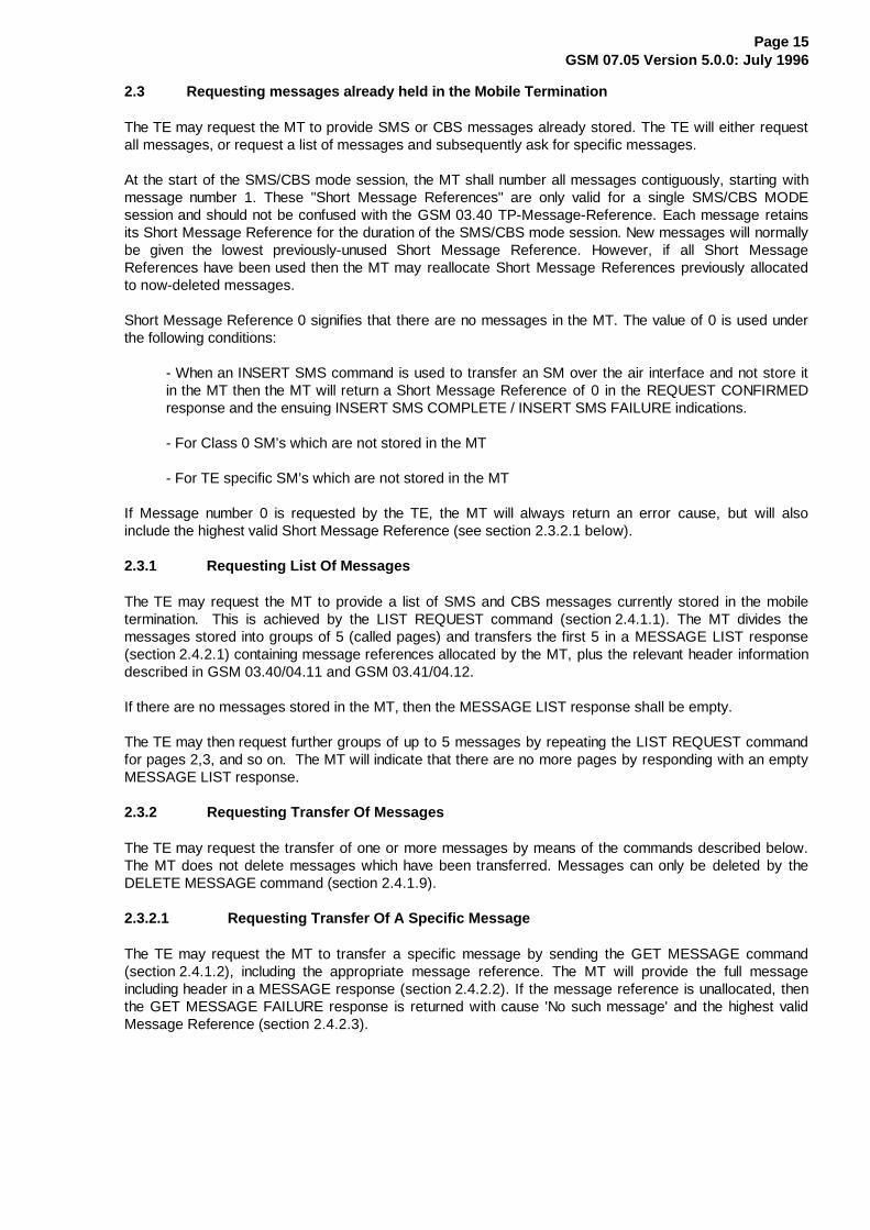
2.3 Requesting messages already held in the Mobile Termination
The TE may request the MT to provide SMS or CBS messages already stored. The TE will either requestall messages, or request a list of messages and subsequently ask for specific messages.
At the start of the SMS/CBS mode session, the MT shall number all messages contiguously, starting withmessage number 1. These "Short Message References" are only valid for a single SMS/CBS MODEsession and should not be confused with the GSM 03.40 TP-Message-Reference. Each message retainsits Short Message Reference for the duration of the SMS/CBS mode session. New messages will normallybe given the lowest previously-unused Short Message Reference. However, if all Short MessageReferences have been used then the MT may reallocate Short Message References previously allocatedto now-deleted messages.
Short Message Reference 0 signifies that there are no messages in the MT. The value of 0 is used underthe following conditions:
- When an INSERT SMS command is used to transfer an SM over the air interface and not store itin the MT then the MT will return a Short Message Reference of 0 in the REQUEST CONFIRMEDresponse and the ensuing INSERT SMS COMPLETE / INSERT SMS FAILURE indications.
- For Class 0 SM’s which are not stored in the MT
- For TE specific SM’s which are not stored in the MT
If Message number 0 is requested by the TE, the MT will always return an error cause, but will alsoinclude the highest valid Short Message Reference (see section 2.3.2.1 below).
2.3.1 Requesting List Of Messages
The TE may request the MT to provide a list of SMS and CBS messages currently stored in the mobiletermination. This is achieved by the LIST REQUEST command (section 2.4.1.1). The MT divides themessages stored into groups of 5 (called pages) and transfers the first 5 in a MESSAGE LIST response(section 2.4.2.1) containing message references allocated by the MT, plus the relevant header informationdescribed in GSM 03.40/04.11 and GSM 03.41/04.12.
If there are no messages stored in the MT, then the MESSAGE LIST response shall be empty.
The TE may then request further groups of up to 5 messages by repeating the LIST REQUEST commandfor pages 2,3, and so on. The MT will indicate that there are no more pages by responding with an emptyMESSAGE LIST response.
2.3.2 Requesting Transfer Of Messages
The TE may request the transfer of one or more messages by means of the commands described below.The MT does not delete messages which have been transferred. Messages can only be deleted by theDELETE MESSAGE command (section 2.4.1.9).
2.3.2.1 Requesting Transfer Of A Specific Message
The TE may request the MT to transfer a specific message by sending the GET MESSAGE command(section 2.4.1.2), including the appropriate message reference. The MT will provide the full messageincluding header in a MESSAGE response (section 2.4.2.2). If the message reference is unallocated, thenthe GET MESSAGE FAILURE response is returned with cause 'No such message' and the highest validMessage Reference (section 2.4.2.3).
Page 16GSM 07.05 Version 5.0.0: July 1996
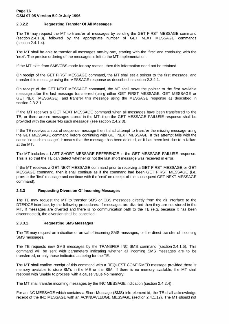
2.3.2.2 Requesting Transfer Of All Messages
The TE may request the MT to transfer all messages by sending the GET FIRST MESSAGE command(section 2.4.1.3), followed by the appropriate number of GET NEXT MESSAGE commands(section 2.4.1.4).
The MT shall be able to transfer all messages one-by-one, starting with the 'first' and continuing with the'next'. The precise ordering of the messages is left to the MT implementation.
If the MT exits from SMS/CBS mode for any reason, then this information need not be retained.
On receipt of the GET FIRST MESSAGE command, the MT shall set a pointer to the first message, andtransfer this message using the MESSAGE response as described in section 2.3.2.1.
On receipt of the GET NEXT MESSAGE command, the MT shall move the pointer to the first availablemessage after the last message transferred (using either GET FIRST MESSAGE, GET MESSAGE orGET NEXT MESSAGE), and transfer this message using the MESSAGE response as described insection 2.3.2.1.
If the MT receives a GET NEXT MESSAGE command when all messages have been transferred to theTE, or there are no messages stored in the MT, then the GET MESSAGE FAILURE response shall beprovided with the cause 'No such message' (see section 2.4.2.3).
If the TE receives an out of sequence message then it shall attempt to transfer the missing message usingthe GET MESSAGE command before continuing with GET NEXT MESSAGE. If this attempt fails with thecause 'no such message', it means that the message has been deleted, or it has been lost due to a failureat the MT.
The MT includes a LAST SHORT MESSAGE REFERENCE in the GET MESSAGE FAILURE response.This is so that the TE can detect whether or not the last short message was received in error.
If the MT receives a GET NEXT MESSAGE command prior to receiving a GET FIRST MESSAGE or GETMESSAGE command, then it shall continue as if the command had been GET FIRST MESSAGE (i.e.provide the 'first' message and continue with the 'next' on receipt of the subsequent GET NEXT MESSAGEcommand).
2.3.3 Requesting Diversion Of Incoming Messages
The TE may request the MT to transfer SMS or CBS messages directly from the air interface to theDTE/DCE interface, by the following procedures. If messages are diverted then they are not stored in theMT. If messages are diverted and there is no communication path to the TE (e.g. because it has beendisconnected), the diversion shall be cancelled.
2.3.3.1 Requesting SMS Messages
The TE may request an indication of arrival of incoming SMS messages, or the direct transfer of incomingSMS messages.
The TE requests new SMS messages by the TRANSFER INC SMS command (section 2.4.1.5). Thiscommand will be sent with parameters indicating whether all incoming SMS messages are to betransferred, or only those indicated as being for the TE.
The MT shall confirm receipt of this command with a REQUEST CONFIRMED message provided there ismemory available to store SM's in the ME or the SIM. If there is no memory available, the MT shallrespond with 'unable to process' with a cause value No memory.
The MT shall transfer incoming messages by the INC MESSAGE indication (section 2.4.2.4).
For an INC MESSAGE which contains a Short Message (SMS) info element id, the TE shall acknowledgereceipt of the INC MESSAGE with an ACKNOWLEDGE MESSAGE (section 2.4.1.12). The MT should not
Page 17GSM 07.05 Version 5.0.0: July 1996
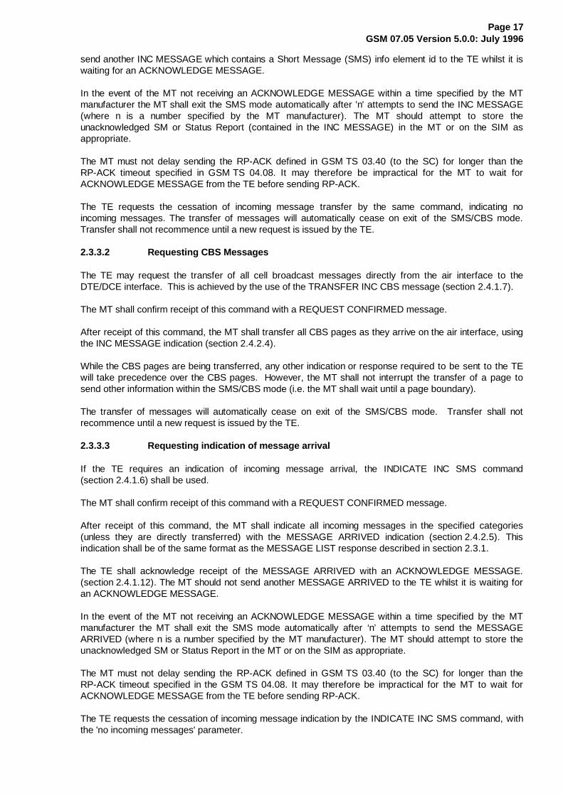
send another INC MESSAGE which contains a Short Message (SMS) info element id to the TE whilst it iswaiting for an ACKNOWLEDGE MESSAGE.
In the event of the MT not receiving an ACKNOWLEDGE MESSAGE within a time specified by the MTmanufacturer the MT shall exit the SMS mode automatically after 'n' attempts to send the INC MESSAGE(where n is a number specified by the MT manufacturer). The MT should attempt to store theunacknowledged SM or Status Report (contained in the INC MESSAGE) in the MT or on the SIM asappropriate.
The MT must not delay sending the RP-ACK defined in GSM TS 03.40 (to the SC) for longer than theRP-ACK timeout specified in GSM TS 04.08. It may therefore be impractical for the MT to wait forACKNOWLEDGE MESSAGE from the TE before sending RP-ACK.
The TE requests the cessation of incoming message transfer by the same command, indicating noincoming messages. The transfer of messages will automatically cease on exit of the SMS/CBS mode.Transfer shall not recommence until a new request is issued by the TE.
2.3.3.2 Requesting CBS Messages
The TE may request the transfer of all cell broadcast messages directly from the air interface to theDTE/DCE interface. This is achieved by the use of the TRANSFER INC CBS message (section 2.4.1.7).
The MT shall confirm receipt of this command with a REQUEST CONFIRMED message.
After receipt of this command, the MT shall transfer all CBS pages as they arrive on the air interface, usingthe INC MESSAGE indication (section 2.4.2.4).
While the CBS pages are being transferred, any other indication or response required to be sent to the TEwill take precedence over the CBS pages. However, the MT shall not interrupt the transfer of a page tosend other information within the SMS/CBS mode (i.e. the MT shall wait until a page boundary).
The transfer of messages will automatically cease on exit of the SMS/CBS mode. Transfer shall notrecommence until a new request is issued by the TE.
2.3.3.3 Requesting indication of message arrival
If the TE requires an indication of incoming message arrival, the INDICATE INC SMS command(section 2.4.1.6) shall be used.
The MT shall confirm receipt of this command with a REQUEST CONFIRMED message.
After receipt of this command, the MT shall indicate all incoming messages in the specified categories(unless they are directly transferred) with the MESSAGE ARRIVED indication (section 2.4.2.5). Thisindication shall be of the same format as the MESSAGE LIST response described in section 2.3.1.
The TE shall acknowledge receipt of the MESSAGE ARRIVED with an ACKNOWLEDGE MESSAGE.(section 2.4.1.12). The MT should not send another MESSAGE ARRIVED to the TE whilst it is waiting foran ACKNOWLEDGE MESSAGE.
In the event of the MT not receiving an ACKNOWLEDGE MESSAGE within a time specified by the MTmanufacturer the MT shall exit the SMS mode automatically after ‘n’ attempts to send the MESSAGEARRIVED (where n is a number specified by the MT manufacturer). The MT should attempt to store theunacknowledged SM or Status Report in the MT or on the SIM as appropriate.
The MT must not delay sending the RP-ACK defined in GSM TS 03.40 (to the SC) for longer than theRP-ACK timeout specified in the GSM TS 04.08. It may therefore be impractical for the MT to wait forACKNOWLEDGE MESSAGE from the TE before sending RP-ACK.
The TE requests the cessation of incoming message indication by the INDICATE INC SMS command, withthe 'no incoming messages' parameter.

Page 18GSM 07.05 Version 5.0.0: July 1996
2.3.4 Requesting Transfer Into Mobile Termination
The TE may request transfer of SMS messages into the mobile termination. Cell broadcast messagescannot be transferred in this direction.
The TE shall use the INSERT SMS command (section 2.4.1.8) to transfer the message. This commandshall indicate whether the message is to be stored in the MT, sent over the air interface or both. Thecommand shall include the full SMS message and header as described in GSM 03.40, except for themessage reference and message type indication (which are allocated by the MT).
Only one INSERT SMS command may be outstanding at any given instant. An INSERT SMS is deemedcomplete when an INSERT SMS COMPLETE or an INSERT SMS FAILURE indication has been receivedirrespective of whether an intermediate REQUEST CONFIRMED has been received.
Upon receipt of an INSERT SMS command, the MT shall act in the following way:
If the TE requested the MT to store the message, the MT shall attempt to store the message. If theattempt is successful, the MT shall return an INSERT SMS COMPLETE indication (section 2.4.2.6),including the message reference allocated by the MT. If the attempt fails (e.g. due to lack of memory), theMT shall return an INSERT SMS FAILURE indication (section 2.4.2.7), providing a cause for the failure.
If the TE requested the MT to send the message, the MT shall respond immediately with a REQUESTCONFIRMED message, and attempt to send the message. If the send attempt subsequently succeeds,the MT shall send an INSERT SMS COMPLETE indication, including the message references allocated bythe MT. If the send attempt subsequently fails, the MT shall return an INSERT SMS FAILURE indication,providing a cause for the failure.
If the TE requested the MT to store and send the message, the MT shall first attempt to store themessage. If no storage is available, the MT shall return an INSERT SMS FAILURE indication(section 2.4.2.7) and shall not attempt to send the message. If storage is available, the MT shall store themessage and then respond with a REQUEST CONFIRMED message. If the send attempt is successful,the MT shall return an INSERT SMS COMPLETE indication (section 2.4.2.6), including the messagereferences allocated by the MT. If the transmission of the message fails, then the MT shall return anINSERT SMS FAILURE indication (section 2.4.2.7). This will show that the send attempt failed and providea cause. After that the MT shall delete the stored message.
2.3.5 Requesting Deletion Of Messages
The TE may request deletion of SMS or CBS messages from the store in the MT. This is achieved by theDELETE MESSAGE command (section 2.4.1.9). The command will include a message reference, asdefined by the MT and provided in the message list.
Upon receipt of this command, the MT shall attempt to delete the message. If successful, the MT shallreturn a DELETE MESSAGE COMPLETE indication (section 2.4.2.8). If not successful, the MT shallreturn a DELETE MESSAGE FAILURE indication (section 2.4.2.9).
On successful deletion of an SM or CBS message the Page Index (see 2.5.2.10) and the Index Count (see2.5.2.8) shall be re-assigned so that their values are contiguous (i.e. there are no gaps in eitherparameter). The original short message Reference values remain unchanged.

Page 19GSM 07.05 Version 5.0.0: July 1996
2.4 Message functional definitions and contents
This section provides an overview of the message structure to be used over the DTE/DCE interface inSMS/CBS block mode. Each message definition includes a brief description of the use of the message,and a table showing all the information elements which may be included in the message. For eachinformation element the following data are provided:
Reference - this indicates where the detailed description of each element can be found.
Presence:
M Mandatory must always be presentreceiver: If not present, consider message erroneous
C Conditional presence depending on e.g.a) value of other elementb) presence of optional elementreceiver: If not present when condition met, consider messageerroneous
O Optional presence is a choice of the senderreceiver: present or not, accept message
Format:
T Type only, fixed length, only IEIV Value only, fixed length, no IEI includedTV Type and value, fixed length, IEI includedLV Length and value, variable length, no IEI included and Length indicator includedTLV Type, Length and Value, variable length, IEI and length indicator included
Length - this indicates the length of the information element in octets.
2.4.1 Commands Issued By The Terminal Equipment
Table 2.4.1/GSM 07.05 summarizes the commands which may be issued by the TE.
Table 2.4.1/GSM 07.05: Commands which may be issued by the TE
Reference
LIST REQUEST 2.4.1.1GET MESSAGE 2.4.1.2GET FIRST MESSAGE 2.4.1.3GET NEXT MESSAGE 2.4.1.4TRANSFER INC SMS 2.4.1.5INDICATE INC SMS 2.4.1.6TRANSFER INC CBS 2.4.1.7INSERT SMS 2.4.1.8DELETE MESSAGE 2.4.1.9UNABLE TO PROCESS 2.4.1.10END SMS MODE 2.4.1.11ACKNOWLEDGE MESSAGE 2.4.1.12

Page 20GSM 07.05 Version 5.0.0: July 1996
2.4.1.1 List Request
This message is sent by the TE to the MT to request a list of messages stored in the MT.
Information element Reference Presence Format Length
Message Type 2.5.1 M V 1
Page Index 2.5.2.10 M V 1
2.4.1.2 Get Message
This message is sent by the TE to the MT to request transfer of a specific SMS or CBS message stored inthe MT.
Information element Reference Presence Format Length
Message Type 2.5.1 M V 1
Short Message Reference 2.5.2.1 M V 1
2.4.1.3 Get First Message
This message is sent by the TE to the MT to request transfer of the first available SMS or CBS messagestored in the MT.
Information element Reference Presence Format Length
Message Type 2.5.1 M V 1
2.4.1.4 Get Next Message
This message is sent by the TE to the MT to request transfer of the next available SMS or CBS messagestored in the MT.
Information element Reference Presence Format Length
Message Type 2.5.1 M V 1
2.4.1.5 Transfer Inc SMS
This message is sent by the TE to the MT to request the direct transfer of incoming messages from the airinterface to the TE.
Information element Reference Presence Format Length
Message Type 2.5.1 M V 1
SMS Transfer Type 2.5.2.2 M V 1

Page 21GSM 07.05 Version 5.0.0: July 1996
2.4.1.6 Indicate Inc SMS
This message is sent by the TE to the MT to request that the MT indicates when an incoming messagearrives.
Information element Reference Presence Format Length
Message Type 2.5.1 M V 1
Indication Type 2.5.2.3 M V 1
2.4.1.7 Transfer Inc CBS
This message is sent by the TE to the MT to request transfer of all cell broadcast messages directly fromthe air interface to the DTE/DCE interface.
Information element Reference Presence Format Length
Message Type 2.5.1 M V 1
CBS Transfer Type 2.5.2.9 M V 1
2.4.1.8 Insert SMS
This message is sent by the TE to the MT to request the transfer of an SMS TPU to the MT memory oracross the air interface. The TPDU is formatted in exactly the same way as described in TS 03.40. Wherethe TPDU includes a TP-Message-Reference which is to be incremented by the MT for every outgoingmessage, the TP-Message-Reference provided by the TE will be overwritten by the MT beforetransmission of the message. The value provided by the TE is discarded by the MT and has nosignificance.
Information element Reference Presence Format Length
Message Type 2.5.1 M V 1
Insert Type 2.5.2.4 M V 1
RP-Destination-Address GSM 04.11 M LV 1-12 a)
SMS-TPDU GSM 03.40 M V max 164
a) If no RP-Destination-Address is to be transferred then the length is set to 0. In this case, the MTinserts the default SC address.
Page 22GSM 07.05 Version 5.0.0: July 1996
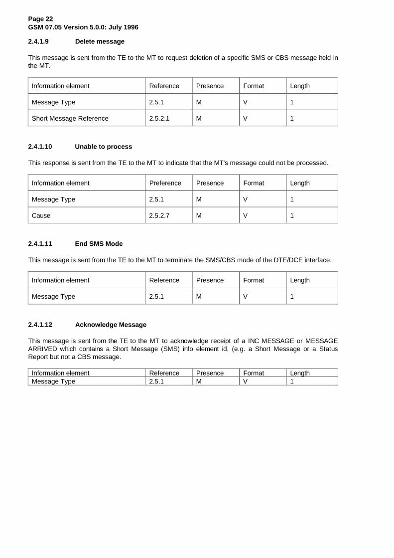
2.4.1.9 Delete message
This message is sent from the TE to the MT to request deletion of a specific SMS or CBS message held inthe MT.
Information element Reference Presence Format Length
Message Type 2.5.1 M V 1
Short Message Reference 2.5.2.1 M V 1
2.4.1.10 Unable to process
This response is sent from the TE to the MT to indicate that the MT's message could not be processed.
Information element Preference Presence Format Length
Message Type 2.5.1 M V 1
Cause 2.5.2.7 M V 1
2.4.1.11 End SMS Mode
This message is sent from the TE to the MT to terminate the SMS/CBS mode of the DTE/DCE interface.
Information element Reference Presence Format Length
Message Type 2.5.1 M V 1
2.4.1.12 Acknowledge Message
This message is sent from the TE to the MT to acknowledge receipt of a INC MESSAGE or MESSAGEARRIVED which contains a Short Message (SMS) info element id, (e.g. a Short Message or a StatusReport but not a CBS message.
Information element Reference Presence Format LengthMessage Type 2.5.1 M V 1

Page 23GSM 07.05 Version 5.0.0: July 1996
2.4.2 Responses/Indications Issued By The MT
Table 2.4.2/GSM 07.05 summarizes the responses/indications which may be issued by the MT.
Table 2.4.2/GSM 07.05: Responses/Indications which may be issued by the MT
ReferenceMESSAGE LIST 2.4.2.1MESSAGE 2.4.2.2GET MESSAGE FAILURE 2.4.2.3INC MESSAGE 2.4.2.4MESSAGE ARRIVED 2.4.2.5INSERT SMS COMPLETE 2.4.2.6INSERT SMS FAILURE 2.4.2.7DELETE MESSAGE COMPLETE 2.4.2.8DELETE MESSAGE FAILURE 2.4.2.9UNABLE TO PROCESS 2.4.2.10END SMS MODE 2.4.2.11REQUEST CONFIRMED 2.4.2.12
Page 24GSM 07.05 Version 5.0.0: July 1996
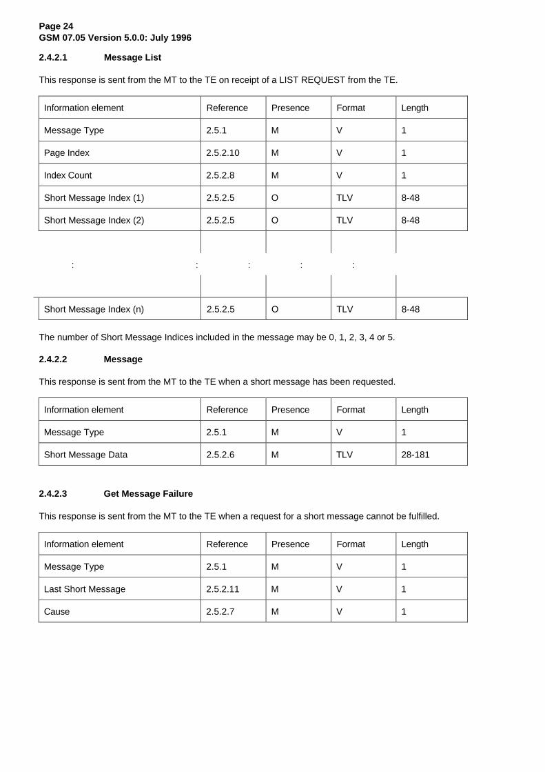
2.4.2.1 Message List
This response is sent from the MT to the TE on receipt of a LIST REQUEST from the TE.
Information element Reference Presence Format Length
Message Type 2.5.1 M V 1
Page Index 2.5.2.10 M V 1
Index Count 2.5.2.8 M V 1
Short Message Index (1) 2.5.2.5 O TLV 8-48
Short Message Index (2) 2.5.2.5 O TLV 8-48
: : : : :
Short Message Index (n) 2.5.2.5 O TLV 8-48
The number of Short Message Indices included in the message may be 0, 1, 2, 3, 4 or 5.
2.4.2.2 Message
This response is sent from the MT to the TE when a short message has been requested.
Information element Reference Presence Format Length
Message Type 2.5.1 M V 1
Short Message Data 2.5.2.6 M TLV 28-181
2.4.2.3 Get Message Failure
This response is sent from the MT to the TE when a request for a short message cannot be fulfilled.
Information element Reference Presence Format Length
Message Type 2.5.1 M V 1
Last Short Message 2.5.2.11 M V 1
Cause 2.5.2.7 M V 1

Page 25GSM 07.05 Version 5.0.0: July 1996
2.4.2.4 Inc Message
This indication is sent from the MT to the TE after the MT has been requested to transfer messages ofcertain categories immediately upon receipt.
Information element Reference Presence Format Length
Message Type 2.5.1 M V 1
Short Message Data 2.5.2.6 M TLV 28-181
2.4.2.5 Message Arrived
This indication is sent from the MT to the TE after the MT has been requested to provide an indication ofthe receipt of certain categories of incoming message.
Information element Reference Presence Format Length
Message Type 2.5.1 M V 1
Short Message Index 2.5.2.5 M TLV 8-48
2.4.2.6 Insert SMS Complete
This response is sent by the MT to the TE to indicate that the TE's request to insert a message has beencompleted.
Information element Reference Presence Format Length
Message Type 2.5.1 M V 1
Short Message Reference 2.5.2.1 M V 1
TP-Message Reference GSM 03.40 C a) V 1
a) The TP-Message Reference is only included if the message had been requested to be transferredover the air interface.
2.4.2.7 Insert SMS Failure
This response is sent from the MT to the TE to indicate that the attempt to insert an SMS message failed.
Information element Reference Presence Format Length
Message Type 2.5.1 M V 1
Cause 2.5.2.7 M V 1-2
TP-Failure Cause 2.5.2.13 O TLV 4
Short Message Reference 2.5.2.1 O TV 2

Page 26GSM 07.05 Version 5.0.0: July 1996
2.4.2.8 Delete Message Complete
This response is sent from the MT to the TE to indicate that the request to delete a message from the MTstore has been completed.
Information element Reference Presence Format Length
Message Type 2.5.1 M V 1
Short Message Reference 2.5.2.1 M V 1
2.4.2.9 Delete Message Failure
This response is sent from the MT to the TE to indicate that the request to delete a message from the MTstore failed.
Information element Reference Presence Format Length
Message Type 2.5.1 M V 1
Short Message Reference 2.5.2.1 M V 1
Cause 2.5.2.7 M V 1
2.4.2.10 Unable To Process
This response is sent from the MT to the TE to indicate that the TE's request could not be processed.
Information element Reference Presence Format Length
Message Type 2.5.1 M V 1
Cause 2.5.2.7 M V 1
2.4.2.11 End SMS Mode
This indication is sent from the MT to the TE when the MT autonomously exits from SMS/CBS mode.
Information element Reference Presence Format Length
Message Type 2.5.1 M V 1
Cause 2.5.2.7 M V 1
Page 27GSM 07.05 Version 5.0.0: July 1996
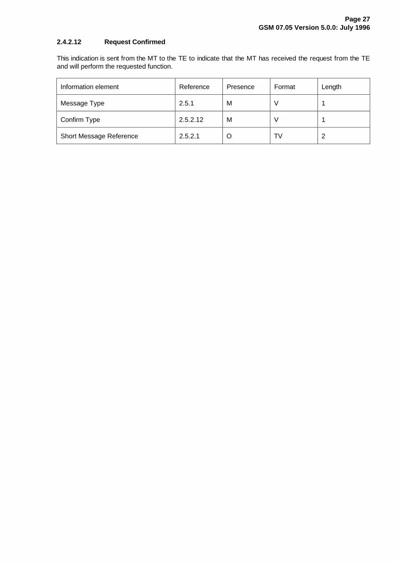
2.4.2.12 Request Confirmed
This indication is sent from the MT to the TE to indicate that the MT has received the request from the TEand will perform the requested function.
Information element Reference Presence Format Length
Message Type 2.5.1 M V 1
Confirm Type 2.5.2.12 M V 1
Short Message Reference 2.5.2.1 O TV 2

Page 28GSM 07.05 Version 5.0.0: July 1996
2.5 General message format and information elements coding
This section describes the content of messages for the SMS/CBS mode of the DTE/DCE interface. Withinthe figures in this section, the bit designated "bit 1" is transmitted first, followed by bits 2,3,4 etc. Similarly,the octet shown at the top of each figure is sent first.
2.5.1 Message Type
The purpose of the message type is to identify the function of the message being sent. The message typeis coded as shown in figure 2.5.1/GSM 07.05 and table 2.5.1/GSM 07.05.
Bit 8 is reserved for possible future use as an extension bit.
� � � � � � � �¸¶¶¶¶¶¾¶¶¶¶¶¶¶¶¶¶¶¶¶¶¶¶¶¶¶¶¶¶¶¶¶¶¶¶¶¶¶¶¶¶¶¶¶¶¶¶¶¹·�����·����������0HVVDJH�7\SH�������������������· RFWHW��¼¶¶¶¶¶À¶¶¶¶¶¶¶¶¶¶¶¶¶¶¶¶¶¶¶¶¶¶¶¶¶¶¶¶¶¶¶¶¶¶¶¶¶¶¶¶¶½
Figure 2.5.1/GSM 07.05: Message Type
Table 2.5.1/GSM 07.05: Message Types
8 7 6 5 4 3 2 1
0 0 0 - - - - - Commands/ Responses issued by TE
0 0 0 0 0 0 0 0 LIST REQUEST0 0 0 0 0 0 0 1 GET MESSAGE0 0 0 0 0 0 1 0 GET FIRST MESSAGE0 0 0 0 0 0 1 1 GET NEXT MESSAGE0 0 0 0 0 1 0 0 TRANSFER INC SMS0 0 0 0 0 1 0 1 INDICATE INC SMS0 0 0 0 0 1 1 0 TRANSFER INC CBS0 0 0 0 0 1 1 1 INSERT SMS0 0 0 0 1 0 0 0 DELETE MESSAGE0 0 0 0 1 0 0 1 UNABLE TO PROCESS0 0 0 1 1 1 1 0 END SMS MODE0 0 0 1 1 1 1 1 ACKNOWLEDGE MESSAGE
0 0 1 - - - - - Responses/Indications issued by MT
0 0 1 0 0 0 0 0 MESSAGE LIST0 0 1 0 0 0 0 1 MESSAGE0 0 1 0 0 0 1 0 GET MESSAGE FAILURE0 0 1 0 0 0 1 1 INC MESSAGE0 0 1 0 0 1 0 0 MESSAGE ARRIVED0 0 1 0 0 1 0 1 INSERT SMS COMPLETE0 0 1 0 0 1 1 0 INSERT SMS FAILURE0 0 1 0 0 1 1 1 DELETE MESSAGE COMPLETE0 0 1 0 1 0 0 0 DELETE MESSAGE FAILURE0 0 1 0 1 0 0 1 UNABLE TO PROCESS0 0 1 0 1 0 1 0 REQUEST CONFIRMED0 0 1 1 1 1 1 1 END SMS MODE
All other values are reserved
Page 29GSM 07.05 Version 5.0.0: July 1996
2.5.2 Other Information Elements
Other information elements follow the general coding principles specified in GSM 04.08, and are describedin the following sections.
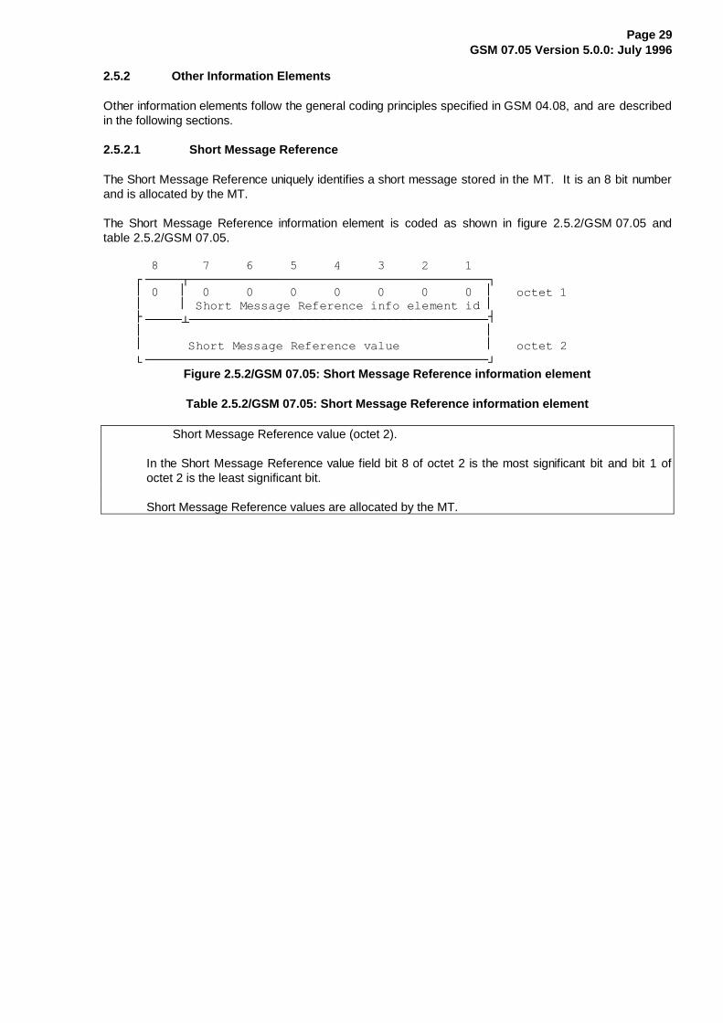
2.5.2.1 Short Message Reference
The Short Message Reference uniquely identifies a short message stored in the MT. It is an 8 bit numberand is allocated by the MT.
The Short Message Reference information element is coded as shown in figure 2.5.2/GSM 07.05 andtable 2.5.2/GSM 07.05.
����������������������������������������������¸¶¶¶¶¶¾¶¶¶¶¶¶¶¶¶¶¶¶¶¶¶¶¶¶¶¶¶¶¶¶¶¶¶¶¶¶¶¶¶¶¶¶¶¶¶¶¶¹·�����·�����������������������������������������·���RFWHW��·�����·�6KRUW�0HVVDJH�5HIHUHQFH�LQIR�HOHPHQW�LG�·¼¶¶¶¶¶¿¶¶¶¶¶¶¶¶¶¶¶¶¶¶¶¶¶¶¶¶¶¶¶¶¶¶¶¶¶¶¶¶¶¶¶¶¶¶¶¶¶½·�����������������������������������������������··������6KRUW�0HVVDJH�5HIHUHQFH�YDOXH������������·���RFWHW��º¶¶¶¶¶¶¶¶¶¶¶¶¶¶¶¶¶¶¶¶¶¶¶¶¶¶¶¶¶¶¶¶¶¶¶¶¶¶¶¶¶¶¶¶¶¶¶»
Figure 2.5.2/GSM 07.05: Short Message Reference information element
Table 2.5.2/GSM 07.05: Short Message Reference information element
Short Message Reference value (octet 2).
In the Short Message Reference value field bit 8 of octet 2 is the most significant bit and bit 1 ofoctet 2 is the least significant bit.
Short Message Reference values are allocated by the MT.

Page 30GSM 07.05 Version 5.0.0: July 1996
2.5.2.2 SMS Transfer Type
The SMS Transfer Type indicates to the MT which SMS messages are required to be transferred to theTE.
The SMS Transfer Type information element is coded as shown in figure 2.5.3/GSM 07.05 and table2.5.3/GSM 07.05.
����������������������������������������������¸¶¶¶¶¶¾¶¶¶¶¶¶¶¶¶¶¶¶¶¶¶¶¶¶¶¶¶¶¶¶¶¶¶¶¶¶¶¶¶¶¶¶¶¶¶¶¶¹·�����·�����������������������������������������·���RFWHW��·�����·�606�7UDQVIHU�7\SH�LQIR�HOHPHQW�LGHQW����·¼¶¶¶¶¶¿¶¶¶¶¶¶¶¶¶¶¶¶¶¶¶¶¶¶¶¶¶¶¶¾¶¶¶¶¶¶¶¶¶¶¶¶¶¶¶¶¶½·�����������������������������·��606�7[IU�������··����������5HVHUYHG�����������·�7\SH�YDOXH������·���RFWHW��º¶¶¶¶¶¶¶¶¶¶¶¶¶¶¶¶¶¶¶¶¶¶¶¶¶¶¶¶¶¿¶¶¶¶¶¶¶¶¶¶¶¶¶¶¶¶¶»
Figure 2.5.3/GSM 07.05: SMS Transfer Type information element
Table 2.5.3/GSM 07.05: SMS Transfer Type information element
SMS Txfr Type value (octet 2).
The SMS txfr type is coded as follows:
bit 2 bit 10 0 Transfer no SMS messages0 1 Transfer SMS messages marked as
TE-specific1 0 Reserved1 1 Transfer all SMS messages
Bit 3 shows whether to transfer SMS-STATUS-REPORTS
Bit 30 Do not transfer SMS-STATUS-REPORTS1 Transfer SMS-STATUS-REPORTS

Page 31GSM 07.05 Version 5.0.0: July 1996
2.5.2.3 Indication Type
The Indication Type tells the MT when to notify the TE that an incoming message has been received.
The Indication Type information element is coded as shown in figure 2.5.4/GSM 07.05 andtable 2.5.4/GSM 07.05.
����������������������������������������������¸¶¶¶¶¶¾¶¶¶¶¶¶¶¶¶¶¶¶¶¶¶¶¶¶¶¶¶¶¶¶¶¶¶¶¶¶¶¶¶¶¶¶¶¶¶¶¶¹
�������·�����·�����������������������������������������·RFWHW��·�����·,QGLFDWLRQ�7\SH�LQIR�HOHPHQW�LGHQWLILHU��·¼¶¶¶¶¶¿¶¶¶¶¶¶¶¶¶¶¶¶¶¶¶¶¶¾¶¶¶¶¶¶¶¶¶¶¶¶¶¶¶¶¶¶¶¶¶¶¶½·�����������������������·��,QGLFDWLRQ�7\SH������·
�������·�������5HVHUYHG��������·�������YDOXH�����������·RFWHW��º¶¶¶¶¶¶¶¶¶¶¶¶¶¶¶¶¶¶¶¶¶¶¶¿¶¶¶¶¶¶¶¶¶¶¶¶¶¶¶¶¶¶¶¶¶¶¶»Figure 2.5.4/GSM 07.05: Indication Type information element
Table 2.5.4/GSM 07.05: Indication Type information element
Indication Type value (octet 2).
The indication type is coded as follows:
bit 3 bit 2 bit 10 0 0 Indicate no messages0 0 1 Reserved0 1 0 Indicate all SMS messages0 1 1 Indicate SMS messages marked as
TE-specific1 0 0 Indicate all CBS messages1 0 1 Indicate CBS messages marked as
TE-specific1 1 0 Indicate all CBS and SMS messages1 1 1 Indicate SMS and CBS messages marked
as TE-specific
Bit 4 shows whether or not to indicate SMS reports:
bit 40 Do not indicate SMS reports1 Indicate SMS reports

Page 32GSM 07.05 Version 5.0.0: July 1996
2.5.2.4 Insert Type
The Insert Type tells the MT what to do with the short message arriving from the TE.
The Insert Type information element is coded as shown in figure 2.5.5/GSM 07.05 and table 2.5.5/GSM 07.05
���������������������������������������������¸¶¶¶¶¶¾¶¶¶¶¶¶¶¶¶¶¶¶¶¶¶¶¶¶¶¶¶¶¶¶¶¶¶¶¶¶¶¶¶¶¶¶¶¶¶¶¶¹·�����·�����������������������������������������·���RFWHW��·�����·�,QVHUW�7\SH�LQIR�HOHPHQW�LGHQWLILHU�����·¼¶¶¶¶¶¿¶¶¶¶¶¶¶¶¶¶¶¶¶¶¶¶¶¶¶¶¶¶¶¶¶¶¶¶¶¾¶¶¶¶¶¶¶¶¶¶¶½·�����������������������������������·���,QVHUW��··������������5HVHUYHG���������������·�7\SH�YDOXH·���RFWHW��º¶¶¶¶¶¶¶¶¶¶¶¶¶¶¶¶¶¶¶¶¶¶¶¶¶¶¶¶¶¶¶¶¶¶¶¿¶¶¶¶¶¶¶¶¶¶¶»
Figure 2.5.5/GSM 07.05: Insert Type information element
Table 2.5.5/GSM 07.05: Insert Type information element
Insert Type value (octet 2).
The insert type is coded as follows:
bit 2 bit 10 0 Reserved0 1 Store the short message in the MT1 0 Send the short message over the air1 1 Store the short message in the MT and send it over the air

Page 33GSM 07.05 Version 5.0.0: July 1996
2.5.2.5 Short Message Index
The Short Message Index provides information about each individual short message currently stored in theMT. Two types of Short Message index are provided; one for SMS and one for CBS.
The Short Message Index (SMS) information element is coded as shown in figure 2.5.6/GSM 07.05 andtable 2.5.6/GSM 07.05. A Short Message Index may be an SMS-SUBMIT, an SMS-DELIVER or anSMS-STATUS-REPORT.
The Short Message Index (CBS) information element is coded as shown in figure 2.5.7/GSM 07.05 andtable 2.5.7/GSM 07.05.
����������������������������������������������¸¶¶¶¶¶¾¶¶¶¶¶¶¶¶¶¶¶¶¶¶¶¶¶¶¶¶¶¶¶¶¶¶¶¶¶¶¶¶¶¶¶¶¶¶¶¶¶¹·�����·�����������������������������������������·��RFWHW��·�����·6KRUW�0HVVDJH�,QGH[��606��LQIR�HOHPHQW�LG·¼¶¶¶¶¶¿¶¶¶¶¶¶¶¶¶¶¶¶¶¶¶¶¶¶¶¶¶¶¶¶¶¶¶¶¶¶¶¶¶¶¶¶¶¶¶¶¶½·�����������������������������������������������··�������/HQJWK�RI�6KRUW�0HVVDJH�,QGH[�����������·��RFWHW��¼¶¶¶¶¶¶¶¶¶¶¶¶¶¶¶¶¶¶¶¶¶¶¶¶¶¶¶¶¶¶¶¶¶¶¶¶¶¶¶¶¶¶¶¶¶¶¶½·�����������������������������������������������··������6KRUW�0HVVDJH�5HIHUHQFH�YDOXH������������·��RFWHW��¼¶¶¶¶¶¶¶¶¶¶¶¶¶¶¶¶¶¶¶¶¶¶¶¶¶¶¶¶¶¶¶¶¶¶¶¶¶¶¶¶¶¶¶¶¶¶¶½·�����������������������������������������������··�����������6KRUW�0HVVDJH�6WDWXV����������������·��RFWHW��¼¶¶¶¶¶¶¶¶¶¶¶¶¶¶¶¶¶¶¶¶¶¶¶¶¶¶¶¶¶¶¶¶¶¶¶¶¶¶¶¶¶¶¶¶¶¶¶½·�����������������������������������������������·��RFWHWV·����������6HUYLFH�&HQWUH�$GGUHVV���������������·����Q¼¶¶¶¶¶¶¶¶¶¶¶¶¶¶¶¶¶¶¶¶¶¶¶¶¶¶¶¶¶¶¶¶¶¶¶¶¶¶¶¶¶¶¶¶¶¶¶½·�����������������������������������������������·��RFWHWV·�����������6KRUW�0HVVDJH�+HDGHU��606�����������·º¶¶¶¶¶¶¶¶¶¶¶¶¶¶¶¶¶¶¶¶¶¶¶¶¶¶¶¶¶¶¶¶¶¶¶¶¶¶¶¶¶¶¶¶¶¶¶»Q�����Q���
Figure 2.5.6/GSM 07.05: Short Message Index (SMS) information element
n can take a value between 5 and 18 (inclusive)
Page 34GSM 07.05 Version 5.0.0: July 1996
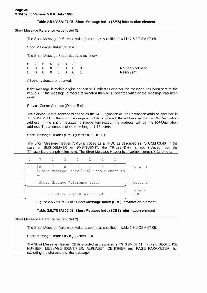
Table 2.5.6/GSM 07.05: Short Message Index (SMS) information element
Short Message Reference value (octet 3).
The Short Message Reference value is coded as specified in table 2.5.2/GSM 07.05.
Short Message Status (octet 4).
The Short Message Status is coded as follows:
8 7 6 5 4 3 2 10 0 0 0 0 0 0 0 Not read/not sent0 0 0 0 0 0 0 1 Read/Sent
All other values are reserved.
If the message is mobile originated then bit 1 indicates whether the message has been sent to thenetwork. If the message is mobile terminated then bit 1 indicates whether the message has beenread.
Service Centre Address (Octets 5-n).
The Service Centre Address is coded as the RP-Origination or RP-Destination address specified inTS GSM 04.11. If the short message is mobile originated, the address will be the RP-Destinationaddress. If the short message is mobile terminated, the address will be the RP-Originationaddress. The address is of variable length, 1-12 octets.
Short Message Header (SMS) (Octets n+1 - n+31).
The Short Message Header (SMS) is coded as a TPDU as described in TS GSM 03.40. In thecase of SMS-DELIVER or SMS-SUBMIT, the TP-User-Data is not included, but theTP-User-Data-Length is included. The Short Message Header is of variable length, 6-31 octets.
��������������������������������������������¸¶¶¶¶¶¾¶¶¶¶¶¶¶¶¶¶¶¶¶¶¶¶¶¶¶¶¶¶¶¶¶¶¶¶¶¶¶¶¶¶¶¶¶¶¶¶¶¹·�����·�����������������������������������������·���RFWHW��·�����·6KRUW�0HVVDJH�,QGH[��&%6��LQIR�HOHPHQW�LG·¼¶¶¶¶¶¿¶¶¶¶¶¶¶¶¶¶¶¶¶¶¶¶¶¶¶¶¶¶¶¶¶¶¶¶¶¶¶¶¶¶¶¶¶¶¶¶¶½·�����������������������������������������������··������6KRUW�0HVVDJH�5HIHUHQFH�YDOXH������������·���RFWHW��¼¶¶¶¶¶¶¶¶¶¶¶¶¶¶¶¶¶¶¶¶¶¶¶¶¶¶¶¶¶¶¶¶¶¶¶¶¶¶¶¶¶¶¶¶¶¶¶½·�����������������������������������������������·���RFWHWV·�����������6KRUW�0HVVDJH�+HDGHU��&%6�����������·������º¶¶¶¶¶¶¶¶¶¶¶¶¶¶¶¶¶¶¶¶¶¶¶¶¶¶¶¶¶¶¶¶¶¶¶¶¶¶¶¶¶¶¶¶¶¶¶»
Figure 2.5.7/GSM 07.05: Short Message Index (CBS) information element
Table 2.5.7/GSM 07.05: Short Message Index (CBS) information element
Short Message Reference value (octet 2).
The Short Message Reference value is coded as specified in table 2.5.2/GSM 07.05.
Short Message Header (CBS) (Octets 3-8).
The Short Message Header (CBS) is coded as described in TS GSM 03.41, including SEQUENCENUMBER, MESSAGE IDENTIFIER, ALPHABET IDENTIFIER and PAGE PARAMETER, butexcluding the characters of the message.

Page 35GSM 07.05 Version 5.0.0: July 1996
2.5.2.6 Short Message Data
The Short Message Data information element is a copy of a short message currently stored in the MT.Two types of Short Message Data information element are provided; one for SMS and one for CBS.
The Short Message Data (SMS) information element is coded as shown in figure 2.5.8/GSM 07.05 andtable 2.5.8/GSM 07.05. Short Message Data may be an SMS-SUBMIT, an SMS-DELIVER or anSMS-STATUS-REPORT.
The Short Message Data (CBS) information element is coded as shown in figure 2.5.9/GSM 07.05 andtable 2.5.9/GSM 07.05.
��������������������������������������������¸¶¶¶¶¶¾¶¶¶¶¶¶¶¶¶¶¶¶¶¶¶¶¶¶¶¶¶¶¶¶¶¶¶¶¶¶¶¶¶¶¶¶¶¶¶¶¶¹·�����·�����������������������������������������·�RFWHW��·�����·6KRUW�0HVVDJH�'DWD��606��LQIR�HOHPHQW�LG�·¼¶¶¶¶¶¿¶¶¶¶¶¶¶¶¶¶¶¶¶¶¶¶¶¶¶¶¶¶¶¶¶¶¶¶¶¶¶¶¶¶¶¶¶¶¶¶¶½·�����������������������������������������������··����������/HQJWK�RI�6KRUW�0HVVDJH�'DWD���������·�RFWHW��¼¶¶¶¶¶¶¶¶¶¶¶¶¶¶¶¶¶¶¶¶¶¶¶¶¶¶¶¶¶¶¶¶¶¶¶¶¶¶¶¶¶¶¶¶¶¶¶½·�����������������������������������������������··������6KRUW�0HVVDJH�5HIHUHQFH�YDOXH������������·�RFWHW��¼¶¶¶¶¶¶¶¶¶¶¶¶¶¶¶¶¶¶¶¶¶¶¶¶¶¶¶¶¶¶¶¶¶¶¶¶¶¶¶¶¶¶¶¶¶¶¶½·�����������������������������������������������··�����������6KRUW�0HVVDJH�6WDWXV����������������·�RFWHW��¼¶¶¶¶¶¶¶¶¶¶¶¶¶¶¶¶¶¶¶¶¶¶¶¶¶¶¶¶¶¶¶¶¶¶¶¶¶¶¶¶¶¶¶¶¶¶¶½·�����������������������������������������������·�RFWHWV·����������6HUYLFH�&HQWUH�$GGUHVV���������������·���Q¼¶¶¶¶¶¶¶¶¶¶¶¶¶¶¶¶¶¶¶¶¶¶¶¶¶¶¶¶¶¶¶¶¶¶¶¶¶¶¶¶¶¶¶¶¶¶¶½·�����������������������������������������������·�RFWHWV·�������������6KRUW�0HVVDJH��606����������������·º¶¶¶¶¶¶¶¶¶¶¶¶¶¶¶¶¶¶¶¶¶¶¶¶¶¶¶¶¶¶¶¶¶¶¶¶¶¶¶¶¶¶¶¶¶¶¶»Q���Q����
Figure 2.5.8/GSM 07.05: Short Message Data (SMS) information element
n can take a value between 5 and 18 (inclusive)
Page 36GSM 07.05 Version 5.0.0: July 1996
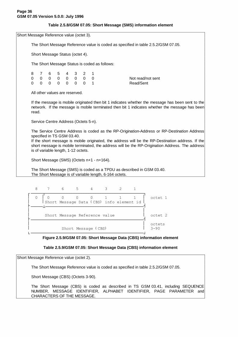
Table 2.5.8/GSM 07.05: Short Message (SMS) information el ement
Short Message Reference value (octet 3).
The Short Message Reference value is coded as specified in table 2.5.2/GSM 07.05.
Short Message Status (octet 4).
The Short Message Status is coded as follows:
8 7 6 5 4 3 2 10 0 0 0 0 0 0 0 Not read/not sent0 0 0 0 0 0 0 1 Read/Sent
All other values are reserved.
If the message is mobile originated then bit 1 indicates whether the message has been sent to thenetwork. If the message is mobile terminated then bit 1 indicates whether the message has beenread.
Service Centre Address (Octets 5-n).
The Service Centre Address is coded as the RP-Origination-Address or RP-Destination Addressspecified in TS GSM 03.40.If the short message is mobile originated, the address will be the RP-Destination address. If theshort message is mobile terminated, the address will be the RP-Origination Address. The addressis of variable length, 1-12 octets.
Short Message (SMS) (Octets n+1 - n+164).
The Short Message (SMS) is coded as a TPDU as described in GSM 03.40.The Short Message is of variable length, 6-164 octets.
���������������������������������������������¸¶¶¶¶¶¾¶¶¶¶¶¶¶¶¶¶¶¶¶¶¶¶¶¶¶¶¶¶¶¶¶¶¶¶¶¶¶¶¶¶¶¶¶¶¶¶¶¹·�����·�����������������������������������������·��RFWHW��·�����·6KRUW�0HVVDJH�'DWD��&%6��LQIR�HOHPHQW�LG�·¼¶¶¶¶¶¿¶¶¶¶¶¶¶¶¶¶¶¶¶¶¶¶¶¶¶¶¶¶¶¶¶¶¶¶¶¶¶¶¶¶¶¶¶¶¶¶¶½·�����������������������������������������������··������6KRUW�0HVVDJH�5HIHUHQFH�YDOXH������������·��RFWHW��¼¶¶¶¶¶¶¶¶¶¶¶¶¶¶¶¶¶¶¶¶¶¶¶¶¶¶¶¶¶¶¶¶¶¶¶¶¶¶¶¶¶¶¶¶¶¶¶½·�����������������������������������������������·��RFWHWV·�������������6KRUW�0HVVDJH��&%6����������������·������º¶¶¶¶¶¶¶¶¶¶¶¶¶¶¶¶¶¶¶¶¶¶¶¶¶¶¶¶¶¶¶¶¶¶¶¶¶¶¶¶¶¶¶¶¶¶¶»
Figure 2.5.9/GSM 07.05: Short Message Data (CBS) information element
Table 2.5.9/GSM 07.05: Short Message Data (CBS) information element
Short Message Reference value (octet 2).
The Short Message Reference value is coded as specified in table 2.5.2/GSM 07.05.
Short Message (CBS) (Octets 3-90).
The Short Message (CBS) is coded as described in TS GSM 03.41, including SEQUENCENUMBER, MESSAGE IDENTIFIER, ALPHABET IDENTIFIER, PAGE PARAMETER andCHARACTERS OF THE MESSAGE.
Page 37GSM 07.05 Version 5.0.0: July 1996
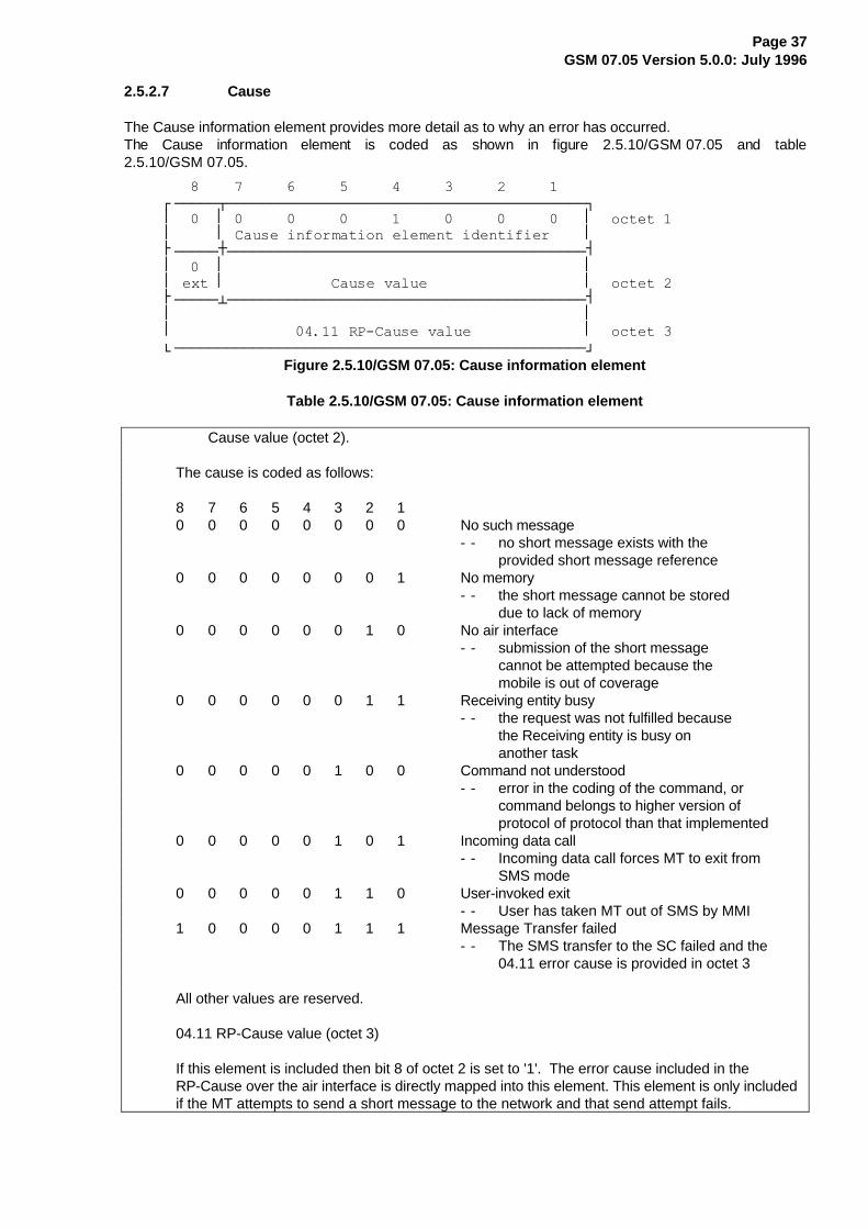
2.5.2.7 Cause
The Cause information element provides more detail as to why an error has occurred.The Cause information element is coded as shown in figure 2.5.10/GSM 07.05 and table2.5.10/GSM 07.05.
���������������������������������������������¸¶¶¶¶¶¾¶¶¶¶¶¶¶¶¶¶¶¶¶¶¶¶¶¶¶¶¶¶¶¶¶¶¶¶¶¶¶¶¶¶¶¶¶¶¶¶¶¹·�����·�����������������������������������������·��RFWHW��·�����·�&DXVH�LQIRUPDWLRQ�HOHPHQW�LGHQWLILHU����·¼¶¶¶¶¶À¶¶¶¶¶¶¶¶¶¶¶¶¶¶¶¶¶¶¶¶¶¶¶¶¶¶¶¶¶¶¶¶¶¶¶¶¶¶¶¶¶½·�����·�����������������������������������������··�H[W�·������������&DXVH�YDOXH������������������·��RFWHW��¼¶¶¶¶¶¿¶¶¶¶¶¶¶¶¶¶¶¶¶¶¶¶¶¶¶¶¶¶¶¶¶¶¶¶¶¶¶¶¶¶¶¶¶¶¶¶¶½·�����������������������������������������������··��������������������53�&DXVH�YDOXH�������������·��RFWHW��º¶¶¶¶¶¶¶¶¶¶¶¶¶¶¶¶¶¶¶¶¶¶¶¶¶¶¶¶¶¶¶¶¶¶¶¶¶¶¶¶¶¶¶¶¶¶¶»
Figure 2.5.10/GSM 07.05: Cause information element
Table 2.5.10/GSM 07.05: Cause information element
Cause value (octet 2).
The cause is coded as follows:
8 7 6 5 4 3 2 10 0 0 0 0 0 0 0 No such message
- - no short message exists with theprovided short message reference
0 0 0 0 0 0 0 1 No memory- - the short message cannot be stored
due to lack of memory0 0 0 0 0 0 1 0 No air interface
- - submission of the short messagecannot be attempted because themobile is out of coverage
0 0 0 0 0 0 1 1 Receiving entity busy- - the request was not fulfilled because
the Receiving entity is busy onanother task
0 0 0 0 0 1 0 0 Command not understood- - error in the coding of the command, or
command belongs to higher version ofprotocol of protocol than that implemented
0 0 0 0 0 1 0 1 Incoming data call- - Incoming data call forces MT to exit from
SMS mode0 0 0 0 0 1 1 0 User-invoked exit
- - User has taken MT out of SMS by MMI1 0 0 0 0 1 1 1 Message Transfer failed
- - The SMS transfer to the SC failed and the04.11 error cause is provided in octet 3
All other values are reserved.
04.11 RP-Cause value (octet 3)
If this element is included then bit 8 of octet 2 is set to '1'. The error cause included in theRP-Cause over the air interface is directly mapped into this element. This element is only includedif the MT attempts to send a short message to the network and that send attempt fails.
Page 38GSM 07.05 Version 5.0.0: July 1996
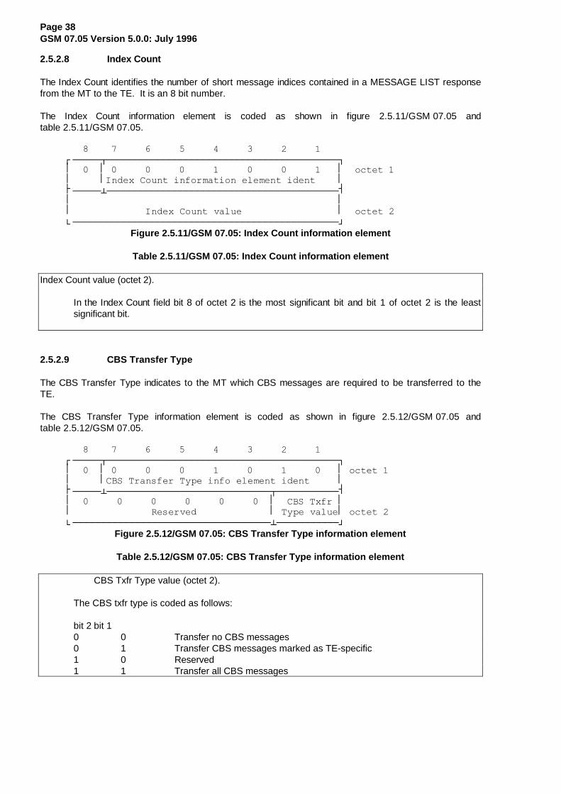
2.5.2.8 Index Count
The Index Count identifies the number of short message indices contained in a MESSAGE LIST responsefrom the MT to the TE. It is an 8 bit number.
The Index Count information element is coded as shown in figure 2.5.11/GSM 07.05 andtable 2.5.11/GSM 07.05.
���������������������������������������������¸¶¶¶¶¶¾¶¶¶¶¶¶¶¶¶¶¶¶¶¶¶¶¶¶¶¶¶¶¶¶¶¶¶¶¶¶¶¶¶¶¶¶¶¶¶¶¶¹·�����·�����������������������������������������·��RFWHW��·�����·,QGH[�&RXQW�LQIRUPDWLRQ�HOHPHQW�LGHQW����·¼¶¶¶¶¶¿¶¶¶¶¶¶¶¶¶¶¶¶¶¶¶¶¶¶¶¶¶¶¶¶¶¶¶¶¶¶¶¶¶¶¶¶¶¶¶¶¶½·�����������������������������������������������··�������������,QGH[�&RXQW�YDOXH�����������������·��RFWHW��º¶¶¶¶¶¶¶¶¶¶¶¶¶¶¶¶¶¶¶¶¶¶¶¶¶¶¶¶¶¶¶¶¶¶¶¶¶¶¶¶¶¶¶¶¶¶¶»
Figure 2.5.11/GSM 07.05: Index Count information element
Table 2.5.11/GSM 07.05: Index Count information element
Index Count value (octet 2).
In the Index Count field bit 8 of octet 2 is the most significant bit and bit 1 of octet 2 is the leastsignificant bit.
2.5.2.9 CBS Transfer Type
The CBS Transfer Type indicates to the MT which CBS messages are required to be transferred to theTE.
The CBS Transfer Type information element is coded as shown in figure 2.5.12/GSM 07.05 andtable 2.5.12/GSM 07.05.
���������������������������������������������¸¶¶¶¶¶¾¶¶¶¶¶¶¶¶¶¶¶¶¶¶¶¶¶¶¶¶¶¶¶¶¶¶¶¶¶¶¶¶¶¶¶¶¶¶¶¶¶¹·�����·�����������������������������������������·�RFWHW��·�����·&%6�7UDQVIHU�7\SH�LQIR�HOHPHQW�LGHQW�����·¼¶¶¶¶¶¿¶¶¶¶¶¶¶¶¶¶¶¶¶¶¶¶¶¶¶¶¶¶¶¶¶¶¶¶¶¾¶¶¶¶¶¶¶¶¶¶¶½·�����������������������������������·��&%6�7[IU�··��������������5HVHUYHG�������������·�7\SH�YDOXH·�RFWHW��º¶¶¶¶¶¶¶¶¶¶¶¶¶¶¶¶¶¶¶¶¶¶¶¶¶¶¶¶¶¶¶¶¶¶¶¿¶¶¶¶¶¶¶¶¶¶¶»
Figure 2.5.12/GSM 07.05: CBS Transfer Type information element
Table 2.5.12/GSM 07.05: CBS Transfer Type information element
CBS Txfr Type value (octet 2).
The CBS txfr type is coded as follows:
bit 2 bit 10 0 Transfer no CBS messages0 1 Transfer CBS messages marked as TE-specific1 0 Reserved1 1 Transfer all CBS messages
Page 39GSM 07.05 Version 5.0.0: July 1996
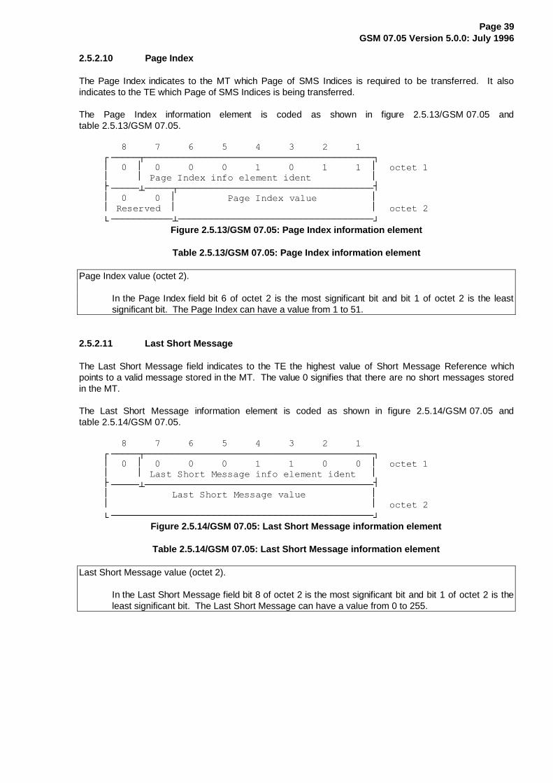
2.5.2.10 Page Index
The Page Index indicates to the MT which Page of SMS Indices is required to be transferred. It alsoindicates to the TE which Page of SMS Indices is being transferred.
The Page Index information element is coded as shown in figure 2.5.13/GSM 07.05 andtable 2.5.13/GSM 07.05.
����������������������������������������������¸¶¶¶¶¶¾¶¶¶¶¶¶¶¶¶¶¶¶¶¶¶¶¶¶¶¶¶¶¶¶¶¶¶¶¶¶¶¶¶¶¶¶¶¶¶¶¶¹·�����·�����������������������������������������·��RFWHW��·�����·�3DJH�,QGH[�LQIR�HOHPHQW�LGHQW�����������·¼¶¶¶¶¶¿¶¶¶¶¶¾¶¶¶¶¶¶¶¶¶¶¶¶¶¶¶¶¶¶¶¶¶¶¶¶¶¶¶¶¶¶¶¶¶¶¶½·�����������·���������3DJH�,QGH[�YDOXH����������··�5HVHUYHG��·�����������������������������������·��RFWHW��º¶¶¶¶¶¶¶¶¶¶¶¿¶¶¶¶¶¶¶¶¶¶¶¶¶¶¶¶¶¶¶¶¶¶¶¶¶¶¶¶¶¶¶¶¶¶¶»
Figure 2.5.13/GSM 07.05: Page Index information element
Table 2.5.13/GSM 07.05: Page Index information element
Page Index value (octet 2).
In the Page Index field bit 6 of octet 2 is the most significant bit and bit 1 of octet 2 is the leastsignificant bit. The Page Index can have a value from 1 to 51.
2.5.2.11 Last Short Message
The Last Short Message field indicates to the TE the highest value of Short Message Reference whichpoints to a valid message stored in the MT. The value 0 signifies that there are no short messages storedin the MT.
The Last Short Message information element is coded as shown in figure 2.5.14/GSM 07.05 andtable 2.5.14/GSM 07.05.
����������������������������������������������¸¶¶¶¶¶¾¶¶¶¶¶¶¶¶¶¶¶¶¶¶¶¶¶¶¶¶¶¶¶¶¶¶¶¶¶¶¶¶¶¶¶¶¶¶¶¶¶¹·�����·�����������������������������������������·��RFWHW��·�����·�/DVW�6KRUW�0HVVDJH�LQIR�HOHPHQW�LGHQW���·¼¶¶¶¶¶¿¶¶¶¶¶¶¶¶¶¶¶¶¶¶¶¶¶¶¶¶¶¶¶¶¶¶¶¶¶¶¶¶¶¶¶¶¶¶¶¶¶½·�����������/DVW�6KRUW�0HVVDJH�YDOXH������������··�����������������������������������������������·��RFWHW��º¶¶¶¶¶¶¶¶¶¶¶¶¶¶¶¶¶¶¶¶¶¶¶¶¶¶¶¶¶¶¶¶¶¶¶¶¶¶¶¶¶¶¶¶¶¶¶»
Figure 2.5.14/GSM 07.05: Last Short Message information element
Table 2.5.14/GSM 07.05: Last Short Message information element
Last Short Message value (octet 2).
In the Last Short Message field bit 8 of octet 2 is the most significant bit and bit 1 of octet 2 is theleast significant bit. The Last Short Message can have a value from 0 to 255.

Page 40GSM 07.05 Version 5.0.0: July 1996
2.5.2.12 Confirm Type
The Confirm Type field indicates the message to which the REQUEST CONFIRM is a response.
The Confirm Type information element is coded as shown in figure 2.5.15/GSM 07.05 andtable 2.5.15/GSM 07.05.
����������������������������������������������¸¶¶¶¶¶¾¶¶¶¶¶¶¶¶¶¶¶¶¶¶¶¶¶¶¶¶¶¶¶¶¶¶¶¶¶¶¶¶¶¶¶¶¶¶¶¶¶¹·�����·�����������������������������������������·��RFWHW��·�����·�����&RQILUP�7\SH�LQIR�HOHPHQW�LGHQW�����·¼¶¶¶¶¶¿¶¶¶¶¶¶¶¶¶¶¶¶¶¶¶¶¶¶¶¶¶¶¶¶¶¶¶¶¶¶¶¶¶¶¶¶¶¶¶¶¶½·��������������&RQILUP�7\SH�YDOXH���������������··�����������������������������������������������·��RFWHW��º¶¶¶¶¶¶¶¶¶¶¶¶¶¶¶¶¶¶¶¶¶¶¶¶¶¶¶¶¶¶¶¶¶¶¶¶¶¶¶¶¶¶¶¶¶¶¶»
Figure 2.5.15/GSM 07.05: Confirm Type information element
Table 2.5.15/GSM 07.05: Confirm Type information element
Confirm Type value (octet 2).
The Confirm Type is coded as follows:
8 7 6 5 4 3 2 10 0 0 0 0 0 0 0 Reserved
0 0 0 0 0 0 0 1 Confirm request to transfer incomingSMS messages
0 0 0 0 0 0 1 0 Confirm request to transfer incomingCBS messages
0 0 0 0 0 0 1 1 Confirm request to indicate arrival ofmessages in MT
0 0 0 0 0 1 0 0 Confirm request to attempt to sendshort message (actual send is confirmedlater: see section 3.3)
All other values are reserved.

Page 41GSM 07.05 Version 5.0.0: July 1996
2.5.2.13 TP-Failure Cause
This optional field is present if provided by the Relay Layer. The TP-Failure Cause is provided from theService Centre and indicates to the TE the reason why the delivery of the message was unsuccessful. TheTP-Failure cause information element is coded as shown in figure 2.5.16/GSM 07.05 andtable 2.5.16/GSM 07.05.
����������������������������������������������¸¶¶¶¶¶¾¶¶¶¶¶¶¶¶¶¶¶¶¶¶¶¶¶¶¶¶¶¶¶¶¶¶¶¶¶¶¶¶¶¶¶¶¶¶¶¶¶¹·�����·�����������������������������������������·�RFWHW��·�����·�&DXVH�LQIRUPDWLRQ�HOHPHQW�LGHQWLILHU����·¼¶¶¶¶¶¿¶¶¶¶¶¶¶¶¶¶¶¶¶¶¶¶¶¶¶¶¶¶¶¶¶¶¶¶¶¶¶¶¶¶¶¶¶¶¶¶¶½·�����������������������������������������������··�����/HQJWK�RI�)DLOXUH�FDXVH�ILHOG�������������·�RFWHW��¼¶¶¶¶¶¶¶¶¶¶¶¶¶¶¶¶¶¶¶¶¶¶¶¶¶¶¶¶¶¶¶¶¶¶¶¶¶¶¶¶¶¶¶¶¶¶¶½·�����������������������������������������������··��������������)DLOXUH�FDXVH��������������������·RFWHWV����º¶¶¶¶¶¶¶¶¶¶¶¶¶¶¶¶¶¶¶¶¶¶¶¶¶¶¶¶¶¶¶¶¶¶¶¶¶¶¶¶¶¶¶¶¶¶¶»
Figure 2.5.16/GSM 07.05: TP -Failure Cause information element
Table 2.5.16/GSM 07.05: TP -Failure Cause information element
Failure cause (octet 3-4)
The failure cause contained in this field is directly mapped from the TP-Failure Cause (TP-FCS)field of the SMS-SUBMIT-REPORT message defined in GSM 03.40.

Page 42GSM 07.05 Version 5.0.0: July 1996
3. Text Mode
3.1 Parameter Definitions
The following parameters are used in the subsequent sections which describe all commands. The formatsof integer and string types referenced here are defined in V.25ter. The default values are for commandparameters, not for result code parameters.
Message Storage Parameters
<index> integer type; value in the range of location numbers supported by the associated memory
<mem1> string type; memory from which messages are read and deleted (commands List Messages+CMGL, Read Message +CMGR and Delete Message +CMGD); defined values (others aremanufacturer specific):
"BM" broadcast message storage"ME" ME message storage"MT" any of the storages associated with ME"SM" SIM message storage"TA" TA message storage"SR" status report storage
<mem2> string type; memory to which writing and sending operations are made (commands SendMessage from Storage +CMSS and Write Message to Memory +CMGW)
<mem3> string type; memory to which received SMs are preferred to be stored (unless forwardeddirectly to TE; refer command New Message Indications +CNMI); refer <mem1> for definedvalues; received CBMs are always stored in "BM" (or some manufacturer specific storage)unless directly forwarded to TE; received status reports are always stored in "SR" (or somemanufacturer specific storage) unless directly forwarded to TE
<stat> integer type in PDU mode (default 0), or string type in text mode (default "REC UNREAD");indicates the status of message in memory; defined values:
0 "REC UNREAD" received unread message (i.e. new message)1 "REC READ" received read message2 "STO UNSENT" stored unsent message (only applicable to SMs)3 "STO SENT" stored sent message (only applicable to SMs)4 "ALL" all messages (only applicable to +CMGL command)
<total1> integer type; total number of message locations in <mem1>
<total2> integer type; total number of message locations in <mem2>
<total3> integer type; total number of message locations in <mem3>
<used1> integer type; number of messages currently in <mem1>
<used2> integer type; number of messages currently in <mem2>
<used3> integer type; number of messages currently in <mem3>

Page 43GSM 07.05 Version 5.0.0: July 1996
Message Data Parameters
<alpha> string type alphanumeric representation of <da> or <oa> corresponding to the entry found inMT phonebook; implementation of this feature is manufacturer specific; used character setshould be the one selected with command Select TE Character Set +CSCS ( see definition ofthis command in TS 07.07)
<ct> GSM 03.40 TP-Command-Type in integer format (default 0)
<da> GSM 03.40 TP-Destination-Address Address-Value field in string format; BCD numbers (orGSM default alphabet characters) are converted to characters of the currently selected TEcharacter set (refer command +CSCS in TS 07.07); type of address given by <toda>
<data> GSM 03.40 TP-User-Data in text mode responses; format:
- if <dcs> indicates that GSM 03.38 default alphabet is used and <fo> indicates thatGSM 03.40 TP-User-Data-Header-Indication is not set:
- if TE character set other than "HEX" (refer command Select TE Character Set+CSCS in TS 07.07): ME/TA converts GSM alphabet into current TE characterset according to rules of Annex A
- if TE character set is "HEX" : ME/TA converts each 7-bit character ofGSM alphabet into two IRA character long hexadecimal number (e.g. characterΠ (GSM 23) is presented as 17 (IRA 49 and 55))
- if <dcs> indicates that 8-bit data coding scheme is used or <fo> indicates thatGSM 03.40 TP-User-Data-Header-Indication is set: ME/TA converts each 8-bit octetinto two IRA character long hexadecimal number (e.g. octet with integer value 42 ispresented to TE as two characters 2A (IRA 50 and 65))
<dcs> depending on the command or result code: GSM 03.38 SMS Data Coding Scheme (default0), or Cell Broadcast Data Coding Scheme in integer format
<dt> GSM 03.40 TP-Discharge-Time in time-string format: "yy/MM/dd,hh:mm:ss±zz", wherecharacters indicate year (two last digits), month, day, hour, minutes, seconds and time zone.E.g. 6th of May 1994, 22:10:00 GMT+2 hours equals to "94/05/06,22:10:00+08"
<fo> depending on the command or result code: first octet of GSM 03.40 SMS-DELIVER,SMS-SUBMIT (default 17), SMS-STATUS-REPORT, or SMS-COMMAND (default 2) ininteger format
<length> integer type value indicating in the text mode (+CMGF=1) the length of the message body<data> in characters; or in PDU mode (+CMGF=0), the length of the actual TP data unit inoctets (i.e. the RP layer SMSC address octets are not counted in the length)
<mid> GSM 03.41 CBM Message Identifier in integer format
<mn> GSM 03.40 TP-Message-Number in integer format
<mr> GSM 03.40 TP-Message-Reference in integer format
<oa> GSM 03.40 TP-Originating-Address Address-Value field in string format; BCD numbers (orGSM default alphabet characters) are converted to characters of the currently selected TEcharacter set (refer command +CSCS in TS 07.07 ); type of address given by <tooa>
<page> GSM 03.41 CBM Page Parameter bits 4-7 in integer format

Page 44GSM 07.05 Version 5.0.0: July 1996
<pages> GSM 03.41 CBM Page Parameter bits 0-3 in integer format
<pdu> In the case of SMS: GSM 04.11 SC address followed by GSM 03.40 TPDU in hexadecimalformat: ME/TA converts each octet of TP data unit into two IRA character long hexadecimalnumber (e.g. octet with integer value 42 is presented to TE as two characters 2A (IRA 50 and65))
In the case of CBS: GSM 03.41 TPDU in hexadecimal format
<pid> GSM 03.40 TP-Protocol-Identifier in integer format (default 0)
<ra> GSM 03.40 TP-Recipient-Address Address-Value field in string format; BCD numbers (orGSM default alphabet characters) are converted to characters of the currently selected TEcharacter set (refer command +CSCS in TS 07.07 ); type of address given by <tora>
<sca> GSM 04.11 RP SC address Address-Value field in string format; BCD numbers (orGSM default alphabet characters) are converted to characters of the currently selected TEcharacter set (refer command +CSCS in TS 07.07 ); type of address given by <tosca>
<scts> GSM 03.40 TP-Service-Centre-Time-Stamp in time-string format (refer <dt> )
<sn> GSM 03.41 CBM Serial Number in integer format
<st> GSM 03.40 TP-Status in integer format
<toda> GSM 04.11 TP-Destination-Address Type-of-Address octet in integer format (when firstcharacter of <da> is + (IRA 43) default is 145, otherwise default is 129)
<tooa> GSM 04.11 TP-Originating-Address Type-of-Address octet in integer format (default refer<toda> )
<tora> GSM 04.11 TP-Recipient-Address Type-of-Address octet in integer format (default refer<toda> )
<tosca> GSM 04.11 RP SC address Type-of-Address octet in integer format (default refer <toda> )
<vp> depending on SMS-SUBMIT <fo> setting: GSM 03.40 TP-Validity-Period either in integerformat (default 167) or in time-string format (refer <dt> )

Page 45GSM 07.05 Version 5.0.0: July 1996
3.2 General Configuration Commands
3.2.1 Select Message Service +CSMS
Parameter Command Syntax
Command Possible response(s)+CSMS=<service> +CSMS: <mt>,<mo>,<bm>
+CMS ERROR: <err>+CSMS? +CSMS: <service>,<mt>,<mo>,<bm>+CSMS=? +CSMS: ( list of supported <service> s)
Description
Set command selects messaging service <service> . It returns the types of messages supported by theME: <mt> for mobile terminated messages, <mo> for mobile originated messages and <bm> for broadcasttype messages. If chosen service is not supported by the ME (but is supported by the TA), final resultcode +CMS ERROR: <err> shall be returned. See chapter Message Service Failure Result Code for alist of <err> values.
Also read command returns supported message types along the current service setting.
Test command returns a list of all services supported by the TA.
Defined Values
<service> :0 GSM 03.40 and 03.411...127 reserved128... manufacturer specific
<mt> , <mo>, <bm>:0 type not supported1 type supported
Implementation
Mandatory.

Page 46GSM 07.05 Version 5.0.0: July 1996
3.2.2 Preferred Message Storage +CPMS
Parameter Command Syntax
Command Possible response(s)+CPMS=<mem1>[,<mem2>[,<mem3>]]
+CPMS: <used1>,<total1>,<used2>,<total2>,<used3>,<total3>+CMS ERROR: <err>
+CPMS? +CPMS: <mem1>,<used1>,<total1>,<mem2>,<used2>,<total2>,<mem3>,<used3>,<total3>+CMS ERROR: <err>
+CPMS=? +CPMS: ( list of supported <mem1>s),( list of supported <mem2>s),( list of supported <mem3>s)
Description
Set command selects memory storages <mem1> and <mem2> to be used for reading, writing, etc. Ifchosen storage is not appropriate for the ME (but is supported by the TA), final result code +CMS ERROR:<err> shall be returned. See chapter Message Service Failure Result Code for a list of possible <err>values.
Test command returns lists of memory storages supported by the TA.
Implementation
Mandatory.
3.2.3 Message Format +CMGF
Parameter Command Syntax
Command Possible response(s)+CMGF=[<mode>]+CMGF? +CMGF: <mode>+CMGF=? +CMGF: ( list of supported <mode>s)
Description
Set command tells the TA, which input and output format of messages to use. <mode> indicates theformat of messages used with send, list, read and write commands and unsolicited result codes resultingfrom received messages. Mode can be either PDU mode (entire TP data units used) or text mode(headers and body of the messages given as separate parameters). Text mode uses the value ofparameter <chset> specified by command Select TE Character Set +CSCS to inform the character set tobe used in the message body in the TA-TE interface.
Test command returns supported modes as a compound value.
Defined Values
<mode>:0 PDU mode (default when implemented)1 text mode
Implementation
Mandatory also when only one mode implemented.

Page 47GSM 07.05 Version 5.0.0: July 1996
3.2.4 Enter SMS Block Mode Protocol +CESP
Action Command Syntax
Command Possible response(s)+CESP+CESP=?
Description
Execution command sets the TA in SMS block protocol mode. Final result code OK (or 0) shall not bereturned until block mode is exited.
Implementation
Mandatory when block mode implemented.
3.2.5 Message Service Failure Result Code +CMS ERROR
Final result code +CMS ERROR: <err> indicates an error related to mobile equipment or network. Theoperation is similar to ERROR result code. None of the following commands in the same command line isexecuted. Neither ERROR nor OK result code shall be returned. ERROR is returned normally when error isrelated to syntax or invalid parameters.
Defined Values
<err> values used by common messaging commands:0...127 GSM 04.11 Annex E-2 values128...255 GSM 03.40 section 9.2.3.22 values300 ME failure301 SMS service of ME reserved302 operation not allowed303 operation not supported304 invalid PDU mode parameter305 invalid text mode parameter310 SIM not inserted311 SIM PIN necessary312 PH-SIM PIN necessary313 SIM failure314 SIM busy315 SIM wrong320 memory failure321 invalid memory index322 memory full330 SMSC address unknown331 no network service332 network timeout500 unknown error...511 other values in range 256...511 are reserved512... manufacturer specific
Implementation
Mandatory.

Page 48GSM 07.05 Version 5.0.0: July 1996
3.2.6 Informative Examples
Setting up a TA supporting GSM SMS:
AT+CSMS=? (inquiry of available services in TA)+CSMS: (0) (only GSM SMS implemented)OKAT+CSMS=0;+CPMS=? (set GSM SMS; query available memories)+CSMS: 1,1,1 (all MT, MO and CBM supported)+CPMS: ("BM","ME","SM"),("ME","SM"),("ME","SM") (CBM, ME and SIM memoriesOK for reading, ME and SIM memories for writing)AT+CPMS="ME","ME","ME";+CMGF=? (set ME memory; query available message formats)+CPMS: "ME",5,99,"ME",5,99,"ME",5,99 (five messages in ME, 99 total space)+CMGF: (0,1) (both text and PDU mode implemented)OKAT+CMGF=1;+CSCS=? (select text mode; query available TE character sets)+CSCS: ("IRA","PCCP437","8859-1")OKAT+CSCS="PCCP437" (select PC code page 437)OK
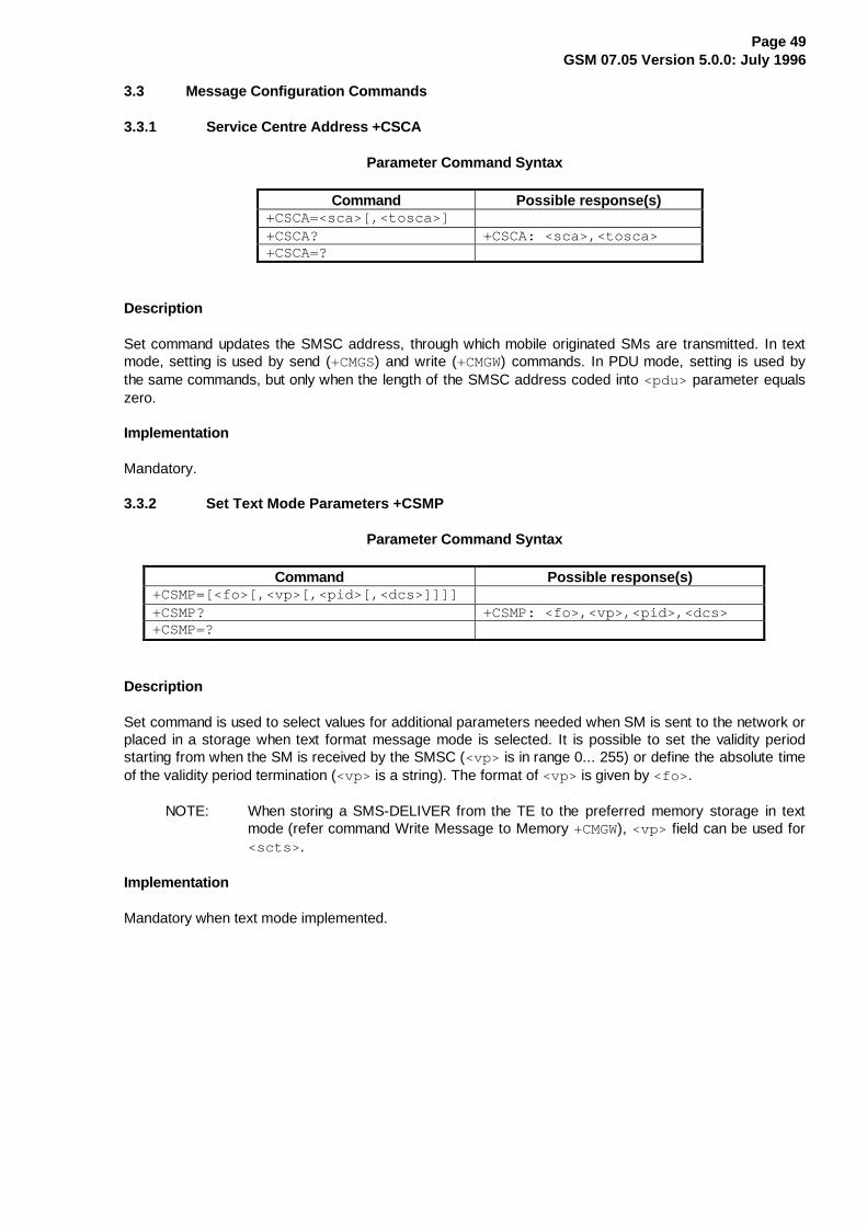
Page 49GSM 07.05 Version 5.0.0: July 1996
3.3 Message Configuration Commands
3.3.1 Service Centre Address +CSCA
Parameter Command Syntax
Command Possible response(s)+CSCA=<sca>[,<tosca>]+CSCA? +CSCA: <sca>,<tosca>+CSCA=?
Description
Set command updates the SMSC address, through which mobile originated SMs are transmitted. In textmode, setting is used by send (+CMGS) and write (+CMGW) commands. In PDU mode, setting is used bythe same commands, but only when the length of the SMSC address coded into <pdu> parameter equalszero.
Implementation
Mandatory.
3.3.2 Set Text Mode Parameters +CSMP
Parameter Command Syntax
Command Possible response(s)+CSMP=[<fo>[,<vp>[,<pid>[,<dcs>]]]]+CSMP? +CSMP: <fo>,<vp>,<pid>,<dcs>+CSMP=?
Description
Set command is used to select values for additional parameters needed when SM is sent to the network orplaced in a storage when text format message mode is selected. It is possible to set the validity periodstarting from when the SM is received by the SMSC (<vp> is in range 0... 255) or define the absolute timeof the validity period termination (<vp> is a string). The format of <vp> is given by <fo> .
NOTE: When storing a SMS-DELIVER from the TE to the preferred memory storage in textmode (refer command Write Message to Memory +CMGW), <vp> field can be used for<scts> .
Implementation
Mandatory when text mode implemented.
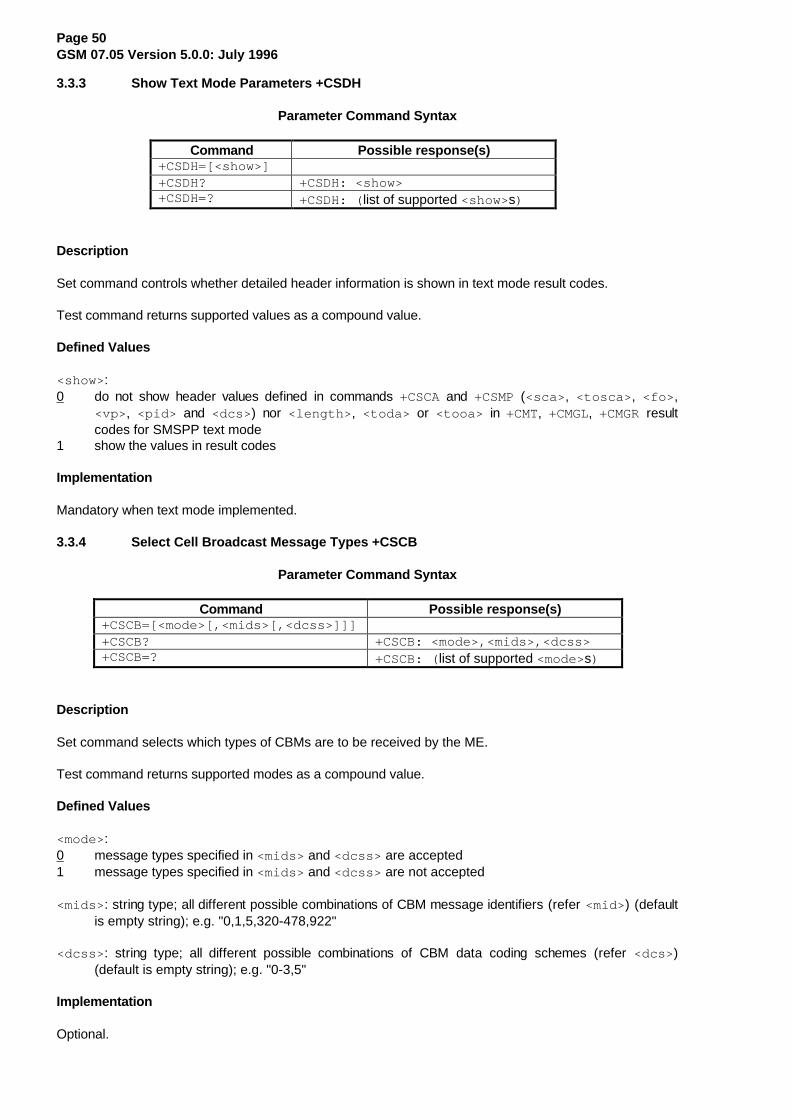
Page 50GSM 07.05 Version 5.0.0: July 1996
3.3.3 Show Text Mode Parameters +CSDH
Parameter Command Syntax
Command Possible response(s)+CSDH=[<show>]+CSDH? +CSDH: <show>+CSDH=? +CSDH: ( list of supported <show>s)
Description
Set command controls whether detailed header information is shown in text mode result codes.
Test command returns supported values as a compound value.
Defined Values
<show> :0 do not show header values defined in commands +CSCA and +CSMP (<sca> , <tosca> , <fo> ,
<vp> , <pid> and <dcs> ) nor <length> , <toda> or <tooa> in +CMT, +CMGL, +CMGR resultcodes for SMSPP text mode
1 show the values in result codes
Implementation
Mandatory when text mode implemented.
3.3.4 Select Cell Broadcast Message Types +CSCB
Parameter Command Syntax
Command Possible response(s)+CSCB=[<mode>[,<mids>[,<dcss>]]]+CSCB? +CSCB: <mode>,<mids>,<dcss>+CSCB=? +CSCB: ( list of supported <mode>s)
Description
Set command selects which types of CBMs are to be received by the ME.
Test command returns supported modes as a compound value.
Defined Values
<mode>:0 message types specified in <mids> and <dcss> are accepted1 message types specified in <mids> and <dcss> are not accepted
<mids> : string type; all different possible combinations of CBM message identifiers (refer <mid> ) (defaultis empty string); e.g. "0,1,5,320-478,922"
<dcss> : string type; all different possible combinations of CBM data coding schemes (refer <dcs> )(default is empty string); e.g. "0-3,5"
Implementation
Optional.

Page 51GSM 07.05 Version 5.0.0: July 1996
3.3.5 Save Settings +CSAS
Action Command Syntax
Command Possible response(s)+CSAS[=<profile>] +CMS ERROR: <err>+CSAS=? +CSAS: ( list of supported <profile> s)
Description
Execution command saves active message service settings to a non-volatile memory. A TA can containseveral profiles of settings. All settings specified in commands Service Centre Address +CSCA, SetMessage Parameters +CSMP and Select Cell Broadcast Message Types +CSCB (if implemented) aresaved. See chapter Message Service Failure Result Code for <err> values.
Test command shall display the supported profile numbers for reading and writing of settings.
Defined Values
<profile> :0...255 manufacturer specific profile number where settings are to be stored
Implementation
Optional.
3.3.6 Restore Settings +CRES
Action Command Syntax
Command Possible response(s)+CRES[=<profile>] +CMS ERROR: <err>+CRES=? +CRES: ( list of supported <profile> s)
Description
Execution command restores message service settings from non-volatile memory to active memory. A TAcan contain several profiles of settings. All settings specified in commands Service Centre Address +CSCA,Set Message Parameters +CSMP and Select Cell Broadcast Message Types +CSCB (if implemented) arerestored. See chapter Message Service Failure Result Code for <err> values.
Test command shall display the supported profile numbers for reading and writing of settings.
Defined Values
<profile> :0...255 manufacturer specific profile number from where settings are to be restored
Implementation
Optional.

Page 52GSM 07.05 Version 5.0.0: July 1996
3.3.7 Informative Examples
Figure 1 illustrates an example setup of a TE-TA-ME system for GSM SMS. Location of volatile andnon-volatile parameter memories, and the operations to change the parameter values are shown. +CSMP isused to set the text mode header values of SMS-SUBMIT (or SMS-DELIVER when received message iswritten from TE to a storage). The volatile memory may as well be in the ME, or when no volatile memoryis used, +CSMP, +CSCA and +CSCB settings are stored directly to non-volatile memory of ME.
SM STORAGES
CBM STORAGES
text mode parametersfor send and write,SMSC address;non-volatile memory
text mode parametersfor send and write,SMSC address;volatile memory
cell broadcast typesto be stored;non-volatile andvolatile memories
set SMSC address +CSCA andset text mode parameters +CSMP
save +CSAS and restore +CRES
save +CSAS
power-up and restore +CRES
save to non-volatile orrestore to volatile
select cell broadcast message types +CSCB
ME TA TE
Figure 1: Message service parameter procedures
In this example, the volatile parameter settings of TA are used to construct messages in text mode. SMSCaddress setting is used also in PDU mode. The next example illustrates a session to restore the messageparameters from the ME to the TA, and to set up the CBM identifiers (and languages) which are wanted tobe received:
AT+CRES (restore settings from non-volatile memory to volatile memory)OKAT+CSMP?;+CSCA? (query SM parameters)+CSMP: 17,167,0,0 (default values for SMS-SUBMIT)+CSCA: "+358501234567",145 (SMSC address)OKAT+CSDH=1 (show all headers in text mode)OKAT+CSCB=1 (all CBMs are accepted)OK
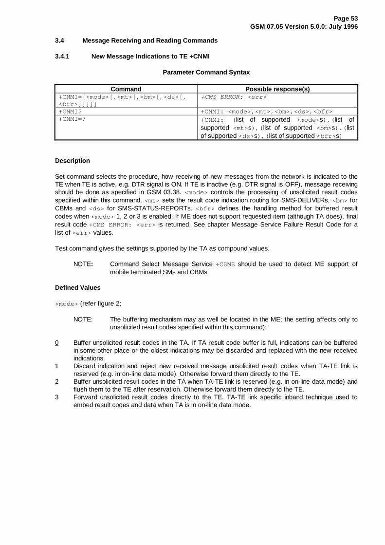
Page 53GSM 07.05 Version 5.0.0: July 1996
3.4 Message Receiving and Reading Commands
3.4.1 New Message Indications to TE +CNMI
Parameter Command Syntax
Command Possible response(s)+CNMI=[<mode>[,<mt>[,<bm>[,<ds>[,<bfr>]]]]]
+CMS ERROR: <err>
+CNMI? +CNMI: <mode>,<mt>,<bm>,<ds>,<bfr>+CNMI=? +CNMI: ( list of supported <mode>s),( list of
supported <mt>s),( list of supported <bm>s),( listof supported <ds> s),( list of supported <bfr> s)
Description
Set command selects the procedure, how receiving of new messages from the network is indicated to theTE when TE is active, e.g. DTR signal is ON. If TE is inactive (e.g. DTR signal is OFF), message receivingshould be done as specified in GSM 03.38. <mode> controls the processing of unsolicited result codesspecified within this command, <mt> sets the result code indication routing for SMS-DELIVERs, <bm> forCBMs and <ds> for SMS-STATUS-REPORTs. <bfr> defines the handling method for buffered resultcodes when <mode> 1, 2 or 3 is enabled. If ME does not support requested item (although TA does), finalresult code +CMS ERROR: <err> is returned. See chapter Message Service Failure Result Code for alist of <err> values.
Test command gives the settings supported by the TA as compound values.
NOTE: Command Select Message Service +CSMS should be used to detect ME support ofmobile terminated SMs and CBMs.
Defined Values
<mode> (refer figure 2;
NOTE: The buffering mechanism may as well be located in the ME; the setting affects only tounsolicited result codes specified within this command):
0 Buffer unsolicited result codes in the TA. If TA result code buffer is full, indications can be bufferedin some other place or the oldest indications may be discarded and replaced with the new receivedindications.
1 Discard indication and reject new received message unsolicited result codes when TA-TE link isreserved (e.g. in on-line data mode). Otherwise forward them directly to the TE.
2 Buffer unsolicited result codes in the TA when TA-TE link is reserved (e.g. in on-line data mode) andflush them to the TE after reservation. Otherwise forward them directly to the TE.
3 Forward unsolicited result codes directly to the TE. TA-TE link specific inband technique used toembed result codes and data when TA is in on-line data mode.
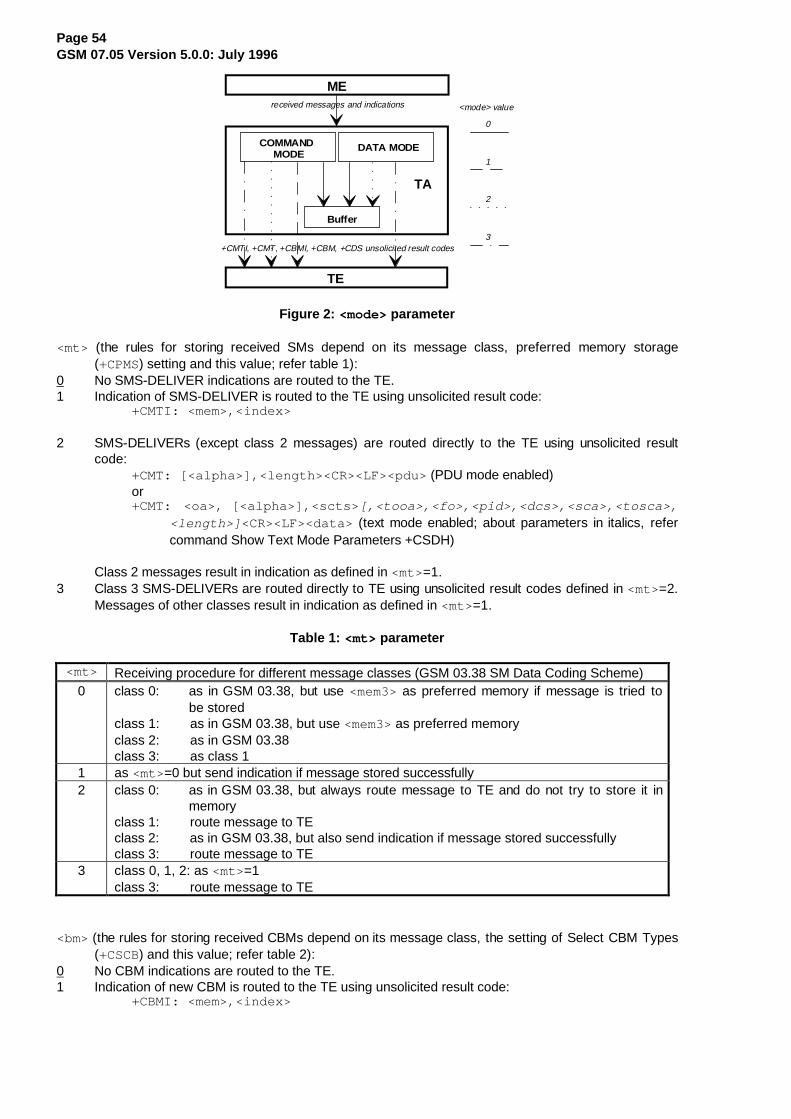
Page 54GSM 07.05 Version 5.0.0: July 1996
COMMAND MODE
DATA MODE
Buffer
TE
ME
TA
received messages and indications
0
1
2
3
<mode> value
+CMTI, +CMT, +CBMI, +CBM, +CDS unsolicited result codes
Figure 2: <mode> parameter
<mt> (the rules for storing received SMs depend on its message class, preferred memory storage(+CPMS) setting and this value; refer table 1):
0 No SMS-DELIVER indications are routed to the TE.1 Indication of SMS-DELIVER is routed to the TE using unsolicited result code:
+CMTI: <mem>,<index>
2 SMS-DELIVERs (except class 2 messages) are routed directly to the TE using unsolicited resultcode:
+CMT: [<alpha>],<length><CR><LF><pdu> (PDU mode enabled)or+CMT: <oa>, [<alpha>],<scts> [,<tooa>,<fo>,<pid>,<dcs>,<sca>,<tosca>,
<length>] <CR><LF><data> (text mode enabled; about parameters in italics, refercommand Show Text Mode Parameters +CSDH)
Class 2 messages result in indication as defined in <mt>=1.3 Class 3 SMS-DELIVERs are routed directly to TE using unsolicited result codes defined in <mt>=2.
Messages of other classes result in indication as defined in <mt>=1.
Table 1: <mt> parameter
<mt> Receiving procedure for different message classes (GSM 03.38 SM Data Coding Scheme)0 class 0: as in GSM 03.38, but use <mem3> as preferred memory if message is tried to
be storedclass 1: as in GSM 03.38, but use <mem3> as preferred memoryclass 2: as in GSM 03.38class 3: as class 1
1 as <mt>=0 but send indication if message stored successfully2 class 0: as in GSM 03.38, but always route message to TE and do not try to store it in
memoryclass 1: route message to TEclass 2: as in GSM 03.38, but also send indication if message stored successfullyclass 3: route message to TE
3 class 0, 1, 2: as <mt>=1class 3: route message to TE
<bm> (the rules for storing received CBMs depend on its message class, the setting of Select CBM Types(+CSCB) and this value; refer table 2):
0 No CBM indications are routed to the TE.1 Indication of new CBM is routed to the TE using unsolicited result code:
+CBMI: <mem>,<index>
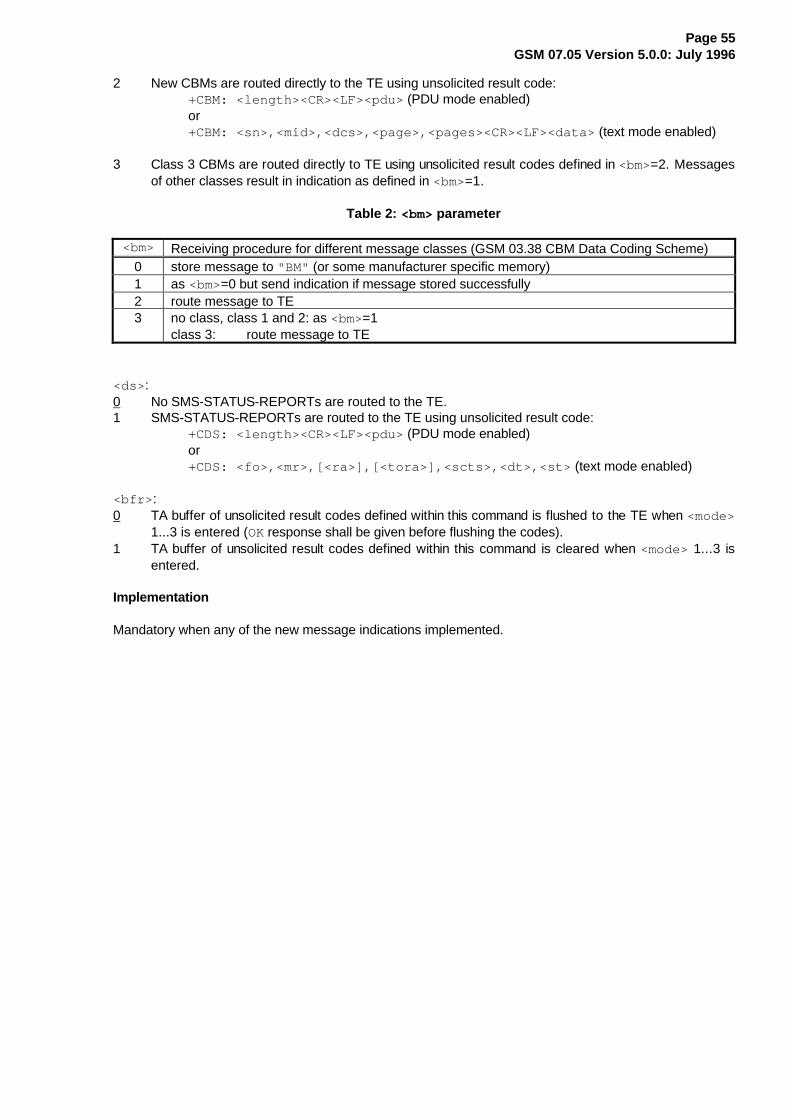
Page 55GSM 07.05 Version 5.0.0: July 1996
2 New CBMs are routed directly to the TE using unsolicited result code:+CBM: <length><CR><LF><pdu> (PDU mode enabled)or+CBM: <sn>,<mid>,<dcs>,<page>,<pages><CR><LF><data> (text mode enabled)
3 Class 3 CBMs are routed directly to TE using unsolicited result codes defined in <bm>=2. Messagesof other classes result in indication as defined in <bm>=1.
Table 2: <bm> parameter
<bm> Receiving procedure for different message classes (GSM 03.38 CBM Data Coding Scheme)0 store message to "BM" (or some manufacturer specific memory)1 as <bm>=0 but send indication if message stored successfully2 route message to TE3 no class, class 1 and 2: as <bm>=1
class 3: route message to TE
<ds> :0 No SMS-STATUS-REPORTs are routed to the TE.1 SMS-STATUS-REPORTs are routed to the TE using unsolicited result code:
+CDS: <length><CR><LF><pdu> (PDU mode enabled)or+CDS: <fo>,<mr>,[<ra>],[<tora>],<scts>,<dt>,<st> (text mode enabled)
<bfr> :0 TA buffer of unsolicited result codes defined within this command is flushed to the TE when <mode>
1...3 is entered (OK response shall be given before flushing the codes).1 TA buffer of unsolicited result codes defined within this command is cleared when <mode> 1...3 is
entered.
Implementation
Mandatory when any of the new message indications implemented.
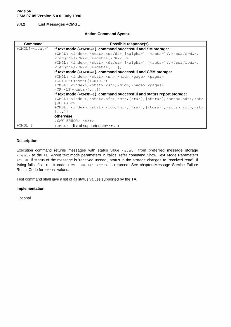
Page 56GSM 07.05 Version 5.0.0: July 1996
3.4.2 List Messages +CMGL
Action Command Syntax
Command Possible response(s)+CMGL[=<stat>] if text mode ( +CMGF=1), command successful and SM storage:
+CMGL: <index>,<stat>,<oa/da>,[<alpha>],[<scts>] [,<tooa/toda>,<length>] <CR><LF><data>[<CR><LF>+CMGL: <index>,<stat>,<da/oa>,[<alpha>],[<scts>] [,<tooa/toda>,<length>] <CR><LF><data>[...]]if text mode ( +CMGF=1), command successful and CBM storage:+CMGL: <index>,<stat>,<sn>,<mid>,<page>,<pages><CR><LF><data>[<CR><LF>+CMGL: <index>,<stat>,<sn>,<mid>,<page>,<pages><CR><LF><data>[...]]if text mode ( +CMGF=1), command successful and status report storage:+CMGL: <index>,<stat>,<fo>,<mr>,[<ra>],[<tora>],<scts>,<dt>,<st>[<CR><LF>+CMGL: <index>,<stat>,<fo>,<mr>,[<ra>],[<tora>],<scts>,<dt>,<st>[...]]otherwise:+CMS ERROR: <err>
+CMGL=? +CMGL: ( list of supported <stat> s)
Description
Execution command returns messages with status value <stat> from preferred message storage<mem1> to the TE. About text mode parameters in italics, refer command Show Text Mode Parameters+CSDH. If status of the message is 'received unread', status in the storage changes to 'received read'. Iflisting fails, final result code +CMS ERROR: <err> is returned. See chapter Message Service FailureResult Code for <err> values.
Test command shall give a list of all status values supported by the TA.
Implementation
Optional.
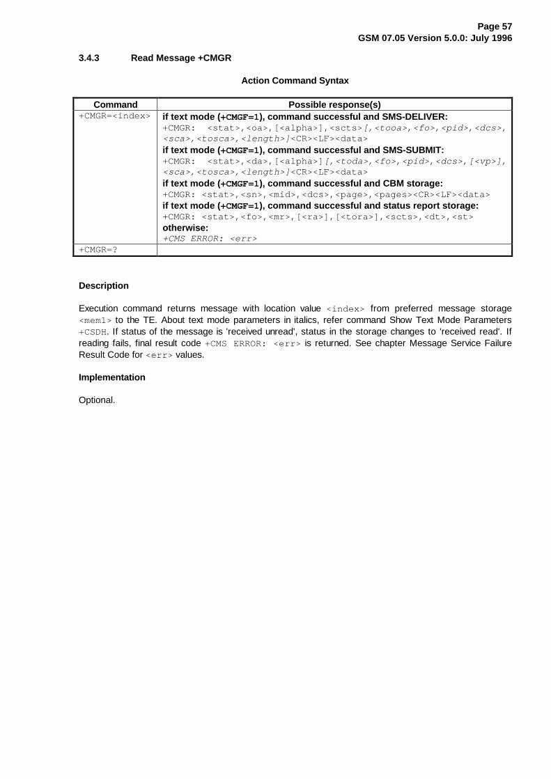
Page 57GSM 07.05 Version 5.0.0: July 1996
3.4.3 Read Message +CMGR
Action Command Syntax
Command Possible response(s)+CMGR=<index> if text mode ( +CMGF=1), command successful and SMS-DELIVER:
+CMGR: <stat>,<oa>,[<alpha>],<scts> [,<tooa>,<fo>,<pid>,<dcs>,<sca>,<tosca>,<length>] <CR><LF><data>if text mode ( +CMGF=1), command successful and SMS-SUBMIT:+CMGR: <stat>,<da>,[<alpha>] [,<toda>,<fo>,<pid>,<dcs>,[<vp>],<sca>,<tosca>,<length>] <CR><LF><data>if text mode ( +CMGF=1), command successful and CBM storage:+CMGR: <stat>,<sn>,<mid>,<dcs>,<page>,<pages><CR><LF><data>if text mode ( +CMGF=1), command successful and status report storage:+CMGR: <stat>,<fo>,<mr>,[<ra>],[<tora>],<scts>,<dt>,<st>otherwise:+CMS ERROR: <err>
+CMGR=?
Description
Execution command returns message with location value <index> from preferred message storage<mem1> to the TE. About text mode parameters in italics, refer command Show Text Mode Parameters+CSDH. If status of the message is 'received unread', status in the storage changes to 'received read'. Ifreading fails, final result code +CMS ERROR: <err> is returned. See chapter Message Service FailureResult Code for <err> values.
Implementation
Optional.
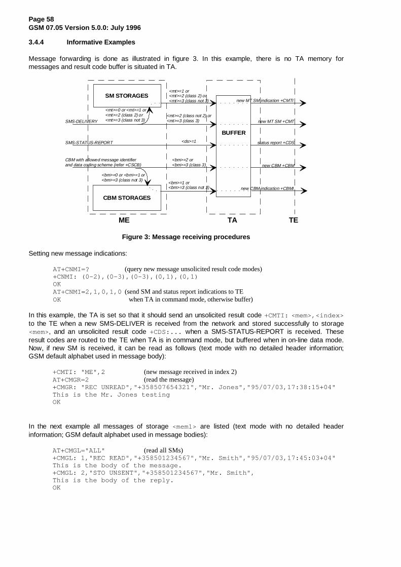
Page 58GSM 07.05 Version 5.0.0: July 1996
3.4.4 Informative Examples
Message forwarding is done as illustrated in figure 3. In this example, there is no TA memory formessages and result code buffer is situated in TA.
SM STORAGES
CBM STORAGES
ME TA TE
BUFFER
new MT SM indication +CMTI
new CBM indication +CBMI
SMS-DELIVERY
SMS-STATUS-REPORT
CBM with allowed message identifierand data coding scheme (refer +CSCB)
<mt>=0 or <mt>=1 or<mt>=2 (class 2) or<mt>=3 (class not 3)
<mt>=2 (class not 2) or<mt>=3 (class 3) new MT SM +CMT
status report +CDS
new CBM +CBM
<bm>=0 or <bm>=1 or<bm>=3 (class not 3)
<bm>=2 or<bm>=3 (class 3)
<mt>=1 or<mt>=2 (class 2) or<mt>=3 (class not 3)
<bm>=1 or<bm>=3 (class not 3)
<ds>=1
Figure 3: Message receiving procedures
Setting new message indications:
AT+CNMI=? (query new message unsolicited result code modes)+CNMI: (0-2),(0-3),(0-3),(0,1),(0,1)OKAT+CNMI=2,1,0,1,0 (send SM and status report indications to TEOK when TA in command mode, otherwise buffer)
In this example, the TA is set so that it should send an unsolicited result code +CMTI: <mem>,<index>to the TE when a new SMS-DELIVER is received from the network and stored successfully to storage<mem>, and an unsolicited result code +CDS:... when a SMS-STATUS-REPORT is received. Theseresult codes are routed to the TE when TA is in command mode, but buffered when in on-line data mode.Now, if new SM is received, it can be read as follows (text mode with no detailed header information;GSM default alphabet used in message body):
+CMTI: "ME",2 (new message received in index 2)AT+CMGR=2 (read the message)+CMGR: "REC UNREAD","+358507654321","Mr. Jones","95/07/03,17:38:15+04"This is the Mr. Jones testingOK
In the next example all messages of storage <mem1> are listed (text mode with no detailed headerinformation; GSM default alphabet used in message bodies):
AT+CMGL="ALL" (read all SMs)+CMGL: 1,"REC READ","+358501234567","Mr. Smith","95/07/03,17:45:03+04"This is the body of the message.+CMGL: 2,"STO UNSENT","+358501234567","Mr. Smith",This is the body of the reply.OK

Page 59GSM 07.05 Version 5.0.0: July 1996
The next example shows a method to read new CBMs received from the network (text mode; GSM defaultalphabet used in message bodies):
AT+CNMI=2,,2,,0 (CBMs will be sent to the TE)OKAT+CPMS="BM";+CMGL (select CBM memory for reading; list all unread CBMs)+CMGL: 1,"REC UNREAD",100,40,1,3 (first page of three page weather information)Weather in Finland 3rd of July 1995+CMGL: 2,"REC UNREAD",100,40,2,3 (second page of three page weather information)Helsinki: cloudy, snow storms, -20 degrees Celsius, wind -14 m/s NE+CMGL: 3,"REC UNREAD",100,40,3,3 (third page of three page weather information)Tampere: sunny, 40 degrees Celsius, wind 1 m/s SWOK
3.5 Message Sending and Writing Commands
3.5.1 Send Message +CMGS
Action Command Syntax
Command Possible response(s)if text mode ( +CMGF=1):+CMGS=<da>[,<toda>]<CR> text is entered <ctrl-Z/ESC>
if sending successful:+CMGS: <mr>if sending fails:+CMS ERROR: <err>
+CMGS=?
Description
Execution command sends message from a TE to the network (SMS-SUBMIT). Message reference value<mr> is returned to the TE on successful message delivery. Value can be used to identify message uponunsolicited delivery status report result code. If sending fails in a network or an ME error, final result code+CMS ERROR: <err> is returned. See chapter Message Service Failure Result Code for a list of <err>values. This command should be abortable.
- entered text (GSM 03.40 TP-Data-Unit) is sent to address <da> and all current settings (refer SetText Mode Parameters +CSMP and Service Centre Address +CSCA) are used to construct the actualPDU in ME/TA
- the TA shall send a four character sequence <CR><LF><greater_than><space> (IRA 13, 10,62, 32) after command line is terminated with <CR>; after that text can be entered from TE toME/TA
- the DCD signal shall be in ON state while text is entered
- the echoing of entered characters back from the TA is controlled by V.25ter echo command E
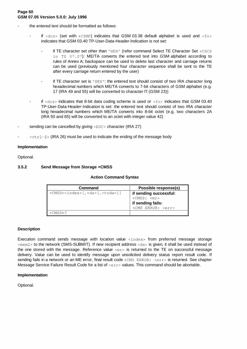
Page 60GSM 07.05 Version 5.0.0: July 1996
- the entered text should be formatted as follows:
- if <dcs> (set with +CSMP) indicates that GSM 03.38 default alphabet is used and <fo>indicates that GSM 03.40 TP-User-Data-Header-Indication is not set:
- if TE character set other than "HEX" (refer command Select TE Character Set +CSCSin TS 07.07 ): ME/TA converts the entered text into GSM alphabet according torules of Annex A; backspace can be used to delete last character and carriage returnscan be used (previously mentioned four character sequence shall be sent to the TEafter every carriage return entered by the user)
- if TE character set is "HEX" : the entered text should consist of two IRA character longhexadecimal numbers which ME/TA converts to 7-bit characters of GSM alphabet (e.g.17 (IRA 49 and 55) will be converted to character Π (GSM 23))
- if <dcs> indicates that 8-bit data coding scheme is used or <fo> indicates that GSM 03.40TP-User-Data-Header-Indication is set: the entered text should consist of two IRA characterlong hexadecimal numbers which ME/TA converts into 8-bit octet (e.g. two characters 2A(IRA 50 and 65) will be converted to an octet with integer value 42)
- sending can be cancelled by giving <ESC> character (IRA 27)
- <ctrl-Z> (IRA 26) must be used to indicate the ending of the message body
Implementation
Optional.
3.5.2 Send Message from Storage +CMSS
Action Command Syntax
Command Possible response(s)+CMSS=<index>[,<da>[,<toda>]] if sending successful:
+CMSS: <mr>if sending fails:+CMS ERROR: <err>
+CMSS=?
Description
Execution command sends message with location value <index> from preferred message storage<mem2> to the network (SMS-SUBMIT). If new recipient address <da> is given, it shall be used instead ofthe one stored with the message. Reference value <mr> is returned to the TE on successful messagedelivery. Value can be used to identify message upon unsolicited delivery status report result code. Ifsending fails in a network or an ME error, final result code +CMS ERROR: <err> is returned. See chapterMessage Service Failure Result Code for a list of <err> values. This command should be abortable.
Implementation
Optional.

Page 61GSM 07.05 Version 5.0.0: July 1996
3.5.3 Write Message to Memory +CMGW
Action Command Syntax
Command Possible response(s)if text mode ( +CMGF=1):+CMGW=<oa/da>[,<tooa/toda>[,<stat>]]<CR>text is entered <ctrl-Z/ESC>
+CMGW: <index>+CMS ERROR: <err>
+CMGW=?
Description
Execution command stores message (either SMS-DELIVER or SMS-SUBMIT) to preferred memorystorage <mem2>. Memory location <index> of the stored message is returned. By default messagestatus will be set to 'stored unsent', but parameter <stat> allows also other status values to be given.The entering of text is done similarly as specified in command Send Message +CMGS. If writing fails, finalresult code +CMS ERROR: <err> is returned. See chapter Message Service Failure Result Code for<err> values.
Implementation
Optional.
3.5.4 Delete Message +CMGD
Action Command Syntax
Command Possible response(s)+CMGD=<index> +CMS ERROR: <err>+CMGD=?
Description
Execution command deletes message from preferred message storage <mem1> location <index> . Ifdeleting fails, final result code +CMS ERROR: <err> is returned. See chapter Message Service FailureResult Code for <err> values.
Implementation
Optional.

Page 62GSM 07.05 Version 5.0.0: July 1996
3.5.5 Send Command +CMGC
Action Command Syntax
Command Possible response(s)if text mode ( +CMGF=1):+CMGC=<fo>,<ct>[,<pid>[,<mn>[,<da>[,<toda>]]]]<CR>text is entered <ctrl-Z/ESC>
if sending successful:+CMGC: <mr>if sending fails:+CMS ERROR: <err>
+CMGC=?
Description
Execution command sends a command message from a TE to the network (SMS-COMMAND). Theentering of text (GSM 03.40 TP-Command-Data) is done similarly as specified in command Send Message+CMGS, but the format is fixed to be a sequence of two IRA character long hexadecimal numbers whichME/TA converts into 8-bit octets (refer +CMGS). Message reference value <mr> is returned to the TE onsuccessful message delivery. Value can be used to identify message upon unsolicited delivery statusreport result code. If sending fails in a network or an ME error, final result code +CMS ERROR: <err> isreturned. See chapter Message Service Failure Result Code for a list of <err> values. This commandshould be abortable.
Implementation
Optional.

Page 63GSM 07.05 Version 5.0.0: July 1996
3.5.6 Informative Examples
Figure 4 is an example of a TE-TA-ME setup when messages are sent to network or stored to ME. Thevolatile memory may as well be in the ME, or a non-volatile memory may be used instead whenconstructing messages.
SM STORAGES
add text mode parameters (+CSMP)and SMSC address
ME TA TE
PDU mode send +CMGSand write +CMGW
text mode send +CMGSand write +CMGW
write +CMGW
send from storage +CMSS
SMS-SUBMIT
SMS-SUBMIT
write +CMGW
SMS-SUBMIT
(optionally addSMSC address)
in text mode, add SMSC address(optional in PDU mode)
send command +CMGCSMS-COMMAND
volatile memory
Figure 4: Message service send and write procedures
An example of sending a default alphabet message in text mode and a SMS-STATUS-REPORT is wanted:
AT+CNMI? (check that status reports are routed to TE)+CNMI: 2,1,0,1,0OKAT+CSMP=32,167,0,0 (status report wanted; otherwise default settings)OKAT+CMGS="+358501234567" (start editing a message)> This the first line. (edit first line and press carriage return)> This is the last line. ^Z (edit second line and send message by pressing control-Z)+CMGS: 10 (success: message reference 10 returned from SMSC)OK+CDS: 2,10,"+358501234567",145,"95/07/04/13:12:14+04","95/07/04/13:12:20+04",0 (status report of successful message delivery received)
Storing an unsent message in memory, sending it from there, and deleting it:
AT+CPMS? (check memory settings)+CPMS: "ME",4,10,"ME",4,10,"ME",4,10OKAT+CMGW="9501231234" (write message)> This is the message body ^Z+CMGW: 7 (index number in storage returned)OKAT+CMSS=7 (send from storage)+CMSS: 12 (success: reference value 12 sent from SC)OKAT+CMGD=7 (delete message)OK

Page 64GSM 07.05 Version 5.0.0: July 1996
4 PDU Mode
The PDU mode uses the same commands and responses as the Text Mode described in Section 3.However, the following commands and responses have a different format. In the PDU mode, a completeSMS Message including all header information is passed as a binary string. This binary string is composedof hexadecimal IA5 characters as defined in section 3 above under "Message Data Parameters".
4.1 List Messages +CMGL
Action Command Syntax
Command Possible response(s)+CMGL[=<stat>] if PDU mode ( +CMGF=0) and command successful:
+CMGL: <index>,<stat>,[<alpha>],<length><CR><LF><pdu>[<CR><LF>+CMGL:<index>,<stat>,[<alpha>],<length><CR><LF><pdu>[...]]otherwise:+CMS ERROR: <err>
+CMGL=? +CMGL: ( list of supported <stat> s)
Description
Execution command returns messages with status value <stat> from preferred message storage<mem1> to the TE. Entire data units <pdu> are returned. If status of the message is 'received unread',status in the storage changes to 'received read'. If listing fails, final result code +CMS ERROR: <err> isreturned. See chapter Message Service Failure Result Code for <err> values.
Test command shall give a list of all status values supported by the TA.
Implementation
Optional.
4.2 Read Message +CMGR
Action Command Syntax
Command Possible response(s)+CMGR=<index> if PDU mode ( +CMGF=0) and command successful:
+CMGR: <stat>,[<alpha>],<length><CR><LF><pdu>otherwise:+CMS ERROR: <err>
+CMGR=?
Description
Execution command returns message with location value <index> from preferred message storage<mem1> to the TE. Status of the message and entire message data unit <pdu> is returned. If status of themessage is 'received unread', status in the storage changes to 'received read'. If reading fails, final resultcode +CMS ERROR: <err> is returned. See chapter Message Service Failure Result Code for <err>values.
Implementation
Optional.

Page 65GSM 07.05 Version 5.0.0: July 1996
4.3 Send Message +CMGS
Action Command Syntax
Command Possible response(s)if PDU mode ( +CMGF=0):+CMGS=<length><CR>PDU is given <ctrl-Z/ESC>
if sending successful:+CMGS: <mr>if sending fails:+CMS ERROR: <err>
+CMGS=?
Description
Execution command sends message from a TE to the network (SMS-SUBMIT). Message reference value<mr> is returned to the TE on successful message delivery. Value can be used to identify message uponunsolicited delivery status report result code. If sending fails in a network or an ME error, final result code+CMS ERROR: <err> is returned. See chapter Message Service Failure Result Code for a list of <err>values. This command should be abortable.
- <length> must indicate the number of octets coded in the TP layer data unit to be given (i.e.SMSC address octets are excluded)
- the TA shall send a four character sequence <CR><LF><greater_than><space> (IRA 13, 10,62, 32) after command line is terminated with <CR>; after that PDU can be given from TE to ME/TA
- the DCD signal shall be in ON state while PDU is given
- the echoing of given characters back from the TA is controlled by V.25ter echo command E
- the PDU shall be hexadecimal format (similarly as specified for <pdu> ) and given in one line; ME/TAconverts this coding into the actual octets of PDU
- when the length octet of the SMSC address (given in the <pdu> ) equals zero, the SMSC addressset with command Service Centre Address +CSCA is used
- sending can be cancelled by giving <ESC> character (IRA 27)
- <ctrl-Z> (IRA 26) must be used to indicate the ending of PDU
Implementation
Optional.
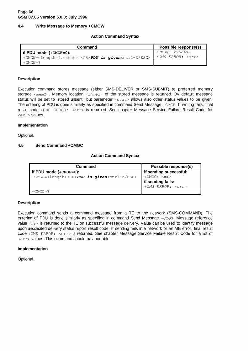
Page 66GSM 07.05 Version 5.0.0: July 1996
4.4 Write Message to Memory +CMGW
Action Command Syntax
Command Possible response(s)if PDU mode ( +CMGF=0):+CMGW=<length>[,<stat>]<CR> PDU is given <ctrl-Z/ESC>
+CMGW: <index>+CMS ERROR: <err>
+CMGW=?
Description
Execution command stores message (either SMS-DELIVER or SMS-SUBMIT) to preferred memorystorage <mem2>. Memory location <index> of the stored message is returned. By default messagestatus will be set to 'stored unsent', but parameter <stat> allows also other status values to be given.The entering of PDU is done similarly as specified in command Send Message +CMGS. If writing fails, finalresult code +CMS ERROR: <err> is returned. See chapter Message Service Failure Result Code for<err> values.
Implementation
Optional.
4.5 Send Command +CMGC
Action Command Syntax
Command Possible response(s)if PDU mode ( +CMGF=0):+CMGC=<length><CR>PDU is given <ctrl-Z/ESC>
if sending successful:+CMGC: <mr>if sending fails:+CMS ERROR: <err>
+CMGC=?
Description
Execution command sends a command message from a TE to the network (SMS-COMMAND). Theentering of PDU is done similarly as specified in command Send Message +CMGS. Message referencevalue <mr> is returned to the TE on successful message delivery. Value can be used to identify messageupon unsolicited delivery status report result code. If sending fails in a network or an ME error, final resultcode +CMS ERROR: <err> is returned. See chapter Message Service Failure Result Code for a list of<err> values. This command should be abortable.
Implementation
Optional.

Page 67GSM 07.05 Version 5.0.0: July 1996
Annex A (Normative): Character Set Conversions for SMS Text Mode
The following conversions to and from GSM 03.38 default alphabet are defined:
TE char set bits/char CommandsPC Code Page 437 8 +CMGF=1;+CSCS="PCCP437"
PC Danish/Norwegian 8 +CMGF=1;+CSCS="PCDN"
ISO 8859 Latin 1 8 +CMGF=1;+CSCS="8859-1"
IRA 7 +CMGF=1;+CSCS="IRA"
GSM default alphabet 7 +CMGF=1;+CSCS="GSM"
The tables below show which 7 bit GSM value corresponds to the 7 or 8 bit value of external characterset. The TE character set value is computed by adding column value, 00H through F0H (70H for 7bits/char), with the row value (00H through 0FH). All values are in hexadecimal, but the H suffix is not used.When text mode is implemented, it is mandatory for a TA to have at least one conversion which include theconversion table of IRA (e.g. PC Code Page 437 does). Additional conversions can be defined bymanufacturers. It is manufacturer specific if the TE set is actually converted to GSM set in the TA or in theME, and if the TE set is converted to a ME specific set in the TA before converting it to GSM set whenmessage is sent to the network. It is recommended that characters which cannot be converted to GSM setare deleted.
Conversion from IRA to GSM:
00 10 20 30 40 50 60 7000 - - 20 30 00 50 - 7001 - - 21 31 41 51 61 7102 - - 22 32 42 52 62 7203 - - 23 33 43 53 63 7304 - - 02 34 44 54 64 7405 - - 25 35 45 55 65 7506 - - 26 36 46 56 66 7607 - - 27 37 47 57 67 7708 - - 28 38 48 58 68 7809 - - 29 39 49 59 69 790A LF - 2A 3A 4A 5A 6A 7A0B - - 2B 3B 4B - 6B -0C - - 2C 3C 4C - 6C -0D CR - 2D 3D 4D - 6D -0E - - 2E 3E 4E - 6E -0F - - 2F 3F 4F - 6F -

Page 68GSM 07.05 Version 5.0.0: July 1996
Conversion from PCCP437 (PC-8 Code Page 437) to GSM:
00 10 20 30 40 50 60 70 80 90 A0 B0 C0 D0 E0 F000 - - 20 30 00 50 - 70 09 457 6111 - - - - -01 - - 21 31 41 51 61 71 7E 1D 6912 - - - 1E -02 - - 22 32 42 52 62 72 05 1C 6F13 - - - 13 -03 - - 23 33 43 53 63 73 611 6F8 7514 - - - - -04 - - 02 34 44 54 64 74 7B 7C 7D - - - 18 -05 - 5F 25 35 45 55 65 75 7F 08 5D - - - - -06 - - 26 36 46 56 66 76 0F 759 - - - - - -07 - - 27 37 47 57 67 77 092 06 - - - - - -08 - - 28 38 48 58 68 78 653 7910 60 - - - 12 -09 - - 29 39 49 59 69 79 654 5C - - - - 19 -0A LF - 2A 3A 4A 5A 6A 7A 04 5E - - - - 15 -0B - - 2B 3B 4B - 6B - 695 - - - - - - -0C - - 2C 3C 4C - 6C - 696 01 - - - - - -0D CR - 2D 3D 4D - 6D - 07 03 40 - - - - -0E - - 2E 3E 4E - 6E - 5B - - - - - - -0F - - 2F 3F 4F - 6F - 0E - - - - - - -
1 : â Ö a 2 : ç Ö Ç 3 : ê Ö e 4 : ë Ö e 5 : ï Ö i
6 : î Ö i 7 : É Ö E 8 : ô Ö o 9 : û Ö u 10 : ÿ Ö y
11 : á Ö a 12 : í Ö i 13 : ó Ö o 14 : ú Ö u
Conversion from PCDN (PC-8 Danish/ Norwegian) to GSM:
00 10 20 30 40 50 60 70 80 90 A0 B0 C0 D0 E0 F000 - - 20 30 00 50 - 70 09 457 6111 - - - - -01 - - 21 31 41 51 61 71 7E 1D 6912 - - - 1E -02 - - 22 32 42 52 62 72 05 1C 6F13 - - - 13 -03 - - 23 33 43 53 63 73 611 6F8 7514 - - - - -04 - - 02 34 44 54 64 74 7B 7C 7D - - - 18 -05 - 5F 25 35 45 55 65 75 7F 08 5D - - - - -06 - - 26 36 46 56 66 76 0F 759 - - - - - -07 - - 27 37 47 57 67 77 092 06 - - - - - -08 - - 28 38 48 58 68 78 653 7910 60 - - - 12 -09 - - 29 39 49 59 69 79 654 5C - - - - 19 -0A LF - 2A 3A 4A 5A 6A 7A 04 5E - - - - 15 -0B - - 2B 3B 4B - 6B - 695 0C - - - - - -0C - - 2C 3C 4C - 6C - 696 01 - - - - - -0D CR - 2D 3D 4D - 6D - 07 0B 40 - - - - -0E - - 2E 3E 4E - 6E - 5B - - - - - - -0F - - 2F 3F 4F - 6F - 0E - - - - - - -
1 : â Ö a 2 : ç Ö Ç 3 : ê Ö e 4 : ë Ö e 5 : ï Ö i
6 : î Ö i 7 : É Ö E 8 : ô Ö o 9 : û Ö u 10 : ÿ Ö y
11 : á Ö a 12 : í Ö i 13 : ó Ö o 14 : ú Ö u

Page 69GSM 07.05 Version 5.0.0: July 1996
Conversion from 8859-1 (ISO 8859 Latin 1) to GSM:
00 10 20 30 40 50 60 70 80 90 A0 B0 C0 D0 E0 F000 - - 20 30 00 50 - 70 - - - - 411 - 7F -01 - - 21 31 41 51 61 71 - - 40 - 412 5D 6121 7D02 - - 22 32 42 52 62 72 - - - - 413 4F13 6122 0803 - - 23 33 43 53 63 73 - - 01 - 414 4F14 6123 6F30
04 - - 02 34 44 54 64 74 - - 24 - 5B 4F15 7B 6F31
05 - - 25 35 45 55 65 75 - - 03 - 0E 4F16 0F 6F32
06 - - 26 36 46 56 66 76 - - - - 1C 5C 1D 7C07 - - 27 37 47 57 67 77 - - 5F - 09 - 0924 -08 - - 28 38 48 58 68 78 - - - - 455 0B 04 0C09 - - 29 39 49 59 69 79 - - - - 456 5517 05 060A LF - 2A 3A 4A 5A 6A 7A - - - - 457 5518 6525 7533
0B - - 2B 3B 4B - 6B - - - - - 458 5519 6526 7534
0C - - 2C 3C 4C - 6C - - - - - 499 5E 07 7E0D CR - 2D 3D 4D - 6D - - - - - 4910 5920 6927 7935
0E - - 2E 3E 4E - 6E - - - - - 4911 - 6928 -0F - - 2F 3F 4F - 6F - - - - 60 4912 1E 6929 7936
1 : À Ö A 2 : Á Ö A 3 : Â Ö A 4 : Ã Ö A 5 : È Ö E
6 : É Ö E 7 : Ê Ö E 8 : Ë Ö E 9 : Ì Ö I 10 : Í Ö I
11 : Î Ö I 12 : Ï Ö I 13 : Ò Ö O 14 : Ó Ö O 15 : Ô Ö O
16 : Õ Ö O 17 : Ù Ö U 18 : Ú Ö U 19 : Û Ö U 20 : Ý Ö Y
21 : á Ö a 22 : â Ö a 23 : ã Ö a 24 : ç Ö Ç 25 : ê Ö e
26 : ë Ö e 27 : í Ö i 28 : î Ö i 29 : ï Ö i 30 : ó Ö o
31 : ô Ö o 32 : õ Ö o 33 : ú Ö u 34 : û Ö u 35 : ý Ö y
36 : ÿ Ö y
Conversions from GSM default alphabet to above character sets are otherwise straightforward, but noconversions of the characters listed below tables are applied.

Page 70GSM 07.05 Version 5.0.0: July 1996
Annex B (Informative): Example of processing a data block
B.1 Example state diagrams for the block receiver
The state diagrams on the following two pages show how the receiver component at the block level couldwork. In this example the received octets are processed in two stages.
Stage 1 is a low level function which detects the unique start and end markers, and removes any stuffingoctets. The results of this stage are passed to stage 2. Any unexpected octet value after a DLE will beindicated as 'abort'.
Stage 2 assembles the message content and the BCS octets, using octets passed from stage 1 and the'start' and 'end' indications. A 'start' will always reset the process to state 1 from any state. An 'abort' willalways cause a return to state 0 where a 'start' will be awaited. When an 'end' is received in state 1, thefollowing two octets are checked as the BCS. If the BCS is correct, the message content is passed toanother stage of the receiver for processing of the message content.
B.2 Example of coding and decoding a data block
The last page of this annex shows the coding of an example message at a transmitter, and the decodingstages at a receiver which has the two stages of processing as described above.
In this example, the message content and the BCS both contain an octet with a value of 10 hex. Thereforethe message as transmitted over the interface has additional stuffing octets (00 hex) inserted after theseoctets. The receiver first detects the start and end markers, and removes the stuffing octets. Finally theBCS is checked.

Page 71GSM 07.05 Version 5.0.0: July 1996
any other octet
ETXNULSTX
DLE
DLE
any other octet n
0 000
octet = DLE
0
octet = n
'Abort ''End''Start '
1Wait for STX,
ETX or NUL
0Idle
STATE TRANSITIONS IN STAGE 1
Message blocks
Octets, w ith separate Start, End and Abort
indications.
Octets from the DTE/DCE
interface
STAGE 2STAGE 1
The block receiver can be considered as two stages. Stage 1 detects start and end markers, and removes stuf fing characters. Stage 2 assembles the received message and checks the BCS.
EXAMPLE STATE DIAGRAMS FOR THE BLOCK RECEIVER

Page 72GSM 07.05 Version 5.0.0: July 1996
No
Yes
'End'
octet'Abort'
'End'
octet'Abort'
'End''Abort'0
0
0
Block received
checksum= 0000 ?
00
'Start'1Reset buffer
Reset checksum
add octet to checksum
3Wait for 2nd
BCS octet
0 0
'Start'1Reset buffer
Reset checksum
add (octet x 256) to checksum
2Wait for 1stBCS octet
octet
1
store in buf fer
add octet to checksum
any other octet
'Start'
'Start'
Reset bufferReset checksum
1Reset buffer
Reset checksum
1assemble
octets
0Idle
STATE TRANSITIONS IN STAGE 2

Page 73GSM 07.05 Version 5.0.0: July 1996
Example of coding / decoding a message at the DTE/DCE interface
LSBMSBBCS
LSBMSBBCS
Check BCS
Output from receiver stage 2
Output from receiver stage 1
Detect start & end markers, and remove stuff ing octets
Insert stuf fing octets, and add start & end markers
Message as received
(no errors)
LSBMSBBCS
message content**
endmarker
startmarker
50H40H30H20HNUL00H
10H00H ETX03H
DLE10H
NUL00H
10HFFHSTX02H
DLE10H
10H00H 50H40H30H20H
10H00H 50H40H30H20H 10HFFH
LSBMSBBCS
* = stuf f ing octet
message content**
endmarker
startmarker
10H00H
50H40H30H20HNUL00H
50H40H30H20H
10H00H ETX03H
DLE10H
Message as t ransmit ted
Calculate BCS
BCS prepared
Example message to be sent
10HFFH
50H40H30H20H10H00H
NUL00H
10HFFHSTX02H
DLE10H
' End'' Start'
Message t ransferred over DTE/DCE interface

Page 74GSM 07.05 Version 5.0.0: July 1996
History
Document history
July 1996 Publication of Version 5.0.0
ISBN 2-7437-0825-5Dépôt légal : Juillet 1996