gstp-6 element 1 compendium of potential generic...
TRANSCRIPT

Prepared by N. Peinado Reference TEC-SGT/2013-008/NP Issue 1 Revision 1 Date of Issue 26-02-2012 Status Document Type Distribution
ESA UNCLASSIFIED – For Official Use
estec European Space Research
and Technology Centre Keplerlaan 1
2201 AZ Noordwijk The Netherlands
T +31 (0)71 565 6565 F +31 (0)71 565 6040
www.esa.int
GSTP-6 Element 1
Compendium of Potential Generic Technology Activities (SD7)
Activities intended to be initiated in 2014
Page 2/84
GSTP-6 E1 SD7 Compendium - 2014
Date 26-02-2012 Issue 1 Rev 1
ESA UNCLASSIFIED – For Official Use
Title
Issue 1 Revision 1
Author Date 26-02-2012
Approved by Date
Reason for change Issue Revision Date
Issue 1 Revision 1
Reason for change Date Pages Paragraph(s)

Page 3/84
GSTP-6 E1 SD7 Compendium - 2014
Date 26-02-2012 Issue 1 Rev 1
ESA UNCLASSIFIED – For Official Use
Table of contents:
1 INTRODUCTION ................................................................................................................................ 42 LIST OF ACTIVITIES ......................................................................................................................... 73 DESCRIPTION OF ACTIVITIES ........................................................................................................ 133.1 CORE ................................................................................................................................................................................ 133.1.1 TD 1- On-board Data Systems ....................................................................................................................................... 133.1.2 TD 2- Space System Software ........................................................................................................................................ 173.1.3 TD 3- Spacecraft Electrical Power ................................................................................................................................ 213.1.4 TD 4- Spacecraft Environment & Effects ...................................................................................................................... 253.1.5 TD 5- Space System Control ......................................................................................................................................... 283.1.6 TD 6- RF Payload and Systems ..................................................................................................................................... 313.1.7 TD 7- Electromagnetic Technologies and Techniques ................................................................................................. 363.1.8 TD 8- System Design & Verification ............................................................................................................................. 423.1.9 TD 9- Mission Operations and Ground Data Systems ................................................................................................. 473.1.10 TD 11- Space Debris ...................................................................................................................................................... 483.1.11 TD 12- Ground Station System & Networking.............................................................................................................. 533.1.12 TD 16- Optics ................................................................................................................................................................. 543.1.13 TD 17- Optoelectronics .................................................................................................................................................. 573.1.14 TD 19- Propulsion .......................................................................................................................................................... 583.1.15 TD 20- Structures & Pyrotechnics ................................................................................................................................ 593.1.16 TD 21- Thermal ..............................................................................................................................................................663.1.17 TD 23- EEE Components and quality .......................................................................................................................... 683.1.18 TD 24- Materials and Processes ....................................................................................................................................693.2 SAVOIR ............................................................................................................................................................................ 703.3 SPACE & ENERGY ........................................................................................................................................................... 74

Page 4/84
GSTP-6 E1 SD7 Compendium - 2014
Date 26-02-2012 Issue 1 Rev 1
ESA UNCLASSIFIED – For Official Use
1 INTRODUCTION
During the Council meeting at Ministerial level held in November 2012, the sixth Period of the GSTP (ESA/C(2012)199) was presented and extensively subscribed by the GSTP Participating States with the following framework: GSTP-6 Element 1 – Support Technology Activities for Projects and Industry GSTP-6 Element 2 – Competitiveness GSTP-6 Element 3 – Technology Flight Opportunities GSTP-6 Element 4 – Precise Formation Flying Demonstration Following the approval of this new GSTP Period, this document provides the first list of candidate activities to the Initial work Plan of the GSTP-6 Element 1, in line with the process and timeline described in the information note to September IPC ESA/IPC(2012)98 – Preparing the work plans for the GSTP-6 Element 1. As indicated in this referenced document, Technology development activities in ESA are organised in 9 service domains (SD) and 25 technology domains (TD). This first pre-selection corresponds to activities belonging to the Generic Domain, SD7, devoted to transversal technologies common to several other SD, and to exploitation of technology (r)- evolution. According to the ESA-wide technology E2E process described in ESA/IPC(2008)61 rev 1, the activities which are part of this compendium have been pre-selected following an intensive internal exercise started in October 2012 and which included programmatic screening, technical evaluation and consistency checking with technology strategy and THAG Roadmaps. In addition to the core activities which are dedicated to the development of technologies, building blocks and components for future space, three special areas have been identified whose activities are shown in these documents in separate sections:
CLEAN SPACE: This is an ESA cross-cutting initiative with the aim to contribute to the reduction of the environmental impact of space programmes, taking into account the overall life-cycle and the management of residual waste and pollution resulting from space activities. The list and descriptions of candidate activities for this special area is provided in a separate document.
SAVOIR: Space Avionics Open Interface aRchitecture. This is an initiative to
federate the space avionics community and to work together in order to improve the way that the European Space community builds avionics subsystems.
SPACE & ENERGY: This special area addresses open innovation, spin-in /out
and joint R&T as currently initiated under GSTP 5 with the overall goal of achieving a more sustainable, less-carbon intensive European energy sector.

Page 5/84
GSTP-6 E1 SD7 Compendium - 2014
Date 26-02-2012 Issue 1 Rev 1
ESA UNCLASSIFIED – For Official Use
This compendium is divided in two separate documents according to the intended initiating dates of the activities:
GSTP-6 Element 1 Compendium of Potential Generic Technology Activities (SD7) - Activities intended to be initiated in 2013. Includes a list and detailed description of 77 activities
GSTP-6 Element 1 Compendium of Potential Generic Technology Activities (SD7) - Activities intended to be initiated in 2014–Includes a list and detailed description of 63 activities. (Present document)
This compendium is issued to Delegations of GSTP-6 Participating States and their industries for comments. Such comments will be considered in establishing the initial work plan for this GSTP 6 Element 1. The objective is to have a good indication of the developments GSTP Participating States may consider to support in order to present the GSTP-6 Element 1 Initial Work Plan with a consolidated set of activities to the IPC in May 2013 and the corresponding Procurement Plan to the IPC in June 2013 for approval.

Page 6/84
GSTP-6 E1 SD7 Compendium - 2014
Date 26-02-2012 Issue 1 Rev 1
ESA UNCLASSIFIED – For Official Use
Page 7/84
GSTP-6 E1 SD7 Compendium - 2014
Date 26-02-2012 Issue 1 Rev 1
ESA UNCLASSIFIED – For Official Use
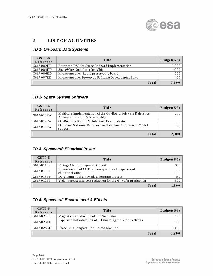
2 LIST OF ACTIVITIES
TD 1- On-board Data Systems
GSTP-6 Reference
Title Budget(K€)
G617-002ED European DSP for Space Radhard Implementation 6,000G617-004ED SpaceWire Node Interface Chip 1,000G617-006ED Microcontroller Rapid prototyping board 200G617-007ED Microcontroller Prototype Software Development Suite 400
Total 7,600
TD 2- Space System Software
GSTP-6 Reference
Title Budget(K€)
G617-010SW Multicore implementation of the On-Board Software Reference Architecture with IMA capability. 500
G617-012SW On-Board Software Architecture Demonstrator 800
G617-013SW On Board Software Reference Architecture Component Model support
800
Total 2,100
TD 3- Spacecraft Electrical Power
GSTP-6 Reference
Title Budget(K€)
G617-014EP Voltage Clamp Integrated Circuit 350
G617-016EP Enhancement of COTS supercapacitors for space and characterisation
300
G617-018EP Development of a new glass forming process 150G617-019EP Yield increase and cost reduction for the 6'' wafer production 500
Total 1,300
TD 4- Spacecraft Environment & Effects
GSTP-6 Reference Title Budget(K€)
G617-021EE Magnetic Radiation Shielding Simulator 400
G617-023EE Experimental validation of 3D shielding tools for electrons
500
G617-025EE Phase C/D Compact Hot Plasma Monitor 1,400
Total 2,300

Page 8/84
GSTP-6 E1 SD7 Compendium - 2014
Date 26-02-2012 Issue 1 Rev 1
ESA UNCLASSIFIED – For Official Use
TD 5- Space System Control
GSTP-6 Reference
Title Budget(K€)
G617-031EC Micro Miniature Star Tracker 1,400G617-032EC 2nd Generation APS Star Tracker 2,500G617-033EC Advanced Reaction Wheel 1,750
Total 5,650
TD 6- RF Payload and Systems
GSTP-6 Reference
Title Budget(K€)
G617-039ET Assessment of non-hermetic packaging for on-board RF equipment 800G617-041ET A small foot print lightweight GaN SSPA for TWT replacement in
satellite payloads. 1,000
G617-042ET Critical materials for Traveling Wave Tubes 1,200G617-043ET Fully Analogue on-board Receiver EM Development for TT&C
applications 600
G617-045ET GNSS Software-defined Space Receiver 600
Total 4,200
TD 7- Electromagnetic Technologies and Techniques
GSTP-6 Reference
Title Budget(K€)
G617-046EE Scattering analysis by surface current mapping utilizing NF scanners with contactless antenna surface profile measurement instrumentation.
300
G617-048EE Testing of passive inter-modulation (PIM) products using antenna Near-Field testing approaches
450
G617-049EE Flat petals compact unfurlable antenna for small satellites 600G617-050EE THz Testing Facility Development 500G617-053EE Qualification of novel grounding for composite structural panels 1,000
Total 2,850

Page 9/84
GSTP-6 E1 SD7 Compendium - 2014
Date 26-02-2012 Issue 1 Rev 1
ESA UNCLASSIFIED – For Official Use
TD 8- System Design & Verification
GSTP-6 Reference
Title Budget(K€)
G617-057SW Exchange of Engineering Data Between System and Sub-System Levels
450
G617-058SW Applying the FAMOUS concept to implement the ECSS-E-TM-10-23A space system data repository - information modelling - methodology and tool
1,500
G617-059SW Improvement of integration and verification activities 600G617-060SW Rationalisation and qualification of simulator tools 800
Total 3,350
TD 9- Mission Operations and Ground Data Systems
GSTP-6 Reference
Title Budget(K€)
G617-063GI Demonstrator of next generation M&C protocol for space systems 300
Total 300
TD 11- Space Debris
GSTP-6 Reference
Title Budget(K€)
G617-069GR Ground-based observations deriving attitude and attitude rate information
250
G617-070GR Feasibility of CMOS on-chip processing algorithms for space debris observations
300
G617-071GR Low thrust manoeuvres in orbit determination tools 150G617-072GR Advanced re-entry break-up high- and low-fidelity assessment
software 300
Total 1,000
TD 12- Ground Station System & Networking
GSTP-6 Reference
Title Budget(K€)
G617-135GS Low Cost Meter-Class Adaptive Optics Communications Terminal 800
Total 800

Page 10/84
GSTP-6 E1 SD7 Compendium - 2014
Date 26-02-2012 Issue 1 Rev 1
ESA UNCLASSIFIED – For Official Use
TD 16- Optics
GSTP-6 Reference
Title Budget(K€)
G617-084MM Demonstrator for active WFE-correction of an imaging telescope 1,000G617-091MM Optical components based on high-efficiency Volume Bragg
Gratings 300
Total 1,300
TD 17- Optoelectronics
GSTP-6 Reference Title Budget(K€)
G617-093MM Vacuum chamber technologies for Atom Interferometry applications
800
Total 800
TD 19- Propulsion
GSTP-6 Reference
Title Budget(K€)
G617-098MP High Power (5 kW) HEMPT (Highly Efficiency Multistage Plasma Thruster)
1,000
Total 1,000
TD 20- Structures & Pyrotechnics
GSTP-6 Reference
Title Budget(K€)
G617-102MS Improvement of industrial approach for design and verification of non-linear spacecraft structures
500
G617-103MS Advanced CFRP assemblies for spacecraft bus and payload module platforms.
600
G617-105MS Fibre Steering 750G617-109MS Reshaping of Antenna and Telescope Reflectors 700
Total 2,550

Page 11/84
GSTP-6 E1 SD7 Compendium - 2014
Date 26-02-2012 Issue 1 Rev 1
ESA UNCLASSIFIED – For Official Use
TD 21- Thermal
GSTP-6 Reference
Title Budget(K€)
G617-113MT Extended in-flight validation of LHP modelling methods 150
G617-114MT Heat Pump Conceptual Design and Breadboard testing 600
Total 750
TD 23- EEE Components and quality
GSTP-6 Reference
Title Budget(K€)
G617-117QT ESCC Evaluation and Qualification of a monolithic magnetometer based on Micro Technology
600
Total 600
TD 24- Materials and Processes
GSTP-6 Reference Title Budget(K€)
G617-129QT Development of Improved Bonding and Repairs for OSRs 600
Total 600
Specific area: SAVOIR
GSTP-6 Reference
Title Budget(K€)
G61V-002SW AES/SAVOIR: IMA-SP Execution Platform partition kernel qualification
500
G61V-003ED AES/SAVOIR: Consolidation of Specification of Modular RTU Modules (electrical, mechanical and thermal interfaces)
200
G61V-004SW AES/SAVOIR: IMA-SP Execution Platform Consolidation and Industrialisation
1,000
Total 1,700

Page 12/84
GSTP-6 E1 SD7 Compendium - 2014
Date 26-02-2012 Issue 1 Rev 1
ESA UNCLASSIFIED – For Official Use
Specific area: Space & Energy
GSTP-6 Reference
Title Budget(K€)
G61E-001EP Space&Energy: Life testing of solar cells for space and terrestrial applications
500
G61E-002MT Space&Energy: Heat Storage for Terrestrial Application 400G61E-003MT Space&Energy: Thermal Insulation for Buildings & Industrial
Processes 500
G61E-004MT Space&Energy: Loop Heat Pipes for Heat Recovery & Solar Power Conversion
200
G61E-005MT Space&Energy: Heat Pipes for Batteries & Fuel Cells 600G61E-006EE Space&Energy: Prototype of space weather services to drilling and
surveying activities of the European energy industrial sector 1,000
G61E-007MM Space&Energy: BIOFUEL 500G61E-008MM Space&Energy: EnRUM (energetic ressources utilisation map) 400G61E-009MT Space&Energy: Cryogenic Composite Tanks - Light-Weight Long-
Term Hydrogen Storage 400
G61E-010MT Space&Energy: Slush hydrogen - up-scaling and optimising production
600
G61E-011MT Space&Energy: Slush Natural Gas (SLNG) Production 300
Total 5,400

Page 13/84
GSTP-6 E1 SD7 Compendium - 2014
Date 26-02-2012 Issue 1 Rev 1
ESA UNCLASSIFIED – For Official Use
3 DESCRIPTION OF ACTIVITIES
3.1 CORE
3.1.1 TD 1- On-board Data Systems
Core / Specific Areas
CORE
Technology Domain
1 On-board Data Systems
Ref. Number: G617-002ED Budget (k€):
6000
Title: European DSP for Space Radhard Implementation Objectives: Hardening and adaptation of the commercial DSP IP-core (AD21469),
manufacturing of ASIC prototypes on 65nm technology, validation and industrialization of European DSP components
Description: Digital Signal Processors (DSP) provide a high data throughput combined with a high number of fixed or floating point operations. Their internal architecture is optimised to allow highly efficient execution of signal processing algorithms, fast data transfer and a high data throughput at very low power consumption. This makes them the ideal component to handle, filter and compress streams of payload data or run fast control loops or other complex processing functions in many types of equipment including platform subsystems, payload data processors, instruments, and others. About 15 years ago ESA has undertaken to port the ADSP21020 DSP from the US to radiation tolerant technology for space. This device was an enabling technology at the time which was widely used in a large range of space applications and it still can be found in some legacy equipment today. The component is now obsolete and coming to its end of life. The reason for the success of this Space DSP which is based on the spin-in of widely used commercial DSP technology was that it made high end processing power easily accessible to a wide range of equipment, instrument and subsystem manufactures. Together with the readily available and widely used commercial Software Development Environment and Process it reduced the development time and cost of new on board equipment and applications. The component was commercially very successful and both components and derived equipment was sold world-wide by European industry. The development of the new European DSP for Space Application shall follow the same lines but it will be based on a high-end commercial DSP design and be implemented on the latest (65nm) silicon technology for space. It shall provide a processing power of > 1 GFlops at very low power consumption. In this activity the IP-core of the commercial DSP will be hardened and the interfaces will be adapted to the specific space needs while ensuring full compatibility with the commercial software development process and tools. The device will be manufactured and validated.
Deliverables: Validated DSP Component
Current TRL: 4 Target TRL: 5 Duration (months) 36
Applicable THAG Roadmap: On-Board Payload Data Processing (2011)

Page 14/84
GSTP-6 E1 SD7 Compendium - 2014
Date 26-02-2012 Issue 1 Rev 1
ESA UNCLASSIFIED – For Official Use
Core / Specific Areas
CORE
Technology Domain
1 On-board Data Systems
Ref. Number: G617-004ED Budget (k€):
1000
Title: SpaceWire Node Interface Chip Objectives: Design, development, implementation and validation of SpaceWire Node Interface
Chip ASIC prototypes in current radiation tolerant silicon technology.
Description: SpaceWire has gained popularity in the past years and is now proposed for almost every new ESA mission. This success is also due to the availability of a number of key components which have been developed in the past under ESA contract. The silicon technology used for some of these components is now obsolete and the current need is supplied from the available stock of components. To prevent a shortage a new generation of devices needs to be developed and manufactured in current silicon technology for space. This in particular the case for the node and instrument interface chips SMCS116SpW and SMCS332SpW which were the first type of SpaceWire component developed. The new generation of SpaceWire Node Interface Chip shall simplify the implementation of a SpaceWire interface for instrument developers and also support the SpaceWire protocols which have been developed in the mean time like RMAP, SpW-D, Time Distribution Protocol and PnP.
Deliverables: Prototype
Current TRL: 3 Target TRL: 4 Duration (months)
24
Applicable THAG Roadmap: On-Board Payload Data Processing (2011)

Page 15/84
GSTP-6 E1 SD7 Compendium - 2014
Date 26-02-2012 Issue 1 Rev 1
ESA UNCLASSIFIED – For Official Use
Core / Specific Areas
CORE
Technology Domain
1 On-board Data Systems
Ref. Number: G617-006ED Budget (k€): 200
Title: Microcontroller Rapid prototyping board Objectives: To develop a prototype board for the new mixed microcontroller (TRP activity
T701-307ED)
Description: The Activity TRP 701-317ED developed a Microcontroller. The digital part of this Microcontroller is based either on a LeonX based Core or on commercial/embedded digital core ( e.g. ARM, XAP, ...). In both the two cases a new or deeply modified Software developent suite is necessary to be able to program, control and aceess to new or modified elements of the microcontroller. Besides the Instruction Set Simulator other elements of the Microcontroller Prototype SW Development suite will be: a) A debugging tool is critical to speed up the software development and validation. GNU debugger tools like GDB running on host are usually the preferred choice. The development or the adaptation of a low cost, GDB compatible, non intrusive debug monitor software shall be the preferred solution b)The possibility to implement an API driven approach for microcontroller coding shall be investigated. A standard way to access the Microcontroller peripherals need to be created and tested. A qualified hardware abstraction layer library to provide simple APIs to peripherals and specific processor. c) Real time applications involving Microcontrollers often require managing the concurrency of multiple tasks. In these cases the use of a real time kernel brings benefits in terms of predictability, portability, code reuse, easier testing etc. Due to the limited memory space a suitable kernel could be just a scheduler implementing the minimum features to support dinamic schedule and switch between tasks or a more complex kernel (like the FreeRTOS kernel) implementing also basic concurrency primitives like events, semaphores, queues. The following tasks will be performed accurately checked through reviews: Requirements definition and analysis , Definition of an architecure of the SW development suite, development and validation of the SW development suite.
Deliverables: Prototype
Current TRL: 2 Target TRL: 4 Duration (months)
12
Applicable THAG Roadmap: Data Systems and On-Board Computers (2011)
Page 16/84
GSTP-6 E1 SD7 Compendium - 2014
Date 26-02-2012 Issue 1 Rev 1
ESA UNCLASSIFIED – For Official Use
Core / Specific Areas
CORE
Technology Domain
1 On-board Data Systems
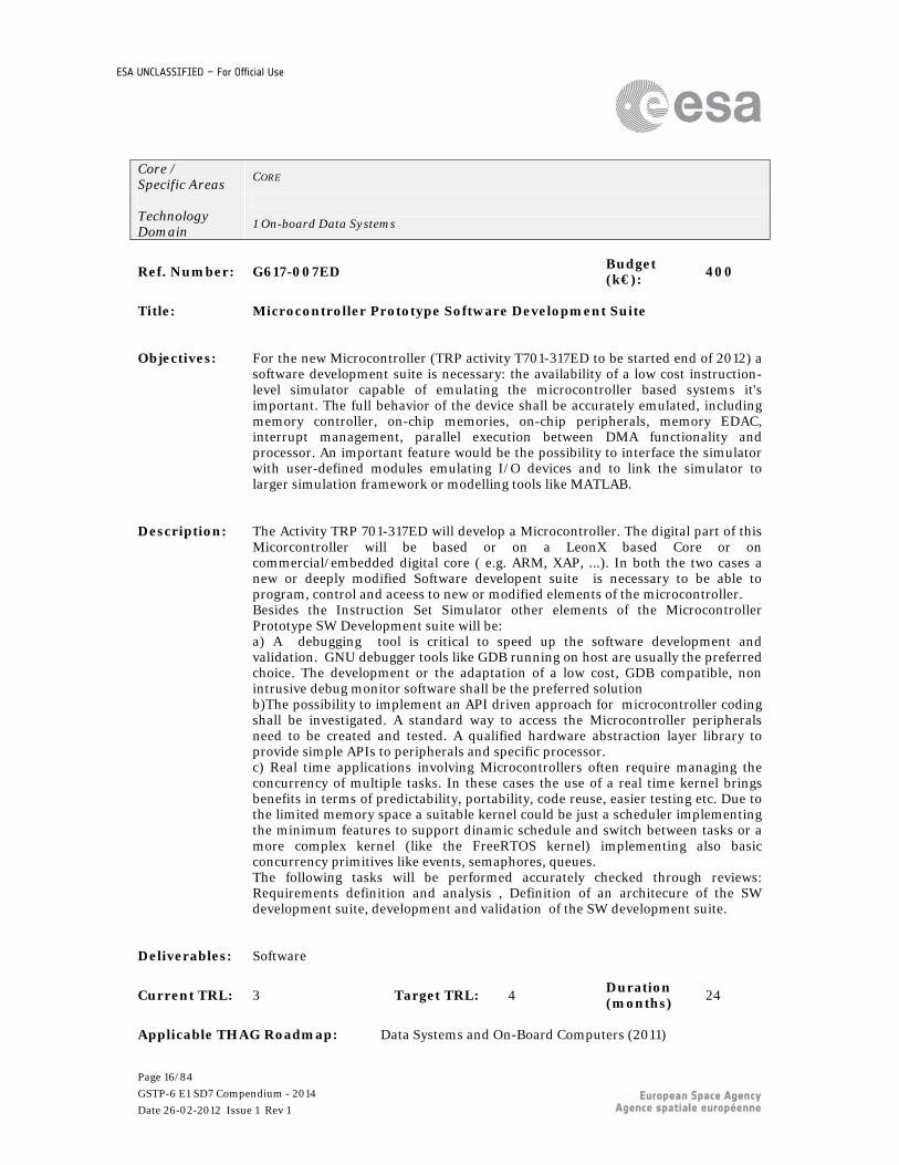
Ref. Number: G617-007ED Budget (k€): 400
Title: Microcontroller Prototype Software Development Suite
Objectives: For the new Microcontroller (TRP activity T701-317ED to be started end of 2012) a
software development suite is necessary: the availability of a low cost instruction-level simulator capable of emulating the microcontroller based systems it's important. The full behavior of the device shall be accurately emulated, including memory controller, on-chip memories, on-chip peripherals, memory EDAC, interrupt management, parallel execution between DMA functionality and processor. An important feature would be the possibility to interface the simulator with user-defined modules emulating I/O devices and to link the simulator to larger simulation framework or modelling tools like MATLAB.
Description: The Activity TRP 701-317ED will develop a Microcontroller. The digital part of this Micorcontroller will be based or on a LeonX based Core or on commercial/embedded digital core ( e.g. ARM, XAP, ...). In both the two cases a new or deeply modified Software developent suite is necessary to be able to program, control and aceess to new or modified elements of the microcontroller. Besides the Instruction Set Simulator other elements of the Microcontroller Prototype SW Development suite will be: a) A debugging tool is critical to speed up the software development and validation. GNU debugger tools like GDB running on host are usually the preferred choice. The development or the adaptation of a low cost, GDB compatible, non intrusive debug monitor software shall be the preferred solution b)The possibility to implement an API driven approach for microcontroller coding shall be investigated. A standard way to access the Microcontroller peripherals need to be created and tested. A qualified hardware abstraction layer library to provide simple APIs to peripherals and specific processor. c) Real time applications involving Microcontrollers often require managing the concurrency of multiple tasks. In these cases the use of a real time kernel brings benefits in terms of predictability, portability, code reuse, easier testing etc. Due to the limited memory space a suitable kernel could be just a scheduler implementing the minimum features to support dinamic schedule and switch between tasks or a more complex kernel (like the FreeRTOS kernel) implementing also basic concurrency primitives like events, semaphores, queues. The following tasks will be performed accurately checked through reviews: Requirements definition and analysis , Definition of an architecure of the SW development suite, development and validation of the SW development suite.
Deliverables: Software
Current TRL: 3 Target TRL: 4 Duration (months)
24
Applicable THAG Roadmap: Data Systems and On-Board Computers (2011)

Page 17/84
GSTP-6 E1 SD7 Compendium - 2014
Date 26-02-2012 Issue 1 Rev 1
ESA UNCLASSIFIED – For Official Use
3.1.2 TD 2- Space System Software
Core / Specific Areas
CORE
Technology Domain
2 Space System Software
Ref. Number: G617-010SW Budget (k€):
500
Title: Multicore implementation of the On-Board Software Reference
Architecture with IMA capability. Objectives: The works performed by Savoir-Faire, Savoir-IMA and the related industrial
activities have not investigated the particular use of a multicore in the hardware topology. The architectural principles are indeed modular enough to minimize the impacts of the use of a new type of processors. Using a multicore in this scope is feasible. But specific aspects need to be investigated: - insertion of a new hardware concept in the Space Component Model ("core") and its position with respect to a mono-processor or a partition, in particular the relationship partition/core. - refinement of the notion of deployment of components on cores in addition to partitions. - impact of multicore on the execution platform. Major impacts are expected in the notion of inter-partition or inter-core communication, and on the scheduling of partitions on cores. The determinism of the real-time behaviour of Time partitioning is impacted by a multicore behavior.
Description: The activity includes: 1) theoretical study on the relationship between partitioning and multicore. Analysis of the overheads and lack of determinisms of multicore (and in particular the NGMP) on the Time and Space partictioning concept. Analysis of the mapping partition/core (1 to 1, several partition on a core, 1 partition across cores) 2) Evolution of the Space Component Model to allow the expression of multi-cores in the hardware topology. 3) evolution of the execution platform to support TSP and multicore 3) evolution of the tools to deploy the components on multicore hardware with the updated execution platform. 4) case study on the Estec avionics test bench.
Deliverables: Software
Current TRL: 3 Target TRL: 4 Duration (months)
18
Applicable THAG Roadmap: On-Board Software (2010)

Page 18/84
GSTP-6 E1 SD7 Compendium - 2014
Date 26-02-2012 Issue 1 Rev 1
ESA UNCLASSIFIED – For Official Use
Core / Specific Areas
CORE
Technology Domain
2 Space System Software
Ref. Number: G617-012SW Budget (k€): 800
Title: On-Board Software Architecture Demonstrator Objectives: Ultimate result of the Savoir-Faire, Savoir-IMA, and industrial activities supporting
the on-board software reference architecture, the activity objective is to demonstrate the correctness of the software reference architecture concepts in a full on-board software use case. Starting from various prototype available from different studies (COrDets, OSRAC, OBCP, IMA4Sp, etc), the activity aims at producing a representative on-board software featuring the usual on-board functions, and produced following the process and architecture of Savoir. This activity is also preparatory for small missions aiming at in-orbit demonstration (IOD) of new mission techniques and architectures and system concepts as well as of new approaches for their development, verification and operation.
Description: This includes: - Identification or development of a qualified set of library modules implementing the execution platform services (PUS services, SOIS layers, OBCP interpretor, operating systems, with and without TSP, etc). - Integrating the modules consistently into the Execution platform of the software reference architecture. - Definition of application components, possibly following functional chains generic specification. - Integration of the application components in the architecture following the development approach described in the software reference architecture process, therefore configuring the execution platform to the needs of the application. Production of a demonstrator. In order to make the study affordable, several existing prototype elements may be reused from COrDet (some PUS and SOIS elements for EagleEye of the Estec laboratory), from OSRAC (some functional chain components), from OBCP (a LUA interpretor), from IMA4Sp (partitioning of EagleEye, Xtratum, RTEMS). For EagleEye, an Avionics test bench exists at Estec for validation of the software.
Deliverables: Software
Current TRL: 3 Target TRL: 5 Duration (months)
18
Applicable THAG Roadmap: On-Board Software (2010)

Page 19/84
GSTP-6 E1 SD7 Compendium - 2014
Date 26-02-2012 Issue 1 Rev 1
ESA UNCLASSIFIED – For Official Use
Core / Specific Areas
CORE
Technology Domain
2 Space System Software
Ref. Number: G617-013SW Budget (k€): 800
Title: On Board Software Reference Architecture Component Model support Objectives: Under the umbrella of Savoir-Faire, the several COrDeT/OSRAC activities are
consolidating the reference architecture principles, in particular the execution platform services. A Space Component Model is being defined as a prototype meta model. A prototype development tool chain is also available. Savoir-Faire has defined a related strategy, while Savoir-IMA has defined the needs of IMA in the Reference Architecture. This activity intends to support the two working groups further. The objectives of the activity are: 1) Clean-up and finalize the Space Component Model in terms of meta model combined with an english text describing its semantic. 2) Support the scenario 1.b.2 which has been discussed by Savoir-Faire, i.e. avail support to use the Space Component Model either as a native metamodel with an editor, or as an equivalent UML profile with a UML tool. 3) Support the IMA architecture to refine the processes, methods (including model based design), roles and tools for the effective deployment of the IMA-SP approach to spacecraft avionics in the scope of the Reference Architecture. 4) Consolidate the interface with avionics modelling techniques at the level of the deployment view/physical description of the hardware platform, including the busses (e.g. 1553) and links (e.g. SpW) deployment. 5) Prepare interaction with the open source tool community such as Polarsys, investigation of open source tools such as Graphiti, Acceleo, potentially ObeoDesigner, etc.
Description: The activity shall include: 1a) The production of a solid, consistent, complete and efficient Space Component Model (SCM) from the existing prototype, expressed in meta-modelling technology. 1b) The production of a document explaining how to use the meta model, for each use case, supported by an example of design patterns or use case. This document can be seen also as a specification of a tool supporting the modelling. The document is also used to check the equivalence with a UML profile. 2) The production by model transformation of a UML model (e.g. based on Marte, Chess, etc) strictly equivalent to the SCM, such as a model described in the SCM can be translated into the UML profile and the opposite. 3) Integrate the tools developed in a previous TRP to enable the IMA System Architect to model the system in order to perform system design and allocate and optimise the use of the available resources, including the CPU time and I/O for each partition. 4) Integrate the avionics modelling techniques developed in a previous TRP to allow the avionics architect to check the hardware and busses performance. The outputs from these tasks shall be installed and demonstrated within the ESTEC Avionics Lab

Page 20/84
GSTP-6 E1 SD7 Compendium - 2014
Date 26-02-2012 Issue 1 Rev 1
ESA UNCLASSIFIED – For Official Use
Deliverables: Software
Current TRL: 3 Target TRL: 5 Duration (months)
18
Applicable THAG Roadmap: On-Board Software (2010)

Page 21/84
GSTP-6 E1 SD7 Compendium - 2014
Date 26-02-2012 Issue 1 Rev 1
ESA UNCLASSIFIED – For Official Use
3.1.3 TD 3- Spacecraft Electrical Power
Core / Specific Areas
CORE
Technology Domain
3 Spacecraft Electrical Power
Ref. Number: G617-014EP Budget (k€):
350
Title: Voltage Clamp Integrated Circuit Objectives: Development of voltage clamp integrated circuit to be used in power conversion
and distribution architectures based on Point of Load (or linear) regulators.
Description: To control over voltage emissions coming from failures or SEE in power conversion and distribution architectures based on Point of Load (or linear) regulators, it has been proposed by ESA to use a voltage clamp device in combination with a overcurrent limiter (different presentations in ESTEC, at the ESPC 2011 and in a running TRP study). The combination of the current limitation and the voltage clamp devices gives the chance to resolve the failure management within the architecture in a recurrent mode, based on real building blocks that can be recurrently sold by the relevant manufacturer with clear reliability, reproducibility and possibly cost advantages for the equipment manufacturer and at system level. The present activity consists in the design and development of the voltage clamp based on integrated technology (monolithic or other techology allowing similar packaging density). The development consists in the following main tasks: 1. Specification consolidation, based on technology limitations versus required size of the device and relevant thermal constraints; 2. Design 3. Manufacturing 4. Test validation.
Deliverables: Engineering Model
Current TRL: 3 Target TRL: 5 Duration (months) 18
Applicable THAG Roadmap: Power Management and Distribution (2008)

Page 22/84
GSTP-6 E1 SD7 Compendium - 2014
Date 26-02-2012 Issue 1 Rev 1
ESA UNCLASSIFIED – For Official Use
Core / Specific Areas
CORE
Technology Domain
3 Spacecraft Electrical Power
Ref. Number: G617-016EP Budget (k€): 300
Title: Enhancement of COTS supercapacitors for space and characterisation Objectives: To adapt COTS supercapacitors for space applications requiring high power
Description: COTS Supercapacitors will be adaptated to comply with space requirements for
missions requiring high power (i.e radar, lidars...) and in line with outcome of previous ESA study ("Evaluation of supercapacitors and impacts at system level"). In a first phase the most promising COTS supercapacitor will be selected, changes to be made to meet space requirements will be evaluated (packaging modification, sealing...) In a second phase, a module will be designed, manufactured and tested: electrical, mechanical tests and life tests. The balancing system will also be studied and implemented in the module.
Deliverables: Other: Supercapacitors module and associated data pack
Current TRL: 4 Target TRL: 6 Duration (months)
18
Applicable THAG Roadmap: Electrochemical Energy Storage (2010)
Page 23/84
GSTP-6 E1 SD7 Compendium - 2014
Date 26-02-2012 Issue 1 Rev 1
ESA UNCLASSIFIED – For Official Use
Core / Specific Areas
CORE
Technology Domain
3 Spacecraft Electrical Power
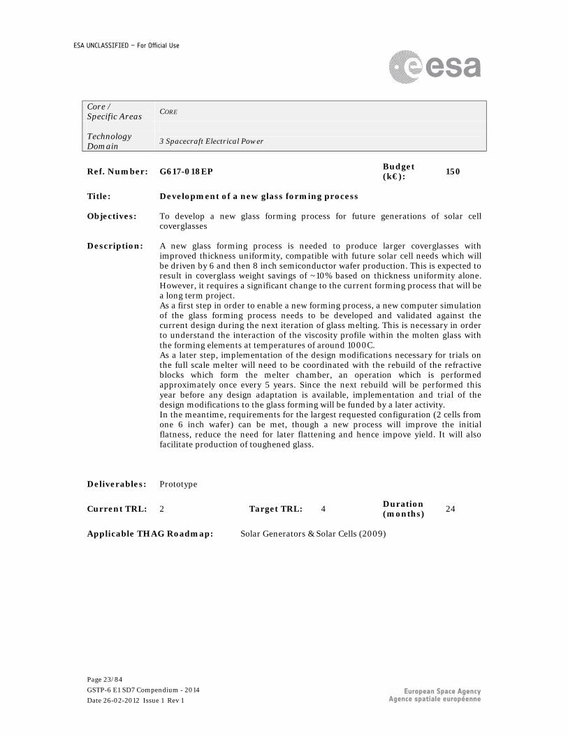
Ref. Number: G617-018EP Budget (k€): 150
Title: Development of a new glass forming process Objectives: To develop a new glass forming process for future generations of solar cell
coverglasses
Description: A new glass forming process is needed to produce larger coverglasses with improved thickness uniformity, compatible with future solar cell needs which will be driven by 6 and then 8 inch semiconductor wafer production. This is expected to result in coverglass weight savings of ~10% based on thickness uniformity alone. However, it requires a significant change to the current forming process that will be a long term project. As a first step in order to enable a new forming process, a new computer simulation of the glass forming process needs to be developed and validated against the current design during the next iteration of glass melting. This is necessary in order to understand the interaction of the viscosity profile within the molten glass with the forming elements at temperatures of around 1000C. As a later step, implementation of the design modifications necessary for trials on the full scale melter will need to be coordinated with the rebuild of the refractive blocks which form the melter chamber, an operation which is performed approximately once every 5 years. Since the next rebuild will be performed this year before any design adaptation is available, implementation and trial of the design modifications to the glass forming will be funded by a later activity. In the meantime, requirements for the largest requested configuration (2 cells from one 6 inch wafer) can be met, though a new process will improve the initial flatness, reduce the need for later flattening and hence impove yield. It will also facilitate production of toughened glass.
Deliverables: Prototype
Current TRL: 2 Target TRL: 4 Duration (months)
24
Applicable THAG Roadmap: Solar Generators & Solar Cells (2009)

Page 24/84
GSTP-6 E1 SD7 Compendium - 2014
Date 26-02-2012 Issue 1 Rev 1
ESA UNCLASSIFIED – For Official Use
Core / Specific Areas
CORE
Technology Domain
3 Spacecraft Electrical Power
Ref. Number: G617-019EP Budget (k€): 500
Title: Yield increase and cost reduction for the 6'' wafer production Objectives: Cost reduction and reliability improvement of 6'' Ge wafer prodcuction
Description: A critical process step in the wafer production is the cutting process of the
Germanium ingot; the initial thickness of the wafers after this cutting process as well as the kerf loss are basic parameters that influence the final yield - the smaller the initial thickness and the kerf loss the higher the number of wafers per ingot and the higher the potential yield. As a result wafer costs can be significantly reduced. Once a stable 6'' wafer production has been established, it is required to perform this process improvement and cost reduction exercise. The activity will include the following tasks: - reducing the distance between the wires of the wire saw to get thinner but more wafers from one ingot. - reducting the thickness of the wires of the wire saw and/or the size of the particles in the slurry basically performing the cutting which aims for reducing the kerf loss. Both improvements need to be carefully optimised especially by maintaining compatibility with subsequent process steps and the yield by avoiding increased breakage. Finally, also the quality of the wafer characteristics need to be maintained which will require adaptation of all process steps to the reduced initial thickness of the wafer. Another task is to optimise the recycling processes of the Ge material which is wasted along the different process steps from ingot to final wafer.
Deliverables: Engineering Model
Current TRL: 4 Target TRL: 5 Duration (months)
18
Applicable THAG Roadmap: Solar Generators & Solar Cells (2009)
Page 25/84
GSTP-6 E1 SD7 Compendium - 2014
Date 26-02-2012 Issue 1 Rev 1
ESA UNCLASSIFIED – For Official Use
3.1.4 TD 4- Spacecraft Environment & Effects
Core / Specific Areas
CORE
Technology Domain
4 Spacecraft Environment & Effects
Ref. Number: G617-021EE Budget (k€):
400
Title: Magnetic Radiation Shielding Simulator Objectives: Develop generic computational tools, methods and standards for simulating the
shielding properties of natural magnetic fields (e.g. geomagnetic "cut-off" at Earth, effects of Ganymede field on Jupiter environment), and artificial fields, against high energy charged particle radiation.
Description: Planetary magnetic fields provide shielding against high energy charged particles close to the primary body by deflecting the particles. At Earth this "geomagnetic shielding" results in cosmic rays and solar particle "cut-offs" that are characterised by vertical cut-off rigidity maps. The effect needs to be accounted for in computing single event upset and radiation damage risks to most low altitiude missions. Present systems for calculating Earth cut-off effects take little account of distortions to the field during geomagnetic storms. Other planetary bodies also have magnetic fields, including localised fields on Mars, the internal field of Ganymede and the large planetary fields of Jupiter and Saturn. This activity will use the Geant4 particle physics toolkit and its ability to treat charged particle motions in magnetic fields to make a comprehensive toolkit for use in computing the environment within magnetic fields of arbitrary planets. It will include full particle spectra at locations taking account of arrival directions, integrated environments over spacecraft trajectories, and transmission matrices. As a spin-off in addition it can be applied to artificially generated magnetic fields often proposed as a way of protecting crew on long duration mission such as Mars missions. The tool will be able to treat fields described in various formalisms, including standard geomagnetic field models, models of magnetospheric contributions and for artificial shields, current configurations in coils.
Deliverables: Software
Current TRL: 3 Target TRL: 6 Duration (months) 18
Applicable THAG Roadmap: Radiation Environments & Monitoring, Effects Tools & Testing (2009)
Page 26/84
GSTP-6 E1 SD7 Compendium - 2014
Date 26-02-2012 Issue 1 Rev 1
ESA UNCLASSIFIED – For Official Use
Core / Specific Areas
CORE
Technology Domain
4 Spacecraft Environment & Effects
Ref. Number: G617-023EE Budget (k€): 500
Title: Experimental validation of 3D shielding tools for electrons
Objectives: Validate experimentally electron and bremsstrahlung shielding analysis methods.
Radiation effects from energetic electrons are becoming more important. Missions in MEO and GEO, slow electric propulsion orbit raising, and the JUICE mission to Jupiter are strongly affected by electron induced radiation effects. Experimental validation of the calculations of the effects of shiedliding in reducing the threat has never been performed.
Description: Experimental validation of predictions of electron-induced radiation levels within units on a spacecraft platform has never been performed. Heavy reliance is placed on computation tools which are known to have shortcomings with respect to simulating the passage of electrons in complex geometries, or other tools that are conceptually invalid. As a result, large margins are placed on predictions of device suitability, either explicitly, or through application of conservative analysis approaches. This leads to over-engineering and mass penalties on spacecraft. This experimental activity will systematically investigate the process of calculating electron and bremsstrahlung flux levels in complex shielding for Earth orbits. A good quality electron source providing continuous, representative (generally low) fluxes at well-defined energies up to a minimum 10MeV will be employed. Full beam characterisation will be performed. Experiments will be made in 1D configurations with multiple materials and varying thicknesses before embarking on systematic investigation of box shaped units with contents modelling real space hardware. Isotropic irradiation will be simulated through target rotation and translation. The dependence on location within the units will be measured through active and passive particle detection. The configurations will be simulated with Geant4 in full particle physics mode and also in sectoring mode which is a common techniques used by industry. Where discrepancies are found, these will be thoroughly investigated and updates to the tools methods and physics applied.
Deliverables: Software
Current TRL: 2 Target TRL: 5 Duration (months)
21
Applicable THAG Roadmap: Radiation Environments & Monitoring, Effects Tools & Testing (2009)

Page 27/84
GSTP-6 E1 SD7 Compendium - 2014
Date 26-02-2012 Issue 1 Rev 1
ESA UNCLASSIFIED – For Official Use
Core / Specific Areas
CORE
Technology Domain
4 Spacecraft Environment & Effects
Ref. Number: G617-025EE Budget (k€): 1400
Title: Phase C/D Compact Hot Plasma Monitor Objectives: To continue the development of a compact hot plasma monitor that was started
under a TRP study . The aim will be to produce a highly compact, capable and reliable instrument for a wide variety of missions. The instrument will be a monitor of spacecraft-plasma related effects as well as an environment sensor for space weather and space environment modelling purposes.
Description: Under TRP activity T504-301EE, a breadboard development of a new type of plasma monitor is being carried out. The monitor is principally needed for diagnosis of spacecraft charging effects but it will also be able to supply data for environment modelling (which currently suffers from poor statistics) and space weather monitoring. The monitor will use a novel design and new fabrication techniques to produce a very low mass (<0.5kg) instrument easily accommodated on a wide variety of spacecraft. The initial study concentrates on the sensor development. In phase C/D the detector and electronics will be developed with the goal of 15years lifetime in geostationary orbit. The sensor will be fabricated, electronics will be implemented on ASIC, control software will be developed according to standards, power supplies and comms interfaces will be implemented and the mechanical structure built. Relevant qualification testing including radiation, vibration, shock and thermal testing will be performed. The resulting deliverable will be a proto-flight instrument.
Deliverables: Other: PFM
Current TRL: 4 Target TRL: 6 Duration (months)
18
Applicable THAG Roadmap: N/A

Page 28/84
GSTP-6 E1 SD7 Compendium - 2014
Date 26-02-2012 Issue 1 Rev 1
ESA UNCLASSIFIED – For Official Use
3.1.5 TD 5- Space System Control
Core / Specific Areas
CORE
Technology Domain
5 Space System Control
Ref. Number: G617-031EC Budget (k€):
1400
Title: Micro Miniature Star Tracker Objectives: To develop and test a highly miniaturised, low cost, robust and reliable, APS based
star tracker optical head with passive cooling and the algorithms for the quaternion solution run in a separate processor (either CDMU or dedicated unit)
Description: The Faint Star detector allows the development of a highly miniaturised (< 250g, < 0.25watt) intelligent star tracker configured as an optical head with remote processing. Such an optical head has many applications complementary to existing star trackers and is especially suitable for integration on optical benches, extended structures and for smaller missions or constellations. Use of a new APS detector such as the Faint Star detector allows for minimal electronics and highly reduced data rates between the optical head and the main processor (s/w is expected to be hosted in separate hardware - either a dedicated processor unit or in the CDMU) whilst maintaining radiation hardness, reliability and robustness to dynamics and solar events. The work to be performed would include: - Preliminary design and analytical validation - Detailed design and modeling - Manufacture and qualification testing of an EQM
Deliverables: Other: EQM
Current TRL: 4 Target TRL: 6 Duration (months)
18
Applicable THAG Roadmap: AOCS Sensors and Actuators (2009)
Page 29/84
GSTP-6 E1 SD7 Compendium - 2014
Date 26-02-2012 Issue 1 Rev 1
ESA UNCLASSIFIED – For Official Use
Core / Specific Areas
CORE
Technology Domain
5 Space System Control
Ref. Number: G617-032EC Budget (k€): 2500
Title: 2nd Generation APS Star Tracker Objectives: To design, develop and demonstrate via test a second generation of APS star
trackers based on the new APS detectors currently in development (Faint Star and/or HAS3).
Description: The first generation of APS STRs have been very successful. In order to maintain their world leading position a new generation based on the new and improved detectors are needed. Such equipments also need to take full advantage of improvments in ASIC and processor technology that have occurred since the commencement of the first generation. It is expected that this will lead to a smaller, lower cost, lower power consumption yet still more performant and even more robust star tracker. The activity will include the following key steps: a) Technology assessment of new detectors (via breadboarding) b) Technology assessment of new electrical design concepts (i.e. single chip concepts, LEON IP cores etc) c) Technology assessment of improved stray light rejection concepts and materials for the optics including breadboard testing d) Conceptual design trade offs e) Preliminary design including algorithm improvements and s/w support for multi-purpose hardware (i.e. easy configuration to navigation camera) f) Detailed design supported by further breadboarding of key aspects (i.e. optical performance, FPGA de-risking of ASIC designs) g) Manufacture and test of an EM
Deliverables: Engineering Model
Current TRL: 2 Target TRL: 5 Duration (months) 24
Applicable THAG Roadmap: AOCS Sensors and Actuators (2009)

Page 30/84
GSTP-6 E1 SD7 Compendium - 2014
Date 26-02-2012 Issue 1 Rev 1
ESA UNCLASSIFIED – For Official Use
Core / Specific Areas
CORE
Technology Domain
5 Space System Control
Ref. Number: G617-033EC Budget (k€): 1750
Title: Advanced Reaction Wheel Objectives: To develop a new reaction wheel utilising modern bearing and electrical motor
control technology and drawing on all lessons learnt from previous reaction wheel developments, procurements and in orbit operations. To demonstrate this new wheel design by test of an elegant breadboard and to show that the new design is cheaper and easier to manufacture and integrate whilst simultaneously improving performance (torque noise, microvibration, wheel speed measurement...) and reducing the mass and volume of the electronics.
Description: The activity shall design a new reaction wheel optimised for ease of MAIT and performance and utilising new bearing, rotor and electronics technology. Key features such as the bearing and rotor design and driving electronics shall be breadboarded and the improvements demonstrated. It is expected that the technologies involved could include ceramic bearings, integrated bearing races, monolithic rotor design and manufacture, digital motor control, digital interfaces, new lubrication systems and integral wheel speed loop. As such several investigative hardware experiments will be required to fully understand the new technologies and their optimum combination. The work involved is therefore expected to be: - Identification of key conceptual design options and features - Experimental prototyping of key new technologies - Preliminary design of the advanced reaction wheel - Breadboarding and testing of the preliminary design Further follow on work will be needed to take the preliminary design to a detailed design and E(Q)M but that is anticipated to be the subject of a separate activity. This follow on is expected to require a further 2M euro to complete. This precursor activity therefore targets the development of a new reaction wheel, in a currently underserved class of momentum storage to act also as a technology demonstrator for eventual migration to the more used larger class of wheels in a future roadmap.
Deliverables: Breadboard
Current TRL: 2 Target TRL: 4 Duration (months)
21
Applicable THAG Roadmap: AOCS Sensors and Actuators (2009)

Page 31/84
GSTP-6 E1 SD7 Compendium - 2014
Date 26-02-2012 Issue 1 Rev 1
ESA UNCLASSIFIED – For Official Use
3.1.6 TD 6- RF Payload and Systems
Core / Specific Areas
CORE
Technology Domain
6 RF Payload and Systems
Ref. Number: G617-039ET Budget (k€):
800
Title: Assessment of non-hermetic packaging for on-board RF equipment Objectives: The objective is to assess the suitability of existing non-hermetic packaging
solutions for on-board RF equipment and define the necessary steps towards the qualification of the selected technology
Description: Until very recently, hermeticity has been a key requirement for many types of RF equipment ranging from professional electronics (radio-communications, television,), military systems to on-board equipment, whether for telecom, Earth Observation or navigation. However, cost constraints has led to the adoption of non-hermetic packaging solution in almost all domains, even the most stringent like e.g. military airborne radars, with the notable exception of all the RF equipment used on-board satellites Similar cost constraints are also at play for the commercial satellite market which is mostly telecom and indeed telecom equipment suffer from a constant price erosion though not in the same proportion than terrestrial equipment. For Earth Observation and navigation, the cost constraints may not appear at first at equipment level but affordability of the whole system does. Indirectly, this inevitably translates again into cost pressure for the RF equipment. The activity will consist of the following tasks: - Identification of existing non-hermetic packaging solutions, - Selection of one or two technologies for the breadboarding activitesactivities, - Design, manufacturing and test of low noise receiver (representative of telecom/navigation/EO), - Design, manufacturing and test of power amplifier (representative of telecom/navigation/EO), - Definitions of steps towards qualification of selected technology.
Deliverables: Breadboard
Current TRL: 4 Target TRL: 5 Duration (months)
24
Applicable THAG Roadmap: Critical RF Payload Technologies (2004)

Page 32/84
GSTP-6 E1 SD7 Compendium - 2014
Date 26-02-2012 Issue 1 Rev 1
ESA UNCLASSIFIED – For Official Use
Core / Specific Areas
CORE
Technology Domain
6 RF Payload and Systems
Ref. Number: G617-041ET Budget (k€): 1000
Title: A small foot print lightweight GaN SSPA for TWT replacement in
satellite payloads. Objectives: Development of an engineering model of a compact GaN SSPA with small footprint
and light weight to replace TWTs in satellite payloads.
Description: GaN is an emerging technology, poised to replaced GaAs for SSPAs, with >5 times higher power density, very high breakdown and operating voltages, very high junction temperatures and high radiation tolerance. Thanks to recent advances in GaN devices and in material technologies for packaging and chassis, GaN SSPAs can replace TWTs with vertical or horizontal architectures in the applications where medium or moderately high powers are required at L,S,C and X bands. Also the applications, where mass and foot print are restricted can benefit significantly from these GaN SSPAs. Furthermore, GaN SSPAs inherently provides power flexibility due to its soft compression characteristic. This activity is very well covered by the Harmonization Roadmaps on Critical Microwave Technologies(Combination of Activities D07, A17 and B04). A GaN SSPA is proposed with vertical or horizontal architecture to replace TWTs in one of the bands(L/S/C/X) Targets: > 55 % overall efficiency, 20-40% reduction, both, in footprint and mass relative to TWT is targeted. For multicarrier applications, efficiency comparable to TWT at the same linearity shall be demonstrated. Clear demonstration of lower cost of GaN SSPA compared to TWT shall be done. It is a two phases activity (involving modelling and design in phase1 and Manufacturing and AIT in phase 2).
Deliverables: Engineering Model
Current TRL: 3 Target TRL: 5 Duration (months)
24
Applicable THAG Roadmap: Critical RF Payload Technologies (2004)

Page 33/84
GSTP-6 E1 SD7 Compendium - 2014
Date 26-02-2012 Issue 1 Rev 1
ESA UNCLASSIFIED – For Official Use
Core / Specific Areas
CORE
Technology Domain
6 RF Payload and Systems
Ref. Number: G617-042ET Budget (k€): 1200
Title: Critical materials for Traveling Wave Tubes Objectives: To identify European suppliers for a set of critical TWT materials/parts (ceramics,
metals and alloys), to realise an evaluation and qualification programme for the most sensitive ones and to validate the material/part suitability for TWT applications.
Description: The fabrication of space-standard TWTs involves a large number of materials and processes. This activity is meant to identify viable alternatives to existing TWT materials due to 1) export-restrictions, 2) single source, and 3) possible shortage due to environmental, political or technical conditions. Critical TWT materials/parts are: a) wires from refractory metal (-alloys), with round or rectangular shape; b) high voltage cables; c) Hf d) Glidcop; e) Fe-pure; f) CoSm magnets; g) high performance cathodes (current densities well above 4 A/cm²). For such materials and parts, potential solutions have to be identified and the alternatives have to be tested and validated in order to secure the procurement of raw/processed materials and maintain the world-wide competitiveness of the only European TWT supplier. The activity will be divided in two phases. Phase 1 will encompass the review and identification of critical materials and parts; the contact with the associated possible suppliers and setting of partnerships; the evaluation and pre-qualification of a set of critical materials/parts w.r.t. standard requirements for TWT applications and demanding constraints imposed by space applications. Phase 2 will be dedicated to the final demonstration of suitability of such materials/parts for TWT applications by manufacturing and testing of a TWT BB employing the selected European material(s)/part(s).
Deliverables: Breadboard
Current TRL: 2 Target TRL: 4 Duration (months) 36
Applicable THAG Roadmap: Critical RF Payload Technologies (2004)

Page 34/84
GSTP-6 E1 SD7 Compendium - 2014
Date 26-02-2012 Issue 1 Rev 1
ESA UNCLASSIFIED – For Official Use
Core / Specific Areas
CORE
Technology Domain
6 RF Payload and Systems
Ref. Number: G617-043ET Budget (k€): 600
Title: Fully Analogue onboard Receiver EM Development for TT&C
applications Objectives: Development and qualification testing of a fully analogue onboard receiver with the
capability of demodulating and decoding TT&C uplink signals (TC & RNG)
Description: The feasibility assessment and prototyping of a fully analogue receiver for TC applications is currently on-going under a TRP activity. The main benefit of the solution is a considerable power saving (expected to be 4 to 8 times lower, compared to the digital receiver counterpart) as well as more immunity to single event upset induced by radiation. Based on the analytical trade-offs of Phase 1 of the TRP activity, the use of analogue decoders for short data blocks (1 few hundreds of information bits per block) and moderate data throughput (a few Mbits/sec) were considered to provide the highest energy savings in comparison to the digital decoder implementations. This combination of the information block size and throughput is particularly relevant for the satellite telecommand applications, especially for missions with an extremely stringent requirement on the power consumptions, considering a 100% duty cycle of receiver chain. The advent of powerful forward error correction codes such as LDPC allows for a more power-efficient data transmission. The use of LDPC codes is being considered by CCSDS for telecommand applications. However, from the receiver point of view the use of iterative decoding algorithms would increase the power consumption requirements at the receiver. The use of analogue decoding techniques is expected to reduce the power consumption at the receiver and allow for the deployment of such FEC scheme even under tight power budget assumptions. The on-going TRP activity targets the breadboard implementation of sub-elements of the analogue receiver under the lab environment condition to demonstrate the feasibility of the analogue decoder and the baseband demodulator concept and to quantify the reduction in the power consumption. The proposed GSTP activity aims to develop and test a fully analogue receiver chipset as an EM under representative test environment including radiation testing. The goal is to qualify a chipset design for Telecommand and Ranging signal detection with extremely low power consumption while maintaining (or even improving) the reliability of the receiver for different missions.
Deliverables: Engineering Model
Current TRL: 3 Target TRL: 6 Duration (months)
18
Applicable THAG Roadmap: N/A

Page 35/84
GSTP-6 E1 SD7 Compendium - 2014
Date 26-02-2012 Issue 1 Rev 1
ESA UNCLASSIFIED – For Official Use
Core / Specific Areas
CORE
Technology Domain
6 RF Payload and Systems
Ref. Number: G617-045ET Budget (k€): 600
Title: GNSS Software-defined Space Receiver Objectives: Development of a GNSS Software-defined Receiver for Space Applications running
on existing space-qualified, radiation-hard, general-purpose processors (e.g. LEON or DSPs), and using space qualified RF/IF front-end. The S/W-defined Rx will be general purpose mission-wise, and able to perform/contribute to Orbit Determination, reconfigurable in-orbit, minimise the hardware and the cost.
Description: Software-defined receivers are based on the usage of software on general purpose processors versus usage of custom made ASICs. S/W-defined receivers are conceived as architectures with minimum dedicated hardware and maximum allocation of the receiver functions on software. S/W-defined receivers present the advantages of compactness, low recurrent cost and high re-configurability and flexibility. They provide a cost effective and efficient use of computing resources on-board (shared among different "S/W instruments"). They are valid for general purpose functions, e.g. Orbit determination in LEO. On the other hand, S/W-defined receivers require high computation power of the hosting processor and this push for adaptation/tuning of the algorithms in order to be handled by current space qualified technology. Software-defined receivers have been a hot topic in terrestrial communications in the last two decades and have been subject to intense research and commercial activity in the GNSS field over the last 5 years for terrestrial applications (mainly experimentation). The use of S/W-defined Rxs in terrestrial communications and radio-navigation equipment is significantly increasing, and have been adopted in other Space Programs (e.g. NASA S/W-defined radio open architecture) as a new paradigm of generic (cost effective) payload design. Related activities performed by other agencies are: NASA CoNNect experiment on ISS, and ASI MIOSAT, CNES S/W Rx for GALILEO PRS. This activity will cover the definition, development and testing of the GNSS SW-defined receiver architecture, and the demonstration of its caabilities by means of available suitable laboratory GNSS RF Signal Generators (Radio Frequency Constellation Simulator) able to simulate space users.
Deliverables: Engineering Model
Current TRL: 3 Target TRL: 5 Duration (months)
18
Applicable THAG Roadmap: On-Board Radio Navigation Receivers (2007)

Page 36/84
GSTP-6 E1 SD7 Compendium - 2014
Date 26-02-2012 Issue 1 Rev 1
ESA UNCLASSIFIED – For Official Use
3.1.7 TD 7- Electromagnetic Technologies and Techniques
Core / Specific Areas
CORE
Technology Domain
7 Electromagnetic Technologies and Techniques
Ref. Number: G617-046EE Budget (k€):
300
Title: Scattering analysis by surface current mapping utilizing NF scanners
with contactless antenna surface profile measurement instrumentation.
Objectives: Analysis and localisation of scatterers in the antenna structure or on the structure
the antenna is mounted on, utilizing recently developed surface current mapping tools. The inputs are the radiation pattern and the geometry. This activity aims at adding contactless surface profile measurement capability to a Near Field scanner in parallel to the radiation pattern measurement. The contactless surface profile measurement capability will also enable surface profile verification of large antennas.
Description: In recent years, developments have been performed with ESA funding to map surface currents on prescribed geometries based on radiated RF fields (e.g. INSIGHT , DIATOOL). To take the full advantage of such techniques, the surface profile needs to be known as well as the radiated RF pattern of an antenna. As well, when considering deployable structures/reflectors, 1 g effects might impact the actual geometry of the antenna under test. The accurate knowledge of the geometry can be implemented by using besides an RF probe, a contactless distance sensor on a state of the art near field scanner. This sensor shall work up to 5 m (TBC) with high transversal resolution (spot size ~2.5 mm) and a distance accuracy of 0.25 mm (TBC). The combination of RF radiated patterns and the geometry of an object will allow the calculation of the surface currents, thus revealing the scattering parts. This activity will trade-off the possible configuration, select and implement the technique in a Near Field facility and demonstrate the benefits thanks to a validation test campaign.
Deliverables: Other: Study rep/proto distance sensor, diag. method
Current TRL: 4 Target TRL: 5 Duration (months)
12
Applicable THAG Roadmap: N/A

Page 37/84
GSTP-6 E1 SD7 Compendium - 2014
Date 26-02-2012 Issue 1 Rev 1
ESA UNCLASSIFIED – For Official Use
Core / Specific Areas
CORE
Technology Domain
7 Electromagnetic Technologies and Techniques
Ref. Number: G617-048EE Budget (k€): 450
Title: Testing of passive inter-modulation (PIM) products using antenna
Near-Field testing approaches
Objectives: The objective of this work is the demonstration by analysis and experiment that
Passive Inter-Modulation (PIM) products can be conveniently measured in near-field testing facilities that are nowadays available at several places. The benefit of having available some processing gain in a near-field to far-field transformation is exploited so the required transmission power levels can be relaxed. Anther benefit is the availability of near-field to far-field processing techniques which permits to transform backward to the antenna physical structure under test (reflector or feed-array for instance) and to localize the PIM source.
Description: Passive Inter-Modulation products cause very severe issues for space applications when the satellite embark antennas or instruments operating at different frequencies in both transmit and receive modes. This is the case for navigation satellites with navigation and search & rescue antennas,for earth observation with alimeters and radiometers using multi-channel downlinks as well as telecommunication. Radiating PIM testing requires a high dynamic range in the test set-up. Occurrence of PIM-products in antenna assemblies comprising multi frequency feeds, gridded reflectors and/or frequency selective surfaces (dichroics), mesh type reflectors or reflect arrays might be difficult to trace. When a near-field facility is used, the coherent receiver channel can be locked to a desired harmonic frequency and a coherent near-field data set can be collected at a frequency of interest at which potentially PIM might be present. The near-field to far-field transformation provides some processing gain of several tens of dBs, depending on the gain of the antenna under test and the localised extent of the area of potential PIM, as measured data samples at the PIM frequency are coherently processed in the NF-FF transformation. This may allow a wider dynamic range in the PIM testing realised with the available receiver noise-floor (usually a limitation). Such a scenario is not novel, as NF testing on harmonic frequency was performed in the late seventies already (Georgia Tech University). The application for PIM has already been demonstrated on a mesh reflector in S-band in Japan on the basis of planar scanning. Nevertheless, a demonstration of the benefits and potentials would be of great benefit. For this purpose, the activity will: - Define a testing scenario for PIM testing for an advanced satellite antenna with PIM criticality - Investigate and identify test facility aspects and modifications needed of test ranges (theory and experiment for NF/FF facilities, equipments needed, channel isolation aspects, test facility impact). - Configure a demonstration and perform NF testing for PIM purposes with a representative antenna under test for different testing conditions. Investigate the changes needed in processing and the processing gain. -Exploit back-transformation capability for localisation of PIM sources in antenna systems for planar NF but also for cylindrical or spherical NF -Establish recommendations on HW and SW facility developments enabling Near Field PIM testing.

Page 38/84
GSTP-6 E1 SD7 Compendium - 2014
Date 26-02-2012 Issue 1 Rev 1
ESA UNCLASSIFIED – For Official Use
Deliverables: Study Report
Current TRL: 3 Target TRL: 5 Duration (months)
18
Applicable THAG Roadmap: N/A

Page 39/84
GSTP-6 E1 SD7 Compendium - 2014
Date 26-02-2012 Issue 1 Rev 1
ESA UNCLASSIFIED – For Official Use
Core / Specific Areas
CORE
Technology Domain
7 Electromagnetic Technologies and Techniques
Ref. Number: G617-049EE Budget (k€): 600
Title: Flat petals compact unfurlable antenna for small satelittes Objectives: The objective of the activity is to demonstrate the feasibility and performance of a
large planar antenna apertures compatible with small platforms where a very low stowage volume is imposed. As compared to parabolic reflectors, planar antenna can be split in several flat panels to enable very low stowage volume.
Description: Antenna aperture size is expected to grow for Earth Observation and Science higher sensitivity instruments and access to the end users with small terminal. This is anticipated not only for large platforms but as well for small and mini satellites. In such case even 3 meter aperture shall be folded and "built" in space in order to fit with the strong volume constraints imposed by low cost launchers. Besides reflector antennas addressed in the Telecommunications reflector antennas harmonised in 2009, there is a strong interest for developing planar antennas with low areal mass and losses. Concepts based on direct radiating arrays, conjugate matching metasurface and reflectarray/ transmitarrays are expected to become competitive with respect to reflector antennas. Passive reflectarrays are well known to perform a focusing system from a planar (or set of planes) aperture. Conjugate matching metasurface integrate the feeding sytem in the plane avoiding the neeed for a mast to suppport the feed. Transmitting array avoid feed blockage and are well suited for large scanning domains. All the features make these concepts very attractive and with very low stowed volume but development shall be performed to ensure that the areal is kept under control and that the RF performance are optimised. For large aperture it is anticipated the use of passive antenna configuration possibly using membrane technology that can bring low mass solution .They are usually made of thin metallised polyimide films requiring tensioning by an external device. For 1 D deployment, solution based on pantograph shows strong potential, For 2 D deployment inflatable devices are of strong interest to generate a planar structure or a convex/concave shape. This activity will design a large antenna aperture for small satellites with very small stowed volume. The critical elements of the antenna aperture will be developped to validate RF/mechanical/thermal performance.
Deliverables: Engineering Model
Current TRL: 3 Target TRL: 5 Duration (months)
18
Applicable THAG Roadmap: Array Antennas (2011)

Page 40/84
GSTP-6 E1 SD7 Compendium - 2014
Date 26-02-2012 Issue 1 Rev 1
ESA UNCLASSIFIED – For Official Use
Core / Specific Areas
CORE
Technology Domain
7 Electromagnetic Technologies and Techniques
Ref. Number: G617-050EE Budget (k€): 500
Title: THz Testing Facility Development Objectives: This activity is devoted to model, design, and breadboard critical parts of a THz
testing facility (up to 1.2 THz) enabling European capability in this domain.
Description: Currently, the operational frequency bands for both future Science and Earth Observation missions are moving up in frequency (JUICE, ICI) and the requirements for these instruments go well beyond those of related THz instruments developed up to now. The consequence is that the accuracy required on the measurement and characterization/validation of these instruments has become very demanding and today no tools or facilities exist to fully measure the proposed instruments. This activity shall identify the future needs wrt frequencies, DUT dimensions and radiated performance requirements. The second part of this activity shall emphasize on modelling and design of the test facility identifying system criticality and considering both near field and far field. Next, critical parts of the facility shall be developed, manufactured and demonstrated at breadboard level. The last part of this activity shall propose a development and realisation approach expressed in a technology roadmap that eventually leads to the construction of an operational THz test facility.
Deliverables: Other: Critical hardware as breadboard,technology roadmap
Current TRL: 3 Target TRL: 4 Duration (months)
18
Applicable THAG Roadmap: Technologies for Passive Millimetre & Submillimetre Wave Instruments (2010)

Page 41/84
GSTP-6 E1 SD7 Compendium - 2014
Date 26-02-2012 Issue 1 Rev 1
ESA UNCLASSIFIED – For Official Use
Core / Specific Areas
CORE
Technology Domain
7 Electromagnetic Technologies and Techniques
Ref. Number: G617-053EE Budget (k€): 1000
Title: Qualification of novel grounding for composite structural panels Objectives: To qualify the grounding of equipment housings to the structural panel through
their feet by the way of modified inserts implementing direct electrical connection to the CFRP via rivets. Improvement with respect to current practice (bonding stud + grounding strap + dedicated insert), which results in poor grounding at high frequency.
Description: Background information: The current practice of grounding on CFRP-skin structural panels is to ignore the electrical properties of the CFRP (conductivity approx. 0.001 that of aluminium) and to set-up a network of so-called "ground rails" usually implemented as aluminium strips a few cm wide and a few tenths of mm thick, that interconnect the chassis of the various electronic units. This recurrent design practice involves constraints in terms of mass and layout and results in a mediocre high-frequency grounding of the electronic units to the panel, with consequences in terms of common mode and radiated emission. R&D activities have shown that, unless the rails would be made very wide and would track the harness throughout the satellite, which would virtually result in implementing an aluminium ground plane on top of the CFRP, only the low frequency part of spurious currents (common mode currents) flows through such rails (approximately up to a few 100 kHz). Higher frequency common mode interference actually flows through the panel in spite of its lower conductivity, simply because of its shape as a panel. As a consequence, the standard design would benefit from being modified by: 1) Replacing the flat ground rails with round wires easier to implement and sufficient to handle fault currents and to ensure low frequency bonding 2) Ensuring inductance-free bonding of the electronics units to the CFRP through their feet and rivet connections Activity: 1) Requirements specification of the novel grounding method; 2) Qualification plan; 3) Design and manufacturing of breadboards; 4) Characterisation of the grounding before environment tests 5) Mechanical and thermal tests; 6) Characterisation of the grounding after environment tests.
Deliverables: Prototype
Current TRL: 3 Target TRL: 6 Duration (months)
24
Applicable THAG Roadmap: N/A

Page 42/84
GSTP-6 E1 SD7 Compendium - 2014
Date 26-02-2012 Issue 1 Rev 1
ESA UNCLASSIFIED – For Official Use
3.1.8 TD 8- System Design & Verification
Core / Specific Areas
CORE
Technology Domain
8 System Design & Verification
Ref. Number: G617-057SW Budget (k€):
450
Title: Exchange of Engineering Data Between System and Sub-System Levels Objectives: - To develop a formal mapping between system level data models (e.g. E-TM-10-
23) and subsystem data models (e.g. STEP-TAS) - To demonstrate the mapping using an automated data exchange tool and data from real S/C project
Description: The ECSS Technical Memorandae E-TM-10-23 and E-TM-10-25 provide formal data models for the representation of system engineering data including, for example, the full S/C product tree and associated parametric data. At the same time for the different sub-system there exist similar data models which focus on the domain specific data required for design, verification and operations. As a illustrative example, the STEP-TAS protocol is used in the thermal domain for the neutral representation of thermal models, analysis results, test data etc. STEP-SPE is used similarly for space environmental models and data. The proposed activity would develop a formal mapping between the system level data models (e.g. E-TM-10-25) and the subsystem data models (e.g. STEP-TAS/SPE). This "mapping" should include both the formal representation of the data flows (e.g. using a data modelling language) and also the development of an automated data exchange process (for example a S/W tool). It is proposed to demonstrate the link using a current (or historical) S/C project and to use the thermal subsystem (with e.g. STEP-TAS) and the space environment domain (with e.g. STEP-SPE) as a proof of concept.
Deliverables: Software
Current TRL: 2 Target TRL: 5 Duration (months)
18
Applicable THAG Roadmap: N/A
Page 43/84
GSTP-6 E1 SD7 Compendium - 2014
Date 26-02-2012 Issue 1 Rev 1
ESA UNCLASSIFIED – For Official Use
Core / Specific Areas
CORE
Technology Domain
8 System Design & Verification
Ref. Number: G617-058SW Budget (k€): 1500
Title: Applying the FAMOUS concept to implement the ECSS-E-TM-10-23A
space system data repository - information modelling - methodology and tool
Objectives: The objectives of this activity are:
- the development of the fact based modelling unifying system system (FAMOUS) methodology and associated ontology definition tool; - the demonstration of the adequacy of such conceptual modelling methodology and the ontology definition tool applying and using them to fully conceptual model a real mission System Reference Database
Description: Knowledge sharing has always been a challenge for any large product development and utilization. The key driver for succeeding in knowledge sharing is to ensure that everyone has the same semantic understanding of the information that is exchanged. This issue has been addressed by ECSS in a technical memorandum (System Engineering Data Repository, ECSS-E-TM-10-23). In 2009, reusing the outputs of many years of academic research related to semantic modelling, a group of experts in fact based conceptual modelling activities has decided to join their effort toward industrialisation of their research, i.e. standardizing means to formalise conceptual modelling and enable semantic interoperability. The resulting fact based modelling methodology is based on formal logic and controlled natural language and permits formally specifying those system requirements that address the information to be handled by any product development. In 2012, acknowledging the absence of industrial tools that adequately satisfy the ECSS-E-TM-10-23A semantic interoperability requirements, the "FAct based MOdeling Unifying System [FAMOUS]" TRP activity has been initiated [T708-305SW] which purpose is to fully specify the system and software requirements specifications for software tools implementing solutions to the knowledge modelling and sharing problems. With this contract, it is proposed to develop the FAMOUS software tool resulting from the FAMOUS TRP specification and to validate the approach by applying the methodology for the development of a real space system reference database.
Deliverables: Software
Current TRL: 2 Target TRL: 5 Duration (months)
24
Applicable THAG Roadmap: N/A

Page 44/84
GSTP-6 E1 SD7 Compendium - 2014
Date 26-02-2012 Issue 1 Rev 1
ESA UNCLASSIFIED – For Official Use
Core / Specific Areas
CORE
Technology Domain
8 System Design & Verification
Ref. Number: G617-059SW Budget (k€): 600
Title: Improvement of integration and verification activities Objectives: Improve the return of experience from the integration and verification process
(including testing) in the functional and environmental domain. Starting from an improved capturing of relevant information during the integration and testing campaigns, it is important to assess this information quantitatively to improve the verification of future projects already in the planning phase.
Description: Design and prototype a tool to record relevant anomalies encountered during ground testing (functional and environmental) and potentially also relevant in-flight anomalies. Essential element is the appropriate identification and conceptual modelling of the required data at the different stages to ensure coherence between the different domains. Mechanisms shall be defined which allow a classification of this information and an identification of actions to be planned during the verification process to potentially detect the anomaly at an earlier stage. Reference integration and verification plans shall be developed with clear link to the relevant lessons learned. Links to the relevant system engineering information need to be established to allow potential identification of improvements to the engineering for future missions. It is also required to identify areas with less efficient testing in order to streamline the overall verification approach. A mapping from this reference plan to existing standards needs to be performed to identify the deficiencies in the past verification process (analysis, testing) and prepare recommendations for improvement of these standards.
Deliverables: Prototype
Current TRL: 2 Target TRL: 4 Duration (months)
24
Applicable THAG Roadmap: N/A

Page 45/84
GSTP-6 E1 SD7 Compendium - 2014
Date 26-02-2012 Issue 1 Rev 1
ESA UNCLASSIFIED – For Official Use
Core / Specific Areas
CORE
Technology Domain
8 System Design & Verification
Ref. Number: G617-060SW Budget (k€): 800
Title: Rationalisation and qualification of simulator tools Objectives: 1. Establish requirements for system simulation infrastructure and associated
components based on ETM-10-21 supporting the full project life cycle 2. Establish reference architecture for system simulation infrastructure and associated building blocks including interfaces and applicable standards 3. Identify list of common building blocks and tools used within Europe 4. Definition of qualification requirements for identified list of tools Based on the above 5. Alignment of existing simulation tools to allow for a smooth model-based process (including model exchange/re-use) underlying the different ETM 10-21 System Simulator Infrastructures 6. Develop qualification process and conformance suite for identified list of tools
Description: 1. Establish requirements for system simulation infrastructure and associated components based on ETM-10-21 supporting the full project life cycle: such as model fidelity requirements, visualistation, post-processing, model development, simulation kernel/scheduler, configuration database, test procedure 2. Establish reference architecture for system simulation infrastructure and associated building blocks including interfaces and applicable standards: such as SMP2 (E40-07), SSRA and REFA, 3. Identify list of common building blocks and tools used within Europe: such as BASILES, SIMTG, K2, EuroSim, SimSat or MOSAIC, SIMVIS etc. 4. Definition of qualification requirements for identified list of tools: such as functional, quality, interfaces and adherence to reference architecture and standards 5. Alignment of existing simulation tools to allow for a smooth model-based process (including model exchange/re-use) underlying the different ETM 10-21 System Simulator Infrastructures: the aim is to improve overall functionality and quality while reducing cost and development time 6. Develop qualification process and suite for identified list of tools model fidelity requirement: the aim is to generate a list of pre-qualified tools that can be used in programs
Deliverables: Other: Input for standardization documents

Page 46/84
GSTP-6 E1 SD7 Compendium - 2014
Date 26-02-2012 Issue 1 Rev 1
ESA UNCLASSIFIED – For Official Use
Current TRL: 4 Target TRL: 6 Duration (months)
18
Applicable THAG Roadmap: System Modelling and Simulation Tools (2012)

Page 47/84
GSTP-6 E1 SD7 Compendium - 2014
Date 26-02-2012 Issue 1 Rev 1
ESA UNCLASSIFIED – For Official Use
3.1.9 TD 9- Mission Operations and Ground Data Systems
Core / Specific Areas
CORE
Technology Domain
9 Mission Operations and Ground Data Systems
Ref. Number: G617-063GI Budget (k€):
300
Title: Demonstrator of next generation M&C protocol for space systems Objectives: This Study will be the continuation of the TRP Study which will produce the
definition and a concept demonstrator of a common M&C protocol (CCSDS-MO based) for ground equipment.
Description: The GSTP-6 Study will further define the concept, and will also develop a Demonstrator. This Demonstrator will consist of a ground station Subsystem Controller on the controlled system side and of an EGS-CC adapter for the controlling system side. More specifically the study will address: -The generic data model definition of the controlled space system (likely focus on the space system model ECSS-70-31) -Refinements and redesign of the output of the TRP Study (CCSDS-MO framework and application level on top of the framework) taking into account the data model definition. -The design of the next generation generic ground station Subsystem Controller based on the new system design and following the principles of the current ground station subsystem controllers. -The design of the EGS-CC adapter based on the new system design. The study will also evaluate the impact on the EGS-CC Tailoring system and identify the mechanism for importing the data model to the EGS-CC. -Implementation of a demonstrator for one (lightweight) ground station subsystem which will be monitored and controlled by the EGS-CC. Deliverables include: TN on updated Data Model Generic Ground Station Subsystem Controller SRS Generic Ground Station Subsystem Controller SDD / ICD EGS-CC Adapter SDD / ICD Code and documentation of the demonstrator
Deliverables: Software
Current TRL: 4 Target TRL: 6 Duration (months)
12
Applicable THAG Roadmap: Ground Systems Software (2008)

Page 48/84
GSTP-6 E1 SD7 Compendium - 2014
Date 26-02-2012 Issue 1 Rev 1
ESA UNCLASSIFIED – For Official Use
3.1.10 TD 11- Space Debris
Core / Specific Areas
CORE
Technology Domain
11 Space Debris
Ref. Number: G617-069GR Budget (k€):
250
Title: Ground-based observations deriving attitude and attitude rate
information Objectives: The activity shall work out a complementary method to derive attitude and attitude
rate information from radar and optical data acquired on ground to meet the needs of contingency support activities.
Description: Object characterisation techniques shall be developed and demonstrated through observations acquired by SAR imaging radars or telescopes. Techniques for iterative fitting of a wireframe model to an observed track shall be evaluated and implemented that allow the estimation of the attitude state and attitude evaluation A prototype software module shall be developed and validated through test campaigns. The needs of past contingency situations shall be evaluated and shall be compared to the possible improvements provided by the developed prototype.
Deliverables: Software
Current TRL: 4 Target TRL: 6 Duration (months)
12
Applicable THAG Roadmap: N/A

Page 49/84
GSTP-6 E1 SD7 Compendium - 2014
Date 26-02-2012 Issue 1 Rev 1
ESA UNCLASSIFIED – For Official Use
Core / Specific Areas
CORE
Technology Domain
11 Space Debris
Ref. Number: G617-070GR Budget (k€): 300
Title: Feasibility of CMOS on-chip processing algorithms for space debris
observations Objectives: The activity shall develop and demonstrate new on-the-chip processing capabilities
for a CMOS sensor chip.
Description: -follow-on to the current TRP study on improvements of observation strategies and processing techniques -investigate possibilities for on-chip (non-destructive) processing -investigate feasibility of simple b/w and complex grayscale operations This activity shall include development and implementation of a small-scale breadboard on a COTS industrial CMOS chip Target applications are the acquisition of light curves and detection of fast moving objects.
Deliverables: Other: breadboard including software
Current TRL: 4 Target TRL: 5 Duration (months) 12
Applicable THAG Roadmap: N/A

Page 50/84
GSTP-6 E1 SD7 Compendium - 2014
Date 26-02-2012 Issue 1 Rev 1
ESA UNCLASSIFIED – For Official Use
Core / Specific Areas
CORE
Technology Domain
11 Space Debris
Ref. Number: G617-071GR Budget (k€): 150
Title: Low thrust manoeuvres in orbit determination tools Objectives: Development of a software module to model constant low thrust forces in orbit
determination and propagation - review of exisiting related modules, algorithms and prototypes - development of a new module - validation
Description: Continuous low thrust is becoming an option in spacecraft design and operation. This is not only interesting for, e.g., station keeping of geostationary satellites that must be considered in operational collision avoidance activities; it is also one important aspect for end-of-life operations ensuring compliance with space debris mitigation guidelines, and, finally, it is an aspect related to active debris removal. A software module shall be developed allowing it to consider constant low thrust forces (by spacecraft or induced from the ground) in the existing orbit determination software, and to estimate and calibrate low-thrust manoeuvre characteristics. The module is expected to meet the needs for active debris removal studies, and of operational collision avoidance tools in high altitudes.
Deliverables: Software
Current TRL: 3 Target TRL: 5 Duration (months)
12
Applicable THAG Roadmap: N/A

Page 51/84
GSTP-6 E1 SD7 Compendium - 2014
Date 26-02-2012 Issue 1 Rev 1
ESA UNCLASSIFIED – For Official Use
Core / Specific Areas
CORE
Technology Domain
11 Space Debris
Ref. Number: G617-072GR Budget (k€): 300
Title: Advanced re-entry break-up high- and low-fidelity assessment software Objectives: SCARAB (Spacecraft Atmospheric Re-Entry and Aerothermal Break-Up is a 6
degree-of-freedom simulator for the re-entry of a complex spacecraft structure, considering aerothermal and aerodynamic effects on the spacecraft structure, its temperature and pressure distribution, its break-up and demise events, its attitude and trajectory evolution, and the spread of its surviving components across a ground impact swath. DRAMA (Debris Risk Assessment and Mitigation Analysis) is a tool suite to verify the compliance of a space mission with space debris mitigation standards (e.g. ESAs requirements on space debris mitigation). For a given space mission DRAMA, in one of its modules, allows to perform simplified re-entry survival predictions for an object composed of user-defined components, and risk assessments for the population on ground within the impact ground swath. This module is an engineering version of Scarab for missions in early design stages and quick-look analyses. The objective of this activity is to improve Scarab and its DRAMA engineering version (to be kept synchronised) with some important additions that have been identified from the extensive application of the tool in order to allow for new obvious use-cases, a general modernization and consideration of new data and findings (see description for a detailed list of identified upgrades)
Description: Scarab is a complex software enriched by a user-friendly graphical-user interface that has found wide application for the deterministic assessment of the re-entry survivability of spacecraft elements, starting from a detailed (graphical description) of a spacecraft design. The software and an implemented spacecraft model covers all aspects for the modelling of the attitude motion (moments of inertia computation, force models,...). The upgrade shall allow to perform long-term simulation runs in altitudes up to 2000km to determine the equilibrium attitude motion vector. The knowledge of this vector is essential for the preparation of removal missions and for the determination of the orbital lifetime (see next points). Once the necessary data is already given in this single piece of software, it shall be possible to also compute the average cross-section pointing into the flight direction (and in randomly tumbling mode for other assessments). This essential parameter is required to compute the orbital lifetime, which again is an important aspect in space debris mitigation. The upgrade shall also implement user parameter screening and consistency checking before user input is transferred to the kernel for processing In the meantime, new material types enter into spacecraft design (e.g. polyethylene tethers, silicone carbonide,...). It is essential to extend the material database

Page 52/84
GSTP-6 E1 SD7 Compendium - 2014
Date 26-02-2012 Issue 1 Rev 1
ESA UNCLASSIFIED – For Official Use
accordingly, which might require hyper-velocity wind-tunnel testing in some cases. DRAMA still makes use of a static on-ground population model dating back to 1994 onto which an even growth factor is applied. The upgrade shall modernise the database, allow for online updates and improve the population projection approach. Also, the use of DRAMA shall be made more comfortable by providing a component (many spacecraft components are standard commercial product and can therefore be pre-defined and archived in an accessible library structure) drag-and drop database for DRAMA. Further, the averaging of fragment surfaces need to consider a refined approach based on the averaging of cross-section using the assumption of a randomly tumbling motion. Since Scarab is in use (although not ready-to-use for non-experts) and its results have been cross-validated with US tools and observation data, a high TRL of 6 can be assigned. The specified updates will allow to mature and harden (as well as modernise the software) to close to perfection.
Deliverables: Software
Current TRL: 6 Target TRL: 8 Duration (months) 12
Applicable THAG Roadmap: N/A

Page 53/84
GSTP-6 E1 SD7 Compendium - 2014
Date 26-02-2012 Issue 1 Rev 1
ESA UNCLASSIFIED – For Official Use
3.1.11 TD 12- Ground Station System & Networking
Core / Specific Areas
CORE
Technology Domain
12 Ground Station System & Networking
Ref. Number: G617-135GS Budget (k€):
800
Title: Low Cost Meter-Class Adaptive Optics Communications Terminal Objectives: The objective is the development of a meter-class adaptive optics telescope (1-2m)
for optical communications ranging from GEO to the Lagrange libration points with the clear specific objective to achieve a substantial cost-savings over present-day offers. Substantial is to be understood as cost-reduction by factors of two to four.
Description: Hithereto, future missions are being proposed / designed with existing (or moderately inproved) Space-to-Earth communication capabilities in mind. Optical communications technology offers the potential of a dramatic increase in data-rates, specifically in down-link of science data, thereby allowing for a substantial increase in science return. While meter-class telescopes are rather "standard", an "off-the-shelf" telescope for astronomy is considered overkill in terms of optical quality with a corresponding high price-tag making it much less attractive - especially in view of the need for station diversity ot offset link blockages due to weather (clouds, etc.). While the optical quality of such an "photon bucket antenna" can be relaxed from that required in imaging systems (since its function is that of a "photon-bucket"), the optical quality must nevertheless be sufficient for an efficient coupling into a suitable detection system (such as a small area, high-bandwidth, single photon counting photodetector or a single-mode optical fiber). Otherwise, the increase of the required detector area would lead to a loss of response time as well as an increase in parasitic background signal. The primary goal of this development is a substantial cost-saving design of a meter-class telescope with adaptive optics providing sufficient optical performance to allow competitive implementation of several (3-5) optical ground stations for missions out to L1/L2 Targeted are cost savings by factors of two to four - the realistically achievable value is yet to be determined and will depend on the critical trade-off btw quality of the primary optics and complexity of the adaptive optics system.
Deliverables: Breadboard
Current TRL: 2 Target TRL: 4 Duration (months)
24
Applicable THAG Roadmap: Optical Communication for Space (2012)

Page 54/84
GSTP-6 E1 SD7 Compendium - 2014
Date 26-02-2012 Issue 1 Rev 1
ESA UNCLASSIFIED – For Official Use
3.1.12 TD 16- Optics
Core / Specific Areas
CORE
Technology Domain
16 Optics
Ref. Number: G617-084MM Budget (k€):
1000
Title: Demonstrator for active WFE-correction of an imaging telescope Objectives: The activity will comprise the design, manufacturing and testing of a deformable
mirror and its integration and testing in an optical imaging system, in order to demonstrate the performance improvement capabilities of active optics in optical systems for space applications.
Description: The increasing need for higher image resolution for space optical applications has prompted the study of technologies aimed at improving the imaging performance beyond what is currently achievable by classical optical systems. Active Optics is a very promising example of such technologies, allowing to correct for in-flight effects (such as thermo-elastic deformations, radiation effects on optical materials,etc.) which impact the optical quality of space instruments. The use of Active Optics can also decrease the stringent requirements on the manufacturing quality for optical components (by compensating residual surface figuring errors) and reduce the outage period of missions caused e.g. by Sun baffle intrusions or eclipses altering the thermal conditions within the instrument. Applications of Active Optics range from e.g. Earth observation (meteorology, security,etc.) and Space-Situational-Awareness (SSA) to science (e.g. planet finding, large space telescopes)and Optical Communications (both ground-to-space and between spacecrafts), making Active Optics a generic technology able to find applications in all classes of optical instruments. A breadboard of a deformable mirror (DM) is currently being developed by the Muenster University (D) in the frame of GSTP G609-61MM. The next critical step in the development of active correction capabilities for space optics is the testing and demonstration of the image quality improvements obtainable by a properly designed deformable mirror in an actual optical system for a specific controlled source of perturbations. Two phases are envisaged for the proposed activity: - Phase 1 includes - conceptual design of an active correction system based on a DM, - design, manufacture and testing of a suitable DM, - development of the control algorithm. - Phase 2 includes: - integration of the DM into an optical system (preferably making use of an already existing telescope), - test of the DM correction capabilities to compensate for the performance loss due to effects of controlled thermal and mechanical perturbations of the optical

Page 55/84
GSTP-6 E1 SD7 Compendium - 2014
Date 26-02-2012 Issue 1 Rev 1
ESA UNCLASSIFIED – For Official Use
system (representative of space environment conditions). Budget Phase 1: 600k¤ Budget Phase 2: 400k¤
Deliverables: Engineering Model
Current TRL: 4 Target TRL: 5 Duration (months)
24
Applicable THAG Roadmap: Optical Communication for Space (2012)

Page 56/84
GSTP-6 E1 SD7 Compendium - 2014
Date 26-02-2012 Issue 1 Rev 1
ESA UNCLASSIFIED – For Official Use
Core / Specific Areas
CORE
Technology Domain
16 Optics
Ref. Number: G617-091MM Budget (k€): 300
Title: Optical components based on high-efficiency Volume Bragg Gratings Objectives: The objective of this activity is to design and manufacture full-size Volume Bragg
Grating (VBG) components (filters, spectral dispersers, focussing elements) and to experimentally characterise their performances under relevant environmental conditions.
Description: Volume Bragg Gratings (or Volume Phase Gratings) are a well-known technology for spectral filtering and spectral dispersion applications mainly in on-ground astronomy. Their main advantages are high peak diffraction efficiency, low polarisation sensitivity (lower than for ruled gratings) and a low level of ghost images and scattered light. Furthermore the possibility to record on the same substrate several holograms contributes to the versatility of VBGs. VBG components can be used as a replacement for strip filters in Earth Observation or filter wheels in Science missions. The TRP activity ESA contract no. 22616/09/NL/RA demonstrated the potential of such a component as high-resolution, low-straylight spectral dispersers in replacement of bulk ruled gratings. The promising results of this TRP contract have been confirmed by measurements performed in the ESTEC laboratories on VBGs samples developed by CSL. The measurements have shown that the performances of VBGs are at least comparable to or outperformed those of other grating types at a lower cost (see reference paper). The proposed activity aims to perform the experimental characterization of VBG components in space environment. The tests will be performed on components representative of flight model parts. In particular, emphasize will be put on the opto-mechanical aspects and the impact of the space environment on the optical performances of the component. Reference paper: Grating scattering BRDF and imaging performances- A test survey performed in the frame of the FLEX mission, B.Harnisch et al, proceedings of ICSO 2012, Ajaccio, France.
Deliverables: Other: breadboards of VBG gratings, tested under environm
Current TRL: 3 Target TRL: 5 Duration (months)
12
Applicable THAG Roadmap: N/A

Page 57/84
GSTP-6 E1 SD7 Compendium - 2014
Date 26-02-2012 Issue 1 Rev 1
ESA UNCLASSIFIED – For Official Use
3.1.13 TD 17- Optoelectronics
Core / Specific Areas
CORE
Technology Domain
17 Optoelectronics
Ref. Number: G617-093MM Budget (k€):
800
Title: Vacuum chamber technologies for Atom Interferometry applications Objectives: Investigate and develop novel materials and vacuum generation technologies for
the realization of compact, light, robust, and maintenance-free vacuum chambers for atom interferometry experiments in space. The deliverable shall be a representative vacuum chamber demonstrating space-worthy materials, with suitable thermo-mechanical properties, compatible with the required optical functionality and integrated with space-worthy vacuum technology.
Description: Atom interferometry experiments take place in ultra-high vacuum chambers requiring extensive optical access for laser light to cool and manipulate the atoms within. Therefore, several optical ports, for laser access, as well as physical ports, for vacuum generation, are often needed. In this activity, suitable combinations of materials and vacuum generation technologies shall be investigated, evaluated and selected to produce a space-worthy, maintenance-free vacuum chamber technology for atom interferometry experiments in space. Particular emphasis should be placed on compact and light-weight solutions.
Deliverables: Breadboard
Current TRL: 4 Target TRL: 5 Duration (months)
24
Applicable THAG Roadmap: Frequency & Time Generation - Space (2005)

Page 58/84
GSTP-6 E1 SD7 Compendium - 2014
Date 26-02-2012 Issue 1 Rev 1
ESA UNCLASSIFIED – For Official Use
3.1.14 TD 19- Propulsion
Core / Specific Areas
CORE
Technology Domain
19 Propulsion
Ref. Number: G617-098MP Budget (k€):
1000
Title: High Power (5 kW) HEMPT (Highly Efficiency Multistage Plasma
Thruster) Objectives: The use of electric propulsion (EP) for orbit raising manoeuvres from GTO to GEO
will allow to reduce huge amounts of propellant in telecommunication spacecraft and Galileo Evolution satellites. For example the Boing platforms will reuire only 375 kg of Xenon to perform this manoeuvre instead of the 1700 kg of Hydrazine. The use of EP will nevertheless increase the amount of time of such manoeuvre. The Boeing platform will employ several months to rise the orbit from GTO to GEO. Therefore it is very important to increase the thrust of the current engines developed for Small GEO (40 mN) by increasing the power we could go to 200 mN.The same argument is required for the Galileo Evolution spacecrat.
Description: Desig, manufacturing and testing of breadboard models at high power
Deliverables: Breadboard
Current TRL: 2 Target TRL: 4 Duration (months)
30
Applicable THAG Roadmap: Electric Propulsion Technologies (2009)

Page 59/84
GSTP-6 E1 SD7 Compendium - 2014
Date 26-02-2012 Issue 1 Rev 1
ESA UNCLASSIFIED – For Official Use
3.1.15 TD 20- Structures & Pyrotechnics
Core / Specific Areas
CORE
Technology Domain
20 Structures & Pyrotechnics
Ref. Number: G617-102MS Budget (k€):
500
Title: Improvement of industrial approach for design and verification of non-
linear spacecraft structures Objectives: The objectives of the proposed activity are to further consolidate the results of the
previous TRP activity (T605-20MC) using a real-life flight application case, and subsequently to derive a systematic approach and related processes how a satellite project should deal with significant mechanical non-linearities during the complete project implementation phase. For this purpose the study should eventually simulate in an "accelerated" manner the related satellite structure DD&V steps, i.e. to follow the general project line with initial structural performance predictions at satellite level, performance of launcher CLA, test predictions and finally the verification test execution.
Description: The objectives shall be achieved by performing the following tasks: 1) The spacecraft structural non-linearities with most significant impact on the system performances shall be identified and these impacts shall be assessed in comparison to corresponding mechanical systems behaving rather linearly. Based on the latter assessment the severity of these non-linearities shall be determined in order to establish relevant guidelines to support the decision process, to be made as early as possible in a satellite program development, whether considerably larger efforts will be necessary to take appropriately into account the non-linear behaviour in analysis and test. The real-life flight application shall be selected from relevant candidate satellites, e.g. ESA scientific or Earth observation satellites. The selection shall be driven by the availability of relevant satellite design information and spacecraft hardware for the final verification phase. Based on the earlier assessment relevant structural non-linearities shall be selected for implementation into breadboard model. These non-linearities should exhibit both local and global (system level) effects and should be linked to large masses elements. 2) Structural analysis models of the satellite including the non-linearities shall be established and relevant structural analyses performed to predict the system performances. The static effect on the dynamic responses shall be considered. In addition to using standard Nastran solution sequences for non-linear problems (e.g. SOL 129) the efficiency of other FE solvers as Abaqus and SAMCEF shall be evaluated, in particular with respect to computational efficiency and numerical stability issues. 3) A satellite model for performing a non-linear launcher CLA shall be generated. Either Ariane 5 or Vega should be selected based on their expected relevance as launcher for future spacecraft incorporating significant structural non-linearities. The CLA shall include the relevant load cases (transient or harmonic), and the potential reduction of iteration needs to consolidate de-coupled approach shall be investigated. A damping modelling with inhomogeneous damping coefficients shall be implemented.

Page 60/84
GSTP-6 E1 SD7 Compendium - 2014
Date 26-02-2012 Issue 1 Rev 1
ESA UNCLASSIFIED – For Official Use
Due to numerical stability issues encountered with the Nastran solver during the previous activity the efficiency of FE solvers as Abaqus and SAMCEF should be evaluated for employment in non-linear CLA. 4) Non-linear system identification (non-linearity detection, characterization and parameter estimation) shall be performed for the selected non-linear devices at subsystem rather than spacecraft level including random and local excitation as necessary. Advanced concepts shall be developed to integrate the application of the restoring force method into the simulation process. Test/analysis correlation shall be performed after the hardware verification tests. 5) The virtual shaker testing method shall be applied to predict the shaker control performances and to optimize the most important controller parameters. The quality of the spacecraft model employed in the virtual shaker testing simulations shall be sufficiently representative in the whole frequency range of the simulation and test. Subsequent to the verification tests the simulations shall be correlated with the tests and as necessary updates to the simulation model shall be made. 6) Verification tests shall be performed to validate the analytical concepts developed during this study, in particular concerning the potential optimization of mechanical testing of highly non-linear structures by the virtual shaker testing method and the subsequent optimization of the shaker control performance. Also, the capability to perform sine response analysis with non symmetric non linearities shall be demonstrated. 7) The study synthesis shall be prepared. The experiences gained during the study execution shall be consolidated by establishing a systematic approach and related processes to deal with structural non-linearities during the spacecraft structure design, development and verification phases. The experiences gained during the proposed activity as well as being available from the previous activity and eventually other industrial sources shall be used to establish a toolbox which allows - based on the knowledge compiled in a relevant database - identifying during a mechanical verification test the relevant non-linear structure parameters for optimizing the test execution.
Deliverables: Study Report plus Operational Software
Current TRL: 3 Target TRL: 5 Duration (months)
24
Applicable THAG Roadmap: N/A

Page 61/84
GSTP-6 E1 SD7 Compendium - 2014
Date 26-02-2012 Issue 1 Rev 1
ESA UNCLASSIFIED – For Official Use
Core / Specific Areas
CORE
Technology Domain
20 Structures & Pyrotechnics
Ref. Number: G617-103MS Budget (k€): 600
Title: Advanced CFRP assemblies for spacecraft bus and payload module
platforms. Objectives: Development and validation of a structurally and thermally enhanced avionics
assembly for spacecraft bus and/or payload platform by means of advanced CFRP elements.
Description: Studies are currently being carried out by ESA for the development and validation of advanced CFRP structural components, both thermally and structurally enhanced. These activities aim at introducing the use of nanostructured carbon materials (nanotubes, graphene, etc.) and other highly conductive materials (together with traditional CFRP materials), in order to obtain structural elements with higher performances, w.r.t. traditional technologies, in terms of stiffness, mass, strength and thermal conductivity. However, the effects of assembling together these elements (CFRP panel, avionics with CFRP housings, interface components, panel junctions, etc.), each with a different function, have to be also considered in order to assess and validate the final implementation at subsystem level. All the mechanical and thermal interface characteristics shall be addressed and validated w.r.t. launch and space operational conditions. The framework of the proposed activity shall include the identification of a known and qualified platform (sandwich panel+avionics and relevant servicing items) which can be used as a reference for further development. A similar assembly shall be then reproduced taking into consideration the outcomes of the relevant studies at component level. As a minimum configuration, in the frame of the proposed study, it shall be considered the development and validation of an assembly composed of a thermally/structurally enhanced CFRP sandwich panel and a set (e.g. 2/3 units) of equipment with different masses and different dissipative loads. The validity of the proposed design and implementation shall then be demonstrated by test in the relevant mechanical and thermal environment, including thermal vacuum.
Deliverables: Prototype
Current TRL: 4 Target TRL: 6 Duration (months)
24
Applicable THAG Roadmap: Composite Materials (2005)

Page 62/84
GSTP-6 E1 SD7 Compendium - 2014
Date 26-02-2012 Issue 1 Rev 1
ESA UNCLASSIFIED – For Official Use
Core / Specific Areas
CORE
Technology Domain
20 Structures & Pyrotechnics
Ref. Number: G617-105MS Budget (k€): 750
Title: Fibre Steering Objectives: Structural mechanical performance can be significantly improved by applying
advanced fibre steering techniques. Goals for innovations and advantages of the offered technology: Optimise structural or non-structural panels in all applications on strength, stiffness, weight, damping, CTE, CME properties or normal modes using fibre steered ply lay-up. This enabling technology can be used for composite structures critical to vibration or buckling, such as structural panels for satellite platforms with integrated payloads or equipment.
Description: Following activities need to be performed to demonstrate TRL 5 and 6 technology : Selection of suitable spacecraft application
Candidate ideas shall include : o Control of localised CTE properties for optical benches o Control of Panel modes for minimal mass gain o Control of Panel modes for low applied local mass configurations,
such as Solar panels o Control of Panel modes for high unit mass laden
configurations such as Instrument panels or Onboard equipment panels
o Initial activity is to be focused on definition of achievable and efficient modification of design parameters for a practical Spacecraft applications
Design demonstrator panel(s) with requirements from system prime(s), for chosen candidate practical structure application (See section on Tools also)
Manufacturing engineering for the demonstration panel/system application
Further process development for placing space materials with fibre steering
Determination of suitable carbon composite fibre materials/resin systems, able to sustain the steering regime provided by the manufacturing process without fibre damage
Appropriate product quality assurance inspection process Manufacturing of demonstrator laminates with fibre steering of space
material. Also manufacture of demonstrated reference laminates, in standard weave or unidirectional materials, for comparison purposes.
Sample testing of mechanical properties and void content on skin laminates
Manufacturing of the sandwich construction with the fibre steered panels Also manfacture of reference sandwich panel
Basic mechanical sample tests on the sandwich panel (TRL 5)

Page 63/84
GSTP-6 E1 SD7 Compendium - 2014
Date 26-02-2012 Issue 1 Rev 1
ESA UNCLASSIFIED – For Official Use
Test of demo panel (incl. dummy units) on a shaker table (TRL 4-5) Test programme of demonstration panel in a relevant environment (TRL
5), for chosen candidate application Assembly of an integrated panel system (TRL 5) Test of panel system on a shaker table (TRL 5-6) Test programme of panel system in a relevant environment (TRL 6) Correlation between FEA analyse data and test results (TRL 5-6)
Some of the above testing activities may be combined when possible Tools development : 1. Development of suitable fibre/laminate failure tool/methodology to determine strength failure indices or margins for steered fibres. Comparison with classical methods. 2. Development of suitable FEM laminate property modeller, for application to meshed models, initially for flat panels only, no draping required, compatible with Nastran Element property definition 3 : (1) and (2) could be a single integrated application or set of macros written for a FEM pre and post processor 4.Choice of best integrated FEM Tool for above developments TRL 5 Testing :
simplified panel (component) design; dummy units as required vibration test: panel on shaker (frequency and mechanical strength) mechanical test: static tests on whole panel at room temperature mechanical test: coupons under relevant environmental conditions (TVC)
Confirmation of correlation for strength failure indices from integrated panel test results towards more extensive validation of Tool (1). TRL 6 Testing and AnalysisValidation:
full panel (sub-system) design, relevant for application; units as required, using designed Tools (1) & (2) or classical methods.
vibration test: panel on shaker (frequency and mechanical strength) mechanical test: whole panel under relevant environmental conditions
(TVC) Note that the 'relevant environment' depends on the chosen application.
Deliverables: Breadboard
Current TRL: 4 Target TRL: 6 Duration (months)
24
Applicable THAG Roadmap: Composite Materials (2005)

Page 64/84
GSTP-6 E1 SD7 Compendium - 2014
Date 26-02-2012 Issue 1 Rev 1
ESA UNCLASSIFIED – For Official Use
Core / Specific Areas
CORE
Technology Domain
20 Structures & Pyrotechnics
Ref. Number: G617-109MS Budget (k€): 700
Title: Reshaping of Antenna and Telescope Reflectors Objectives: Development and testing of an active reshapable reflector - comprising flexible
reflector surface, actuators and shape sensing system - with the capabilities for beam contouring or wavefront correction, compensation of orbital disturbances and adaptation to material aging.
Description: The active reshaping of antenna reflectors or telescopes can be envisaged for : - Fast swath and footprint modification in Earth Observation missions allowing a reduction of repeat cycles and enhancement of resolution in Synthetic Aperture Radar and Radiometers; - Active Secondary mirrors of Infrared telescopes for attaining ultra-stable configurations; - Contoured Beam Antenna for following market evolution in telecommunications. Considering that the last application is covered by Artes 5 up to a certain extent this proposed GSTP aims at developing and testing an active reshapable reflector under representative radiation and thermal environments for Earth Observation and Science. The activity will start identifying the requirements for the recomformable reflector considering the mission scenario and instrument needs. The benefits and constraints of such a product will be identified. Then the activity will focus on technology aspects for developing the material for the reflecting surface which must exhibit : - Easy reconformability; - Stability under actuation and thermal loading; - Good aging and creep properties; - Sufficient fatigue life; - Adequate Radio-Frequency or Submillimeter characteristics. A trade-off between the means for performing the monitoring of the active reflector throughout its overall lifetime and the thermoelastic distortions will be carried out. On one hand, developments in actuator technologies could lead to actuator units outputting forces and displacements and therefore providing a compact and integrated sensing solution. On the other hand, an optical measurement system, e.g. based on photogrammetry or laser scanning, could provide information on the overall shape of the reflector and be electromechanically simpler, but will be more challenging in terms of mass and configuration. Alternatively , the use of Radio-Frequency ground beacon and different actuator settings could enable the knowledge of the shape of the reflector without added complexity or mass to the spacecraft. The robustness of the operational performance in case of actuator failure shall be addressed. The proposed activity constitutes the next logical step in maturing the technology of actively reshapable space reflectors. It builds on the success of the study Mechanical Reshaping of Antenna Reflector Shells (Artes 1) which demonstrated the feasibility of existing actuators and reflecting surface materials for beam-contouring and on the on-going design, construction and testing of a demonstrator

Page 65/84
GSTP-6 E1 SD7 Compendium - 2014
Date 26-02-2012 Issue 1 Rev 1
ESA UNCLASSIFIED – For Official Use
in laboratory conditions within the activity Reconfigurable Antenna Optics (Artes 5).
Deliverables: Other: Engineering Model and Study Reports
Current TRL: 3 Target TRL: 5 Duration (months)
18
Applicable THAG Roadmap: N/A

Page 66/84
GSTP-6 E1 SD7 Compendium - 2014
Date 26-02-2012 Issue 1 Rev 1
ESA UNCLASSIFIED – For Official Use
3.1.16 TD 21- Thermal
Core / Specific Areas
CORE
Technology Domain
21 Thermal
Ref. Number: G617-113MT Budget (k€):
150
Title: Extended in-flight validation of LHP modelling methods
Objectives: Take advantage of forthcoming flight opportunities to further validate LHP
modelling
Description: Loop Heat Pipes (LHP) are planned to be mounted on a number of ESA projects [AEOLUS, MTG ...]. It is therefore important to get any available feedback to have a better understanding of behaviour of LHPs in flight and enhance the credibility of related thermal predictions. The objective of the proposed activity is to assess common underlying assumptions taken in LHP modelling methods with reference to flight data, namely for what concerns (not exhaustive): - start-up and shut-down conditions, - zero-gravity, - control laws, - heat sharing Next in-flight opportunities include Alphasat, Hispasat, etc.
Deliverables: Study Report
Current TRL: 6 Target TRL: 7 Duration (months) 12
Applicable THAG Roadmap: Two-Phase Heat Transport Systems (2009)

Page 67/84
GSTP-6 E1 SD7 Compendium - 2014
Date 26-02-2012 Issue 1 Rev 1
ESA UNCLASSIFIED – For Official Use
Core / Specific Areas
CORE
Technology Domain
21 Thermal
Ref. Number: G617-114MT Budget (k€): 600
Title: Heat Pump Conceptual Design and Breadboard testing Objectives: The objective is to design and develop a Heat Pump system that is adaptable for
Earth Observation, Exploration, Science and Telecommunication missions.
Description: The activity would be a follow-on from a TRP activity where heat pump using a high speed turbo compressors was developed and tested. The activity would focus on the detailed design of a heat pump within a spacecraft architecture where the following components would be designed or enhanced, compressors, evaporator, condenser, accumulator, expansion valve, flash economizer, micrometeorite shielding, and OSR bonding for high temperature. The results from the detailed design will provide an analytical verification that the concept meets all of the requirements that were reviewed and specified at the beginning of the activity. Furthermore, key components shall be selected for breadboard testing in order to validate the critical design assumptions made during the detailed design.
Deliverables: Breadboard
Current TRL: 3 Target TRL: 4 Duration (months)
24
Applicable THAG Roadmap: N/A

Page 68/84
GSTP-6 E1 SD7 Compendium - 2014
Date 26-02-2012 Issue 1 Rev 1
ESA UNCLASSIFIED – For Official Use
3.1.17 TD 23- EEE Components and quality
Core / Specific Areas
CORE
Technology Domain
23 EEE Components and quality
Ref. Number: G617-117QT Budget (k€):
600
Title: Monolithic magnetometer based on Micro Technology phase 2 Objectives: The overall objective of this activity is to confirm the ASIC to be used for the
monolithic magnetometer. In case a commercial ASIC with existing IP can be used ESCC evaluate and qualify a packaged fully monolithic magnetometer based on MEMS technology as part of a follow-on of the activity: Miniaturization of a Magnetometer based on Micro Technology with Lusospace being implemented today under TRP and GSTP-5 and planned for completion in 2014. The ESCC qualification will allow the part to be listed in the European Qualified Part List (EQPL) and will give preferred position for selection for flight on board European satellites
Description: A space low-cost magnetometer have already been validated in Europe by ESA for space applications. The existing hybrid type magnetometer is a TRL9 system, after the successful launch of the Proba-2 satellite and the first data collected by the equipment on onboard. A first version will also be embarqued on AEOLUS and a second version of the magnetometer is under production with its first flight planned in the Sentinel-1 satellite in 2012 also baselined by Sentinel-3. A combined TRP/GSTP-5 activity under implementation (Technical Kick-off schedule in March 2013) now targets the miniaturization of the magnetometer using MEMS technology also allowing monolithic integration of the electronic. This activity will bring the packaged MEMS magnetometer to a TRL4 level. This GSTP-6 element one proposal aims at completing a full ECSS qualification (preceded y ESCC evaluation) with the target of reaching a TRL 7. The different tasks to be performed include: Validation of ESCC Evaluation and Qualification test plans Manufacturing of ESCC evaluation samples (about 100 Magnetometers) Performance of packaged MEMS magnetometers ESCC Evaluation in line with ESCC Basic Specification 2269000 including PID preparation and manufacturer survey (audit and Constructional Analysis of the magnetometer) Manufacturing, burn-in and screening of ESCC Qualification samples (about 50 magnetometers) Performance of packaged MEMS magnetometers ESCC Qualification in line with ESCC Generic Specification 9000 Delivery of qualification data package
Deliverables: Other: PID, ESCC Evaluation & Qualification data pacakge
Current TRL: 4 Target TRL: 7 Duration (months)
24
Applicable THAG Roadmap: AOCS Sensors and Actuators (2009)

Page 69/84
GSTP-6 E1 SD7 Compendium - 2014
Date 26-02-2012 Issue 1 Rev 1
ESA UNCLASSIFIED – For Official Use
3.1.18 TD 24- Materials and Processes
Core / Specific Areas
CORE
Technology Domain
24 Materials and Processes
Ref. Number: G617-129QT Budget (k€):
600
Title: Development of Improved Bonding and Repairs for OSRs Objectives: Optical Solar Reflectors (OSRs) are a key material to provide stable thermo-optical
properties on spacecraft. Currently the application of these materials is by manual bonding on spacecraft surfaces which is a tedious task. In addition as these OSRs are extremely fragile defects such as cracks, debondings etc. are often created during manufacturing, AIT and storage/transport. Repairs are cumbersome and time consuming. The objective of the activity is two-fold, to improve the bonding stability and the resistance to cracking as well as to enable a more cost efficient way to repair in case bonded OSRs are damaged during AIT. In addition the verification of the improved bonding processes shall be accompanied by the use of suitable advanced state of the art NDI techniques.
Description: The following tasks shall be carried out: Within task 1, an in depth analysis of the weaknesses of the currently used materials looking at the life cycle of current application. The definition of at least three improved adhesive systems in terms of manufacturing and repairability. Those three systems shall be tested in a ground manufacturing environment as well as a simulated space environment and traded off in an evaluation campaign on sample level. It shall be compared to the performance of currently used systems. One system shall be down selected for further work. As part of the down-selection a detailed environmental and cost analysis shall be performed to establish main environmental/cost drivers incl. repair processes. Within task 2, the down selected material system shall be used to define a breadboard which shall be used to establish a prototype demonstration of the improved bonding as well as repair processes. The earlier performed detailed cost and environmental analysis shall be reiterated (now on the breadboard scale) and possible advantages in terms of time/cost/environment shall be highlighted and compared to classical systems.
Deliverables: Breadboard
Current TRL: 3 Target TRL: 5 Duration (months)
30
Applicable THAG Roadmap: N/A

Page 70/84
GSTP-6 E1 SD7 Compendium - 2014
Date 26-02-2012 Issue 1 Rev 1
ESA UNCLASSIFIED – For Official Use
3.2 SAVOIR Core / Specific Areas
SAVOIR
Technology Domain
2 Space System Software
Ref. Number: G61V-002SW Budget (k€):
500
Title: AES/SAVOIR: IMA-SP Execution Platform partition kernel
qualification Objectives: The activity shall develop a configurable test suite to enable the qualification of
Xtratum for space projects.
Description: The activity shall develop a configurable test suite which shall allow the qualification of Xtratum. The test suite must be configurable because the SEP has to be re-qualified for each context that it is used in. The test suite shall have extensive documentation and shall execute on the target (either real or emulated) and host platforms. In order to ensure that the achieved qualification status satisfies the ESA standards, it might be necessary to update the accompanying SEP data package to include a detailed design, software requirement document, HW-SW ICD, HW SW Interaction Analysis, etc.
Deliverables: Software
Current TRL: 4 Target TRL: 6 Duration (months) 12
Applicable THAG Roadmap: Avionics Embedded Systems (2010)

Page 71/84
GSTP-6 E1 SD7 Compendium - 2014
Date 26-02-2012 Issue 1 Rev 1
ESA UNCLASSIFIED – For Official Use
Core / Specific Areas
SAVOIR
Technology Domain
1 On-board Data Systems
Ref. Number: G61V-003ED Budget (k€): 200
Title: AES/SAVOIR: Consolidation of Specification of Modular RTU Modules
(electrical, mechanical and thermal interfaces) Objectives: The activity will generare a consolidated specification for RTU modules
The activity is related to the Modular RTU GSTP Activity - (G521-001ED)
Description: The activity Modular General Purpose RTU (G521-001ED) will develop a concept of a Modular Unit and will produce a first set of modules that will undergo an EQM qualification. The activity Modular General Purpose RTU will produce also as an intermediate result a preliminary specification of a generic RTU module. The main objective of the activity here proposed is the consolidation and standardization of this specification to define all the electrical, mechanical and thermal interfaces of RTU modules. Detailed mechanical drawings and electrical ICD shall be provided to be used as reference by several potential RTU board suppliers. The final scope is to have a unique and identified form factor specification that will drive the design and the manufacturing of board for the Modular RTU. Tasks: Review of the preliminary specification of a generic RTU module as defined by G521-001ED, Generation of the final Specification of a generic RTU module, Generation of all the mechanical drawings for the Modular RTU boards, Generation of a Model for the Standardized Electrical Bus used of the Modular RTU, Definition of all the timings with margin of the Standardized Electrical Bus of the Modular RTU
Deliverables: Other: Study report and paper specifications & drawings
Current TRL: 3 Target TRL: 6 Duration (months)
12
Applicable THAG Roadmap: Data Systems and On-Board Computers (2011)

Page 72/84
GSTP-6 E1 SD7 Compendium - 2014
Date 26-02-2012 Issue 1 Rev 1
ESA UNCLASSIFIED – For Official Use
Core / Specific Areas
SAVOIR
Technology Domain
2 Space System Software
Ref. Number: G61V-004SW Budget (k€): 1000
Title: AES/SAVOIR: IMA-SP Execution Platform Consolidation and
Industrialisation Objectives: The objective of the activity includes:
- IMA-SP Consolidation of System Executive and I/O handling strategy. The objective is to improve and optimise the System Executive technology and the I/O strategy for spacecraft avionics in a partitioned system. - Para-virtualisation of selected guest operating system for IMA. 1) Trade off and selection of the operating system(s) to be ported on top of the hypervisor selected by the TSP activities (in the avionics roadmap).2) Porting of the selected operating system(s).3) Validation - IMA demonstrator with building blocks, e.g. Leon3/Xtratum/RTEMS
Description: The System Executive (SE) technology provides the partitioning environment to support Time and Space Partitioning (TSP) and contains (i) a separation kernel (e.g. a microkernel or a hypervisor) that schedules the partitions and (ii) a partition OS that schedules the processes within the partition. Previous ESA activities in this field have ported separation kernels from the non-space domain to the spacecraft context (i.e. LEON3 CPU) and demonstrated that the IMA-SP/TSP concept is feasible (achieving TRL 4). This activity shall take the outputs from these activities and select one or more for improvement and optimisation. The selected separation kernel(s) must come, with comprehensive justification, from the list of kernel(s) that have been used on previous ESA activities (e.g. AIR-2, PikeOS or XtratuM). The activity shall then establish a set of improvements, enhancements and optimisations for the SE, prioritise these modifications, implement them, and then verify the modifications. Each partition can then execute a different (real time) operating system on top of the same microprocessor, for example RTEMS, GnatPro, ObjectAda, VxWorks, PartiKle, Linux, etc. To achieve the best performance, the operating system has to be conscious that is running, not on a real board or simulator, but on a virtual machine. This is called "paravirtualisation" of the guest OS. A secondary element to this activity is the optimisation of the I/O strategy for spacecraft avionics. This topic is directly associated with the System Executive technology because adopting a time and space partitioned architecture will mean making changes to the IO handling concept. Interrupts from IO devices can not be assumed to be immediately serviced in a TSP environment therefore this activity must establish the modifications needed to the avionics IO strategy to optimise the performance of the system. It is essential that the activity draws upon the experiences gained in the aviation domain where this problem has been understood and solved. The relationship with current hardware and future hardware is currently supported by the SAVOIR-IMA working group.

Page 73/84
GSTP-6 E1 SD7 Compendium - 2014
Date 26-02-2012 Issue 1 Rev 1
ESA UNCLASSIFIED – For Official Use
The activity shall cover the following tasks: 1. Enhancements and optimisations shall be made to the separation kernel to support FDIR health monitoring, multi-core, SOIS support, file system handling and an efficient computational model scheme. A key element of this task is to ensure that supporting data package is compliant to ESA software standards. 2. It is necessary to improve the efficiency of IO handling within the IMA-SP avionics. This can be achieved by using a combination of dedicated IO servers within the flight software and intelligent hardware I/O-processor modules. This task shall identify improvements to be made to the existing avionics design and then prototype these new approaches to IO handling on bread boards or emulators. 3. The activity shall then develop a configurable test suite which shall allow the qualification of the selected guest operating systems. The test suite must be configurable because the OS has to be re-qualified for each context that it is used in. The test suite shall have extensive documentation and shall execute on the target (either real or emulated). In order to ensure the achieve qualification satisfies ESA standards, it might be necessary to update the accompanying OS data package to include a detailed design, software requirement document, HW-SW ICD, HW SW Interaction Analysis, etc. The outputs from these tasks shall be installed and demonstrated within the ESTEC Avionics Lab.
Deliverables: Software
Current TRL: 4 Target TRL: 6 Duration (months)
18
Applicable THAG Roadmap: Avionics Embedded Systems (2010)

Page 74/84
GSTP-6 E1 SD7 Compendium - 2014
Date 26-02-2012 Issue 1 Rev 1
ESA UNCLASSIFIED – For Official Use
3.3 SPACE & ENERGY Core / Specific Areas
SPACE&ENERGY
Technology Domain
3 Spacecraft Electrical Power
Ref. Number: G61E-001EP Budget (k€):
500
Title: Space&Energy: Life testing of solar cells for space and terrestrial
applications Objectives: This activity will aim to evaluate and quantify the reliability of GaAs based solar
cells and associated by-pass diodes
Description: This activity will support long term testing to verify the stability and reliability of advanced GaAs based solar cell structures and associated protection by-pass diode technology. Since processes such as metal contacts are similar for space and terrestrial applications, understanding of degradation mechanisms is essential and expected to benefit both applications. The activity will involve electrical performance testing of solar cells and diodes for long duration under accelerated environmental conditions (high humidity, high temperature, thermal cycling). Failure modes will be analysed and correlated to acceleration parameters in order to establish conditions for safe use and accumlate statistics for reliability as a function of operating environment.
Deliverables: Engineering Model
Current TRL: 4 Target TRL: 5 Duration (months)
18
Applicable THAG Roadmap: Solar Generators & Solar Cells (2009)

Page 75/84
GSTP-6 E1 SD7 Compendium - 2014
Date 26-02-2012 Issue 1 Rev 1
ESA UNCLASSIFIED – For Official Use
Core / Specific Areas
SPACE&ENERGY
Technology Domain
21 Thermal
Ref. Number: G61E-002MT Budget (k€): 400
Title: Space&Energy: Heat Storage for Terrestrial Application Objectives: Based on materials/technologies investigated/developed for heat storage for space
missions e.g. Phase-Change Materials, the objective of this activity is to adapt and expand such technologies/materials for potential application in the terrestrial sector.
Description: Starting with the requirements from the terrestrial sector (buildings and industry), the currently available heat storage technologies and materials shall be reviewed and assessed for their potential use in such potential terrestrial applications. Where needed the technologies/materials shall be adapted or extended for this new applications.
Deliverables: Prototype
Current TRL: 4 Target TRL: 5 Duration (months)
18
Applicable THAG Roadmap: N/A

Page 76/84
GSTP-6 E1 SD7 Compendium - 2014
Date 26-02-2012 Issue 1 Rev 1
ESA UNCLASSIFIED – For Official Use
Core / Specific Areas
SPACE&ENERGY
Technology Domain
21 Thermal
Ref. Number: G61E-003MT Budget (k€): 500
Title: Space&Energy: Thermal Insulation for Buildings & Industrial
Processes Objectives: Based on materials/technologies investigated/developed for insulation for space
missions for e.g. Mars environment (e.g. Aerogel), the objective of this activity is to adapt and expand such insulation technologies for application in the terrestrial sector.
Description: Starting with the requirements from the terrestrial sector (buildings and industry), the currently available insulation technologies and materials shall be reviewed and assessed for their potential use in such applications. Where needed the design/material shall be extended for this new applications and/or necessary delta-developments shall be performed to adapt the material to existing building standards, also looking at aspects as large scale manufacturing, handling, packaging, reduction of cost, etc.
Deliverables: Prototype
Current TRL: 4 Target TRL: 5 Duration (months)
18
Applicable THAG Roadmap: N/A
Page 77/84
GSTP-6 E1 SD7 Compendium - 2014
Date 26-02-2012 Issue 1 Rev 1
ESA UNCLASSIFIED – For Official Use
Core / Specific Areas
SPACE&ENERGY
Technology Domain
21 Thermal
Ref. Number: G61E-004MT Budget (k€): 200
Title: Space&Energy: Loop Heat Pipes for Heat Recovery & Solar Power
Conversion Objectives: Two-Phase Heat Transport Systems (Heat Pipes and especially in the last years
Loop Heat Pipes) have been developed for a number of space applications and have become the baseline for advance thermal control systems Based on the work done for space applications and the experience gained the objective is to expand and adapt the designs for terrestrial use for heat recovery/heat removal and for solar energy conversions (near ambient temperatures).
Description: Starting with the requirements from the terrestrial energy sector, the currently available heat pipe and loop heat pipe designs shall be reviewed and assessed for their potential use in such applications. Where needed the design shall be extended for this new application. Aspects which will need to be addressed are material compatibility, long-time performance, etc. In addition, design aspects linked to the integration of heat pipes's into batteries and fuel cells will have to be addressed, in order to optimise such concepts.
Deliverables: Prototype
Current TRL: 3 Target TRL: 5 Duration (months)
15
Applicable THAG Roadmap: N/A

Page 78/84
GSTP-6 E1 SD7 Compendium - 2014
Date 26-02-2012 Issue 1 Rev 1
ESA UNCLASSIFIED – For Official Use
Core / Specific Areas
SPACE&ENERGY
Technology Domain
21 Thermal
Ref. Number: G61E-005MT Budget (k€): 600
Title: Space&Energy: Heat Pipes for Batteries & Fuel Cells Objectives: Based on the experience gained with Heat Pipes (HP) for space, the objective is to
adapt and extend the design (different working fluids, different container materials, etc.) of such devices for integration into batteries and fuel cells, in order to efficiently remove the dissipated heat, to better control the temperature levels and profiles in such devices, thereby increasing the efficiency of the energy conversion process in such devices.
Description: Starting with the requirements from the terrestrial energy sector, the currently available heat pipe designs shall be reviewed and extended where needed for this new application. Aspects which will need to be addressed are material compatibility, long-time performance, etc. In addition, design aspects linked to the integration of HP's into batteries and fuel cells will have to be addressed, in order to optimise such concepts.
Deliverables: Prototype
Current TRL: 4 Target TRL: 5 Duration (months)
24
Applicable THAG Roadmap: N/A
Page 79/84
GSTP-6 E1 SD7 Compendium - 2014
Date 26-02-2012 Issue 1 Rev 1
ESA UNCLASSIFIED – For Official Use
Core / Specific Areas
SPACE&ENERGY
Technology Domain
4 Spacecraft Environment & Effects
Ref. Number: G61E-006EE Budget (k€): 1000
Title: Space&Energy: Prototype of space weather services to drilling and
surveying activities of the European energy industrial sector Objectives: Prototypes of service and observation segments and their validation for space
weather services to drilling and surveying activities of the European energy industrial sector
Description: Drilling and surveying (based on magnetic and conductivity measurements) are two important activities of the energy sector. Both activities makes use of GNSS based precise positioning systems, e.g., for off-shore drilling platforms location control, that are subject to ionospheric disturbances on the signal and to geomagnetic storms activities. Therefore, these activities have specific needs regarding the specification, the monitoring and the forecast of geomagnetic storms and perturbations of the GNSS signal availability and integrity. Provision of the relevant services may use observation and data provision assets common to other space weather services (including the current NOAA services and foreseen SSA and UK Met-office ones) but the specificity of the data product and performance requirements of a service for drilling and surveying activities have to be addressed at a more local level. Elements of such services exists in some countries such as Norway for which it is currently being federated in SSA. The purpose of the new development is to provide: -environmental specifications to compute mean and deviation to the mean of the effects in any relevant location. -monitoring of the cause and effects of disturbed environment and alert of out of nominal conditions -forecast of the effects and early warning allowing to planning activities of drilling activities The activities to be performed include: -specification of observation, measurement and data product required -validation on a virtual service mock-up partly based on existing data sets or deployed space and ground based sensors and/or locally newly deployed ground based sensors (magnetometers, GNSS receivers) -development of relevant prototypes of service segment and observation segment and validation.
Deliverables: Prototype
Current TRL: 2 Target TRL: 5 Duration (months)
21
Applicable THAG Roadmap: N/A

Page 80/84
GSTP-6 E1 SD7 Compendium - 2014
Date 26-02-2012 Issue 1 Rev 1
ESA UNCLASSIFIED – For Official Use
Core / Specific Areas
SPACE&ENERGY
Technology Domain
22 Environmental Control Life Support (ECLS) and In-Situ Resource Utilisation (ISRU)
Ref. Number: G61E-008MM Budget (k€): 400
Title: Space&Energy: EnRUM (energetic ressources utilisation map) Objectives: study, elaborate and test mathematical models of energy balances in complex
regenerative life support systems. Assess commercial softwares for energy fluxes analysis.
Description: system analysis tool for comparative evaluation of regenerative life support systems architecture has previously been developped. The methodology and the simulation platform are available and were validated for system mass evaluation. In the case of regenerative system, mass transfer and transformation is always associated to energy consumption or dissipation, which need to be taken into account in the evaluation. Therefore, and based on the exiting platform, it is proposed to study the energy models in details. The upgraded energy models will be tested with the selected software and integrated into our existing platform
Deliverables: Other: Mathematical model+software+documentation
Current TRL: 3 Target TRL: 4 Duration (months) 24
Applicable THAG Roadmap: N/A

Page 81/84
GSTP-6 E1 SD7 Compendium - 2014
Date 26-02-2012 Issue 1 Rev 1
ESA UNCLASSIFIED – For Official Use
Core / Specific Areas
SPACE&ENERGY
Technology Domain
21 Thermal
Ref. Number: G61E-009MT Budget (k€): 400
Title: Space&Energy: Cryogenic Composite Tanks - Light-Weight Long-Term
Hydrogen Storage Objectives: The potential for application of the cryogenic composite tank, or adequately
modified version of the same tank, for long-term storage of hydrogen, has to be analysed and established. The focus of the activity will be to study long-term hydrogen storage for space applications (fuel cells, etc.), while at the same time identifying benefits to terrestrial applications. If specific modifications are required to enhance the tank performance for use with LH2, the objective is to list the necessary steps to demonstrate the effectiveness of the modifications to be elaborated and prioritized. Subsequently the steps with the highest priority within the time and the budget will be completed.
Description: It is foreseen that hydrogen from renewable resources, such as biomass and water with input from renewable energy sources, will be an important energy carrier and energy buffer in the future. Cryogenic hydrogen, usually simply referred to as liquid hydrogen (LH2), has a density of 70.8 kg/m3 at normal boiling point (20 K, -253 °C), which means that liquid hydrogen has a much better energy density than the pressurized gas solutions. Under ESA contract 21225, a cryogenic composite tank is under development for long-term storage of liquid helium, with potential application for launchers and scientific spacecraft. Much the same challenges face the use of hydrogen as energy carrier. Besides strong and light-weight, offered by the use of composite material, the tank has to show low enough hydrogen permeation and boil-off, as well as compatibility with the long-term exposure to hydrogen and potentially to multiple thermal cycles. The proposed study is intended to address and perform additional analysis and test, and potential design modifications and associated demonstration, for use of the cryogenic composite tank also for long-term hydrogen storage.
Deliverables: Breadboard
Current TRL: 3 Target TRL: 6 Duration (months)
18
Applicable THAG Roadmap: Electrochemical Energy Storage (2010)

Page 82/84
GSTP-6 E1 SD7 Compendium - 2014
Date 26-02-2012 Issue 1 Rev 1
ESA UNCLASSIFIED – For Official Use
Core / Specific Areas
SPACE&ENERGY
Technology Domain
21 Thermal
Ref. Number: G61E-010MT Budget (k€): 600
Title: Space&Energy: Slush hydrogen - up-scaling and optimising production Objectives: The objective of the activity is to assess critical issues on upscaling and
infrastructure definition with respect slush hydrogen (SLH2) production and transport. In conjunction with the first objective, lessons-learnt from ESA contract 20375 will be implemented to improve/optimise the SLH2 production pilot plant, in particular to permit testing of features in relation to large-scale and sustained production and long-term storage. One such feature is the integration and demonstration of the use of cryocoolers or recycling of helium coolant gas.
Description: It is foreseen that hydrogen from renewable resources, such as biomass and water with input from renewable energy sources, will be an important energy carrier and energy buffer in the future. Cryogenic hydrogen, usually simply referred to as liquid hydrogen (LH2), has a density of 70.8 kg/m3 at normal boiling point (20 K, -253 °C), which means that liquid hydrogen has a much better energy density than the pressurized gas solutions. Densified propellants were identified by ESA studies (FESTIP) as a promising method to design more compact launchers. Applied research into slush hydrogen (SLH2) production using the Slush Gun Method started at ESA around 2000. Good results from the initial activities has lead to the decision to build a pilot plant to demonstrate large-scale production of SLH2. By using slush, with the cryogen cooled to the tripple point, for hydrogen 14 K, instead of the boiling point, for hydrogen 20 K, continuous boil-off losses can be avoided. For SLH2 the increase in density, i.e. decrease in volume, is 16% with a solid content of 50%. The plan for SLH2 will be to explore benefits for hydrogen storage. Local/regional storage of hydrogen, produced from water during periods with excess capability from wind and solar power, can be used as an energy buffer The produced hydrogen is also a potential source of energy for fuel-cell powered vehicles. Compact and safe storage of the hydrogen can be offered with the SLH2 method. The available technology from ESA activities, based on the Slush Gun Method, easily lends itself to up-scaling, by multiplying the number of nozzles in the plant. In addition to more or larger nozzles, economically sustainable SLH2 production will require improvement of the method to subcool the hydrogen, with cryocoolers and/or recycling of helium coolant gas.
Deliverables: Prototype
Current TRL: 3 Target TRL: 6 Duration (months)
18
Applicable THAG Roadmap: Chemical Propulsion - Upper Stage Propulsion (2003)

Page 83/84
GSTP-6 E1 SD7 Compendium - 2014
Date 26-02-2012 Issue 1 Rev 1
ESA UNCLASSIFIED – For Official Use
Core / Specific Areas
SPACE&ENERGY
Technology Domain
21 Thermal
Ref. Number: G61E-011MT Budget (k€): 300
Title: Space&Energy: Slush Natural Gas (SLNG) Production Objectives: The main objective of the activity will be demonstration of suitability of the slush-
gun method for SLNG production, with the pilot plant already available from the FLPP project on slush hydrogen. The use of the pilot plant with LNG has been studied and documented in information that was enclosed with ESA contract 20375, CCN 2. The outcome of the demonstration will serve to validate the predicted performance and economy of large-scale SLNG production and transport. In principle LNG can be treated like liquid methane (standard LNG is allowed to include trace contamination which is not present in pure methane), which is one of the candidate propellants for future European launchers, and the study also has to address commonalities in SLNG and slush methane production and storage infrastructure for the event that slush methane would be required for European launch operations.
Description: Densified propellants were identified by ESA studies (FESTIP) as a promising method to design more compact launchers. Applied research into slush hydrogen (SLH2) production using the "Slush Gun Method" started at ESA around 2000. Good results from the initial activities has lead to the decision to build a pilot plant to demonstrate large-scale production of SLH2. By using slush, with the cryogen cooled to the tripple point, for hydrogen 14 K, instead of the boiling point, for hydrogen 20 K, continuous boil-off losses can be avoided For SLH2 the increase in density, i.e. decrease in volume, is 16% with a solid content of 50%. The same process can be used also for Liquid Natural Gas (LNG). For slush natural gas, predominantly methane, the corresponding gain will be 14% Even more important for LNG is that boil-off of methane can be avoided, since the methane, if released, is a strong green-house gas. Under ESA contract a pilot plant for slush hydrogen production was design and build. In comparison to slush hydrogen, SLNG production is expected to be less complicated and less costly, considering that it can occur at a temperature of 90 K, compared to 14 K for hydrogen, making it possible to use nitrogen instead of helium as cooling medium. With increased global interest in LNG as alternative to other fossil fuels, due to less pollution and sizeable global reserves, successful demonstration of the SLNG technology is anticipated to attract attention due to advantages here described.
Deliverables: Prototype
Current TRL: 2 Target TRL: 5 Duration (months)
18
Applicable THAG Roadmap: Chemical Propulsion - Upper Stage Propulsion (2003)

Page 84/84
GSTP-6 E1 SD7 Compendium - 2014
Date 26-02-2012 Issue 1 Rev 1
ESA UNCLASSIFIED – For Official Use