gt5c - tlv172-65473ma-03 (gt5c powertrap) 17 jul 2019 6 operation take measures to prevent people...
TRANSCRIPT

172-65473MA-03 (GT5C PowerTrap) 17 July 2019
GT5C
Copyright © 2019 by TLV CO., LTD.
All rights reserved
172-65473MA-03 (GT5C PowerTrap) 17 Jul 2019
1
Contents
Introduction ......................................................................... 2
Safety Considerations ........................................................ 3
General Description ............................................................ 5
Application ................................................................................................................ 5
Operation ............................................................................ 6
Specifications ..................................................................... 7
Configuration ...................................................................... 8
Installation .......................................................................... 9
Steam System Example ........................................................................................... 9
Installation Procedure ............................................................................................. 11
Sizing the Condensate Reservoir Pipe ................................................................... 13
Maintenance Space and Tolerance Angle for Installation 14
Operation and Periodic Inspection ................................... 15
Operation ................................................................................................................ 15
Periodic Inspection and Diagnosis .......................................................................... 16
Disassembly/Reassembly ................................................ 17
Recommended Tools List for Disassembly/Reassembly ........................................ 18
1. Before Removing/Reattaching ............................................................................ 19
2. Removing/Reattaching the Body from / to the Cover .......................................... 20
3. Removing/Reattaching the Snap Action Unit ...................................................... 20
4. Removing/Reattaching Each Unit ....................................................................... 22
5. Removing/Reattaching of Air Vent Unit............................................................... 23
6. Positioning Adjustment of the Trap Valve ........................................................... 24
Troubleshooting ................................................................ 25
Determining the Problem from the Symptoms ........................................................ 25
Types of Failure and their Causes .......................................................................... 26
Causes and Corrective Measures ........................................................................... 27
Replacement Parts ........................................................... 30
Product Warranty ............................................................. 31
Service ............................................................................. 32
172-65473MA-03 (GT5C PowerTrap) 17 Jul 2019
2
Introduction
Thank you for purchasing the TLV PowerTrap.
This product has been thoroughly inspected before being shipped from the factory. When the product is delivered, before doing anything else, check the specifications and external appearance to make sure nothing is out of the ordinary. Also, be sure to read this manual carefully before use and follow the instructions to be sure of using the product properly.
If detailed instructions for special order specifications or options not contained in this manual are required, please contact TLV for full details.
This instruction manual is intended for use with the model listed on the front cover. It is necessary not only for installation, but for subsequent maintenance, disassembly/reassembly and troubleshooting. Please keep it in a safe place for future reference.
172-65473MA-03 (GT5C PowerTrap) 17 Jul 2019
3
Safety Considerations Read this section carefully before use and be sure to follow the instructions.
Installation, inspection, maintenance, repairs, disassembly, adjustment and valve
opening/closing should be carried out only by trained maintenance personnel.
The precautions listed in this manual are designed to ensure safety and prevent
equipment damage and personal injury. For situations that may occur as a result of
erroneous handling, three different types of cautionary items are used to indicate the
degree of urgency and the scale of potential damage and danger: DANGER,
WARNING and CAUTION.
The three types of cautionary items above are very important for safety: be sure to
observe all of them as they relate to installation, use, maintenance and repair.
Furthermore, TLV accepts no responsibility for any accidents or damage occurring
as a result of failure to observe these precautions.
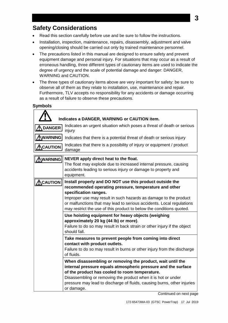
Symbols
Indicates a DANGER, WARNING or CAUTION item.
DANGER
Indicates an urgent situation which poses a threat of death or serious injury
WARNING Indicates that there is a potential threat of death or serious injury
CAUTION
Indicates that there is a possibility of injury or equipment / product damage
WARNING NEVER apply direct heat to the float.
The float may explode due to increased internal pressure, causing
accidents leading to serious injury or damage to property and
equipment.
CAUTION Install properly and DO NOT use this product outside the
recommended operating pressure, temperature and other
specification ranges.
Improper use may result in such hazards as damage to the product
or malfunctions that may lead to serious accidents. Local regulations
may restrict the use of this product to below the conditions quoted.
Use hoisting equipment for heavy objects (weighing
approximately 20 kg (44 lb) or more).
Failure to do so may result in back strain or other injury if the object
should fall.
Take measures to prevent people from coming into direct
contact with product outlets.
Failure to do so may result in burns or other injury from the discharge
of fluids.
When disassembling or removing the product, wait until the
internal pressure equals atmospheric pressure and the surface
of the product has cooled to room temperature.
Disassembling or removing the product when it is hot or under
pressure may lead to discharge of fluids, causing burns, other injuries
or damage.
Continued on next page
172-65473MA-03 (GT5C PowerTrap) 17 Jul 2019
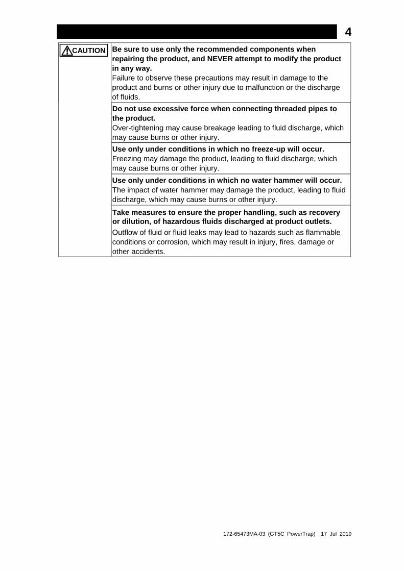
4 CAUTION
Be sure to use only the recommended components when
repairing the product, and NEVER attempt to modify the product
in any way.
Failure to observe these precautions may result in damage to the
product and burns or other injury due to malfunction or the discharge
of fluids.
Do not use excessive force when connecting threaded pipes to
the product.
Over-tightening may cause breakage leading to fluid discharge, which
may cause burns or other injury.
Use only under conditions in which no freeze-up will occur.
Freezing may damage the product, leading to fluid discharge, which
may cause burns or other injury.
Use only under conditions in which no water hammer will occur.
The impact of water hammer may damage the product, leading to fluid
discharge, which may cause burns or other injury.
Take measures to ensure the proper handling, such as recovery
or dilution, of hazardous fluids discharged at product outlets.
Outflow of fluid or fluid leaks may lead to hazards such as flammable
conditions or corrosion, which may result in injury, fires, damage or
other accidents.
172-65473MA-03 (GT5C PowerTrap) 17 Jul 2019
5
General Description
Install properly and DO NOT use this product outside the recommended operating pressure, temperature and other specification ranges. Improper use may result in such hazards as damage to the product or malfunctions which may lead to serious accidents. Local regulations may restrict the use of this product to below the conditions quoted.
CAUTION
Application
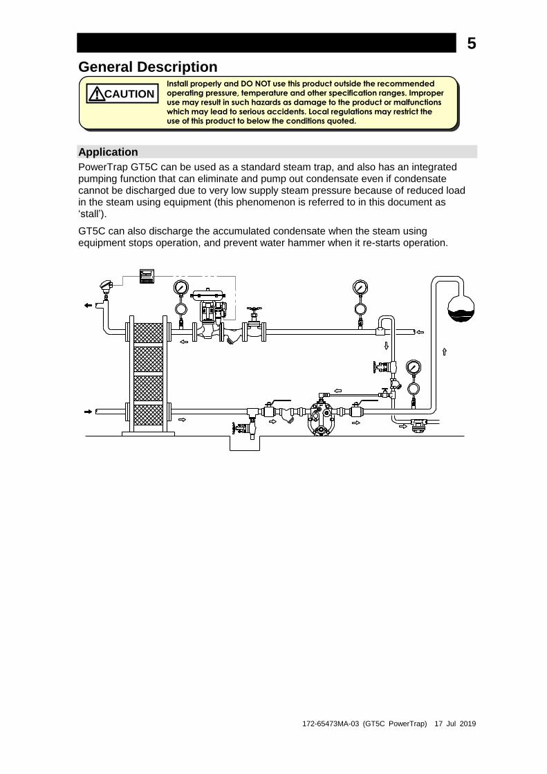
PowerTrap GT5C can be used as a standard steam trap, and also has an integrated pumping function that can eliminate and pump out condensate even if condensate cannot be discharged due to very low supply steam pressure because of reduced load in the steam using equipment (this phenomenon is referred to in this document as ‘stall’).
GT5C can also discharge the accumulated condensate when the steam using equipment stops operation, and prevent water hammer when it re-starts operation.

172-65473MA-03 (GT5C PowerTrap) 17 Jul 2019
6
Operation
Take measures to prevent people from coming into direct contact with
product outlets. Failure to do so may result in burns or other injury from
the discharge of fluids. CAUTION
(1) When condensate flows from the condensate inlet pipe through the inlet check valve
into the body of the unit, the float rises and the main valve of the trap unit is open as
shown in (A) below.
The main valve on the trap unit opens as the float rises. When Pi > Pb (when the
equipment pressure (Pi) is greater than the back pressure (Pb)), the condensate
passes through the outlet check valve and is discharged through the condensate
outlet pipe (normal trapping function).
In this case, the integrated air vent unit exhausts internal air to the outlet.
When Pi ≤ Pb, the condensate is not discharged and collects in the body of the
unit.
(2) When the float rises to its high level, the push rod on the snap-action unit rises
quickly, simultaneously closing the exhaust valve and opening the intake (motive
medium) valve. The pressure supplied by the motive medium causes the internal
pressure in the unit to become greater than the back pressure. The inlet check valve
closes and the outlet check valve is pushed open, thus discharging the condensate in
the unit through the outlet pipe, as shown in (B) below.
(3) As a result of the condensate in the unit being discharged, the water level in the unit
drops and the float descends. When the float reaches its low level, the push rod on
the snap-action unit moves down quickly, simultaneously opening the exhaust valve
and closing the intake (motive medium) valve and the status reverts to that shown in
(A) below.
Outlet Check Valve
Intake Valve [Open]
Exhaust Valve [Close]
Condensate Outlet Pipe
Body
Exhaust Valve [Open]
Intake Valve [Close]
Operation Shaft
Cover
Trap unit Float
Snap Action unit
Inlet Check Valve
Condensate Inlet Pipe
(A) Condensate Inflow (B) Condensate Discharge (Exhaust) (Motive Medium Intake)
Air Vent Unit
172-65473MA-03 (GT5C PowerTrap) 17 Jul 2019
7
Specifications
Install properly and DO NOT use this product outside the recommended
operating pressure, temperature and other specification ranges.
Improper use may result in such hazards as damage to the product or
malfunctions which may lead to serious accidents. Local regulations
may restrict the use of this product to below the conditions quoted.
CAUTION
Use only under conditions in which no freeze-up will occur. Freezing
may damage the product, leading to fluid discharge, which may cause
burns or other injury. CAUTION
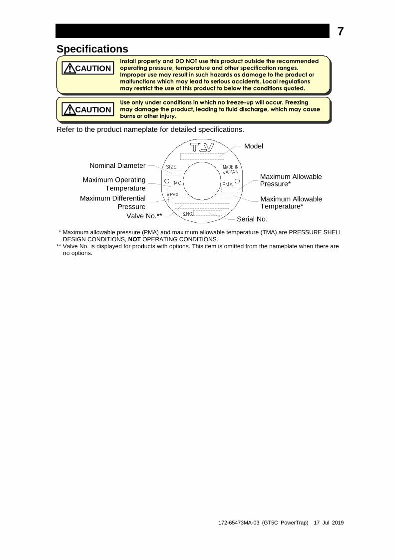
Refer to the product nameplate for detailed specifications.
Valve No.**
Nominal Diameter
Model
Maximum Allowable Pressure*
Maximum Allowable Temperature*
Serial No.
Maximum Operating
Temperature
Maximum Differential
Pressure
* Maximum allowable pressure (PMA) and maximum allowable temperature (TMA) are PRESSURE SHELL
DESIGN CONDITIONS, NOT OPERATING CONDITIONS. ** Valve No. is displayed for products with options. This item is omitted from the nameplate when there are
no options.

172-65473MA-03 (GT5C PowerTrap) 17 Jul 2019
8
Configuration
Exhaust Outlet Plug
Motive Medium Inlet
Condensate Inlet
Condensate Outlet
N0. Parts Maintenance
Kit
Repair Kit *¹
Float
Snap
Action
Spring A B C D E
1 Body
2 Cover
3 Gaskets, etc. Gasket ✔
Seal set ✔
4 Cover Bolt
5 Nameplate
6 Float ✔
7 Snap-Action Unit ✔*²
8 Snap Action Spring ✔
9 Intake-Exhaust Valve Unit ✔
10 Trap Unit ✔
11 Air Vent Unit ✔
12 Inlet Check Valve ✔
13 (Flange)
14 Plug (for drainage)
Please refer to the replacement parts list for maintenance and repair kits.
*¹ The maintenance kit should be purchased along with a repair kit, as gaskets might be required.
*² A snap action spring is also contained in the snap-action unit.
172-65473MA-03 (GT5C PowerTrap) 17 Jul 2019
9
Installation
Install properly and DO NOT use this product outside the recommended
operating pressure, temperature and other specification ranges.
Improper use may result in such hazards as damage to the product or
malfunctions which may lead to serious accidents. Local regulations
may restrict the use of this product to below the conditions quoted.
CAUTION
Use hoisting equipment for heavy objects (weighing approximately 20 kg (44 lb) or more). Failure to do so may result in back strain or other injury if the object should fall.
CAUTION
Take measures to prevent people from coming into direct contact with
product outlets. Failure to do so may result in burns or other injury from
the discharge of fluids. CAUTION
Do not use excessive force when connecting threaded pipes to the
product. Over-tightening may cause breakage leading to fluid
discharge, which may cause burns or other injury. CAUTION
Use only under conditions in which no water hammer will occur. The
impact of water hammer may damage the product, leading to fluid
discharge, which may cause burns or other injury. CAUTION
Steam System Example
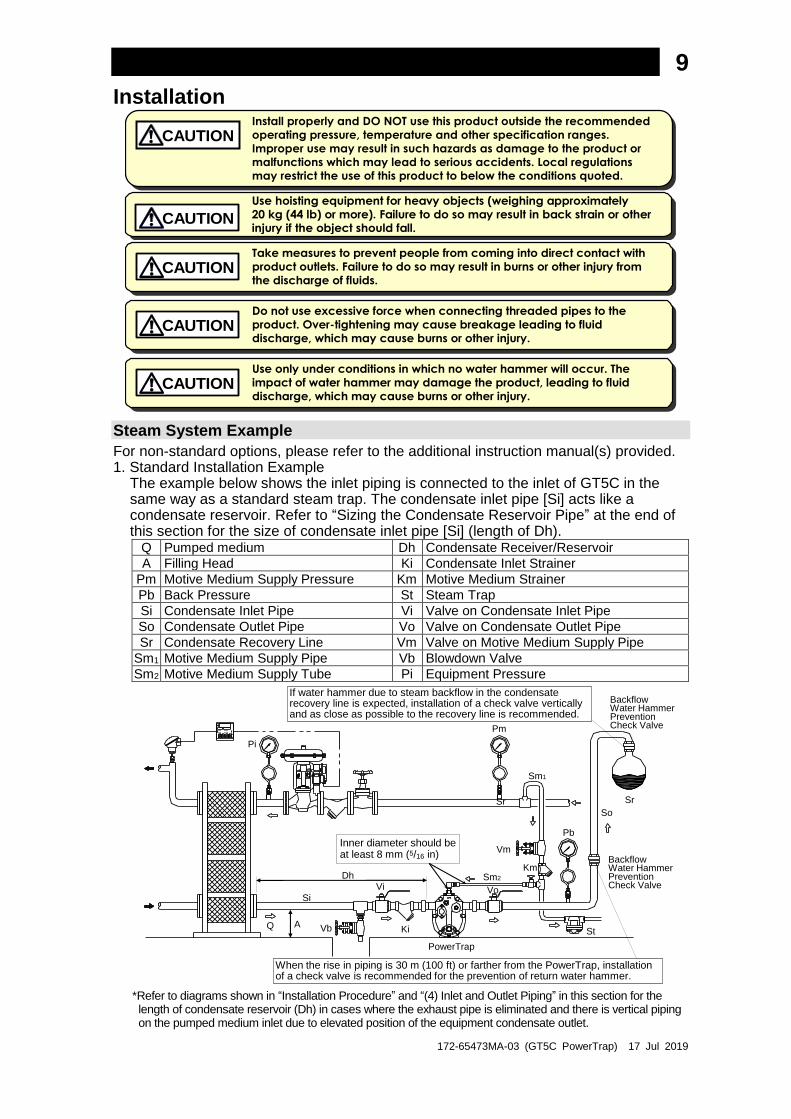
For non-standard options, please refer to the additional instruction manual(s) provided. 1. Standard Installation Example
The example below shows the inlet piping is connected to the inlet of GT5C in the same way as a standard steam trap. The condensate inlet pipe [Si] acts like a condensate reservoir. Refer to “Sizing the Condensate Reservoir Pipe” at the end of this section for the size of condensate inlet pipe [Si] (length of Dh).
Q Pumped medium Dh Condensate Receiver/Reservoir
A Filling Head Ki Condensate Inlet Strainer
Pm Motive Medium Supply Pressure Km Motive Medium Strainer
Pb Back Pressure St Steam Trap
Si Condensate Inlet Pipe Vi Valve on Condensate Inlet Pipe
So Condensate Outlet Pipe Vo Valve on Condensate Outlet Pipe
Sr Condensate Recovery Line Vm Valve on Motive Medium Supply Pipe
Sm1 Motive Medium Supply Pipe Vb Blowdown Valve
Sm2 Motive Medium Supply Tube Pi Equipment Pressure
PowerTrap
Pm
Sr
So
Pb
Sm1
Vm
Km
Vo
St
Sr
Si
Q Vb
Vi
KiA
Dh
Pi
Sm2
BackflowWater HammerPreventionCheck Valve
If water hammer due to steam backflow in the condensate recovery line is expected, installation of a check valve vertically and as close as possible to the recovery line is recommended.
When the rise in piping is 30 m (100 ft) or farther from the PowerTrap, installation of a check valve is recommended for the prevention of return water hammer.
Inner diameter should beat least 8 mm (5/16 in)
BackflowWater HammerPreventionCheck Valve
*Refer to diagrams shown in “Installation Procedure” and “(4) Inlet and Outlet Piping” in this section for the length of condensate reservoir (Dh) in cases where the exhaust pipe is eliminated and there is vertical piping on the pumped medium inlet due to elevated position of the equipment condensate outlet.
172-65473MA-03 (GT5C PowerTrap) 17 Jul 2019
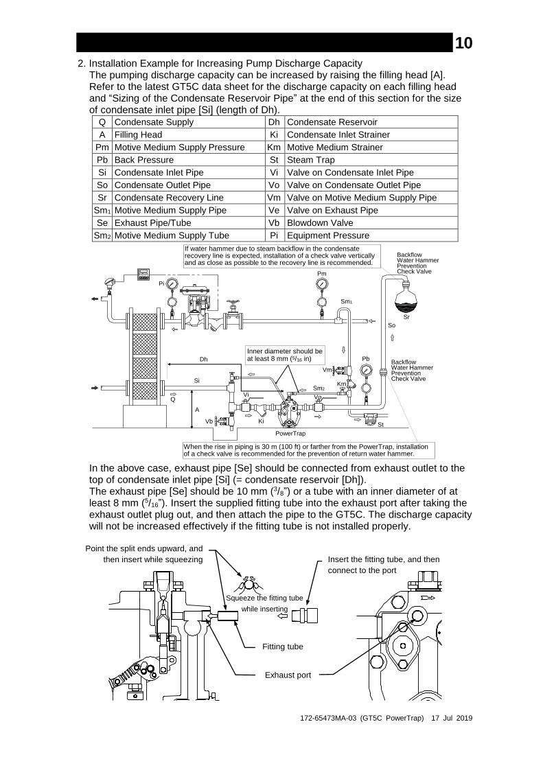
10 2. Installation Example for Increasing Pump Discharge Capacity
The pumping discharge capacity can be increased by raising the filling head [A]. Refer to the latest GT5C data sheet for the discharge capacity on each filling head and “Sizing of the Condensate Reservoir Pipe” at the end of this section for the size of condensate inlet pipe [Si] (length of Dh).
Q Condensate Supply Dh Condensate Reservoir
A Filling Head Ki Condensate Inlet Strainer
Pm Motive Medium Supply Pressure Km Motive Medium Strainer
Pb Back Pressure St Steam Trap
Si Condensate Inlet Pipe Vi Valve on Condensate Inlet Pipe
So Condensate Outlet Pipe Vo Valve on Condensate Outlet Pipe
Sr Condensate Recovery Line Vm Valve on Motive Medium Supply Pipe
Sm1 Motive Medium Supply Pipe Ve Valve on Exhaust Pipe
Se Exhaust Pipe/Tube Vb Blowdown Valve
Sm2 Motive Medium Supply Tube Pi Equipment Pressure
A
Pm
Pi
PowerTrap
So
Pb
Sm1
Vm
Km
Vo
St
Sr
Si
Q
Vb
Vi
Ki
Dh
Sm2
BackflowWater HammerPreventionCheck Valve
If water hammer due to steam backflow in the condensate recovery line is expected, installation of a check valve vertically and as close as possible to the recovery line is recommended.
When the rise in piping is 30 m (100 ft) or farther from the PowerTrap, installation of a check valve is recommended for the prevention of return water hammer.
BackflowWater HammerPreventionCheck Valve
Inner diameter should beat least 8 mm (5/16 in)
In the above case, exhaust pipe [Se] should be connected from exhaust outlet to the top of condensate inlet pipe [Si] (= condensate reservoir [Dh]). The exhaust pipe [Se] should be 10 mm (3/8”) or a tube with an inner diameter of at least 8 mm (5/16”). Insert the supplied fitting tube into the exhaust port after taking the exhaust outlet plug out, and then attach the pipe to the GT5C. The discharge capacity will not be increased effectively if the fitting tube is not installed properly.
Point the split ends upward, and
then insert while squeezing
Squeeze the fitting tube
while inserting
Insert the fitting tube, and then
connect to the port
Exhaust port
Fitting tube
172-65473MA-03 (GT5C PowerTrap) 17 Jul 2019
11
Installation Procedure
Installation, inspection, maintenance, repairs, disassembly, adjustment and valve
opening/closing should be carried out only by trained maintenance personnel.
(1) Pumped Medium:
Fluids that can be discharged through the PowerTrap are limited to steam
condensate. PowerTraps that have been specially constructed for other specific
fluids are not limited by this restriction.
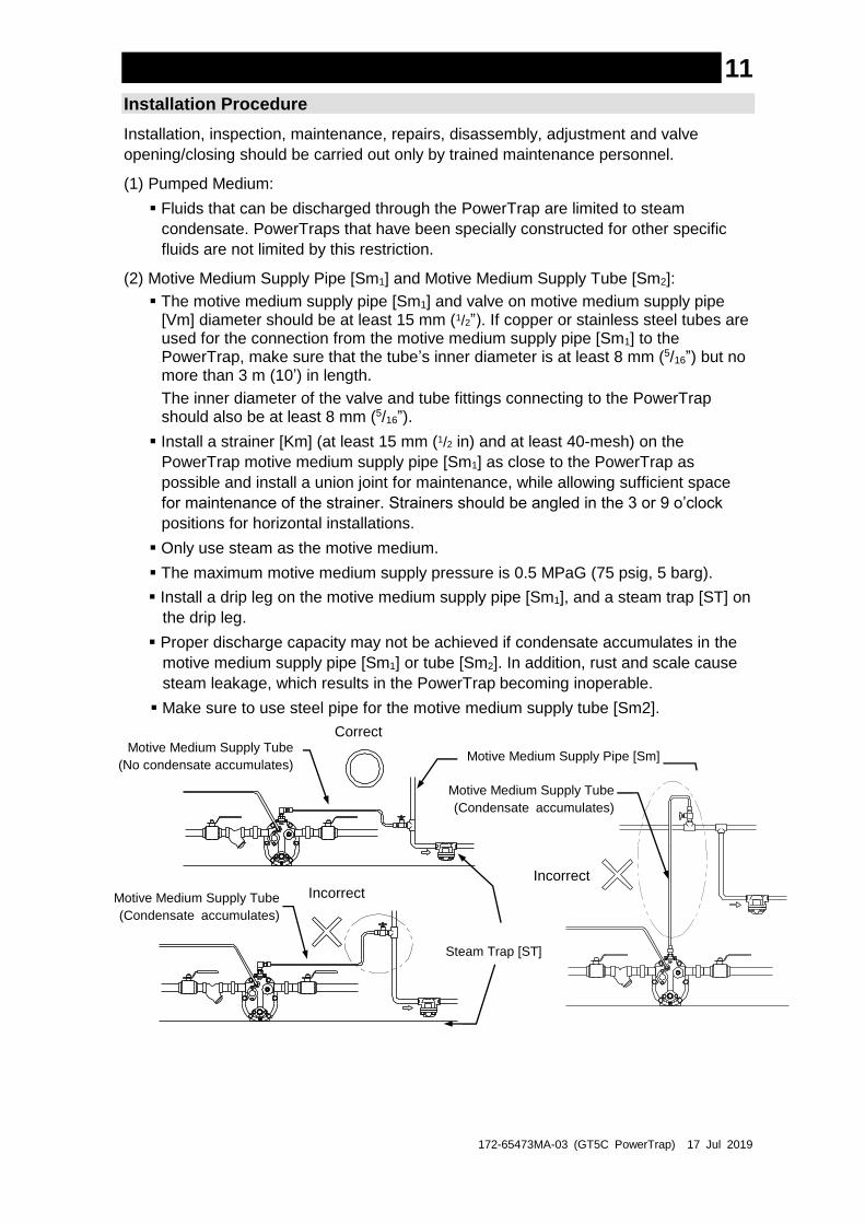
(2) Motive Medium Supply Pipe [Sm1] and Motive Medium Supply Tube [Sm2]:
The motive medium supply pipe [Sm1] and valve on motive medium supply pipe [Vm] diameter should be at least 15 mm (1/2”). If copper or stainless steel tubes are used for the connection from the motive medium supply pipe [Sm1] to the PowerTrap, make sure that the tube’s inner diameter is at least 8 mm (5/16”) but no more than 3 m (10’) in length.
The inner diameter of the valve and tube fittings connecting to the PowerTrap should also be at least 8 mm (5/16”).
Install a strainer [Km] (at least 15 mm (1/2 in) and at least 40-mesh) on the
PowerTrap motive medium supply pipe [Sm1] as close to the PowerTrap as
possible and install a union joint for maintenance, while allowing sufficient space
for maintenance of the strainer. Strainers should be angled in the 3 or 9 o’clock
positions for horizontal installations.
Only use steam as the motive medium.
The maximum motive medium supply pressure is 0.5 MPaG (75 psig, 5 barg).
Install a drip leg on the motive medium supply pipe [Sm1], and a steam trap [ST] on
the drip leg.
Proper discharge capacity may not be achieved if condensate accumulates in the
motive medium supply pipe [Sm1] or tube [Sm2]. In addition, rust and scale cause
steam leakage, which results in the PowerTrap becoming inoperable.
Make sure to use steel pipe for the motive medium supply tube [Sm2].
Motive Medium Supply Tube
(No condensate accumulates) Motive Medium Supply Pipe [Sm]
Correct
Steam Trap [ST]
Incorrect
Motive Medium Supply Tube
(Condensate accumulates)
Incorrect
Motive Medium Supply Tube
(Condensate accumulates)
172-65473MA-03 (GT5C PowerTrap) 17 Jul 2019
12
(3) Pressure Reducing Valve on the Motive Medium Supply Piping:
When the motive medium pressure [Pm] is greater than 0.5 MPaG (75 psig, 5
barg), install a TLV pressure reducing valve (such as the DR20) in order to reduce
the motive medium pressure to the PowerTrap. In order to prevent the pressure
from rising at dead end shut off, be sure to install a relief valve between the
pressure reducing valve and the PowerTrap.
The pressure setting on the pressure reducing valve should be between 0.05 and
0.15 MPa (7 and 20 psi, 0.5 and 1.5 bar) higher than the back pressure [Pb].
When the pumping capacity of the PowerTrap is insufficient for the set motive
pressure, increase this set pressure even further.
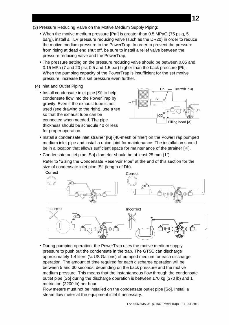
(4) Inlet and Outlet Piping
Install condensate inlet pipe [Si] to help
condensate flow into the PowerTrap by
gravity. Even if the exhaust tube is not
used (see drawing to the right), use a tee
so that the exhaust tube can be
connected when needed. The pipe
thickness should be schedule 40 or less
for proper operation.
Install a condensate inlet strainer [Ki] (40-mesh or finer) on the PowerTrap pumped
medium inlet pipe and install a union joint for maintenance. The installation should
be in a location that allows sufficient space for maintenance of the strainer [Ki].
Condensate outlet pipe [So] diameter should be at least 25 mm (1”).
Refer to “Sizing the Condensate Reservoir Pipe” at the end of this section for the
size of condensate inlet pipe [Si] (length of Dh).
During pumping operation, the PowerTrap uses the motive medium supply
pressure to push out the condensate in the trap. The GT5C can discharge
approximately 1.4 liters (3/8 US Gallons) of pumped medium for each discharge
operation. The amount of time required for each discharge operation will be
between 5 and 30 seconds, depending on the back pressure and the motive
medium pressure. This means that the instantaneous flow through the condensate
outlet pipe [So] during the discharge operation is between 170 kg (370 lb) and 1
metric ton (2200 lb) per hour.
Flow meters must not be installed on the condensate outlet pipe [So]. Install a
steam flow meter at the equipment inlet if necessary.
Tee with Plug
Correct Correct
Incorrect Incorrect
Dh
Si
Filling head [A]
172-65473MA-03 (GT5C PowerTrap) 17 Jul 2019
13
(5) Valves on the Various Pipes
In order to ensure the proper discharge capacity, use full bore ball valves or gate
valves on the pumped medium inlet [Vi] and outlet lines [Vo].
Be sure to install blowdown valve [Vb]. A bellows sealed valve is recommended,
due to the lack of leakage from the gland and easy flow rate adjustment.
Install union or flanged joints between the valves and the PowerTrap to allow for
easy maintenance.
Be sure to provide the necessary maintenance space for PowerTrap disassembly
and repair (see “Maintenance Space”).
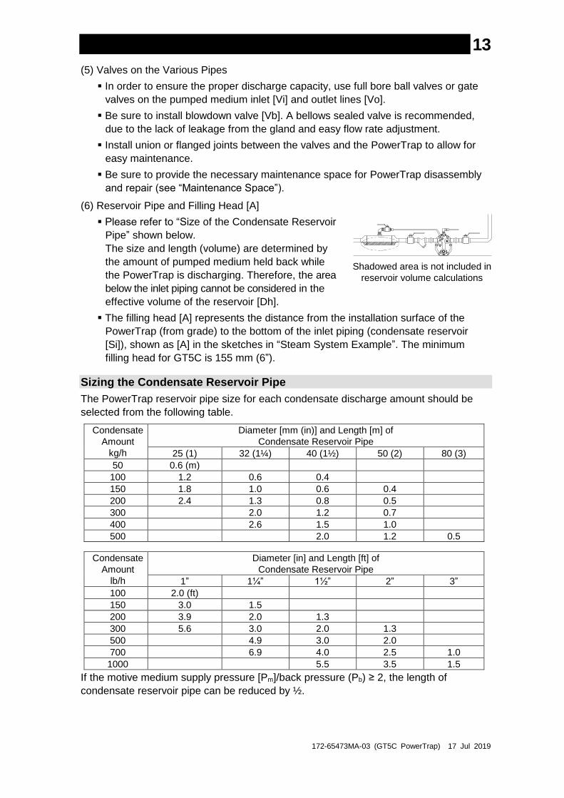
(6) Reservoir Pipe and Filling Head [A]
Please refer to “Size of the Condensate Reservoir
Pipe” shown below.
The size and length (volume) are determined by
the amount of pumped medium held back while
the PowerTrap is discharging. Therefore, the area
below the inlet piping cannot be considered in the
effective volume of the reservoir [Dh].
The filling head [A] represents the distance from the installation surface of the
PowerTrap (from grade) to the bottom of the inlet piping (condensate reservoir
[Si]), shown as [A] in the sketches in “Steam System Example”. The minimum
filling head for GT5C is 155 mm (6”).
Sizing the Condensate Reservoir Pipe
The PowerTrap reservoir pipe size for each condensate discharge amount should be
selected from the following table.
Condensate
Amount
kg/h
Diameter [mm (in)] and Length [m] of
Condensate Reservoir Pipe
25 (1) 32 (1¼) 40 (1½) 50 (2) 80 (3)
50 0.6 (m)
100 1.2 0.6 0.4
150 1.8 1.0 0.6 0.4
200 2.4 1.3 0.8 0.5
300 2.0 1.2 0.7
400 2.6 1.5 1.0
500 2.0 1.2 0.5
Condensate
Amount
lb/h
Diameter [in] and Length [ft] of
Condensate Reservoir Pipe
1” 1¼” 1½” 2” 3”
100 2.0 (ft)
150 3.0 1.5
200 3.9 2.0 1.3
300 5.6 3.0 2.0 1.3
500 4.9 3.0 2.0
700 6.9 4.0 2.5 1.0
1000 5.5 3.5 1.5
If the motive medium supply pressure [Pm]/back pressure (Pb) ≥ 2, the length of
condensate reservoir pipe can be reduced by ½.
Shadowed area is not included in
reservoir volume calculations

172-65473MA-03 (GT5C PowerTrap) 17 Jul 2019
14
Maintenance Space and Tolerance Angle for Installation
Maintenance Space
The maintenance space shown in the figure below should be provided to enable
inspection and disassembly/repair of the PowerTrap.
Tolerance Angle for Installation
The product should be inclined no more than 3°. Make sure the body is installed with the
raised TLV lettering on the body horizontal.
Unit: mm (in)
100 (4)
100 (4)
100 (4
)

172-65473MA-03 (GT5C PowerTrap) 17 Jul 2019
15
Operation and Periodic Inspection
After all piping work has been completed in accordance with the specific piping system designed when the decision to utilize the PowerTrap was made, check once again to make sure that all pipe connections have been tightened, gaskets have been inserted where needed and all parts are securely installed.
At the start-up of operation, large quantities of condensate may flow, causing the PowerTrap to momentarily overload. Open the inlet valve gradually so that the condensate flows in slowly.
WARNING
Install properly and DO NOT use this product outside the recommended
operating pressure, temperature and other specification ranges.
Improper use may result in such hazards as damage to the product or
malfunctions which may lead to serious accidents. Local regulations
may restrict the use of this product to below the conditions quoted.
CAUTION
When disassembling or removing the product, wait until the internal
pressure equals atmospheric pressure and the surface of the product
has cooled to room temperature. Disassembling or removing the
product when it is hot or under pressure may lead to discharge of fluids,
causing burns, other injuries or damage.
CAUTION
Be sure to use only the recommended components when repairing the
product, and NEVER attempt to modify the product in any way. Failure to
observe these precautions may result in damage to the product or burns
or other injury due to malfunction or the discharge of fluids.
CAUTION
Installation, inspection, maintenance, repairs, disassembly, adjustment and valve
opening/closing should be carried out only by trained maintenance personnel.
Operation
(1) Valve Operation
During the first operation after installation, or re-operation after a long shutdown,
open blowdown valve [Vb] (ensuring that the area around the opening is safe) to
eliminate rust and scale completely. Refer to the “Steam System Example” drawings
in the “Installation” section to become familiar with the symbols used for the various
valves.
If water hammer has occurred, immediately cease operation and close any valves
that are operating.
a) Slowly open the valve [Ve] on the exhaust pipe.
b) Slowly open the valve [Vm] on the motive medium supply pipe. Make sure that there
is no sound of flow from the exhaust pipe [Se] or the condensate inlet pipe [Si].
c) Slowly open the valve [Vo] on the pumped medium outlet pipe.
d) Slowly open the valve [Vi] on the pumped medium inlet pipe.
e) During normal trapping operation (equipment side pressure > back pressure), the
GT5C discharges condensate continuously. During stall or reverse pressure
(equipment side pressure ≤ back pressure), the GT5C switches to pumping
operation. The PowerTrap is normal if it operates intermittently during pumping
operation; first exhausting the motive medium to fill with pumped medium, then
taking in motive medium to force the condensate out.
The interval of operation will vary greatly depending on the amount of pumped
medium inflow, the temperature, the motive medium (steam) pressure. (The
interval of operation is considered the length of time between the start of one
discharge cycle and the start of the next discharge cycle.)
172-65473MA-03 (GT5C PowerTrap) 17 Jul 2019
16
The relation between the interval of operation Tc (seconds) and the amount of
inflowing pumped medium (Q or Qp) can be roughly determined using the
following formula:
Tc = 5,000/Q Q = 5,000/Tc Q: amount of inflowing pumped medium (kg/h)
Tc = 11,111/Qp Qp = 11,111/Tc Qp: amount of inflowing pumped medium (lb/h)
(2) If an error such as a leak or water hammer occurs after beginning PowerTrap
operation, shut off the valves immediately in the following order:
valve [Vm] on motive medium supply pipe pumped medium inlet valve [Vi]
pumped medium outlet valve [Vo] valve [Ve] on exhaust pipe
(3) Whenever any type of malfunction is suspected in the PowerTrap, refer to the
“Troubleshooting” section.
Periodic Inspection and Diagnosis
There are two types of periodic inspection: the visual inspection and the disassembly
inspection.
(1) Visual Inspection
As a general rule, this inspection should be performed at least once every 3
months.
Check the following items:
a) There should be no leakage from the PowerTrap or from any of the connections.
b) The PowerTrap unit should make continuous sound during trapping operation
(equipment side pressure > back pressure).
c) The PowerTrap unit should be operating cyclically without continuous sound in
the motive medium supply pipe or the exhaust pipe during the pumping
operation (equipment side pressure ≤ back pressure).
d) Pumped medium should not accumulate in the (steam-using) equipment, and
the temperature of the equipment should not be abnormally low.
e) There should not be any abnormal noise (such as water hammer) from the
pumped medium outlet pipe or the pumped medium recovery line when the
PowerTrap operates.
(2) Disassembly Inspection
Refer to the “Disassembly/Reassembly” section.
As a general rule, this inspection should be performed at least once every 2 years.
When inspecting the interior of the unit, check the following items:
a) Make sure the snap-action unit moves up and down smoothly as the float rises
and falls.
b) Make sure the valve of the trap unit moves up and down smoothly as it opens
and closes.
c) Make sure the intake/exhaust valves move up and down smoothly.
d) Make sure the float is not damaged and is not filled with water.
e) Make sure all nuts and bolts are properly installed and fastened.
f) Check to make sure that there is no foreign matter sticking to the shafts and
levers of any of the units, and make sure there is no abnormal wear.
When reassembling, be sure to replace the body and cover gaskets with new
gaskets if damaged.
Also, replace any parts that are broken or show serious wear.
If any parts require replacement, refer to the “Replacement Parts” List.

172-65473MA-03 (GT5C PowerTrap) 17 Jul 2019
17
Disassembly/Reassembly
NEVER apply direct heat to the float. The float may explode due to increased internal pressure, causing accidents leading to serious injury or damage to property and equipment.
WARNING
Use hoisting equipment for heavy objects (weighing approximately 20 kg (44 lb) or more). Failure to do so may result in back strain or other injury if the object should fall.
CAUTION
When disassembling or removing the product, wait until the internal
pressure equals atmospheric pressure and the surface of the product
has cooled to room temperature. Disassembling or removing the
product when it is hot or under pressure may lead to discharge of fluids,
causing burns, other injuries or damage.
CAUTION
Do not use excessive force when connecting threaded pipes to the
product. Over-tightening may cause breakage leading to fluid
discharge, which may cause burns or other injury. CAUTION
Use the procedures on the following pages to remove components. Use the same
procedures in reverse to reassemble. (Installation, inspection, maintenance, repairs,
disassembly, adjustment and valve opening/closing should be carried out only by trained
maintenance personnel.)
In cases where sufficient maintenance space has been provided for (see “Maintenance
Space”), maintenance can be carried out without disconnecting the inlet and outlet
piping. Where there is insufficient maintenance space, first disconnect the inlet and
outlet piping, and then move the unit to a spacious area in which maintenance can be
carried out safely.
When reassembling:
Also replace any gaskets, units or parts that are broken or show serious wear. If
any parts require replacement, refer to “Replacement Parts”.
When reassembling, coat threads and bolts with anti-seize. Tighten the body and
cover bolts in a uniform manner left and right, being careful to avoid uneven
tightening.
If drawings or other special documentation were supplied for the product, any
torque given there takes precedence over values shown here.
172-65473MA-03 (GT5C PowerTrap) 17 Jul 2019
18
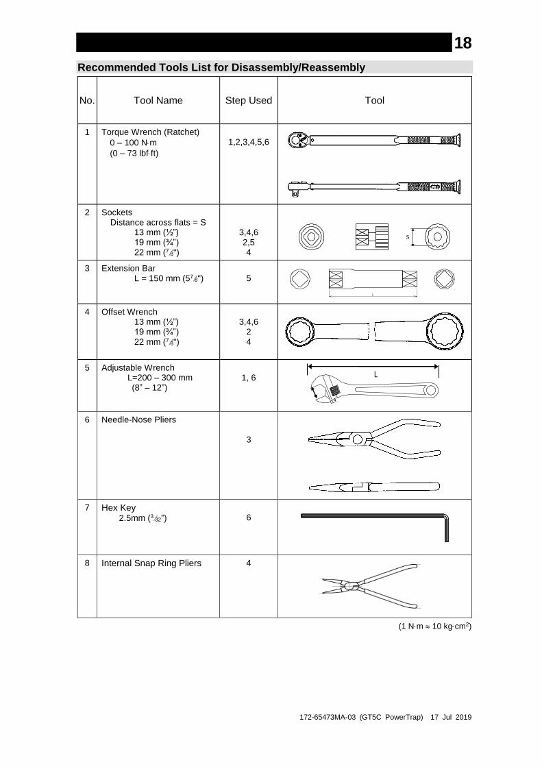
Recommended Tools List for Disassembly/Reassembly
No. Tool Name Step Used Tool
1 Torque Wrench (Ratchet)
0 – 100 Nm
(0 – 73 lbfft)
1,2,3,4,5,6
2 Sockets Distance across flats = S
13 mm (½”) 19 mm (¾”) 22 mm (78")
3,4,6 2,5 4
S
3 Extension Bar L = 150 mm (578")
5
4 Offset Wrench 13 mm (½”) 19 mm (¾”) 22 mm (78")
3,4,6
2 4
5 Adjustable Wrench L=200 – 300 mm (8” – 12”)
1, 6
6 Needle-Nose Pliers
3
7
Hex Key
2.5mm (332”)
6
8
Internal Snap Ring Pliers 4
(1 Nm 10 kgcm2)
L
S

172-65473MA-03 (GT5C PowerTrap) 17 Jul 2019
19
1. Before Removing/Reattaching
Discharge the condensate from the body before removing parts.
(1 Nm 10 kgcm2)
Part Disassembly Reassembly
Plug • Discharging condensate is carried out with the intake (motive medium), exhaust, inlet and outlet piping still connected to the unit.
• Using an adjustable wrench, slowly loosen plug to release pressure and discharge fluid. Take care to avoid being burned by fluid discharge. (Opening this plug may help to discharge condensate in the body more easily when the drain plug is opened.)
• Wrap threads with 3 – 3.5 turns of sealing tape or apply sealing compound.
• Tighten to a torque of
30 Nm (22 lbfft).
Drain Plug
• Using an adjustable wrench, slowly loosen plug to release pressure and discharge fluid, take care to avoid being burned by fluid discharge.
• Wrap threads with 3 – 3.5 turns of sealing tape or apply sealing compound.
• Tighten to a torque of
30 Nm (22 lbfft).
Plug
Drain Plug

172-65473MA-03 (GT5C PowerTrap) 17 Jul 2019
20 2. Removing/Reattaching the Body from/to the Cover
Prepare a new, replacement cover gasket before beginning this step.
Cover Bolts • Using a 19 mm (¾”) socket wrench, loosen each bolt slowly one turn in an alternating diagonal pattern.
• Once all bolts have been loosened, verify that there is no internal pressure before completely removing the bolts.
• Reverse steps in disassembly.
• Tighten to a torque of
60 Nm (44 lbfft).
Body / Cover
• When removing the body, lift the float and the float lever slightly to avoid contact with the float.
• Reverse steps in disassembly while referring to the figure below.
Cover Gasket
• The gasket may be damaged or destroyed upon disassembly, as it is inlaid in the body and may adhere to that groove; using a scratch-free scraper, carefully scrape the gasket from the body.
• Replace with a new gasket if damaged.
(1 Nm 10 kgcm2)
3. Removing/Reattaching the Snap Action Unit
Part Disassembly Reassembly
Bolts / Spring Washers
• Using a 13 mm (½”) socket wrench, slowly loosen the two bolts that are holding the snap-action unit to the cover.
• Coat the bolt threads with anti-seize. • Be sure to reinsert spring washers. • Assemble the bolts and spring
washers, then finger-tighten.
• Tighten to a torque of 35 Nm (26 lbfft)
Snap-Action Unit
• Support the snap-action unit with one hand while removing the loosened bolts and spring washers from the cover with the other.
• Remove snap action unit from the cover holding it down.
• Be careful not to let any parts fall, including the coil spring or intake-exhaust valve.
• Do not tip the snap-action unit, as the intake-exhaust valve may fall off.
• When working with the snap-action unit, take care not to pinch fingers, etc.
• Reinsert the snap-action unit very carefully, inserting tips of intake-exhaust valve into the bottom of their respective valve seats, then continuing to insert all the way up into the valve seat as you reattach the snap-action unit.
• Align the snap-action unit bolt holes to the bolt holes in the cover.
Continued on next page
Cover Gasket Cover Bolt

172-65473MA-03 (GT5C PowerTrap) 17 Jul 2019
21
Part Disassembly Reassembly
Intake-Exhaust Valve
• Remove the intake-exhaust valve by rotating it 90º.
• Remove the coil spring.
• Reattach the intake-exhaust valve by rotating it 90º.
• Reattach the coil spring.
Float/ Float Pin/ Spring Washer/ Split Pin
• Remove the float and the float holder by removing the float pin and pulling out the split pin.
• Be careful not to let the float fall. Do not drop the float or lose the washers.
• Replace the float if it is filled with water or cracked.
• Reattach the float and the spring holder by inserting the float pin and the split pin. The coil spring will be inserted later.
• If readjusting the position of the trap valve, refer to “Positioning Adjustment of Trap Valve” to adjust the position of the trap valve, before reattaching the float.
Trap Valve/ Connecting Pin/ Spring Washer/ Split Pin
• Replace trap unit if the trap valve is damaged.
• Remove the trap valve by removing the connector pin while pulling out the split pin.
• Be careful not to allow the trap valve to fall or lose the washers.
• The trap valve can be reused if not damaged.
• Reattach the trap valve by inserting the connector pin and the split pin.
Snap-Action Unit Hex. Bolt (M8)
Spring Washer
Intake-Exhaust Valve
Coil Spring
Intake-Exhaust Valve
Coil Spring Float Pin
Spring Holder
Split Pin Trap Valve
Split Pin
Connector Pin
Washer
Washer

172-65473MA-03 (GT5C PowerTrap) 17 Jul 2019
22
4. Removing/Reattaching Each Unit
Part Disassembly Reassembly
Intake-Exhaust Valve Seat/ Bolt/Snap Ring Screen/Steel Ball/O-Ring/ Gasket
• Remove bolts with a 13 mm (½”) socket wrench.
• Remove the intake-exhaust valve seat from the cover.
• Be careful not to let the steel ball and the screen fall when removing the snap ring.
• Remove the O-ring. • Clean the sealing surfaces.
• Replace with a new O-ring • Replace with a new gasket if it is
damaged. • Coat O-ring with heatproof grease
and be sure to clean the mounting surface in the cover.
• Tighten to a torque of 10 Nm
(7 lbfft).
Inlet Check Valve Seat/ Bolt/O-Ring/ Gasket
• Remove bolts with a 13 mm (½”) socket wrench.
• Remove the inlet check valve seat from the cover. If difficult, screw the bolt into the center of the inlet check valve and use it to remove the valve seat.
• Remove the O-ring. • Clean the sealing surfaces.
• Replace with a new O-ring • Replace with a new gasket if it is
damaged. • Coat O-ring with heatproof grease
and be sure to clean the mounting surface in the cover.
• In order to orient the hinge of the valve upwards, be sure the indentation is pointed upwards.
• Tighten to a torque of 10 Nm
(7 lbfft).
Outlet Check Valve/Spring Holder/Coil Spring/Gasket
• Take out the outlet check valve unit before removing the trap unit.
• Remove the spring holder with a 22 mm (78") socket wrench.
• Be careful not to let the coil spring and the gasket fall.
• Be sure to clean the mounting surface of trap valve seat.
• Replace with a new gasket if it is damaged.
• Tighten to a torque of 60 Nm (44
lbfft).
Trap Valve Seat /Bolt/ O-Ring/Gasket
• Remove bolts with a 13 mm (½”) socket wrench.
• Remove the trap valve seat from the cover.
• Replace with a new O-ring • Replace with a new gasket if it is
damaged. • Coat O-ring with heatproof grease
and be sure to clean the mounting surface in the cover.
• In order to assure proper flow direction, be sure the indentation is pointed upwards.
• Tighten to a torque of 10 Nm
(7 lbfft).
(1 Nm 10 kgcm2)
Cover
Gasket
Intake-Exhaust Valve Seat
Steel Ball
Screen
Bolt
O-Ring
Bolt
Trap Valve Seat
Gasket
Gasket
O-Ring
Inlet Check Valve
Bolt
The indentation should point upwards
Outlet Check Valve
Gasket Coil Spring Holder
The indentation should point upwards
O-Ring
Snap Ring

172-65473MA-03 (GT5C PowerTrap) 17 Jul 2019
23 5. Removing/Reattaching of Air Vent Unit
Part / Step Disassembly Reassembly
Spring Clip/ X-element/ Air Vent Valve Seat/ X-element Guide
• Remove the spring clip with your fingers.
• Remove the X-element. • Remove the air vent valve
seat with a 19 mm (¾”)
socket wrench. • Remove the X-element
Guide
• Make sure that the check valve (a small steel ball) in the air vent valve seat can open and close smoothly with the spring.
• Tighten to a torque of 35 Nm (26 lbfft).
(1 Nm 10 kgcm2)
X-element
Air Vent Unit
Spring Clip
Air Vent Valve Seat (and steel ball)
X-element Guide
Cover
Cover

172-65473MA-03 (GT5C PowerTrap) 17 Jul 2019
24
6. Positioning Adjustment of the Trap Valve
Adjustment of the trap valve position is required if leakage occurs from the trap valve or a gap between the orifice and the trap valve exists.
Item Procedure
Installation of Snap Action Unit
• Install the snap action unit assembled with the motive intake valve and the trap valve (the float is not yet attached) to the cover assembled with the trap valve seat and the intake-exhaust valve seat.
• Using a 13 mm (½”) socket wrench, tighten two bolts equally to a torque of 35
Nm (26 lbfft).
Adjustment of the Trap Valve Position
• Using a 2.5mm (3/32”) allen wrench, loosen both stopper screws which fix the bolt (M10) located above the trap valve.
• To determine proper float orientation, adjust bolt (M10) so that there is a gap between the snap-action lever and the bolt (M10) when the float is in the lowered position. Push the trap valve against the trap valve seat and hold it with one finger while adjusting the bolt (M10) so that there is no gap between the snap-action lever and the bolt.
• Using a 2.5mm (3/32”) allen wrench, tighten both screws to a torque of 3 Nm
(2 lbfft) to fix the bolt (M10).
(1 Nm 10 kgcm2)
Installation of Snap Action Unit
Adjustment of the Trap Valve Position
Trap Valve Seat
Intake-Exhaust Valve
Trap Valve
Intake-Exhaust Valve Seat
Spring Washer
Bolt (M8) Snap-Action Unit
Cover
2. Make clearance 4. No clearance
1. Loosen 5. Tighten
3. Hold the Trap Valve
Bolt (M10)
172-65473MA-03 (GT5C PowerTrap) 17 Jul 2019
25
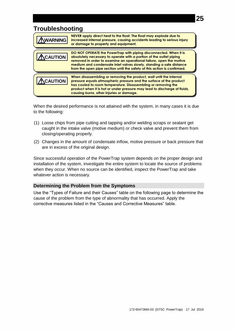
Troubleshooting
NEVER apply direct heat to the float. The float may explode due to
increased internal pressure, causing accidents leading to serious injury
or damage to property and equipment. WARNING
DO NOT OPERATE the PowerTrap with piping disconnected. When it is absolutely necessary to operate with a portion of the outlet piping removed in order to examine an operational failure, open the motive medium and condensate inlet valves slowly, standing a safe distance from the open pipe section until the safety of this action is confirmed.
CAUTION
When disassembling or removing the product, wait until the internal
pressure equals atmospheric pressure and the surface of the product
has cooled to room temperature. Disassembling or removing the
product when it is hot or under pressure may lead to discharge of fluids,
causing burns, other injuries or damage.
CAUTION
When the desired performance is not attained with the system, in many cases it is due
to the following:
(1) Loose chips from pipe cutting and tapping and/or welding scraps or sealant get
caught in the intake valve (motive medium) or check valve and prevent them from
closing/operating properly.
(2) Changes in the amount of condensate inflow, motive pressure or back pressure that
are in excess of the original design.
Since successful operation of the PowerTrap system depends on the proper design and
installation of the system, investigate the entire system to locate the source of problems
when they occur. When no source can be identified, inspect the PowerTrap and take
whatever action is necessary.
Determining the Problem from the Symptoms
Use the “Types of Failure and their Causes” table on the following page to determine the
cause of the problem from the type of abnormality that has occurred. Apply the
corrective measures listed in the “Causes and Corrective Measures” table.

172-65473MA-03 (GT5C PowerTrap) 17 Jul 2019
26
Types of Failure and their Causes
Detailed explanations of the meanings of the numbers listed in the “Types of Failure” column are found in the “Causes and Corrective Measures” table.
Pump is in the correct operating condition when Pi ≤ Pb (equipment pressure Pi is equal to or lower than back pressure Pb ). Trap is in the correct operating condition when Pi >
Pb, (equipment pressure Pi is higher than back pressure Pb ).
Type
s o
f F
ailu
re (
Ca
teg
ory
A –
G)
and
Co
rre
ctive M
easu
res (
Ca
use
s 1
– 5
)
G
1,2
1,2
F
3 1
1 1
1
E 1
5 2 3
1
3,4
,5
2
4
5
1,2
D
1 1
1,2
,3
C
1,2
1,2
3
B 2 1
A
1,2
,3
1,4
Is t
here
a
co
ntin
uo
us f
low
ing
so
un
d f
rom
th
e
exha
ust
pip
e?
NO
YE
S
NO
NO
YE
S
NO
NO
YE
S
NO
NO
YE
S
Ha
s p
um
ped
me
diu
m a
ccum
ula
ted
in
th
e e
qu
ipm
en
t, o
r h
as w
ate
r
ham
me
r o
ccurr
ed
?
Ha
s s
team
le
ake
d in
th
e o
utle
t sid
e o
r h
as w
ate
r h
am
me
r o
ccurr
ed in
outle
t p
ipin
g?
Ha
s r
evers
e f
low
se
nt
ste
am
back in
to t
he e
qu
ipm
en
t?
Is t
here
a c
ontin
uo
us
flo
win
g s
oun
d f
rom
the m
otive m
ediu
m
su
pp
ly p
ipe?
NO
YE
S
NO
YE
S
YE
S
NO
YE
S
YE
S
NO
YE
S
YE
S
Ha
s p
um
ped
me
diu
m
co
llecte
d in
th
e
Po
we
rTra
p?
NO
YE
S
NO
YE
S
Ha
s t
he
Po
we
rTra
p
ope
rate
d a
t
least
once
?
NO
YE
S
Does not Pump Does not Trap

172-65473MA-03 (GT5C PowerTrap) 17 Jul 2019
27
Causes and Corrective Measures
Category Cause Procedure
A. A valve on the pipeline is closed
1. The valve on the motive medium supply pipe is closed
2. The valve on the exhaust pipe is closed
3. The valve on the condensate inlet pipe is closed
4. The valve on the condensate outlet pipe is closed
• Slowly open the valve, using the proper procedure
Check valves around the PowerTrap. If they are open, check other valves on pipes connected to the PowerTrap, as the valve may have been left closed due to other repairs or maintenance
B. The strainer is clogged
1. The strainer on the motive medium supply pipe is clogged
2. The strainer on the condensate inlet pipe is clogged
• Clean the strainer
Please note that a large amount of rust and/or scale may accumulate during initial startup of seasonal-use equipment.
C. Faulty motive medium pressure, back pressure or pressure inside equipment
1. The motive medium supply pressure is less than the back pressure
• When the motive medium pressure is decreasing, adjust the pressure reducing valve on the supply pipe or connect to a separate high-pressure line
• If the back pressure has increased, check to see if a steam trap connected to the pumped medium recovery line is blowing (see “Steam System Example”) and check for any valves that have been left closed on the pumped medium recovery line
• The motive medium pressure must be about 0.1 MPa (15 psi, 1 bar) higher than the back pressure.
2. Insufficient motive medium
• If the motive medium supply pipe is too small, change to a larger size pipe; the pipe should be at least 15 mm (½”) near the PowerTrap
• In case a tube is used for connecting the motive medium pipe to the PowerTrap, the tube’s inner diameter (including valves and fittings in between) should be at least 8mm (5/16”) and within 2m (6½’) length.
3. Pressure inside equipment or motive medium supply pressure exceeds maximum operating pressure of PowerTrap
• When the pressure inside the equipment or the motive medium supply pressure exceeds the maximum operating pressure of the PowerTrap, the intake-exhaust valve or the trap valve stays closed, which results in inability to discharge condensate. Reduce the pressure to lower than the maximum operating pressure
• Check the reason that the pressure inside equipment or motive medium supply pressure has increased, and take any necessary measures to fix it

172-65473MA-03 (GT5C PowerTrap) 17 Jul 2019
28
Category Cause Procedure
D. Faulty piping
1. The exhaust is abnormal
2. The pumped medium inlet pipe is too small
3. Not enough pumped medium is flowing through the pumped medium inlet valve
• Air-locking or vapor-locking has occurred. The exhaust pipe is connected to the reservoir (inlet pipe), but the pumped medium may not be exchanged for the medium inside the PowerTrap for the following reasons:
1. There are places that accumulate condensate such as a U-shaped pipe between the exhaust port and the reservoir (inlet pipe)
2. The inner diameter of the exhaust pipe or tube is less than 8 mm (5/16”)
3. The fitting tube is not installed properly. Change and correct the pipe Refer to “Installation Procedure”
• Normal pumped medium flow may not be obtained if the pumped medium inlet pipe is too small or the valve on the pumped medium inlet pipe is a needle valve or one with a small Cv value.
• The pipe and stop valve size must be increased to the design pipe size, and a full bore ball valve or gate valve must be used
E. Faulty PowerTrap
1. Dirt or scale is caught in the motive medium intake-exhaust valve or the valve is worn
2. Dirt or scale is caught in the intake-exhaust valve seat or the valve seat is worn
3. The snap-action unit is obstructed by dirt or scale or its operation is otherwise faulty
4. The float is broken or filled with water
5. Dirt or scale is caught in the trap unit, resulting in faulty valve opening/closing
• If the PowerTrap does not operate for long periods of time, in spite of the fact that pumped medium has collected in the reservoir or equipment, if there is no sound at all of the operating medium flowing in the motive medium supply pipe/tube and the exhaust pipe/tube, it is possible that the PowerTrap is faulty. Note, however, that this phenomenon will also occur when the motive medium pressure is equal to or less than the back pressure
• If the PowerTrap does not operate for long periods of time and the sound of the operating medium can be heard continuously in the motive medium supply pipe/tube, the PowerTrap is faulty
Disassemble the PowerTrap, and inspect the following items:
1. Raise and lower the float and check to make sure the snap-action unit operates properly
2. Check the motive medium intake-exhaust valve and valve seat to make sure there is no dirt or scale caught or any other abnormality
3. Check other possible factors that might hinder operation
After performing the above inspection, repair any defects discovered or replace the PowerTrap

172-65473MA-03 (GT5C PowerTrap) 17 Jul 2019
29
Category Cause Corrective Measure
F. Faulty check valve
1. Dirt or scale is caught in the pumped medium inlet check valve or the valve is worn or getting hung up
• The operating medium that has been supplied is leaking from the inlet check valve, preventing the pressure inside the trap from increasing; as a result, the pumped medium is not discharged
Disassembly and inspection is required
2. Dirt or scale is caught in the pumped medium outlet check valve or the valve is worn or getting hung up
• The discharged pumped medium has flowed back into the PowerTrap, causing the interval at which the unit operates to grow shorter and reducing its discharge capacity
Disassembly and inspection is required
G. Degradation or damage of gasket and O-ring
1. Damage when assembling
2. Aging degradation
• When condensate or steam leaks from the PowerTrap, tighten the bolts with the proper torque or replace the gasket with a new one.
• When steam leaks into the equipment (to the pumped medium inlet side) or outlet piping, check the O-ring.
172-65473MA-03 (GT5C PowerTrap) 17 Jul 2019
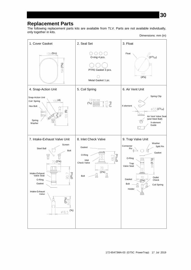
30
1. Cover Gasket 2. Seal Set 3. Float
4. Snap-Action Unit 5. Coil Spring 6. Air Vent Unit
7. Intake-Exhaust Valve Unit 8. Inlet Check Valve 9. Trap Valve Unit
(3/4)
(7/ 1
6)
Replacement Parts The following replacement parts kits are available from TLV. Parts are not available individually, only together in kits.
Dimensions: mm (in)
(5½)
(7⅝
)
Float
(4⅝)
(315/16)
(4)
Spring
Washer
(5)
Snap-Action Unit
Coil Spring
Hex Bolt X-element
Spring Clip
Air Vent Valve Seat (and Steel Ball)
X-element Guide
(15/16)
(2¾)
Screen
Bolt
Intake-Exhaust Valve Seat
Steel Ball
O-Ring
Gasket
(39/ 1
6)
Intake-Exhaust Valve
(¾)
(23/ 8
)
Gasket
Bolt
O-Ring
Inlet Check Valve
(2¾)
(21
1/ 1
6)
Trap Valve Seat
Coil Spring
Holder
Bolt
Gasket
Gasket Outlet Check Valve
Washer
Split Pin Connector Pin
(2¾)
(3 ⅞
) O-Ring
O-ring 4 pcs.
PTFE Gasket 3 pcs.
Metal Gasket 1 pc.
172-65473MA-03 (GT5C PowerTrap) 17 Jul 2019
31
Product Warranty
1. Warranty Period
One year following product delivery.
2. Warranty Coverage
TLV CO., LTD. warrants this product to the original purchaser to be free from
defective materials and workmanship. Under this warranty, the product will be
repaired or replaced at our option, without charge for parts or labor.
3. This product warranty will not apply to cosmetic defects, nor to any product
whose exterior has been damaged or defaced; nor does it apply in the
following cases:
1) Malfunctions due to improper installation, use, handling, etc., by other
than TLV CO., LTD. authorized service representatives.
2) Malfunctions due to dirt, scale, rust, etc.
3) Malfunctions due to improper disassembly and reassembly, or
inadequate inspection and maintenance by other than TLV CO., LTD.
authorized service representatives.
4) Malfunctions due to disasters or forces of nature.
5) Accidents or malfunctions due to any other cause (such as water
hammer) beyond the control of TLV CO., LTD.
4. Under no circumstances will TLV CO., LTD. be liable for consequential
economic loss damage or consequential damage to property.

172-65473MA-03 (GT5C PowerTrap) 17 Jul 2019
32
Service For Service or Technical Assistance: Contact your TLV representative or your TLV office.
In East Asia:
36 Kaki Bukit Place, #02-01/02, Singapore 416214 Tel: [65]-6747 4600 Fax: [65]-6742 0345
Room 5406, No. 103 Cao Bao Road, Shanghai, China 200233 Tel: [86]-21-6482-8622 Fax: [86]-21-6482-8623
No.16, Jalan MJ14, Taman Industri Meranti Jaya, 47120 Puchong, Selangor, Malaysia Tel: [60]-3-8052-2928 Fax: [60]-3-8051-0899
252/94 (K-L) 17th Floor, Muang Thai-Phatra Complex Tower B, Rachadaphisek Road, Huaykwang, Bangkok 10310, Thailand Tel: [66]-2693-3799 Fax: [66]-2693-3979
#302-1 Bundang Technopark B, 723 Pangyo-ro, Budang, Seongnam, Gyeonggi, 13511 Korea Tel: [82]-(0)31-726-2105 Fax: [82]-(0)31-726-2195
In North America:
13901 South Lakes Drive, Charlotte, NC 28273-6790, U.S.A. Tel: [1]-704-597-9070 Fax: [1]-704-583-1610
In Mexico and Latin America:
Av. Jesús del Monte 39-B-1001, Col. Hda. de las Palmas, Huixquilucan, Edo. de México, 52763, Mexico Tel: [52]-55-5359-7949 Fax: [52]-55-5359-7585
In Europe:
Daimler-Benz-Straße 16-18, 74915 Waibstadt, Germany Tel: [49]-(0)7263-9150-0 Fax: [49]-(0)7263-9150-50
Star Lodge, Montpellier Drive, Cheltenham, Gloucestershire, GL50 1TY, U.K. Tel: [44]-(0)1242-227223 Fax: [44]-(0)1242-223077
Parc d’Ariane 2, bât. C, 290 rue Ferdinand Perrier, 69800 Saint Priest, France Tel: [33]-(0)4-72482222 Fax: [33]-(0)4-72482220
In Oceania:
Unit 8, 137-145 Rooks Road, Nunawading, Victoria 3131, Australia Tel: [61]-(0)3-9873 5610 Fax: [61]-(0) 3-9873 5010
In the Middle East:
Building 6WA, Office No. 629, PO Box 371684, Dubai Airport Free Zone, Dubai, UAE Tel: [971]-(0)4-399-3641 Fax: [971]-(0)4-399-3645
Or:
881 Nagasuna, Noguchi, Kakogawa, Hyogo 675-8511, Japan Tel: [81]-(0)79-427-1818 Fax: [81]-(0)79-425-7033
Manufacturer:
881 Nagasuna, Noguchi, Kakogawa, Hyogo 675-8511, Japan Tel: [81]-(0)79-422-1122 Fax: [81]-(0)79-422-0112