gtc technology white paper - petrochemical company ... · gtc technology white paper. ... recovery...
TRANSCRIPT
Eliminating the Burner and Thermal Reactor from the Sulfur Recovery UnitGTC Sulfur Recovery Solutions
Engineered to Innovate®
GTC TeChnoloGy WhiTe PaPer
Engineered to Innovate®
Eliminating the Burner and Thermal Reactor
from the Sulfur Recovery Unit
GTC Technology US, LLC www.gtctech.com 1001 South Dairy Ashford Suite 500 Houston, TX 77077, USA page 2
Matt Thundyil, PhDSameer Pallavkar, PhD
Ramiro G. VazquezDavid Seeger, PhD
GT-CataFlame™ replaces the conventional burner and thermal reactor of the “modified Claus” process with a catalytic combustor that uses a patented catalyst which is highly selective to the conversion of H2S to Sulfur. The GT-CataFlame catalytic combustor achieves, in a fraction of the volume, near equilibrium H2S conversion with fewer operating issues than a conventional Claus thermal reactor.
Some of the advantages of this technology include: • Higherreactionefficiency • Lowerturn-downcapabilities • LowerCOSandCS2 formation • SmallerClausreactorbeds • Reductionofsootformation • Nearseamlessswitchingbetweenacidgas/fuelgas • Nooxygenbreakthroughduringstart-uporshut-downactivities
GTCTechnologyUS,LLChasintegratedtheGT-CataFlameequipmentwiththeotherequipmentoftheClausSulfurRecoveryProcessandlicensesthecompleteprocesstechnologyunderthenameGT-SPOC™.TheGT-SPOCprocessmayutilizetheGT-CataFlameequipmentinaconventionalhorizontalarrangementorinasingleverticaltowerarrangement.
In the vertical arrangement GT-CataFlame is coupled to a waste heat boiler followed immediately by the first Claus converter bed, first Sulfur condenser, gas reheater, second reactor bed and second Sulfur condenser in a single vertical tower arrangement. The vertical arrangement reduces the interconnecting piping, Sulfur rundown piping and the overall plant footprint of the process which in turn reduces capital cost. The molten Sulfur produced also contains a lower concentration of dissolved H2S and sulphanes.
GTC Technology offers a full range of solutions in the refinery and gas processing industries includ-ing acid gas removal, dehydration, liquids recovery and Sulfur recovery from a variety of process gas streams. In addition, GTC offers to refining, polyester, chemical and petrochemical industries more than25licensedtechnologiestoincreasecapacity,improveefficiency,maximizeproductionof valued-added products and reduce environmental impact.
Eliminating the Burner and Thermal Reactor from the Sulfur Recovery Unit
Engineered to Innovate®
Eliminating the Burner and Thermal Reactor
from the Sulfur Recovery Unit
GTC Technology US, LLC www.gtctech.com 1001 South Dairy Ashford Suite 500 Houston, TX 77077, USA page 3
Matt Thundyil, PhDSameer Pallavkar, PhD
Ramiro G. VazquezDavid Seeger, PhD
IntroductionProducersandprocessorsintherefining,gasprocessing,petrochemicalandotherindustrieshaveagrowing focus on technologies that will not only improve the quality of their product streams but will also enable them to comply with the more stringent environmental regulations being imposed by governmental agencies. They face the additional challenge that conventional fuel sources are becomingincreasinglysourandenvironmentalregulatoryagenciesareconsistentlytakingstepstoimprove emission standards with a desire for a cleaner environment. A process that is used widely by producers and processors for controlling Sulfur-containing emissions is the modified Claus Sulfur RecoveryUnit(SRU).TheSRUhasaverylowoperatingcostandcouldinsomecircumstanceshaveapositivereturn,dependinguponthemarketvalueofSulfurandtheutilizationoftheproducedsteam.Oftentimeshowever,thevalueofanSRUisdefinedbythelostopportunitycostassociatedwith downtime of the associated hydrocarbon processing unit as well as by its cost of operation. Therefore a more reliable unit has significant value as it allows the producers and processors increased “on stream” factor. For the producers and processors, it is important to understand the various Sulfur removal and recovery technologies available so that the most reliable, lowest cost processes can be selected and used in their facilities.
Overthepastdecade,researchersatPhillips66developedacatalyticcombustorthatcanbeused to replace the burner and thermal reactor in modified Claus units to improve the operation and reliabilityoftheSRU[1-10].GTCTechnologyUS,LLC,hasacquiredtheexclusivelicensingrightstothecatalyticcombustiontechnologyandmarketsitunderthenameGT-CataFlame™.GTC marketsthecompleteSRUprocessofGT-CataFlameintegratedwiththedownstreamClausconvertersunderthenameGT-SPOC™(SulfurPartialOxidationCatalysis).TheultimatedesignofGT-SPOCis a single vertical vessel that contains all the components of GT-CataFlame, followed by the Claus converters and Sulfur condensers.
BackgroundConventional ClausThe Claus process was patented by Carl Friedrich Claus in the 1880’s, and introduced in the middle 1930’s by I.G. Farbenindustrie. The process as introduced included the addition of a furnace upstream of the Claus catalyst beds, and is referred to as the “modified Claus” process. It is the mostsuccessfulcommercialmethodforSulfurrecovery.InthemodifiedClausSRU,thereaction of H2Swithoxygenisseparatedintotwostages:(1)ahighlyexothermicthermalstagewhereanyhydrocarbonsandcombustiblesinthesourgasareburnedandapproximatelyonethirdofH2S presentinthesourgasstreamisconvertedtoSO2and(2)moderatelyexothermiccatalyticstageswhere the remaining H2SinthesourgasstreamreactswithSO2 to produce elemental Sulfur. The reactions are reversible, and conversions are highly temperature, Sulfur content and moisture

Engineered to Innovate®
Eliminating the Burner and Thermal Reactor
from the Sulfur Recovery Unit
GTC Technology US, LLC www.gtctech.com 1001 South Dairy Ashford Suite 500 Houston, TX 77077, USA page 4
Matt Thundyil, PhDSameer Pallavkar, PhD
Ramiro G. VazquezDavid Seeger, PhD
contentdependent.ToachieveSulfurconversionsofgreaterthan60-70%,thethermalstageis followed by Sulfur condensation and separation which is followed by reheating upstream of a catalytic stage operated at temperatures higher than the Sulfur dew point. Additional catalytic stagesmaybeaddedtoincreaseSulfurremovalefficiency.
The flame stability of the combustion section is a critical parameter in Claus operations. At H2S contentofabove50%,theacidgascanbesentdirectlytotheburner.Between30–50%H2S, the acidgasorcombustionair(orboth)mayneedtobepreheated.Atacidgasconcentrationsbelow30%H2S, the Claus unit operates in a “split flow” mode with preheat, and if the H2S content drops below 10%,fuelgasmayneedtobeadded.
A2-stageClausunitcandeliver90–95%Sulfurrecoveryefficiency,witha3-stageconfigurationdelivering95–98%recovery.Thetailgasisgenerallysenttoanincineratorif96–97%Sulfurrecoveryefficiencyisacceptable.IfSulfurrecoveryinthe99–99.5%rangeisrequired,tailgasoperationsbasedonacontinuationoftheClausreactionundersub-dewpointisgenerallyundertakeneitheron asolidbed,orintheliquid-phase.IfSulfurrecoveryefficienciesof99.9%arerequired,theSulfurcompounds in the tail gas are converted to H2S by hydrogenation and hydrolysis; then the H2S is captured by an amine solution and after stripping it out of the amine solution the H2S is recycled to the inlet of the Claus unit.
Modified Claus units may be very challenging to operate reliably, and are particularly prone to problems during startup and shutdown. The burner is usually started up and shut down by burning fuelgasratherthantheacidgas.Forexample,duringashutdownwhenthefeedisswitchedfrom acidgastopredominantlyfuelgasahighertemperatureand/orsootformationmayresultin addition to other undesirable consequences. The soot has a tendency to foul and plug the Claus catalyst downstream of the thermal reactor.
The operating cost associated with Sulfur removal for a Claus unit with tail gas cleanup is in the range of $100 per ton of Sulfur produced considering utilities and maintenance costs. The Sulfur that is recoveredisgenerallybrightyellowandpreferredinthemarketplace.Dependinguponthecommodityvalue of Sulfur the unit may achieve a net positive annual return.
GT-SPOC Technology: Process DescriptionGT-SPOCTechnologyusesapatented,durablecatalystina“short-contact-time”reactor,GT-CataFlame, to achieve near equilibrium H2S conversion and Sulfur selectivity in one-tenth of thevolumeusedbyaconventionalClausburnerandthermalreactor[10,11].TheGT-CataFlamecatalyst also contains components that eliminate classic Claus catalyst deactivation mechanisms of

Engineered to Innovate®
Eliminating the Burner and Thermal Reactor
from the Sulfur Recovery Unit
GTC Technology US, LLC www.gtctech.com 1001 South Dairy Ashford Suite 500 Houston, TX 77077, USA page 5
Matt Thundyil, PhDSameer Pallavkar, PhD
Ramiro G. VazquezDavid Seeger, PhD
SulfurpoisoningandcokedepositionofthecatalystinthefirstClausconverterduringnormalSulfurrecoveryoperationandstart-up/shut-downactivitiesusingfuelgas.
Figure1showsablockflowdiagramforGT-SPOCTechnologyandtheGT-CataFlamecombustorequipmentintegratedwiththeWasteHeatBoiler(WHB),andtheremainderofthetypicaldownstreamequipmentasexpectedinaconventional3-stageClausSRU.Thisdiagramshowsthehorizontal configuration of GT-CataFlame where the GT-CataFlame is installed in place of the Claus burner and thermal reactor.
IntheGT-SPOCprocess,theairandtheacidgasarepreheatedtoapproximately220°C(428°F)beforetheyaremixed.ThegasesareblendedinaspeciallydesignedchambertothoroughlymixthetwogasesupstreamoftheGT-CataFlamecombustorcatalyst.ThemixedgasesentertheGT-CataFlameand pass through the catalyst bed in less than 1 second and immediately after the catalyst bed enter theWHB.IntheGT-CataFlamecombustorapproximately1/3rdoftheH2SisconvertedtoSO2 and H2 or H2O,mostofthehydrocarbonsareconvertedtoH2,CO,CO2 and H2O,andanyammoniaisconvertedtoN2 and H2 or H2O.Aportionoftheremaining2/3rdoftheH2Sreactswiththe1/3oftheformedSO2 to form elemental Sulfur, and a portion of the H2S splits to form H2 and Sulfur. Asaresultofthosereactions,approximately70%oftheinletH2S is converted to Sulfur in the GT-CataFlame combustor and is removed by the first Sulfur condenser. In the conventional Claus SRUaswellasinthecaseofGT-SPOC,thegasexitingtheWHBmaybesenttothefirstSulfurcondenser where elemental Sulfur is removed, and after the condenser the gas may be reheated to pass intothefirstClausconverter.Alternately,inGT-SPOC,thegasexitingtheWHBmaypassdirectlyinto the first Claus converter and the previously mentioned first Sulfur condenser and re-heatermaybeeliminated;passingdirectlyfromtheWHBintothefirstSulfurcondenserthe
WHB
Condenser
CatalystBed
CatalystBed
CatalystBed
Reheat Reheat Reheat
Condenser Condenser Condenser
Air
Acid Gas
GT-CataFlameTM
To TGTU
Figure 1 Block Flow Diagram of GT-SPOC with its patented GT-CataFlame Combustor Integrated with the Waste Heat
Boiler and the Downstream Equipment of a Three-Stage, Sulfur Recovery Unit. The Dashed Line in the Flow Path
Indicates the Arrangement where the First Sulfur Condenser and Gas Reheater are eliminated.

Engineered to Innovate®
Eliminating the Burner and Thermal Reactor
from the Sulfur Recovery Unit
GTC Technology US, LLC www.gtctech.com 1001 South Dairy Ashford Suite 500 Houston, TX 77077, USA page 6
Matt Thundyil, PhDSameer Pallavkar, PhD
Ramiro G. VazquezDavid Seeger, PhD
processeffectively“jumps”theGamsonandElkinscurveand90%SulfurrecoveryoccursafterthefirstClausconverter[12].TheprocessthatincludessendingthegasdirectlyfromtheWHBinto thefirstClausconverterispartofthepatentsthatareincludedinGT-SPOC,andthebenefitsofthis
design are discussed in later sections of this paper. The gas path after the first Claus converter is the sameforGT-SPOCasthatofaconventionalClausSRU.
A conventional Claus burner and thermal reactor unit was compared to a GT-CataFlame combustor unit, both were designed for the same acid gas application, and the conditions used to design bothunitsaresummarizedinTable1.ComparingthedesignsindicatesthattheClausburnerandthermalreactorare10timesthesizeoftheGT-CataFlameforthesameapplication.Thesavingsinmetal, footprint and amount of refractory material required for GT-CataFlame is significant. In this comparisontheGT-CataFlamerefractoryvolumeis1/40ththatoftherefractoryvolumerequiredforthe thermal reactor.
Stream Acid Gas From Amine Unit
Sour Water Stripper Gas
Combustion Air
Mass Flow, kg/h 4,050 730 10,900
Flow Rate, Nm3/h 2,671 675 8,500
Composition, Mole %
C1 0.403 0.000 0.000
C2 0.604 0.000 0.000
C3 0.998 0.000 0.000
C4 0.503 0.000 0.000
CO2 0.998 0.000 0.000
H2O 2.398 19.960 1.423
H2S 94.096 39.920 0.000
Hexene 0.000 0.133 0.000
Phenol 0.000 0.067 0.000
N2 0.000 0.000 77.892
O2 0.000 0.000 20.685
NH3 0.000 39.920 0.000
Table 1 Conditions for Comparison of GT-CataFlame to a Claus Burner and Thermal Reactor.

Engineered to Innovate®
Eliminating the Burner and Thermal Reactor
from the Sulfur Recovery Unit
GTC Technology US, LLC www.gtctech.com 1001 South Dairy Ashford Suite 500 Houston, TX 77077, USA page 7
Matt Thundyil, PhDSameer Pallavkar, PhD
Ramiro G. VazquezDavid Seeger, PhD
TheultimatedesignintendedforGT-SPOCisaverticalarrangement,i.e.,theGT-CataFlameintegratedwithWHBandthedownstreamClausunitequipmentallcombinedinasingleverticaltower. AsimplifieddiagramoftheverticalGT-SPOCwithtwoClausconverterstagesisshowninFigure2.The acid gas and air are first preheated as was previously mentioned in the process description above. ThepreheatedgasesarethencombinedatthetopoftheGT-SPOCunitinthemixingchamber.Thewell-mixedgasthentravelsdownwardtotheGT-SPOCcatalystwhere1/3rdoftheH2S is converted toSO2.IntheGT-SPOCprocess,thegaspassesfromtheGT-CataFlamedirectlyintothefirstClausconverter without first passing through a Sulfur condenser, i.e., the Sulfur condenser located between theWHBandthefirstClausconverterisremoved.TheWHBisdesignedsothattheoperatingtem-perature of the gas out of the first Claus converter remains above the Sulfur dew point temperature; the heatrisefromthereactioninthefirstClausconverterisaccountedforinthedesignoftheWHB.
PreheatedAcid Gas
PreheatedAir
BFW
HP Steam
LP Steam
Tail Gas
Liquid Sulfur
Liquid Sulfur
BFW
LP SteamCondensate
LP Steam
BFW
Clause Catalyst
Clause Catalyst
Re-Heat
BFW: Boiler Feed Water
GT-CataFlameTM
Catalyst
Figure 2 Ultimate Vertical Design of GT-SPOC with Two Claus Converters in Series.
Engineered to Innovate®
Eliminating the Burner and Thermal Reactor
from the Sulfur Recovery Unit
GTC Technology US, LLC www.gtctech.com 1001 South Dairy Ashford Suite 500 Houston, TX 77077, USA page 8
Matt Thundyil, PhDSameer Pallavkar, PhD
Ramiro G. VazquezDavid Seeger, PhD
After the first Claus converter, the gas is cooled in the first Sulfur condenser and molten Sulfur forms asitdoesintheconventionalClausSRU.ThemoltenSulfurcollectsonachimney-typeseparationtraywheretheliquidSulfurexitsthesideoftheunitorthroughaninternaldowncomer,andthegaspasses down through the chimney. After this molten Sulfur separation tray, the gas is reheated and the remainderoftheprocesshasthesamestepsasaconventionalSRUexceptthattheyarearrangedinavertical configuration.
The process that includes removing the first Sulfur condenser, i.e., the condenser located after the WHBandupstreamofthefirstClausconverter,ispatentedbyPhillips66andlicensedbyGTC. Thisstephastheadvantageofreducingthenumberofpiecesofequipment,theoverallSRUfootprint,andreducingthecostoftheSRU.ThisconfigurationmaybeappliedtoaconventionalClausSRUwithorwithoutaGT-CataFlameinadditiontobeingusedintheverticalGT-SPOCSRU.
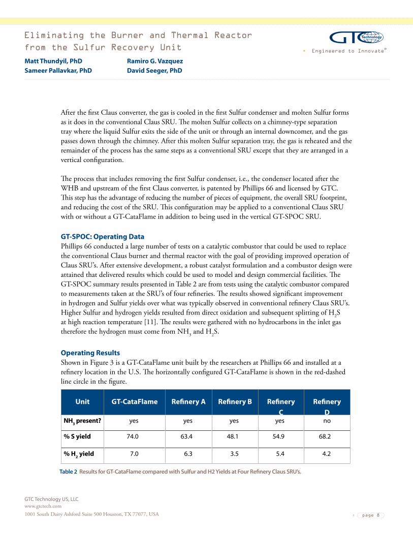
GT-SPOC: Operating DataPhillips66conductedalargenumberoftestsonacatalyticcombustorthatcouldbeusedtoreplacethe conventional Claus burner and thermal reactor with the goal of providing improved operation of ClausSRU’s.Afterextensivedevelopment,arobustcatalystformulationandacombustordesignwereattained that delivered results which could be used to model and design commercial facilities. The GT-SPOCsummaryresultspresentedinTable2arefromtestsusingthecatalyticcombustorcomparedtomeasurementstakenattheSRU’soffourrefineries.TheresultsshowedsignificantimprovementinhydrogenandSulfuryieldsoverwhatwastypicallyobservedinconventionalrefineryClausSRU’s.HigherSulfurandhydrogenyieldsresultedfromdirectoxidationandsubsequentsplittingofH2S athighreactiontemperature[11].TheresultsweregatheredwithnohydrocarbonsintheinletgasthereforethehydrogenmustcomefromNH3 and H2S.
Operating ResultsShowninFigure3isaGT-CataFlameunitbuiltbytheresearchersatPhillips66andinstalledatarefinerylocationintheU.S.ThehorizontallyconfiguredGT-CataFlameisshowninthered-dashedline circle in the figure.
Unit GT-CataFlame Refinery A Refinery B Refinery C
Refinery D
NH3 present? yes yes yes yes no
% S yield 74.0 63.4 48.1 54.9 68.2
% H2 yield 7.0 6.3 3.5 5.4 4.2
Table 2 Results for GT-CataFlame compared with Sulfur and H2 Yields at Four Refinery Claus SRU’s.

Engineered to Innovate®
Eliminating the Burner and Thermal Reactor
from the Sulfur Recovery Unit
GTC Technology US, LLC www.gtctech.com 1001 South Dairy Ashford Suite 500 Houston, TX 77077, USA page 9
Matt Thundyil, PhDSameer Pallavkar, PhD
Ramiro G. VazquezDavid Seeger, PhD
The GT-CataFlame operated successfully, and testing was performed to identify the operating parametersandcatalystformulationthatresultedin:
1. The highest H2S conversion to Sulfur,
2.ProducingthenecessaryamountofSO2 for the downstream Claus converters, 3.Theleastamountofunwantedbyproductformation,primarilyCOSandCS2, 4.Thedestructionofammonia,and 5. Formation of H2andCO,ratherthananyunwantedhydrocarbonbyproducts.
TheresultsinFigure4showtheperformanceofthecatalystthatwasevaluatedforanextended period of time in the GT-CataFlame unit. During this period, air-to-H2S ratios and gas velocities were being evaluated, so throughout the duration of the testing these parameters were varied to observe the effects and to arrive at optimum operating conditions. However, even though conditions were changed H2S conversion and selectivity towards forming elemental Sulfur remained high throughout the period. At certain points the data reflect operating conditions that achieve the best H2S conversion and Sulfur yield so those operating conditions will be used for commercial unit design and operation.
Figure 3 GT-CataFlame Equipment Installed at a Refinery in the United States.

Engineered to Innovate®
Eliminating the Burner and Thermal Reactor
from the Sulfur Recovery Unit
GTC Technology US, LLC www.gtctech.com 1001 South Dairy Ashford Suite 500 Houston, TX 77077, USA page 10
Matt Thundyil, PhDSameer Pallavkar, PhD
Ramiro G. VazquezDavid Seeger, PhD
Throughoutthetestperiodtherangeofgascompositionwasapproximately80-82mol%H2S, 11 -12mol%CO2,5-6mol%water,and1mol%hydrocarboncontent;theremaining1-2mol%isnitrogen and the typical analytical measurement error.
Theresultsindicatethatover80%oftheH2Swasconvertedwithapproximately69-70%yieldofelemental Sulfur, the remainder was as unreacted H2SandSO2,andlessthan1%formationofCOSand CS2combined.Inadditiontherewasanaverage7%yieldofH2. This performance was better thanthatofaconventionalClausburnerandthermalreactorwhere50–70%oftheinletH2S is convertedandtheelementalSulfuryieldis40–65%oftheinletSulfur.
GT-CataFlame and GT-SPOC AdvantagesBasedupontheresultsoftheGT-CataFlameunitthathavebeenpresentedhereandpreviously[10],several process and economic advantages have been identified from having a short-contact-time catalytic combustorversusaClausburnerandthermalreactor.Theadvantagesaresummarizedbelowandexplainedinmoredetailinthefollowingsections.
Figure 4 Results of H2S Conversion, Sulfur Yield and Hydrogen Concentration in the Outlet Gas for
900 Hours of Testing at Various Operating Conditions for the GT-CataFlame Unit.
Engineered to Innovate®
Eliminating the Burner and Thermal Reactor
from the Sulfur Recovery Unit
GTC Technology US, LLC www.gtctech.com 1001 South Dairy Ashford Suite 500 Houston, TX 77077, USA page 11
Matt Thundyil, PhDSameer Pallavkar, PhD
Ramiro G. VazquezDavid Seeger, PhD
Process Advantages • Sincethereactantsarepre-mixedpriortopassingthroughtheGT-CataFlamecombustor,the
reaction is uniform through the cross section of the high-temperature catalyst eliminating the problemsofpost-combustionmixingintheClausthermalreactorforcontaminantdestruction.
• Close-couplingoftheGT-CataFlamecatalystzoneandtheWHBimprovesoverallSulfuryieldand reduces the air requirement due to rapid reaction quenching. This eliminates the oxygenbreakthroughproblemsthatroutinelyoccurinClausunits.
• Noflames,fire-eyes,norburnermanagementsystemsarerequired.Asmallretractableburner or access to a hydrogen containing fuel is all that is needed to trigger the catalyst at startup.
• Fuelgasoxidationforwarmuptakesplaceat25%airstoichiometryeliminatingoxygen breakthroughtodownstreamClausconverterbedsduringstartupandshutdown.
• LowmolecularweighthydrocarbonsareconvertedtoreductionTailGasUnit(TGU)friendlyH2andCObycatalyticpartialoxidation.Sootformationiseliminated.Air/fuelratiosfor fuelgasoxidationareveryclosetotheacidgas/airratiosmakingswitchingbetweenthetwo nearly seamless.
• COSandCS2 formation are significantly reduced. • TheSulfurproductcontainsonly25-33%ofthedissolvedH2S and sulphanes of normal
Claus Sulfur, reducing the need for large Sulfur degassing units.
Economic Advantages • GT-CataFlamerequiressignificantlylessrefractoryliningcomparedtotheconventionalClaus
thermal reactor. • SmallGT-CataFlamecombustorvolumeandreductionofbyproductsallowsfordesignchanges
reducingoverallSRUfootprint. • TheClausplantcanbeconstructedinaverticalorientationwheretheunitisself-draining. • TheverticalGT-SPOCdesigneliminatessomeinterconnectingpipingandSulfurrundown
piping and equipment. • BecauseGT-CataFlameissmallerthanatypicalburnerandthermalreactor,thereisless
refractory and catalyst mass to heat up or cool down; this in turn reduces the time required for shutdown or startup.
• ThefirstSulfurcondenserandre-heaterthatislocateddownstreamoftheWHBmayalsobeeliminated,sothatthegasstreamexitingtheWHBflowsdirectlytothefirstClausreactorstage.Eliminating this equipment is a significant capital reduction.
COS and CS2 Reduction and Implications for Claus Converter Bed DesignThebestmethodtominimizetheeffectsofhydrocarboncontaminationofacidgasesinanySRUistopreventhydrocarbonabsorptionintheacidgasremovalsystem(byusingsluganddropcatchingdrums,aerosoldropletremoval,andleanamine/sourgasdifferentialtemperaturecontrol)andmitigatehydrocarbonaccumulation(byusingrichflashdrumswithskimmingandgasremoval,carbonfiltration,andregeneratorrefluxpurge).Despitetheseefforts,hydrocarbonmaygetintotheacidgas
Engineered to Innovate®
Eliminating the Burner and Thermal Reactor
from the Sulfur Recovery Unit
GTC Technology US, LLC www.gtctech.com 1001 South Dairy Ashford Suite 500 Houston, TX 77077, USA page 12
Matt Thundyil, PhDSameer Pallavkar, PhD
Ramiro G. VazquezDavid Seeger, PhD
leadingtoaproductionoftheundesiredbyproducts,COSandCS2.Nominallythebyproductsresultfromreactingaftertheflamemixingzonewherehot,oxygen-freeflamebyproductscanmixwithunburned hydrocarbons and form sulfur, e.g., CH4 and S2,intheacidgasesasinatypical1/3-2/3split flow burner and thermal reactor for leaner H2Scontentgases.[14]SincethegasesflowingtotheGT-CataFlamecombustorarepre-mixedandpreheatedthetemperatureishotterthanthatofathermalreactor(CataFlameisapproximately2200to2300°F).Also,sincetheresidencetimefromthecatalystreactortoWHBisafractionofasecond,lessCOSandCS2 will form as compared to a conventional Claus unit. Data from the GT-CataFlame unit operations confirms a significant reductionintheamountofbyproductCOSandCS2.
Astudyof24gasplantswithabroadrangeofinletH2S concentration in the gas passing to the Claus burnerandthermalreactorshowedthattheCOSandCS2concentrationinthegasexitingtheWHBwasintherangeof0.06–1.7mol%forCOSand0.01–1.1mol%forCS2.[13]AttheoptimizedoperatingconditionsfortheGT-CataFlameunit,0.12–0.18mol%COSand0.36–0.48mol%CS2 were measured in the gas leaving the catalytic combustor.
Also,sinceCOSandCS2 formation is significantly decreased, and the first Claus converter conditionswillbehotterthanaconventionalClausSRUdesign,theClausconverterfollowingtheGT-CataFlamecombustorcanbemuchsmallerhelpingtoreducetheClauscatalystbedsizeandallowingforamorecompactfootprint.InGT-SPOCthefirstClausconvertermaybehotterthaninaconventionalClausdesignifthegasoutoftheWHBflowsdirectlytotheClausconverterwithoutbeing cooled first in a Sulfur condenser.
Acid Gas Concentration RequirementStable operation of the GT-CataFlame catalyst was demonstrated at acid gas concentrations as lowas25%H2S using only preheated air and preheated acid gas. A wide range of tests were conducted on lean H2SstreamscontainingCO2 or nitrogen diluents and typical light hydrocarbon components. Sulfur yield varied with H2S concentration, but the yield was still close to equilibrium computations,unlikeleanacidgasClausunitsthatproducelittletonoSulfurfromthethermal stage. The GT-CataFlame unit located at the refinery in the U.S. confirmed the results obtained in the laboratory.
Turndown Testingshowedthatoperationswerestabledownto25%turndownwhenoperatingwithjustacidgases.Hypothetically,theGT-CataFlameunitiscapableofoperatingwithanymixturebetweenpurenatural gas and pure H2Ssincethestoichiometricratioforair-to-reactantisintherangeof2.2–2.5forbothnaturalgasandacidgas.Theplantdatawasrunataslowas12%turndownwithminimaleffectonperformance.Becauseoftheabilitytooperatewithnearlyanyratiooffuelgastoacidgas,even lower turndown rates can be achieved.

Engineered to Innovate®
Eliminating the Burner and Thermal Reactor
from the Sulfur Recovery Unit
GTC Technology US, LLC www.gtctech.com 1001 South Dairy Ashford Suite 500 Houston, TX 77077, USA page 13
Matt Thundyil, PhDSameer Pallavkar, PhD
Ramiro G. VazquezDavid Seeger, PhD
Air Demand and Related Operational ImprovementsWhile the overall recovery of Sulfur will fluctuate significantly with air-to-acid gas ratios in both theClausandGT-SPOCprocesses,theGT-CataFlamecatalystselectivityforSulfurdoesnotvarysignificantly over a wide range of air-to-H2S ratios.
Thecombinationofpre-mixingbeforereactionandclosecouplingofthereactortotheWHBaidsbothhydrogenformationreactions(partialoxidationanddissociation)andinhibitsthemainhydrogenconsumptionreaction(recombinationofH2andS).AstheflowrateincreasesintheGT-CataFlameunit,improvedheattransferduetohigherReynoldsnumberandthermalconductivityofthegas(duetohigherhydrogencontent)appeartoaidininhibitingrecombinationofH2 and S. This translates to more capacity with less overall pressure drop.
Startup and Shutdown Operating ImprovementsMost of the time starting up a Claus plant is spent heating up the large amount of refractory in the thermal reactor chamber and catalyst in the catalyst beds. The GT-CataFlame combustor is very compactandincloseproximitytothewasteheatboilerentrance,sothereisaminimumamountofrefractory to be dried and heated to operating temperature.
The small amount of catalyst and support materials in the GT-CataFlame combustor is easily heated up by a small preheater such as a STACKMATCH® eliminating one of the biggest problems in starting up or recovering from a shutdown, i.e., relighting the main burner. It was shown that hydrogen rich gases(~40%H2)andairmixturescanbecatalyticallyignitedbytheGT-CataFlamecatalystpotentiallybypassing the need for any type of fired preheater.
MinimizingtheformationofcontaminantssuchasCOSandCS2 and operating the first catalyst bed directlyafterWHBmakesitpossibletoreducetheamountofClauscatalystneededspeedingupboththeshut-downprocess(Sulfurremovalorheatsoak)andthestart-upprocess(warmup).EliminationoftheSulfurcondenserfollowingtheWHBandsubsequentreheatereliminatescooldownorwarmup of equipment and interconnecting piping, again speeding up the shut-down or start-up process.
When heating up or cooling down a Claus plant, fuel gas is used at near the stoichiometric ratio with air.WhentheClauscatalystisSulfur-laden,itneedstobe“heatsoaked”,i.e.,operatedata15–30°Chighertemperature,tovaporizeanycondensedsulfurandthusregeneratethecatalystbed.Duringtheseperiodsthatareoftentimesplannedtocoincidewithastartuporshutdown,unreactedexcessoxygenmaypassthroughthefurnaceandcausedamagetothecatalystbedbyoverheatingthebedorcausing sulphation of the catalyst. Sulphation results in the need to regenerate the Claus catalyst by operatingitatanevenhighertemperatureofnear475°C.Theair-to-fuelgasratioformostnaturalgasstreamsrangefrom(9.5-10)-to-1,whiletheair-to-acidgasratioistypicallyinthe(1-2.5)-to-1rangedependingonacidgasconcentration.Thismakesfordifficultswitchingfromonefeedgasto

Engineered to Innovate®
Eliminating the Burner and Thermal Reactor
from the Sulfur Recovery Unit
GTC Technology US, LLC www.gtctech.com 1001 South Dairy Ashford Suite 500 Houston, TX 77077, USA page 14
Matt Thundyil, PhDSameer Pallavkar, PhD
Ramiro G. VazquezDavid Seeger, PhD
another while maintaining accurate air flow control. At the stoichiometric ratio the adiabatic flame temperature(~3500°F)formostfuelgasiswellabovethetemperaturelimitofthermalreactorrefractory(~2800°F)andferrulesrequiringtheincorporationofsteamornitrogendiluenttoholdtheflametemperature to a safe operating range. GT-CataFlame eliminates these problems with its air-to-fuel ratiointherangeof2.2–2.5,whichisthesamerangeasforitsair-to-acidgasratio.
A slightly sub-stoichiometric flame in the Claus burner has a tendency to form soot which can rapidly plug the catalyst bed downstream of the burner. GT-CataFlame catalyst can convert fuel gasviapartialoxidationwithanair-to-fuelratiointherangeof2.2-2.5sothatnosootisformed. Inadditionthecatalystcontainscomponentsthatresisttheformationofcokeonthecatalyst surfacewhichresultsinlessproductionofsoot.GT-CataFlameeliminatesthedifficultiesof switching between operating with fuel gas and operating with acid gas.
FiringnearstoichiometricwithaircanresultinsomeoxygenpassingthroughtotheClaus converterscausingunwantedcatalystexothermsdamagingboththecatalystsandthevessels. Since GT-CataFlame catalyst does not have to be operated near the stoichiometric air-to-fuel ratio, theexothermsthatwouldnormallydamagethedownstreamClauscatalystsareeliminated.
In general, the more frequent the shutdown and startup of a Claus unit, the more problems that can beexpected.DuringtheGT-CataFlameunit’slong-termcatalystevaluationstheunitwasshutdownand started up over 30 times. Through all of the startups and shutdowns the GT-CataFlame catalyst retained its original activity.
Reduction of H2S and Sulphanes in the Produced Sulfur The results from the GT-CataFlame operating data show that the Sulfur produced in the first downstream Sulfur condenser contains less dissolved H2Sandsulphanes(H2Sx)thanistypically measuredinaconventionalClausSRU.TheresultsinTable3showthedifferenceinH2S and H2Sxcontent as the Sulfur from the Sulfur condenser immediately following GT-CataFlame contains five to sixtimesmoredissolvedH2S and H2SxasSulfurfromthecondenserthatfollowsbothGT-CataFlameand the first stage Claus converter.
After GT-CataFlame
After GT-CataFlame & One Claus Stage
% Sulfur Yield 72.3 85.8
H2S in Sulfur, ppmw (FTIR) 308.4 60.3
H2Sx in Sulfur, ppmw (FTIR) 340.1 54.2
Table 3 Reduction of H2S and H2Sx in Sulfur Produced by GT-SPOC.

Engineered to Innovate®
Eliminating the Burner and Thermal Reactor
from the Sulfur Recovery Unit
GTC Technology US, LLC www.gtctech.com 1001 South Dairy Ashford Suite 500 Houston, TX 77077, USA page 15
Matt Thundyil, PhDSameer Pallavkar, PhD
Ramiro G. VazquezDavid Seeger, PhD
Aspreviouslydiscussed,inGT-SPOCtheSulfurcondenserimmediatelyfollowingtheWHBhasbeen eliminated as well as the first re-heater immediately following that condenser. Therefore, the gas exitingtheWHBflowsimmediatelyintothefirstClauscatalystbedwheremoreH2S is converted toSulfursothatapproximately90%oftheH2S is converted by the time the gas reaches the first Sulfur condenser. At the point where the first molten Sulfur is produced there is a significantly lower H2S partial pressure in the gas than would normally be found in the first Sulfur condenser in a conventionalClausSRU,resultinginreducedH2S dissolved in the produced molten Sulfur. In essence,inGT-SPOCtheH2S partial pressure that is measured in the gas in the first condenser is what would normally be found at the second condenser of a conventional Claus unit.
Capital Cost ComparisonAn independent engineering firm performed a cost study that compared the capital cost of a two stageGT-SPOCunittoaconventionaltwostageClausunitwithaburnerandthermalreactor. TheGT-SPOCSRUwasdesignedinthesingle,verticaltowerarrangementasshowninFigure2.The amine unit, the TGU and the Sulfur pit were assumed to be similar for both units and were not includedinthecapitalcostestimate.ThereforeanycostadvantageoftheGT-SPOCeffectsofreducedduty on the TGU and less H2S and H2SxdissolvedintheSulfurarenotincludedinthecomparison.The cost study was prepared using the standard engineering cost factors based on U.S. Gulf Coast prices.
Design BasisThe composition of the acid gas flowing to the GT-CataFlame or to the Claus burner is shown in Table4.ForpurposesofpresentationintheTable,theacidgasandSourWaterStripper(SWS)offgasare added together and reported as the composition of one stream as they would be in the case of the feedgastotheGT-SPOCSRU.However,inthecaseofaconventionalClausstreamtheSWSoff gas is added to the burner and the acid gas is operated in split flow.
TheflowrateofthecombinedacidgasandSWSoffgasis4,290Nm3/h(3.8MMscfd)andthe Sulfurproductionrateisapproximately100MTPD.
Cost Comparison ResultsTheresultsofthiscostestimateindicatedthattheGT-SPOCunitisapproximately20%lessthanthecapital cost of a conventional Claus unit. A few major differences between the two processes are the reasonsforthesavings:
• TheGT-CataFlamecombustorisapproximately20%ofthevolumeofanequivalentClausburner and thermal reactor;
• GT-CataFlamerequiresmuchlessrefractory(aslittleas1/40ththeamountrequiredfora conventionalClausburnerandthermalreactor);

Engineered to Innovate®
Eliminating the Burner and Thermal Reactor
from the Sulfur Recovery Unit
GTC Technology US, LLC www.gtctech.com 1001 South Dairy Ashford Suite 500 Houston, TX 77077, USA page 16
Matt Thundyil, PhDSameer Pallavkar, PhD
Ramiro G. VazquezDavid Seeger, PhD
• TheSulfurcondenserlocatedaftertheWHBandbeforethefirstClausconverterinaconventionalClausSRUiseliminatedineithertheverticalorhorizontalGT-SPOCSRUdesigns;
• ThefirstreheaterthatfollowsthefirstSulfurcondenserinaconventionalClausSRUisalsoeliminatedasitisunnecessaryinGT-SPOC;and
• InterconnectingpipingisreducedinGT-SPOCasthestagesareclosecoupledinaverticalarrangementascomparedtheconventionalClausSRU.
SummaryConventional“modifiedClaus”technologywithafree-flamethermalsectioniswellknowntohaveanumber of operating challenges associated with the reactions that occur in the flame and the thermal reactor. An alternate, proven approach was presented here, where the free-flame thermal section is replacedwithacatalyticcombustorthatutilizesadurablecatalystthatenablesSulfurpartial oxidationcatalysis.ThischangeatthefrontendofaconventionalClausprocessresultsinsignificantprocessandeconomicadvantagesincludingimprovedSulfuryield,reductionsinCOSandCS2 formation, reduced impact of hydrocarbons on air demand, improved start-up and shut-down operations,andreductionsintheClausconvertercatalystbedsections.Overall,GT-CataFlame allowsupgradesofagingClausburnersandthermalreactors,andenablesa20–30%reductionincapital costs associated with Claus plants, while reducing the Tail Gas Unit load due to its higher conversionefficiencies.GT-SPOCprovidestheadditionaladvantagesofreducingthenumberofpieces of equipment and reduced interconnecting piping in the vertical arrangement.
InadditiontoGT-CataFlameandGT-SPOC,GTCTechnologyisalsotheexclusivelicensorofGT-DOS™adirectoxidationtechnologyforremovalofH2S from dilute H2S-containing gas streams.
Component Mole % Component Mole %
CO2 0.20 nC4 0.00
H2S 67.80 nC5 0.02
C1 0.11 nC6 0.00
C2 0.09 H2O 19.80
C3 0.02 NH3 11.94
iC4 0.00 H2 0.05
Table 4 Composition of the Acid Gas Flowing to the GT-CataFlame Combustor for the Capital
Cost Comparison of GT-SPOC and Conventional Claus SRU’s.
Engineered to Innovate®
Eliminating the Burner and Thermal Reactor
from the Sulfur Recovery Unit
GTC Technology US, LLC www.gtctech.com 1001 South Dairy Ashford Suite 500 Houston, TX 77077, USA page 17
Matt Thundyil, PhDSameer Pallavkar, PhD
Ramiro G. VazquezDavid Seeger, PhD
References 1.US6,403,051RecoveryofSulfurfromH2SandConcurrentProductionofH2UsingShortContactTimeReactors.2.US6,579,510SPOXEnhancedProcessforProductionofSynthesisGas.3.US6,800,269ShortContactTimeCatalyticSulfurRecoverySystemforRemovingH2SfromaWasteGasStream.4.US6,946,111ShortContactTimePartialOxidationProcessforRecoveringSulfurfromanH2SContainingGasstream.5.US7,122,170CatalystsforGT-SPOC™EnhancedSynthesisGasProduction.6.US7,138,101TwoStageCatalyticProcessforRecoveringSulfurfromanH2SContainingGasStream.7.US7,226,572CompactSulfurRecoveryPlantandProcess.8.US7,326,397CatalyticPartialOxidationProcessforRecoveringSulfurfromanH2SContainingStream.9.US7,357,908ApparatusandCatalyticPartialOxidationProcessforRecoveringSulfurfromanH2SContainingGasStream.10. Is There “Direct Oxidation” of H2S to Sulfur? Keller, A., Laurance Reid Gas Conditioning Conference, February 2009.11. Partial Oxidation of H2S to Sulfur, a Claus Alternative, British Sulfur Conference,October2003.12. Sulfur Recovery,Paskall,H.G.andSames,J.A.,13thEdition,2010,p.1-14.13. Sulfur Recovery,Paskall,H.G.andSames,J.A.,13thEdition,2010,p.2-80.14.New Insights into the Claus Thermal Stage, Chemistry and Temperatures,Borsboom,H.,Clark,P.,Goar,B.G.,Laurance Reid
Gas Conditioning Conference, February 2009.
GTC’s gas processing and Sulfur technology portfolio is focused on delivering solutions for acid gas removal, Sulfur recovery, dehydration, and liquids recovery from a variety of process gas streams to meetveryspecificcustomerneeds.GTCutilizesthesetechnologiestodeliverrobustandreliable custom solutions for challenging applications across multiple industries. These technologies are deliveredinavarietyofwaysincludinglicensewithabasicengineeringpackageorviaanEngineering,ProcurementandConstructionmanagement(EPCm)project.Ourbroadportfolioofproductsandextensiveexperienceenablesclientstoseamlesslyintegrateourprocessesacrossbusinesslines.