guardian english 71569212 08-11 - flowserve · guardian user instructions english 71569212 08-11...
TRANSCRIPT

USER INSTRUCTIONS
Page 1 of 68
Guardian Sealless Metallic Pumps ANSI Standard, Close-Coupled and Unitized Self-Primer
Single stage, end suction, centrifugal, chemical process pumps
PCN=71569212 08-11 (E) (Based on P-20-502.) Original instructions.
Installation Operation
Maintenance
These instructions must be read prior to installing , operating, using and maintaining this equipment.

GUARDIAN USER INSTRUCTIONS ENGLISH 71569212 08-1 1
Page 2 of 68 flowserve.com
CONTENTS Page
Page
1 INTRODUCTION AND SAFETY......................3 1.1 General .........................................................3 1.2 CE marking and approvals ...........................3 1.3 Disclaimer .....................................................3 1.4 Copyright.......................................................3 1.5 Duty conditions .............................................3 1.6 Safety............................................................4 1.7 Nameplate and warning labels .....................8 1.8 Specific machine performance......................8 1.9 Noise level ....................................................8
2 TRANSPORT AND STORAGE........................9 2.1 Consignment receipt and unpacking..............9 2.2 Handling........................................................9 2.3 Lifting.............................................................9 2.4 Storage........................................................10 2.5 Recycling and end of product life................11
3 DESCRIPTION...............................................11 3.1 Configurations.............................................11 3.2 Nomenclature..............................................11 3.3 Design of major parts..................................12 3.4 Performance and operation limits ...............13
4 INSTALLATION..............................................16 4.1 Location ......................................................16 4.2 Part assemblies ..........................................16 4.3 Foundation ..................................................16 4.4 Grouting ......................................................18 4.5 Initial alignment ...........................................19 4.6 Piping ..........................................................20 4.7 Electrical connections .................................27 4.8 Final shaft alignment check ........................28 4.9 Protection systems......................................28
5 COMMISSIONING, STARTUP, OPERATION AND SHUTDOWN .........................................30
5.1 Pre-commission procedure.........................30 5.2 Pump lubricants ..........................................30 5.3 Impeller clearance.......................................31 5.4 Direction of rotation.....................................32 5.5 Guarding .....................................................32 5.6 Priming and auxiliary supplies ....................33 5.7 Starting the pump........................................34 5.8 Running or operation ..................................34 5.9 Stopping and shutdown ..............................34 5.10 Hydraulic, mechanical and electrical duty
35
6 MAINTENANCE.............................................35 6.1 Maintenance schedule................................36 6.2 Spare parts .................................................36 6.3 Recommended spares and consumables ..37 6.4 Tools required.............................................37 6.5 Fastener torques ........................................37 6.6 Setting impeller clearance ..........................37 6.7 Disassembly ...............................................38 6.8 Examination of parts...................................44 6.9 Assembly of pump......................................47
7 FAULTS; CAUSES AND REMEDIES............56
8 PARTS LIST AND DRAWINGS.....................59 8.1 Cutaway – Guardian G & H Series – Group 1 –
long coupled ...............................................59 8.2 Cutaway - Guardian G & H Series - Group 2 –
long coupled ...............................................61 8.3 Cutaway - Guardian G & H Series - Group 1 –
close coupled..............................................63
9 CERTIFICATION ...........................................65
10 OTHER RELEVANT DOCUMENTATION AND MANUALS......................................................65
10.1 Supplementary User Instructions .......65 10.2 Change notes .....................................65 10.3 Additional sources of information.......65

GUARDIAN USER INSTRUCTIONS ENGLISH 71569212 08-1 1
Page 3 of 68 flowserve.com
1 INTRODUCTION AND SAFETY 1.1 General
These instructions must always be kept close to the product's operating location or directly with the product. Flowserve products are designed, developed and manufactured with state-of-the-art technologies in modern facilities. The unit is produced with great care and commitment to continuous quality control, utilising sophisticated quality techniques, and safety requirements. Flowserve is committed to continuous quality improvement and being at service for any further information about the product in its installation and operation or about its support products, repair and diagnostic services. These instructions are intended to facilitate familiarization with the product and its permitted use. Operating the product in compliance with these instructions is important to help ensure reliability in service and avoid risks. The instructions may not take into account local regulations; ensure such regulations are observed by all, including those installing the product. Always coordinate repair activity with operations personnel, and follow all plant safety requirements and applicable safety and health laws/regulations.
These instructions must read prior to installing, operating, using and maintaining the equipment in any region worldwide. The equipment must not be put into service until all the conditions relating to safety noted in the instructions, have been met. Failure to follow and apply the present user instructions is considered to be misuse. Personal injury, product damage, delay or failure caused by misuse are not covered by the Flowserve warranty. 1.2 CE marking and approvals It is a legal requirement that machinery and equipment put into service within certain regions of the world shall conform with the applicable CE Marking Directives covering Machinery and, where applicable, Low Voltage Equipment, Electromagnetic Compatibility (EMC), Pressure Equipment Directive (PED) and Equipment for Potentially Explosive Atmospheres (ATEX).
Where applicable, the Directives and any additional Approvals, cover important safety aspects relating to machinery and equipment and the satisfactory provision of technical documents and safety instructions. Where applicable this document incorporates information relevant to these Directives and Approvals. To confirm the Approvals applying and if the product is CE marked, check the serial number plate markings and the Certification, (See section 9, Certification.) 1.3 Disclaimer Information in these User Instructions is believed to be complete and reliable. However, in spite of all of the efforts of Flowserve Corporation to provide comprehensive instructions, good engineering and safety practice should always be used. Flowserve manufactures products to exacting International Quality Management System Standards as certified and audited by external Quality Assurance organisations. Genuine parts and accessories have been designed, tested and incorporated into the products to help ensure their continued product quality and performance in use. As Flowserve cannot test parts and accessories sourced from other vendors the incorrect incorporation of such parts and accessories may adversely affect the performance and safety features of the products. The failure to properly select, install or use authorised Flowserve parts and accessories is considered to be misuse. Damage or failure caused by misuse is not covered by the Flowserve's warranty. In addition, any modification of Flowserve products or removal of original components may impair the safety of these products in their use. 1.4 Copyright All rights reserved. No part of these instructions may be reproduced, stored in a retrieval system or transmitted in any form or by any means without prior permission of Flowserve Pump Division. 1.5 Duty conditions This product has been selected to meet the specifications of your purchaser order. The acknowledgement of these conditions has been sent separately to the Purchaser. A copy should be kept with these instructions.
The product must not be operated beyond the parameters specified for the application. If there is any doubt as to the suitability of the product for the application intended, contact Flowserve for advice, quoting the serial number.
GUARDIAN USER INSTRUCTIONS ENGLISH 71569212 08-1 1
Page 4 of 68 flowserve.com
If the conditions of service on your purchase order are going to be changed (for example liquid pumped, temperature or duty) it is requested that the user seek written agreement of Flowserve before start up. 1.6 Safety 1.6.1 Summary of safety markings These User Instructions contain specific safety markings where non-observance of an instruction would cause hazards. The specific safety markings are:
This symbol indicates electrical safety instructions where non-compliance will involve a high risk to personal safety or the loss of life.
This symbol indicates safety instructions where non-compliance would affect personal safety and could result in loss of life.
This symbol indicates “hazardous and toxic fluid” safety instructions where non-compliance would affect personal safety and could result in loss of life.
This symbol indicates safety instructions where non-compliance will involve some risk to safe operation and personal safety and would damage the equipment or property.
This symbol indicates “strong magnetic field” safety instructions where non-compliance would affect personal safety, pacemakers, instruments, or stored data sensitive to magnetic fields.
This symbol indicates explosive atmosphere zone marking according to ATEX. It is used in safety instructions where non-compliance in the hazardous area would cause the risk of an explosion.
This symbol is used in safety instructions to remind not to rub non-metallic surfaces with a dry cloth; ensure the cloth is damp. It is used in safety instructions where non-compliance in the hazardous area would cause the risk of an explosion.
This sign is not a safety symbol but indicates an important instruction in the assembly process. 1.6.2 Personnel qualification and training All personnel involved in the operation, installation, inspection and maintenance of the unit must be qualified to carry out the work involved. If the personnel in question do not already possess the necessary knowledge and skill, appropriate training and instruction must be provided. If required the
operator may commission the manufacturer/supplier to provide applicable training. Always coordinate repair activity with operations and health and safety personnel, and follow all plant safety requirements and applicable safety and health laws and regulations. 1.6.3 Safety action This is a summary of conditions and actions to prevent injury to personnel and damage to the environment and to equipment. For products used in potentially explosive atmospheres section 1.6.4 also applies.
HIGH MAGNETIC FIELDS Great care should be taken when assembling/ dismantling magnetic rotors, where fitted, because of the very high forces which can be created by the magnets. Persons with pacemakers and any instrumentation etc sensitive to magnetic fields should be kept wel l away from the magnetic drive unit during dismantling.
NEVER DO MAINTENANCE WORK WHEN THE UNIT IS CONNECTED TO POWER
DRAIN THE PUMP AND ISOLATE PIPEWORK BEFORE DISMANTLING THE PUMP The appropriate safety precautions should be taken where the pumped liquids are hazardous.
FLUOROELASTOMERS (When fitted.) When a pump has experienced temperatures over 250 ºC (482 ºF), partial decomposition of fluoroelastomers (example: Viton) will occur. In this condition these are extremely dangerous and skin contact must be avoided.
HANDLING COMPONENTS Many precision parts have sharp corners and the wearing of appropriate safety gloves and equipment is required when handling these components. To lift heavy pieces above 25 kg (55 lb) use a crane appropriate for the mass and in accordance with current local regulations.
NEVER OPERATE THE PUMP WITHOUT THE COUPLING GUARD AND ALL OTHER SAFETY DEVICES CORRECTLY INSTALLED
GUARDS MUST NOT BE REMOVED WHILE THE PUMP IS OPERATIONAL
HOT (and cold) PARTS
GUARDIAN USER INSTRUCTIONS ENGLISH 71569212 08-1 1
Page 5 of 68 flowserve.com
If hot or freezing components or auxiliary heating equipment can present a danger to operators and persons entering the immediate area, action must be taken to avoid accidental contact (such as shielding). If complete protection is not possible, the machine access must be limited to maintenance staff only with clear visual warnings and indicators to those entering the immediate area.
Bearing housings must not be insulated and drive motors and bearings may be hot. If the temperature is greater than 80 °C (175 °F) o r below -5 °C (23 °F) in a restricted zone, or exceeds local regulations, action as above shall be taken.
THERMAL SHOCK Rapid changes in the temperature of the liquid within the pump can cause thermal shock, which can result in damage or breakage of components and should be avoided.
NEVER APPLY HEAT TO REMOVE IMPELLER Trapped lubricant or vapor could cause an explosion.
ALWAYS USE THE JACKBOLTS TO SEPARATE THE POWER END FROM THE WET END ASSEMBLIES
PREVENT EXCESSIVE EXTERNAL PIPE LOAD Do not use pump as a support for piping. Do not mount expansion joints, unless allowed by Flowserve in writing, so that their force, due to internal pressure, acts on the pump flange.
ENSURE CORRECT LUBRICATION (See section 5, Commissioning, startup, operation and shutdown.)
NEVER EXCEED THE MAXIMUM DESIGN PRESSURE (MDP) AT THE TEMPERATURE SHOWN ON THE PUMP NAMEPLATE See section 3 for pressure versus temperature ratings based on the material of construction.
NEVER OPERATE THE PUMP WITH THE DISCHARGE VALVE CLOSED (Unless otherwise instructed at a specific point in the user instructions.) See section 5, Commissioning start-up, operation and shutdown.
NEVER RUN THE PUMP DRY OR WITHOUT PROPER PRIME (Casing Flooded) Operating the magnetic coupling dry may cause
immediate damage to the containment shell and bearings.
NEVER OPERATE THE PUMP WITH THE SUCTION VALVE CLOSED It should be fully opened when the pump is running.
NEVER OPERATE THE PUMP AT ZERO FLOW OR FOR EXTENEDED PERIODS BELOW THE MINIMUM CONTINUOUS FLOW
DO NOT START THE PUMP WITHOUT PROPER LUBRICATION Refer to bearing lubrication in Section 5.2.
THE PUMP SHAFT MUST TURN CLOCKWISE WHEN VIEWED FROM THE MOTOR END It is absolutely essential that the rotation of the motor be checked before installation of the coupling spacer and starting the pump. Incorrect rotation of the pump for even a short period can unscrew the impeller, which can cause significant damage.
GUARDIAN G & H SERIES PUMPS ARE SIZED BASED ON A SPECIFIC APPLICATION. In the event the user elects to operate this pump in a service other than what it was originally sized for, a Flowserve sales engineer should be contacted to evaluate the new application.
DO NOT RUN THE PUMP AT ABNORMALLY HIGH OR LOW FLOW RATES Operating at a flow rate higher than normal or at a flow rate with no back pressure on the pump may overload the motor and cause cavitation. Low flow rates may cause a reduction in pump/bearing life, overheating of the pump, instability and cavitation/vibration.
EXCESSIVE PUMP NOISE OR VIBRATION This may indicate a dangerous condition. The pump must be shut down immediately.
HAZARDOUS LIQUIDS When the pump is handling hazardous liquids care must be taken to avoid exposure to the liquid by appropriate pump placement, limiting personnel access and by operator training. If the liquid is flammable and/or explosive, strict safety procedures must be applied.
GUARDIAN USER INSTRUCTIONS ENGLISH 71569212 08-1 1
Page 6 of 68 flowserve.com
1.6.4 Products used in potentially explosive atmospheres
Measures are required to: • Avoid excess temperature • Prevent build up of explosive mixtures • Prevent the generation of sparks • Prevent leakages • Maintain the pump to avoid hazard The following instructions for pumps and pump units when installed in potentially explosive atmospheres must be followed to help ensure explosion protection. For ATEX, both electrical and non-electrical equipment must meet the requirements of European Directive 94/9/EC. . Always observe the regional legal Ex requirements eg Ex electrical items outside the EU may be required certified to other than ATEX eg IECEx, UL.
1.6.4.1 Scope of compliance
Use equipment only in the zone for which it is appropriate. Always check that the driver, drive coupling assembly, and pump equipment are suitably rated and/or certified for the classification of the specific atmosphere in which they are to be installed. Where Flowserve has supplied only the bare shaft pump, the Ex rating applies only to the pump. The party responsible for assembling the pump set shall select the coupling, driver, and any additional equipment, with the necessary CE Certificate/ Declaration of Conformity establishing it is suitable for the area in which it is to be installed. The output from a variable frequency drive (VFD) can cause additional heating effects in the motor. On pump sets controlled by a VFD, the ATEX Certification for the motor must state that it covers the situation where electrical supply is from the VFD. This particular requirement still applies even if the VFD is in a safe area.
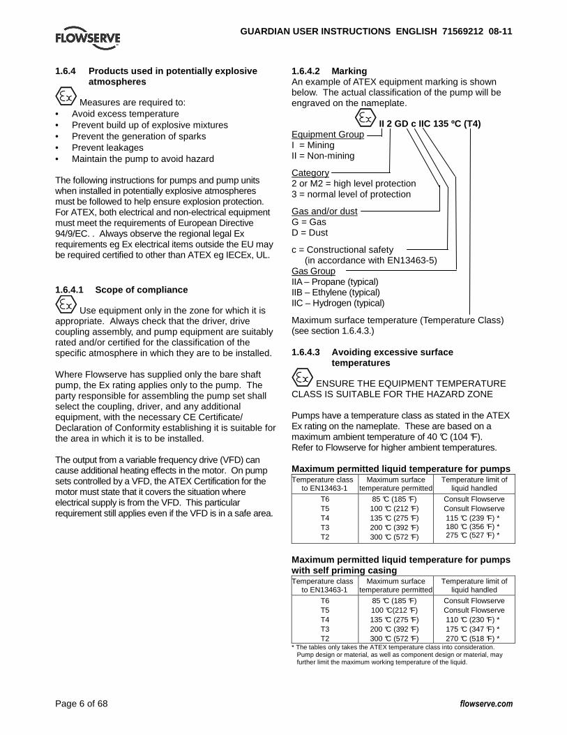
1.6.4.2 Marking An example of ATEX equipment marking is shown below. The actual classification of the pump will be engraved on the nameplate.
II 2 GD c IIC 135 ºC (T4) Equipment Group I = Mining II = Non-mining
Category 2 or M2 = high level protection 3 = normal level of protection
Gas and/or dust G = Gas D = Dust
c = Constructional safety (in accordance with EN13463-5)
Gas Group IIA – Propane (typical) IIB – Ethylene (typical) IIC – Hydrogen (typical)
Maximum surface temperature (Temperature Class) (see section 1.6.4.3.) 1.6.4.3 Avoiding excessive surface
temperatures
ENSURE THE EQUIPMENT TEMPERATURE CLASS IS SUITABLE FOR THE HAZARD ZONE Pumps have a temperature class as stated in the ATEX Ex rating on the nameplate. These are based on a maximum ambient temperature of 40 °C (104 °F). Refer to Flowserve for higher ambient temperatures. Maximum permitted liquid temperature for pumps Temperature class
to EN13463-1 Maximum surface
temperature permitted Temperature limit of
liquid handled
T6 T5 T4 T3 T2
85 °C (185 °F) 100 °C (212 °F) 135 °C (275 °F) 200 °C (392 °F) 300 °C (572 °F)
Consult Flowserve Consult Flowserve 115 °C (239 °F) * 180 °C (356 °F) * 275 °C (527 °F) *
Maximum permitted liquid temperature for pumps with self priming casing Temperature class
to EN13463-1 Maximum surface
temperature permitted Temperature limit of
liquid handled
T6 T5 T4 T3 T2
85 °C (185 °F) 100 °C(212 °F) 135 °C (275 °F) 200 °C (392 °F) 300 °C (572 °F)
Consult Flowserve Consult Flowserve 110 °C (230 °F) * 175 °C (347 °F) * 270 °C (518 °F) *
* The tables only takes the ATEX temperature class into consideration. Pump design or material, as well as component design or material, may further limit the maximum working temperature of the liquid.

GUARDIAN USER INSTRUCTIONS ENGLISH 71569212 08-1 1
Page 7 of 68 flowserve.com
The responsibility for compliance with the specified maximum liquid temperature is with the plant operator. Temperature classification “Tx” is used when the liquid temperature varies and the pump could be installed in different hazardous atmospheres. In this case the user is responsible for ensuring that the pump surface temperature does not exceed that permitted in the particular hazardous atmosphere. Do not attempt to check the direction of rotation with the coupling spacer fitted due to the risk of severe contact between rotating and stationary components. Where there is any risk of the pump being run against a closed valve generating high liquid and casing external surface temperatures fit an external surface temperature protection device. Avoid mechanical, hydraulic or electrical overload by using motor overload trips or a power monitor and perform routine vibration monitoring. In dirty or dusty environments, make regular checks and remove dirt from areas around close clearances, bearing housings and motors. Additional requirements for self-priming casing pumps Where the system operation does not ensure control of priming, as defined in the User Instructions, and the maximum permitted surface temperature of the T Class could be exceeded, the user shall install an external surface temperature protection device. 1.6.4.4 Preventing the build up of explosive
mixtures
ENSURE PUMP IS PROPERLY FILLED AND VENTED AND DOES NOT RUN DRY Ensure that the pump and relevant suction and discharge piping is totally filled with liquid at all times during the pumps operation so that an explosive atmosphere is prevented. In addition, it is essential to make sure that any heating and cooling systems are properly filled. If the operation of the system can not avoid this condition fit an appropriate dry run protection device (example: liquid detection or a power monitor). To avoid potential hazards from fugitive emissions of vapor or gas to atmosphere, the surrounding area must be well ventilated.
1.6.4.5 Preventing sparks
To prevent a potential hazard from mechanical contact, the coupling guard must be non-sparking for category 2 equipment. To avoid the potential hazard from random induced current generating a spark, the baseplate must be properly grounded.
Avoid electrostatic charge. Do not rub non-metallic surfaces with a dry cloth; ensure the cloth is damp. For ATEX the coupling must be selected to comply with 94/9/EC. Correct alignment must be maintained. Additional requirements for pumps on non-metallic baseplates When metallic components are fitted on a non-metallic baseplate they must be individually earthed. 1.6.4.6 Preventing leakage
The pump must only be used to handle liquids for which it has been approved to have the correct corrosion resistance. Avoid entrapment of liquid in the pump and associated piping due to closing of suction and discharge valves, which could cause dangerous excessive pressures to occur if there is heat input to the liquid. This can occur if the pump is stationary or running. Bursting of liquid containing parts due to freezing must be avoided by draining or protecting the pump and auxiliary systems. Where there is the potential hazard of a loss of external flush, the fluid must be monitored. If leakage of liquid to atmosphere can result in a hazard, install a liquid detection device. 1.6.4.7 Maintenance to avoid a hazard
CORRECT MAINTENANCE IS REQUIRED TO AVOID POTENTIAL HAZARDS WHICH GIVE A RISK OF EXPLOSION The responsibility for compliance with maintenance instructions is with the plant operator. To avoid potential explosion hazards during maintenance, the tools, cleaning and painting materials used must not give rise to sparking or

GUARDIAN USER INSTRUCTIONS ENGLISH 71569212 08-1 1
Page 8 of 68 flowserve.com
adversely affect the ambient conditions. Where there is a risk from such tools or materials, maintenance must be conducted in a safe area. It is recommended that a maintenance plan and schedule be implemented. See section 6, Maintenance. 1.7 Nameplate and warning labels 1.7.1 Nameplate For details of nameplate, see Declaration of Conformity and section 3. 1.7.2 Warning labels
Oil lubricated units only
1.8 Specific machine performance For performance parameters see section 1.5, Duty conditions. Where performance data has been supplied separately to the purchaser these should be obtained and retained with these User Instructions if required.
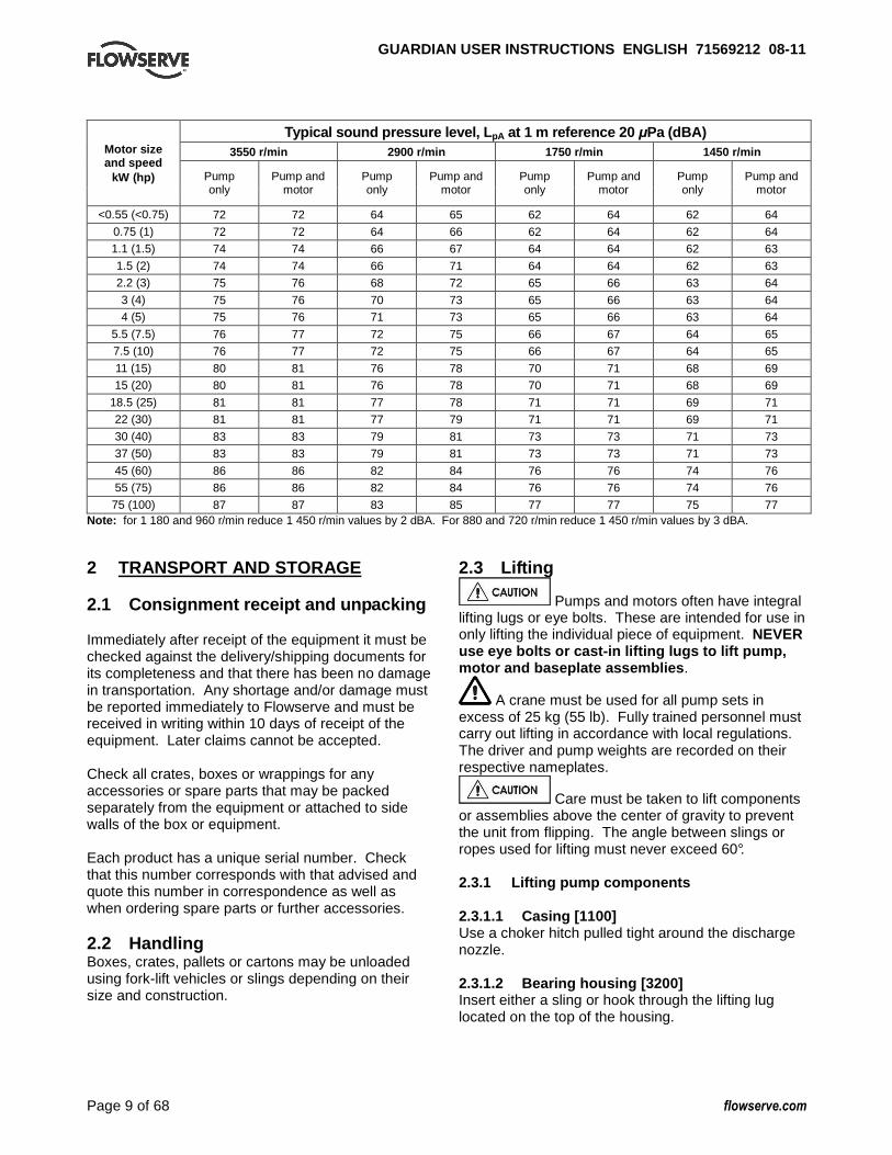
1.9 Noise level Attention must be given to the exposure of personnel to the noise, and local legislation will define when guidance to personnel on noise limitation is required, and when noise exposure reduction is mandatory. This is typically 80 to 85 dBA. The usual approach is to control the exposure time to the noise or to enclose the machine to reduce emitted sound. You may have already specified a limiting noise level when the equipment was ordered, however if no noise requirements were defined, then attention is drawn to the following table to give an indication of equipment noise level so that you can take the appropriate action in your plant. Pump noise level is dependent on a number of operational factors, flow rate, pipework design and acoustic characteristics of the building, and so the values given are subject to a 3 dBA tolerance and cannot be guaranteed. Similarly the motor noise assumed in the “pump and motor” noise is that typically expected from standard and high efficiency motors when on load directly driving the pump. Note that a motor driven by an inverter may show an increased noise at some speeds. If a pump unit only has been purchased for fitting with your own driver then the “pump only” noise levels in the table should be combined with the level for the driver obtained from the supplier. Consult Flowserve or a noise specialist if assistance is required in combining the values.
For units driven by equipment other than electric motors or units contained within enclosures, see the accompanying information sheets and manuals. It is recommended that where exposure approaches the prescribed limit, then site noise measurements should be made. The values are in sound pressure level LpA at 1 m (3.3 ft) from the machine, for “free field conditions over a reflecting plane”. For estimating sound power level LWA (re 1 pW) then add 14 dBA to the sound pressure value.
GUARDIAN USER INSTRUCTIONS ENGLISH 71569212 08-1 1
Page 9 of 68 flowserve.com
Typical sound pressure level, L pA at 1 m reference 20 µPa (dBA)
3550 r/min 2900 r/min 1750 r/min 1450 r/min Motor size and speed
kW (hp) Pump only
Pump and motor
Pump only
Pump and motor
Pump only
Pump and motor
Pump only
Pump and motor
<0.55 (<0.75) 72 72 64 65 62 64 62 64
0.75 (1) 72 72 64 66 62 64 62 64 1.1 (1.5) 74 74 66 67 64 64 62 63
1.5 (2) 74 74 66 71 64 64 62 63 2.2 (3) 75 76 68 72 65 66 63 64
3 (4) 75 76 70 73 65 66 63 64 4 (5) 75 76 71 73 65 66 63 64
5.5 (7.5) 76 77 72 75 66 67 64 65 7.5 (10) 76 77 72 75 66 67 64 65
11 (15) 80 81 76 78 70 71 68 69 15 (20) 80 81 76 78 70 71 68 69
18.5 (25) 81 81 77 78 71 71 69 71 22 (30) 81 81 77 79 71 71 69 71
30 (40) 83 83 79 81 73 73 71 73 37 (50) 83 83 79 81 73 73 71 73
45 (60) 86 86 82 84 76 76 74 76 55 (75) 86 86 82 84 76 76 74 76
75 (100) 87 87 83 85 77 77 75 77 Note: for 1 180 and 960 r/min reduce 1 450 r/min values by 2 dBA. For 880 and 720 r/min reduce 1 450 r/min values by 3 dBA. 2 TRANSPORT AND STORAGE 2.1 Consignment receipt and unpacking Immediately after receipt of the equipment it must be checked against the delivery/shipping documents for its completeness and that there has been no damage in transportation. Any shortage and/or damage must be reported immediately to Flowserve and must be received in writing within 10 days of receipt of the equipment. Later claims cannot be accepted. Check all crates, boxes or wrappings for any accessories or spare parts that may be packed separately from the equipment or attached to side walls of the box or equipment. Each product has a unique serial number. Check that this number corresponds with that advised and quote this number in correspondence as well as when ordering spare parts or further accessories. 2.2 Handling Boxes, crates, pallets or cartons may be unloaded using fork-lift vehicles or slings depending on their size and construction.
2.3 Lifting
Pumps and motors often have integral lifting lugs or eye bolts. These are intended for use in only lifting the individual piece of equipment. NEVER use eye bolts or cast-in lifting lugs to lift pump, motor and baseplate assemblies .
A crane must be used for all pump sets in excess of 25 kg (55 lb). Fully trained personnel must carry out lifting in accordance with local regulations. The driver and pump weights are recorded on their respective nameplates.
Care must be taken to lift components or assemblies above the center of gravity to prevent the unit from flipping. The angle between slings or ropes used for lifting must never exceed 60°. 2.3.1 Lifting pump components 2.3.1.1 Casing [1100] Use a choker hitch pulled tight around the discharge nozzle. 2.3.1.2 Bearing housing [3200] Insert either a sling or hook through the lifting lug located on the top of the housing.

GUARDIAN USER INSTRUCTIONS ENGLISH 71569212 08-1 1
Page 10 of 68 flowserve.com
2.3.1.3 Power end Same as bearing housing.
To avoid distortion, the pump unit should be lifted as shown. 2.3.1.4 Bare pump Sling around the pump discharge nozzle and around the outboard end of the bearing housing with separate slings. Choker hitches must be used at both attachment points and pulled tight. Make sure the completion of the choker hitch on the discharge nozzle is toward the coupling end of the pump shaft as shown in Figure 2-1. The sling lengths should be adjusted to balance the load before attaching the lifting hook.
Figure 2.1
2.3.1.5 Lifting pump, motor and baseplate
assembly If the baseplate has lifting holes cut in the sides at the end insert lifting S hooks at the four corners and use slings or chains to connect to the lifting eye as shown in Figure 2-2. Do not use slings through the lifting holes.
Figure 2.2
For other baseplates, sling around the pump discharge nozzle, and around the outboard end of the motor frame using choker hitches pulled tight. (Figure 2-1.)
Figure 2.3
The sling should be positioned so the weight is not carried through the motor fan housing. Make sure the completion of the choker hitch on the discharge nozzle is toward the coupling end of the pump shaft as shown in Figure 2-1. 2.4 Storage
Store the pump in a clean, dry location away from vibration. Leave flange covers in place to keep dirt and other foreign material out of pump casing. Turn the pump shaft at regular intervals to prevent brinelling of the bearings. The pump may be stored as above for up to 6 months. Consult Flowserve for preservative actions when a longer storage period is needed. 2.4.1 Short term storage Normal packaging is designed to protect the pump and parts during shipment and for dry, indoor storage for up to six months or less. The following is an overview of our normal packaging: • All loose unmounted items are packaged in a
water proof plastic bag and placed under the coupling guard. Larger items are boxed and metal banded to the baseplate. For pumps not mounted on a baseplate, the bag and/or box is placed inside the shipping container.
• Inner surfaces of the bearing housing, shaft (area through bearing housing) and bearings are coated with Cortec VCI-329 rust inhibitor, or equal.
Bearing housings are not filled with oil prior to shipment.)

GUARDIAN USER INSTRUCTIONS ENGLISH 71569212 08-1 1
Page 11 of 68 flowserve.com
• The internal surfaces of ferrous casings, covers, flange faces, and the impeller surface are sprayed with Cortec VCI-389, or equal.
• Exposed shafts are taped with Polywrap. • Flange covers are secured to both the suction
and discharge flanges. • Assemblies ordered with external piping, in some
cases components may be disassembled for shipment.
• The pump must be stored in a covered, dry location.
2.4.2 Long term storage Long term storage is defined as more than six months, but less than 12 months. The procedure Flowserve follows for long term storage of pumps is given below. These procedures are in addition to the short term procedure: • Each assembly is hermetically (heat) sealed from
the atmosphere by means of tack wrap sheeting and rubber bushings (mounting holes).
• Desiccant bags are placed inside the tack wrapped packaging.
• A solid wood box is used to cover the assembly. This packaging will provide protection for up to twelve months from humidity, salt laden air, dust etc. After unpacking, protection will be the responsibility of the user. Addition of oil to the bearing housing will remove the inhibitor. If units are to be idle for extended periods after addition of lubricants, inhibitor oils and greases should be used. Every three months, the pump shaft should be rotated approximately 10 revolutions. 2.5 Recycling and end of product life At the end of the service life of the product or its parts, the relevant materials and parts should be recycled or disposed of using an environmentally acceptable method and in accordance with local regulations. If the product contains substances that are harmful to the environment, these should be removed and disposed of in accordance with current local regulations. This also includes the liquids and/or gases that may be used in the "seal system" or other utilities.
Make sure that hazardous substances are disposed of safely and that the correct personal protective equipment is used. The safety specifications must be in accordance with the current local regulations at all times.
3 DESCRIPTION 3.1 Configurations The Durco G and H Series Magnetic Drive chemical process pump are end suction, single stage, centrifugal pumps. The horizontal family conforms to ASME B73.3M, which has a centerline discharge and is represented by our Standard long-coupled, Close-coupled (Group 1 only), and Unitized self-priming variants. 3.2 Nomenclature The pump size will be engraved on the nameplate typically as below:
BG 1.5 x 1 - 62/5.00 RV • “BG” refers to the magnetic coupling size – see
Table 3-2. • “1.5” refers to the suction diameter (1.5 in.) • “1” refers to the discharge diameter (1.0 in.) • “62” refers to nominal impeller diameter (6 & 2/8 in.) • “5.00” refers to actual impeller diameter (5.00 in) • “RV” refers to Reverse Vane impeller. (Open
impeller design not available on Guardian G & H series pumps.)
Pump design variation: A = This pump has been redesigned from an earlier
version. The impeller and casing are no longer interchangeable with the earlier version.
H = This pump is designed for a higher flow capacity than another pump with the same basic designation. (Examples: 4X3-10 and 4X3-10H; 6X4-10 and 6X4-10H).
An example of the nameplate used on the Guardian G & H Series pump is shown below. This nameplate, which is always mounted on the Guardian G & H Series bearing housing, is shown in Figure 3-1. Figure 3.1: Nameplate
Serial No. Equipment No.
Purchase
Serial No. Equipment No.
Purchase Order Model
Size MDP
Material Date DD/MMM/YY

GUARDIAN USER INSTRUCTIONS ENGLISH 71569212 08-1 1
Page 12 of 68 flowserve.com
3.3 Design of major parts 3.3.1 Pump casing and impeller Removal of the casing is not required when performing maintenance of the rotating element. The pump is designed with a gasket perpendicular to the shaft allowing the rotating element to be easily removed (back pull out). The impeller is reverse vane; there is no option for an open impeller. 3.3.2 Magnetic coupling See Figure 3-2 for magnetic coupling static torque values. Outer and inner magnets are separated by a containment shell which isolates the process fluid from the atmosphere. When the motor drives the outer magnet, the attraction between the outer and inner magnet causes the pump shaft and impeller to rotate. See Figure 3-3. This “magnetic coupling” is produced by alternating polarities between the magnet pairs on the inner and outer magnet assemblies. The alternating magnet polarity also causes repulsion between adjacent magnets and prevents the coupling from slipping or decoupling. (See Figure 3-4.) Figure 3-2: Magnetic coupling static torque values
Pump size
Pump prefix
Magnet length
Torque at 20 ºC (68 ºF) Nm (lbf ٠in.)
AG/AH 0.5 in. 12 (110) BG/BH 1.0 in. 33 (290) CG/CH 1.5 in. 57 (500) DG/DH 2.0 in. 75 (660)
Group 1
JG/JH 2.5 in. 92 (810) JG/JH 0.5 in. 23 (200) KG/KH 1.0 in. 57 (500) LG/LH 1.5 in. 99 (870) MG/MH 2.0 in. 138 (1220) NG/NH 2.5 in. 175 (1540) PG/PH 3.0 in. 220 (1940)
Group 2
QG/QH 3.5 in. 257 (2270) Figure 3-3: Magnetic drive schematic (shaded areas rotate)
Figure 3-4: Magnetic coupling
3.3.3 Inner rotating assembly The wetted, inner rotating assembly consisting of the inner magnet, pump shaft and impeller is supported radially by bushings. The bushings also carry radial and axial loading from the impeller. A small amount of process fluid circulates in the containment area to lubricate these bearings and cool the containment shell. 3.3.4 Lubrication and cooling path Referring to Figure 3-5, the process fluid enters the containment area through two lubrication holes in the bearing holder (A). The fluid is divided at this point with a small portion providing lubrication to the inboard bushing and thrust journal before returning to low pressure (B). The remaining portion moves across the outboard bushing (C) at which point it is divided with a portion lubricating the outboard thrust journal (D) and the remaining passing through holes in the inner magnet assembly (E). The process fluid cools the containment shell (F) before mixing with flow entering from two holes in the bearing holder (G). The mixed flow then returns to the process flow through the two return lubrication holes (H). Two of the holes in the bearing holder (G) are located at the six and twelve o’clock position to vent and drain the containment area during startup and shutdown. This circulation path ensures positive flow and lubrication to the bushings and thrust journals with the coolest fluid, i.e. before cooling the containment shell.

GUARDIAN USER INSTRUCTIONS ENGLISH 71569212 08-1 1
Page 13 of 68 flowserve.com
Figure 3-5: Lubrication and cooling path
3.3.5 Power end bearings and lubrication Ball bearings are fitted as standard on long-coupled pumps and may be either oil or grease lubricated. Close coupled pumps utilize the motor bearings for support of the outer magnet. 3.3.6 Bearing housing Large oil bath reservoir. (Long-coupled pumps only.) 3.3.7 Driver The driver is normally an electric motor. Different drive configurations may be fitted such as internal combustion engines, turbines, hydraulic motors etc driving via couplings, belts, gearboxes, drive shafts etc. 3.3.8 Accessories Accessories may be fitted when specified by the customer. 3.4 Performance and operation limits This product has been selected to meet the specification of your purchase order see section 1.5. The following data is included as additional information to help with your installation. It is typical, and factors such as liquid being pumped, temperature, and material of construction may influence this data. If required, a definitive statement for your application can be obtained from Flowserve. 3.4.1 General temperature limits See Figures 3-6 and 3-7 for general temperature limits for Guardian G & H series pumps. 3.4.2 Pressure-temperature ratings The pressure-temperature ratings for Guardian G & H series pumps are shown in Figures 3-9A and 3-9B. To determine which casing material group to reference, identify the appropriate casing “Material Group No.” in Figure 3-8. Interpolation may be used to find the pressure rating for a specific temperature.
The maximum discharge pressure must be less than or equal to the P-T rating. Discharge pressure may be approximated by adding the suction pressure and the differential head developed by the pump. The suction pressure limit for Guardian G & H series pumps is limited by the P-T rating. Example. The pressure temperature rating for a Guardian pump with Class 300 flanges and CF8M construction at an operating temperature of 149 ˚C is found as follows: a) From Figure 3-8, the correct material group for
CF8M is 2.2. b) From Figure 3-9B, the pressure-temperature
rating is 21.5 bar. 3.4.3 Alloy cross reference chart Figure 3-8 is the alloy cross-reference chart for all Guardian G & H series pumps. 3.4.4 Minimum continuous flow The minimum continuous flow (MCF) is based on a percentage of the best efficiency point (BEP). Figure 3-10 identifies the MCF for all G & H series Guardian pumps. 3.4.5 Minimum suction pipe submergence The minimum submergence for Unitized self-priming pumps is shown in Figure 3-11 and 3-12.
GUARDIAN USER INSTRUCTIONS ENGLISH 71569212 08-1 1
Page 14 of 68 flowserve.com
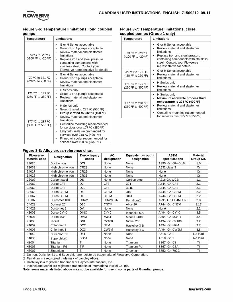
Figure 3-6: Temperature limitations, long coupled pumps
Temperature Limitations
-73 ºC to -29 ºC (-100 ºF to -20 ºF)
• G or H Series acceptable • Group 1 or 2 pumps acceptable • Review material and elastomer
limitations • Replace iron and steel pressure
containing components with stainless steel. Contact your Flowserve representative for details
-29 ºC to 121 ºC (-20 ºF to 250 ºF)
• G or H Series acceptable • Group 1 or 2 pumps acceptable • Review material and elastomer
limitations
121 ºC to 177 ºC (250 ºF to 350 ºF)
• H Series only • Group 1 or 2 pumps acceptable • Review material and elastomer
limitations
177 ºC to 287 ºC (350 ºF to 550 ºF)
• H Series only • Group 1 rated to 287 ºC (550 ºF) • Group 2 rated to 232 ºC (450 ºF)! • Review material and elastomer
limitations • Centerline mounting recommended
for services over 177 ºC (350 ºF) • Labyrinth seals recommended for
services over 218 ºC (425 ºF) • Finned oil cooler recommended for
services over 190 ºC (375 ºF)
Figure 3-7: Temperature limitations, close coupled pumps (Group 1 only)
Temperature Limitations
-73 ºC to -29 ºC (-100 ºF to -20 ºF)
• G or H Series acceptable • Review material and elastomer
limitations • Replace iron and steel pressure
containing components with stainless steel. Contact your Flowserve representative for details
-29 ºC to 121 ºC (-20 ºF to 250 ºF)
• G or H Series acceptable • Review material and elastomer
limitations
121 ºC to 177 ºC (250 ºF to 350 ºF)
• H Series only • Review material and elastomer
limitations
177 ºC to 204 ºC (350 ºF to 400 ºF)
• H Series only • Maximum allowable process fluid
temperature is 204 ºC (400 ºF) • Review material and elastomer
limitations • Centerline mounting recommended
for services over 177 ºC (350 ºF)
Figure 3-8: Alloy cross-reference chart
Flowserve material code
Designation Durco legacy codes
ACI designation
Equivalent wrought designation
ASTM specifications
Material Group No.
E3020 Ductile iron DCI None None A395, Gr. 60-40-18 1.0 E3033 High chrome iron CR28 None None A532 class 3 Cr E4027 High chrome iron CR29 None None None Cr E4028 High chrome iron CR35 None None None Cr C3009 Carbon steel DS None Carbon steel A216 Gr. WCB 1.1 C3062 Durco CF8 D2 CF8 304 A744, Gr. CF8 2.1 C3069 Durco CF3 D2L CF3 304L A744, Gr. CF3 2.1 C3063 Durco CF8M D4 CF8M 316 A744, Gr. CF8M 2.2 C3067 Durco CF3M D4L CF3M 316L A744, Gr. CF3M 2.2 C3107 Durcomet 100 CD4M CD4MCuN Ferralium A995, Gr. CD4MCuN 2.8 C4028 Durimet 20 D20 CN7M Alloy 20 A744, Gr. CN7M 3.17 C4029 Durcomet 5 DV None None None 2.2 K3005 Durco CY40 DINC CY40 Inconel 600 A494, Gr. CY40 3.5 K3007 Durco M35 DMM M351 Monel 400 A494, Gr. M35-1 3.4 K3008 Nickel DNI CZ100 Nickel 200 A494, Gr. CZ100 3.2 K4007 Chlorimet 2 DC2 N7M Hastelloy B A494, Gr. N7M 3.7 K4008 Chlorimet 3 DC3 CW6M Hastelloy C A494, Gr. CW6M 3.8 E3042 Durichlor 51 D51 None None A518, Gr. 2 No load E4035 Superchlor SD51 None None A518, Gr. 2 No load H3004 Titanium Ti None Titanium B367, Gr. C3 Ti H3005 Titanium-Pd TiP None Titanium-Pd B367, Gr. C8A Ti H3007 Zirconium Zr None Zirconium B752, Gr. 702C Ti
Duriron, Durichlor 51 and Superchlor are registered trademarks of Flowserve Corporation. Ferralium is a registered trademark of Langley Alloys. Hastelloy is a registered trademark of Haynes International, Inc. Inconel and Monel are registered trademarks of International Nickel Co. Inc. Note: some materials listed above may not be availa ble for use in some parts of Guardian pumps.

GUARDIAN USER INSTRUCTIONS ENGLISH 71569212 08-1 1
Page 15 of 68 flowserve.com
Figure 3-9A: All Guardian G & H series pumps with c lass 150 flanges Material Group No.
1.0 1.1 2.1 2.2 2.8 3.2 3.4 3.5 3.7 3.8 3.17 Ti Cr Temp
ºC ( ºF) bar (psi) -73
(-100) – – 19.0
(275) 19.0 (275)
19.7 (285)
9.7 (140)
15.9 (230)
15.2 (220)
20.0 (290)
20.0 (290)
15.9 (230)
20.0 (290)
–
-29 (-20)
17.2 (250)
19.7 (285)
19.0 (275)
19.0 (275)
19.7 (285)
9.7 (140)
15.9 (230)
15.2 (220)
20.0 (290)
20.0 (290)
15.9 (230)
20.0 (290)
–
-18 (0)
17.2 (250)
19.7 (285)
19.0 (275)
19.0 (275)
19.7 (285)
9.7 (140)
15.9 (230)
15.2 (220)
20.0 (290)
20.0 (290)
15.9 (230)
20.0 (290)
12.6 (183)
38 (100)
17.2 (250)
19.7 (285)
19.0 (275)
19.0 (275)
19.7 (285)
9.7 (140)
15.9 (230)
15.2 (220)
20.0 (290)
20.0 (290)
15.9 (230)
20.0 (290)
12.6 (183)
93 (200)
16.2 (235)
17.9 (260)
15.9 (230)
16.2 (235)
17.9 (260)
9.7 (140)
13.8 (200)
13.8 (200)
17.9 (260)
17.9 (260)
13.8 (200)
17.9 (260)
12.6 (183)
149 (300)
14.8 (215)
15.9 (230)
14.1 (205)
14.8 (215)
15.9 (230)
9.7 (140)
13.1 (190)
12.4 (180)
15.9 (230)
15.9 (230)
12.4 (180)
15.9 (230)
12.6 (183)
171 (340)
14.4 (209)
15.0 (218)
13.7 (199)
14.3 (207)
15.0 (218)
9.7 (140)
13.0 (188)
12.1 (176)
15.0 (218)
15.0 (218)
11.9 (172)
15.0 (218)
12.6 (183)
204 (400)
13.8 (200)
13.8 (200)
13.1 (190)
13.4 (195)
13.8 (200)
9.7 (140)
12.8 (185)
11.7 (170)
13.8 (200)
13.8 (200)
11.0 (160)
13.8 (200)
–
260 (500)
11.7 (170)
11.7 (170)
11.7 (170)
11.7 (170)
11.7 (170)
9.7 (140)
11.7 (170)
11.0 (160)
11.7 (170)
11.7 (170)
10.3 (150)
11.7 (170)
–
316 (600)
9.7 (140)
9.7 (140)
9.7 (140)
9.7 (140)
9.7 (140)
9.7 (140)
9.7 (140)
9.7 (140)
9.7 (140)
9.7 (140)
9.7 (140)
9.7 (140)
–
Figure 3-9B: All Guardian G & H series pumps with c lass 300 flanges
Material Group No. 1.0 1.1 2.1 2.2 2.8 3.2 3.4 3.5 3.7 3.8 3.17 Ti
Temp ºC
( ºF) bar (psi) -73
(-100) – –
24.1 (350)
24.1 (350)
24.1 (350)
17.4 (252)
24.1 (350)
24.1 (350)
24.1 (350)
24.1 (350)
24.1 (350)
24.1 (350)
-29 (-20)
24.1 (350)
24.1 (350)
24.1 (350)
24.1 (350)
24.1 (350)
17.4 (252)
24.1 (350)
24.1 (350)
24.1 (350)
24.1 (350)
24.1 (350)
24.1 (350)
-18 (0)
24.1 (350)
24.1 (350)
24.1 (350)
24.1 (350)
24.1 (350)
17.4 (252)
24.1 (350)
24.1 (350)
24.1 (350)
24.1 (350)
24.1 (350)
24.1 (350)
38 (100)
24.1 (350)
24.1 (350)
24.1 (350)
24.1 (350)
24.1 (350)
17.4 (252)
24.1 (350)
24.1 (350)
24.1 (350)
24.1 (350)
24.1 (350)
24.1 (350)
93 (200)
22.6 (328)
22.0 (319)
20.1 (292)
20.8 (301)
23.2 (336)
17.4 (252)
21.3 (309)
22.9 (332)
24.1 (350)
24.1 (350)
20.9 (303)
21.4 (310)
149 (300)
21.3 (309)
21.4 (310)
18.1 (263)
18.8 (272)
21.4 (310)
17.4 (252)
19.9 (289)
21.4 (310)
23.5 (341)
23.5 (341)
18.7 (271)
18.7 (271)
204 (400)
19.8 (287)
20.7 (300)
16.6 (241)
17.3 (250)
19.8 (287)
17.4 (252)
19.3 (280)
19.9 (288)
22.7 (329)
22.7 (329)
16.9 (245)
15.9 (231)
260 (500)
18.7 (271)
19.6 (284)
15.3 (222)
16.1 (233)
18.5 (268)
17.4 (252)
19.1 (277)
19.3 (280)
21.4 (310)
21.4 (310)
15.7 (228)
13.2 (191)
316 (600)
17.5 (254)
17.9 (260)
14.6 (211)
15.1 (219)
17.9 (259)
17.4 (252)
19.1 (277)
19.2 (278)
19.5 (282)
19.5 (282)
14.5 (210)
10.5 (152)
Note: temperature limitations in these charts take into account material choice only. Actual temperature limitations of the Guardian pump may be different depending on pump size, model, or elastomers used. Refer to Section 3.4.1 for specific temperature limitations of Guardian pumps independent of material choice.

GUARDIAN USER INSTRUCTIONS ENGLISH 71569212 08-1 1
Page 16 of 68 flowserve.com
Figure 3-10: Minimum continuous flow MCF % of BEP
Pump size 3 500/2 900 r/min
1 750/1 450 r/min
1 180/960 r/min
1K3x2-6 20 % 10 % 10 % 2K3x2-8 20 % 10 % 10 % 2K4x3-8 20 % 10 % 10 % 2K3x2-10 30 % 10 % 10 % 2K4x3-10 30 % 10 % 10 % 2K6x4-10 40 % 10 % 10 % 2K6x4-10H n.a. 20 % 10 % 2K3x1.5-13 30 % 10 % 10 % 2K3x2-13 40 % 10 % 10 % 2K4x3-13 40 % 20 % 10 % 2K6x4-13 60 % 40 % 10 % All other sizes 10 % 10 % 10 %
Figure 3-11: Minimum submergence
Figure 3-12: Minimum submergence
3.4.6 Viscosity limitations The allowable viscosity range for Guardian G & H series pumps is 0.25 cP to 300 cP. Please consult your Flowserve representative for services with viscosities less than 0.25 cP. 3.4.7 Entrained solids For process fluids with entrained solids the following restrictions apply to the solids particles: • 300 micron (0.012 in.) maximum diameter • Less than 3.0 % solids by weight • 2 Moh hardness or less (roughly equivalent to
gypsum) • No ferrous particles
4 INSTALLATION 4.1 Location The pump should be located to allow room for access, ventilation, maintenance, and inspection with ample headroom for lifting and should be as close as practicable to the supply of liquid to be pumped. Refer to the general arrangement drawing for the pump set. 4.2 Part assemblies The supply of motors and baseplates are optional. As a result, it is the responsibility of the installer to ensure that the motor is assembled to the pump and aligned as detailed in section 4.5 and 4.8. 4.3 Foundation Protection of openings and threads When the pump is shipped, all threads and all openings are covered. This protection/covering should not be removed until installation. If, for any reason, the pump is removed from service, this protection should be reinstalled. 4.3.1 Rigid baseplates - overview The function of a baseplate is to provide a rigid foundation under a pump and its driver that maintains alignment between the two. Baseplates may be generally classified into two types: • Foundation-mounted, grouted design (Figure 4-1) • Stilt mounted, or free-standing (Figure 4-2) Figure 4-1: Foundation mounted baseplate
Figure 4-2: Stilt mounted baseplate
GUARDIAN USER INSTRUCTIONS ENGLISH 71569212 08-1 1
Page 17 of 68 flowserve.com
Baseplates intended for grouted installation are designed to use the grout as a stiffening member. Stilt mounted baseplates, on the other hand, are designed to provide their own rigidity. Therefore, the designs of the two baseplates are usually different. Regardless of the type of baseplate used, it must provide certain functions that ensure a reliable installation. Three of these requirements are: • The baseplate must provide sufficient rigidity to
assure the assembly can be transported and installed, given reasonable care in handling, without damage. It must also be rigid enough when properly installed to resist operating loads.
• The baseplate must provide a reasonably flat mounting surface for the pump and driver. Uneven surfaces will result in a soft-foot condition that may make alignment difficult or impossible. Flowserve’s experience indicates that a baseplate that has a top surface flatness of 1.25 mm/m (0.015 in./ft) across the diagonal corners of the baseplate provides such a mounting surface. Therefore, this is the tolerance to which we supply our standard baseplate. Some users may desire an even flatter surface, which can facilitate installation and alignment. Flowserve will supply flatter baseplates upon request at extra cost. For example, mounting surface flatness of 0.17 mm/m (0.002 in./ft) is offered on the Flowserve Type E “Ten Point” baseplate shown in Figure 4-1.
• The baseplate must be designed to allow the user to final field align the pump and driver to within their own particular standards and to compensate for any pump or driver movement that occurred during handling. Normal industry practice is to achieve final alignment by moving the motor to match the pump. Flowserve’s practice is to confirm in our shop that the pump assembly can be accurately aligned. Before shipment, the factory verifies that there is enough horizontal movement capability at the motor to obtain a “perfect” final alignment when the installer puts the baseplate assembly into its original, top leveled, unstressed condition.
4.3.2 Stilt and spring mounted baseplates Flowserve offers stilt and spring mounted baseplates. (See Figure 4-2 for stilt mounted option.) The low vibration levels of Guardian G & H series pumps allow the use of these baseplates - provided they are of a rigid design. The baseplate is set on a flat surface with no tie down bolts or other means of anchoring it to the floor. General instructions for assembling these baseplates are given below. For dimensional information, please refer to the appropriate Flowserve “Sales Print.”
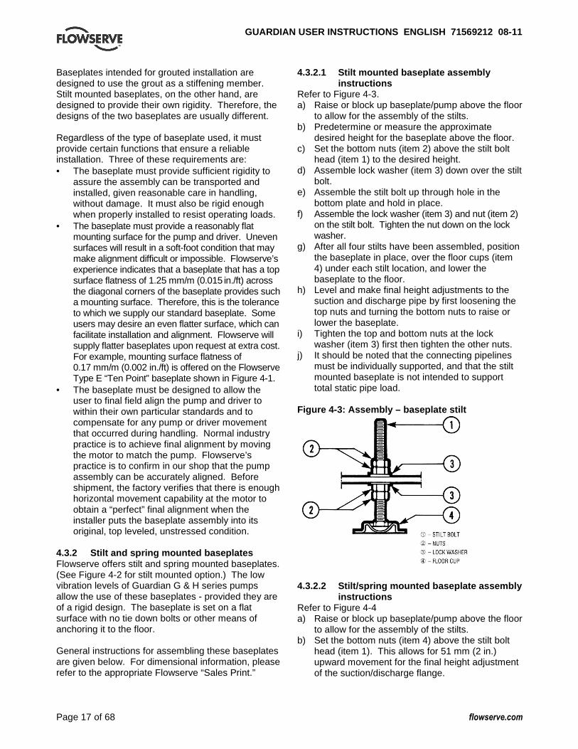
4.3.2.1 Stilt mounted baseplate assembly instructions
Refer to Figure 4-3. a) Raise or block up baseplate/pump above the floor
to allow for the assembly of the stilts. b) Predetermine or measure the approximate
desired height for the baseplate above the floor. c) Set the bottom nuts (item 2) above the stilt bolt
head (item 1) to the desired height. d) Assemble lock washer (item 3) down over the stilt
bolt. e) Assemble the stilt bolt up through hole in the
bottom plate and hold in place. f) Assemble the lock washer (item 3) and nut (item 2)
on the stilt bolt. Tighten the nut down on the lock washer.
g) After all four stilts have been assembled, position the baseplate in place, over the floor cups (item 4) under each stilt location, and lower the baseplate to the floor.
h) Level and make final height adjustments to the suction and discharge pipe by first loosening the top nuts and turning the bottom nuts to raise or lower the baseplate.
i) Tighten the top and bottom nuts at the lock washer (item 3) first then tighten the other nuts.
j) It should be noted that the connecting pipelines must be individually supported, and that the stilt mounted baseplate is not intended to support total static pipe load.
Figure 4-3: Assembly – baseplate stilt
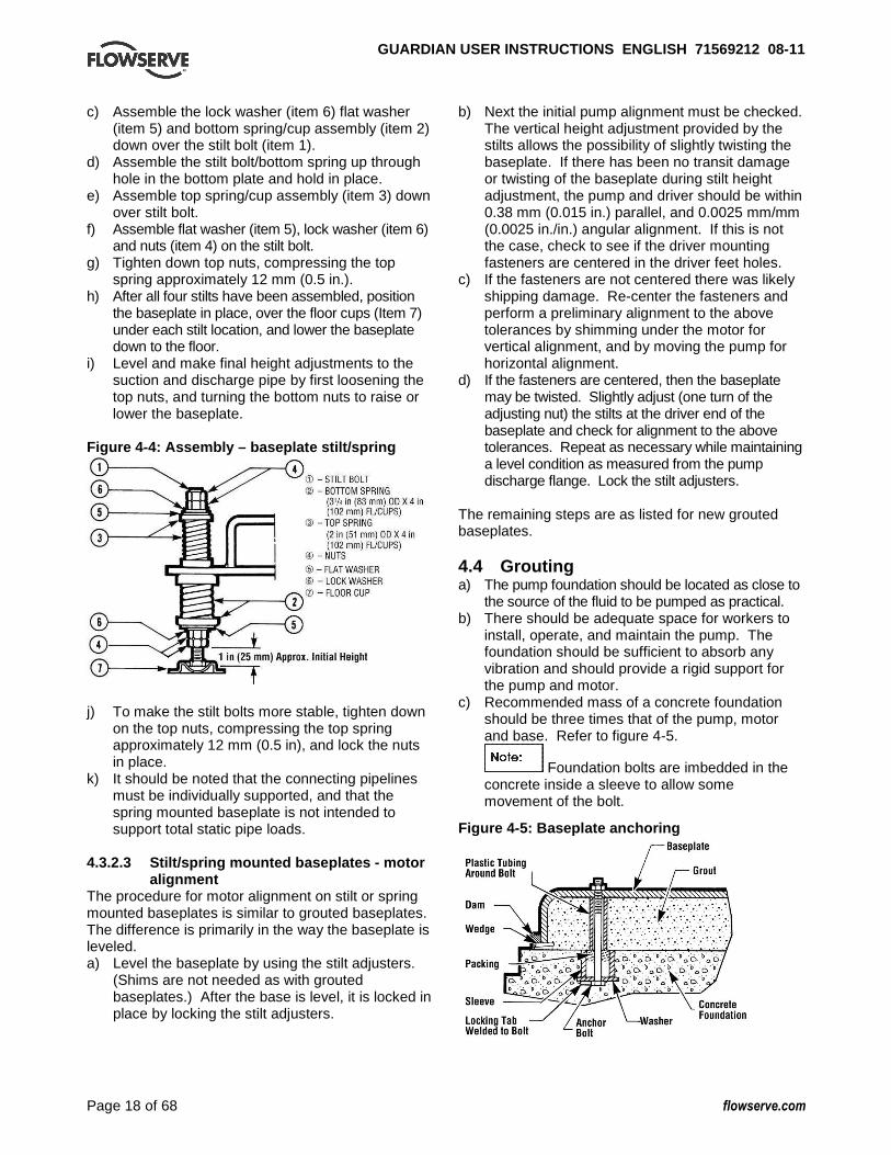
4.3.2.2 Stilt/spring mounted baseplate assembly
instructions Refer to Figure 4-4 a) Raise or block up baseplate/pump above the floor
to allow for the assembly of the stilts. b) Set the bottom nuts (item 4) above the stilt bolt
head (item 1). This allows for 51 mm (2 in.) upward movement for the final height adjustment of the suction/discharge flange.
GUARDIAN USER INSTRUCTIONS ENGLISH 71569212 08-1 1
Page 18 of 68 flowserve.com
c) Assemble the lock washer (item 6) flat washer (item 5) and bottom spring/cup assembly (item 2) down over the stilt bolt (item 1).
d) Assemble the stilt bolt/bottom spring up through hole in the bottom plate and hold in place.
e) Assemble top spring/cup assembly (item 3) down over stilt bolt.
f) Assemble flat washer (item 5), lock washer (item 6) and nuts (item 4) on the stilt bolt.
g) Tighten down top nuts, compressing the top spring approximately 12 mm (0.5 in.).
h) After all four stilts have been assembled, position the baseplate in place, over the floor cups (Item 7) under each stilt location, and lower the baseplate down to the floor.
i) Level and make final height adjustments to the suction and discharge pipe by first loosening the top nuts, and turning the bottom nuts to raise or lower the baseplate.
Figure 4-4: Assembly – baseplate stilt/spring
j) To make the stilt bolts more stable, tighten down
on the top nuts, compressing the top spring approximately 12 mm (0.5 in), and lock the nuts in place.
k) It should be noted that the connecting pipelines must be individually supported, and that the spring mounted baseplate is not intended to support total static pipe loads.
4.3.2.3 Stilt/spring mounted baseplates - motor
alignment The procedure for motor alignment on stilt or spring mounted baseplates is similar to grouted baseplates. The difference is primarily in the way the baseplate is leveled. a) Level the baseplate by using the stilt adjusters.
(Shims are not needed as with grouted baseplates.) After the base is level, it is locked in place by locking the stilt adjusters.
b) Next the initial pump alignment must be checked. The vertical height adjustment provided by the stilts allows the possibility of slightly twisting the baseplate. If there has been no transit damage or twisting of the baseplate during stilt height adjustment, the pump and driver should be within 0.38 mm (0.015 in.) parallel, and 0.0025 mm/mm (0.0025 in./in.) angular alignment. If this is not the case, check to see if the driver mounting fasteners are centered in the driver feet holes.
c) If the fasteners are not centered there was likely shipping damage. Re-center the fasteners and perform a preliminary alignment to the above tolerances by shimming under the motor for vertical alignment, and by moving the pump for horizontal alignment.
d) If the fasteners are centered, then the baseplate may be twisted. Slightly adjust (one turn of the adjusting nut) the stilts at the driver end of the baseplate and check for alignment to the above tolerances. Repeat as necessary while maintaining a level condition as measured from the pump discharge flange. Lock the stilt adjusters.
The remaining steps are as listed for new grouted baseplates. 4.4 Grouting a) The pump foundation should be located as close to
the source of the fluid to be pumped as practical. b) There should be adequate space for workers to
install, operate, and maintain the pump. The foundation should be sufficient to absorb any vibration and should provide a rigid support for the pump and motor.
c) Recommended mass of a concrete foundation should be three times that of the pump, motor and base. Refer to figure 4-5.
Foundation bolts are imbedded in the concrete inside a sleeve to allow some movement of the bolt.
Figure 4-5: Baseplate anchoring
GUARDIAN USER INSTRUCTIONS ENGLISH 71569212 08-1 1
Page 19 of 68 flowserve.com
d) Level the pump baseplate assembly. If the baseplate has machined coplanar mounting surfaces, these machined surfaces are to be referenced when leveling the baseplate. This may require that the pump and motor be removed from the baseplate in order to reference the machined faces. If the baseplate is without machined coplanar mounting surfaces, the pump and motor are to be left on the baseplate. The proper surfaces to reference when leveling the pump baseplate assembly are the pump suction and discharge flanges. DO NOT stress the baseplate.
e) Do not bolt the suction or discharge flanges of the pump to the piping until the baseplate foundation is completely installed. If equipped, use leveling jackscrews to level the baseplate. If jackscrews are not provided, shims and wedges should be used. (See Figure 4-5.) Check for levelness in both the longitudinal and lateral directions. Shims should be placed at all base anchor bolt locations, and in the middle edge of the base if the base is more than 1.5 m (5 ft.) long. Do not rely on the bottom of the baseplate to be flat. Standard baseplate bottoms are not machined, and it is not likely that the field mounting surface is flat.
f) After leveling the baseplate, tighten the anchor bolts. If shims were used, make sure that the baseplate was shimmed near each anchor bolt before tightening. Failure to do this may result in a twist of the baseplate, which could make it impossible to obtain final alignment.
g) Check the level of the baseplate to make sure that tightening the anchor bolts did not disturb the level of the baseplate. If the anchor bolts did change the level, adjust the jackscrews or shims as needed to level the baseplate.
h) Continue adjusting the jackscrews or shims and tightening the anchor bolts until the baseplate is level.
i) Check initial alignment. If the pump and motor were removed from the baseplate proceed with step j) first, then the pump and motor should be reinstalled onto the baseplate using Flowserve’s factory preliminary alignment procedure as described in section 4.5, and then continue with the following. As described above, pumps are given a preliminary alignment at the factory. This preliminary alignment is done in a way that ensures that, if the installer duplicates the factory conditions, there will be sufficient clearance between the motor hold down bolts and motor foot holes to move the motor into final alignment. If the pump and motor were properly reinstalled to the baseplate or if they were not removed from the baseplate and there has been no transit damage, and also if the above steps where done properly,
the pump and driver should be within 0.38 mm (0.015 in.) FIM (Full Indicator Movement) parallel, and 0.0025 mm/mm (0.0025 in./in.) FIM angular. If this is not the case, first check to see if the driver mounting fasteners are centered in the driver feet holes. If not, re-center the fasteners and perform a preliminary alignment to the above tolerances by shimming under the motor for vertical alignment, and by moving the pump for horizontal alignment.
j) Grout the baseplate. A non-shrinking grout should be used. Make sure that the grout fills the area under the baseplate. After the grout has cured, check for voids and repair them. Jackscrews, shims and wedges should be removed from under the baseplate at this time. If they were to be left in place, they could rust, swell, and cause distortion in the baseplate.
k) Run piping to the suction and discharge of the pump. There should be no piping loads transmitted to the pump after connection is made. Recheck the alignment to verify that there are no significant loads.
4.5 Initial alignment 4.5.1 Horizontal initial alignment procedure The purpose of factory alignment is to ensure that the user will have full utilization of the clearance in the motor holes for final job-site alignment. To achieve this, the factory alignment procedure specifies that the pump be aligned in the horizontal plane to the motor, with the motor foot bolts centered in the motor holes. This procedure ensures that there is sufficient clearance in the motor holes for the customer to field align the motor to the pump, to zero tolerance. This philosophy requires that the customer be able to place the base in the same condition as the factory. Thus the factory alignment will be done with the base sitting in an unrestrained condition on a flat and level surface. This standard also emphasizes the need to ensure the shaft spacing is adequate to accept the specified coupling spacer. The factory alignment procedure is summarized below: a) The baseplate is placed on a flat and level
workbench in a free and unstressed position. b) The baseplate is leveled as necessary. Leveling
is accomplished by placing shims under the rails of the base at the appropriate anchor bolt hole locations. Levelness is checked in both the longitudinal and lateral directions.
c) The motor and appropriate motor mounting hardware is placed on the baseplate and the motor is checked for any planar soft-foot condition. If any is present it is eliminated by shimming

GUARDIAN USER INSTRUCTIONS ENGLISH 71569212 08-1 1
Page 20 of 68 flowserve.com
d) The motor feet holes are centered on the motor mounting fasteners. This is done by using a centering nut as shown in Figure 4-6.
Figure 4-6: Motor centering fastener
e) The motor is fastened in place by tightening the nuts on two diagonal motor mounting studs.
f) The pump is put onto the baseplate and leveled. The foot piece under the bearing housing is adjustable. It is used to level the pump, if necessary. If an adjustment is necessary, add or remove shims [3126.1] between the foot piece and the bearing housing.
g) The spacer coupling gap is verified. h) The parallel and angular vertical alignment is
made by shimming under the motor. i) The motor feet holes are again centered on the
motor mounting studs using the centering nut. At this point the centering nut is removed and replaced with a standard nut. This gives maximum potential mobility for the motor to be horizontally moved during final, field alignment. All four motor feet are tightened down.
j) The pump and motor shafts are then aligned horizontally, both parallel and angular, by moving the pump to the fixed motor. The pump feet are tightened down.
k) Both horizontal and vertical alignment is again final checked as is the coupling spacer gap.
See section 4.8 for Final Shaft Alignment 4.6 Piping
The protective covers are fitted to both the suction and discharge flanges of the casing and must be removed prior to connecting the pump to any pipes. 4.6.1 4.6.1 Suction and discharge piping All piping must be independently supported, accurately aligned and preferably connected to the pump by a short length of flexible piping. The pump should not have to support the weight of the pipe or compensate for misalignment. It should be possible to install suction and discharge bolts through mating flanges without pulling or prying either of the flanges.
All piping must be tight. Pumps may air-bind if air is allowed to leak into the piping. If the pump flange(s) have tapped holes, select flange fasteners with thread engagement at least equal to the fastener diameter but that do not bottom out in the tapped holes before the joint is tight. 4.6.2 Suction piping To avoid NPSH and suction problems, suction piping must be at least as large as the pump suction connection. Never use pipe or fittings on the suction that are smaller in diameter than the pump suction size. Figure 4-7 illustrates the ideal piping configuration with a minimum of 10 pipe diameters between the source and the pump suction. In most cases, horizontal reducers should be eccentric and mounted with the flat side up as shown in Figure 4-8 with a maximum of one pipe size reduction. Never mount eccentric reducers with the flat side down. Horizontally mounted concentric reducers should not be used if there is any possibility of entrained air in the process fluid. Vertically mounted concentric reducers are acceptable. In applications where the fluid is completely deaerated and free of any vapor or suspended solids, concentric reducers are preferable to eccentric reducers
Figures 4-7 and Figure 4-8
Avoid the use of throttling valves and strainers in the suction line. Start up strainers must be removed shortly before start up. When the pump is installed below the source of supply, a valve should be installed in the suction line to isolate the pump and permit pump inspection and maintenance. However, never place a valve directly on the suction nozzle of the pump. Refer to the Durco Pump Engineering Manual and the Centrifugal Pump IOM Section of the Hydraulic Institute Standards for additional recommendations on suction piping. (See section 10.)

GUARDIAN USER INSTRUCTIONS ENGLISH 71569212 08-1 1
Page 21 of 68 flowserve.com
Refer to section 3.4 for performance and operating limits. 4.6.2.1 Guardian self-priming pumps The suction piping must be as short as possible and be as close to the diameter of the suction nozzle as is practical. The pump works by removing the air contained in the suction piping. Once removed, it operates exactly the same as a flooded suction standard pump. Longer and larger suction pipes have a greater volume of air that has to be removed, resulting in longer priming time. The suction piping and seal chamber must be airtight to allow priming to occur. When possible, it is recommended that suction piping be sloped slightly towards the casing to ensure no fluid is lost down the suction line during priming. 4.6.3 Discharge piping Install a valve in the discharge line. This valve is required for regulating flow and/or to isolate the pump for inspection and maintenance.
When fluid velocity in the pipe is high, for example, 3 m/s (10 ft/s) or higher, a rapidly closing discharge valve can cause a damaging pressure surge. A dampening arrangement should be provided in the piping. 4.6.3.1 Guardian self-priming pumps During the priming cycle, air from the suction piping is evacuated into the discharge piping. There must be a way for this air to vent. If air is not able to freely vent out the discharge pipe, it is typically recommended to install an air bleed line. The air bleed line is typically connected from the discharge pipe to the sump. Care must be taken to prevent air from re-entering suction pipe. 4.6.4 Allowable nozzle loads Flowserve chemical process pumps meet or exceed the allowable nozzle loads given by ANSI/HI 9.6.2. The following paragraphs describe how to calculate the allowable loads for each pump type and how to determine if the applied loads are acceptable. The configuration covered is for ASME B73.3 pumps, including the Guardian G & H series. 4.6.4.1 Guardian G & H series pumps (ASME
B73.3) The following steps are based upon ANSI/HI 9.6.2. All information necessary to complete the evaluation is given below. For complete details please review the standard. a) Determine the appropriate casing “Material Group
No.” from figure 3-8.
b) Find the “Casing material correction factor” in Figure 4-9 based upon the “Material Group No.” and operating temperature. Interpolation may be used to determine the correction factor for a specific temperature.
c) Find the “Baseplate correction factor” in Figure 4-10. The correction factor depends upon how the baseplate is to be installed.
d) Locate the pump model being evaluated in Figure 4-14 and multiply each load rating by the casing correction factor. Record the “adjusted Figure 4-14 loads”.
e) Locate the pump model being evaluated in Figures 4-15 and 4-16 and multiply each load rating by the baseplate correction factor. Record the adjusted Figure 4-15 and 4-16 loads.
f) Compare the “adjusted Figure 4-14 loads” to the values shown in figure 4-13. The lower of these two values should be used as the adjusted figure 4-13 values. (The HI standard also asks that figure 4-13 loads be reduced if figure 4-15 or 4-16 values are lower. Flowserve does not follow this step.)
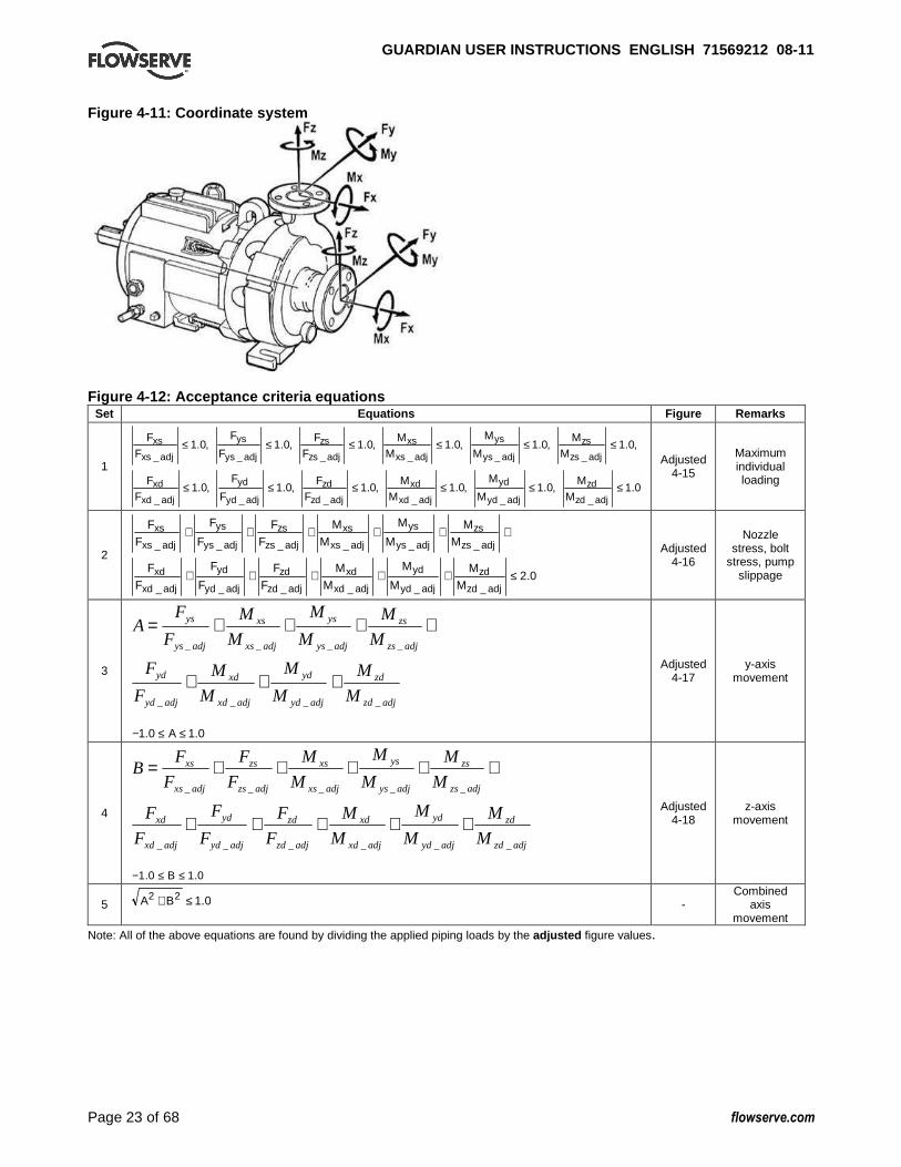
g) Calculate the applied loads at the casing flanges according to the coordinate system found in figure 4-11. The 12 forces and moments possible are Fxs, Fys, Fzs, Mxs, Mys, Mzs, Fxd, Fyd, Fzd, Mxd, Myd and Mzd. For example, Fxd designates Force in the “x” direction on the discharge flange. Mys designates the Moment about the “y”-axis on the suction flange.
h) Figure 4-12 gives the acceptance criteria equations. For long coupled pumps, equation sets 1 through 5 must be satisfied. For close coupled pumps, only equation sets 1 and 2 must be satisfied.
i) Equation set 1. Each applied load is divided by the corresponding adjusted figure 4-13 value. The absolute value of each ratio must be less than or equal to one.
j) Equation set 2. The summation of the absolute values of each ratio must be less than or equal to two. The ratios are the applied load divided by the adjusted figure 4-14 values.
k) Equation sets 3 and 4. These equations are checking for coupling misalignment due to nozzle loading in each axis. Each applied load is divided by the corresponding adjusted load from figure 4-15 and 4-16. The result of each equation must be between one and negative one.
l) Equation set 5. This equation calculates the total shaft movement from the results of equations 3 and 4. The result must be less than or equal to one.

GUARDIAN USER INSTRUCTIONS ENGLISH 71569212 08-1 1
Page 22 of 68 flowserve.com
Figure 4-9: Casing material correction factors Material Group No.
1.0 1.1 2.1 2.2 2.4 2.8 3.2 3.4 3.5 3.7 3.8 3.17 Ti Cr
Austenitic steels Nickel and nickel alloys Temp ˚C
Temp ˚F
DCI Carbon Steel
Type 304 and 304L
Type 316 and 316L
Type 321
CD-4MCu
Nickel Monel Inconel Hast B
Hast C
Alloy 20
Ti, Ti-Pd, Zr
High Chrome -18 to 171 ˚C (0 to
340 ˚F) -129 -200 - - 1.00 1.00 1.00 - 0.50 - - - - 0.83 - - -73 -100 - - 1.00 1.00 1.00 1.00 0.50 0.83 0.93 1.00 1.00 0.83 0.89 - -29 -20 0.89 1.00 1.00 1.00 1.00 1.00 0.50 0.83 0.93 1.00 1.00 0.83 0.89 0.65 38 100 0.89 1.00 1.00 1.00 1.00 1.00 0.50 0.83 0.93 1.00 1.00 0.83 0.89 0.65 93 200 0.83 0.94 0.83 0.86 0.93 1.00 0.50 0.74 0.88 1.00 1.00 0.72 0.86 0.65 150 300 0.78 0.91 0.75 0.78 0.83 0.92 0.50 0.69 0.82 1.01 1.01 0.65 0.81 0.65 205 400 0.73 0.88 0.69 0.72 0.69 0.85 0.50 0.67 0.77 0.98 0.98 0.58 0.69 0.65 260 500 0.69 0.83 0.63 0.67 0.64 0.80 0.50 0.66 0.74 0.92 0.92 0.54 0.57 - 315 600 0.65 0.76 0.60 0.63 0.60 0.77 0.50 0.66 0.74 0.84 0.84 0.50 0.45 -
Note: see specific temperature limitations of Guardian pumps in Sections 3-6 and 3-7. Figure 4-10: Baseplate correction factors
Base type Grouted Bolted Stilt mounted
Type A 1.0 0.7 0.65
Type B - Polybase 1.0 NA 0.95
Type C N/A 1.0 1.0
Type D 1.0 0.8 0.75
Type E - PIP 1.0 0.95 N/A
Polyshield - baseplate /foundation
1.0 N/A N/A
GUARDIAN USER INSTRUCTIONS ENGLISH 71569212 08-1 1
Page 23 of 68 flowserve.com
Figure 4-11: Coordinate system
Figure 4-12: Acceptance criteria equations Set Equations Figure Remarks
1
0.1,0.1,0.1,0.1,0.1,0.1
,0.1,0.1,0.1,0.1,0.1,0.1
______
______
≤≤≤≤≤≤
≤≤≤≤≤≤
adjzd
zd
adjyd
yd
adjxd
xd
adjzd
zd
adjyd
yd
adjxd
xd
adjzs
zs
adjys
ys
adjxs
xs
adjzs
zs
adjys
ys
adjxs
xs
MM
M
M
MM
FF
F
F
FF
MM
M
M
MM
FF
F
F
FF
Adjusted 4-15
Maximum individual loading
2
0.2______
______
≤+++++
++++++
adjzd
zd
adjyd
yd
adjxd
xd
adjzd
zd
adjyd
yd
adjxd
xd
adjzs
zs
adjys
ys
adjxs
xs
adjzs
zs
adjys
ys
adjxs
xs
M
M
M
M
M
M
F
F
F
F
F
F
M
M
M
M
M
M
F
F
F
F
F
F
Adjusted 4-16
Nozzle stress, bolt
stress, pump slippage
3
adjzd
zd
adjyd
yd
adjxd
xd
adjyd
yd
adjzs
zs
adjys
ys
adjxs
xs
adjys
ys
M
M
M
M
M
M
F
F
M
M
M
M
M
M
F
FA
____
____
+++
++++=
0.10.1 ≤≤− A
Adjusted 4-17
y-axis movement
4
adjzd
zd
adjyd
yd
adjxd
xd
adjzd
zd
adjyd
yd
adjxd
xd
adjzs
zs
adjys
ys
adjxs
xs
adjzs
zs
adjxs
xs
M
M
M
M
M
M
F
F
F
F
F
F
M
M
M
M
M
M
F
F
F
FB
______
_____
+++++
+++++=
0.10.1 ≤≤− B
Adjusted 4-18
z-axis movement
5 0.122 ≤+ BA - Combined
axis movement
Note: All of the above equations are found by dividing the applied piping loads by the adjusted figure values.
GUARDIAN USER INSTRUCTIONS ENGLISH 71569212 08-1 1
Page 24 of 68 flowserve.com
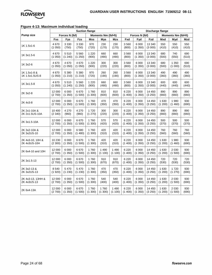
Figure 4-13: Maximum individual loading Suction flange Discharge flange
Forces N (lbf) Moments Nm (lbf•ft) Forces N (lbf) M oments Nm (lbf•ft) Pump size
Fxs Fys Fzs Mxs Mys Mzs Fxd Fyd Fzd Mxd Myd Mzd
1K 1.5x1-6 4 670 (1 050)
3 330 (750)
3 330 (750)
970 (720)
230 (170)
230 (170)
3 560 (800)
6 000 (1 350)
13 340 (3 000)
550 (410)
550 (410)
550 (410)
1K 3x1.5-6 4 670 (1 050)
5 510 (1 240)
5 560 (1 250)
1 220 (900)
660 (490)
660 (490)
3 560 (800)
6 000 (1 350)
13 340 (3 000)
680 (500)
740 (550)
690 (510)
1K 3x2-6 4 670 (1 050)
4 670 (1 050)
4 670 (1 050)
1 220 (900)
300 (220)
300 (220)
3 560 (800)
6 000 (1 350)
13 340 (3 000)
680 (500)
1 350 (1 000)
690 (510)
1K 1.5x1-8 & 1K 1.5x1.5US-8
4 670 (1 050)
5 380 (1 210)
5 380 (1 210)
970 (720)
260 (190)
260 (190)
3 560 (800)
6 000 (1 350)
13 340 (3 000)
490 (360)
490 (360)
490 (360)
1K 3x1.5-8 4 670 (1 050)
5 510 (1 240)
5 560 (1 250)
1 220 (900)
660 (490)
660 (490)
3 560 (800)
6 000 (1 350)
13 340 (3 000)
600 (440)
600 (440)
600 (440)
2K 3x2-8 12 000 (2 700)
6 000 (1 350)
6 670 (1 500)
1 760 (1 300)
810 (600)
810 (600)
6 220 (1 400)
6 000 (1 350)
14 450 (3 250)
890 (660)
890 (660)
890 (660)
2K 4x3-8 12 000 (2 700)
6 000 (1 350)
6 670 (1 500)
1 760 (1 300)
470 (350)
470 (350)
6 220 (1 400)
6 000 (1 350)
14 450 (3 250)
1 630 (1 200)
1 980 (1 460)
930 (690)
2K 2x1-10A & 2K 2x1.5US-10A
10 400 (2 340)
4 270 (960)
4 270 (960)
1 720 (1 270)
300 (220)
300 (220)
6 220 (1 400)
6 000 (1 350)
14 450 (3 250)
890 (660)
890 (660)
890 (660)
2K 3x1.5-10A 12 000 (2 700)
6 000 (1 350)
6 670 (1 500)
1 760 (1 300)
570 (420)
570 (420)
6 220 (1 400)
6 000 (1 350)
14 450 (3 250)
500 (370)
500 (370)
500 (370)
2K 3x2-10A & 2K 3x2US-10
12 000 (2 700)
6 000 (1 350)
6 580 (1 480)
1 760 (1 300)
420 (310)
420 (310)
6 220 (1 400)
6 000 (1 350)
14 450 (3 250)
760 (560)
760 (560)
760 (560)
2K 4x3-10, 10H & 2K 4x3US-10H
10 230 (2 300)
6 000 (1 350)
6 670 (1 500)
1 760 (1 300)
420 (310)
420 (310)
6 220 (1 400)
6 000 (1 350)
14 450 (3 250)
1 630 (1 200)
1 980 (1 460)
930 (690)
2K 6x4-10 and 10H 12 000 (2 700)
6 000 (1 350)
6 670 (1 500)
1 760 (1 300)
1 490 (1 100)
1 490 (1 100)
6 220 (1 400)
6 000 (1 350)
14 450 (3 250)
1 630 (1 200)
2 030 (1 500)
930 (690)
2K 3x1.5-13 12 000 (2 700)
6 000 (1 350)
6 670 (1 500)
1 760 (1 300)
910 (670)
910 (670)
6 220 (1 400)
6 000 (1 350)
14 450 (3 250)
720 (530)
720 (530)
720 (530)
2K 3x2-13 & 2K 3x2US-13
8 540 (1 920)
5 470 (1 230)
5 470 (1 230)
1 760 (1 300)
470 (350)
470 (350)
6 220 (1 400)
6 000 (1 350)
14 450 (3 250)
1 630 (1 200)
1 720 (1 270)
930 (690)
2K 4x3-13, 13HH & 2K 4x3US-13
12 000 (2 700)
6 000 (1 350)
6 670 (1 500)
1 760 (1 300)
540 (400)
540 (400)
6 220 (1 400)
6 000 (1 350)
14 450 (3 250)
1 630 (1 200)
2 030 (1 500)
930 (690)
2K 6x4-13A 12 000 (2 700)
6 000 (1 350)
6 670 (1 500)
1 760 (1 300)
1 760 (1 300)
1 490 (1 100)
6 220 (1 400)
6 000 (1 350)
14 450 (3 250)
1 630 (1 200)
2 030 (1 500)
930 (690)

GUARDIAN USER INSTRUCTIONS ENGLISH 71569212 08-1 1
Page 25 of 68 flowserve.com
Figure 4-14: Maximum combined loading Suction flange Discharge flange
Forces N (lbf) Moments Nm (lbf•ft) Forces N (lbf) M oments Nm (lbf•ft) Pump size
Fxs Fys Fzs Mxs Mys Mzs Fxd Fyd Fzd Mxd Myd Mzd
1K 1.5x1-6 8 980 (2 020)
3 330 (750)
3 330 (750)
2 480 (1 830)
230 (170)
230 (170)
8 980 (2 020)
6 000 (1 350)
27 700 (6 240)
550 (410)
550 (410)
550 (410)
1K 3x1.5-6 8 980 (2 020)
5 510 (1 240)
9 380 (2 110)
3 100 (2 290)
660 (490)
660 (490)
8 980 (2 020)
6 000 (1 350)
27 700 (6 240)
740 (550)
740 (550)
690 (510)
1K 3x2-6 8 980 (2 020)
4 670 (1 050)
4 670 (1 050)
3 100 (2 290)
300 (220)
300 (220)
8 980 (2 020)
6 000 (1 350)
27 700 (6 240)
1 400 (1 030)
1 400 (1 030)
690 (510)
1K 1.5x1-8 & 1K 1.5x1.5US-8
8 980 (2 020)
5 380 (1 210)
5 380 (1 210)
2 480 (1 830)
260 (190)
260 (190)
8 980 (2 020)
6 000 (1 350)
27 700 (6 240)
490 (360)
490 (360)
490 (360)
1K 3x1.5-8 8 980 (2 020)
5 510 (1 240)
7 290 (1 640)
3 100 (2 290)
660 (490)
660 (490)
8 980 (2 020)
6 000 (1 350)
27 700 (6 240)
600 (440)
600 (440)
600 (440)
2K 3x2-8 12 000 (2 700)
6 000 (1 350)
11 070 (2 490)
5 060 (3 730)
810 (600)
810 (600)
8 760 (1 970)
6 000 (1 350)
27 700 (6 240)
890 (660)
890 (660)
890 (660)
2K 4x3-8 12 000 (2 700)
6 000 (1 350)
8 180 (1 840)
5 060 (3 730)
470 (350)
470 (350)
8 980 (2 020)
6 000 (1 350)
27 700 (6 240)
1 980 (1 460)
1 980 (1 460)
930 (690)
2K 2x1-10A & 2K 2x1.5US-10A
10 400 (2 340)
4 270 (960)
4 270 (960)
4 930 (3 640)
300 (220)
300 (220)
8 980 (2 020)
6 000 (1 350)
27 700 (6 240)
890 (660)
890 (660)
890 (660)
2K 3x1.5-10A 12 000 (2 700)
6 000 (1 350)
8 500 (1 910)
5 060 (3 730)
570 (420)
570 (420)
8 630 (1 940)
6 000 (1 350)
27 700 (6 240)
500 (370)
500 (370)
500 (370)
2K 3x2-10A & 2K 3x2US-10
12 000 (2 700)
6 000 (1 350)
6 580 (1 480)
5 060 (3 730)
420 (310)
420 (310)
8 980 (2 020)
6 000 (1 350)
27 700 (6 240)
760 (560)
760 (560)
760 (560)
2K 4x3-10, 10H & 2K 4x3US-10H
10 230 (2 300)
6 000 (1 350)
7 290 (1 640)
5 060 (3 730)
420 (310)
420 (310)
8 980 (2 020)
6 000 (1 350)
27 700 (6 240)
1 980 (1 460)
1 980 (1 460)
930 (690)
2K 6x4-10 and 10H 12 000 (2 700)
6 000 (1 350)
27 700 (6 240)
5 060 (3 730)
1 490 (1 100)
1 490 (1 100)
8 980 (2 020)
6 000 (1 350)
27 700 (6 240)
4 200 (3 100)
4 200 (3 100)
930 (690)
2K 3x1.5-13 12 000 (2 700)
6 000 (1 350)
13 600 (3 060)
5 060 (3 730)
910 (670)
910 (670)
8 980 (2 020)
6 000 (1 350)
27 700 (6 240)
720 (530)
720 (530)
720 (530)
2K 3x2-13 & 2K 3x2US-13
8 540 (1 920)
5 470 (1 230)
5 470 (1 230)
5 060 (3 730)
470 (350)
470 (350)
8 980 (2 020)
6 000 (1 350)
27 700 (6 240)
1 980 (1 460)
1 980 (1 460)
930 (690)
2K 4x3-13, 13HH & 2K 4x3US-13
12 000 (2 700)
6 000 (1 350)
10 630 (2 390)
5 060 (3 730)
540 (400)
540 (400)
8 980 (2 020)
6 000 (1 350)
27 700 (6 240)
2 340 (1 730)
2 340 (1 730)
930 (690)
2K 6x4-13A 12 000 (2 700)
6 000 (1 350)
27 700 (6 240)
5 060 (3 730)
6 750 (4 980)
1 490 (1 100)
8 980 (2 020)
6 000 (1 350)
27 700 (6 240)
2 910 (2 150)
2 910 (2 150)
930 (690)
Figure 4-15: Maximum Y-axis loading for shaft defle ction
Suction flange Discharge flange
Forces N (lbf) Moments Nm (lbf•ft) Forces N (lbf) M oments Nm (lbf•ft) Pump size
Fxs Fys Fzs Mxs Mys Mzs Fxd Fyd Fzd Mxd Myd Mzd Group 1 - -8 860
(-2 000) - 1 220
(900) 1 630
(1 200) 1 690
(1 250) - 6 670
(1 500) - -680
(-500) 2 030
(1 500) 1 690
(1 250)
Group 2 - -15 570 (-3 500)
- 1 760 (1 300)
1 760 (1 300)
4 070 (3 000)
- 11 120 (2 500)
- -1 630 (-1 200)
2 030 (1 500)
4 070 (3 000)
4.6.4.2 Figure 4-16: Maximum Z-axis loading for sha ft deflection
Suction flange Discharge flange
Forces N (lbf) Moments Nm (lbf•ft) Forces N (lbf) M oments Nm (lbf•ft) Pump size
Fxs Fys Fzs Mxs Mys Mzs Fxd Fyd Fzd Mxd Myd Mzd
Group 1 4 670 (1 050)
- -5 560 (-1 250)
2 030 (1 500)
1 630 (1 200)
-3 390 (-2 500)
3 560 (800)
8 860 (2 000)
-13 340 (-3 000)
-2 030 (-1 500)
1 350 (1 000)
-3 390 (-2 500)
Group 2 15 570 (3 500)
- -6 670 (-1 500)
2 030 (1 500)
1 760 (1 300)
-4 740 (-3 500)
6 220 (1 400)
11 120 (2 500)
-14 450 (-3 250)
-2 030 (-1 500)
2 910 (2 150)
-4 740 (-3 500)

GUARDIAN USER INSTRUCTIONS ENGLISH 71569212 08-1 1
Page 26 of 68 flowserve.com
4.6.5 Auxiliary equipment 4.6.5.1 External flush option E01 Flush option E01 is the use of a recirculation from discharge or an external process compatible source through the driven section and a return to process. Referring to Figure 4-17, determine the inlet location for the flush fluid. It should be in either location “1JI” or “1HI” (1JI is standard). Hook up external flush lines and make sure the required inlet pressure ensures that liquid is flowing into the pump (1.0 to 1.4 bar [15 to 20 psi] margin over containment shell pressure). The external flush should start running either before the pump is rotating or when the pump starts to rotate.
If flush option E01 is specified, failure to provide external flush before starting the motor/pump could result in bearing damage.
Always install a check valve in the inlet flush line as close to the pump as possible to avoid reverse flow in the flush line. Figure 4-17: External flush inlet locations
Figure 4-18: External flush option code E01
Figure 4-19: External flush – cutaway view
4.6.5.2 Piping connection - bearing housing
cooling system Make connections as shown below. Liquid at less than 32 °C (90 °F) should be supplied at a regulate d flow rate of at least 0.06 l/s (1 gpm).
Figure 4-20: Oil cooler - Group 1 schematic

GUARDIAN USER INSTRUCTIONS ENGLISH 71569212 08-1 1
Page 27 of 68 flowserve.com
Figure 4-21: Oil cooler - Group 2 schematic
4.6.5.3 Piping connection - support leg cooling
for centerline mounting option If the casing is centerline mounted, and the process temperature is over 178 °C (350 °F), then the casin g support legs may need to be cooled. Cool water - less than 32 °C (90 °F) - should be run through the legs at a flow rate of at least 0.06 l/s (1 gpm) as shown below.
Figure 4-22 Centerline mounting option
4.6.5.4 Piping connection - Heating/cooling fluid for jacketed/casing
The piping connections for jacketed casings are shown below. The flow rate of the cooling water - less than 32 °C (90 °F) - should be at least 0.13 l/s (2 gpm) . Figure 4-23: Jacketed casing connections
Notes: 1. When circulating steam, use top hole for inlet. Both bottom
holes must be plumbed together for outlet, to ensure draining both sides of jacket.
2. When circulating liquid use both bottom holes as inlets. Use top hole as outlet.
4.6.5.5 Piping connection - oil mist lubrication system
The piping connections for an oil mist lubrication system are shown below in Figures 4-24 and 4-25.
Figure 4-24: Oil mist connections – labyrinth style oil seals (standard)
Figure 4-25: Oil mist connections – lip seals (optional)
4.7 Electrical connections
Electrical connections must be made by a qualified Electrician in accordance with relevant local national and international regulations.
It is important to be aware of the EUROPEAN DIRECTIVE on potentially explosive areas where compliance with IEC60079-14 is an additional requirement for making electrical connections.
It is important to be aware of the EUROPEAN DIRECTIVE on electromagnetic compatibility when wiring up and installing equipment on site. Attention must be paid to ensure that the techniques used during wiring/installation do not increase electromagnetic emissions or decrease the electromagnetic immunity of the equipment, wiring or any connected devices. If in any doubt contact Flowserve for advice.
GUARDIAN USER INSTRUCTIONS ENGLISH 71569212 08-1 1
Page 28 of 68 flowserve.com
The motor must be wired up in accordance with the motor manufacturer's instructions (normally supplied within the terminal box) including any temperature, earth leakage, current and other protective devices as appropriate. The identification nameplate should be checked to ensure the power supply is appropriate.
See section 5.4, Direction of rotation before connecting the motor to the electrical supply.
For close coupled pumps it is necessary to wire the motor with flexible conduit of sufficient length to allow the motor/power end assembly to be moved back from the casing for maintenance. 4.8 Final shaft alignment check a) Level baseplate if appropriate. b) Mount and level pump if appropriate. Level the
pump by putting a level on the discharge flange. If not level, adjust the footpiece by adding or deleting shims [3126.1] between the footpiece and the bearing housing.
c) Check initial alignment. If pump and driver have been remounted or the specifications given below are not met, perform an initial alignment as described in Section 4.5. This ensures there will be sufficient clearance between the motor hold down bolts and motor foot holes to move the motor into final alignment. The pump and driver should be within 0.38 mm (0.015 in.) FIM (Full Indicator Movement) parallel, and 0.0025 mm/mm (0.0025 in./in.) FIM angular. Stilt mounted baseplates: If initial alignment cannot be achieved with the motor fasteners centered, the baseplate may be twisted. Slightly adjust (one turn of the adjusting nut) the stilts at the driver end of the baseplate and check for alignment to the above tolerances. Repeat as necessary while maintaining a level condition as measured from the pump discharge flange.
d) Run piping to the suction and discharge to the pump. There should be no piping loads transmitted to the pump after connection is made. Recheck the alignment to verify that there are no significant changes.
e) Perform final alignment. Check for soft-foot under the driver. An indicator placed on the coupling, reading in the vertical direction, should not indicate more than 0.05 mm (0.002 in.) movement when any driver fastener is loosened. Align the driver first in the vertical direction by shimming underneath its feet. When satisfactory alignment is obtained the number of shims in the pack should be minimized. It is recommended that no more
than five shims be used under any foot. Final horizontal alignment is made by moving the driver. Maximum pump reliability is obtained by having near perfect alignment. Flowserve recommends no more than 0.05 mm (0.002 in.) parallel, and 0.0005 mm/mm (0.0005 in./in.) angular misalignment. (See Section 6.8.4.2.)
f) Operate the pump for at least an hour or until it reaches final operating temperature. Shut the pump down and recheck alignment while the pump is hot. Piping thermal expansion may change the alignment. Realign pump as necessary.
4.9 Protection systems
The following protection systems are recommended particularly if the pump is installed in a potentially explosive area or is handling a hazardous liquid. If in doubt consult Flowserve. If there is any possibility of the system allowing the pump to run against a closed valve or below minimum continuous safe flow a protection device should be installed to ensure the temperature of the liquid does not rise to an unsafe level. If there are any circumstances in which the system can allow the pump to run dry, or start up empty, a power monitor should be fitted to stop the pump or prevent it from being started. This is particularly relevant if the pump is handling a flammable liquid. If leakage of product from the pump can cause a hazard it is recommended that an appropriate leakage detection system is installed. To prevent excessive surface temperatures at bearings it is recommended that temperature or vibration monitoring are carried out. Auxiliary equipment – instrumentation 4.9.1 Leak detection An intrinsically-safe, optical leak detection system is available for Guardian G & H series pumps. Contact your local Flowserve Sales office or Distributor/ Representative for more details. 4.9.2 Temperature probes Optional temperature probes are available to monitor both the external shell surface and the internal fluid in the containment shell (Figure 4-26). Refer to Figure 4-27 to determine the instrument location for probe type. Wiring diagrams: refer to Figure 4-26 for both Type J and RTD designs.
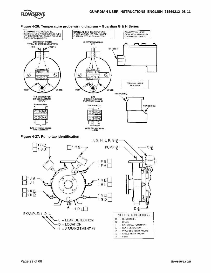
GUARDIAN USER INSTRUCTIONS ENGLISH 71569212 08-1 1
Page 29 of 68 flowserve.com
Figure 4-26: Temperature probe wiring diagram – Gua rdian G & H Series
Figure 4-27: Pump tap identification

GUARDIAN USER INSTRUCTIONS ENGLISH 71569212 08-1 1
Page 30 of 68 flowserve.com
5 COMMISSIONING, STARTUP, OPERATION AND SHUTDOWN
5.1 Pre-commission procedure Pre start-up checks Prior to starting the pump it is essential that the following checks be made. These checks are all described in detail in the Maintenance Section of this manual. • Pump and motor properly secured to the baseplate • All fasteners tightened to the correct torque, see
section 6.5 • Coupling guard in place and not rubbing • Rotation check, see section 5.4.
This is absolutely essential • Impeller clearance setting, see section 6.6 • Bearing lubrication, see section 5.2 • Bearing housing cooling system operational • Support leg cooling for centerline mounting
option operational • Heating/cooling for jacketed casing operational • Pump instrumentation is operational • Pump is primed • Rotation of shaft by hand • Remove temporary motor supports installed for
shipping (close-coupled pumps only) As a final step in preparation for operation, it is important to rotate the shaft by hand to be certain that all rotating parts move freely, and that there are no foreign objects in the pump casing. 5.2 Pump lubricants 5.2.1 Oil bath The standard bearing housing bearings are oil bath lubricated and are not lubricated by Flowserve. Before operating the pump, fill the bearing housing to the center of the oil sight glass with the proper type oil. (See Figure 5-1 for approximate amount of oil required - do not overfill.)
The oil level in the bearing housing must be maintained at ±3 mm (±1/8 in.) from the center of the sight glass. The sight glass has a 6 mm (¼ in.) hole in the center of its reflector. The bearing housing oil level must be within the circumference of the center hole to ensure adequate lubrication of the bearings. See Figure 5-2 for recommended lubricants. DO NOT USE DETERGENT OILS. The oil must be free of water, sediment, resin, soaps, acid and fillers of any kind. It should contain rust and oxidation inhibitors. The proper oil viscosity is determined by the bearing housing operating temperature as given in Figure 5-3. To add oil to the housing, clean and then remove the vent plug [6521] at the top of the bearing housing, pour in oil until it is visually half way up in the sight glass [3856]. Fill the constant level oiler bottle, if used, and return it to its position. The correct oil level is obtained with the constant level oiler in its lowest position, which results in the oil level being at the top of the oil inlet pipe nipple, or half way up in the sight glass window. Oil must be visible in the bottle at all times. Note that on ANSI 3A™ power ends there is no constant level oiler. As stated above, proper oil level is the center of the “bull’s eye” sight glass [3856]. In many pumping applications lubricating oil becomes contaminated before it loses its lubricating qualities or breaks down. For this reason it is recommended that the first oil change take place after approximately 160 hours of operation, at which time, the used oil should be examined carefully for contaminants. During the initial operating period monitor the bearing housing operating temperature. Record the external bearing housing temperature. See Figure 5-4 for maximum acceptable temperatures. The normal oil change interval is based on temperature and is shown in Figure 5-5. Figure 5-1: Amount of oil required
Pump Guardian G & H Series pumps Group 1 240 ml (8.1 oz)
Group 2 545 ml (18.4 oz)

GUARDIAN USER INSTRUCTIONS ENGLISH 71569212 08-1 1
Page 31 of 68 flowserve.com
Figure 5-2: Recommended oil lubricants Oil Splash / force feed / purge oil mist/ pure oil mist lubrication
Viscosity cSt @ 40 ºC
32 46 68
Oil temperature range * -5 to 65 ºC (23 to 149 ºF)
-5 to 78 ºC (23 to 172 ºF)
-5 to 80 ºC (23 to 176 ºF)
Cen
trifu
gal p
ump
lubr
icat
ion
Designation to ISO 3448 and DIN51524 part 2
ISO VG 32 32 HLP
ISO VG 46 46 HLP
ISO VG 68 68 HLP
BP Castrol † Energol HLP-HM 32 Energol HLP-HM 46 Energol HLP-HM 68 ESSO † NUTO HP 32 NUTO HP 46 NUTO HP 68
ELF/Total † ELFOLNA DS 32 Azolla ZS 32
ELFOLNA DS 46 Azolla ZS 46
ELFOLNA DS 68 Azolla ZS 68
LSC (for oil mist)** LSO 32 (Synthetic oil) LSO 46 (Synthetic oil) LSO 68 (Synthetic oil) ExxonMobil † Mobil DTE 24 Mobil DTE 25 Mobil DTE 26
Q8 † Q8 Haydn 32 Q8 Haydn 46 Q8 Haydn 68 Shell † Shell Tellus 32 Shell Tellus 46 Shell Tellus 68
Chevron Texaco † Rando HD 32 Rando HD 46 Rando HD 68 Wintershall (BASF Group) † Wiolan HS32 Wiolan HS46 Wiolan HS68
Oil
com
pani
es a
nd
lubr
ican
ts
Fuchs † Renolin CL 32 Renolin CL 46 Renolin CL 68 * Note that it normally takes 2 hours for bearing temperature to stabilize and the final temperature will depend on the ambient, r/min, pumpage temperature and pump size. Also some oils have a very low pour point and good viscosity index which extend the minimum temperature capability of the oil. Always check the grade capability where the ambient is less than -5 ºC (23 ºF). † Use LSC for oil mist. Oil parameters provide flash point >166 ºC (331 ºF), density >0.87 @ 15 ºC (59 ºF), pour point of -10 ºC (14 ºF) or lower. ** Normal compounded oils CANNOT be used with oil mist as anti-foam additives need to be avoided. Most oils recommended for wet splash lubrication contain foam inhibitors as well as antioxidants and anticorrosion additives, so they are unsuitable for oil mist. Some synthetic lubricants may attack the Nitrile seals used in a regular bearing housing. Figure 5-3: Oil viscosity grades
Maximum oil temperature
ISO viscosity grade
Minimum viscosity index
Up to 71 °C (160 °F) 46 95 71-80 °C (160-175 °F) 68 95 80-94 °C (175-200 °F) 100 95
Figure 5-4: Maximum external housing temperatures
Lubrication Temperature Oil bath 82 °C (180 °F) Oil mist 82 °C (180 °F) Grease 94 °C (200 °F)
The maximum temperature that the bearing can be exposed to is 105 °C (220 °F). Figure 5-5: Lubrication intervals *
Lubricant Under 71 °C (160 °F)
71-80 °C (160-175 °F)
80-94 °C (175-200 °F)
Mineral oil 6 months 3 months 1.5 months
Synthetic oil ** 18 months 18 months 18 months * Assuming good maintenance and operation practices, and no
contamination. ** May be increased to 36 months with ANSI 3A™ power end.
5.2.2 Grease for life double shielded or double sealed bearings
These bearings are packed with grease by the bearing manufacturer and should not be relubricated. The replacement interval for these bearings is greatly affected by their operating temperature and speed. Shielded bearings typically operate cooler. 5.2.3 Oil mist When optional oil mist lubricated bearings are specified, the bearing housing is furnished with a plugged 1/2 in. NPT top inlet for connection to the user’s oil mist supply system, a vent fitting in the bearing cover, and a plugged 1/4 in. NPT bottom drain. See Oil Mist Lubrication System in Section 4.6.5.5. Do not allow oil level to remain above the center of the bearing housing sight glass window with purge mist (wet sump) systems. 5.3 Impeller clearance For Guardian G & H series pumps the impeller clearance is set to the bearing holder at 0.45 mm (0.018 in.) regardless of operating temperature. Clearance is set by adding or removing shims located between the impeller and thrust collar. See Section 6.6 for instructions on how to set the impeller.

GUARDIAN USER INSTRUCTIONS ENGLISH 71569212 08-1 1
Page 32 of 68 flowserve.com
5.4 Direction of rotation 5.4.1 Rotation check, long-coupled pumps
It is absolutely essential that the rotation of the motor be checked before connecting the shaft coupling. Incorrect rotation of the pump, for even a short time, can dislodge and damage the impeller, casing, shaft and shaft seal. All Guardian G & H series pumps turn clockwise as viewed from the motor end. A direction arrow is cast on the front of the casing as shown in Figure 5-6. Make sure the motor rotates in the same direction.
Figure 5-6: Direction of rotation arrow
5.4.2 Rotation check, close-coupled pumps This check will require operating the pump briefly, so the pump must be filled with liquid. Never run a centrifugal pump dry. To check rotation, perform the following steps: a) Open the suction and discharge valves to allow
the pump to fill with liquid. b) While watching the motor fan, bump the motor.
The proper direction of rotation for the pump is clockwise as viewed from the motor end. A direction arrow cast on the front of the casing as shown in Figure 5-6.
NEVER DO MAINTENANCE WORK WHEN THE UNIT IS CONNECTED TO POWER (Lock Out).
c) If the motor rotates in the wrong direction, reverse any two of the three leads to the motor (3 phase current). Bump the motor again to ensure the proper direction of rotation.
5.4.3 Coupling installation
The coupling (Figure 5-7) should be installed as advised by the coupling manufacturer. Pumps are shipped without the spacer installed. If the spacer has been installed to facilitate alignment, then it must be removed prior to checking rotation. Remove all protective material from the coupling and shaft before installing the coupling. Figure 5-7: Coupling
5.5 Guarding
Power must never be applied to the driver when the coupling guard is not installed. 5.5.1 Clam shell guard - standard The standard coupling guard for all Guardian G & H series pumps is the “clam shell” design and is shown in Figure 5-8. It is hinged at the top and it can be removed by loosening one of the foot bolts and sliding the support leg out from under the cap screw (note that the foot is slotted). The leg can then be rotated upward and half of the guard can be disengaged (unhinged) from the other. Note that only one side of the guard needs to be removed. To reassemble simply reverse the above procedure.
Figure 5-8 Clamshell coupling guard

GUARDIAN USER INSTRUCTIONS ENGLISH 71569212 08-1 1
Page 33 of 68 flowserve.com
Flowserve coupling guards are safety devices intended to protect workers from inherent dangers of the rotating pump shaft, motor shaft and coupling. It is intended to prevent entry of hands, fingers or other body parts into a point of hazard by reaching through, over, under or around the guard. No standard coupling guard provides complete protection from a disintegrating coupling. Flowserve cannot guarantee their guards will completely contain an exploding coupling. The coupling guard shown in Figure 5-8 conforms to the USA standard ASME B15.1, “Safety Standard for Mechanical Power Transmission Apparatus.” Flowserve manufacturing facilities worldwide conform to local coupling guard regulations. 5.5.2 ClearGuard™ - option Flowserve offers as an option a ClearGuard™, which allows you to see the condition of the coupling. (See Figure 5-9.) This guard can be used in place of the existing clamshell guard described above. The following instructions enable the user to properly fit this guard to the pump and motor.
Figure 5-9: ClearGuard™
5.5.2.1 Trimming and assembly instructions In order to correctly fit the pump/motor configuration, each ClearGuard must be trimmed to a specific length. This trimming is done on the motor end of the guard as described below. (See Figure 5-10.)
Figure 5-10: ClearGuard™ trimming
5.5.2.2 Trimming instructions a) Measure minimum distance from the center of
mounting hole in the baseplate to the motor at diameter as shown above.
b) Locate a reference center of the slot in the coupling guard flange. Transfer measurement from Step a) to the guard using this reference center.
c) Trim the motor end of guard according to the above measurement. Trimming is best done with a band saw, but most other types of manual or power saws give acceptable results. Care must be taken to ensure that there is no gap larger than 6 mm (0.24 in.) between the motor and the coupling guard.
d) Note: If motor diameter is smaller than guard diameter, trim guard so that it extends over the end of the motor as far as possible.
e) Deburr the trimmed end with a file or a sharp knife. Care must be taken to eliminate all sharp edges.
5.5.2.3 Assembly instructions f) Place the bottom and top halves of the
ClearGuard around the coupling. g) Install the support legs by inserting and then
rotating the top flange of the leg through the slot in the shell flange until it comes all the way through and locks the top and bottom together.
h) Attach the support legs to the baseplate using the fasteners and washers provided.
i) Install fasteners in the holes provided to secure the guard flanges together.
5.6 Priming and auxiliary supplies The standard Guardian G & H series pumps will not move liquid unless the pump is primed. A pump is said to be “primed” when the casing and the suction piping are completely filled with liquid. Open discharge valves a slight amount. This will allow any entrapped air to escape and will normally allow the pump to prime, if the suction source is above the pump. When a condition exists where the suction pressure may drop below the pump’s capability, it is advisable to add a low-pressure control device to shut the pump down when the pressure drops below a predetermined minimum. The Guardian Unitized self-priming centrifugal pumps have a slightly different requirement regarding priming. The initial priming liquid must be added to the pump casing until the liquid has reached the bottom of the suction nozzle. Once the initial prime is in place, the pump will automatically replenish itself and additional priming liquids are not normally needed. If liquid is lost, additional priming liquid may be needed.
GUARDIAN USER INSTRUCTIONS ENGLISH 71569212 08-1 1
Page 34 of 68 flowserve.com
5.7 Starting the pump a) Open the suction valve to full open position. It is
very important to leave the suction valve open while the pump is operating. Any throttling or adjusting of flow must be done through the discharge valve. Partially closing the suction valve can create serious NPSH and pump performance problems.
Never operate pump with both the suction and discharge valves closed. This could cause an explosion.
b) Ensure the pump is primed. (See section 5.6.) c) All cooling, heating, and flush lines must be
started and regulated. d) Start the driver (typically, the electric motor). e) Slowly open the discharge valve until the desired
flow is reached, keeping in mind the minimum continuous flow listed in section 3.4.
It is important that the discharge valve be opened within a short interval after starting the driver. Failure to do this could cause a dangerous build up of heat, and possibly an explosion.
5.8 Running or operation 5.8.1 Minimum continuous flow Minimum continuous stable flow is the lowest flow at which the pump should be operated. The minimum continuous flow (capacity) is established as a percentage of the best efficiency point (BEP). See section 3.4.4. 5.8.2 Minimum thermal flow All Guardian G & H series pumps also have a minimum thermal flow. This is defined as the minimum flow that will not cause an excessive temperature rise. Minimum thermal flow is application dependent.
Do not operate the pump below minimum thermal flow, as this could cause an excessive temperature rise. Contact a Flowserve Sales Engineer for determination of minimum thermal flow. Avoid running a centrifugal pump at drastically reduced capacities or with discharge valve closed for extended periods of time. This can cause severe temperature rise and the liquid in the pump may reach its boiling point. If this occurs, the internal process-lubricated bearings will be exposed to vapor, with no lubrication, and may be damaged or fail within a very short period of time. Continued running under these conditions when the suction valve is also
closed can create an explosive condition due to the confined vapor at high pressure and temperature. Thermostats may be used to safeguard against over heating by shutting down the pump at a predetermined temperature. Safeguards should also be taken against possible operation with a closed discharge valve, such as installing a bypass back to the suction source. The size of the bypass line and the required bypass flow rate is a function of the input horsepower and the allowable temperature rise. 5.8.3 Reduced head Note that when discharge head drops, the pump’s flow rate usually increases rapidly. Check motor for temperature rise as this may cause overload. If overloading occurs, throttle the discharge. 5.8.4 Surging condition A rapidly closing discharge valve can cause a damaging pressure surge. A dampening arrangement should be provided in the piping. 5.8.5 Operation in sub-freezing conditions When using the pump in sub-freezing conditions where the pump is periodically idle, the pump should be properly drained or protected with thermal devices which will keep the liquid in the pump from freezing. 5.9 Stopping and shutdown 5.9.1 Shutdown considerations When the pump is being shutdown, the procedure should be the reverse of the start-up procedure. First, slowly close the discharge valve, shutdown the driver, then close the suction valve. Remember that closing the suction valve while the pump is running is a safety hazard and could seriously damage the pump and other equipment. 5.9.2 Shutdown Guardian self-priming At shutdown, the liquid in the discharge piping falls back into the priming chamber and washes through the impeller into the suction. The backflow creates a siphon effect in the casing until the liquid level falls below the bottom of the suction nozzle. The inertia of the flow pulls fluid from the priming chamber to a level lower than the initial priming fill. Though the level is lower, there is still sufficient fluid in the priming chamber to allow the pump to reprime itself.

GUARDIAN USER INSTRUCTIONS ENGLISH 71569212 08-1 1
Page 35 of 68 flowserve.com
5.10 Hydraulic, mechanical and electrical duty
5.10.1 Net positive suction head (NPSH) Net positive suction head - available (NPSHA) is the measure of the energy in a liquid above the vapor pressure. It is used to determine the likelihood that a fluid will vaporize in the pump. It is critical because a centrifugal pump is designed to pump a liquid, not a vapor. Vaporization in a pump will result in damage to the pump, deterioration of the Total differential head (TDH), and possibly a complete stopping of pumping. Net positive suction head - required (NPSHR) is the decrease of fluid energy between the inlet of the pump, and the point of lowest pressure in the pump. This decrease occurs because of friction losses and fluid accelerations in the inlet region of the pump and particularly accelerations as the fluid enters the impeller vanes. The value for NPSHR for the specific pump purchased is given in the pump data sheet, and on the pump performance curve. For a pump to operate properly the NPSHA must be greater than the NPSHR. Good practice dictates that this margin should be at least 1.5 m (5 ft) or 20%, whichever is greater.
Ensuring that NPSHA is larger than NPSHR by the suggested margin will greatly enhance pump performance and reliability. It will also reduce the likelihood of cavitation, which can severely damage the pump. 5.10.2 Specific gravity (SG) Pump capacity and total head in meters (ft) of liquid do not change with SG, however pressure displayed on a pressure gauge is directly proportional to SG. Power absorbed is also directly proportional to SG. It is therefore important to check that any change in SG will not overload the pump driver or over pressurize the pump. 5.10.3 Viscosity For a given flow rate the total head reduces with increased viscosity and increases with reduced viscosity. Also for a given flow rate the power absorbed increases with the increased viscosity, and reduces with reduced viscosity. It is important that checks are made with your nearest Flowserve office if changes in viscosity are planned. 5.10.4 Pump speed Changing the pump speed affects flow, total head, power absorbed, NPSHr, noise and vibration levels. Flow varies in direct proportion to pump speed.
Head varies as speed ratio squared. Power varies as speed ratio cubed. If increasing speed it is important to ensure the maximum pump working pressure is not exceeded, the driver is not overloaded, NPSHa>NPSHr and that noise and vibration are within local requirements and regulations. 6 MAINTENANCE
It is the plant operator's responsibility to ensure that all maintenance, inspection and assembly work is carried out by authorised and qualified personnel who have adequately familiarized themselves with the subject matter by studying this manual in detail. (See also section 1.6.)
MAGNETIC FIELD PRESENT This equipment may affect electronic equipment or other devices that are influenced by magnetic fields. Because magnetic drive pumps contain powerful magnets, anyone with a pacemaker MUST NOT disassemble these pumps nor enter areas where disassembled pumps are likely to be. Also, keep all credit cards, bank cards, watches, computer disks and anything else which can be damaged by magnetic fields away from these pumps when disassembled. Any work on the machine must be performed when it is at a standstill. It is imperative that the procedure for shutting down the machine is followed, as described in section 5.9. On completion of work all guards and safety devices must be re-installed and made operative again. Before restarting the machine, the relevant instructions listed in section 5, Commissioning, start up, operation and shut down, must be observed.
Oil and grease leaks may make the ground slippery. Machine maintenance must always begin and finish by cleaning the ground and the exterior of the machine. If platforms, stairs and guard rails are required for maintenance, they must be placed for easy access to areas where maintenance and inspection are to be carried out. The positioning of these accessories must not limit access or hinder the lifting of the part to be serviced. When air or compressed inert gas is used in the maintenance process, the operator and anyone in the vicinity must be careful and have the appropriate protection.

GUARDIAN USER INSTRUCTIONS ENGLISH 71569212 08-1 1
Page 36 of 68 flowserve.com
Do not spray air or compressed inert gas on skin. Do not direct an air or gas jet towards other people. Never use air or compressed inert gas to clean clothes. Before working on the pump, take measures to prevent the pump from being accidentally started. Place a warning sign on the starting device: "Machine under repair: do not start" . With electric drive equipment, lock the main switch open and withdraw any fuses. Put a warning sign on the fuse box or main switch: "Machine under repair: do not connect". Never clean equipment with flammable solvents or carbon tetrachloride. Protect yourself against toxic fumes when using cleaning agents. Refer to the parts list shown in section 8 for item number references used throughout this section. 6.1 Maintenance schedule It is recommended that a maintenance plan and schedule be implemented, in accordance with these User Instructions, to include the following: • Any auxiliary systems installed must be monitored,
if necessary, to ensure they function correctly. • Check for any leaks from gaskets and seals. • Check bearing lubricant level, and the remaining
hours before a lubricant change is required. • Check that the duty condition is in the safe
operating range for the pump. • Check vibration, noise level and surface
temperature at the bearings to confirm satisfactory operation.
• Check dirt and dust is removed from areas around close clearances, bearing housings and motors.
• Check coupling alignment and align if needed. 6.1.1 Preventive maintenance The following sections of this manual give instructions on how to perform a complete maintenance overhaul. However, it is also important to periodically repeat the Pre start-up checks listed in section 5.1. These checks will help extend pump life as well as the length of time between major overhauls. 6.1.2 Need for maintenance records A procedure for keeping accurate maintenance records is a critical part of any program to improve pump reliability. There are many variables that can contribute to pump failures. Often long term and repetitive problems can only be solved by analyzing these variables through pump maintenance records.
6.1.3 Cleanliness One of the major causes of pump failure is the presence of contaminants in the bearing housing. This contamination can be in the form of moisture, dust, dirt and other solid particles such as metal chips. Dirt in the impeller threads could cause the impeller to not be seated properly against the shaft. This, in turn, could cause a series of other problems. For these reasons, it is very important that proper cleanliness be maintained. Some guidelines are listed below: • After draining the oil from the bearing housing,
periodically send it out for analysis. If it is contaminated, determine the cause and correct.
• The work area should be clean and free from dust, dirt, oil, grease etc.
• Hands and gloves should be clean. • Only clean towels, rags, and tools should be used. 6.2 Spare parts The decision on what spare parts to stock varies greatly depending on many factors such as the criticality of the application, the time required to buy and receive new spares, the erosive/corrosive nature of the application, and the cost of the spare part. Section 8 identifies all of the components that make up each pump addressed in this manual. Please refer to the Flowserve Mark 3 Pump Parts Catalog for more information. A copy of this book can be obtained from your local Flowserve Sales Engineer or Distributor/Representative.
Prior to resizing impellers in nickel, please consult your local Flowserve sales representative. 6.2.1 Ordering of spare parts Flowserve keeps records of all pumps that have been supplied. Spare parts can be ordered from your local Flowserve Sales Engineer or from a Flowserve Distributor or Representative. When ordering spare parts the following information should be supplied:
1) Pump serial number 2) Pump size and type 3) Part name – see section 8 4) Part item number – see section 8 5) Material of construction (alloy) 6) Number of parts required
The pump size and serial number can be found on the name plate located on the bearing housing. (See Figure 3-1.)
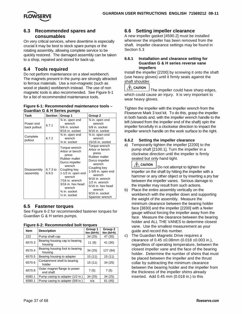
GUARDIAN USER INSTRUCTIONS ENGLISH 71569212 08-1 1
Page 37 of 68 flowserve.com
6.3 Recommended spares and consumables
On very critical services, where downtime is especially crucial it may be best to stock spare pumps or the rotating assembly, allowing complete service to be quickly restored. The damaged assembly can be taken to a shop, repaired and stored for back-up. 6.4 Tools required Do not perform maintenance on a steel workbench. The magnets present in the pump are strongly attracted to ferrous materials. Use a non-magnetic (such as wood or plastic) workbench instead. The use of non magnetic tools is also recommended. See Figure 6-1 for a list of recommended maintenance tools. Figure 6-1: Recommended maintenance tools – Guardian G & H Series pumps Task Section Group 1 Group 2
Power end back pullout
6.7.1
¾ in. open end wrench
5/8 in. socket 9/16 in. socket
¾ in. open end wrench
5/8 in. socket 9/16 in. socket
Complete pullout 6.7.2
¾ in. open end wrench
¾ in. socket
¾ in. open end wrench
15/16 in. socket
Disassembly /assembly
6.7.3 to 6.9.5
Torque wrench Arbor or bench
press Rubber mallet Durco impeller
wrench Coupling key 1-1/2 in. open end
wrench 7/16 in. wrench 3/16 in. hex head
wrench ¾ in. socket ½ in. socket
Torque wrench Arbor or bench
press Rubber mallet Durco impeller
wrench Coupling key 1-5/8 in. open end
wrench 9/16 in. wrench 1/2 in. wrench 5/16 in. hex head
wrench 9/16 in. socket Spanner wrench
6.5 Fastener torques See Figure 6-2 for recommended fastener torques for Guardian G & H series pumps. Figure 6-2: Recommended bolt torques
Item Description Group 1 Nm (lbf•ft)
Group 2 Nm (lbf•ft)
222 Pump shaft cap 34 (25) 47 (35)
6570.3 Bearing housing cap to bearing housing
11 (8) 41 (30)
6570.4 Bearing housing foot to bearing housing
34 (25) 127 (94)
6570.5 Bearing housing to adapter 15 (11) 15 (11)
6570.6 Containment shell to bearing holder
15 (11) 34 (25)
6570.8 Outer magnet flange to power end shaft
7 (5) 7 (5)
6580.1 Pump casing to adapter (1/2 in.) 34 (25) 34 (25) 6580.1 Pump casing to adapter (5/8 in.) n/a 61 (45)
6.6 Setting impeller clearance A new impeller gasket [4590.2] must be installed whenever the impeller has been removed from the shaft. Impeller clearance settings may be found in Section 5.3 6.6.1 Installation and clearance setting for
Guardian G & H series reverse vane impellers
Install the impeller [2200] by screwing it onto the shaft (use heavy gloves) until it firmly seats against the shaft shoulder.
The impeller could have sharp edges, which could cause an injury. It is very important to wear heavy gloves. Tighten the impeller with the impeller wrench from the Flowserve Mark 3 tool kit. To do this, grasp the impeller in both hands and, with the impeller wrench handle to the left (viewed from the impeller end of the shaft) spin the impeller forcefully in a clockwise direction to impact the impeller wrench handle on the work surface to the right. 6.6.2 Setting the impeller clearance a) Temporarily tighten the impeller [2200] to the
pump shaft [2100.1]. Turn the impeller in a clockwise direction until the impeller is firmly seated but only hand tight.
Do not attempt to tighten the impeller on the shaft by hitting the impeller with a hammer or any other object or by inserting a pry bar between the impeller vanes. Serious damage to the impeller may result from such actions.
b) Place the entire assembly vertically on the workbench with the impeller down and supporting the weight of the assembly. Measure the minimum clearance between the bearing holder face [3830] and the impeller [2200] with a feeler gauge without forcing the impeller away from the face. Measure the clearance between the bearing holder and ALL THE VANES to determine closest vane. Use the smallest measurement as your guide and record this number.
c) The Guardian Magnetic Drive requires a clearance of 0.45 ±0.08mm (0.018 ±0.003 in.), regardless of operating temperature, between the closest impeller vane and the face of the bearing holder. Determine the number of shims that must be placed between the impeller and the thrust collar by subtracting the minimum clearance between the bearing holder and the impeller from the thickness of the impeller shims already inserted. Add 0.45 mm (0.018 in.) to this

GUARDIAN USER INSTRUCTIONS ENGLISH 71569212 08-1 1
Page 38 of 68 flowserve.com
difference. This number is the thickness of shims that are required to adjust the impeller. For example, if the initial measurement between the closest impeller vane and the bearing holder face is 0.75 mm (0.030 in.), and the thickness of the shims already inserted is 1.00 mm (0.040 in.), use
1.00 mm – 0.75 mm = 0.25 mm (0.040 in. – 0.030 in. = 0.010 in.)
Next, add 0.45 mm (0.018 in.) to 0.25 mm (0.010 in.) to determine the thickness of the shims required to adjust the impeller properly.
0.25 mm + 0.45 mm = 0.70 mm (0.010 in. + 0.018 in. = 0.028 in.)
A combination of shims equal to 0.70 mm (0.028 in.) thickness would then be required to set the impeller properly.
d) Set the assembly back to horizontal. Remove the impeller and the 1.00 mm (0.040 in.) combination of shims from the pump shaft. Removal should only require using your hands since the impeller was only hand tightened. If necessary, use the Durco impeller wrench to hold the shaft stationary.
e) Place the required number of shims against the shoulder in the thrust collar [3610] or thrust collar ring [207]. Thread the impeller back onto the pump shaft and tighten as described in step 1. Make sure the shims sit flat between mating faces.
f) Recheck the impeller clearance as described in step b). If the distance is more or less than required, repeat steps c) through f) until clearance is correct.
g) When the clearance is properly set, set the assembly back to horizontal. Remove the impeller and thrust collar [3610]. Group 1. Place the thrust collar/pump shaft O-ring [4610.4] in the groove on the back side of the thrust collar. Stretch the thrust collar ring/O-ring [4610.5] over the hub on the backside of the impeller. Group 2. Remove the thrust collar ring and shims from the thrust collar. Place the thrust collar/ring O-ring [4610.5] into the O-ring groove on the shimming side of the thrust collar. Using an arbor press, press the thrust collar ring and shims into the thrust collar. In order to keep the shims from falling out of the thrust collar during this press, the ring should be placed on the work surface with the thrust collar on top of it. Place the thrust collar/pump shaft O-ring [4610.4] into the groove on the pump shaft side of the thrust collar. Place the thrust collar into the bearing holder [3830] so the thrust journal sits flat on the grooved portion of the T-shaped bushing [3300.1].
h) Install new impeller gasket (4590.2) and tighten the impeller until it is firmly seated.
Failure to tighten the impeller sufficiently may allow liquid to reach the impeller thread. Additionally, a loose impeller will be tightened when the pump is started, but may be very difficult to remove later.
The impeller will be difficult to turn because there is deformation of the O-rings during seating of the impeller.
6.7 Disassembly a) Before performing any maintenance, disconnect the
driver from its power supply and lock it off line.
Lock out power to driver to prevent personal injury.
b) Close the discharge and suction valves, and drain all liquid from the pump.
c) Close all valves on auxiliary equipment and piping, then disconnect all auxiliary piping.
d) Decontaminate the pump as necessary.
If Flowserve Guardian G & H series pumps contain dangerous chemicals, it is important to follow plant safety guidelines to avoid personal injury or death.
6.7.1 Power end removal without breaking
process containment At this point, it may be necessary to detach some of the instrumentation.
By following the steps in sections 6.7.1.1 or 6.7.1.2, the process fluid is contained and the power end can be completely removed. This procedure does not preclude the use of personal protective gear. Personnel should follow their standard plant safety practices. 6.7.1.1 Long-coupled Guardian G & H series
pumps
Figure 6-3A: Power end removal with process contained by wet end

GUARDIAN USER INSTRUCTIONS ENGLISH 71569212 08-1 1
Page 39 of 68 flowserve.com
a) Remove coupling guard. b) Remove the spacer coupling. c) Loosen the cap screw(s) holding the bearing
housing foot to the baseplate. d) To remove the power end from the wet end,
remove the four (4) bearing housing/adapter fasteners [6570.5]. The magnetic coupling will remain connected due to the radial and axial forces of the magnets.
e) Screw the four (4) square head jackbolts [6575] in the bearing housing through the threaded taps until each comes into contact with the adapter. Continue to screw all jackbolts in evenly to detach the wet end from the power end. (Figure 6-3A.)
Do not attempt to remove the power end by any other method. The magnetic force can cause severe personal injury.
Be sure to separate the inner and outer magnet assemblies evenly. Cocking of the two can result in serious damage to the magnets and/or containment shell. It is best to alternatively give each bolt a turn to ensure proper and even separation.
Depending on pump size and magnet length, it may be necessary to move the motor to complete step e).
f) To disassemble the power end, follow steps a) through g) in Section 6.7.5.
6.7.1.2 Close-coupled Guardian G & H series
pumps
Figure 6-3B a) Loosen the fasteners (if applicable) holding the
motor to the baseplate. b) Remove the four (4) fasteners [6570.10] that hold
the motor flange [251] to the lantern [3132]. c) Engage the two (2) square head jackscrews [6575]
that are located at the 3 o’clock and 9 o’clock positions on the lantern [3132] until each jackscrew comes in contact with the motor flange [251].
Continue to screw both jackscrews evenly to disengage the motor from the wet end of the pump. (See Figure 6-3B.) It is best to alternate from one jackscrew to the other to ensure even separation.
Do not attempt to remove the motor/outer magnet assembly from the wet end by any other method. The magnetic force can cause severe personal injury.
d) To complete the disassembly of the close-coupled drive end, see Section 6.7.5.2.
6.7.2 Removing the entire pump assembly from
the casing
Small amounts of liquid may be trapped in the casing and/or containment area. Proper decontamination is the responsibility of the user.
Drain and flush the pump before proceeding to Sections 6.7.2.1 or 6.7.2.2. The Guardian Magnetic Drive pump is designed to handle corrosive, toxic, and hazardous process fluids and may need to be decontaminated prior to any disassembly. 6.7.2.1 Long-coupled Guardian G & H series
pumps Figure 6-4: Removing entire pump assembly from casing
a) Remove the spacer from the spacer coupling. b) For the larger pumps, attach lifting equipment to
the pump. Place the equipment in light tension to support the pump when it is removed from the casing.
c) All maintenance can be performed without casing removal from the piping. To remove the back pullout pump assembly from the casing, remove all casing fastener nuts [6580] from the casing/adapter fasteners [6572]. (Figure 6-4.)
d) Remove the cap screw(s) holding the bearing housing foot to the baseplate.
e) Move the back pullout pump assembly toward the motor and rotate the unit out, leaving the casing in place. (Figure 6-4.)

GUARDIAN USER INSTRUCTIONS ENGLISH 71569212 08-1 1
Page 40 of 68 flowserve.com
In the event the pump assembly is lodged in the casing, two jackscrew locations 180 degrees apart are provided on the adapter [1340]. Inspect the casing [1100] and the face of the bearing holder for wear, corrosion, or defects. Remove the bearing holder/casing gasket [4590.1]. It is recommended that all O-rings and gaskets be replaced each time the pump is disassembled.
f) The entire pump without the casing [1100] can now be moved to the repair shop.
6.7.2.2 Close-coupled Guardian G & H series
pumps
Figure 6-5: Removing entire pump less casing
a) Drain and flush the pump. The Guardian
Magnetic Drive pump is designed to handle corrosive, toxic, and hazardous process fluids and may need to be decontaminated prior to any disassembly.
b) Remove the motor/outer magnet assembly by following the steps outlined in Section 6.7.1.2.
c) All maintenance can be performed without removing the casing from the piping. To remove the pump assembly from the casing, remove all casing fastener nuts [6580] from the casing/adapter fasteners [6572].
d) Remove the capscrew holding the lantern foot to the baseplate (if applicable).
e) Move the pump assembly back from the casing and rotate the unit out of the casing. (Figure 6-5.) In the event the pump assembly is lodged in the casing, two jackscrew locations 180 º apart are provided on the adapter [1340].
f) Inspect the casing [1100] and the face of the bearing holder [3830] for wear, corrosion, or defects. Remove the bearing holder/casing gasket [4590.1]. It is recommended that all o-rings and gaskets be replaced each time the pump is disassembled.
g) The entire pump without the casing [1100] can now be moved to the repair shop.
h) To remove the lantern [3132] from the wet end, orient the back pullout assembly vertically on the impeller. (Figure 6-6.) Remove the four (4) lantern/adapter fasteners [6570.5]. Remove the lantern [3132] by lifting it straight up from the adapter [1340].
Figure 6-6: Lantern removal
The lantern [3132] is manufactured from ductile cast iron and may attach to the containment shell [224] upon removal due to attraction of the inner magnet assembly.
i) The entire pump without the casing [1100] can now be moved to the repair shop.
6.7.3 Detaching the wet end from the power end At this point, it may be necessary to detach some of the instrumentation. a) To remove the power end from the wet end, remove
the four (4) bearing housing/adapter fasteners [6570.5]. (Figures 6-3A & B.) The magnetic coupling will remain connected due to the magnetic forces.
b) Screw the four (4) square head jackbolts [6575] in the bearing housing [3200] through the threaded holes until each comes into contact with a recessed hole in the adapter [1340]. For close coupled pumps, there are only two (2) jackbolts [6575]. Continue to screw all jackbolts in evenly to detach the wet end from the power end.
Do not attempt to remove the power end from the wet end by any other method. The magnetic force can cause severe personal injury.
Be sure to separate the inner and outer magnet assemblies evenly. Cocking of the two can result in serious damage to the magnets and/or containment shell. It is best to alternately give each bolt a turn to ensure proper and even separation.
6.7.4 Disassembling the wet end Handle the journal and bushing materials with care. These parts are easily chipped and damaged. a) Remove the six (6) retainer ring/containment
shell fasteners [6570.6]. Remove the retainer ring [228]. In case the retainer ring [228] is lodged in place, two jackscrew locations are provided to aid in removal. (Figure 6-7.)
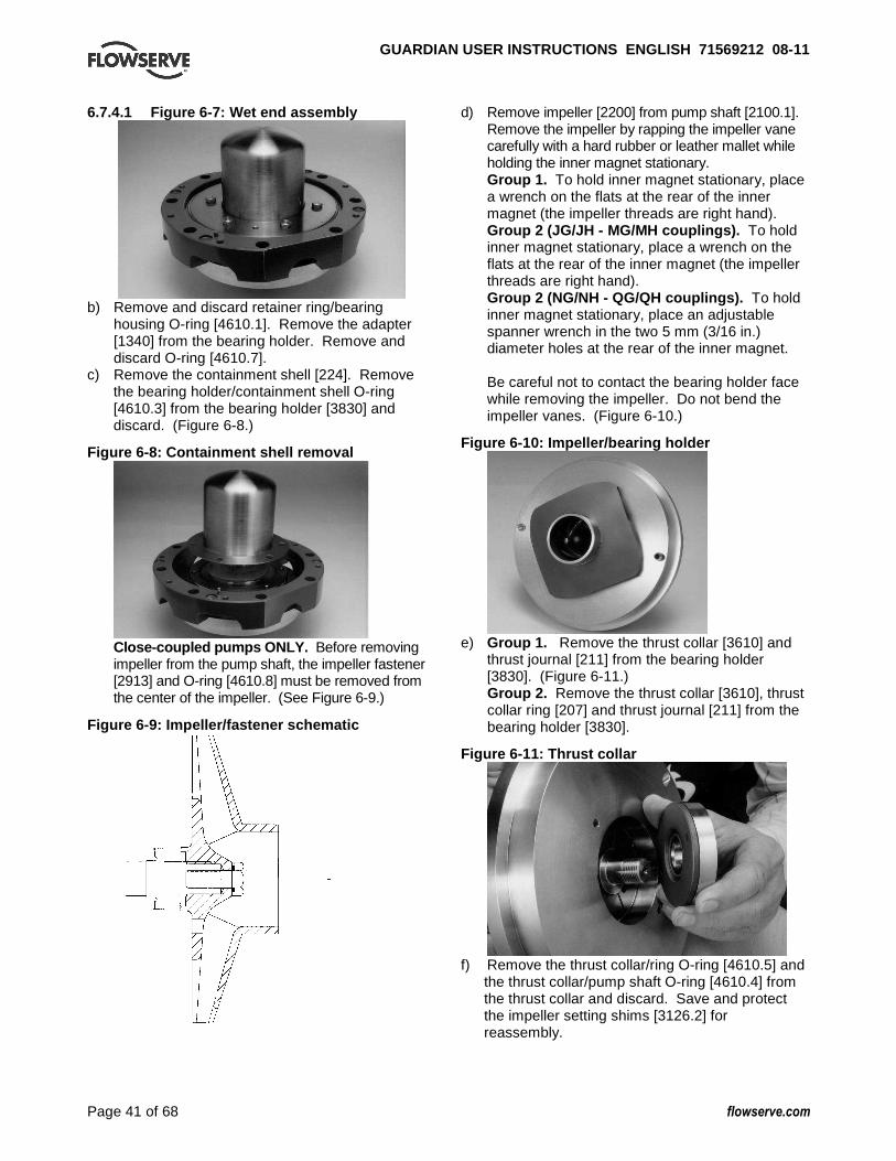
GUARDIAN USER INSTRUCTIONS ENGLISH 71569212 08-1 1
Page 41 of 68 flowserve.com
6.7.4.1 Figure 6-7: Wet end assembly
b) Remove and discard retainer ring/bearing
housing O-ring [4610.1]. Remove the adapter [1340] from the bearing holder. Remove and discard O-ring [4610.7].
c) Remove the containment shell [224]. Remove the bearing holder/containment shell O-ring [4610.3] from the bearing holder [3830] and discard. (Figure 6-8.)
Figure 6-8: Containment shell removal
Close-coupled pumps ONLY. Before removing impeller from the pump shaft, the impeller fastener [2913] and O-ring [4610.8] must be removed from the center of the impeller. (See Figure 6-9.)
Figure 6-9: Impeller/fastener schematic
d) Remove impeller [2200] from pump shaft [2100.1]. Remove the impeller by rapping the impeller vane carefully with a hard rubber or leather mallet while holding the inner magnet stationary. Group 1. To hold inner magnet stationary, place a wrench on the flats at the rear of the inner magnet (the impeller threads are right hand). Group 2 (JG/JH - MG/MH couplings). To hold inner magnet stationary, place a wrench on the flats at the rear of the inner magnet (the impeller threads are right hand). Group 2 (NG/NH - QG/QH couplings). To hold inner magnet stationary, place an adjustable spanner wrench in the two 5 mm (3/16 in.) diameter holes at the rear of the inner magnet. Be careful not to contact the bearing holder face while removing the impeller. Do not bend the impeller vanes. (Figure 6-10.)
Figure 6-10: Impeller/bearing holder
e) Group 1. Remove the thrust collar [3610] and
thrust journal [211] from the bearing holder [3830]. (Figure 6-11.) Group 2. Remove the thrust collar [3610], thrust collar ring [207] and thrust journal [211] from the bearing holder [3830].
Figure 6-11: Thrust collar
f) Remove the thrust collar/ring O-ring [4610.5] and
the thrust collar/pump shaft O-ring [4610.4] from the thrust collar and discard. Save and protect the impeller setting shims [3126.2] for reassembly.

GUARDIAN USER INSTRUCTIONS ENGLISH 71569212 08-1 1
Page 42 of 68 flowserve.com
g) Remove the inner magnet [220] and pump shaft (2100.1) from the bearing holder [3830]. Keep the shaft in line with the bearing holder as it is removed so as to avoid cocking the assembly in the holder. (Figure 6-12.) Avoid prying or tapping the assembly when removing.
Figure 6-12: Inner magnet/shaft assembly
h) Remove the T-shaped outboard bushing [216] from
the bearing holder [3830]. (Figure 6-13.) H Series pumps utilize an alloy cartridge to hold both the inboard [212] and outboard bushing [216] in the bearing holder. These cartridges are assembled at the factory. Do not attempt to disassemble bushing from cartridge. (Figure 6-14.)
Figure 6-13: Bearing holder with outboard bushing
Group 1 inboard and outboard bushings and thrust journals are NOT interchangeable. Group 2 inboard and outboard bushings are interchangeable – be sure to mark inboard vs. outboard upon removal for later evaluation. Group 2 inboard and outboard thrust journals are NOT interchangeable. Remove the inboard T-shaped bushing [212] from the bearing holder.
Figure 6-14: Bushings
If disassembly of the inner magnet assembly/pump shaft is required, follow steps i) and j). Disassembly is necessary if the pump shaft [2100.1] or inner magnet [220] needs to be replaced. Otherwise, skip to Section 6.7.5.
Newer Guardian pumps have shaft caps [222] that are LEFT HAND thread. These are indicated by an “LH” stamped into the end of the cap. Older pumps that do not have the “LH” marking utilize right hand threads. All replacement shafts/caps will have left hand threads.
i) Unscrew the pump shaft cap [222]. Remove the cap/inner magnet O-ring [4610.6] and discard. Pull the pump shaft out and remove the pump shaft key [6700.2]. Remove the pump shaft gasket [4590.6] and discard. Remove the silicon carbide thrust journal [217] from the inner magnet assembly [220]. (Figure 6-15.) If the silicon carbide journal is lodged in place, use the two holes in the inner magnet to push the journal out. If the pump shaft or pump shaft journal [213] does not need replacement, stop here and do not perform step j) because the wet end disassembly is complete. However, if the pump shaft or pump shaft journal does need replacement, proceed to step j).
Figure 6-15: Outboard thrust journal
Wear eye/hand protection as shaft journal is broken.

GUARDIAN USER INSTRUCTIONS ENGLISH 71569212 08-1 1
Page 43 of 68 flowserve.com
j) To remove the pump shaft journal [213] from the pump shaft [2100.1]. (Figure 6-16.) Wrap the part in a rag and strike the pump shaft journal [213] with a hard object to break it. Remove the shaft gasket [4590.6] and discard. (Figure 6-17.) Remove the tolerance rings [241] and discard.
Do not reuse the tolerance rings. The disassembly of the wet end is now complete.
Figure 6-16: Group 1 pump shaft/journal assembly
Figure 6-17: Group 1 shaft with mounted tolerance rings
Figure 6-18: Group 2 shaft with mounted tolerance rings
Figure 6-19: Group 1 shaft with unmounted tolerance rings
Figure 6-20: “Oil level must be maintained at center of sight glass”
6.7.5 Disassembling the power end
Be aware of strong magnetic forces of the outer magnets. Keep magnetic material away from these magnets. Observe previous warnings concerning these magnets. 6.7.5.1 Long-coupled Guardian G & H series
pumps Figure 6-21: Power end major components
This procedure is necessary if the outer magnet assembly, anti-friction bearings or oil seals must be replaced. See Figure 6-52 for recommendations on ball bearing relubrication intervals. a) Drain the oil in the bearing housing by removing
the bearing housing drain plug [6569.1]. Put the bearing housing drain plug back into place after the bearing housing is drained.
b) Remove reverse rotation screw [6570.8] with hex head wrench. The threads are right hand.
c) Unscrew the outer magnet/flange assembly [230/231] from the drive shaft [2100.2]. Mount the drive shaft/coupling key [6700] and a Durco impeller wrench on the shaft. With the wrench handle pointing to the right when viewed from the magnet side of the bearing housing [3200], grasp the magnet firmly.

GUARDIAN USER INSTRUCTIONS ENGLISH 71569212 08-1 1
Page 44 of 68 flowserve.com
Spin it rapidly in a counterclockwise direction so that the wrench handle makes a solid impact with the work surface to the left of the housing. After several sharp raps, the outer magnet/flange assembly should be free and easily removed. It is recommended that the magnet assemblies be stored in plastic bags to avoid the necessity to clean later.
The threads are right hand. d) Remove the three (3) bearing cover fasteners
[6570.3] and bearing cover [3260]. Remove the bearing cover/bearing housing O-ring [4610.2] and discard. Pull the drive shaft and bearing assembly out of the bearing housing in one straight motion. Avoid cocking the assembly in the housing. Remove the wavy washer [127A]. (Figure 6-21.)
e) If the pump is provided with oil lip seals, it is recommended that these items be replaced during each pump rebuild. Lip seals [4310.1, 4310.2] can be removed from the bearing housing using an arbor press or tapped out using a flat punch.
f) If necessary, remove the bearing housing foot [3134] by unscrewing the footpiece fastener [6570.4] from the bearing housing. A shim [3126.1] may also be present.
g) If the ball bearings [3011, 3013] need to be replaced, remove the bearings from the drive shaft. If the bearings are to be replaced and the drive shaft reused, extra care should be taken so as not to damage the drive shaft. Remove the bearings with a bearing puller. Even pressure should be applied to the inner bearing race only. It is recommended that the bearings not be reused if they are removed from the drive shaft.
Keep contaminants out of the bearing housing and bearings.
h) The power end disassembly is complete. 6.7.5.2 Close-coupled Guardian G & H series
pumps – outer magnet/motor disassembly
This procedure is necessary only if the outer magnet assembly [230/231] or motor must be replaced. a) Loosen the set screw the attaches the outer
magnet assembly [230/231] to the motor shaft. (See Figure 6-22.)
b) Remove the outer magnet assembly [230/231] from the motor shaft. As a disassembly aide, a threaded hole has been provided in the center of the outer magnet flange [231] to enable the outer magnet flange to be jacked off of the motor shaft.
One of the square head jackscrews [6575] from the lantern [3132] can be used for this step.
c) Remove the fasteners that attach the outer magnet flange [231] to the hub [245].
d) To remove the motor flange [251] from the motor, remove the four (4) motor flange/motor fasteners [6570.11].
Figure 6-22: Outer magnet/motor assembly
e) Outer magnet/motor disassembly is complete. 6.8 Examination of parts Cleaning/inspection Clean all of the parts using a non-flammable solvent cleaner and inspect them for damage, wear and corrosion. Replace worn with new genuine Flowserve parts. Clean all the O-ring grooves thoroughly and remove any burrs from the grooves. The pump shaft journal should be carefully inspected. Particular attention should be given to the impeller threads, lip seals, magnetic coupling and all bearings.
It is important that only non-flammable, non-contaminated cleaning fluids are used. These fluids must comply with plant safety and environmental guidelines. Critical measurements and tolerances To maximize reliability of pumps, it is important that certain parameters and dimensions are measured and maintained within specified tolerances. It is important that all parts be checked. Any parts that do not conform to the specifications should be replaced with new Flowserve parts. Parameters that should be checked by users Flowserve recommends that the user check the following measurements and tolerances whenever pump maintenance is performed. Each of these measurements is described in more detail on the following pages.

GUARDIAN USER INSTRUCTIONS ENGLISH 71569212 08-1 1
Page 45 of 68 flowserve.com
6.8.1 Wet end a) Inspect the casing, impeller, bearing holder and
inner magnet for wear, corrosion and defects. b) Inspect the pins in the inner magnet, bearing
holder and thrust collar for diametrical wear. The nominal diameter of these pins is 4.737 mm (0.1865 in.). Replace these pins if diametrical wear exceeds 0.508 mm (0.020 in.). These pins must be press fit using an arbor press. The height of the pins above the surface they are pressed into must not exceed 2.92 mm (0.115 in.) but not be less than 2.16 mm (0.085 in.).
c) Inspect the bushings and thrust journals for wear. Measure the thickness of the inboard thrust journal and the thickness of the flange on the inboard bushing. The nominal thicknesses for these parts can be found in Figure 6-23. If the sum of the axial wear on these two parts exceeds 0.38 mm (0.015 in.), replace these parts immediately. Repeat this inspection for the outboard bushing and outboard thrust journal. The sum of the axial wear must not exceed 0.38 mm (0.015 in.) on the outboard components.
d) Inspect the shaft journal and bushings for diametrical wear. Total diametrical wear must not exceed 0.610 mm (0.024 in.). Measure the outside diameter of the shaft journal and the inside diameter of the bushings. The nominal diameters for these parts can be found in Figure 6-23. If the sum of the wear on the shaft journal and its corresponding bushing exceeds the allowable diametrical wear, identify the worn parts and replace them immediately.
Figure 6-23: Wet end bearings allowable wear Total axial allowable wear 0.38 mm (0.015 in.) Total diametrical allowable wear 0.61 mm (0.024 in.)
BUSHING AND JOURNAL DIMENSIONS AS NEW
Thrust journal
thickness I.B. O.B.
Bushing flange
thickness
Bushing I.D.
Shaft journal O.D.
Group 1 4.737
(0.1865) 6.337
(0.2495) 9.45
(0.372) 34.938
(1.3755) 34.87
(1.373)
Group 2 4.737
(0.1865) 4.737
(0.1865) 9.45
(0.372) 47.377
(1.8755) 47.536
(1.8715)
Note: Dimensions shown above are in millimeters (inches).
e) Inspect the containment shell to ensure the allowable corrosion limit has not been exceeded. The containment shell thickness is 1.27 mm (0.050 in.) as new and the allowable corrosion is 0.635 mm (0.025 in.), 150 lb Class [0.508 mm (0.020 in.), 300 lb Class].
f) All wet end O-rings and gaskets must be replaced. Inspect O-ring grooves for integrity. It is good practice to replace all O-rings.
6.8.2 Power end a) Inspect the outer magnet rub pads for wear. The
height of the rub pads above the magnet outer diameter is 1.0 mm (0.04 in.) as new. If wear is greater than 0.5 mm (0.02 in.), then the rub pads should be replaced. The primary cause of worn rub pads is an anti-friction bearing failure.
b) Inspect the anti-friction bearings for scoring, pitting, scratching and rusting.
Use of replacement parts not provided by Flowserve may result in premature pump failure, excessive damage to equipment, or personal injury. Use of non OEM or remanufactured parts voids all warranties provided.
Additional parameters checked by Flowserve The parameters listed below are somewhat more difficult to measure and/or may require specialized equipment. For this reason, they are not typically checked by our customers, although they are monitored by Flowserve during the manufacturing and/or design process. 6.8.3 Shaft Replace if grooved, pitted or worn. Prior to mounting bearings or installing the shaft into the bearing housing, check the following parameters. 6.8.3.1 Diameter/tolerance, under bearings In order to ensure proper fit between the shaft and bearings, verify that both the inboard (IB) and outboard (OB) shaft diameter is consistently within the minimum/maximum values shown in Figure 6-24. A micrometer should be used to check these outside diameter (OD) dimensions on the shaft.
Figure 6-24 Group 1 Group 2
Bearing 35.000/34.989
(1.3780/1.3775) 50.000/49.987
(1.9685/1.9680)
Shaft 35.014/35.004
(1.3785/1.3781) 50.013/50.003
(1.9690/1.9686)
IB and OB bearing/ shaft mm (in.)
Fit 0.025T/0.004T
(0.0010T/0.0001T) 0.026T/0.003T
(0.0010T/0.0001T)
6.8.4 Bearings It is recommended that bearings not be re-used after removal from the shaft. Prior to mounting bearings, check the following parameters. 6.8.4.1 Diameter/tolerance, inside diameter In order to ensure proper fit between bearings and the shaft, verify that the inside diameter (ID) of both the IB and OB bearing are consistently within the minimum/maximum values shown in Figure 6-24. An inside caliper should be used to check these ID diameters on the bearings.

GUARDIAN USER INSTRUCTIONS ENGLISH 71569212 08-1 1
Page 46 of 68 flowserve.com
6.8.4.2 Diameter tolerance, outside diameter In order to ensure proper fit between bearings and the bearing housing, verify that the OD on both the IB and OB bearings are consistently within the minimum/maximum values shown in Figure 6-25. A micrometer should be used to check these outside diameter (OD) dimensions on the bearings. Figure 6-25 Group 1 Group 2
Bearing 79.992/79.987
(3.1493/3.1491) 110.000/109.985 (4.3307/4.3301)
Housing 80.020/80.005
(3.1504/3.1498) 110.023/110.007 (4.3316/4.3310)
IB and OB bearing/ housing mm (in.)
Fit 0.033L/0.013L
(0.0013L/0.0005L) 0.038L/0.008L
(0.0015L/0.0003L)
6.8.5 Impeller balancing Shaft whip is deflection where the centerline of the impeller is moving around the true axis of the pump. It is not caused by hydraulic force but rather by an imbalance with the rotating element. Shaft whip can be very hard on the wetted bearings due to the resulting vibration imparted into the pump. To minimize shaft whip it is imperative that the impeller is balanced. All impellers manufactured by Flowserve are balanced after they are trimmed. If for any reason, a customer trims an impeller, it must be re-balanced. The maximum values of acceptable unbalance are: • 1 500 r/min: 40 g·mm/kg
(1 800 r/min: 0.021 oz-in/lb) of mass. • 2 900 rpm: 20 g·mm/kg
(3 600 rpm: 0.011 oz-in/lb) of mass. Flowserve performs a single plane spin balance on all Guardian impellers. All balancing is performed to the ISO 1940 Grade 6.3 tolerance criteria. 6.8.6 Bearing housing Prior to installing the shaft into the bearing housing, check the following parameters. 6.8.6.1 Diameter/tolerance, at bearing surface In order to ensure proper fit between the bearing housing and the bearings, verify that the ID of both the IB and OB bearing surfaces are consistently within the minimum/maximum values shown in Figure 6-25. An inside caliper should be used to check these ID dimensions in the bearing housing.
6.8.6.2 Alignment Misalignment of the pump and motor shafts can cause the following problems: • Failure of the motor and/or pump bearings • Failure of the coupling • Excessive vibration/noise The schematics below show the technique for a typical rim and face alignment using a dial indicator. It is important that this alignment be done after the flanges are loaded, and at typical operating temperatures. If proper alignment cannot be maintained a stilt/spring mounting should be considered.
Alignment
Many companies today are using laser alignment which is a more sophisticated and accurate technique. With this method a laser and sensor measure misalignment. This is fed to a computer with a graphic display that shows the required adjustment for each of the motor feet. See section 4.8 for recommended final shaft alignment limits. 6.8.6.3 Vibration analysis Vibration analysis is a type of condition monitoring where a pump’s vibration “signature” is monitored on a regular, periodic basis. The primary goal of vibration analysis is extension on MTBPM. By using this tool Flowserve can often determine not only the existence of a problem before it becomes serious, but also the root cause and possible solution. Modern vibration analysis equipment not only detects if a vibration problem exists, but can also suggest the cause of the problem. On a centrifugal pump, these causes can include the following: unbalance, misalignment, defective bearings, resonance, hydraulic forces, cavitation and recirculation. Once identified, the problem can be corrected, leading to increased MTBPM for the pump. Flowserve does not make vibration analysis equipment, however Flowserve strongly urges customers to work with an equipment supplier or consultant to establish an on-going vibration analysis program.

GUARDIAN USER INSTRUCTIONS ENGLISH 71569212 08-1 1
Page 47 of 68 flowserve.com
6.9 Assembly of pump
It is important that all pipe threads be sealed properly. Flowserve does not recommend the use of PTFE tape as a thread sealant. Flowserve has investigated and tested alternate sealants and has identified two that provide an effective seal, have the same chemical resistance as the tape. These are La-co Slic-Tite and Bakerseal. Both products contain finely ground PTFE particles in an oil based carrier. They are supplied in a paste form which is brushed onto the male pipe threads. Flowserve recommends using one of these paste sealants. Full thread length engagement is required for all fasteners.
Refer to Figure 6-2 for recommended bolt torques. 6.9.1 Power end assembly 6.9.1.1 Bearing installation Mounting of bearings on shafts must be done in a clean environment. Bearing and power end life can be drastically reduced if even very small foreign particles work their way into the bearings. Wear clean gloves. Bearings should be removed from their protective packaging only immediately before assembly to limit exposure to possible contamination. After removing the packaging they should only come in contact with clean hands, fixtures, tools and work surfaces. The chart shown in Figure 6-26 gives the SKF part numbers for bearings in Flowserve Guardian G & H Series pumps. Note that the term “inboard bearing” refers to the bearing nearest to the casing. “Outboard bearing” refers to the bearing nearest to the motor. a) New ball bearings and lip seals should be
installed if the old ones were removed. It is good practice to replace both components whenever a pump is disassembled. Both the inboard and outboard ball bearings [3011, 3013] have a slight interference fit on the drive shaft [2100.2].
b) In order to mount open bearings (oil bath and oil mist lubricated) on the shaft, heat the bearings uniformly to 93 °C (200 °F) with an induction heater or clean oven.
Use insulating gloves while handling hot bearings.
Figure 6-26: Flowserve Guardian G & H Series power end bearings
Group Type of bearing Inboard and outboard
single row, deep groove 3
Oil bath/mist – open 1 6307-C3
1 Greased for life - double shielded 2 6307-2ZC3
Oil bath/mist – open 1 6310-C3
2 Greased for life - double shielded 2
6310-2ZC3
1. These bearings are open on both sides. They are lubricated by oil bath or oil mist.
2. These bearings are shielded on both sides. They come pre-greased by the bearing manufacturer. The user does not need to regrease these bearings. The shields do not actually contact the bearing race, so no heat is generated.
3. The codes shown are SKF codes. Inboard and outboard bearings have the C3, greater than “normal” clearance. These clearances are recommended by SKF to maximize bearing life. All bearing configurations are supplied only with steel cages
c) Quickly slide the bearings onto the drive shaft
and position them firmly against the drive shaft shoulder. The inboard and outboard bearings are interchangeable. Let the bearings cool for at least one hour before proceeding further.
An alternate installation procedure for the open bearings is to follow the method described for sealed and shielded bearings below: a) Sealed or shielded bearings (i.e. greased for life)
should be mounted on the shaft by pressing on the inner race until the bearings rest firmly against the drive shaft shoulder.
b) When the bearings are pressed, even force should be applied to the inner race only. Never press the outer race, as the force will damage the balls and races.
c) After the bearings have been mounted, check for ease of rotation.
6.9.1.2 Power end assembly – long-coupled
Guardian G & H series pumps a) Clean the interior surfaces of the bearing housing
and bearing cover using a non-flammable solvent cleaner. Press the inboard lip seal [4310.1] into the bearing housing [3132], and the outboard lip seal [4310.2] into the bearing cover [3260]. Metal shield on lip seal to face the outside environment.
b) Place the wavy washer [127A] in the bearing housing. Slide the drive shaft [2100.2] and bearings into the bearing housing [3200]. (Figure 45.)
The outboard bearing protrudes out of the bearing housing until the bearing cover is in place. When the bearing cover fasteners are tightened, the wavy washer in the bearing bore will compress, thus placing the bearings in their final position.

GUARDIAN USER INSTRUCTIONS ENGLISH 71569212 08-1 1
Page 48 of 68 flowserve.com
c) Place a new bearing cover/bearing housing O-ring [4610.2] in the bearing cover [3260] and temporarily hold it in place with a small amount of grease. Place the bearing cover [3260] onto the bearing housing and secure it with the three (3) bearing cover fasteners [6570.3]. Make sure the bearing housing drain plug [6569.1] is in place in the bearing housing.
d) Remove any material that has been attracted to the outer magnet assembly. There are close clearances between the rotating magnetic assembly and adjacent stationary parts. For reliability, it is important that foreign matter be removed.
e) Attach the outer magnet flange [231] to the outer magnet [230] using hex head cap screws [6570.7]. Screw the outer magnet flange assembly [230/231] onto the drive shaft [2100.2]. Mount the drive shaft/coupling key [6700] and a Durco impeller wrench on the shaft. Using gloves, grasp the magnet firmly and with the wrench handle pointing to the left when viewed from the magnet side of the bearing housing [3200], spin the outer magnet and flange assembly rapidly in a clockwise direction to impact the impeller wrench handle on the work surface to the right. After several sharp raps, the outer magnet assembly should be tight.
The threads are right hand. f) Insert the socket head cap screw [6570.8] into
the center of the outer magnet flange and tighten. (The threads are right hand.)
g) The assembly of the power end is complete. 6.9.1.3 Labyrinth seals The following are general installation instructions regarding the VBXX Inpro seal. Follow the instructions provided with the seal by the manufacturer. The elastomer O-ring located on the OD of the seal has been sized to overfill the groove in which it is located. When installing the seal into its corresponding housing, in addition to compressing the o-ring a certain amount of material may shear off. This sheared material should be removed. An arbor press should be used to install the seal. Install the inboard seal in the bore of the bearing housing with the single expulsion port positioned at the 6 o’clock position. Install the outboard seal in the bore of the bearing cap with the single expulsion port positioned at the 6 o’clock position.
6.9.1.4 Magnetic seals Follow the installation instructions provided by the manufacturer. 6.9.1.5 Outer magnet/motor assembly – close-
coupled Guardian a) Attach the new motor gasket [4590.8] to the
motor flange [251]. b) Mount the motor flange [251] onto the motor and
secure it with the four (4) motor flange/motor fasteners [6570.11]. (See Figure 6-27.)
Figure 6-27: Motor flange/motor assembly
c) Attach the hub [245] to the outer magnet
assembly [230/231] using the four (4) hub fasteners. (See Figure 6-22.)
d) Place the key on the motor shaft and mount the outer magnet assembly [230/231] to the motor shaft by sliding the attached hub [245] over the motor shaft. It is critical that the face of the motor shaft contact the outer magnet flange [231]. This ensures the proper axial location of the outer magnet assembly. (See Figure 6-22.)
e) Tighten the set screw into the hub to secure the outer magnet assembly [230/231] to the motor shaft.
6.9.2 Wet end assembly a) To place the inboard, (T-shaped) bushing [212] in
the bearing holder [3830] properly, use grease, silicone or other process compatible lubricant to temporarily hold the bushing in place. Put grease on the back side of the thrust face (the flat face). This is done to hold the bushing in place when the pump shaft is inserted through the bushings. Align the bushing with the bearing bore and insert it as straight as possible. Make sure both pins rest in the groove on the back face of the bushing. Avoid cocking the bearings in order to prevent damage during installation. If the bushings do not go in easily, remove the bushing gently and try again. If the bushing still does not slide in, check for any burrs or nicks that may be present in the bearing holder and remove them with sandpaper.

GUARDIAN USER INSTRUCTIONS ENGLISH 71569212 08-1 1
Page 49 of 68 flowserve.com
b) Place the outboard, (T-shaped) bushing [216] in the outboard end of the bearing holder temporarily securing it in the same manner as the inboard bushing.
Special instructions for installing Guardian H series cartridge type bushings In some instances Guardian H series cartridge type bushings can be difficult to install into the bearing holder due to the tight tolerance between cartridge sleeve and the bearing holder bore. For these cases, use the following procedure to install these bushings.
This procedure is only necessary for H series Guardian pumps with cartridge-type bushings. For G series Guardian pumps, skip to step i). c) Heat bearing holder to approximately 71-93 °C
(160-200 °F) with a ball bearing induction heater or in a clean oven.
Use caution when handling hot parts. Wear insulated gloves.
d) While the bearing holder is still hot, place the outboard cartridge bushing into the bearing holder, seating it fully and engaging the slots of the bushing with the tabs/pins of the bearing holder. The bushing should drop freely into the bearing holder.
e) Repeat step d) above with the inboard cartridge bushing.
f) With the two bushings installed in the bearing holder, place the shaft/shaft journal assembly into the outboard bushing, sliding it through the inboard bushing until it just protrudes from the other side of the inboard bushing. If the shaft will not slide through into the inboard bushing, proceed to step g). Otherwise, proceed to step i).
g) With the shaft inserted as far as it will go, use a soft mallet to very gently tap around the side of the keyed end of the shaft/journal from several directions. (See figure 6-28.) This will help align the bore of the outboard bushing with the inboard, allowing the shaft/journal to drop into the inboard bushing.
Figure 6-28: Guardian H series bushing alignment technique
h) Rotate the shaft/journal several times to ensure it spins freely. If it does not, continue to turn the shaft/journal while very gently tapping on its side as in step g). This should fully align the bushings and the shaft.
i) Proceed to step j) to complete assembly of the wet end of the pump.
j) Place the outboard thrust journal [217] into the inner magnet assembly. Align the journal with the locating pins and temporarily secure it in place with lubricant.
Figure 6-29: Pump shaft with gasket
k) If the pump shaft/pump shaft journal assembly
has been disassembled, follow step k). Otherwise, proceed to step n). Install the pump shaft tolerance rings [241] onto the pump shaft. Do so by first sliding them over the keyed end of the shaft. Second, expand the tolerance ring in order to slide it onto the shaft. This can be accomplished by inserting a screwdriver inside the ring and prying it open. JUST EXPAND THE TOLERANCE RING. BE CAREFUL NOT TO BEND THE TOLERANCE RING. After the tolerance ring is on the shaft, slide it towards the impeller end of the shaft until it seats into the groove closest to the keyed end of the shaft (this will aid in installing additional tolerance rings). Perform the same procedure of expanding the other tolerance ring(s) as the first and slide it down the shaft. Slide it over the first tolerance ring and continue until it seats in its respective groove. (Figure 6-30 and 6-31.)
Figure 6-30: Group 1 pump shaft with mounted tolerance rings
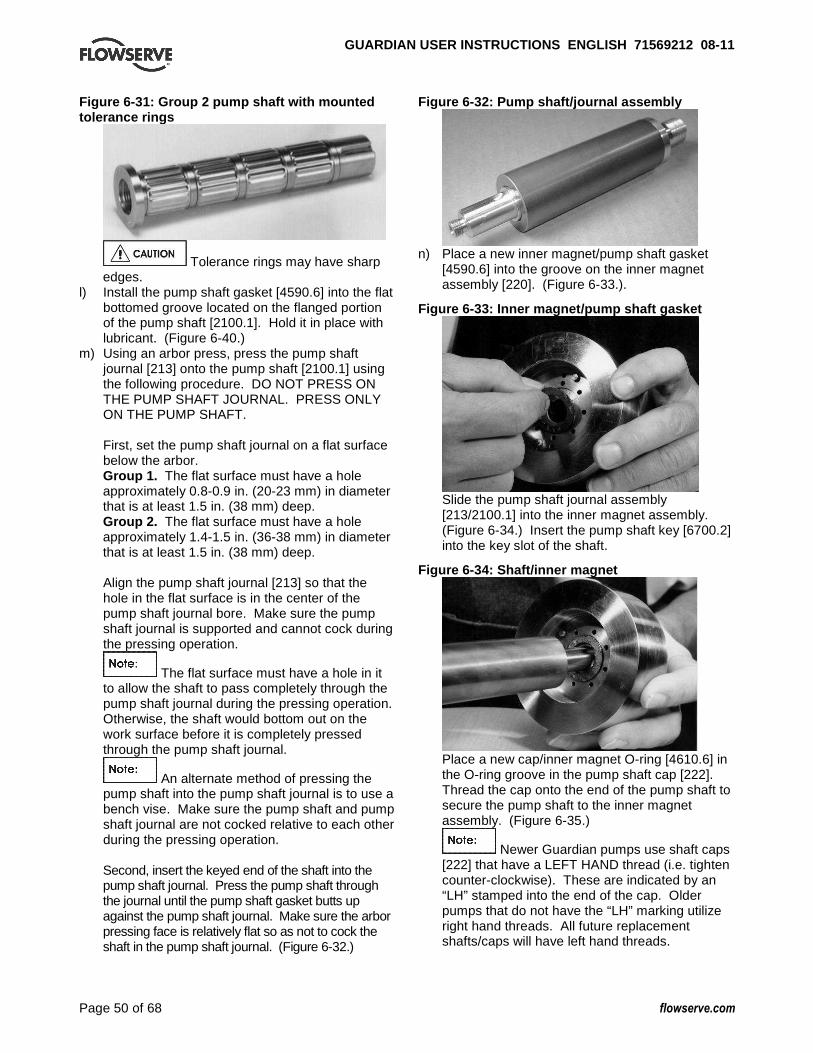
GUARDIAN USER INSTRUCTIONS ENGLISH 71569212 08-1 1
Page 50 of 68 flowserve.com
Figure 6-31: Group 2 pump shaft with mounted tolerance rings
Tolerance rings may have sharp edges.
l) Install the pump shaft gasket [4590.6] into the flat bottomed groove located on the flanged portion of the pump shaft [2100.1]. Hold it in place with lubricant. (Figure 6-40.)
m) Using an arbor press, press the pump shaft journal [213] onto the pump shaft [2100.1] using the following procedure. DO NOT PRESS ON THE PUMP SHAFT JOURNAL. PRESS ONLY ON THE PUMP SHAFT. First, set the pump shaft journal on a flat surface below the arbor. Group 1. The flat surface must have a hole approximately 0.8-0.9 in. (20-23 mm) in diameter that is at least 1.5 in. (38 mm) deep. Group 2. The flat surface must have a hole approximately 1.4-1.5 in. (36-38 mm) in diameter that is at least 1.5 in. (38 mm) deep. Align the pump shaft journal [213] so that the hole in the flat surface is in the center of the pump shaft journal bore. Make sure the pump shaft journal is supported and cannot cock during the pressing operation.
The flat surface must have a hole in it to allow the shaft to pass completely through the pump shaft journal during the pressing operation. Otherwise, the shaft would bottom out on the work surface before it is completely pressed through the pump shaft journal.
An alternate method of pressing the pump shaft into the pump shaft journal is to use a bench vise. Make sure the pump shaft and pump shaft journal are not cocked relative to each other during the pressing operation. Second, insert the keyed end of the shaft into the pump shaft journal. Press the pump shaft through the journal until the pump shaft gasket butts up against the pump shaft journal. Make sure the arbor pressing face is relatively flat so as not to cock the shaft in the pump shaft journal. (Figure 6-32.)
Figure 6-32: Pump shaft/journal assembly
n) Place a new inner magnet/pump shaft gasket
[4590.6] into the groove on the inner magnet assembly [220]. (Figure 6-33.).
Figure 6-33: Inner magnet/pump shaft gasket
Slide the pump shaft journal assembly [213/2100.1] into the inner magnet assembly. (Figure 6-34.) Insert the pump shaft key [6700.2] into the key slot of the shaft.
Figure 6-34: Shaft/inner magnet
Place a new cap/inner magnet O-ring [4610.6] in the O-ring groove in the pump shaft cap [222]. Thread the cap onto the end of the pump shaft to secure the pump shaft to the inner magnet assembly. (Figure 6-35.)
Newer Guardian pumps use shaft caps [222] that have a LEFT HAND thread (i.e. tighten counter-clockwise). These are indicated by an “LH” stamped into the end of the cap. Older pumps that do not have the “LH” marking utilize right hand threads. All future replacement shafts/caps will have left hand threads.

GUARDIAN USER INSTRUCTIONS ENGLISH 71569212 08-1 1
Page 51 of 68 flowserve.com
Figure 6-35: Shaft cap
Group 1. To tighten the pump shaft cap, place one wrench on the flats on the back of the inner magnet and use a torque wrench on the pump shaft cap. Group 2 (JG/JH-MG/MH couplings). To tighten the pump shaft cap, place one wrench on the flats on the back of the inner magnet and use a torque wrench on the pump shaft cap. Group 2 (NG/NH-QG/QH couplings). To tighten the pump shaft cap, place an adjustable spanner wrench in the two 5 mm (3/16 in.) diameter holes on the back of the magnet and use a torque wrench on the pump shaft cap.
o) Slide the pump shaft/inner magnet assembly through the bushings CAREFULLY and SLOWLY. (Figure 6-36.)
Figure 6-36 Inner magnet/shaft assembly installation
Group 1. Temporarily place shims [3126.2] on the impeller side of the thrust collar [3610]. (Figure 6-37.) Shims are used to adjust the impeller clearance. Adjustment will be completed in Section 6.9.4. Group 2. On Group 2 pumps, the shims are sandwiched between the thrust collar [3610] and thrust collar ring [207]. Place the shims into the counterbore on the thrust collar ring [207] and hold them in place with lubricant. (Figure 6-38.) Place the assembly into the thrust collar. (Figure 6-39.)
Figure 6-37: Group 1 thrust collar with shims
Figure 6-38: Group 2 Thrust Ring with Shims
Make sure the shims sit flat against the flat surface in the collar ring for Group 2. If they do not sit flat, the impeller may deform them during the next assembly step.
Figure 6-39 Group 2 Thrust collar/ring
p) Install the inboard thrust journal [211] into the
thrust collar [3610] (using an appropriate lubricant to hold it in place). (Figure 6-40.) Place the thrust collar into the bearing holder [3830] so the thrust journal sits flat on the grooved portion of the T-shaped bushing [212]. (Figure 6-41.)
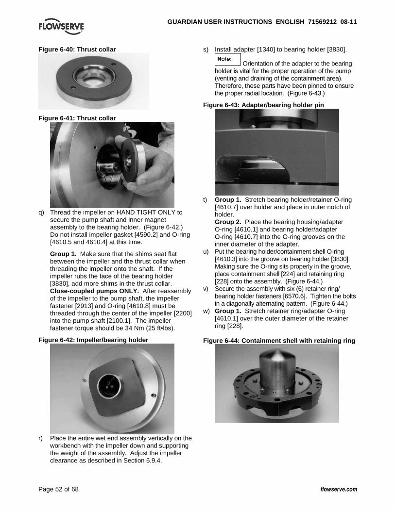
GUARDIAN USER INSTRUCTIONS ENGLISH 71569212 08-1 1
Page 52 of 68 flowserve.com
Figure 6-40: Thrust collar
Figure 6-41: Thrust collar
q) Thread the impeller on HAND TIGHT ONLY to
secure the pump shaft and inner magnet assembly to the bearing holder. (Figure 6-42.) Do not install impeller gasket [4590.2] and O-ring [4610.5 and 4610.4] at this time.
Group 1. Make sure that the shims seat flat between the impeller and the thrust collar when threading the impeller onto the shaft. If the impeller rubs the face of the bearing holder [3830], add more shims in the thrust collar. Close-coupled pumps ONLY. After reassembly of the impeller to the pump shaft, the impeller fastener [2913] and O-ring [4610.8] must be threaded through the center of the impeller [2200] into the pump shaft [2100.1]. The impeller fastener torque should be 34 Nm (25 ft•lbs).
Figure 6-42: Impeller/bearing holder
r) Place the entire wet end assembly vertically on the
workbench with the impeller down and supporting the weight of the assembly. Adjust the impeller clearance as described in Section 6.9.4.
s) Install adapter [1340] to bearing holder [3830].
Orientation of the adapter to the bearing holder is vital for the proper operation of the pump (venting and draining of the containment area). Therefore, these parts have been pinned to ensure the proper radial location. (Figure 6-43.)
Figure 6-43: Adapter/bearing holder pin
t) Group 1. Stretch bearing holder/retainer O-ring
[4610.7] over holder and place in outer notch of holder. Group 2. Place the bearing housing/adapter O-ring [4610.1] and bearing holder/adapter O-ring [4610.7] into the O-ring grooves on the inner diameter of the adapter.
u) Put the bearing holder/containment shell O-ring [4610.3] into the groove on bearing holder [3830]. Making sure the O-ring sits properly in the groove, place containment shell [224] and retaining ring [228] onto the assembly. (Figure 6-44.)
v) Secure the assembly with six (6) retainer ring/ bearing holder fasteners [6570.6]. Tighten the bolts in a diagonally alternating pattern. (Figure 6-44.)
w) Group 1. Stretch retainer ring/adapter O-ring [4610.1] over the outer diameter of the retainer ring [228].
Figure 6-44: Containment shell with retaining ring

GUARDIAN USER INSTRUCTIONS ENGLISH 71569212 08-1 1
Page 53 of 68 flowserve.com
6.9.3 Mounting the wet end to the power end 6.9.3.1 Long-coupled Guardian G & H series
pumps
Keep your fingers away from the pinch point where the bearing housing and adapter meet as the jackbolts are threaded. The magnetic forces draw the power end and wet end together with great force. a) This step must be performed with the wet end
assembly and bearing housing in the horizontal position. Thread the square head jackbolts [6575] completely through the threaded holes in the bearing housing [3200]. (The entire length of the bolts must be threaded through the holes.) Slide the wet end assembly into the bearing housing until the jackbolts slide into the recesses in the adapter [1340].
b) Turn the jackbolts [6575] counterclockwise to allow the wet end of the pump to slide into the power end. Turn the bolts one to two turns in a diagonally alternating pattern to prevent binding. This procedure ensures that the wet end is inserted evenly without damaging the magnets or the containment shell. (Figure 6-45.)
Figure 6-45: Power End/Wet End Assembly
c) Back out the jackbolts until the adapter butts up to
the bearing housing [3200]. Make sure that the adapter [1340] and the bearing housing sit flat against one another. Insert the four (4) bearing housing/adapter fasteners [6570.5] and tighten them in an alternating pattern. Make sure the jackbolts do not interfere with the tightening of these bolts.
6.9.3.2 Close-coupled Guardian G & H series
pumps – lantern assembly to the wet end
a) Make sure the lantern/retainer o-ring [4610.1] is in place in the wet end.
b) Orient the wet end vertically on the work surface. (Figure 6-46.) Align the lantern [3132] such that the roll pin in the adapter [1340] is aligned with the mating hole in the lantern [3132]. Place the lantern into adapter making sure the lantern seats flat on the adapter. Insert the four (4) lantern/adapter fasteners [6570.5] and tighten in an alternating pattern.
c) The wet end assembly can now be assembled to the outer magnet/motor assembly.
Figure 6-46: Lantern assembly to wet end
6.9.3.3 Close-coupled Guardian G & H series
pumps – drive end to the wet end assembly
Keep your fingers away from the pinch point where the lantern [3132] and motor flange [251] meet as the jackscrews are threaded. Magnetic forces draw the drive end and wet end together with great force. a) This step must be performed with the wet end
assembly and motor assembly in the horizontal position. Thread the square head jackscrews [6575] completely through the threaded holes in the lantern [3132]. The entire length of the jackscrews must be threaded through the holes.
b) Install a lantern gasket [4590.7] on the face of the motor flange [251].
c) Slide the motor assembly toward the wet end assembly until the jackscrews slide into the recess in the motor flange. (See Figure 6-47.)
Figure 6-47: Motor/pump assembly

GUARDIAN USER INSTRUCTIONS ENGLISH 71569212 08-1 1
Page 54 of 68 flowserve.com
d) Turn the jackscrews [6575] counterclockwise to allow the outer magnet/motor assembly to slide over the containment shell [224]. Turn the screws one to two turns in an alternating pattern to prevent binding.
e) Back out jackscrews until the lantern [3132] butts up to the motor flange [251]. Make sure that the lantern and motor flange sit flat against one another. Insert the four (4) motor flange/lantern fasteners [6570.10] and tighten them in an alternating pattern. Make sure the jackscrews [6575] do not interfere with the tightening of these bolts.
6.9.4 Adjusting the Impeller a) Temporarily tighten the impeller [2200] to the
pump shaft [2100.1]. Turn the impeller in a clockwise direction until the impeller is firmly seated but only hand tight.
Do not attempt to tighten the impeller on the shaft by hitting the impeller with a hammer or by inserting a pry bar between the impeller vanes. Serious damage to the impeller may result from these actions.
b) Place the entire assembly vertically on the workbench with the impeller down and supporting the weight of the assembly. Measure the minimum clearance between the bearing holder face [3830] and the impeller [2200] with a feeler gauge without forcing the impeller away from the face. Measure the clearance between the bearing holder and ALL THE VANES to determine closest vane. Use the smallest measurement as your guide and record this number.
c) The Guardian Magnetic Drive requires a clearance of 0.45 mm (0.018 in.) ± 0.08 mm (0.003 in.), regardless of operating temperature, between the closest impeller vane and the face of the bearing holder. Determine the number of shims that must be placed between the impeller and the thrust collar by subtracting the minimum clearance between the bearing holder and the impeller from the thickness of the impeller shims already inserted. Add 0.45 mm (0.018 in.) to this difference. This number is the thickness of shims that are required to adjust the impeller. For example, if the initial measurement between the closest impeller vane and the bearing holder face is 0.75 mm (0.030 in.), and the thickness of the shims already inserted is 1.00 mm (0.040 in.), subtract 0.75 mm (0.030 in.) from 1.00 mm (0.040 in.). 1.00 mm – 0.75 mm = 0.25 mm (0.040 in. – 0.030 in. = 0.010 in.)
Next, add 0.45 mm (0.018 in.) to 0.25 mm (0.010 in.) to determine the thickness of the shims required to adjust the impeller properly. 0.25 mm + 0.45 mm = 0.70 mm (0.010 in. + 0.018 in. = 0.028 in.) A combination of shims equal to 0.70 mm (0.028 in.) thickness would then be required to set the impeller properly.
d) Set the assembly back to horizontal. Remove the impeller and the 1.00 mm (0.040 in.) combination of shims from the pump shaft. Removal should only require using your hands since the impeller was only hand tightened. If necessary, use the Durco impeller wrench to hold the shaft stationary.
e) Place the required number of shims against the shoulder in the thrust collar [3610] or thrust collar ring [207]. Thread the impeller back onto the pump shaft and tighten as described in step a). Make sure the shims sit flat between mating faces.
f) Recheck the impeller clearance as described in step b). If the distance is more or less than required, repeat steps c) thru f) until clearance is correct.
g) When the clearance is properly set, set the assembly back to horizontal. Remove the impeller and thrust collar [3610]. Group 1. Place the thrust collar/pump shaft O-ring [4610.4] in the groove on the back side of the thrust collar. Stretch the thrust collar ring/ O-ring [4610.5] over the hub on the backside of the impeller. Group 2. Remove the thrust collar ring and shims from the thrust collar. Place the thrust collar/ring O-ring [4610.5] into the O-ring groove on the shimming side of the thrust collar. Using an arbor press, press the thrust collar ring and shims into the thrust collar. In order to keep the shims from falling out of the thrust collar during this press, the ring should be placed on the work surface with the thrust collar on top of it. Place the thrust collar/pump shaft O-ring [4610.4] into the groove on the pump shaft side of the thrust collar. Place the thrust collar into the bearing holder [3830] so the thrust journal sits flat on the grooved portion of the T-shaped bushing [212].
h) Install new impeller gasket [4590.2] and tighten the impeller until it is firmly seated.
Failure to tighten the impeller sufficiently may allow liquid to reach the impeller thread. Additionally, a loose impeller will be tightened when the pump is started, but may be very difficult to remove later.

GUARDIAN USER INSTRUCTIONS ENGLISH 71569212 08-1 1
Page 55 of 68 flowserve.com
The impeller will be difficult to turn because there is deformation of the O-rings during seating of the impeller.
6.9.5 Mounting the drive assembly to the casing
a) Before mounting the drive assembly to the pump casing, drive the studs [6572] into the appropriate tapped holes. Place a new bearing holder/casing gasket [4590.1] on the gasket face of the bearing holder.
b) Move the drive assembly into position in front of the casing. Slide the drive assembly into the
casing and thread the eight (8) casing fastener nuts [6580] onto the casing/adapter fasteners [6572]. Torque these bolts in an alternating pattern.
c) If the pump flange(s) have tapped holes, select flange fasteners with thread engagement at least equal to the fastener diameter but that do not bottom out in the tapped holes before the joint is tight.
d) Secure the bearing housing foot with appropriate fastener(s).

GUARDIAN USER INSTRUCTIONS ENGLISH 71569212 08-1 1
Page 56 of 68 flowserve.com
7 FAULTS; CAUSES AND REMEDIES The following is a guide to troubleshooting problems with Flowserve Guardian G & H series pumps. Common problems are analyzed and solutions offered. Obviously, it is impossible to cover every possible scenario. If a problem exists that is not covered by one of the examples then refer to one of the books listed in section 10, Additional sources of information or contact a Flowserve sales engineer or distributor/representative for assistance.
FAULT SYMPTOM Pump not reaching design flow rate
⇓⇓⇓⇓⇓⇓⇓⇓ Pump not reaching design head (TDH)
⇓⇓⇓⇓⇓⇓⇓⇓ No discharge or flow with pump running
⇓⇓⇓⇓⇓⇓⇓⇓ Pump operates for short period, then loses prime
⇓⇓⇓⇓⇓⇓⇓⇓ Excessive noise from wet end
⇓⇓⇓⇓⇓⇓⇓⇓ Excessive noise from power end
⇓⇓⇓⇓⇓⇓⇓⇓ Pump exhibits increased or higher than anticipated power consumption
⇓⇓⇓⇓⇓⇓⇓⇓ Pump exhibits decreased or lower than anticipated power consumption
⇓⇓⇓⇓⇓⇓⇓⇓
⇓⇓⇓⇓⇓⇓⇓⇓
⇓⇓⇓⇓⇓⇓⇓⇓ POSSIBLE CAUSES POSSIBLE REMEDIES
���� ���� ���� ���� Insufficient NPSH. (Noise may not be present.)
Recalculate NPSH available. It must be greater than the NPSH required by pump at desired flow. If not, redesign suction piping, holding number of elbows and number of planes to a minimum to avoid adverse flow rotation as it approaches the impeller.
���� ���� ���� ���� System head greater than anticipated. Reduce system head by increasing pipe size and/or reducing number of fittings. Increase impeller diameter. (note: Increasing impeller diameter may require use of a larger motor.)
���� ���� ���� Entrained air. Air leak from atmosphere on suction side.
1. Check suction line gaskets and threads for tightness. 2. If vortex formation is observed in suction tank, install vortex
breaker. 3. Check for minimum submergence
���� ���� Entrained gas from process. Process generated gases may require larger pumps. ���� ���� ���� Speed too low. Check motor speed against design speed.
���� ���� ���� Direction of rotation wrong. After confirming wrong rotation, reverse any two of three leads on a three phase motor. The pump should be disassembled and inspected before it is restarted.
���� ���� ���� Impeller too small. Replace with proper diameter impeller. (NOTE: Increasing impeller diameter may require use of a larger motor.)
���� ���� ���� Impeller clearance too large. Reset impeller clearance.
���� ���� ���� Plugged impeller, suction line or casing which may be due to a product or large solids.
1. Reduce length of fiber when possible. 2. Reduce solids in the process fluid when possible. 3. Consider larger pump.
���� ���� ���� Wet end parts (casing cover, impeller) worn, corroded or missing. Replace part or parts.
���� ���� ���� Not properly primed. Repeat priming operation, recheck instructions. If pump has run dry, disassemble and inspect the pump before operation.
���� ���� Impeller rubbing. 1. Check and reset impeller clearance. 2. Check outboard bearing assembly for axial end play.
���� ���� ���� Damaged bushings, pump shaft, thrust journals, or impeller. Replace damaged parts.
���� Abnormal fluid rotation due to complex suction piping.
Redesign suction piping, holding the number of elbows and planes to a minimum to avoid adverse fluid rotation as it approaches the impeller.
���� ���� ���� Magnetic coupling decoupled due to excessive temperature or excessive horsepower requirements.
1. Check process temperature to verify it’s within operating limits of pump. 2. Check horsepower required by the process to verify it is within the operating limits of the coupling size. 3. Replacement of the magnet assemblies may be necessary if the magnets overheated and were permanently damaged. A static torque test of the magnetic coupling may be necessary. Contact your Flowserve representative for details.
���� ���� Inner magnet rubbing bearing holder. Check for damaged or worn pump shaft and bushings.

GUARDIAN USER INSTRUCTIONS ENGLISH 71569212 08-1 1
Page 57 of 68 flowserve.com
Pump not reaching design flow rate
⇓⇓⇓⇓⇓⇓⇓⇓ Pump not reaching design head (TDH)
⇓⇓⇓⇓⇓⇓⇓⇓ No discharge or flow with pump running
⇓⇓⇓⇓⇓⇓⇓⇓ Pump operates for short period, then loses prime
⇓⇓⇓⇓⇓⇓⇓⇓ Excessive noise from wet end
⇓⇓⇓⇓⇓⇓⇓⇓ Excessive noise from power end
⇓⇓⇓⇓⇓⇓⇓⇓ Pump exhibits increased or higher than anticipated power consumption
⇓⇓⇓⇓⇓⇓⇓⇓ Pump exhibits decreased or lower than anticipated power consumption
⇓⇓⇓⇓⇓⇓⇓⇓
⇓⇓⇓⇓⇓⇓⇓⇓
⇓⇓⇓⇓⇓⇓⇓⇓ POSSIBLE CAUSES POSSIBLE REMEDIES
���� ����
Bearing contamination appearing on the raceways as scoring, pitting, scratching or rusting caused by adverse environment and entrance of abrasive contaminants from atmosphere.
1. Work with clean tools in clean surroundings. 2. Remove all outside dirt from housing before exposing bearings. 3. Handle with clean dry hands. 4. Treat a used bearing as carefully as a new one. 5. Use clean solvent and flushing oil. 6. Protect disassembled bearing from dirt and moisture. 7. Keep bearings wrapped in paper or clean cloth while not in use. 8. Clean inside of housing before replacing bearings. 9. Check oil seals and replace as required. 10. Check all plugs and tapped openings to make sure that they are tight.
���� ����
Brinelling of bearing identified by indentation on the ball races, usually caused by incorrectly applied forces in assembling the bearing or by shock loading such as hitting the bearing or drive shaft with a hammer.
When mounting the bearing on the drive shaft use a proper size ring and apply the pressure against the inner ring only. Be sure when mounting a bearing to apply the mounting pressure slowly and evenly.
���� ����
False brinelling of bearing identified again by either axial or circumferential indentations usually caused by vibration of the balls between the races in a stationary bearing.
1. Correct the source of vibration. 2. Where bearings are oil lubricated and employed in units that may be out of service for extended periods, the drive shaft should be turned over periodically to relubricate all bearing surfaces at intervals of one to three months.
���� ����
Thrust overload on bearing identified by flaking ball path on one side of the outer race or in the case of maximum capacity bearings, may appear as a spalling of the races in the vicinity of the loading slot. (Please note: maximum capacity bearings are not recommended in Mark 2I pumps.) These thrust failures are caused by improper mounting of the bearing or excessive thrust loads.
Follow correct mounting procedures for bearings.
���� ����
Misalignment identified by fracture of ball retainer or a wide ball path on the inner race and a narrower cocked ball path on the outer race. Misalignment is caused by poor mounting practices or defective drive shaft. For example, bearing not square with the centerline or possibly a bent shaft due to improper handling.
Handle parts carefully and follow recommended mounting procedures. Check all parts for proper fit and alignment.
���� ����
Bearing damaged by electric arcing identified as electro- etching of both inner and outer ring as a pitting or cratering. Electrical arcing is caused by a static electrical charge emanating from belt drives, electrical leakage or short circuiting.
1. Where current shunting through the bearing cannot be corrected, a shunt in the form of a slip ring assembly should be incorporated. 2. Check all wiring, insulation and rotor windings to be sure that they are sound and all connections are properly made. 3. Where pumps are belt driven, consider the elimination of static charges by proper grounding or consider belt material that is less generative.
���� ����
Bearing damage due to improper lubrication, identified by one or more of the following: 1. Abnormal bearing temperature
1. Be sure the lubricant is clean. 2. Be sure proper amount of lubricant is used. The constant level oiler supplied with Durco pumps will maintain the proper oil level if it is installed and operating properly. In the case of greased

GUARDIAN USER INSTRUCTIONS ENGLISH 71569212 08-1 1
Page 58 of 68 flowserve.com
Pump not reaching design flow rate
⇓⇓⇓⇓⇓⇓⇓⇓ Pump not reaching design head (TDH)
⇓⇓⇓⇓⇓⇓⇓⇓ No discharge or flow with pump running
⇓⇓⇓⇓⇓⇓⇓⇓ Pump operates for short period, then loses prime
⇓⇓⇓⇓⇓⇓⇓⇓ Excessive noise from wet end
⇓⇓⇓⇓⇓⇓⇓⇓ Excessive noise from power end
⇓⇓⇓⇓⇓⇓⇓⇓ Pump exhibits increased or higher than anticipated power consumption
⇓⇓⇓⇓⇓⇓⇓⇓ Pump exhibits decreased or lower than anticipated power consumption
⇓⇓⇓⇓⇓⇓⇓⇓
⇓⇓⇓⇓⇓⇓⇓⇓
⇓⇓⇓⇓⇓⇓⇓⇓ POSSIBLE CAUSES POSSIBLE REMEDIES rise. 2. A stiff cracked grease appearance. 3. A brown or bluish discoloration of the bearing races.
lubricated bearings, be sure that there is space adjacent to the bearing into which it can rid itself of excessive lubricant, otherwise the bearing may overheat and fail prematurely. 3. Be sure the proper grade of lubricant is used.
���� ���� Outer magnet assembly rubbing bearing housing.
1. Check integrity of ball bearings. 2. Make sure drive shaft is not bent. 3. Make sure outer magnet assembly has not come unscrewed due to incorrect motor rotation.

GUARDIAN USER INSTRUCTIONS ENGLISH 71569212 08-1 1
Page 59 of 68 flowserve.com
8 PARTS LIST AND DRAWINGS 8.1 Cutaway – Guardian G & H Series – Group 1 – lon g coupled
2100
.1
3830
6570
.6
1340
4610
.1
4610
.724
145
90.6
230A
6570
.922
023
067
00.2
4610
.622
223
165
2143
10.1
3260
4610
.9
6570
.8
4310
.2
6700
2100
.2
3011
3013
6570
.3
6569
.4
6569
.5
3856
3855
4260
3132
3126
.165
70.4
3134
6570
.729
2321
765
7565
70.5
6580
.1
6570
.124
022
845
90.1
224
4610
.3
216
212
213
3126
.2
4590
.2
4610
.4
1100
4610
.5
4590
.6
3610
2200
211

GUARDIAN USER INSTRUCTIONS ENGLISH 71569212 08-1 1
Page 60 of 68 flowserve.com
8.1.1 Parts list – Guardian G & H Series – Group 1 – long coupled
Des
crip
tion
O-r
ing
O-r
ing
O-r
ing
O-r
ing
O-r
ing
Ven
t Plu
g
Plu
g
Plu
g
Scr
ew
Scr
ew
Scr
ew
Scr
ew
Scr
ew
Scr
ew
Scr
ew
Stu
d
Jack
scre
w
Nut
Key
Key
Qty
1 1 1 1 1 1 1 1 3 1 4 6 4 1 4 8 4 8 1 1
Item
4610
.4
4610
.5
4610
.6
4610
.7
4610
.9
6521
6569
.1
6569
.5
6570
.3
6570
.4
6570
.5
6570
.6
6570
.7
6570
.8
6570
.9
6572
.1
6575
6580
.1
6700
.1
6700
.2
Des
crip
tion
Pin
Bal
l Bea
ring
Bal
l Bea
ring
Shi
m
Shi
m
Sup
port
Foo
t
Bea
ring
Hou
sing
Bea
ring
Cov
er
Thr
ust C
olla
r
Hol
der
Con
stan
t Lev
el O
iler
Sig
ht O
il G
auge
Spr
ing
Lip
Sea
l
Lip
Sea
l
Gas
ket
Gas
ket
Gas
ket
O-r
ing
O-r
ing
Qty
8 1 1 n/a
n/a
1 1 1 1 1 1 1 1 1 1 1 1 2 1 1
Item
2923
3011
3013
3126
.1
3126
.2
3134
3200
3260
3610
3830
3855
3856
4260
4310
.1
4310
.2
4590
.1
4590
.2
4590
.6
4610
.1
4610
.3
Des
crip
tion
Tag
– O
il Le
vel
Jour
nal –
Inbo
ard
Bus
hing
– In
boar
d
Jour
nal –
Sle
eve
Bus
hing
– O
utbo
ard
Jour
nal –
Out
boar
d
Mag
net A
ssy
– In
ner
Cap
– P
ump
Sha
ft
Con
tain
men
t She
ll
Ret
aine
r R
ing
Mag
net A
ssy
– O
uter
Rub
Pad
Fla
nge
– O
uter
Mag
net
Sup
port
– H
ousi
ng
Tol
eran
ce R
ing
Cas
ing
Ada
pter
Sha
ft
Sha
ft
Impe
ller
Qty
1 1 1 1 1 1 1 1 1 1 1 4 1 1 2 1 1 1 1 1
Par
ts li
st –
Gua
rdia
n G
& H
Ser
ies
– G
roup
1 –
long
cou
pled
Item
200B
211
212
213
216
217
220
222
224
228
230
230A
231
240
241
1100
1340
2100
.1
2100
.2
2200
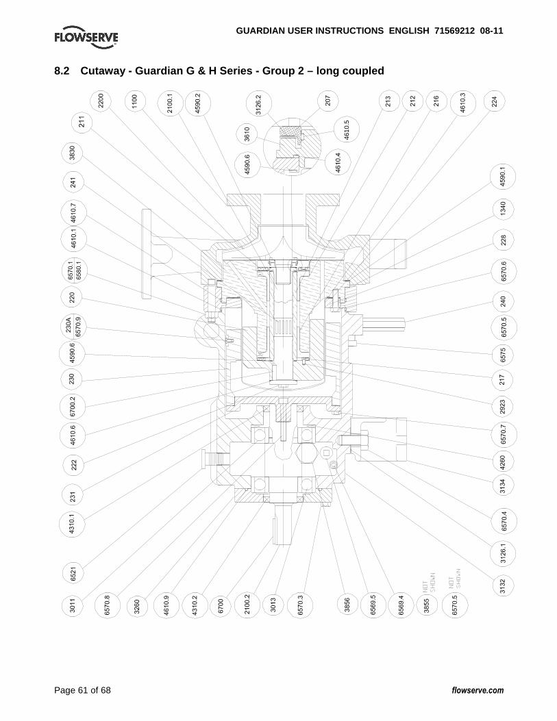
GUARDIAN USER INSTRUCTIONS ENGLISH 71569212 08-1 1
Page 61 of 68 flowserve.com
8.2 Cutaway - Guardian G & H Series - Group 2 – lon g coupled
4610
.5
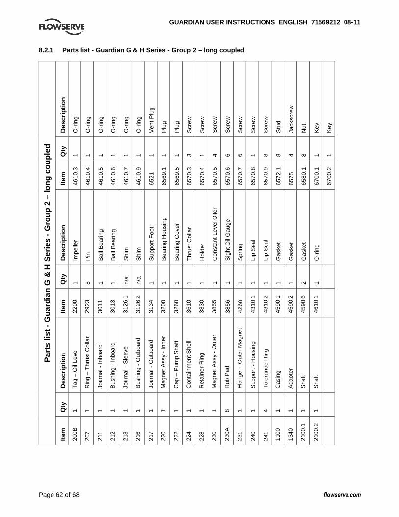
GUARDIAN USER INSTRUCTIONS ENGLISH 71569212 08-1 1
Page 62 of 68 flowserve.com
8.2.1 Parts list - Guardian G & H Series - Group 2 – long coupled
Des
crip
tion
O-r
ing
O-r
ing
O-r
ing
O-r
ing
O-r
ing
O-r
ing
Ven
t Plu
g
Plu
g
Plu
g
Scr
ew
Scr
ew
Scr
ew
Scr
ew
Scr
ew
Scr
ew
Scr
ew
Stu
d
Jack
scre
w
Nut
Key
Key
Qty
1 1 1 1 1 1 1 1 1 3 1 4 6 6 1 8 8 4 8 1 1
Item
4610
.3
4610
.4
4610
.5
4610
.6
4610
.7
4610
.9
6521
6569
.1
6569
.5
6570
.3
6570
.4
6570
.5
6570
.6
6570
.7
6570
.8
6570
.9
6572
.1
6575
6580
.1
6700
.1
6700
.2
Des
crip
tion
Impe
ller
Pin
Bal
l Bea
ring
Bal
l Bea
ring
Shi
m
Shi
m
Sup
port
Foo
t
Bea
ring
Hou
sing
Bea
ring
Cov
er
Thr
ust C
olla
r
Hol
der
Con
stan
t Lev
el O
iler
Sig
ht O
il G
auge
Spr
ing
Lip
Sea
l
Lip
Sea
l
Gas
ket
Gas
ket
Gas
ket
O-r
ing
Qty
1 8 1 1 n/a
n/a
1 1 1 1 1 1 1 1 1 1 1 1 2 1
Item
2200
2923
3011
3013
3126
.1
3126
.2
3134
3200
3260
3610
3830
3855
3856
4260
4310
.1
4310
.2
4590
.1
4590
.2
4590
.6
4610
.1
Des
crip
tion
Tag
– O
il Le
vel
Rin
g –
Thr
ust C
olla
r
Jour
nal -
Inbo
ard
Bus
hing
- In
boar
d
Jour
nal -
Sle
eve
Bus
hing
- O
utbo
ard
Jour
nal -
Out
boar
d
Mag
net A
ssy
- In
ner
Cap
– P
ump
Sha
ft
Con
tain
men
t She
ll
Ret
aine
r R
ing
Mag
net A
ssy
- O
uter
Rub
Pad
Fla
nge
– O
uter
Mag
net
Sup
port
- H
ousi
ng
Tol
eran
ce R
ing
Cas
ing
Ada
pter
Sha
ft
Sha
ft
Qty
1 1 1 1 1 1 1 1 1 1 1 1 8 1 1 4 1 1 1 1
Par
ts li
st -
Gua
rdia
n G
& H
Ser
ies
- G
roup
2 –
long
cou
pled
Item
200B
207
211
212
213
216
217
220
222
224
228
230
230A
231
240
241
1100
1340
2100
.1
2100
.2

GUARDIAN USER INSTRUCTIONS ENGLISH 71569212 08-1 1
Page 63 of 68 flowserve.com
8.3 Cutaway - Guardian G & H Series - Group 1 – clo se coupled
1100
2200
4590
.2
213
212
4590
.146
10.7
228
4610
.165
70.5
216
217
2923
3132
6570
.745
90.7
231
224
222
6570
.8
4610
.6
4590
.825
122
023
045
90.6
230A
6570
.9
1340
6570
.646
10.3
3830
241
211
4610
.4
2100
.1
3126
.2
4610
.5
3610
6700
.2
6575
103B
103A
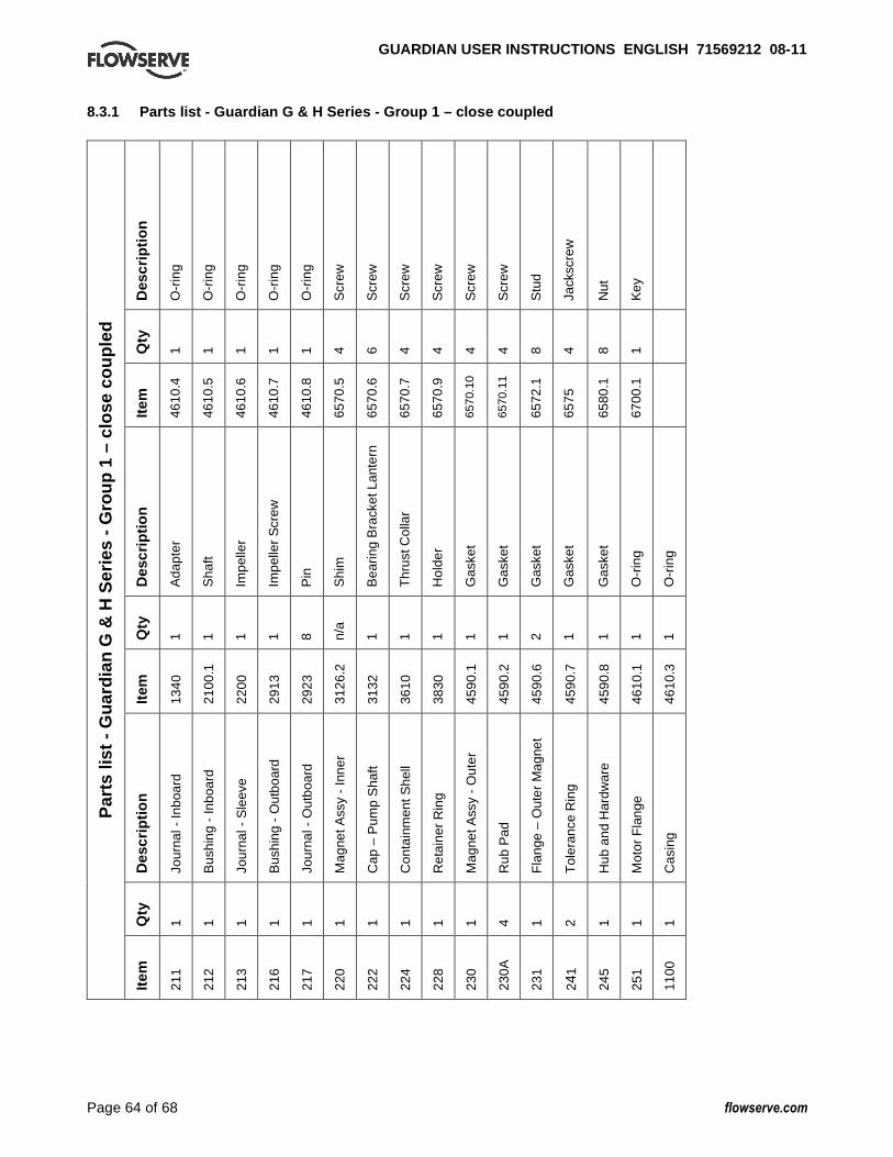
GUARDIAN USER INSTRUCTIONS ENGLISH 71569212 08-1 1
Page 64 of 68 flowserve.com
8.3.1 Parts list - Guardian G & H Series - Group 1 – close coupled
Des
crip
tion
O-r
ing
O-r
ing
O-r
ing
O-r
ing
O-r
ing
Scr
ew
Scr
ew
Scr
ew
Scr
ew
Scr
ew
Scr
ew
Stu
d
Jack
scre
w
Nut
Key
Qty
1 1 1 1 1 4 6 4 4 4 4 8 4 8 1
Item
4610
.4
4610
.5
4610
.6
4610
.7
4610
.8
6570
.5
6570
.6
6570
.7
6570
.9
6570
.10
6570
.11
6572
.1
6575
6580
.1
6700
.1
Des
crip
tion
Ada
pter
Sha
ft
Impe
ller
Impe
ller
Scr
ew
Pin
Shi
m
Bea
ring
Bra
cket
Lan
tern
Thr
ust C
olla
r
Hol
der
Gas
ket
Gas
ket
Gas
ket
Gas
ket
Gas
ket
O-r
ing
O-r
ing
Qty
1 1 1 1 8 n/a
1 1 1 1 1 2 1 1 1 1
Item
1340
2100
.1
2200
2913
2923
3126
.2
3132
3610
3830
4590
.1
4590
.2
4590
.6
4590
.7
4590
.8
4610
.1
4610
.3
Des
crip
tion
Jour
nal -
Inbo
ard
Bus
hing
- In
boar
d
Jour
nal -
Sle
eve
Bus
hing
- O
utbo
ard
Jour
nal -
Out
boar
d
Mag
net A
ssy
- In
ner
Cap
– P
ump
Sha
ft
Con
tain
men
t She
ll
Ret
aine
r R
ing
Mag
net A
ssy
- O
uter
Rub
Pad
Fla
nge
– O
uter
Mag
net
Tol
eran
ce R
ing
Hub
and
Har
dwar
e
Mot
or F
lang
e
Cas
ing
Qty
1 1 1 1 1 1 1 1 1 1 4 1 2 1 1 1
Par
ts li
st -
Gua
rdia
n G
& H
Ser
ies
- G
roup
1 –
clo
se
coup
led
Item
211
212
213
216
217
220
222
224
228
230
230A
231
241
245
251
1100
GUARDIAN USER INSTRUCTIONS ENGLISH 71569212 08-1 1
Page 65 of 68 flowserve.com
9 CERTIFICATION Certificates, determined from the contract requirements are provided with these instructions where applicable. Examples are certificates for CE marking and ATEX marking etc. If required, copies of other certificates sent separately to the Purchaser should be obtained from Purchaser for retention with these User Instructions. 10 OTHER RELEVANT
DOCUMENTATION AND MANUALS 10.1 Supplementary User Instructions Supplementary instructions such as for a driver, instrumentation, controller, seals, sealant systems etc are provided as separate documents in their original format. If further copies of these are required they should be obtained from the supplier for retention with these User Instructions. 10.2 Change notes If any changes, agreed with Flowserve Pump Division, are made to the product after it is supplied, a record of the details should be maintained with these User Instructions. 10.3 Additional sources of information The following are excellent sources for additional information on Flowserve Mark 3 pumps, and centrifugal pumps in general. Pump Engineering Manual R.E. Syska, J.R. Birk, Flowserve Corporation, Dayton, Ohio, 1980. Specification for Horizontal End Suction Centrifugal Pumps for Chemical Process, ASME B73.1M The American Society of Mechanical Engineers, New York, NY. Specification for Sealless Horizontal End Suction Metallic Centrifugal Pumps for Chemical Process, ASME B73.3 The American Society of Mechanical Engineers, New York, NY. American National Standard for Centrifugal Pumps for Nomenclature, Definitions, Design and Application (ANSI/HI 1.1-1.3) Hydraulic Institute, 9 Sylvan Way, Parsippany, New Jersey 07054-3802.
American National Standard for Centrifugal Pumps for Installation, Operation, and Maintenance (ANSI/HI 1.4) Hydraulic Institute, 9 Sylvan Way, Parsippany, New Jersey 07054-3802. Flowserve Durco Pump Parts Catalog. Flowserve Guardian Sales Bulletin. Flowserve Sealless Process Pump Technical Bulletin (P-20-501). RESP73H Application of ASME B73.1M-1991, Specification for Horizontal End Suction Centrifugal Pumps for Chemical Process, Process Industries Practices Construction Industry Institute, The University of Texas at Austin, 3208 Red River Street, Suite 300, Austin, Texas 78705. Pump Handbook 2nd edition, Igor J. Karassik et al, McGraw-Hill, Inc., New York, NY, 1986. Centrifugal Pump Sourcebook John W. Dufour and William E. Nelson, McGraw-Hill, Inc., New York, NY, 1993. Pumping Manual, 9th edition T.C. Dickenson, Elsevier Advanced Technology, Kidlington, United Kingdom, 1995.

GUARDIAN USER INSTRUCTIONS ENGLISH 71569212 08-1 1
Page 66 of 68 flowserve.com
NOTES:

GUARDIAN USER INSTRUCTIONS ENGLISH 71569212 08-1 1
Page 67 of 68 flowserve.com
NOTES:
GUARDIAN USER INSTRUCTIONS ENGLISH 71569212 08-1 1
Your Flowserve factory contact: Flowserve Pump Division 3900 Cook Boulevard Chesapeake, VA 23323-1626 USA Telephone +1 757 485 8000 Fax +1 757 485 8149 Flowserve GB Limited PO Box 17, Newark, Notts NG24 3EN United Kingdom Telephone (24 hours) +44 (0)1636 494 600 Sales & Admin Fax +44 (0)1636 705 991 Repair & Service Fax +44 (0)1636 494 833 E-mail [email protected]
Your local Flowserve representative: To find your local Flowserve representative please use the Sales Support Locator System found at www.flowserve.com
FLOWSERVE REGIONAL SALES OFFICES:
USA and Canada
Flowserve Corporation
5215 North O’Connor Blvd.,
Suite 2300
Irving, Texas 75039-5421, USA
Telephone +1 972 443 6500
Fax +1 972 443 6800
Europe, Middle East, Africa
Flowserve FSG – Italy
Worthing S.r.l.
Via Rossini 90/92
20033 Desio (Milan), Italy
Telephone +39 0362 6121
Fax +39 0362 628 882
Latin America and Caribbean
Flowserve Corporation
6840 Wynnwood Lane
Houston, Texas 77008, USA
Telephone +1 713 803 4434
Fax +1 713 803 4497
Asia Pacific
Flowserve Pte. Ltd
10 Tuas Loop
Singapore 637345
Telephone +65 6771 0600
Fax +65 6862 2329