guardpost - ness corporationnesscorporation.com/installationmanual/ness_guardpost...4 ness guardpost...
TRANSCRIPT

Wireless security system
With Gsm monitorinG
& tWo Way Voice
the World’s smartest Wireless intruder alarm system
Guardpost
installation & Programming manual
rev 1.2

all rights reserved. no part of this publication may be reproduced, transmitted or stored in a retrieval system in any form or by any means, electronic, mechanical, photocopying, recording, or otherwise, without the prior written permission of ness.
ness reserves the right to make changes to features and specifications at any time without prior notification in the interest of ongoing product development and improvement.
© 2012 ness corporation Pty ltd aBn 28 069 984 372
NSW Ph 02 8825 9222 VIC Ph 03 9875 6400 QLD Ph 07 3399 4910 WA Ph 08 9328 2511 SA Ph 08 8152 [email protected] [email protected] [email protected] [email protected] [email protected]
innovative electronic solutions www.ness.com.au
WArNINgS & NotICeSness corporation manufacturing processes are accredited to iso9001 quality standards and all possible care and diligence has been applied during manufacture to ensure the reliable operation of this product. however there are various external factors that may impede or restrict the operation of this product in accordance with the product’s specification.these factors include, but are not limited to:1. erratic or reduced radio range (if radio accessories are installed). ness radio products are sophisticated low power devices, however
the presence of in-band radio signals, high power transmissions or interference caused by electrical appliances such as mains inverters, Wireless routers, cordless Phones, computers, tVs and other electronic devices may reduce radio range performance. While such occurrences are unusual, they are possible. in this case it may be necessary to either increase the physical separation between the ness receiver and other devices or if possible change the radio frequency or channel of the other devices.
2. unauthorised tampering, physical damage, electrical interruptions such as mains failure, electrical spikes or lightning.3. solar power inverters are a known source of electrical interference. Please ensure that this product and all associated cabling is
installed at least 3 metres away from a solar power inverter and its cabling.WArNINg: installation and maintenance to be performed only by qualified service personnel.CAUtIoN: risk of explosion if battery is replaced by an incorrect type. dispose of used batteries in accordance with local regulations.
Guardpost installation & Programming manualrev1.2 may 2012
document Part no: 890-337
this document is for use with Guardpost / securityGuard iii models shown. Features and options not supported by some models can be ignored during programming and operation.
rad
io F
rreq
uenc
y
Lang
uag
e
rad
io K
eys
Sup
plie
d
List
en-i
n D
ialle
r
SM
S S
end
SM
S r
ecei
ve
rad
io S
iren
sup
po
rt
So
lar
Ch
arg
ing
sup
po
rt
Nes
s S
IM C
ard
sup
plie
d
two
Way
Vo
ice
Aud
ible
Mo
nito
ring
100-275 securityguard iii Gsm c-Protocol 304mhz english rK3 8 4 4 4 4 8 8 8100-281 securityguard iii Gsm n-Protocol 304mhz english rK3 8 4 4 4 4 8 8 8106-285 ness Guardpost tWV no sim 304mhz english rK4 4 4 4 4 4 8 4 4106-286 ness Guardpost tWV with sim 304mhz english rK4 4 4 4 4 4 4 4 4100-279 securityguard iii Gsm europe 868mhz english rK4 4 4 4 4 4 8 4 4101-425 securityguard iii Gsm tWV Portugal 868mhz Portugese rK4 4 4 4 4 4 8 4 4 106-298 securityguard iii Gsm tWV italy 868mhz italian rK4 4 4 4 4 4 8 4 4

Guardpost Features. . . . . . . . . . . . . . . . . . . . . . . . . . . . . . . . . . . . . . . . . . . . . . . . . . . . . . . . . . . . . . 4Compatibility . . . . . . . . . . . . . . . . . . . . . . . . . . . . . . . . . . . . . . . . . . . . . . . . . . . . . . . . . . . . . . . . . . . 4Introduction . . . . . . . . . . . . . . . . . . . . . . . . . . . . . . . . . . . . . . . . . . . . . . . . . . . . . . . . . . . . . . . . . . . . 4Product Overview . . . . . . . . . . . . . . . . . . . . . . . . . . . . . . . . . . . . . . . . . . . . . . . . . . . . . . . . . . . . . . . 5Installation . . . . . . . . . . . . . . . . . . . . . . . . . . . . . . . . . . . . . . . . . . . . . . . . . . . . . . . . . . . . . . . . . . . . . 6Wiring . . . . . . . . . . . . . . . . . . . . . . . . . . . . . . . . . . . . . . . . . . . . . . . . . . . . . . . . . . . . . . . . . . . . . . . . 6SIM Card Installation . . . . . . . . . . . . . . . . . . . . . . . . . . . . . . . . . . . . . . . . . . . . . . . . . . . . . . . . . . . . . 7Startup . . . . . . . . . . . . . . . . . . . . . . . . . . . . . . . . . . . . . . . . . . . . . . . . . . . . . . . . . . . . . . . . . . . . . . . . 8Radio Keys . . . . . . . . . . . . . . . . . . . . . . . . . . . . . . . . . . . . . . . . . . . . . . . . . . . . . . . . . . . . . . . . . . . . 8
User Operation . . . . . . . . . . . . . . . . . . . . . . . . . . . . . . . . . . . . . . . . . . . . . . . . . . . . . . . . . . . . . . . . . 9Arm/Disarm By SMS . . . . . . . . . . . . . . . . . . . . . . . . . . . . . . . . . . . . . . . . . . . . . . . . . . . . . . . . . . . . 10
Device Allocation . . . . . . . . . . . . . . . . . . . . . . . . . . . . . . . . . . . . . . . . . . . . . . . . . . . . . . . . . . . . . . . 11Front Panel Control Buttons . . . . . . . . . . . . . . . . . . . . . . . . . . . . . . . . . . . . . . . . . . . . . . . . . . . . . . 11Main Motion Detector . . . . . . . . . . . . . . . . . . . . . . . . . . . . . . . . . . . . . . . . . . . . . . . . . . . . . . . . . . . 11Alarm Displays. . . . . . . . . . . . . . . . . . . . . . . . . . . . . . . . . . . . . . . . . . . . . . . . . . . . . . . . . . . . . . . . . 12System Displays . . . . . . . . . . . . . . . . . . . . . . . . . . . . . . . . . . . . . . . . . . . . . . . . . . . . . . . . . . . . . . . 13Event Log . . . . . . . . . . . . . . . . . . . . . . . . . . . . . . . . . . . . . . . . . . . . . . . . . . . . . . . . . . . . . . . . . . . . 13Power Management . . . . . . . . . . . . . . . . . . . . . . . . . . . . . . . . . . . . . . . . . . . . . . . . . . . . . . . . . . . . 14Solar Charging. . . . . . . . . . . . . . . . . . . . . . . . . . . . . . . . . . . . . . . . . . . . . . . . . . . . . . . . . . . . . . . . . 14
Programming . . . . . . . . . . . . . . . . . . . . . . . . . . . . . . . . . . . . . . . . . . . . . . . . . . . . . . . . . . . . . . . 15-17Programming Options . . . . . . . . . . . . . . . . . . . . . . . . . . . . . . . . . . . . . . . . . . . . . . . . . . . . . . . . 18-25Programming Options Summary . . . . . . . . . . . . . . . . . . . . . . . . . . . . . . . . . . . . . . . . . . . . . . . . . . . 25Programming by SMS . . . . . . . . . . . . . . . . . . . . . . . . . . . . . . . . . . . . . . . . . . . . . . . . . . . . . . . . 26-28
Central Station Reporting operation . . . . . . . . . . . . . . . . . . . . . . . . . . . . . . . . . . . . . . . . . . . . . . . . 29SMS Reporting operation . . . . . . . . . . . . . . . . . . . . . . . . . . . . . . . . . . . . . . . . . . . . . . . . . . . . . . . . 30Audible Reporting operation . . . . . . . . . . . . . . . . . . . . . . . . . . . . . . . . . . . . . . . . . . . . . . . . . . . . . . 31
TWO-WAY-VOICE MONITORING . . . . . . . . . . . . . . . . . . . . . . . . . . . . . . . . . . . . . . . . . . . . . . . . . . 32
Radio Siren option . . . . . . . . . . . . . . . . . . . . . . . . . . . . . . . . . . . . . . . . . . . . . . . . . . . . . . . . . . . . . . 33
Dialler Listen-IN Function . . . . . . . . . . . . . . . . . . . . . . . . . . . . . . . . . . . . . . . . . . . . . . . . . . . . . . . . 33Dialler Swinger Shutdown . . . . . . . . . . . . . . . . . . . . . . . . . . . . . . . . . . . . . . . . . . . . . . . . . . . . . . . . 33Troubleshooting . . . . . . . . . . . . . . . . . . . . . . . . . . . . . . . . . . . . . . . . . . . . . . . . . . . . . . . . . . . . . . . . 34Specifications . . . . . . . . . . . . . . . . . . . . . . . . . . . . . . . . . . . . . . . . . . . . . . . . . . . . . . . . . . . . . . . . . 35
CoNteNtS

4 ness Guardpost installation & Programming
Guardpost is a fully self contained security system including an on-board motion sensor, loud siren, and wireless receiver for remote sensors and Arm/Disarm radio keys.
Guardpost’s sophisticated power management options allow it to run off internal power for up to four months or even run on solar cells allowing it to be installed in almost any type of fixed or portable application.
Guardpost’s onboard GSM dialler gives it complete independence from landlines and allows reporting in Contact ID format back to base, audible voice reporting to any telephone, SMS reporting to mobile phones, SMS arming/arming/programming and even Two Way Voice communications for alarm verification and user safety.
Guardpost not only visually reports all events to the user via its large, bright alphanumeric display, it actually speaks to the user to report events and advises on the action to take.
Guardpost uses the latest microprocessor technology ensuring the highest level of security and dependability. The wireless radio keys utilise proprietary encryption algorithms for highest security.
Detection devices such as wireless passive infrared detectors and wireless reed switches also offer a high level of security through the use of programmable supervision techniques and constant monitoring of their battery condition.
Guardpost also helps resolve the growing issue of manpower when it comes to installation. Minimal programming is required allowing a comprehensive system to be installed in under one hour and a basic system in minutes.
Guardpost is made in Australia by Ness Corporation to world class standards using the latest surface mount technology and state of the art in-circuit probe testers, together with strict process controls and adherence to an ISO9001 Quality Assurance Program, ensuring a quality product and a long service life.
INtroDUCtIoNgUArDpoSt FeAtUreS
• GSMdiallerwithSMS/Audio/ContactIDreporting
• Two-Way-Voicemonitoringandremotearm/disarm
• SMSremotearm/disarm
• SMSremoteprogramming
• OnboardPIRfor15mx15mcoverageplusoptional external devices
• Supportsupto24supervisedandencrypted radio devices
• SupportsNessradioPIRs,radioreedswitches, radio doorbell transmitter, radio smoke detector, radio keys, radio siren
• Doorbellchimefunction(requiresoptionaldoorbell transmitter)
• OnboardsupportforNessRadioSirens
• ScrollingLEDdisplayforeasytoreadvisualdisplay
• Voiceannunciationforstatus,events&userinstructions
• DualHomemodesforzonedarming
• Strobelightdifferentiationforarm/disarm
• Onboard124dBMsirenforanextraloudaudible deterrent
• Extensiveeventmemoryaccessedviathescrolling led display
• Frontpanelpush-buttonadjustmentforvoice & internal beeps volume control
• Sophisticatedpowermanagementfor long battery life
• Upto4monthsoperationoninternalpower
• Solarcellchargingsupport
• Proprietaryencryptionalgorithmforsecure comms between radio devices and Guardpost
• RadioJamming/RadioSubstitutiondetection
• Auxiliaryoutputsforoptionalexternalsirensand strobe
Guardpost is compatible with all Ness radio transmitters.
CoMpAtIbILIty

5ness Guardpost installation & Programming
proDUCt oVerVIeW
onboard siren / speakersiren and spoken voice prompts.
scrolling led display.
“oK” led. one flash every 5 sec indicates normal operation. also used for walk-testing the onboard Pir in program mode.
Front panel control buttons
rechargeable internal main Battery.
Pir motion sensor 15m range.
Gsm sim card access panel (rear)
over-ride keyswitch.
microphone for two Way Voice
charging socket
Guardpost is supplied with:
2 x radio keys (some models are supplied with 3 button radio keys)
2 x over-ride keys1 x 17Vac Plug Pack2 x 3k3 resistors1 x Wire loom & installation kit1 x ness sim card (some models)
Keys are stored in the compartment behind the display cover.
Gsm dialler

6 ness Guardpost installation & Programming
SGIII TWV Wiring
Applicable to SecurityGuard III / Guardpost Two Way Voice models
8 Ohm Horn Speakermax. 1
12V Internal Screamermax. 1
www.ness.com.au
12V Strobe Lightmax. 2 (2A total)
Blue
White
J3
1Tamper+
0V
AUX –
Ext Siren –
SIR+/AUX+/STR+
Strobe –
2
3
4
5
6
Black
Yellow 3k3 resistor
End of Line resistor and Normally Closed tamper switch inside siren cover
Red
Red
Red
Green
COpYRIGHT NOTICEAll rights reserved. No part of this publication may be reproduced, transmitted or stored in a retrieval system in any form or by any means, electronic, mechanical, photocopying, recording, or otherwise, without the prior written permission of Ness. Ness reserves the right to make changes to features and specifications at any time without prior notifica-tion in the interest of ongoing product development and improvement.© 2011 Ness Corporation ABN 28 069 984 372
Wire loom exits at rear of the Guardpost housing
The front cover forms a secure clamshell when Guardpost is installed. The unit must be removed from the wall before attempting to remove the front cover.Screw mounting holes are provided for either flat wall mounting or corner mounting.Guardpost should be mounted in a position which provides a clear field of view for the onboard PIR.
Wiring diagram for connecting optional external sirens and strobe.
Pull forward at the top to remove the speaker grille.
Pull sides to remove the display cover.
INStALLAtIoN
WIrINg
FlyinG leads
red ac optional external 17Vac power input and solar power inputred ac
Mounting holes (4) are located behind the speaker grille and display cover.

7ness Guardpost installation & Programming
Your Guardpost may be supplied with a factory-fitted Ness GSM SIM card or install your own standard SIM card as shown below.Ness SIM cards are ready for use immediately. If using a third party SIM card ensure that it’s not PIN locked.
The SIM access panel is on the rear of the Guardpost. Remove the lock screw to open the access panel.
The GSM comms status LED, located in the SIM access panel, can be used to diagnose GSM network issues.
Insert the SIM card as shown then secure the access panel.
GSM status LED
SIM CArD INStALLAtIoN
gSM StAtUS LeD
1 2
1. insert the sim card.
note the position of the notch.
3. slide forward to lock.
2. close the sim holder.
LED OFF GSM dialler disabled
One flash per second GSM network is not active
One flash every 3 seconds GSM network OK

8 ness Guardpost installation & Programming
After mounting the Guardpost, plug in the AC plug pack for 24hours to fully charge the onboard battery.
To power-up the unit, turn the main keyswitch clockwise to the ON position.
The display will show the firmware revision number.
When the unit is powered-up it briefly allows entry into PROGRAM mode. See page 15.
Guardpost then enters the previous operational mode. If the unit was in ARMED, HOME, or HOME 2 mode, it will show the mode on the display for 30 seconds. During this period triggers from the main PIR are ignored, allowing it time to settle. Then the unit resumes normal operation in the mode displayed. This process will occur silently, without the usual arming sounds.
StArtUp
v2.5
Learn OFF
Your Guardpost may be supplied with 3 button or 4 button radio keys, depending on the model.The operation of the OFF, ON and PANIC buttons is the same for either radio key.
The 4 button radio key has an additional AUX button which is designed for use with the optional 100-099 AUX Receiver for home automation functions such as lighting control or operating motorised garage doors.
rADIo KeyS
OFF
OFF
AUX
ON
ON
PANIC/DURESS
PANIC/DURESS OPTIONAL AUX RECEIVER
Relay output to:- Garage door controller- Lighting- Sprinkler systems- Almost any electrical device

9ness Guardpost installation & Programming
The system can be in one of four user modes, DISARMED, HOME, HOME 2 and ARMED. From the DISARMED mode, an ON press enters ARMED mode, a second ON press enters HOME mode, and a third ON press enters HOME 2 mode (provided devices are programmed for these modes), as detailed in the following sections.
USer operAtIoN
disPlays and audiBle FeedBacK
scrollinG disPlay
Armeddisplayed for the
duration of exit delay.
HOmedisplayed for the
duration of exit delay.
HOme 2displayed for the
duration of exit delay.
OFFdisplayed for 5 seconds.
oK led
oFF 1 Flash every 2 seconds
double Flash every 2 seconds
1 Flash every 5 seconds
Voice “armed” *
“home” *
“home tWo” *
“disarmed” *
siren
internal siren# 1 chirp at start of exit delay* and 1 chirp at end of exit delay.
external siren: 1 chirp at start of exit delay (if enabled).
internal siren# home arming tone.
internal siren# home2 arming tone.
internal siren# 3 chirps.
external siren: 3 chirps (if enabled).
stroBe liGht(if installed)
Flash for 2 seconds.
Flash for 5 seconds.
Flash for 5 seconds.
Flash for 4 seconds.
* If the V-ARM option is enabled.# If the V-ARM option is disabled.Note: At least one device must be programmed as HOME or HOME 2 for the system to allow arming in those modes.
user oPeration modes ArMeD HoMe HoMe2 DISArMeD
hoW to oPerate user modes

10 ness Guardpost installation & Programming
Guardpost supports remote programming by SMS (see page 26-28) and remote arming/disarming by SMS.To arm/disarm Guardpost by SMS you must know the mobile phone number of the Guardpost’s SIM card and the client account number.
ArM/DISArM by SMS
The Arming and Disarming commands can be abbreviated “a” and “d” meaning you can simply send 1234,a to Arm and 1234,d to Disarm.
If you send an SMS in the wrong format, Guardpost will respond with: Unit CCCC: Command error.
The SMS format requires a comma between each command and no spaces.
To ARM a Guardpost which has the client account number 1234:
Send this SMS to the Guardpost 1234,arm
Guardpost will reply with Unit 1234: Armed
To DISARM the Guardpost:
Send this SMS to the Guardpost 1234,disarm
Guardpost will reply with Unit 1234: Disarmed
sms arm / disarm
Gsm
to arm CCCC,arm
to disarm CCCC,disarm
CCCC is the 4 digit client account number. (see page 21)
NOTES• SMS commands must not
include spaces.
• Arm/Disarm commands are not case sensitive.
• The dialler must be enabled to allow operation by SMS.
• SMS reply messages are sent to the mobile phone which sent the SMS commands - which can be any mobile phone.
• IMPORTANT NOTE. Guardpost may not
respond to SMS commands immediately if the GSM module is sleep mode.
The state of the GSM module is dependent on the power management mode. See page 24.
sms commands
examples
hints & tips

11ness Guardpost installation & Programming
Guardpost supports up 24 Ness radio devices including the main detector onboard. This provides up to 23 radio allocations for any combinations of remote devices including radio keys, radio PIRs, radio reed switches, radio smoke detectors, radio doorbell, radio keypad. At least one radio key must be programmed.
The font panel buttons allow the user to program the options shown below. Press the Left Button to step through each option; press the Right Button to step through the various values for the selected option (the last value selected becomes the new programmed value).Selected options and values are annunciated as well as displayed. The display extinguishes after a short period of inactivity.
• The onboard PIR (SENSOR 1) conserves power using a lock-out timer after each detection.
• When disarmed, the lockout time is 4 minutes. When armed, the lockout time is 5 seconds between activations.
• The detection coverage of the onboard PIR can be walk-tested when the PULSE or RANGE options are selected in program mode. The main unit OK LED serves as the onboard PIR’s alarm indicator when walk testing.
GUARDPOST MODE MAIN PIR LOCKOUT TIME
DISARMED* 4 minutes
ARMED, HOME, HOME2 5 seconds
PULSE or RANGE is selected in Program mode 0 seconds to allow walk test
DeVICe ALLoCAtIoN
MAIN MotIoN DeteCtor
FroNt pANeL CoNtroL bUttoNS
leFt Button riGht Button
Adjustmain Volume - Press x 1 main Volume 1 – 4
AdjustBell tyPe - Press x 2 Bell type 1 – 3
AdjustBell Volume - Press x 3 Bell Volume 1 – 4 – oFF
In Program mode, pressing the Left Button allows stepping backwards through the various options and devices.
* Unless the onboard PIR is configured as CHIME

12 ness Guardpost installation & Programming
Intruder Alarms will sound the internal and external (if fitted) sirens and strobe flashes. The siren will turn off after the programmed siren time and the strobe will flash for 1 hour or 12 hours if the system is running on mains power.Press the OFF button on a programmed Radio Key to cancel the alarm and disarm the GUARDPOST.When disarming after an alarm, Guardpost will indicate an alarm has occurred by voice and by display. This warning may indicate that an intruder is still present. The source of the alarm is then displayed for 5 minutes, and logged to the event memory. Intruder alarms are not indicated when the system is in ARMED, HOME or HOME 2 modes.A time stamp is appended to each of the following alarm messages displayed when displayed. For example, if the alarm occurred within 24 hours, the time stamp is appended as: ... < 2 HRS < 15 MIN < AGO; for events older than 24 hours: ... < 1 DAY < 13 HRS < AGO.
DISPLAY DESCRIPTIONALARM < SENSOR < 1 ALARM from the onboard detectorALARM < SENSOR < 2-23 ALARMS from radio devices such as radio PIRs, radio reed switches.TAMPER < SIREN < BOX SIREN TAMPER
In ARMED mode, sound a full alarm & report to the central monitoring station when applicable.In HOME, HOME 2 or DISARMED modes, sound a low-volume warning sound & report. The warning will sound again for further Tamper deactivation/reactivations.Arming and Disarming will clear the display.
TAMPER < SENSOR < 2-23 A Sensor has reported a tamper alarm.In ARMED mode, sound a full alarm & report to the central monitoring station when applicable. In HOME, HOME 2 or DISARMED modes, sound a low-volume warning sound & report. The warning will sound again for further Tamper deactivation/reactivations.Arming and Disarming will clear the display.
PANIC < KEY < 1-23 PANIC ALARM from a radio key or fixed radio panic button or radio medical key. On silencing a PANIC alarm (OFF button), the status display indicates which key caused the alarm.
MEDIC < KEY < 1-23 PANIC ALARM from a medical key. During the alarm the display will show “PRESS < OFF < TO < CANCEL < MEDIC < ALARM”. On disarming, the status display indicates which key caused the alarm.
RADIO < JAMMED Radio jamming signal detected. If a radio signal is detected in the operating bandwidth of the Guardpost the unit will go into ALARM mode if enabled.
RADIO < TAMPER TAMPER Radio message that is not an original message has been received. (If RADSUB = ON). 1. A code that is a retransmitted code of an original message has been received to try to defeat the system. 2. 20 multiple messages have been received by the system to crack the encryption. Arming/Disarming the system will reset the count.
ALArM DISpLAyS
Alarm

13ness Guardpost installation & Programming
System troubles are indicated in the DISARMED mode. When DISARMING after a trouble alarm the GuardPost will display the type of trouble alarm with a time stamp.The message will be displayed for 5 minutes.
DISPLAY DESCRIPTIONBATTRY < KEYBATTRY < PANICBATTRY < BELL
A radio key, radio panic button or radio doorbell transmitter has a low battery. The battery should be replaced. Some transmitters are sealed units designed to last for many years. These units should be replaced for new.
BATTRY < SENSOR < 2-23 A radio radio PIR or radio reed switch has a low. The battery should be replaced.FAIL < SENSOR < 2-23 A supervision signal has not been received within the programmed supervision
interval. (See the program option SUPVIS). Check that the sensor is present and working correctly. This only applies to supervised sensors.
OPEN < SENSOR < 2-23 A REED SWITCH is open on ARMINGA reed switch detector programmed for Check mode operation was unsealed when entering ARMED, HOME or HOME 2 modes. The detector should be checked to ensure that it has sealed. A warning tone will sound at the end of EXIT DELAY when ARMED.
LOW < MAIN < BATTRY MAIN BATTERY LOWThe main unit battery is periodically load tested. A low battery condition is cleared immediately when mains power goes from off to on, or when battery passes load test.
FAULT < MAIN < BATTRY MAIN BATTERY FAULTThe main unit battery failed load-test immediately following recharge cycle. The alarm can be cleared by switching the over-ride switch off then on.
DIALER < RADIO < FAIL DIALLER RADIO FAILGuardpost was not able to communicate with the optional radio dialler. (If installed).
SySteM DISpLAyS
Battry
System alarm events are logged in memory and displayed with the time elapsed since the alarm occurred. Multiple alarms from the same device are logged only once, with the time stamp updated for each new repeat alarm.In DISARMED mode, press OFF to step through the log. Once all logged alarms have been displayed, pressing OFF will clear the display. Pressing OFF again will redisplay the first event in the log, etc.Entries in the log will cleared only when the cause of the alarm has been rectified, or when power is turned off using the key switch.The alarm event log will store up to 5 events. If the log is full, logging a new event causes the oldest event to be discarded. Events older than 100 days will be discarded.A time stamp is appended to each event when displayed. For example, if the alarm occurred within 24 hours, the time stamp is appended as: ... < 2 HRS < 15 MIN < AGO; for events older than 24 hours: ... < 1 DAY < 13 HRS < AGO.
eVeNt Log
1 hrs ago

14 ness Guardpost installation & Programming
Guardpost employs sophisticated power management software to maximise main battery life and increase the time between charging.Guardpost can be operated in FULL TIME MAINS mode, BATTERY ONLY mode or SOLAR CELL charge mode.In Full Time Mains Mode, Guardpost constantly trickle charges the main battery.Battery Only mode and Solar Cell modes are low current modes designed to consume the minimal power by shutting down non-essential circuits and by the use of sleep/wake cycles. See the programming option POWER for more information. In power conservation modes Guardpost can be operated for up to 4 months without recharging. In this case, Guardpost will initiate fast-charging mode for 24 hours once the mains charger is connected.The OK light will remain on during fast charging only.
LOAD TESTA battery test is performed by briefly applying a simulated load on power-up, every 24 hours, on disarming and 3 hours after the completion of a recharge cycle (only if mains was on at the end of recharge cycle, and no siren activity occurred after recharge period).ALARMSIf a low battery is detected when mains is on, no alarm is displayed or reported, but the battery is recharged for 24 hours.If a low battery is detected and mains is off, a LOW < MAIN < BATTRY alarm is displayed and reported if enabled, and the battery is recharged for 24 hours when mains comes on. When mains comes on, the alarm condition is immediately cleared and restored.If a low battery is detected after the completion of a recharge cycle, a FAULT < MAIN < BATTRY alarm is displayed and unconditionally reported. If the battery passes a subsequent load test, this condition is restored.
Guardpost has onboard support for power supply and charging by solar cells.• Solar cell power input connects to the AC red wires for the solar connections.• Select SLR-30, SLR-1H or SLR-2H power management mode.• A 12V 10W-20W solar panel is recommended with max power output of 17.6V. Guardpost makes efficient use of available solar power by switching between fast charge and float charge while monitoring the battery capacity at all times.
See Power Management Mode, page 24.
poWer MANAgeMeNt
SoLAr CHArgINg

15ness Guardpost installation & Programming
progrAMMINg
to learn the first radio Key
to enter program mode
to learn other radio devices
To enter program mode, turn on the main keyswitch.
The software revision number is briefly displayed.
If unit has no radio keys learned, the display will show LEARN KEY 1 until a radio key is learned.Guardpost requires at least one radio key to be active before you can proceed with further programming.
Press PANIC for 8 seconds to learn a new radio key.Once the radio key is successfully programmed, Guardpost will give a BEEP, BEEP, BEEP-BEEP. The unit will add the new device to the next available slot, display the new slot number, and allow the user to configure the new device.
At step 3 the system will wait 10 seconds for a keypress otherwise it will exit program mode.
If the Guardpost already has a radio key programmed it flashes LEARN and waits 10 seconds to receive a radio key message.
Send the Learn Signal from the new radio device.See next page. How to send a LEARN signal.
The display will show the new Key or Sensor number.New devices are added to the next available vacant slot.
V1.2
Learn Key 1
Learn
Sens 2
ready
Press the ON button on a valid radio key to enter Ready to Learn mode.
Press the ON button on a valid radio key to view the sub-menu options for the device. See page 18 for sub-menu options for radio keys and radio devices.Press OFF to return to LEARN. Press ON to flash READY and learn another device, or press OFF to step through devices and program options.
The display flashes READY and is waiting for a LEARN message from a new device (key or detector).
1
2
3
7 86
4 5

16 ness Guardpost installation & Programming
progrAMMINg
how to send a learn signal from radio devices
RADIO KEYS Press PANIC for 8 seconds.
DOORBELL / FIXED PANIC Press the button 3 times.
RADIO PIRSRADIO SMOKE DETECTORSRADIO KEYPAD
Insert the battery.
RADIO REED SWITCHES UNENCRYPTED DEVICESCheck Mode: Close the reed switch. (Move the magnet towards).
Non-Check Mode: Open the reed switch. (Move the magnet away).
ENCRYPTED DEVICESCheck Mode: Insert the battery with the reed switch closed. (Magnet on the reed switch).
Non-Check Mode: Insert the battery with the reed switch open. (Magnet away from the reed switch).
Reed Switch devices (door/window sensors) may be learned as a Checked device. This means the door or window needs to be closed before the system can be armed. If the sensor is not closed on arming the system will announce and display the sensor number. When learning devices, the OK LED turns on when Check mode operation is successfully programmed.
deleting a radio Key or sensor
error tone
Programming notes
• All programming is performed using an enrolled radio key. • To prevent learning the wrong device, start programming with the batteries removed from all devices on site. Once a
device is learned remove its battery until all devices are learned.• Each time a programming change is made, the new value is stored immediately in non-volatile memory.• Guardpost will flash FULL if an attempt is made to program a device when no slot is available. It will allow programmed
devices to be viewed in sequence and erased if desired.• A key cannot be used to erase itself. A device cannot be programmed more than once. Guardpost will give a long warning
beep if either are attempted.• Guardpost will automatically exit PROGRAM mode after 10 minutes of inactivity.
The sub-menu for each enrolled radio key and sensor includes the option to ERASE. To delete the device select ERASE and press PANIC to store the selection. The display will then show LEARN, giving the user the option of reprogramming a new device into this particular slot. This allows a faulty device to be replaced while keeping the same slot number.
When learning device an ERROR TONE could mean:
POSSIBLE CAUSE REMEDY
1. The device is already programmed Remove the battery from this device to prevent it sending signals while you program other devices.
2. The device is not compatible with the Guardpost (possibly a different radio protocol).
Check with your Ness branch.
3. The device might be too close to the Guardpost. When enrolling/learning radio devices maintain at least 2m separation from the Guardpost to prevent errors caused by excessive signal strength.

17ness Guardpost installation & Programming
progrAMMINg
navigation in program mode
Press the OFF button on a valid radio key to step forward through the programming menu.
Select P-EXIT from the programming menu.
Then press the ON button to exit program mode.
Otherwise Guardpost will automatically exit PROGRAM mode after 10 minutes of inactivity.
Press the ON button to cycle through the sub-menu options for a programming option.
Press the PANIC button to store the currently displayed value. The new value will then flash to indicate it is programmed.
The currently programmed value will flash.
The currently programmed value will flash.
Key 1
P-eXIT
range
range
Sens 1 range Pulse Signal ...
Low HIGH
Low HIGH
The LEFT front panel button cycles BACKWARD through the programming menu.
to exit program mode

18 ness Guardpost installation & Programming
progrAMMINg optIoNS
Key 1-23 RADIO KEYSSub-menuKEY Enables the radio key for use as a user key with Arm, Disarm, Panic, Aux (DeFAULT)DURESS User key with PANIC button programmed for “DURESS” operationMEDIC Medical help key (behaves like Duress alarm)BELL DoorbellNO PAN PANIC button disabled (except in Program mode); used for control of independent radio
switch, e.g. garage door controlERASE Deletes the programmed radio key
SenS 1 ONBOARD PIRSub-menuALARM Active when ARMED, inactive when DISARMED (DeFAULT)HOME Active when ARMED mode or HOME modeHOME 2 Active when ARMED, HOME or HOME 2 modesFIRE 24 hour alarm, always activeCHIME Chime* when DISARMED, inactive when ARMED, HOME or HOME 2 modesACHIME ALARM/CHIME Alarm when ARMED, chime** when DISARMED, inactive when in HOME
or HOME 2 modesHCHIME HOME/CHIME Alarm when ARMED mode, chime** when in HOME mode, inactive when in
HOME 2 or DISARMED modesH2CHIM HOME 2/CHIME Alarm when ARMED mode, chime** when in HOME or HOME 2 modes,
inactive when in DISARMED modeSILENT Active when ARMED, only does dialler reporting when triggered, no sirenEXCLUD Disables the onboard PIR
SenS 2-23 RADIO DEVICES 2-23Optional sensors can be any combination of up to 22 radio PIRs, radio reed switches, radio smoke detectors, radio doorbell, radio keypad.
Sub-menuALARM Active when ARMED, inactive when DISARMED (DeFAULT)HOME Active when ARMED mode or HOME modeHOME 2 Active when ARMED, HOME or HOME 2 modesFIRE 24 hour alarm, always active.CHIME* Chime when DISARMED, inactive when ARMED, HOME or HOME 2 modesACHIME** Alarm when ARMED, chime when DISARMED, inactive when in HOME or HOME 2 modesHCHIME** Alarm when ARMED mode, chime when in HOME mode, inactive when in HOME 2 or
DISARMED modesH2CHIM** Alarm when ARMED mode, chime when in HOME or HOME 2 modes, inactive when in
DISARMED modeSILENT Active when ARMED, only does dialler reporting when triggered, no siren.ERASE Erase this device
* Chime tone (no Dialler report or event logging)** Warning tone (no Dialler report or event logging)

19ness Guardpost installation & Programming
progrAMMINg optIoNS
RAnGe ONBOARD PIR RANGESub-menuLOW Low range 8m (DeFAULT)HIGH High range 14m
The onboard PIR can be walk-tested while this menu item is displayed.
PULSe ONBOARD PIR PULSE COUNTSub-menu1 PULS 1 pulse count (DeFAULT)2 PULS 2 pulse count3 PULS 3 pulse count4 PULS 4 pulse count
The onboard PIR can be walk-tested while this menu item is displayed.
SiGnAL RADIO SIGNAL STRENGTH CHECKCheck the signal strength of your radio keys and radio devices.
Note: OK light indicates onboard PIR trigger.
Sub-menuSEND DEVICE Waiting for device messageSENS 2-23 / LEVL 1-9 Detector received at signal strength level shownKEY 1-23 / LEVL 1-9 Key received at signal strength level shown
Guardpost registers the first device received and displays the signal strength (1-9), and beeps a corresponding number of times.
• Press ON to activate Signal Check• For a key, press PANIC; for a detector, activate the detector• Listen to beeps, view display• Press OFF to exit Signal Check• Press ON to re-activate Signal Check
RADjAm RADIO JAMMING ALARMSub-menuON EnabledOFF Disabled (DeFAULT)SILENT Dialler report only (no local siren, display or logging). Limit of 10 reports; limit cleared on
arming. Use for transparent monitoring of radio interference.
When RADJAM is enabled Guardpost will generate a chime in modes DISARMED, HOME, HOME 2 if it receives a continuous source of Radio Frequency Interference (RFI). In ARMED mode the system will go into a full alarm mode.
RADSUb RADIO MESSAGE SUBSTITUTION ALARMSub-menuON EnabledOFF Disabled (DeFAULT)
When RADSUB is enabled Guardpost will generate a CHIME alarm in DISARMED or HOME or HOME 2 modes, and a full alarm in ARMED modes if it senses an intentional radio message substitution.
SUPviS RADIO SUPERVISION INTERVALSub-menuOFF Disabled (DeFAULT)1 HR 4 HRS 8 HRS 16 HRS 24 HRS
If enabled, a system alarm will occur if a valid supervisory message has not been received from supervised radio within the programmed interval.

20 ness Guardpost installation & Programming
progrAMMINg optIoNS
LoKoUT ALARM LOCKOUTSub-menuON EnabledOFF Disabled (DeFAULT)
Alarm lockout prevents multiple sirens sounding due to an alarm from the same device. The external siren will not sound again until the system is disarmed with the Disarm/Unlock button. The internal siren will always sound unless the lockout option is on and then the internal siren will behave like an external siren.
enTRy ENTRY DELAY TIMEEntry delay time applies to all enrolled devices.
Sub-menu5 SEC (DeFAULT)10 SEC 15 SEC 20 SEC 25 SEC 30 SEC
Entry Delay Time allows time to disarm the system once a detector is activated. Guardpost is normally armed/disarmed by radio keys from outside the protected area but in some situations you may want to disarm from inside the premises.
exiT EXIT DELAY TIMEExit delay time applies to all enrolled devices.
Sub-menu5 SEC (DeFAULT) to 60 SEC in 5 second steps
Exit Delay Time allows time to exit the premises once the system is armed. All radio devices are inactive during Exit Delay.
SiRen SIREN RUN TIMESub-menu1 MIN 2 MIN3 MIN4 MIN5 MIN (DeFAULT)
Sets the run time in minutes for the internal and optional external siren (if fitted).
ChiRPS EXTERNAL SIREN CHIRPSexternal SirenARMING: 1 ChirpDISARMING: 3 Chirps
Sub-menuON Enabled (DeFAULT)OFF Disabled
This option enables arm/disarm chirps for the external siren. External Siren Chirp applies only to Arming/Disarming. HOME or HOME 2 modes never chirp.
v-ARm VOICE ANNUNCIATION FOR ARMING/DISARMING When V-ARM is disabled the internal speaker will chirp on arming and disaming.
internal Siren ARMING: 1 ChirpDISARMING: 3 Chirps
Sub-menuON Enabled (DeFAULT)OFF Disabled
This option enables voice annunciation of Arrming and Disarming.

21ness Guardpost installation & Programming
progrAMMINg optIoNS
v-ALRm VOICE ANNUNCIATION FOR ALARMSSub-menuON Enabled (DeFAULT)OFF Disabled
This option enables voice annunciation of Alarm events.
v-bATT VOICE ANNUNCIATION FOR BATTERY ALARMSSub-menuON Enabled (DeFAULT)OFF Disabled
This option enables voice annunciation of low battery events.
v-FALT VOICE ANNUNCIATION FOR SYSTEM FAULTSSub-menuON Enabled (DeFAULT)OFF Disabled
This option enables voice annunciation of system faults.
v-Demo DEMONSTRATION MODESub-menuON EnabledOFF Disabled (DeFAULT)
Not available in this version.
oPen OPEN/CLOSE REPORTSApplicable when using central station, Audible or SMS monitoring.
Sub-menuOFF All disabled (DeFAULT)ON Open/Close Reports enabled (sent at end of exit delay)RESTOR Alarm Restores enabledRES+OC Alarm Restores and Open/Close Reports enabled
Open and Close reporting options.
LoWbAT LOW BATTERY REPORTINGApplicable when using central station, Audible or SMS monitoring.
Sub-menuNONE No low battery reporting (DeFAULT)MAIN Report low main batterySENSOR Report low detector batteries (including Fixed Panic Buttons)ALL Report low main unit and detector batteries
Low Battery reporting options.
CLienT CLIENT ACCOUNT NUMBERApplicable when using central station monitoring.
Four digit client account number.
Allowable range.0000-FFFFDigits can be hexadecimal, but ‘A’ is not allowed for protocol compatibility.
• Press ON to view the programmed client account number. The first digit will flash.• Press ON to step through values for the first digit.• Press PANIC to store the digit. The second digit will now flash.• Repeat for the remaining digits.• Press PANIC to store the last digit, and first digit will flash.• Repeat programming procedure to make corrections, or press OFF to return to top level

22 ness Guardpost installation & Programming
progrAMMINg optIoNS
Phone 1 TELEPHONE NUMBER 1Applicable when using central station, audible or SMS monitoring.
The dialler is disabled if PHONE 1 or PHONE 2 are blank.
When the dialler is disabled the Guardpost will also not accept SMS operation or programming commands. 20 digits maximum.
Telephone number 1 is used for reporting alarms to a central monitoring station, audible voice reporting or SMS reporting to a mobile phone.
• Press ON to view programmed phone number, which be displayed in successive 6-digit segments, after which the first segment will be displayed with the first digit will be flashing.
• Press OFF to leave the number unchanged and step to the next option.• Press ON to step through values for the first digit:• Press PANIC to store the first digit. The second digit will flash.• Repeat for each digit (the display will scroll left after the fourth digit is entered).• Press ON to store the last digit, then press OFF, which returns to PHONE 1• Press OFF to step to next option, or repeat procedure to make corrections.• The phone number can be deleted by reprogramming each digit with a PAUSE.
Allowable digits- PAUSE
0-9 digits 0-9
* STAR
H HASH
+ Dials the international access prefix
Phone 2 TELEPHONE NUMBER 2Applicable when using central station, audible or SMS monitoring.
The dialler is disabled if PHONE 1 or PHONE 2 are blank.
When the dialler is disabled the Guardpost will also not accept SMS operation or programming commands. 20 digits maximum.
Telephone number 2 is used as a secondary phone number for reporting alarms to a central monitoring station, audible voice reporting or SMS reporting to a mobile phone.
• Press ON to view programmed phone number, which be displayed in successive 6-digit segments, after which the first segment will be displayed with the first digit will be flashing.
• Press OFF to leave the number unchanged and step to the next option.• Press ON to step through values for the first digit:• Press PANIC to store the first digit. The second digit will flash.• Repeat for each digit (the display will scroll left after the fourth digit is entered).• Press ON to store the last digit, then press OFF, which returns to PHONE 1• Press OFF to step to next option, or repeat procedure to make corrections.• The phone number can be deleted by reprogramming each digit with a PAUSE.
Allowable digits- PAUSE
0-9 digits 0-9
* STAR
H HASH
+ Dials the international access prefix
GSm SG GSM SIGNAL STRENGTHRange 0-90, low signal9, best signal
Indicates GSM signal strength.
AboRT DIALLER ABORT DELAYApplicable when using central station, Audible or SMS monitoring.
Sub-menu0 SEC5 SEC (DeFAULT)...to 60 SEC in 5 second steps
Dialler abort delay gives the opportunity to abort sending an alarm message to the central monitoring station within the programmed time (i.e. to cancel a false alarm).

23ness Guardpost installation & Programming
progrAMMINg optIoNS
meDiC MEDICAL KEY ABORT DELAYApplicable when using central station, Audible or SMS monitoring.
Sub-menu0 SEC5 SEC10 SEC15 SEC20 SEC (DeFAULT)...to 60 SEC in 5 second steps
Medical key abort delay gives the opportunity to abort sending an alarm message to the central monitoring station within the programmed time (i.e. to cancel a false alarm).
T-CALL DIALLER TEST CALLSApplicable when using central station, Audible or SMS monitoring.
Test calls are automatically disabled when SMS or Audible reporting is set.
Sub-menuOFF Test calls disabled (DeFAULT when DIALER = SMS or AUDIBLE)1 DAY7 DAY (DeFAULT when DIALER = Contact ID)14 DAY30 DAY
This option enables periodic test reports.
Depending on the chosen Dialler Reporting Format, test reports are sent to the central station by Contact ID or SMS.
CONTACT ID Reporting: Test calls are sent to the central monitoring station.SMS Reporting: Test calls are sent to PHONE1 & PHONE2 by SMS. AUDIBLE Reporting: Test calls are sent to PHONE1 & PHONE2 by SMS.
The SMS test call message is: “Unit 1234: Thank you. The alarm system is working fine.”
DiALeR DIALLER REPORTING FORMAT
Sub-menuOFF Dialler is disabledGSMCID CONTACT ID reporting to a central station via GSM (DeFAULT)GSMSMS SMS reporting to a mobile phone via GSMGSMAUD AUDIBLE reporting to a mobile phone via GSM
This option sets the Guardpost reporting method.

24 ness Guardpost installation & Programming
PoWeR POWER MANAGEMENT MODEGuardpost power management options ensure long battery life under various power supply scenarios.
Sub-menuBATT Battery mode, GSM module 24 hours wake-up when mains is off (DeFAULT)BAT-30 Battery mode, GSM module 30 min wake-up when mains is offBAT-1H Battery mode, GSM module 1 hour wake-up when mains is offBAT-2H Battery mode, GSM module 2 hour wake-up when mains is offAC-ON AC mode, GSM module is on all the timeSLR-30 Solar Cell charge mode, GSM module 30 min wake-upSLR-1H Solar Cell charge mode, GSM module 1 hour wake-upSLR-2H Solar Cell charge mode, GSM module 2 hours wake-up
BATT GSM module will be turned off if no activity. GSM module will be turned on once every 24 hours for 2 minutes to check SMS remote Arm/Disarm command if there is no event report within the whole 24 hours period. AC should be plugged in for charging for 24 hours when battery is low. Typical battery life in this mode is 100 days.
BAT-30GSM module will be turned on every 30 minutes for 2 minutes to check SMS remote Arm/Disarm command. AC should be plugged in for charging for 24 hours when battery is low. Typical battery life in this mode is 20 days.
BAT-1HGSM module will be turned on every 1 hour for 2 minutes to check SMS remote Arm/Disarm command. AC should be plugged in for charging for 24 hours when battery is low. Typical battery life in this mode is 25 days.
BAT-2HGSM module will be turned on every 2 hours for 2 minutes to check SMS remote Arm/Disarm command. AC should be plugged in for charging for 24 hours when battery is low. Typical battery life in this mode is 55 days.
Note 1: For the above battery modes, if AC is connected, the GSM module will be turned on automatically so that GUARDPOST can receive remote SMS Arm/Disarm instantly.
AC-ONIn this mode Guardpost should be permanently powered by mains plug pack. The backup battery will guarantee at least two days normal run in case of AC failure. GSM module will be ON all the time in this mode and GUARDPOST will receive SMS messages instantly.
SLR-30/ SLR-1H/ SLR-2HSolar Cell charge mode. In this mode, the backup battery is charged by solar cells. To keep system current low, the GSM module will be turned off when there is no activity, and will be turned on every 30 minutes/ 1 hour/ 2 hours for 2 minutes to check SMS remote Arm/Disarm command.
progrAMMINg optIoNS
DeFALT RESET FACTORY DEFAULTS
Sub-menuALL Erases all programmed devices and defaults all optionsOPTION Defaults all option values except radio keys and radio devicesKEY Erases all radio keysSENSOR Erases all radio detectors and defaults SENSOR 1 (main PIR)
Erase devices and/or default options as required.If ALL or KEY is selected, GUARDPOST will jump to the start of PROGRAM mode, displaying LEARN / KEY 1.
P-exiT EXIT PROGRAM MODE

25ness Guardpost installation & Programming
progrAMMINg optIoNS SUMMAry (ALL)
Program option name
SmS Program
option no. (xx) value (yy) Description Default
Page no.
KEY 1-23 N/A KEY, DURESS, MEDIC, BELL, NO PAN, ERASE
Options for learning radio keys None 18
SENS 1 N/A ALARM, HOME, HOME 2, FIRE, CHIME, ACHIME, HCHIME, H2CHIM, SILENT, EXCLUD
Options for the onboard sensor ALARM
SENS 2-23 N/A ALARM, HOME, HOME 2, FIRE, CHIME, ACHIME, HCHIME, H2CHIM, SILENT, EXCLUD
Options for the optional radio devices 2-23 ALARM
RANGE 01 00, 01 Onboard PIR range. 00 = Low, 01 = High LOW 19
PULSE 02 01, 02, 03, 04 Onboard PIR pulse count. 1 PULS
SIGNAL N/A – Radio devices signal strength check –
RADJAM N/A ON, OFF, SILENT Radio jamming alarm OFF
RADSUB N/A ON, OFF Radio message substitution alarm OFF
SUPVIS 03 00, 01, 04, 08, 16, 24 Supervision time in hours. 00 = Supervision disabled OFF
LOKOUT 04 00 Alarm Lockout. 00 = Disabled, 01 = Enabled OFF 20
ENTRY 05 05, 10, 15, 20, 25, 30 Entry delay in seconds 5 sec
EXIT 06 05, 10, 15, 20, 25, 30, 35, 40, 45, 50, 55, 60
Exit delay in seconds 5 sec
SIREN 07 01, 02, 03, 04, 05 Siren time in minutes 5 min
CHIRPS 08 00, 01 External Siren Chirps. 00 = Disabled, 01 = Enabled ON
V-ARM N/A ON, OFF Voice annunciation for arming/disarming ON
V-ALRM N/A ON, OFF Voice annunciation for alarms ON 21
V-BATT N/A ON, OFF Voice annunciation for battery alarms ON
V-FALT N/A ON, OFF Voice annunciation for system faults ON
V-DEMO N/A – Not available in this version
OPEN 09 00, 01, 02, 03 Open Close Reports. 00 = Disabled, 01 = ON, 02 = RESTOR, 03 = RES+OC
OFF
LOWBAT 10 00, 01, 02, 03 Low Battery Reporting. 00 = NONE, 01 = MAIN, 02 = SENSOR, 03 = ALL
NONE
CLIENT CL1 Up to 4 digits Client account number 0000
PHONE 1 PH1 Up to 20 digits Telephone No. 1 for reporting alarms by CID, SMS or AUD none 22
PHONE 2 PH2 Up to 20 digits Telephone No. 2 for reporting alarms by CID, SMS or AUD none
GSM SG N/A – Indicates GSM signal strength 0=no signal, 9=best signal
ABORT 11 00, 05, 10, 15, 20, 25, 30, 35, 40, 45, 50, 55, 60
Dialler Abort delay in seconds. 5 sec
MEDIC 12 00, 05, 10, 15, 20, 25, 30, 35, 40, 45, 50, 55, 60
Medical Key Abort delay in seconds. 20 sec 23
T-CALL 13 00, 01, 07, 14, 30 Test Call interval in days. 00=Test Calls disabled OFF(7 DAY when dialler = CID)
DIALER 14 00, 01, 02 Dialler reporting format 00 = Contact ID (CID), 01 = SMS, 02 = Audible
CID
POWER 15 01, 02, 03, 04, 05, 06, 07, 08
01 = BATT, 02 = BAT-30, 03 = BAT-1H, 04 = BAT-2H, 05 = AC-ON, 06 = SLR-30, 07 = SLR-1H, 08 = SLR-2H
BATT 24
DEFALT N/A ALL, OPTION, KEY, SENSOR Reset factory defaults N/A
P-EXIT N/A – Press the ON button on your radio key to exit program mode. N/A
Only available by SMS
V Request current programmed options. Guardpost replies with the current values of all programmed options
N/A –
Options numbers marked “N/A” are not available for programming by SMS.See page 28 for a version of this options summary showing only SMS programming options.

26 ness Guardpost installation & Programming
sms Programming
Many Guardpost programming options can be programmed remotely by SMS message. Some programming can only be performed locally by radio key.To program a Guardpost by SMS you must know the mobile phone number of the Guardpost’s SIM card and the client account number.
SMS programming commands are sent to the Guardpost in this format:CCCC,PXX=YY,E
CCCC Client account number 4 digits
P Precedes each program option 01 to 15 Not required for PH1, PH2 & CL1
Must be UPPERCASE
XX Program option number 01 - 15, PH1, PH2, CL1
YY Value
E End of message Must be UPPERCASE
The Guardpost will reply with a confirmation SMS: Unit CCCC: PXX=YY, Programmed
If you send an SMS in the wrong format, Guardpost will respond with: Unit CCCC: Command error.
The SMS format requires a comma between each command and no spaces.
Gsm
sms Programming commands
progrAMMINg by SMS
NOTES• SMS programming
commands must not include spaces.
• Some commands must be sent in uppercase.
• The dialler must be enabled to allow programming by SMS.
• SMS reply messages are sent to the mobile phone which sent the SMS commands - which can be any mobile phone.
• IMPORTANT NOTE. Guardpost may not
respond to SMS commands immediately if the GSM module is sleep mode.
The state of the GSM module is dependent on the power management mode. See page 24.

27ness Guardpost installation & Programming
sms Programming
Gsm
examples
To program enTRy delay to be 10 seconds. In these examples the Guardpost’s client account number is 1234:
Send this SMS to the Guardpost 1234,P05=10,E
Guardpost will reply with Unit 1234: P05=10, programmed
Up to 7 general programming options can be programmed in one SmS message. (PH1, PH2 and CL1 must be sent separately.) For example:
To program multiple options in one message 1234,P05=10,P06=20,P08=01,E
Guardpost will reply with Unit 1234: P05=10,P06=20,P08=01, programmed
To program example Phone1 to be 9123 1234.
Send this SMS to the Guardpost 1234,PH1=91231234,E
Guardpost will reply with Unit 1234: PH1=91231234, programmed
To program example Phone1 to be 9123 1234 and Phone2 to be 92220011.
Send this SMS to the Guardpost 1234,PH1=91231234,PH2=92220011,E
Guardpost will reply with Unit 1234: PH1=91231234,PH2=92220011, programmed
To program example CLienT account number to be 2468.
Send this SMS to the Guardpost 1234,CL1=2468,E
Guardpost will reply with Unit 1234: CL1=2468, programmed
To delete Phone1.
Send this SMS to the Guardpost 1234,PH1=-,E
Guardpost will reply with Unit 1234: PH1=, programmed
To request a summary of all current program options.
Send this SMS to the Guardpost 1234,V,E
Guardpost will reply with
Unit 1234: P01=00,P02=03,P03=24,P04=00,P05=05,P06=05,P07=05,P08=01,P09=00,P10=00,P11=00,P12=20,P13=07,P14=01,P15=01,PH1=91231234,PH2=.....
progrAMMINg by SMS
NOTES• SMS programming messages
must not include spaces.
• Some commands must be sent in uppercase.
• Up to 7 options can be sent in one SMS message.
• To delete a phone number, send a hyphen ‘-’ in place of a phone number.
• SMS acknowledgement messages are sent to the mobile phone which sent the SMS commands - which can be any mobile number. However if PHONE 1 or PHONE 2 are blank the dialler will not send messages of any type.

28 ness Guardpost installation & Programming
These options are available for programming by SMS. See page 25 for the full programming options table.
sms program options summary
progrAMMINg by SMS
Program option name
SmS Program
option no. (xx) value (yy) Description Default
Page no.
RANGE 01 00, 01 Onboard PIR range. 00 = Low, 01 = High LOW 19
PULSE 02 01, 02, 03, 04 Onboard PIR pulse count. 1 PULS
SUPVIS 03 00, 01, 04, 08, 16, 24 Supervision time in hours. 00 = Supervision disabled OFF
LOKOUT 04 00 Alarm Lockout. 00 = Disabled, 01 = Enabled OFF 20
ENTRY 05 05, 10, 15, 20, 25, 30 Entry delay in seconds 5 sec
EXIT 06 05, 10, 15, 20, 25, 30, 35, 40, 45, 50, 55, 60
Exit delay in seconds 5 sec
SIREN 07 01, 02, 03, 04, 05 Siren time in minutes 5 min
CHIRPS 08 00, 01 External Siren Chirps. 00 = Disabled, 01 = Enabled ON
OPEN 09 00, 01, 02, 03 Open Close Reports. 00 = Disabled, 01 = ON, 02 = RESTOR, 03 = RES+OC
OFF 21
LOWBAT 10 00, 01, 02, 03 Low Battery Reporting. 00 = NONE, 01 = MAIN, 02 = SENSOR, 03 = ALL
NONE
ABORT 11 00, 05, 10, 15, 20, 25, 30, 35, 40, 45, 50, 55, 60
Dialler Abort delay in seconds. 5 sec 22
MEDIC 12 00, 05, 10, 15, 20, 25, 30, 35, 40, 45, 50, 55, 60
Medical Key Abort delay in seconds. 20 sec 23
T-CALL 13 00, 01, 07, 14, 30 Test Call interval in days. 00=Test Calls disabled OFF(7 DAY when dialler = CID)
DIALER 14 00, 01, 02 Dialler reporting format 00 = Contact ID (CID), 01 = SMS, 02 = Audible
CID
POWER 15 01, 02, 03, 04, 05, 06, 07, 08
01 = BATT, 02 = BAT-30, 03 = BAT-1H, 04 = BAT-2H, 05 = AC-ON, 06 = SLR-30, 07 = SLR-1H, 08 = SLR-2H
BATT 24
CLIENT CL1 Up to 4 digits Client account number 0000 21
PHONE 1 PH1 Up to 20 digits Telephone No. 1 for reporting alarms by CID, SMS or AUD
none 22
PHONE 2 PH2 Up to 20 digits Telephone No. 2 for reporting alarms by CID, SMS or AUD
none
Only available by SMS
V Request current programmed options. Guardpost replies with the current values of all programmed options
N/A –

29ness Guardpost installation & Programming
CeNtrAL StAtIoN reportINg operAtIoN
If enabled, Guardpost reports alarms to a central monitoring station via the GSM network in Contact ID format.
There are 2 phone numbers, a primary number PHONE1 and a secondary number PHONE2. Reports are usually sent on the primary number but if the dialler is unsuccessful in connecting, it will dial the secondary number.
A client account number is allocated by the monitoring company to identify the customer. The client account number must be programmed into the system.
GUARDPOST transmits the next message on the queue, and if no acknowledge is received from the monitoring station, GUARDPOST re-transmits the message for a total of 10 attempts before displaying a dialler fault. Then, it will try again in 5 minutes, then, another 4 times every 1 hour. If still unsuccessful, GUARDPOST ceases transmitting until a new event occurs and raises a system alarm.
Contact ID reporting format takes the form: SSSS 18 Q xyZ GG CCC eSSSS 4 digit Client Account number18 Uniquely identifies this format as Contact IDQ Event qualifier (1 = New alarm or Open; 3 = Restore or Close)XYZ Event code (hexadecimal)GG Group code. (always 00)CCC Sensor/key ID + offset, or Type number (decimal)E Error check
Program option event Code (xyZ) offset + device iD, or Type number (CCC)
SENS 1-23 = ALARM SENS 1-23 = HOME SENS 1-23 = HOME 2 SENS 1-23 = ACHIME SENS 1-23 = HCHIME
130 Burglary 0 + ID
SENS 1-23 = FIRE 133 24 hour 50 + ID
Always enabled (unless auto-excluded at power-up) 137 Siren box tamper (Main unit) 106
Always enabled 383 Tamper (Sensor) 350 + ID
KEY 1-23 = KEY 120 Panic by user 300 + ID
KEY 1-23 = DURESS 121 Duress by user 400 + ID
KEY 1-23 = MEDICAL 101 Medical pendant 650 + ID
RADJAM = ON or
RADSUB = ON 355 Radio jamming 105
SUPVIS not = OFF 355 Radio supervision poll fail (Device) 200 + ID Detector
500 + ID Fixed Panic Button
LOWBAT = MAINLOWBAT = ALL
302 Main unit low battery 107
LOWBAT = SENSOR LOWBAT = ALL 384 Radio device low battery 0 + ID
Always enabled 309 Main unit battery test fail 108
OPEN = ON 401 Open/Close with user ID 0 + ID
Always enabled 406 Cancel of alarm message 0 + ID
contact id reporting table
contact id reporting Format
Gsm
contact id message

30 ness Guardpost installation & Programming
sms reporting Format
sms reporting table
SMS reportINg operAtIoN
If enabled, Guardpost reports alarms by SMS to up to two mobile phones via the GSM network.
There are 2 phone numbers, a primary number PHONE1 and a secondary number PHONE2.
Guardpost will send an SMS to PHONE1 and PHONE2 if the phone number is programmed.
Unit [Client number]: [Alarm event]
ExampleUnit 1234: Alarm sensor 1
This means Guardpost with the client account number 1234 an alarm from sensor 1.
Client number (yyyy) event message
Device iD (xx) Description
0000 – FFFF Alarm sensor 1 – 23 Alarm triggered by sensor xx from unit yyyy0000 – FFFF Siren tamper N.A. Alarm triggered by Siren box tamper from unit yyyy0000 – FFFF Tamper sensor 1 – 23 Alarm triggered by sensor xx tamper from unit yyyy0000 – FFFF Panic key 1 – 23 Panic alarm triggered by key xx from unit yyyy0000 – FFFF Duress key 1 – 23 Duress alarm triggered by key xx from unit yyyy0000 – FFFF Medical key 1 – 23 Medical alarm triggered by key xx from unit yyyy
Gsm
sms message

31ness Guardpost installation & Programming
AUDIbLe reportINg operAtIoN
If enabled, Guardpost reports alarms by audible message to up to two telephones via the GSM network.
Audible Report
Guardpost is able to report alarms to one or two telephone/mobile phones via the GSM network with audible messages, such as “ALARM FROM SENSOR ONE”, “MEDICAL ALARM KEY TWO”, “PANIC ALARM KEY THREE” etc. Multiple voice messages will be played if more than one event occurs while reporting.
There are 2 phone numbers, a primary number PHONE1 and a secondary number PHONE2. Reports are usually sent on the primary number but if the dialler report is not acknowledged, it will dial the secondary number. Telephone numbers must be programmed into the system.
If no acknowledge is received from the number called, GUARDPOST re-try for a total of 10 attempts before displaying a dialler fault. Then, it will try again in 5 minutes, then, another 4 times every 1 hour. If still unsuccessful, GUARDPOST ceases transmitting until a new event occurs and raises a system alarm.
ACKNOWLEDGE
Press key ‘9’ on the receiving telephone to acknowledge the audible report. Guardpost will then hang up the call.
Or press ‘*’ to acknowledge the audible report and start Two-Way-Voice monitoring. See page 32, Two Way Voice Monitoring.
Gsm
Voice message
“ALARM FROM SENSOR ONE”

32 ness Guardpost installation & Programming
Guardpost Two-Way-Voice (TWV) monitoring via GSM allows an operator or customer to listen and talk to Guardpost when alarm events happen. Communications at the Guardpost is via the built-in microphone and speaker. When an alarm event occurs and dialler report ends, or, when Two-Way-Voice is enabled via SMS, the operator/customer can start two-way-voice monitoring to listen to the area in which Guardpost is installed.The operator can conduct a two way voice conversation with the premises. No user intervention is required at the Guardpost and all communications is “hands-free”.
Two-Way-Voice monitoring can be initiated by one of three methods.DiReCT START AFTeR evenTDirect start of Two-Way-Voice monitoring can only be used if GSM audible reporting is enabled (GSMAUD). While the Guardpost voice message is annunciating, press (star) on your phone to acknowledge the audible report. This will start Two-Way-Voice monitoring in listen mode.
CALL bACK AFTeR evenTYou can always phone the Guardpost to start Two-Way-Voice monitoring after a dialler report has ended in any GSM dialler mode (GSMCID, GSMSMS and GSMAUD).
1 Call back the Guardpost after a dialler report has finished. Continuous beeps will be heard indicating that Two-Way-Voice is ready to start.
2 Press on your phone to start Two-Way-Voice in listen mode.
CALL bACK enAbLeD by SmSThis method of initiating Two Way Voice requires an SMS request to be sent to the Guardpost. In this example the Guardpost’s client account number is 1234.
1 Send this SMS to the Guardpost 1234,TWV Request T must be uppercase. (Shortcut. You can omit “WV Request” and send only 1234,T)
Guardpost will reply with Unit 1234: TWV Enabled
2 Once you receive the SMS reply you have 3 minutes to phone the Guardpost and start two-way-voice communications.. Continuous beeps will be heard indicating that Two-Way-Voice is ready to start.
3 Press on your phone to start Two-Way-Voice in listen mode.
TeLePhone CommAnDSPress to start TWV.Press to acknowledge an Audible alarm report.
TeLePhone CommAnDS DURinG A TWo-WAy-voiCe SeSSion.Press 1 to talkPress 2 to listenPress 7 to reset/extend time. (Two Way Voice times out after 3 minutes.)Press 3 to increase Guardpost microphone gainPress 6 to decrease Guardpost microphone gainPress 9 9 to hang up
RemoTe ARm/DiSARm DURinG TWo-WAy-voiCeThe Guardpost can be remotely armed/disarmed during a two way voice session. Press 8 # to armPress 0 # to disarm“Armed” or “Disarmed” will be heard then two-way-voice will continue in LISTEN mode.An attempt to arm/disarm the panel when it is already armed or disarmed will result in 2 seconds silence then two-way-voice will continue in LISTEN mode.
tWo-WAy-VoICe MoNItorINg
Gsm
two Way Voice
TWo-WAy-voiCe TiminG• 3 minutes time out for call back
after dialler report has finished• 90 seconds time out for phone
key commands after a call has been connected.
• A Two Way Voice communications session will time out after 3 minutes.
• Multiple call back is allowed within 90 seconds after a call has been terminated using “99”.

33ness Guardpost installation & Programming
Guardpost has onboard support for the optional Ness Radio Siren.
RADIO SIREN PROGRAMMING
Guardpost will send a radio siren learn message when you manually exit Guardpost program mode.
To Program Guardpost to a radio siren.
1 Power up the Guardpost and press your radio key OFF button until the Guardpost display shows P-EXIT. Press no other keys at this stage.
2 Power up the radio siren with tamper unsealed. The radio siren is now in Learn mode.
Proceed to the next step immediately as the radio siren will only remain in Learn mode for 30 seconds.
3 Press your radio key ON button. This will exit Guardpost program mode and automatically send a Learn signal to the radio siren.
The radio siren will chirp chirp + double chirp if the Guardpost has successfully been enrolled.
OPERATION
When an alarm event starts the Guardpost siren, Guardpost also sends an “ON” message to the Radio Siren.
When the Guardpost’s siren times out, Guardpost sends an “OFF” message to the Radio Siren.
The “Dialler Listen-in ” feature is a useful installer’s tool for diagnosing dialler operation in Contact ID reporting mode.
To enable dialler listen-in press the left front panel control button for 2 seconds.
Listen-in will be enabled for 3 minutes.
Dialler communications will be heard from the internal speaker.
Note: Ignore the display/voice of VOLUME while holding left button.
To prevent excessive calls charges in the event of repeated alarms, dialler alarm reports are limited to a maximum of 20 reports between Arm/Disarm, or a 24 hour period.
In addition, the runaway shutdown feature limits the number of times an alarm from a particular device will be sent to the monitoring station. After 3 alarms have been sent, no further alarms for that device will be sent until the system is Disarmed and Armed.
This applies to all reporting formats - Contact ID, SMS and Audible.
rADIo SIreN optIoN
DIALLer LISteN-IN FUNCtIoN
DIALLer SWINger SHUtDoWN
NOTES• When it is in Learn mode the radio
siren will enrol any valid Ness transmitter.
It is recommended that during this programming procedure the batteries should be removed from all Ness devices which might send an unwanted radio signal.
34 ness Guardpost installation & Programming
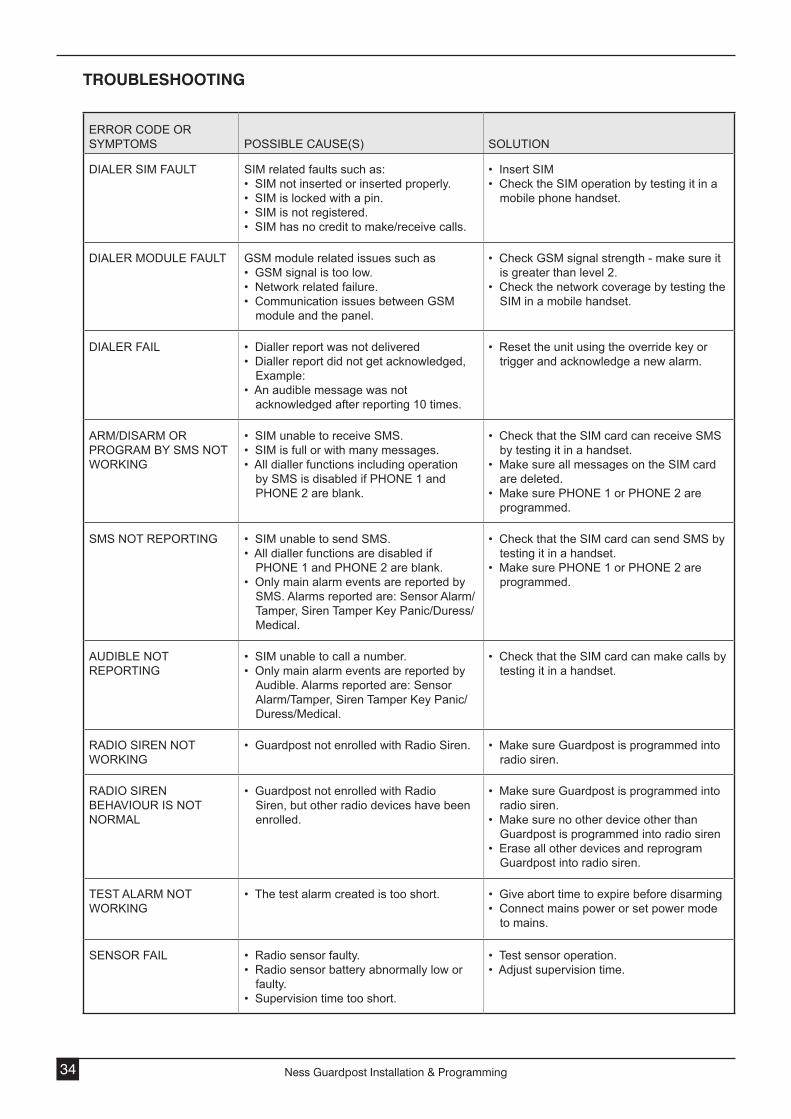
troUbLeSHootINg
ERROR CODE OR SYMPTOMS POSSIBLE CAUSE(S) SOLUTION
DIALER SIM FAULT SIM related faults such as: • SIM not inserted or inserted properly. • SIM is locked with a pin. • SIM is not registered. • SIM has no credit to make/receive calls.
• Insert SIM• Check the SIM operation by testing it in a
mobile phone handset.
DIALER MODULE FAULT GSM module related issues such as • GSM signal is too low.• Network related failure. • Communication issues between GSM
module and the panel.
• Check GSM signal strength - make sure it is greater than level 2.
• Check the network coverage by testing the SIM in a mobile handset.
DIALER FAIL • Dialler report was not delivered• Dialler report did not get acknowledged,
Example: • An audible message was not
acknowledged after reporting 10 times.
• Reset the unit using the override key or trigger and acknowledge a new alarm.
ARM/DISARM OR PROGRAM BY SMS NOT WORKING
• SIM unable to receive SMS.• SIM is full or with many messages.• All dialler functions including operation
by SMS is disabled if PHONE 1 and PHONE 2 are blank.
• Check that the SIM card can receive SMS by testing it in a handset.
• Make sure all messages on the SIM card are deleted.
• Make sure PHONE 1 or PHONE 2 are programmed.
SMS NOT REPORTING • SIM unable to send SMS.• All dialler functions are disabled if
PHONE 1 and PHONE 2 are blank.• Only main alarm events are reported by
SMS. Alarms reported are: Sensor Alarm/Tamper, Siren Tamper Key Panic/Duress/Medical.
• Check that the SIM card can send SMS by testing it in a handset.
• Make sure PHONE 1 or PHONE 2 are programmed.
AUDIBLE NOT REPORTING
• SIM unable to call a number.• Only main alarm events are reported by
Audible. Alarms reported are: Sensor Alarm/Tamper, Siren Tamper Key Panic/Duress/Medical.
• Check that the SIM card can make calls by testing it in a handset.
RADIO SIREN NOT WORKING
• Guardpost not enrolled with Radio Siren. • Make sure Guardpost is programmed into radio siren.
RADIO SIREN BEHAVIOUR IS NOT NORMAL
• Guardpost not enrolled with Radio Siren, but other radio devices have been enrolled.
• Make sure Guardpost is programmed into radio siren.
• Make sure no other device other than Guardpost is programmed into radio siren
• Erase all other devices and reprogram Guardpost into radio siren.
TEST ALARM NOT WORKING
• The test alarm created is too short.
• Give abort time to expire before disarming• Connect mains power or set power mode
to mains.
SENSOR FAIL • Radio sensor faulty.• Radio sensor battery abnormally low or
faulty.• Supervision time too short.
• Test sensor operation.• Adjust supervision time.

35ness Guardpost installation & Programming
SpeCIFICAtIoNS
SYSTEM
ONBOARD PIR 15m PIR motion sensor
ONBOARD SIREN 124dBM
DIALLER Quad band GSM
BATTERY 12 Volt 3.2Ah SLA provides internal power in low-current modes / provides backup power in Mains mode
USER INTERFACE
DISPLAY 6 Character scrolling LED
VOICE FEEDBACK Onboard voice + language options
OPERATION Arm / Disarm / Panic / Programming by radio keys
Arm / Disarm by SMS messaging
EVENT LOG Last 5 events with voice announcement
SETUP
SYSTEM PROGRAMMING Local programming by radio keys
Self learning of radio devices by local programming
Off site programming by SMS messaging
RADIO DEVICES
DEVICES SUPPORTED Up to 24 Ness Radio Keys or Radio Devices including the onboard PIR
RADIO SECURITY Proprietary encryption and supervision
Radio jamming detection
Radio substitution detection
RADIO RX/TX Ness integrated receiver for radio device signals
Ness Radio Siren transmitter onboard
RADIO FREQUENCY 304Mhz / 868MHz depending on local requirements
INPUTS / OUTPUTS
EXTERNAL WIRE LOOM RED/BLACK. Strobe output: 12V strobe light, max. 2
RED/BLUE. Siren output: 8 Ohm horn speaker, max. 1
RED/WHITE. Internal siren output: 12V screamer, max. 1
YELLOW/GREEN. Tamper input: 3k3 end of line (resistor supplied)
RED/RED FLYING LEADS. External input for hardwired 17VAC supply or solar panel supply
EXTERNAL POWER 17VAC Plug Pack supplied for periodic battery charging or for full-time power
External input for hardwired 17VAC supply, (see External Wire Loom)
External input for solar panel power supply, (see External Wire Loom)
PHYSICAL
DIMENSIONS, MAIN UNIT 515(h) x 112(w) x 80mm(d)
COMPLIANCE
APPROVALS C-TICK, CE
