gudlavalleru engineering college concrete technology...
TRANSCRIPT

GUDLAVALLERU ENGINEERING COLLEGE CONCRETE TECHNOLOGY
1 DEPARTMENT OF CIVIL ENGINEERING
CONCRETE TECHNOLOGY LABORATORY
GUDLAVALLERU ENGINEERING COLLEGE SESHADRI RAO KNOWLEDGE VILLAGE: GUDLAVALLERU
DEPARTMENT OF CIVIL ENGINEERING
Name : ………………………………………………………
Regd. No : ……………………………………………………….
Year & Semester :………………………………………………………..
Academic Year : ……………………………………………………….
GUDLAVALLERU ENGINEERING COLLEGE CONCRETE TECHNOLOGY
2 DEPARTMENT OF CIVIL ENGINEERING
GUDLAVALLERU ENGINEERING COLLEGE SESHADRI RAO KNOWLEDGE VILLAGE::GUDLAVALLERU
DEPARTMENT
OF
CIVIL ENGINEERING
GUDLAVALLERU ENGINEERING COLLEGE SESHADRI RAO KNOWLEDGE VILLAGE: GUDLAVALLERU
DEPARTMENT OF CIVIL ENGINEERING

GUDLAVALLERU ENGINEERING COLLEGE CONCRETE TECHNOLOGY
3 DEPARTMENT OF CIVIL ENGINEERING
GUDLAVALLERU ENGINEERING COLLEGE SESHADRI RAO KNOWLEDGE VILLAGE:: GUDLAVALLERU
DEPARTMENT OF CIVIL ENGINEERING
INDEX
S.n
o
Date
Name of the
Experiment
Signatu
re
of the
faculty 1 NORMAL CONSISTENCY AND FINENESS
OF CEMENT
2 INITIAL AND FINAL SETTING TIMES OF CEMENT
3 COMPRESSIVE STRENGTH OF CEMENT
4 SPECIFIC GRAVITY AND BULKING OF
SAND
5 FINENESS MODULUS OF FINE
AGGREGATE AND COARSE AGGREGATE
6
WORKABILITY OF CONCRETE
7 SPECIFIC GRAVITY AND SOUNDNESS
OF CEMENT
8 COMPRESSIVE STRENGTH AND SPLIT
TENSILE STRENGTH OF CONCRETE
9 FLAKINESS INDEX
10 ELONGATION INDEX
11 SPECIFIC GRAVITY OF COARSE
AGGREGATE
12 NON DESTRUCTIVE TESTING OF
CONCRETE

GUDLAVALLERU ENGINEERING COLLEGE CONCRETE TECHNOLOGY
4 DEPARTMENT OF CIVIL ENGINEERING

GUDLAVALLERU ENGINEERING COLLEGE CONCRETE TECHNOLOGY
5 DEPARTMENT OF CIVIL ENGINEERING
EXPERIMENT NO: DATE:
INITIAL AND FINAL SETTING TIMES OF CEMENT
Aim: To determine initial and final setting times for cement by
using vicat’s apparatus.
Apparatus:
Vicat’s apparatus with needle
Stop watch
Balance
100ml measuring jar.
Theory:
Initial setting time: The time interval for which the cement
products remain in "plastic condition" is called initial setting
time.
Final setting time: It is the time interval between moment the
water added to cement and time when the paste has completely
lost its plasticity and has attained sufficient firmness to resist
certain definite pressure.
Procedure:
1. Take 500gms of cement sample and prepare a neat cement
paste with 0.85 times of water to get normal consistency.
2. Start the stopwatch at the instant addition of water . Fill the
vicat mould with above paste completely and smooth off
the surface.
3. Place the test block under rod bearing needle lower the
needle gently in contact with the surface of test block and
quickly release allowing it to penetrate into the test block.
Repeat this experiment until the needle brought in contact
with test block fails to pierce , the block for 33-35mm from
the top of mould , stop the stop watch.
4. The period elapsed since adding water to the moment needle
penetrate to mould is initial setting time.

GUDLAVALLERU ENGINEERING COLLEGE CONCRETE TECHNOLOGY
6 DEPARTMENT OF CIVIL ENGINEERING
5. To determine the final setting time replace the needle in
step 3 by a needle with circular attachment that make
impression on the test block . The cement is considered
finally set, in the above process when the needle makes
impression , while the circular attachment fails to do so. The
total time taken from the instant water is added to the dry
cement to final set stage is known as final setting time.(In
other words, paste has attained such hardness that centre
needle does not pierce through paste form more than
0.5mm)
Precautions:
1. The experiment should be conducted at the room
temperature of 25-29 C at the relative humidity 90%.
2. After all half a minute from the instant of adding water, the
paste should be thoroughly mixed with fingers for at least
one minute.
3. A ball of this paste is prepared and then it is pressed into
best mould.
4. For each repetition of the experiment fresh cement is to be
taken.
Result:
Initial setting time is
Final setting time is

GUDLAVALLERU ENGINEERING COLLEGE CONCRETE TECHNOLOGY
7 DEPARTMENT OF CIVIL ENGINEERING

GUDLAVALLERU ENGINEERING COLLEGE CONCRETE TECHNOLOGY
8 DEPARTMENT OF CIVIL ENGINEERING
EXPERIMENT NO.
DATE:
COMPRESSIVE STRENGTH OF CEMENT
Aim:To determine the compressive strength of 1:3 cement sand
mortor cubes after 3 days,7 days and 28 days curing.
Apparatus:
1. Cube mould of size 7.07x7.07x7.07 cm with base plates.
2. Weighing balance accurate up to 0.1 gm.
3. Mortored cube vibration machine.
4. Measuring cylinder.
5. Trowel and tray etc.
Materials:Cement sample,water and standard sand.
Procedure:
Preparation of test specimen for each cube,take the quantities of
materials(1:3) as follows
Cement =185gms
Standard sand =555gms(ita shauto conform IS 650-1991)
Water =(P/4 +3.0) percent of combined weight of
cement and sand.
Mix the cement and sand with towel on non-porous plate for one
minute.Then add water to the mixture of cement,sand and mix
until the mixture of uniform colour is obtained.The time of
gauging shall be in any case not be less than 3 minutes and not
more than 5 minutes, gauging time is time lapped between the

GUDLAVALLERU ENGINEERING COLLEGE CONCRETE TECHNOLOGY
9 DEPARTMENT OF CIVIL ENGINEERING
water added to mix and casting of cubes.
1. Apply thin layer of oil to the interior faces of mould.Place it on
the table of vibration machine, and firmly hold in position by
means of clamps.
2. Place the entire quantity of mortor in the hopper of the cube
mould and compact the same by vibrations(1200rpm) for period
of about 2 minutes.
3. At the end of vibrations, remove the mould together with
base plate from the machine and finish the top surface of cube in
the mould by smoothing the surface with the blade of
trowel.Engrave identification mark in cubes.
4. Keep the filled moulds in the atmosphere of atleast 90%
relative humidity for 24hrs,after completion of vibration.Also
maintain temperature at 27+20 c.
5. At the end of this period, remove cubes from moulds and
immediately submerge in clean fresh water and keep there until
taken out just prior to breaking.After they are taken out and until
they are broken,the cubes shall not allow to become dry.
Testing:
1. Place the test cube on the platform of compression testing
machine without any packing.
Between cube and steel platens of the testing machine.
2. Apply the load on smooth surface on the cube steadely &
uniform starting from zero at a rate of 35N/mm2/minute till

GUDLAVALLERU ENGINEERING COLLEGE CONCRETE TECHNOLOGY
10 DEPARTMENT OF CIVIL ENGINEERING
cubes fails.
3. Test three such cubes at the end of three days of curing.Three
cubes at end of even days of curing and if needed three cubes
after 28days of curing.
4. Record the crushing load.
5. Calculate the compressive load by strength of each cube by
dividing crushing load by crushing area of cube.The compressive
strength shall be average of the strength of three cubes for each
period of curing.
BIS requirements:
As per IS:268, IS:8112, IS:12269 the average compressive
strength of cement shall be as follows.
S.NO GRADE OF
CEMENT
AFTER 3
DAYS
CURING
N/MM2
AFTER 7
DAYS
CURING
N/MM2
AFTER 28
DAYS
CURING
N/MM2
1 33 GRADE 16 22 33
2 43 GRADE 23 33 43
3 53 GRADE 27 37 53
Results:
The average compressive strength of cement sample is found
to be
1. At the end of 3 days of curing =

GUDLAVALLERU ENGINEERING COLLEGE CONCRETE TECHNOLOGY
11 DEPARTMENT OF CIVIL ENGINEERING
2. At the end of 7 days of curing =
3. At the end of 28 days of curing
Conclusion:
1. The compressive strength of given cement as per sample is
_________________N/mm2.
2. The cement is ____________ grade cement according to BIS
Requirements.

GUDLAVALLERU ENGINEERING COLLEGE CONCRETE TECHNOLOGY
12 DEPARTMENT OF CIVIL ENGINEERING
EXPERIMENT NO:
DATE:
SPECIFIC GRAVITY AND BULKING OF SAND
AIM: To determine the specific gravity of Fine aggregate.
Apparatus:pycnometer, weighing machine.
Theory:Specific gravity is the ratio of the weight of a volume of
the substance to the weight of an equal volume of the reference
substance.
Procedure:
The pycnometer is used for aggregate less than 10mm size.
1.Dry the pycnometer thoroughly& weigh it with the cap (W1).
2. Pycnometer is filled with aggregate to about 1/3 rdand weigh
again.
3. Add sufficient water till top and allow the entrapped air into
escape.
4. After air bubble on the cap gently tight to avoid leakage of
water.
5. Fill the pycnometer with water slowly up to top of cap without
spilling (W3) through the Pipe.
6. Clean the pycnometer by washing with water thoroughly.
7. Fill the pycnometer with only water as alone and weigh it
(W4).
8. Repeat the test twice as more and take the average for better
result.
Precautions:

GUDLAVALLERU ENGINEERING COLLEGE CONCRETE TECHNOLOGY
13 DEPARTMENT OF CIVIL ENGINEERING
1. The aggregate sample should be perfectly dry and
clean.
2. The accuracies in weighing and failure to completely
eliminate the entrapped air are the main source of
error.
3. Cap of the pycnometer with washer should gently to
avoid leakage.
Calculations:
Specific gravity of aggregateG =
W1= Weight of empty pycnometer=
W2= Weight of empty pycnometer +dry
aggregate=
W3= Weight of empty pycnometer + dry
aggregate + water=
W4=Weight of empty pycnometer + water =
Result: The specific gravity of aggregate =

GUDLAVALLERU ENGINEERING COLLEGE CONCRETE TECHNOLOGY
14 DEPARTMENT OF CIVIL ENGINEERING
(b) BULKING OF SAND
Aim: To study the behaviour of sand grains under varying
percentage of moisture content.
Apparatus: 250ml measuring cylinder, weighing balance etc.
Theory: In volume batching of concrete, dry quantity of fine
aggregate to be added depends upon the volume of cement. Free
moisture forms a film around each particle. This film of moisture
exerts what is known as surface tension which keeps the
neighbouring particles away from it. Therefore no point contact is
possible between particles. This causes bulking of sand means
increases in volume of sand.
Procedure:
1. Take 500gm (W1) of aggregate.
2. Keep the sample in an oven in a tray at a temperature of
1000c – 1100c for 24+0.5 hrs.
3. Cool the sand in air tight container and weigh it (W2) water
content of the sample
= ((W1-W2)/W1)*100
4. Take out about 250gm of sand and pour it into a pan.

GUDLAVALLERU ENGINEERING COLLEGE CONCRETE TECHNOLOGY
15 DEPARTMENT OF CIVIL ENGINEERING
5. Add 2% (by weight) water and mix it well.
6. Pour the sand sample into a 250ml measuring cylinder and
consolidate by shaking.
7. Level the surface and read the volume in ml.
8. Take out the whole quantity of sand and continue the
experiment by adding 2% water more each time and note the
corresponding volume of sand until the dump sand volume starts
decreasing.
9. Beyond this point, add 4% more water each time until the
sample become fully saturated.
10. To standard cylinder sample in measuring cylinder, add 50ml
water more and stir sample well and note down surface level of
sand.
Graph:
A graph is drawn with% of water content along X – axis and %
bulking along Y – axis. From the graph pick out maximum % of
bulking occurred, % of water content at maximum fulfilling of
water content.
Results: (a). % of Bulking of Sand:
(b). % of water content at maximum bulking:

GUDLAVALLERU ENGINEERING COLLEGE CONCRETE TECHNOLOGY
16 DEPARTMENT OF CIVIL ENGINEERING
EXPERIMENTNO:
DATE:
FINENESS MODULUS OF FINE AGGREGATE AND COARSE AGGREGATE
Aim: To determine the fineness of modulus of fine aggregate and
coarse aggregate.
Apparatus: Indian standard test sieves set , weighting balance
, sieves shaker pan , tray.
Definition: it is defined the average cumulative % retained by
100 was known as fineness modulus
Theory: Fineness modulus is a numerical index used to
know the mean size of particle in the total Quantity of
aggregate . Fineness modulus is to grade the given aggregate
for most economical mix And workability with less assumption
of cement lower FM gives uneconomical mix and higher FM
gives harsh mix.
Procedure:
1. Arrange the test services with larger openings at top and
smaller openings at bottom and finally below all keep a pan
2. Take 1 kg of sand in to a tray and break the lumps , if any in
case of fine aggregate and 1kg of samples in the case of
coarse aggregate and mixed aggregate.

GUDLAVALLERU ENGINEERING COLLEGE CONCRETE TECHNOLOGY
17 DEPARTMENT OF CIVIL ENGINEERING
3. Keep the sample in the top sieve and keep the total set in
the top sieve and keep the total sSet in the shaker
.continue sieving for a period not less than 10minutes .
weigh the material retained on each sieve property
Precautions:
Sample should be taken by quartering.
Careful sieving must be done to prevent any spilling of
aggregate
Graph: Draw a graph between IS sieve size (in log scale) and
%passing.
Specification: The following limits may be taken as guidance.
Fine sand : F.M—2.2—2.6
Medium sand : F.M—2.6—2.9
Coarse sand:F.M—2.9—3.2
observation: Weight of sample for fine aggregate=
Weight of sample for coarse aggregate=
Observation: Fine aggregate
s.no IS sieve
size
Wt
retained
Gm
%
retained
%
passing
Cumulative
%
Retained
1 4.75mm
2 2.36mm
3 1.18mm
4 600 µ
5 300 µ
6 150 µ
Observation: coarse aggregate
s.no IS sieve
size
Wt
retained
Gm
%
retained
%
passing
Cumulative
%
Retained
1 80mm
2 40mm

GUDLAVALLERU ENGINEERING COLLEGE CONCRETE TECHNOLOGY
18 DEPARTMENT OF CIVIL ENGINEERING
3 20mm
4 10mm
5 4.75mm
6 2.36mm
7 1.18mm
8 600 µ
9 300 µ
10 150 µ
Result:
Fineness modulus of fine aggregate =
Fineness modulus of coarse aggregate=
EXPERIMENT NO:
Date:
WORKABILITY OF CONCRETE
AIM: To determine the consistency of concrete mixes by
1. Slump cone test
2. Vee-bee Consistometer
3. Compaction Factor Test
where the normal size of aggregate doesn’t exceed 38mm
APPARATUS:
Conical mould, Tampering rod, Vee-Bee consistometer,
Compaction Factor Apparatus, Flow Table, Steel scale, weighing
balance, Measuring jar, Trowel, Stopwatch.
THEORY:

GUDLAVALLERU ENGINEERING COLLEGE CONCRETE TECHNOLOGY
19 DEPARTMENT OF CIVIL ENGINEERING
Fresh unsupported concrete will flow to the sides and the vertical
sinking of concrete is known as slump. Slump, vee-bee time,
compaction factor and flow index are names used to indicate the
consistency and workability of cement concrete should not show
any segregation (separation of coarse aggregate and fine
aggregate) or bleeding ( excess of water coming to the surface of
concrete).
PROCEDURE:
a) SLUMP CONE TEST:
1. Weigh the constituents of concrete in dry state. First mix
cement and sand thoroughly to get a uniform colour. Make
a dip at centre of heap and pore some part of already
weighed water.
2. Clean the internal surface of the mould and place it over a
smooth horizontal and non
3. Absorbent surface firmly held the plate in position and
filled it with fresh concrete in four equal layers.
4. Using the tampering rod or a trowel strike of the excess
concrete above the concrete cone. Measure the vertical
height of cone(h1).
5. Slowly and carefully remove in the vertical direction. As
soon as the cone is removed the concrete settles in
vertical direction. Place the steel scale above top of settled
concrete in horizontal position and measure the height of
cone(h2).
6. Complete the experiment in two minutes after sampling.
7. The difference of two heights (h1-h2) gives the value of
slump.
PRECAUTIONS:
1) The experiment should be completed in three minutes.
2) Care should be take not to cause subsidence by jarring
the base.
3) Test must be conducted beyond the range vibration.
b) VEE-BEE CONSISTOMETER:

GUDLAVALLERU ENGINEERING COLLEGE CONCRETE TECHNOLOGY
20 DEPARTMENT OF CIVIL ENGINEERING
1) Clean the internal surface of the module and place it
inside the sheet metal cylindrical pot of the consistometer.
Firmly held the cone in position and fill it with fresh
concrete in four equal layers.
2) Tamp each layer of concrete with the tamping rod for 25
times distributing the blows in a uniform manner over the
c/s of mould. For the second and subsequent layer the
tamping rod should penetrate into the preceding layers.
3) Using the tamping rod or a trowel strike off the excess
concrete above the top of the cone. Attach the glass disc
to the swivel arm. Place the glass disc over the slump
cone and note the position.
4) Turn the swivel slowly and carefully remove the cone in
the vertical direction as soon as the cone is removed, turn
the swivel arm and place the glass plate over the concrete
cone.
5) Switch on the electric vibrator of the vee-bee
consistometer. Simultaneously, start the stop watch.
Continue the vibration until the whole concrete surface
uniformly adheres to the glass disc. At this stage, stop
watch and note the elapse time in seconds.
6) Express the consistency of concrete in Vee-Bee time which
is equal to the elapse time in seconds.
c) COMPACTION FACTOR TEST:
1) Apply grease to the inner surface of the hoppers and
cylinders.
2) Fasten the hopper doors.
3) Weight the empty cylinder(w1). Fix the cylinder at the
centre of the hopper (i.e. insert in the appropriate holes)
4) Fill the upper hopper with freshly mixed concrete , without
any compaction. After two minutes release the trap door,
allowing the concrete to fall into the lower hopper and
bringing the concrete into standard compaction.
5) As soon as the concrete comes to rest release the trap
door of the lower hopper and allow concrete to fall into the

GUDLAVALLERU ENGINEERING COLLEGE CONCRETE TECHNOLOGY
21 DEPARTMENT OF CIVIL ENGINEERING
cylinder. Remove the excess concrete above the top
surface of cylinder with a trowel, without any compaction.
Clean sides of the cylinder and note the weight of the
cylinder with partially compacted concrete (w2).
6) Empty the cylinder and refill it with same sample of
concrete with 5cm layers heavily compacting each layer to
expel all air and to obtain full compaction of concrete,
strike of the excess concrete and weigh the cylinder with
fully compacted concrete(w3)
7) The ratio of the weights of partially compacted concrete to
fully compacted concrete (w2-w3)/(w3-w1) gives the
compaction factor.
RESULT:
1) Slump of concrete=
2) Vee-Bee time=
3) Compaction factor=
GUDLAVALLERU ENGINEERING COLLEGE CONCRETE TECHNOLOGY
22 DEPARTMENT OF CIVIL ENGINEERING
EXPERIMENT No: DATE:
NORMAL CONSISTENCY AND FINENESS OF CEMENT
(a) Normal Consistency of Cement
Aim: To determine normal consistency of cement by using
vicat’s apparatus.
Apparatus: Vicat apparatus with plunger, balance, stopwatch
measuring jar.
Theory: The normal consistency of cement past is defined as
percentage of water which permits the vicat plunger to penetrate
to a point 5 to 7mm from the bottom or 33-35mm from the top
of the mould when the given cement past is tested.
Procedure:
1. Take about 500 gms of cement and prepare a paste with a
weighed quantity of water (say 24 percent by weight of
cement) for the first trail. The mixing should be done in
between 3-5 min, the time is counted from the time
of adding water to dry cement until the commencement of
filling mould. After completely filling the mould, shake the
mould to expel air.
2. Fill the vicat mould with the paste, the mould is resisting on
a non porous plate & then smooth off the surface of the
paste making it level with the top of the mould.
3. Paste the test block in the mould together with non porous
resisting place under the load bearing the plunger, lower the
plunger of 50mm long and 10mm dia gently to touch the
surface of test block quickly release, allowingit into sink into
the paste. The operation shall be carried out immediately
after filling the mould at rooms temperature.
4. Prepare trail paste with varying percentage of water & test
as described above & measure the penetration of plunger.
This test is to be carried out until the specified penetration
is obtained.
Observations and Calculations:
GUDLAVALLERU ENGINEERING COLLEGE CONCRETE TECHNOLOGY
23 DEPARTMENT OF CIVIL ENGINEERING
Consistency is expressed as % of water required to
penetrate 33-35 mm from top of mould or 5-7 mm from bottom
of mould added by weight of cement & penetration is expressed
in mm.
Precautions:
The experiment should be conducted at room temperature
of 25 + 2C @ a relative humidity of 90%.
After ½ minute from instant of adding water, the paste
should be thoroughly mixed with fingers for at least 1 min. A ball
of this paste is prepared & then it is present into the test mould,
mounted on the non porous place. Plunger should be cleaned
during every reputation.
Result: Normal consistency of cement is

GUDLAVALLERU ENGINEERING COLLEGE CONCRETE TECHNOLOGY
24 DEPARTMENT OF CIVIL ENGINEERING
(b) Fineness of Cement
Aim: to determine the fineness of the cement of the given
sample by dry sieving.
Apparatus: IS: 9(90µ) test sieve confirming to IS 460-1972
with bottom pan, weighing balance, bristle brush.
Theory: The degree of fineness of cement is a measure of the
mean size of the grains. The finer cement has quicker action
with water and gains early strength without change in the
ultimate strength. Finer cement is susceptible to shrinkage and
cracking. A correction factor is to be applied for fineness of
cement as all sieves are not exactly alike.
Procedure:
1. Accurately weigh 100 gm of cement sample and place it
over the test sieve. Gently breakdown the air set lumps if
any with fingers.
2. Hold the sieve with pan in both hands and sieve with gentle
wrist motion, in circular and vertical motion for a period of
10 to 15 minutes without any spilling of cement.
3. Place the cover on the sieve and remove the pan. Now tap
the other side of the sieve with the handle of bristle brush
and clean the outer side of the sieve.
4. Empty the pan and fix it below the sieve and continue
sieving as mentioned in the steps 2 and 3. Totally sieve for
15 minutes and weigh the residue (Left over the sieve)
Specification: Weight shall not exceed 10% for ordinary
cement.
Precautions:
1. Air set lumps should be break down gently with fingers
without rubbing on the sieve

GUDLAVALLERU ENGINEERING COLLEGE CONCRETE TECHNOLOGY
25 DEPARTMENT OF CIVIL ENGINEERING
2. The sieve must be clean thoroughly before starting the
experiment.
3. While sieving care must be taken to prevent in spilling of
cement.
Observations:
Weight of cement taken =
Weight of cement retained after sieving =
Result:
Fineness of the given sample is
Experiment No:
Date:
ELONGATION INDEX
AIM: To determine Elongation Index of the aggregate.
APPARATUS: The apparatus consists of the length gauge ,
sieves of the sizes specified in table 5.1 and a balance.
PROCEDURE:
The sample is sieved through the sieves specified. A
minimum of 200 pieces of each fraction is taken and weighed. In
order to separate elongated material, each fraction is then
gauged individually for length gauge .The gauge length used
should be those specified will used for appropriate material. The
pieces of aggregates from each fraction tested which could not
pass through the specified gauge length with its long side are
elongated particles and are collected separately to find the total
weight of aggregate retained by the length gauge are weighed
to an accuracy of atleast 0.1 percent of the weight of the sample.
CALCULATION:
In order to calculate the elongation index of the entire
sample of aggregates , the weight of aggregates which is
retained on the specified gauge length from each fraction is
GUDLAVALLERU ENGINEERING COLLEGE CONCRETE TECHNOLOGY
26 DEPARTMENT OF CIVIL ENGINEERING
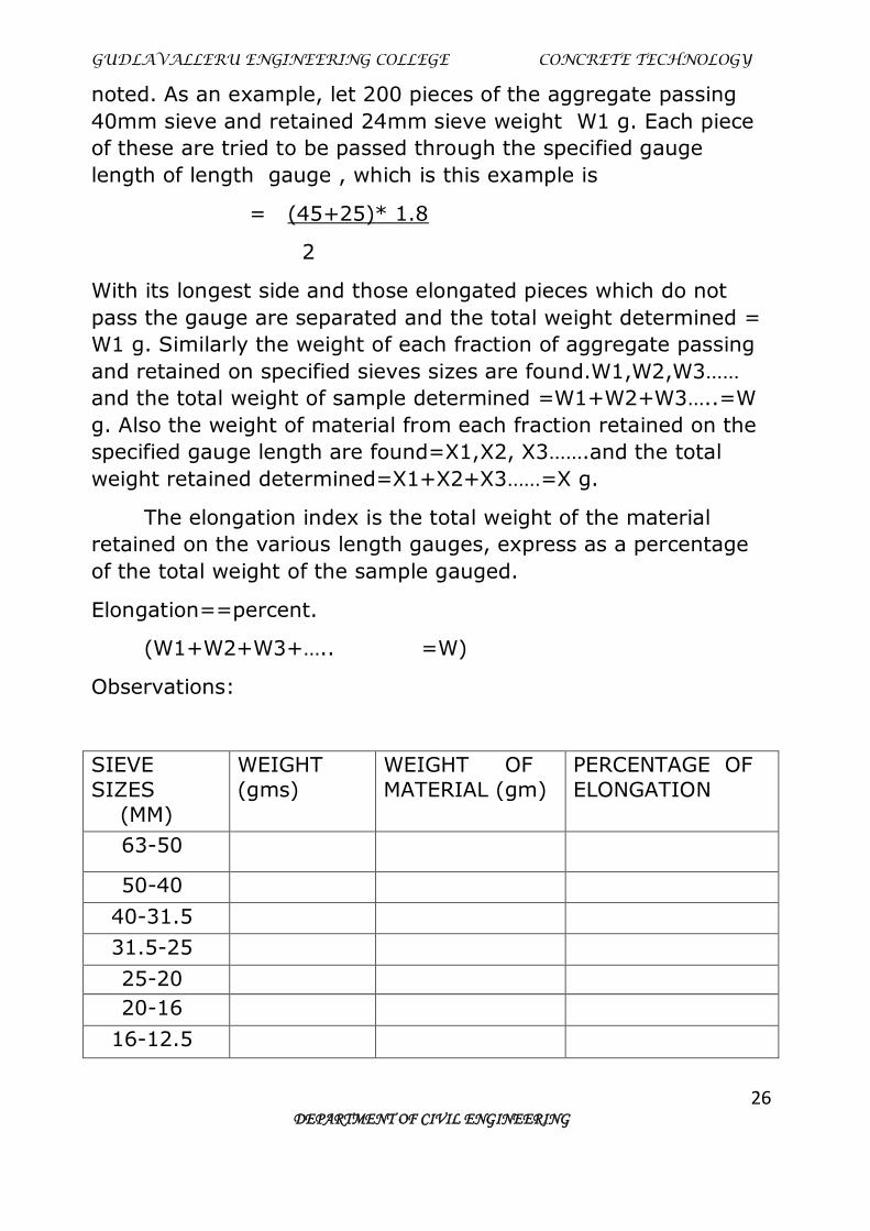
noted. As an example, let 200 pieces of the aggregate passing
40mm sieve and retained 24mm sieve weight W1 g. Each piece
of these are tried to be passed through the specified gauge
length of length gauge , which is this example is
= (45+25)* 1.8
2
With its longest side and those elongated pieces which do not
pass the gauge are separated and the total weight determined =
W1 g. Similarly the weight of each fraction of aggregate passing
and retained on specified sieves sizes are found.W1,W2,W3……
and the total weight of sample determined =W1+W2+W3…..=W
g. Also the weight of material from each fraction retained on the
specified gauge length are found=X1,X2, X3…….and the total
weight retained determined=X1+X2+X3……=X g.
The elongation index is the total weight of the material
retained on the various length gauges, express as a percentage
of the total weight of the sample gauged.
Elongation==percent.
(W1+W2+W3+….. =W)
Observations:
SIEVE
SIZES
(MM)
WEIGHT
(gms)
WEIGHT OF
MATERIAL (gm)
PERCENTAGE OF
ELONGATION
63-50
50-40
40-31.5
31.5-25
25-20
20-16
16-12.5

GUDLAVALLERU ENGINEERING COLLEGE CONCRETE TECHNOLOGY
27 DEPARTMENT OF CIVIL ENGINEERING
12.5-10
10-6.3
RESULT: Mean percentage of elongation =

GUDLAVALLERU ENGINEERING COLLEGE CONCRETE TECHNOLOGY
28 DEPARTMENT OF CIVIL ENGINEERING
EXPERIMENT NO: DATE:
FLAKINESS INDEX
AIM: To determine flakiness index of given aggregate.
APPARATUS: Standard thickness gauges, I.S sieves of sizes 63,
50,40, 31.5 , 25, 20, 16, 12.5, 10 and 6.3 mm and a balance .
THEORY: The flakiness index of aggregate is percentage by
weight of particles in it whose least dimension (thickness) is less
than (3/5 th) of their mean dimension . The test is not applicable
to sizes smaller than 6.3 mm.
PROCEDURE:
1. Sample is sieved with sieves mentioned and 200 pieces of
each fraction to be tested are taken and weighed as W1 gr.
2. Flaky material is separated by a thickness gauge or sieves
with elongated slots.
3. Width of slot used should be according standards for material
.
4. The amount of flaky material is weighed to 0.1 % accuracy
of test sample.
5. The flakiness index is the total weight of material passing
through various thickness gauges expressed as percentage
of total weight of sample taken.

GUDLAVALLERU ENGINEERING COLLEGE CONCRETE TECHNOLOGY
29 DEPARTMENT OF CIVIL ENGINEERING
Calculations:
1. Sum of weight of all fractions retained on different sieve
sizes W=
2. Sum of weight of all fractions passing through different
sieves W=
Flakiness index = ( sum of weights of the flaky material /
sum of weight of aggregates) * 100 RESULT :
Flakiness index =
SIEVE SIZES Wt. of aggregate (gr) Wt. of flaky material (gr)
50
40
31.5
25
20
16
12.5
10
6.3

GUDLAVALLERU ENGINEERING COLLEGE CONCRETE TECHNOLOGY
30 DEPARTMENT OF CIVIL ENGINEERING
EXPERIMENT NO:
DATE:
SPECIFIC GRAVITY AND SOUNDNESS OF CEMENT
(a) Specific Gravity of Cement
Aim: To determine the specific gravity of cement using Le-chatlier
flasks or specific gravity bottle.
Apparatus: Lechatlier’s flask or specific gravity bottle, 100ml,
capacity balance capable of weighing accurately upto 0.1gms.
Procedure: Weigh a clean, dry, lechatlier’s flask or specific gravity bottle with
stopper (W1). Place sample of cement upto half of flask about
500gms and weigh with its stopper (W2). Add kerosene (polar
liquid) to cement in flask till its about half full mix thoroughly
with glass rod to remove entrapped air continue strings & add
more kerosene, till its flush with graduated mark. Now weigh the
bottle (W3). Now remove the cement and kerosene and clean it
thoroughly. Fill the bottle with kerosene and weight it (W4).
Observations:
Weight of empty flask W1=
Weight of empty flask + cement W2=
Weight of empty flask + cement + kerosene W3=
Weight of empty flask + kerosene W4=
Specific Gravity of kerosene GK=
Specific Gravity of cement =
precautions:
GUDLAVALLERU ENGINEERING COLLEGE CONCRETE TECHNOLOGY
31 DEPARTMENT OF CIVIL ENGINEERING
1. The cement sample should be perfectly dry and clean and
take weight along with liquid
2. The accuracy in weighing and failure to completely eliminate
the entrapped air are the main source of error
3. Cap of the density bottler with washer should gently to avoid
leakage
Result: Specific Gravity of cement =
(b) SOUNDNESS OF CEMENT
Aim : To determine soundness of cement by Le-chatlier’s
apparatus.
APPARATUS:
Le-chatlier’s apparatus
Weighing balance accurate up to 0.1 gm.
Water bath with electric heating arrangement
Measuring cylinder
Glass plates
THEORY: Unsoundness in cement is due to the presence of
excess of lime than that could be combined with acidic oxide at
kiln. This is also due to the inadequate burning or insufficiency in
fineness of grinding or through mixing of raw materials.
PROCEDURE:
1. Prepare a cement paste formed by gauging cement with 0.78
times water rag to give a paste of standard consistency. The
gauging time should not be less than 3 minutes nor greater
than 5 min.
2. On the inner surface of mould . place the mould on glass
sheet & fill it with cement paste taking care to keep the
edges of the mould gently together cover the mould with
another piece of glass sheet & place a small weight on this

GUDLAVALLERU ENGINEERING COLLEGE CONCRETE TECHNOLOGY
32 DEPARTMENT OF CIVIL ENGINEERING
covering glass sheet & immediately sulnnerage the whole
assembly in water at a temp of 270 c & keep it for 24 hrs.
3. Take out the assembly from water after 24 hrs measure the
distance flow the indicator points & record its (D1).
4. Submerge the mould again in water and bring the water to
boiling in 25 to 30 minutes & keep it boiling for 3 hrs.
5. Remove the mould from the water. Allow it to cool& measure
the distance the indicator points & record it (D2). The
difference b/w two measurements represents the same
expansion of cement.
6. The sample should be tested & average of the results should
be reported.
SPECIFICATIONS:
This must not exceed to 10 mm for ordinary , rapid
hardening and low heat Portland cements. In case expansion is
more than 10 mm as tested above ,cement is said to be
unsound.
RESULT:
The expansion of the cement in the Le-chatlier’s apparatus is
found to be

GUDLAVALLERU ENGINEERING COLLEGE CONCRETE TECHNOLOGY
33 DEPARTMENT OF CIVIL ENGINEERING
EXPERIMENT NO: DATE:
SPECIFIC GRAVITY OF COARSE AGGREGATE
AIM: To Determine specific gravity of aggregates.
APPRATURS: Pycnometer, weighing balance
THEORY:
The coarse aggregate specific gravity test is used to calculate the
specific gravity of a coarse aggregate sample by determining the
ratio of the weight of a given volume of aggregate to the weight
of an equal volume of water.
PROCEDURE:
1. Dry the pycnometer thoroughly and weight with cap (W1)
2. Pycnometer is filled with aggregate to about 1/3rd and weight
it again
3. Add sufficient water till top and allow the entrapped air into
escape
4. After air bubble on the cap gently tight to avoid leakage of
water

GUDLAVALLERU ENGINEERING COLLEGE CONCRETE TECHNOLOGY
34 DEPARTMENT OF CIVIL ENGINEERING
5. Fill the Pycnometer with water slowly up to top of cap
without spilling (W3) through pipe
6. Clean the Pycnometer by washing with water thoroughly
7. Fill the Pycnometer with only water as alone and weight it
(W4)
8. Repeat the test twice as more and take the average for
better result
PRECAUTIONS:
4. The aggregate sample should be perfectly dry and clean and
take weight along with liquid
5. The accuracy in weighing and failure to completely eliminate
the entrapped air are the main source of error
6. Cap of the Pycnometer with washer should gently to avoid
leakage
CALCULATIONS:
Specific gravity of aggregate G =
W1 = weight of empty Pycnometer =
W2 = weight of empty Pycnometer + dry aggregate =
W3 = weight of empty Pycnometer + dry aggregate + water =
W4 = weight of empty Pycnometer + water =
SPECIFICATIONS:
The specific gravity of rock varies from 2.6 – 2.8
RESULT:
The specific gravity of aggregate
EXPERIMENT NO : DATE:
NON DESTRUCTIVE TESTING OF CONCRETE
AIM:
To test the concrete specimen by the non-destructive test
methods i.e., Schmidth’s rebound hammer.
APPARATUS: Schmidith hammer
THEORY :

GUDLAVALLERU ENGINEERING COLLEGE CONCRETE TECHNOLOGY
35 DEPARTMENT OF CIVIL ENGINEERING
In actual structure at a construction site or for a old
structure , it is not possible to estimate the strength directly.
Some assessment of quality of concrete as well as of the
uniformity of casting of a structure can however be obtained by
non-destructive tests. It travels through the material at a
velocity which is dependent on the nature of the material .
It consists of a spring control hammer that slides on a
plunger within a tubular housing. When the plunger is pressed
against the surface of the concrete, the mass rebound from the
plunger. It retracts against the force of the spring. The hammer
impacts against the concrete and the spring control mass
rebounds, taking the rider with it along the guide scale. By
pushing a button , the rider can be held in position to allow the
reading to be taken. The distance travelled by the mass , is
called the rebound number. It is indicated by the rider moving
along a graduated scale.
Each hammer varies considerably in performance and needs
calibration for use on concrete made with the aggregates from
specific source. The test can be conducted horizontally,
vertically- upwards or onwards or at any intermediate angle. At
each angle the rebound number will be different for the same
concrete and will require separate calibration or correction chart.
PROCEDURE :
1. The specimen to be tested should be cleaned in such a way
that the softening or hardening of the surface due to baching
of calcium hydroxide is avoided. Corrosion or Carbonation is
avoided.
2. The specimen surface shall be cleaned of dust or any loose
material .
3. The specimen surface shall be held or fixed in such a way
that it does not yield under the (important) impact of
hammer.
4. The plunger or hammer always be kept perpendicular to the
surface.
GUDLAVALLERU ENGINEERING COLLEGE CONCRETE TECHNOLOGY
36 DEPARTMENT OF CIVIL ENGINEERING
5. About 10-12 readings, shall be taken and their average value
can be calculated to get representative index of hardness.
PRECAUTIONS:
1.All the readings which are to be compared shall be
taken while keeping the hammer in a specified inclination with
the vertical, with the hammer pointing always in the same
direction.
2.For the same surface the readings taken vertically are
likely to be different from those taken by keeping the hammer in
the horizontal portion.
RESULT:
Compressive strength by rebound hammer =

GUDLAVALLERU ENGINEERING COLLEGE CONCRETE TECHNOLOGY
37 DEPARTMENT OF CIVIL ENGINEERING
EXPERIMENT NO:
DATE:
COMPRESSIVE STRENGTH AND SPLIT TENSILE
STRENTH OF CONCRETE
AIM: To determine the cube strength and split tensile strength of
the given concrete.
Apparatus:
Compression tasting machine confirming to IS: 516-1959, cube
moulds 15 cm in size, cylinder moulds 15 cm in dia & 300 m ht.
prism moulds 10 cm ×10 cm ×50 cm, tamping rod, and
weighing machine. The moulds should be made of stool or cast
iron with an internal tolerance of ±0.025 mm. when the mould is
properly assembled, its dimensions should be correct to ±0.2
mm &all internal angles b/w internal faces should be 90±0.5. the
interior faces of the mould shall be plane surfaces with a
permissible variation of 0.03 mm. when the cylindrical mould is
assembled for use, the should be atlest 6.5 mm thick & such that
they do not depart from a plane surface by more than 0.02 mm.
Procedure:
A) Preparation of test specimens:
1) Weight the quantities of cement, fine aggregate, coarse
aggregate and water for one
batch of concrete, to an accuracy of 0.1% of the total weight
of batch.
2) Mix the concrete by hand or preferably in laboratory batch
mixer avoiding loss of any material or water. The period of
mixing should not be less than two minutes after adding all
materials in drum, in case machine mixing.
3) In case of hand mixing first mix cement and fine aggregate
until a uniformly blended mixture is obtained. Add coarse
aggregate to the earlier mix and mix all materials and until all
materials are uniformly spread throughout the batch. Add
GUDLAVALLERU ENGINEERING COLLEGE CONCRETE TECHNOLOGY
38 DEPARTMENT OF CIVIL ENGINEERING
water and mix the entire batch until the all materials are
uniformly concrete appears to be homogeneous and attain the
required consistency.
4) Apply a thin coat of oil to the base plate and interior faces of
the moulds, prevent adhesion of concrete.
5) Fill the moulds with fresh concrete in layers approximately 5
cm deep, place the concrete with a travel, moving it around
top edge of the mould, allowing the concrete to slide in a
symmetrical manner without any segregation.
6) In case of compaction by vibration place the mould on
vibration table &vibrate each layer until the specified condition
reached.
7) In case of hand compaction each layer should be well
tamped by using standard tamping rod, distributing the over
entire surface. The no. of blows required for each layer, to
obtain specific condition are
(a) 15 cm cubical moulds –not less than 35 blows
(b) cylindrical specimens – not less than 30 blows. The
strokes must penetrate into the underlying layer & it
should be rodded throughout its depth. Tap the sides of
mould to close the voids left by tamping.
8) After filling the moulds & compaction, remove the excess
material using trowel. Immediately after doing the above
procedure, cover the moulds with wet mats.
9) Prepare a rich & sift cement paste, for about two to four
hours before application on the specimens to avoid shrinkage.
Cap the by means of glass plate, generally two to hrs or
more often moulding.
10) Stone the test specimen for 24±1/2 hour in moist air of 90%
relative humidity & at a room temp of 27±2®C. The
measurement of time begins at the instant water is added to
dry ingredients. Then remove the specimens from the moulds
& transfer to fresh water or saturated time solution, if tests

GUDLAVALLERU ENGINEERING COLLEGE CONCRETE TECHNOLOGY
39 DEPARTMENT OF CIVIL ENGINEERING
are not require immediately. The water or time solution must
be renewed for every 7 days until are conducted.
B) testing of specimens:
1) cubes & cylinders for compressive strength:
1) Before testing the ends of specimen should be capped with a
material whose compressive strength is greater than that of
concrete in the core.
2) Take the specimens form curing tank and wipe off the grift
and surface water and remove projecting pins, -note the
dimensions of the specimens to the nearest o.2 mm & their
weight.
3) Clean the bearing surfaces of the testing machine. Place the
cubical specimens in such a manner that the load is applied to
opposite sides of the cubes as cast. The cylinders should be
placed in vertical direction. No packing should be used b/w
the test specimen and stool plate of the testing machine.
4) Rotate the movable spherical seated block and rest over the
top of the specimen with proper bearing. Now apply load
without any shock and continuously increase at the rate of
approximately at 140 kg/ sq cm per min until no greater load
is sustained by the specimen. Note the max load applied to
the specimen.
5) Calculate the cube strength or cylindrical strength as the
ratio of max applied to mean c-s area of the specimen and
express to the market kg/sq cm.
6) Average of three values should be taken as representative
of the batch provided the individual variation is not more than
+15%of the average unless repeat the tests.
Split tensile test:

GUDLAVALLERU ENGINEERING COLLEGE CONCRETE TECHNOLOGY
40 DEPARTMENT OF CIVIL ENGINEERING
1) After specified period of curing take the cylindrical specimens
from curing tank & wipe off the grit & surface water. Note the
dimensions of the specimens & their
weights.
2) Draw a diameteral line on the two ends of the specimen
using a suitable procedure.
3) Clean the bearing surfaces of the testing machine. Place one
of the plywood strips centered along the centre of the lower
plate.
4) Place the specimen on the strip in horizontal direction & also
so that the diameteral lines marked on the ends of the
specimen are vertical & centered along the plywood strip.
5) Place the second ply wood strip on the cylinder in length wise
& centered on the marked lines & fix the specimen by bringing
down upper plates.
6) Gently apply the load without any shock & continuously
increase the load at the rate to produce a splitting tensile
stress of approximately 14 to 21 kg/ sq/ cm/ min until no
greater load is sustained by the specimen. Record the max
load applied to the specimen.
Result:
Avg cube compressive strength at 7 days=
Avg cube compressive strength at 14 days=
Avg cube compressive strength at 28 days=
Avg split tensile strength=