guidance for load factor rating (lfr) for corrugated metal ...guidance for load factor...
TRANSCRIPT
Guidance for Load Factor RatingGuidance for Load Factor RatingGuidance for Load Factor RatingGuidance for Load Factor Rating (LFR) for Corrugated Metal Structures(LFR) for Corrugated Metal Structures(LFR) for Corrugated Metal Structures(LFR) for Corrugated Metal Structures
The guidances provided herein are applicable to corrugated metal structures (steel and
aluminum) and structural plate box culverts buried in the soil. The guidances are divided into
two parts, viz. Part A and Part B.
Part A guidance is applicable to the following structure types:
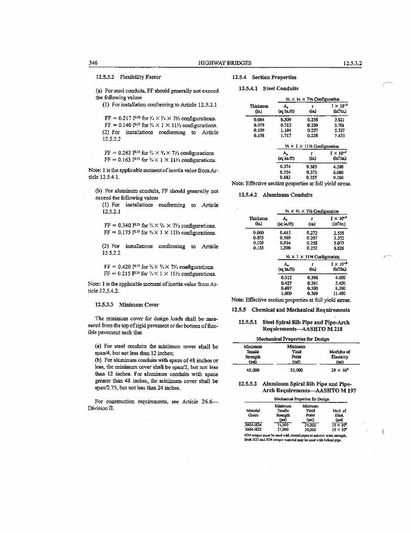
1. Corrugated Metal Pipe as described in AASHTO Standard Specifications for Highway
Bridges, 17th edition, section no. 12.4.
2. Spiral Rib Metal Pipe as described in AASHTO Standard Specifications, section no. 12.5.
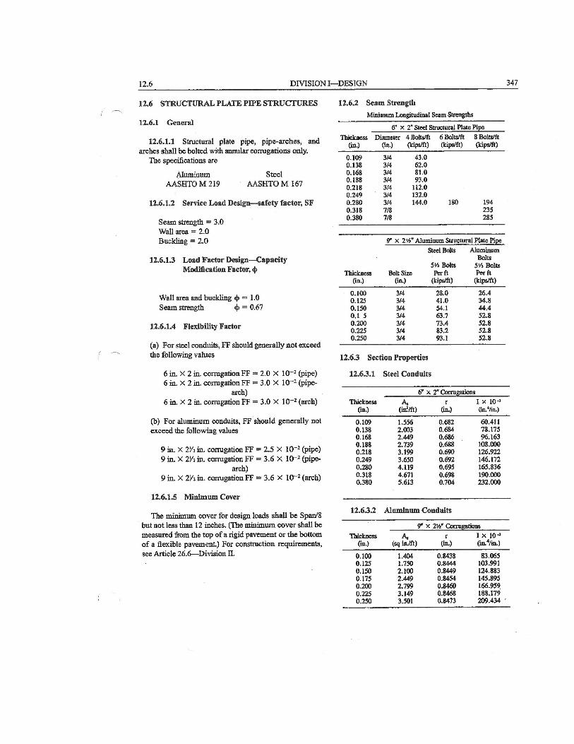
3. Structural Plate Pipe Structures as described in AASHTO Standard Specifications, section
no. 12.6.
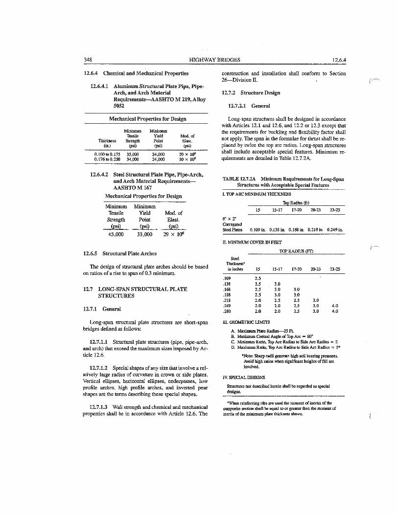
4. Long Span Structural Plate Structures as described in AASHTO Standard Specifications,
section no. 12.7.
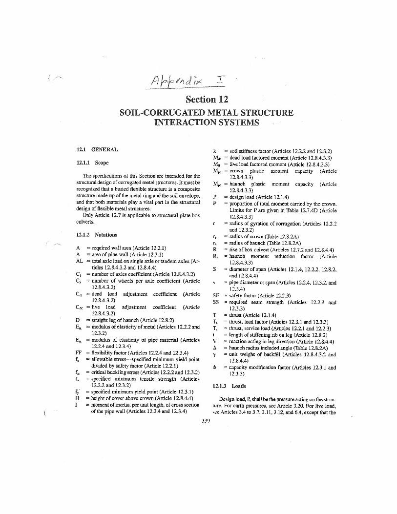
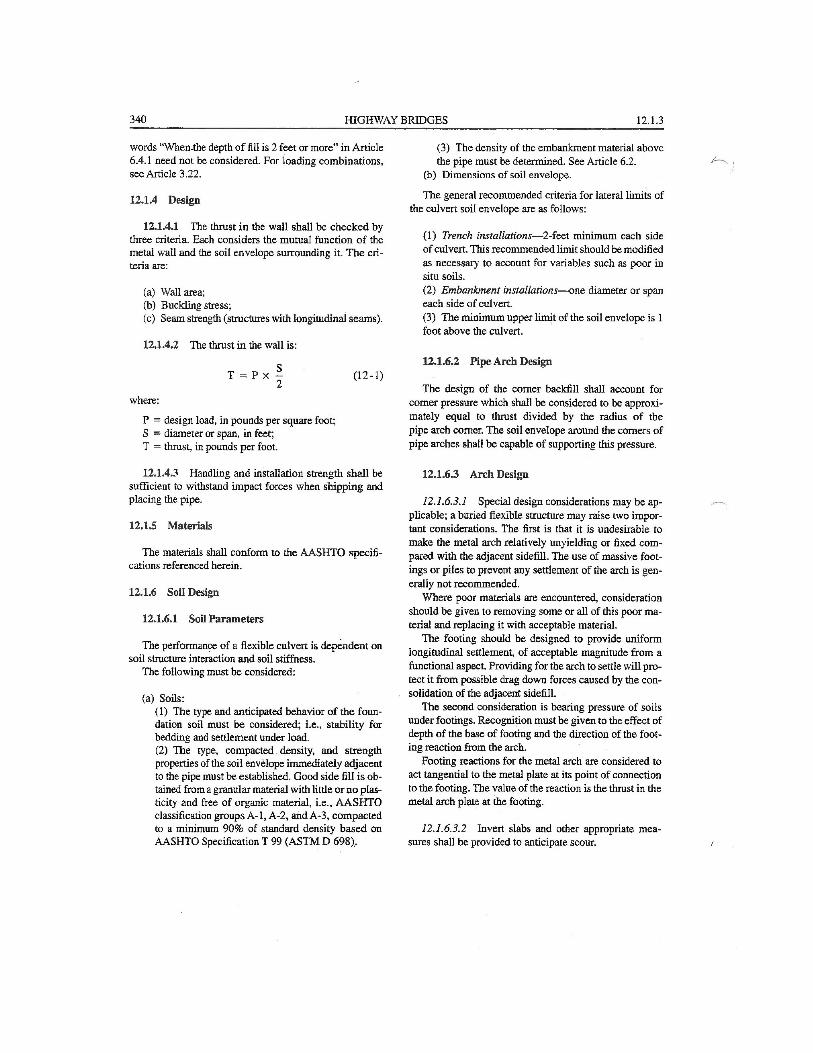
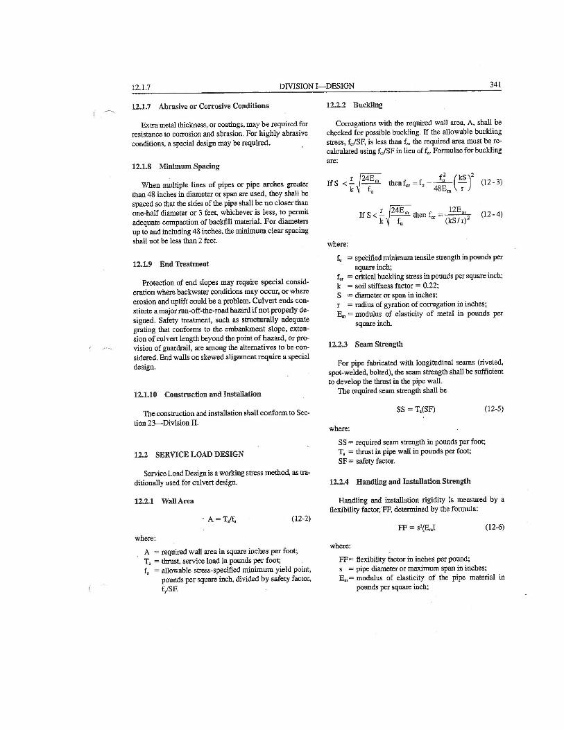
AASHTO Standard Specifications, section no. 12.4 through 12.7 are attached as Appendix I at
the end of Part B guidance.
Part B guidance is applicable to the following structure type:
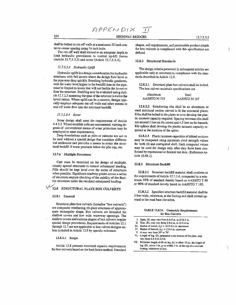
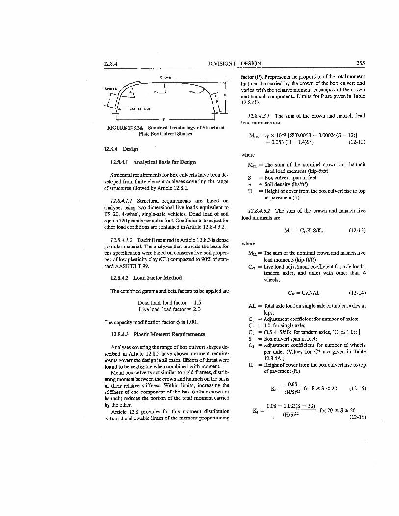
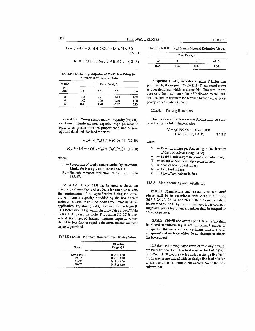
1. Structural Plate Box Culverts as described in AASHTO Standard Specifications, section
no. 12.8.
AASHTO Standard Specifications, section no. 12.8 is attached as Appendix II at the end of
Part B guidance.
Part A Guidance
Use the Existing Bridge Plans and/or Field Measurements to find the following
Structural Dimensions:
1. Find the following structural dimensions as shown in Figure 1:
H1 = Fill Depth at Centerline of Roadway in ft
H2 = Fill Depth at Edge of Pavement in ft
S = Span Length in ft
R = Rise in ft
L = Longitudinal Length of Structure in ft
Rt = Actual Top Radius in ft (See Figure 1 and section 4 for further details)
2. Find the following Metal Corrugation & Gage Information as shown in Figure 1:
Metal Type Steel or Aluminum
Corrugation c (in) = pitch
d (in) = depth
t (in) = thickness of corrugated metal
Pipe Crown Deflection in inches
Metal thicknesses in inches in the most corroded part of the
pipe/structure. Then calculate Φloss = (As inspected X sectional Area in in2 /
Original X sectional Area in in2 ) for 1 ft strip in the longitudinal direction.
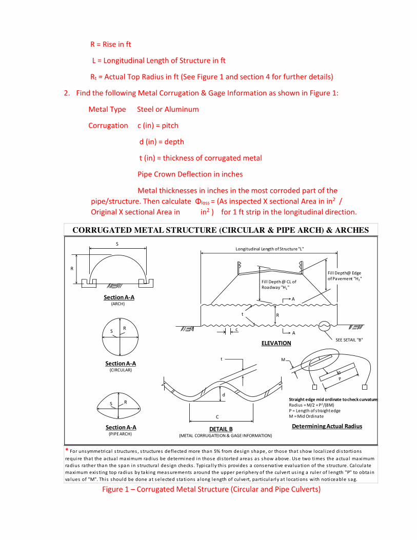
Figure 1 – Corrugated Metal Structure (Circular and Pipe Culverts)
CORRUGATED METAL STRUCTURE (CIRCULAR & PIPE ARCH) & ARCHES
* For unsymmetrica l s tructures , s tructures deflected more than 5% from design shape, or those that show loca l i zed dis tortions
requi re that the actua l maximum radius be determined in thos e dis torted areas as s how above. Us e two times the actua l maximum
radius rather than the span in s tructura l des ign checks. Typica l ly this provides a cons ervative evaluation of the s tructure. Ca lculate
maximum exis ting top radius by taking meas urements around the upper periphery of the culvert us ing a ruler of l ength "P" to obta in
va lues of "M". This should be done at s elected stations a long length of culvert, particul arl y at locations with noticeable s ag.
Longitudinal Length of Structure "L"
Fill Depth @ CL of
Roadway "H1"
c
t
A
A
R
R
S
RS
RS
Section A-A(ARCH)
Section A-A(CIRCULAR)
Section A-A(PIPE ARCH)
SEE SETAIL "B"ELEVATION
DETAIL B(METAL CORRUGATEION & GAGE INFORMATION)
C
d
t
Determining Actual Radius
M
Straight edge mid ordinate to check curvature:
Radius = M/2 + P2/(8M)
P = Length of straight edge
M = Mid Ordinate
Fill Depth@ Edge
of Pavement "H2"
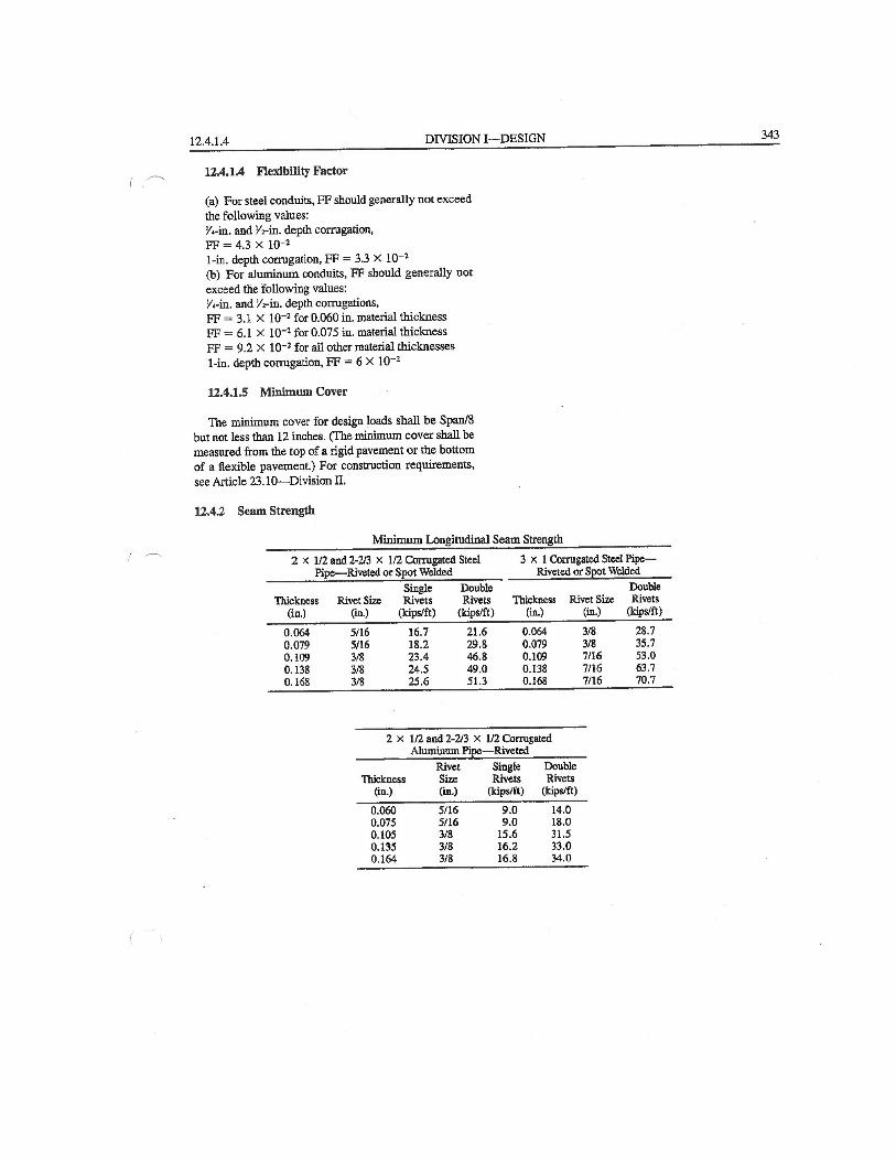
3. Check if the seam type is spot welded, riveted or bolted. If Yes, obtain longitudinal
Seam Strength from Table 1 provided in next page (page no. 4).
4. Categorise the Structure into two categories – Category i) Typical Structure –
Symmetric structures deflected less than or equal to 5% of the diameter of the pipe
from design shape.
or Category ii) Unsymmetrical Structures or Structures deflected over 5% of the
diameter of the pipe from design shape.
For category I, use the actual span as Span S in calculations.
For category ii, a. Determine the top radius Rt as follows: Measure the chord length
at top, P between the point of curve on the vertical leg of the structure to point of
tangency on the horizontal leg of the structure using a ruler (see Figure 1). Measure
the middle ordinate at the upper periphery of the structure, M at the midpoint of
the chord. Then calculate the top radius Rt by the formula, Rt = M/2 + P2/(8M) .
Then Use two times the top radius (2Rt) as Span S for calculations.
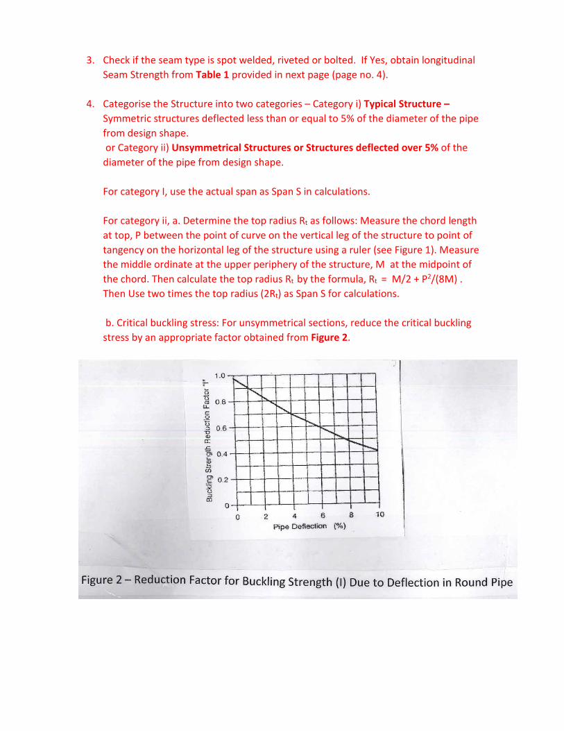
b. Critical buckling stress: For unsymmetrical sections, reduce the critical buckling
stress by an appropriate factor obtained from Figure 2.
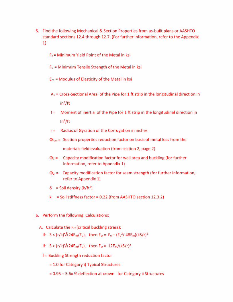
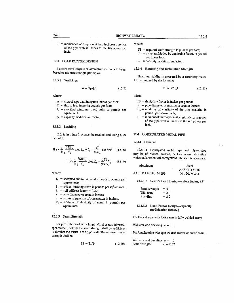
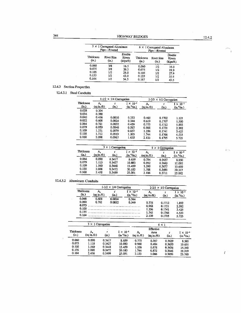
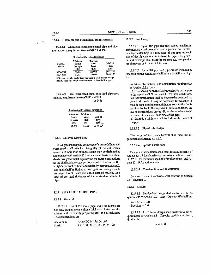
5. Find the following Mechanical & Section Properties from as-built plans or AASHTO
standard sections 12.4 through 12.7. (For further information, refer to the Appendix
1)
FY = Minimum Yield Point of the Metal in ksi
Fu = Minimum Tensile Strength of the Metal in ksi
Em = Modulus of Elasticity of the Metal in ksi
As = Cross-Sectional Area of the Pipe for 1 ft strip in the longitudinal direction in
in2/ft
I = Moment of inertia of the Pipe for 1 ft strip in the longitudinal direction in
In4/ft
r = Radius of Gyration of the Corrugation in inches
Φloss = Section properties reduction factor on basis of metal loss from the
materials field evaluation (from section 2, page 2)
Φ1 = Capacity modification factor for wall area and buckling (for further
information, refer to Appendix 1)
Φ2 = Capacity modification factor for seam strength (for further information,
refer to Appendix 1)
δ = Soil density (k/ft3)
k = Soil stiffness factor = 0.22 (from AASHTO section 12.3.2)
6. Perform the following Calculations:
A. Calculate the Fcr (critical buckling stress):
If: S < (r/k)√(24Em/Fu), then Fcr = Fu – (Fu2/ 48Em)(kS/r)2
If: S > (r/k)√(24Em/Fu), then Fcr = 12Em/(kS/r)2
f = Buckling Strength reduction factor
= 1.0 for Category i) Typical Structures
= 0.95 – 5.6x % deflection at crown for Category ii Structures
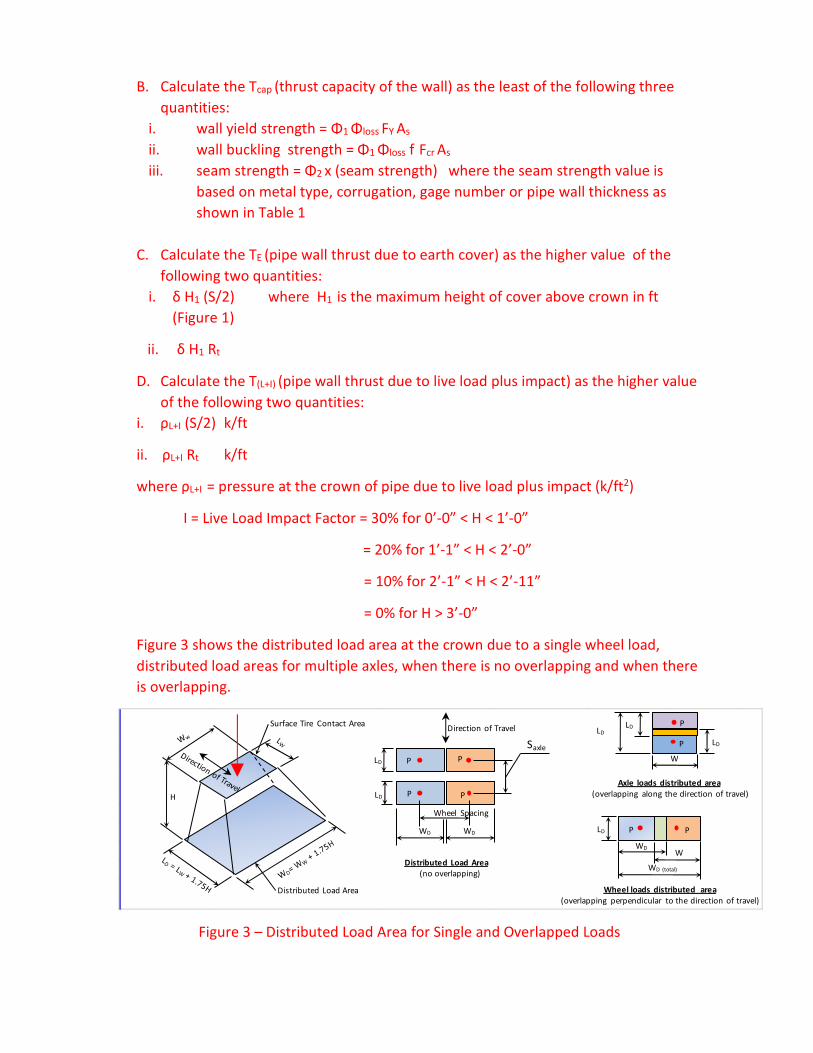
B. Calculate the Tcap (thrust capacity of the wall) as the least of the following three
quantities:
i. wall yield strength = Φ1 Φloss FY As
ii. wall buckling strength = Φ1 Φloss f Fcr As
iii. seam strength = Φ2 x (seam strength) where the seam strength value is
based on metal type, corrugation, gage number or pipe wall thickness as
shown in Table 1
C. Calculate the TE (pipe wall thrust due to earth cover) as the higher value of the
following two quantities:
i. δ H1 (S/2) where H1 is the maximum height of cover above crown in ft
(Figure 1)
ii. δ H1 Rt
D. Calculate the T(L+I) (pipe wall thrust due to live load plus impact) as the higher value
of the following two quantities:
i. ρL+I (S/2) k/ft
ii. ρL+I Rt k/ft
where ρL+I = pressure at the crown of pipe due to live load plus impact (k/ft2)
I = Live Load Impact Factor = 30% for 0’-0” < H < 1’-0”
= 20% for 1’-1” < H < 2’-0”
= 10% for 2’-1” < H < 2’-11”
= 0% for H > 3’-0”
Figure 3 shows the distributed load area at the crown due to a single wheel load,
distributed load areas for multiple axles, when there is no overlapping and when there
is overlapping.
Figure 3 – Distributed Load Area for Single and Overlapped Loads
H
Distributed Load Area
Surface Tire Contact Area
P PLD
WD WD LD
WDW
WD (total)Distributed Load Area
(no overlapping)
Wheel loads distributed area
(overlapping perpendicular to the direction of travel)
P P
P P
Wheel Spacing
LD
SaxleP
PLD
LD
LD
W
P
P
Axle loads distributed area
(overlapping along the direction of travel)
Direction of Travel
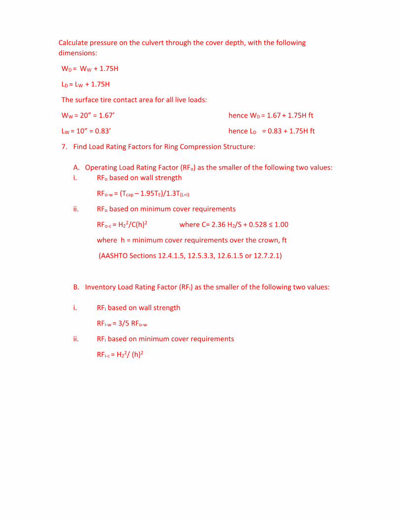
Calculate pressure on the culvert through the cover depth, with the following
dimensions:
WD = WW + 1.75H
LD = LW + 1.75H
The surface tire contact area for all live loads:
WW = 20” = 1.67’ hence WD = 1.67 + 1.75H ft
LW = 10” = 0.83’ hence LD = 0.83 + 1.75H ft
7. Find Load Rating Factors for Ring Compression Structure:
A. Operating Load Rating Factor (RFo) as the smaller of the following two values:
i. RFo based on wall strength
RFo-w = (Tcap – 1.95TE)/1.3T(L+I)
ii. RFo based on minimum cover requirements
RFo-c = H22/C(h)2 where C= 2.36 H2/S + 0.528 ≤ 1.00
where h = minimum cover requirements over the crown, ft
(AASHTO Sections 12.4.1.5, 12.5.3.3, 12.6.1.5 or 12.7.2.1)
B. Inventory Load Rating Factor (RFi) as the smaller of the following two values:
i. RFi based on wall strength
RFi-w = 3/5 RFo-w
ii. RFi based on minimum cover requirements
RFi-c = H22/ (h)2
Part B Guidance
Use the Existing Bridge Plans and/or Field Measurements to find the following
Structural Dimensions:
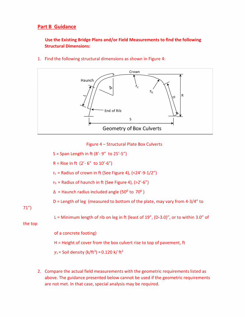
1. Find the following structural dimensions as shown in Figure 4:
Figure 4 – Structural Plate Box Culverts
S = Span Length in ft (8’- 9” to 25’-5”)
R = Rise in ft (2’- 6” to 10’-6”)
rc = Radius of crown in ft (See Figure 4), (<24’-9-1/2”)
rh = Radius of haunch in ft (See Figure 4), (>2’-6”)
Δ = Haunch radius included angle (500 to 700 )
D = Length of leg (measured to bottom of the plate, may vary from 4-3/4” to
71”)
L = Minimum length of rib on leg in ft (least of 19”, (D-3.0)”, or to within 3.0” of
the top
of a concrete footing)
H = Height of cover from the box culvert rise to top of pavement, ft
�s = Soil density (k/ft3) = 0.120 k/ ft3
2. Compare the actual field measurements with the geometric requirements listed as
above. The guidance presented below cannot be used if the geometric requirements
are not met. In that case, special analysis may be required.
S
R
Haunch
Crown
End of Rib
rc
rh
Geometry of Box Culverts
3. Calculate the Box Culvert Moment Capacities at Crown (Mcap (Crown)) in k-ft/ft in the
longitudinal direction of culvert and at Haunch (Mcap (Haunch)) in k-ft/ft in the
longitudinal direction of culvert as follows:
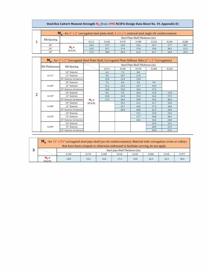
Calculate Mcap (Crown) as the moment capacity of the crown, Mp adjusted for condition
factors as shown in the appropriate table in Appendix III for Steel Box Culverts.
Calculate Mcap (Haunch) as the moment capacity of the haunch Mp adjusted for
condition factors as shown in the appropriate table in Appendix III for Steel Box
Culverts.
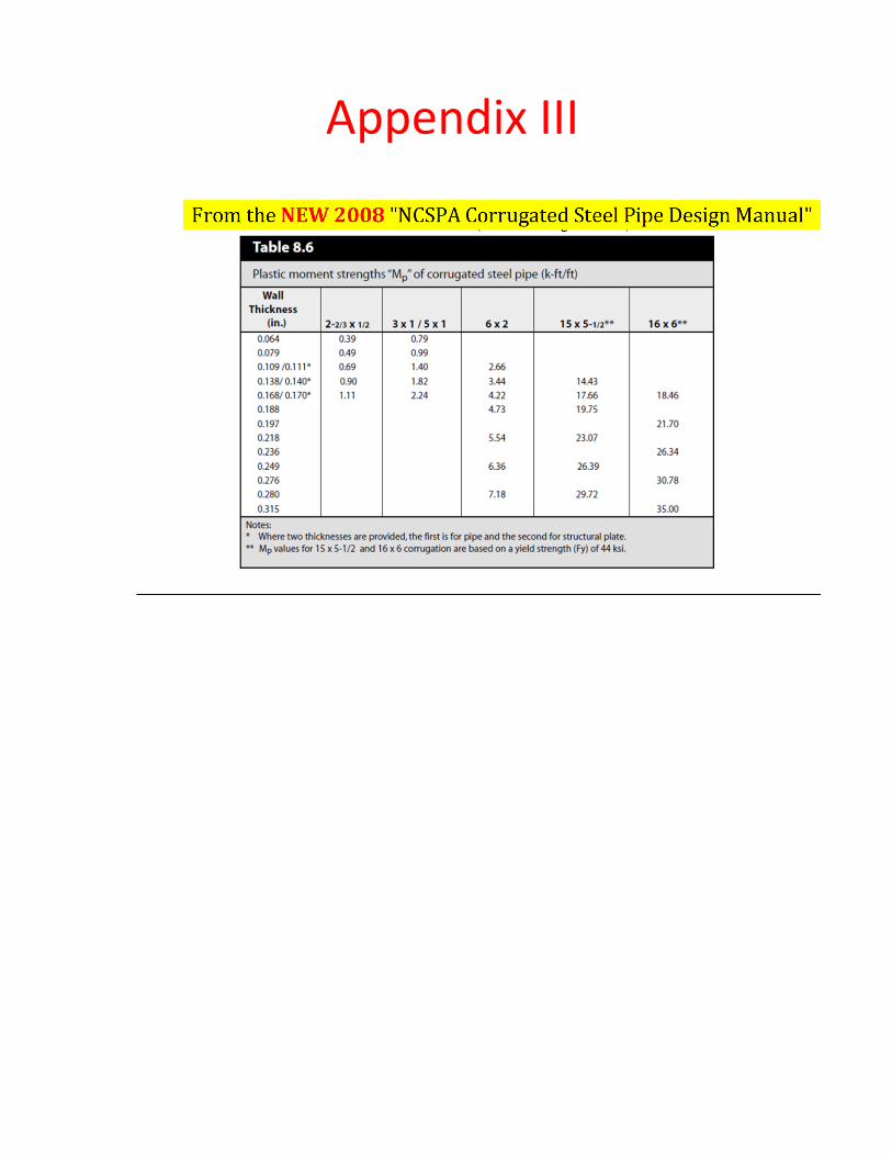
For Aluminum Box Culverts manufactured by CONTECH, see Appendix IV for Mp
values.
For Aluminum Box Culverts manufactured by other manufacturer, please contact the
manufacturer for Mp values. If the manufacturer cannot be contacted or Mp values
cannot be obtained, the load rating may be performed through the use of
engineering judgement as per NJDOT’s guidelines for “Load Capacity Ratings through
Engineering Judgement”.
4. Calculate the Box Culvert Dead Load Moment by the following formula:
MDL = �s {S3 [0.0053 – 0.00024(S – 12)] + 0.053 (H – 1.4) S2}
Where
MDL = The sum of the nominal crown and haunch dead load moments (kip-ft/ft)
Crown Moment due to Dead Load, ME (crown) = Pc CH (MDL) (kip-ft/ft)
Haunch Moment due to Dead Load, ME (haunch) = (1.0 - Pc ) CH (MDL) (kip-ft/ft)
Where,
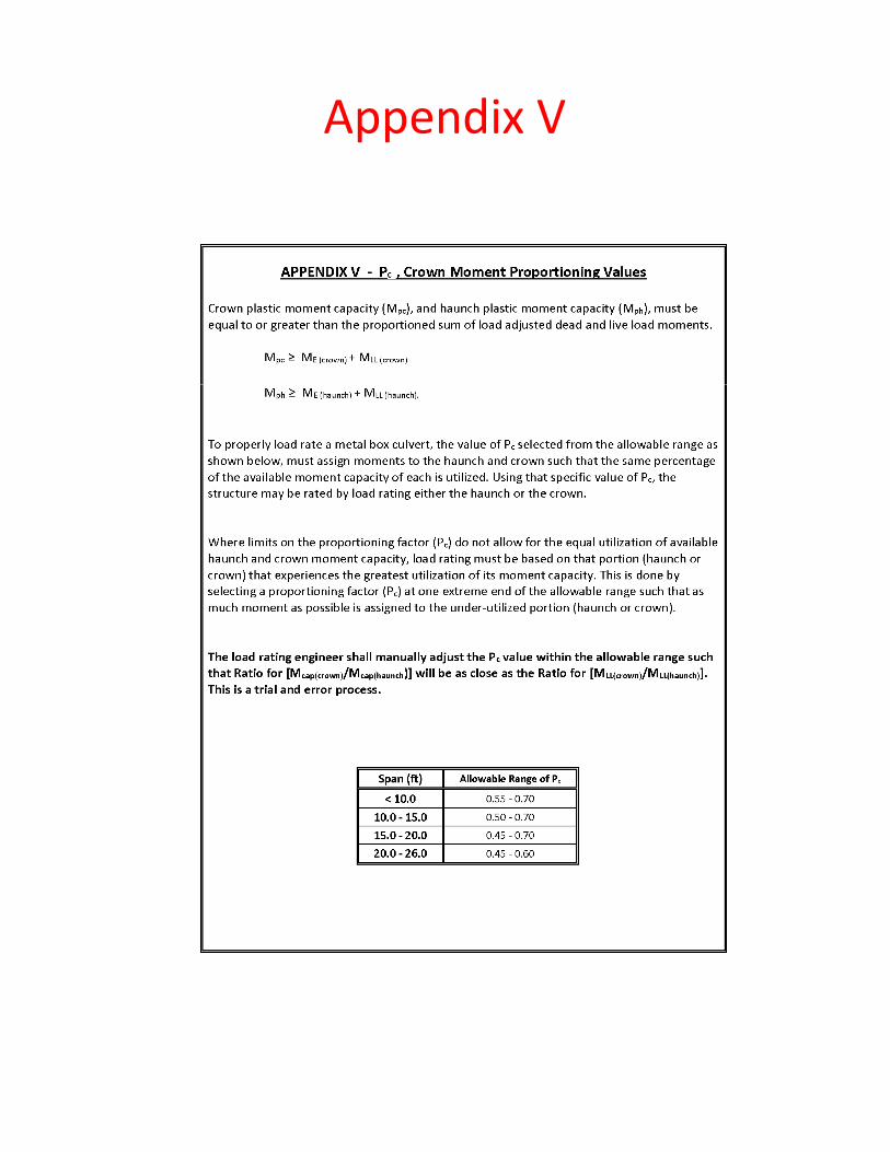
Pc = Allowable range of the ratio of total moment carried by the crown
(See Appendix V how to find proper value for Pc )
CH = Moment increase factor due to crown deflection
= 1.0 for Crown deflection (reduction in rise) less than 1% of span
= 1.15 – (H-1.4)/14 for Crown deflection) of 1 to 3% of span
= Special analysis is required for Crown deflection greater than 3% of
span
5. Calculate the Box Culvert Live Load Moment by the following formula:
MLL = Cll K1 S/ K2 = 0.08/(H/S)0.2 , for 8 < S <20, (kip-ft/ft)
Where
MLL = The sum of the nominal crown and haunch live load moments (kip-ft/ft)
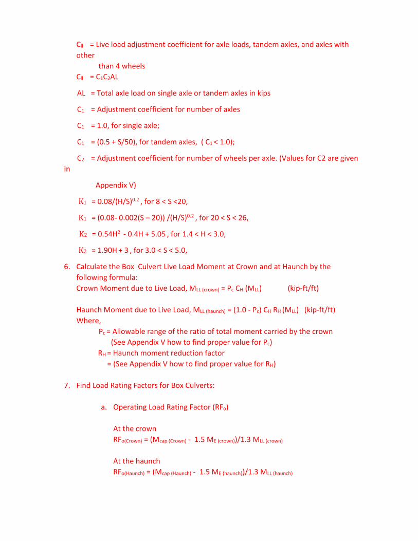
Cll = Live load adjustment coefficient for axle loads, tandem axles, and axles with
other
than 4 wheels
Cll = C1C2AL
AL = Total axle load on single axle or tandem axles in kips
C1 = Adjustment coefficient for number of axles
C1 = 1.0, for single axle;
C1 = (0.5 + S/50), for tandem axles, ( C1 < 1.0);
C2 = Adjustment coefficient for number of wheels per axle. (Values for C2 are given
in
Appendix V)
K1 = 0.08/(H/S)0.2 , for 8 < S <20,
K1 = (0.08- 0.002(S – 20)) /(H/S)0.2 , for 20 < S < 26,
K2 = 0.54H2 - 0.4H + 5.05 , for 1.4 < H < 3.0,
K2 = 1.90H + 3 , for 3.0 < S < 5.0,
6. Calculate the Box Culvert Live Load Moment at Crown and at Haunch by the
following formula:
Crown Moment due to Live Load, MLL (crown) = Pc CH (MLL) (kip-ft/ft)
Haunch Moment due to Live Load, MLL (haunch) = (1.0 - Pc) CH RH (MLL) (kip-ft/ft)
Where,
Pc = Allowable range of the ratio of total moment carried by the crown
(See Appendix V how to find proper value for Pc)
RH = Haunch moment reduction factor
= (See Appendix V how to find proper value for RH)
7. Find Load Rating Factors for Box Culverts:
a. Operating Load Rating Factor (RFo)
At the crown
RFo(Crown) = (Mcap (Crown) - 1.5 ME (crown))/1.3 MLL (crown)
At the haunch
RFo(Haunch) = (Mcap (Haunch) - 1.5 ME (haunch))/1.3 MLL (haunch)

The lower among the above two values is the operating load Rating Factor
(RFo) for the culvert.
b. Inventory Load Rating Factor (RFi) is given by:
RFi = 3/5 RFo

Appendices
Appendix III
0.111 0.140 0.170 0.188 0.218 0.249 0.280
30" 12.4 13.7 14.9 15.6 16.7 17.7 18.7
24" 14.2 15.7 17.0 17.8 19.0 20.2 21.3
18" 17.2 18.8 20.4 21.4 22.7 24.0 25.3
0.111 0.140 0.170 0.188 0.218
24" Exterior 6.4 7.3 8.0
12" Exterior 9.4 10.7 11.9
24" Exterior & Interior 12.0 12.9 13.8
24" Exterior 7.4 8.4 9.2 9.9
12" Exterior 11.1 12.5 13.7 14.5
24" Exterior & Interior 14.6 15.6 16.6 17.2
24" Exterior 8.3 9.5 10.4 11.0 11.8
12" Exterior 12.0 14.4 15.2 16.2 17.5
24" Exterior & Interior 17.5 18.3 19.0 19.5 20.3
24" Exterior 10.1 11.1 11.7 12.6
12" Exterior 14.7 16.2 17.2 18.6
24" Exterior & Interior 20.0 20.8 21.3 22.0
24" Exterior 12.1 12.8 14.2
12" Exterior 17.7 18.8 20.2
24" Exterior & Interior 23.6 24.0 24.8
24" Exterior 13.9 15.1
12" Exterior 20.0 21.9
24" Exterior & Interior 26.8 27.6
Steel Box Culvert Moment Strength Mp (from 1995 NCSPA Design Data Sheet No. 19, Appendix D)
0.170"
0.188"
0.218"
0.111"
Steel Plate Shell Thickness (in)
Mp - for 6" x 2" Corrugated Steel Plate Shell, Corrugated Plate Stiffener Ribs (6" x 3" Corrugation)
0.140"
Rib Spacing
1Steel Plate Shell Thickness (in)
Mp - for 6" x 2" corrugated steel plate shell, 5 x 3 x ½ external steel angle rib reinforcements
Mp =
(ft-k/ft)
Rib Thicknesses
Rib Spacing
0.249"
2
Mp =
(ft-k/ft)
0.140 0.170 0.188 0.218 0.249 0.280 0.318 0.377
Mp =
(ft-k/ft)10.8 13.2 14.8 17.3 19.8 22.3 25.3 30.4
3
Mp - for 15" x 5½" corrugated steel pipe shell (no rib reinforcements); Material with corrugation crests or valleys
that have been crimped or otherwise embossed to facilitate curving, do not apply
Steel pipe Shell Thickness (in)
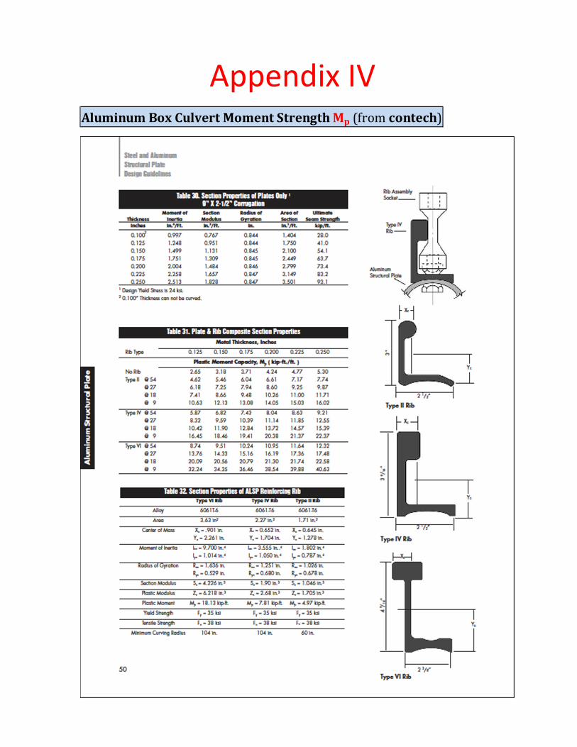
Appendix IV
Aluminum Box Culvert Moment Strength Mp (from contech)
Appendix V

Appendix VI Appendix VI – AASHTO Standard Specification Values for C2 and Rh
Cover Depth, ft C2 (2 wheels/axle ) C2 (4 wheels/axle ) C2 (8 wheels/axle ) Rh Value (AASHTO Table 12.8.4C)
< 1.4
1.400 1.180 1.000 0.630 0.660
1.550 1.188 1.000 0.648 0.680
1.700 1.195 1.000 0.665 0.700
1.850 1.203 1.000 0.683 0.720
2.000 1.210 1.000 0.700 0.740
2.250 1.218 1.000 0.730 0.773
2.500 1.225 1.000 0.760 0.805
2.750 1.233 1.000 0.790 0.838
3.000 1.240 1.000 0.820 0.870
3.500 1.185 1.000 0.848 0.935
4.000 1.130 1.000 0.875 1.000
4.500 1.075 1.000 0.903 1.000
5.000 1.020 1.000 0.930 1.000
Number of Wheels per Axle Adjustment Coefficient, C2 (AASHTO LRFD Table 12.9.4.2-1), and Haunch Moment Reduction Factor, Rh (AASHTO LRFD Table 12.9.4.3-2)