guide specifications for security metal ceilings · part 1 of this specification references astm...
TRANSCRIPT
DEMA 111970 - 12
GUIDE SPECIFICATIONS
FOR SECURITY METAL CEILINGS
DEM
A 11
1970
-12
12 D
ETEN
TIO
N E
QU
IPM
ENT
12 D
EMA 111970-12
DETEN
TION
EQU
IPMEN
T Septem
ber, 2012
A Division of
NATIONAL ASSOCIATION OF ARCHITECTURAL METAL MANUFACTURERS
NAAMM STANDARD
Sept
embe
r, 20
12
DETENTION EQUIPMENT
MANUAL

This standard was developed by representative members of the Detention Equipment Manufacturers Association (DEMA) a Division of the National Association of Architectural Metal Manufacturers (NAAMM) to provide their opinion and guidance on the specification and use of detention equipment. This standard contains advisory information only and is published as a public service by NAAMM and its DEMA Division.
NAAMM and its DEMA Division disclaim all liability of any kind for the use, application, or adaptation of material published in this standard.
Current information on all NAAMM Standards is available by calling, writing or visiting the website of the National Association of Architectural Metal Manufacturers, www.naamm.org.
National Association of Architectural Metal Manufacturers 800 Roosevelt Road, Bldg. C, Suite 312
Glen Ellyn, Illinois 60137 Tel: 1-630-942-6591 Fax: 1-630-790-3095
E-mail: [email protected] Website: www.naamm.org
Copyright © 2012 National Association of Architectural Metal Manufacturers
All Rights Reserved

TABLE OF CONTENTS
Forward ........................................................................................................................................................ ii
Part 1 – General ................................................................................................................................. 1
1.01 Summary ................................................................................................................................... 1
1.02 Products Provided Under This Section ...................................................................................... 1
1.03 Related Sections ........................................................................................................................ 1
1.04 References ................................................................................................................................ 1
1.05 Testing and Performance .......................................................................................................... 2
1.06 Quality Assurance ...................................................................................................................... 6
1.07 Submittals ................................................................................................................................... 7
Part 2 – Products ................................................................................................................................ 7
2.01 Designs ..................................................................................................................................... 7
Part 3 – Execution ............................................................................................................................ 10
3.01 Delivery, Storage and Handling ............................................................................................... 10
3.02 Installation ............................................................................................................................... 10
3.03 Field Quality Control ................................................................................................................ 11

FORWARD
________________________________________________________________________
These Specifications have been prepared to align with the CSI recommended format with Part 1 – General, Part 2 – Product, and Part 3 – Execution. Explanatory notes or instructions are shown in italics. Guide specifications are intended to be used as the basis for developing job specifications, and must be edited to fit specific job requirements. Inapplicable provisions should be deleted, appropriate selections should be made where there are choices, and provisions applicable to the job should be added where necessary. Optional items or requirements are shown in brackets. Notes and instructions to specifiers are given in italics directly following, or at the start of the paragraphs to which they apply. Notes that contain permissive language are not considered part of the standard. Dates provided with ASTM and other standards were current at the time this specification was published; when a more recent standard is available, the specifier should verify its applicability to this Guide prior to its inclusion.
Part 1 of this specification references ANSI/SDI A250.3 and ANSI/SDI A250.10 for prime paint and finish coating. These standards capture all of the pertinent ASTM testing requirements for applying primers and finish coats to sheet metal substrates, and provide the specifier with condensed references, and those items of importance when applying coatings to architectural sheet metals.
Part 1 of this specification references ASTM work item Wk 9092 Standard Test Methods for Physical Assault on Overhead Horizontal Fixed Barriers for Detention and Correctional Facilities. Table 1: Security Grades and Load Requirements for Ceiling Panels depicts the different grades for ceiling panels. It is important that the specifier selects the correct Grade Number for the application, understanding the difference between the hollow metal panel type ceiling (Grades 1 & 2) and the single sheet panel ceilings (Grades 3 & 4), to ensure proper application of the specification.
Materials and fabrication methods are specified in detail in Part 2. However, the materials and fabrication methods defined in these specifications, while providing a sound guide, are not meant to restrict the use of other materials and methods, where it can be demonstrated through the specific testing procedures in Section 1.05 that the construction can equal or exceed the performance levels specified in this section. In order to ensure that a manufacturer’s product meets the desired performance levels, the project specifications shall include the testing and performance requirements of Section 1.05, and the Quality Assurance requirements of section 1.06

Security Metal Ceilings NAAMM DEMA 11 19 70
1
Detention Metal Ceilings
PART 1 - GENERAL 1.01 SUMMARY A. Section includes Detention acoustical and non-acoustical plank metal ceilings, including
installation as scheduled in the contract drawings and as specified herein. 1.02 PRODUCTS PROVIDED UNDER THIS SECTION
A. Medium [Grades 3 & 4] detention single skin plank type acoustical and non-acoustical ceiling systems.
B. Maximum [Grades 1 & 2] detention double skin plank type acoustical and non-acoustical ceiling systems.
1.03 RELATED SECTIONS A. Section 09900 Painting B. Division 11 Detention Equipment C. Division 15 Mechanical D. Division 16 Electrical 1.04 REFERENCES
A. ASTM A 1008/A 1008M-09, Specification for Steel, Sheet and Strip, Cold-Rolled, Carbon, Structural, High-Strength Low-Alloy, and High-Strength Low-Alloy with Improved Formability, Solution Hardened and Bake Hardenable.
B. ASTM A 1011/A 1011M-09b, Specification for Steel, Sheet and Strip, Hot-Rolled, Carbon,
Structural, High-Strength Low-Alloy, and High-Strength Low-Alloy with Improved Formability
C. ASTM A 653/A 653M-09a, Specification for Steel Sheet, Zinc-coated (Galvanized) or Zinc-Iron Alloy Coated (Galvanealed) by the Hot Dipped Process (Commercial Steel)
D. ASTM A 666-03, Standard Specification for Annealed or Cold-Worked Austenitic Stainless Steel
Sheet, Strip, Plate and Flat Bar E. ANSI/SDI A250.3-2007 (R2011) Test Procedure and Acceptance Criteria for Factory Applied
Finish Coatings for Steel Doors and Frames. F. ANSI/SDI A250.10-1998 (R2011) Test Procedure and Acceptance criteria for Prime Painted Steel
Surfaces for Steel Doors and Frames.
G. ASTM C 635/C 635M-08, Standard Specification for the Manufacture, Performance and Testing of Metal Suspension Systems for Acoustical Tile and Lay-in Panel Ceilings.
H. ASTM C 636/C 636M-08, Standard Practice for Installation of Metal Ceiling Suspension Systems
for Acoustical Tile and Lay-In Panels
I. ASTM C 423-09a, Standard Test Method for Sound Absorption and Sound Absorption Coefficient by the Reverberation Room Method
J. ASTM F 2322-03 Standard Test Methods for Physical Assault on Vertical Fixed Barriers for
Detention and Correctional Facilities

Security Metal Ceilings NAAMM DEMA 11 19 70
2
K. ASTM Wk 9092 (work item) Standard Test Methods for Physical Assault on Overhead Horizontal
Fixed Barriers for Detention and Correctional Facilities L. ASTM E-84-10, Standard Test Method for Surface Burning Characteristics of Building Materials.
M. AWS D1.3 Structural Welding Code for Sheet Metal
N. ISO 9000 International Standards Organization – Standards for Quality Management O. CISCA Guidelines Abbreviations: 1. DEC: Detention Equipment Contractor 2. ASTM: American Society for Testing Materials 3. AWS: American Welding Society 4. CISCA: Ceilings and Interior Systems Construction Association 1.05 TESTING AND PERFORMANCE
A. Security grades for each security ceiling type shall be indicated on the reflected ceiling plan.
B. Acoustical Performance
1. Single skin plank ceiling system shall provide a NRC of not less than .90 when tested in
accordance with ASTM C 423. 2. Double skin plank ceiling system shall provide a NRC of not less than .65 when tested in
accordance with ASTM C 423. 3. Acoustical fill flame spread index shall not exceed 15 with smoke developed value not
exceeding 5 when tested in accordance with ASTM C 84.
C. Security Performance
These test methods are not to provide a measure of resistance for ceiling assemblies subjected to attack by corrosive agents. These test methods are intended to evaluate physical attack and simulated forced exit resistance of a ceiling assembly to attack using battering devices and static loading. The primary purpose of these test methods is to approximate the levels of abuse to which ceiling assemblies may be subjected in the course of a forced exit in a correctional facility. The desired result of its use is to help provide insurance of protection and safety of the inhabitants or occupants of the facility where these ceiling assemblies will ultimately be used. It is recommended that architects and building design personnel decide which security rating is required for each opening as described in Table 1.
D. Test Samples
1. A ceiling assembly covering an 8'-0" (2438 mm)x 8'-0" (2438 mm) area using the desired ceiling panel system, shall be constructed in accordance with Part 2 of this specification and installed in accordance with the manufacturer’s instructions.
2. The manufacturer shall permanently mark the test samples and retain them at the
manufacturing facility for future reference for a period of one (1) year from the date tested. All tests will be verified using an independent agency. Test reports shall include photographs of the testing apparatus and installation instructions including templates for the items of hardware used.

Security Metal Ceilings NAAMM DEMA 11 19 70
3
E. Specimen Preparation
1. The construction and size of the test ceiling assemblies consisting of single or double skin
ceiling panels, wall mounting channels and angles, compression struts, hangers, and fasteners, shall be representative of the application under investigation and the desired security classification needed for the application. The same basic construction and size of test assemblies shall apply to all tests.
2. The test assembly shall be installed in a fixture designed and constructed per ASTM Wk
9092 (Work Item – wk 9092) Fig. 1. The fixture shall simulate the rigidity normally provided to a ceiling system in a building by the roof, floor and walls, and shall be constructed in a manner that will not contribute to the deflection of the ceiling assembly when under static loading or impact loading. Figure 1 shows an acceptable fixture.
3. Mount the ceiling assembly under test in the rough opening in accordance with the manufacturer’s installation instructions.
F. Procedures
1. Ceiling Assembly Impact Testing
a. Impact testing under this section is performed using the methods and testing equipment described in ASTM Wk 9092 (Work Item –wk 9092).
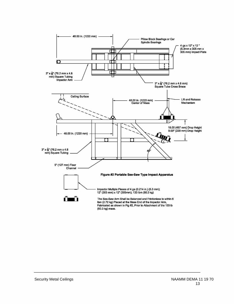
b. Scope: These tests are designed to evaluate the capability of a complete ceiling assembly to resist repetitive impact forces at the designated critical areas. The same assembly used for the static load tests may be reused for this test, or another assembly may be used if so desired. c. Significance of use: This test method is intended to help ensure that detention security ceilings perform at or above minimum acceptable levels for control of passage, and provide an evaluation of the assembly’s capability to prevent, delay and frustrate forcible egress. d. Apparatus: The test fixture described in paragraph 1.05.D. and shown in Figure 1 shall be used in this test.
1. The impact test device (Figure 2) shall consist of a portable see-saw type impactor, which upon release will deliver impacts against the test ceiling. The impact test device will be manufactured in accordance with ASTM Wk 9092 (Work Item – wk-9092)
e. Procedure: Subject each location on the sample ceiling to the number of blows at the required impact energy found in Table 1 and Figure 2. Both the blunt and sharp impactors shall deliver the required impacts at the specified foot pounds per impact. Repeatability of impact location during each series shall be no more than +/- 2 in. (50 mm) horizontally from the designated impact target. Testing shall take no longer than 60 minutes. f. The ceiling must remain in place throughout the testing procedure. Failure is constituted by the ceiling being damaged to the extent that forcible egress can be achieved, or to the extent that the impact test cannot be continued in a practical manner.
2. Ceiling Assembly Static Load Testing (uplift)

Security Metal Ceilings NAAMM DEMA 11 19 70
4
a. Scope: This test is designed to evaluate the capability of a ceiling assembly to resist a steadily increasing force applied to a small area, concentrated at the ceiling assembly central point. b. Significance of Use: This test method is intended to simulate a ceiling assembly’s resistance to uplift at vulnerable locations, with the intent to damage, dislodge or break through the ceiling. c. Apparatus: The test fixture and ceiling described in paragraph 1.05.D and figure 2 shall be used in this test.
1. A hydraulic ram and pump equipped with a gauge or load cell shall be used to provide the static load. The pump ram and gauge shall be calibrated by the testing laboratory and a chart provided that converts pounds-force per square-inch gauge (kilograms per square meter) to pounds-force (Newton’s). If a load cell is used, it shall be certified by the testing laboratory prior to use. (see figure 3 Static Load Apparatus)
d. Procedure: Apply static load to the attack side of the component at the locations and
magnitude appropriate to the security rating desired in accordance with that specified in Table 1. Specimen fails when the desired load cannot be achieved without physical failure or the ability for egress.
e. Record the pass / fail results at 500 lb. increments to produce a graph, static load
versus deflection. Increase the load until target loads for each sample are reached. After reaching maximum required load and recording maximum deflection (0.50” in. (12.7 mm) max., release the load, measure and document the permanent deflection 0.13” in. (3.3 mm) max., within one minute.

Security Metal Ceilings NAAMM DEMA 11 19 70
5
Table 1: Security Grades and Load Requirements for Ceiling Panels
Grade Number
Recommended Ceiling Panel Face Sheet Thickness A
in. (mm) gauge
B Number of Impacts at Each Target Location (total/time)
Static Load lbf (N)
1 0.093 (2.3) 12 Hollow Metal Panel 600 (2400/4 hrs.) 3000 (13 345)
2 0.067 (2.3) 14 Hollow Metal Panel 400 (1600/2 hrs. 40 min.) 2000 (8896)
3 0.093 (1.7) 12 Single Sheet Pan 200 (800/1 hr. 20 min.) 1000 (4448)
4 0.067 (1.7) 14 Single Sheet Pan 100 (400/40 min.) 750 (3336)
Target Locations for Ceiling Impact Test and Ceiling Static Load Test
Location Number
Target Location
1
c
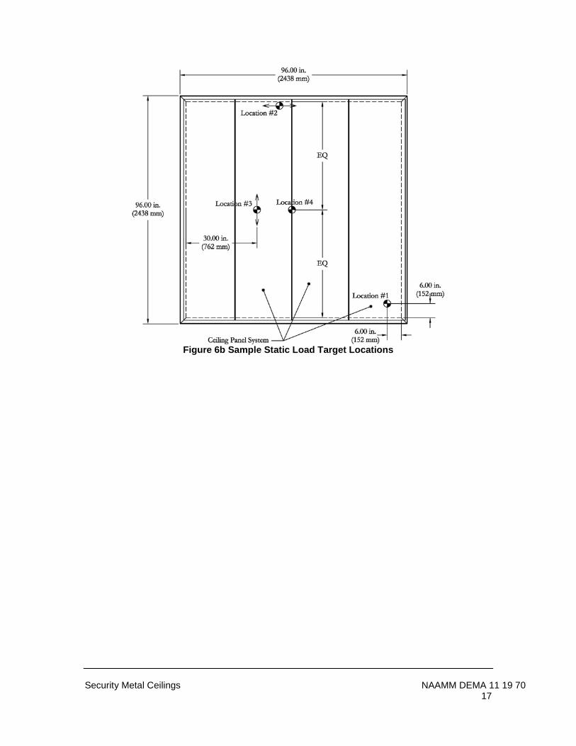
Static Load & Impact: Against the ceiling, within 6 in. (152 mm) of a corner selected by the lab test director
(Figure 6).
2 Static Load & Impact: Against the ceiling along one length of the ceiling wall attachment within 1” (25.4 mm) of the attachment of the wall and the ceiling panel selected by the lab
test director. (Figure 6).
3 Static Load & Impact: Against the ceiling at a distance of 30 in. (762 mm) from the attachment between the ceiling and the test fixture (wall attachment) selected by the lab test
director. (Figure 6).
4 Static Load & Impact: Against the ceiling directly against a seam at or near center span of the seam selected by lab test director. (Figure 6).
5 Static load only: In the seam between the test fixture and ceiling wall anchor at a location selected by the lab test director using the “Pry Test Adapter” (Figure 7).
6 Static load only: Gap at a present horizontal seam (Figure 7).
7 Static load only: In the seam in the middle of ceiling selected by test director 24 in away from edge (Figure 7).
A Grades 1 and 2 shall be identified as a containment ceiling. Grades 3 and 4 shall be identified as a concealment ceiling.
B Alternate materials and methods of construction that promote product innovation including non-metallic and/or square panel ceilings, which meet the aforementioned performance criteria
shall be permitted. c
Impact locations and static load locations may be selected by the lab test director such that no two test locations are within 12 inches (305 mm) of each other.
1.06 QUALITY ASSURANCE
A. Manufacturer's Qualification
1. Manufacturer shall provide evidence of having personnel and plant equipment capable of fabricating ceiling assemblies of the type specified herein. Manufacturer shall provide current documentation of the number of employees, a listing of their production equipment, and a description of their manufacturing

Security Metal Ceilings NAAMM DEMA 11 19 70
6
facility. 2. Manufacturers shall be ISO 9001:2008 certified, or provide evidence of a current
and active written quality system. Quality system documents shall provide evidence of periodic review and revision. Manufacturer shall provide certified test data and production samples as requested. Production material shall be of same design and construction as provided samples.
3. Manufacturer’s production welders shall be qualified under AWS D1.3 and upon
request shall provide copies of Welders Qualifications in accordance with AWS D1.3.
4. Manufacturers shall have written test reports, and documentation by an independent testing agency of their having passed the testing requirements of section 1.05, using their current materials and production processes.
B. Subcontractor (DEC) qualifications 1. Refer to qualifications in section 11 19 00 2. Technically qualified and experienced in furnishing and installing detention
acoustical panels. 3. Welders and tackers shall be qualified by the American Welding Society’s
procedure. AWS D1.3 4. Direct distributor or dealer for the manufacturer of detention acoustical panel
system specified or approved. 5. Submit evidence of prior experience in the installation of metal security ceiling
systems.
C. Quality Criteria
1. All ceiling construction shall be in accordance with construction of assemblies, which meet the testing requirements of Section 1.05.
2. Fabrication methods and product quality shall meet standards specified herein. 3. Job Site Check
At the owner's option, a ceiling panel at the job site shall be selected at random and sawed in half or otherwise taken apart as deemed necessary, for verification that construction is in accordance with these specifications. The manufacturer shall include the cost of the replacement panel in their quotation. If the panel construction does not conform to these specifications the non-conforming panels shall be repaired or replaced at the manufacturer's expense.
1.07 SUBMITTALS
A. Submittal Drawings 1. Submit in accordance with Division 1.

Security Metal Ceilings NAAMM DEMA 11 19 70
7
2. Provide detailed drawings including: layout of ceiling systems, details of Construction, gauges of metal, anchoring details, conditions at openings, Installation details and methods, and other data pertinent to the installation, including illustration of sequence of installation to accomplish interlocking panels. 3. Do not begin fabrication of material until shop drawings have been reviewed and approved by the architect.
B. Samples (if required)
1. Supply a 1'-0” (304.8) x 1'-0" (304.8) section of each ceiling system being supplied showing wall mounting members and panel sections.
2. All samples submitted shall be of the production type and shall represent in all
respects the minimum quality of work to be furnished by the manufacturer. No work represented by the samples shall be fabricated until the samples are approved, and any downgrading of quality demonstrated by the samples can be cause for rejection of the work.
C. Products other than those specified or approved will be considered if the following items are submitted to the Architect at least 10 days prior to bid due date.
a. Physical samples. b. Catalog and technical information c. References (including name and telephone number or person to contact) d. Notarized certification that the product conforms to the requirements, quality, and durability of the products specified herein. e. If a substitution is approved, it will be in the form of an addendum to the bidding documents.
PART 2 - PRODUCTS 2.01 DESIGNS A. PRE-APPROVED ACCEPTABLE MANUFACTURERS
1. Security Grade 1: 0.093 (2.3) 12 ga. Double skin rabbeted edge plank ceiling systems as manufactured by:
2. Security Grade 2: 0.67 (1.7) 14 ga. Double skin rabbeted edge plank ceiling systems
as manufactured by: 3. Security Grade 3: 0.093 (2.3) 12 ga. Single skin interlocking plank ceiling systems as
manufactured by: 4. Security Grade 4: 0.067 (1.7) 14 ga. Single skin interlocking plank ceiling systems as
manufactured by:
B. MATERIAL

Security Metal Ceilings NAAMM DEMA 11 19 70
8
1. Panel face sheets shall be made of commercial quality, level, cold-rolled steel conforming to ASTM A 1008 / A 1008M CS Type B and shall have a zinc coating applied by the hot-dip process conforming to ASTM A 653/A653M Commercial Steel (CS), coating designation A60. The steel shall be free of scale, pitting, coil breaks or other surface blemishes. It shall also be free of buckles, waves or any other defects caused by the use of improperly leveled sheets.
2. Severely corrosive conditions and where specified face sheets and components shall be
stainless steel conforming to ASTM A 666, Type 304. C. CONSTRUCTION – SINGLE SKIN PLANK CEILING SYSTEMS
1. Single Skin inter-locking plank ceiling system – Security Grades 3 and 4
a. Ceiling planks: Shall be 24 inch (609.6) wide and supplied in manufacture’s standard lengths of 8 ft. (2438.4), 10 ft. (3048), and 12 ft. (3657.6) All ceiling planks shall have factory formed inter-locking edges. Panels shall be perforated with 0.125 inch (3.1) diameter holes, staggered .218 inch (5.5) on center for a 29% open area for acoustical applications.
b. Wall perimeter angles: Shall be formed angles 0.093 inch (2.3) minimum thickness and punched 4 inch (101.6) on center for .375 inch (9.5) expansion anchors. Panels shall be secured to the wall angles using .093 inch (2.3) 12 ga. concealed angle clips.
c. Interim Tee supports: Tee supports shall be two wall mounting angles bolted back to back using 3/8 – 16 bolts, 24 inches (609.6) on center.
1. Suspension for Tee supports shall be .375 inch (9.5) galvanized threaded rod, fastened to the above structure and the Tee support, 36 inches (914.4) on center.
d. Fasteners: Any exposed fasteners shall be a minimum No.10 size, pin Torx®, tamper-proof security screws or blind rivets. Wall anchor bolts shall be .375 inch (9.5) in diameter, expansion anchors and shall be placed 16 inches (406.4) on center. Anchors for securing the wall moldings to the wall shall be furnished by the installing contractor. For application with metal wall systems, the ceiling manufacturer shall provide weld details.
e. Acoustical material. Where specified, the inside surface of all perforated ceiling pans shall be covered with a Class “A” poly-encapsulated fiberglass insulation of sufficient thickness and density to provide the acoustical requirements as outlined in Section 1.05 of this specification.
f. Lights, HVAC: All light and air units are to be sized to fit into and trim off full module width openings and shall be independently supported from above by the trade requiring the opening.
g. Finish: All components of the panel and suspension system visible from the floor side shall have a factory applied finish, applied to meet ANSI/SDI A250.3 Test Procedure and Acceptance Criteria for Factory Applied Finish Coatings. Prior to painting, all surfaces shall be cleaned of rust, oil and other impurities by receiving a multi stage pre treatment consisting of degrease and phosphate coating, clear water rinse and non-chromate sealer and rinse, to condition the surface of the metal to resist and inhibit corrosion and promote paint adhesion. Finish to be applied after perforation to insure coating of the perforated holes. Panels and components shall be coated with baked powder coat, applied per powder coat manufacturer’s recommendation.

Security Metal Ceilings NAAMM DEMA 11 19 70
9
D. CONSTRUCTION – DOUBLE SINGLE SKIN PLANK CEILING SYSTEMS 1. Double Skin Rabbeted Edge Plank Ceiling System – Security Grades – 1 and 2
a. Ceiling panels: Shall be 24 inch (609.6) wide and supplied in manufacture’s standard lengths of 6 ft, (1828.8) 8 ft. (2438.4) or 10 ft. (3048). All ceiling planks shall have factory formed ship-lap edges. If acoustical performance is required, panels shall be perforated with 0.125 inch (3.1) diameter holes, staggered .218 inch (5.5) on center for a 29% open area for acoustical applications.
b. Panel core construction: Panels shall be stiffened using one of the follow core
systems. 1. Continuous steel truss design core material, .015 inch (.38) minimum, having
truncated triangular sections extending continuously from one panel face to the other, spot welded to each face sheet 2.75 inch (69.8) on center horizontally and 3 inch (76.2) on center vertically. Core material shall extend full height and width of panel.
2. Continuous vertical hat sections, one such hat section welded to each face of the
panel, .041 inch (1.04) minimum thickness. Hat sections shall be welded to each other at least 16 inch (406.4) on center both sides in order to prevent separation.
3. Alternate stiffening systems that pass all required performance tests may be
utilized. 4. Spaces between stiffeners shall be filled with fiberglass or mineral rock wool batt-
type material. c. Start and Ending Panels: shall be 0.093 inch (2.3) minimum thickness, single skinned
non-perforated material and shall be cut to size in the field by the installing contractor.
d. Wall perimeter angles: Shall be formed angles 0.093 inch (2.3) minimum thickness and punched 4 inch (101.6) on center for .500 inch (12.7) in. expansion anchors or welding to metal wall systems. Panels shall be welded to the wall angles 1 inch (25.4) weld 12 inches (304.8) on center.
e. Interim Tee supports: Tee supports shall be two wall mounting angles bolted back to
back using 3/8 – 16 bolts, 24 inches (609.6) on center.
1. Suspension for Tee supports shall be .375 inch (9.5) galvanized threaded rod, fastened to the above structure and the Tee support, 36 inches (914.4 mm) on center.
f. Fasteners: Any exposed fasteners shall be a minimum No.10 size, pin Torx®, tamper-proof security screws or blind rivets. Wall anchor bolts shall be .500 inch (12.7) diameter, expansion anchors and shall be placed 16 inches (406.4) on center. Anchors for securing the wall moldings to the wall shall be furnished by the installing contractor. For application with metal wall systems, the ceiling manufacturer shall provide weld details.

Security Metal Ceilings NAAMM DEMA 11 19 70
10
g. Acoustical material: Where specified, the inside surface of all double skin perforated ceiling pans shall be filled with mineral wool insulation of sufficient thickness and density to provide the acoustical requirements as outlined in Section 1.05 of this specification.
h. Lights, HVAC: All light and air units are to be sized to fit into and trim off full module width openings and shall be independently supported from above by the trade requiring the opening.
i. Finish: All components of the panel and suspension system visible from the floor side shall have a factory applied prime finish, applied to meet ANSI/SDI A250.10 Test Procedure and Acceptance Criteria for Prime Painted Steel Surfaces. Prior to painting, all surfaces shall be cleaned of rust, oil and other impurities by receiving a multi stage pre treatment consisting of degrease and phosphate coating, clear water rinse and non-chromate sealer and rinse, to condition the surface of the metal to resist and inhibit corrosion and promote paint adhesion. Prime finish to be applied per manufacturer’s recommendation; and after perforation to insure coating of the perforated holes. Where finish coating is required, coating shall be applied per ANSI/SDI A250.3 Test Procedure and Acceptance Criteria for Factory Applied Finish Coatings.
PART 3 - EXECUTION 3.01 DELIVERY, STORAGE AND HANDLING A. Protect panels from damage during transit to job storage.
B. Inspect panels upon delivery for damage. Minor damage may be repaired provided finish items are equal in respect to new work and acceptable to Architect/Engineer. Otherwise, remove and replace with new material.
3.02 INSTALLATION A. General 1. Install ceiling system using the approved submittal drawings and contract documents.
Install using the manufacture’s installation instructions. 2. Accurately locate partitions, holes, cut outs and verify locations with other trades. 3. Set closures and steel supports with anchors to suit condition. 4. Erect true and level with close fitting tolerances. 5. Bearing at ends shall be a minimum of 1 inch (25.4)
B. Welding – Security Grades 1 and 2
1. Execute welding in accordance with manufacturers design drawings and the American Welding Society’s “Structural Welding Code AWS D1.3”. Arc welding shall be used in fabrication and erection work where practical.
2. Welders and tackers shall be qualified by the American Welding Society’s testing
procedure.

Security Metal Ceilings NAAMM DEMA 11 19 70
11
3. Surfaces to be welded shall be cleaned of loose scale, rust, oil, grease, paint and other foreign matter.
4. Welds shall be neat, have a clean appearance and be deep penetration. Joints shall
be tight and true. 5. Welds shall be uniform section and smoothness without overlaps and a minimum of
craters, porosity and clinkers. 6. Projecting burrs, edges or rough spots shall be removed by grinding. Plug welds
shall be ground smooth where exposed to view. 7. Visual inspection of edges, end fillets and butt joints shall show good fusion width
and penetration into base metals. 8. Take precautions to minimize stress and distortions due to heat. 9. Repair of defective welds by adding new material over the defects is not permitted.
C. Fastenings
1. Fasten supporting members to each other and to building construction as detailed or as otherwise required to provide a secure, permanent installation.
2. Where fastening spacings and sizes are not shown, use spacings and sizings of
bolts, screws and welds which will develop the full strength of the members before failure occurs in the fastenings.
D. Touch-up Painting
1. Immediately after installation, areas where prime or finish coat has been damaged and where welding has occurred, those areas shall be sanded smooth and touched up with same primer or finish touch up paint as applied by the manufacturer.
2. Remove rust before touch up primer is applied. 3.03 FIELD QUALITY CONTROL
A. Hold a meeting with other trades to review installation procedures and workmanship with a special emphasis on unusual conditions to ensure correct installation procedures.
B. Security panel system shall be installed in place under the supervision of a qualified
supervisor, trained and furnished by installer.
END OF SECTION

Security Metal Ceilings NAAMM DEMA 11 19 70
12
Security Metal Ceilings NAAMM DEMA 11 19 70
13

Security Metal Ceilings NAAMM DEMA 11 19 70
14

Security Metal Ceilings NAAMM DEMA 11 19 70
15

Security Metal Ceilings NAAMM DEMA 11 19 70
16
Figure 6a Sample Impact Target Locations
Security Metal Ceilings NAAMM DEMA 11 19 70
17
Figure 6b Sample Static Load Target Locations

Security Metal Ceilings NAAMM DEMA 11 19 70
18
Figure 7 Hydraulic Pry Test Adapter Static Load Table 1 Locations 5 - 7

GUIDE SPECIFICATIONS BY DETENTION EQUIPMENT MANUFACTURERS ASSOCIATION (DEMA) NAAMM / DEMA 11 19 00 – Basic Detention Equipment Requirements NAAMM / DEMA 11 19 10 (HMMA 863) - Detention Hollow Metal NAAMM / DEMA 11 19 20 - Detention Hardware NAAMM / DEMA 11 19 30 - Detention Glass and Glazing NAAMM / DEMA 11 19 40 - Detention Furnishing and Accessories NAAMM / DEMA 11 19 45 - Detention Bar Grating – Wire Mesh NAAMM / DEMA 11 19 46 - Detention Bar Grating – Expanded Metal NAAMM / DEMA 11 19 50 - Detention Fixed Exterior Windows NAAMM / DEMA 11 19 60 - Detention Wall Systems NAAMM / DEMA 11 19 70 - Detention Ceiling NAAMM / DEMA 11 19 80 - Detention Cells NAAMM / DEMA 11 19 90 - Detention Electronics