guide to assembly of marki microwave surface mount components€¦ · guide to assembly of marki...
TRANSCRIPT
Guide to Assembly of Marki Microwave
Surface Mount Components
1. Introduction The purpose of this document is to provide guidance to board designers, layout
engineers, contract manufacturers, and others responsible for the fabrication and assembly of systems using Marki Microwave surface mount (SMT) components. Marki Microwave is committed to creating components that enable the highest performance systems in the world. This entails using unique packaging that allows for high performance components while remaining compatible with standard surface mount reflow processes. Appropriate care must be taken when designing and qualifying the assembly process to ensure that parts are not damaged.
Several important factors contribute to the special handling that Marki Microwave SMT components may require:
- The lids on many components are not sealed, so measures must be taken during cleaning to ensure that moisture is not trapped inside (see Cleaning).
- Many components have a larger footprint and taller profile than other SMT components on a board, so the reflow profile must be engineered to reflow the solder without exposing the part to excessive air temperatures.
- The larger footprint and use of castellation vias or through holes separated by a small gap from a larger ground plane mean that if excessive solder paste is used there is a risk of electrical shorts underneath the part.
This paper is intended as a basis for understanding the processes necessary to assemble Marki components into systems. It is highly recommended that customers qualify their assembly process well before the volume production stage to ensure that yields are satisfactory. Most assembly problems do not appear as a 100% failure rate, but instead as lower than required production yield.
2. Types of Surface Mount Components
Marki Microwave surface mount components typically consist of a hierarchical assembly, meaning smaller components such as capacitors, resistors, diodes, transistors, inductors, exposed or packaged die, and wire wound ferrite cores assembled onto a circuit board, which then has a transition to the base level of the board for mounting onto the customers system level board. In the case of some amplified mixers this assembly can be very complicated, while for other products like

power dividers it can be relatively simple. The different types of components can be categorized by the type of transition and the substrate material.
Types of Transitions:
- EZ Eyelet The EZ package uses a Marki proprietary technology we call an ‘eyelet’. This is a 50 ohm transition hand assembled into a metal carrier to allow a transition to a taller base height for the substrate. A suspended substrate is then attached to the carrier, allowing for surface mount suspended substrate mixers. Product Lines: Mixers (M1, M3, M4), Amplifiers, Doublers Carrier Material: Tin/Lead (85/15) plated Brass Max Recommended Frequency: 20 GHz Suspended Substrate Compatible: Yes Lead-Free Option: Because of the construction of the EZ eyelet, it cannot be built with lead free solder. For this reason the M1, M2, and M3 mixers are not available as lead-free surface mount units.
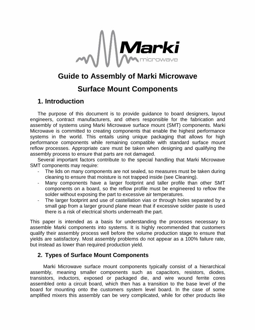
- Castellation Via A castellation via is a method of creating a transition by making a plated through hole in a circuit and cutting the through hole in half. Two ground holes can be placed on either side to create a quasi-coplanar waveguide transmission line. The transmission will appear more inductive than in an EZ eyelet, since ground is only supplied on two sides. Further, it is limited to certain materials that are capable of supporting the construction. It is however very robust and is a visible transition, making it easier to inspect the solder fillets. Product Lines: T3 Mixers, Baluns, High Isolation Power Combiners (PBR), T3A3 Carrier Material: FR4 or Rogers 4003 Max Recommended Frequency: 20 GHz Suspended Substrate Compatible: No Lead-Free Option: Yes (CQG/CTG/CKG)
- Plated Through Hole
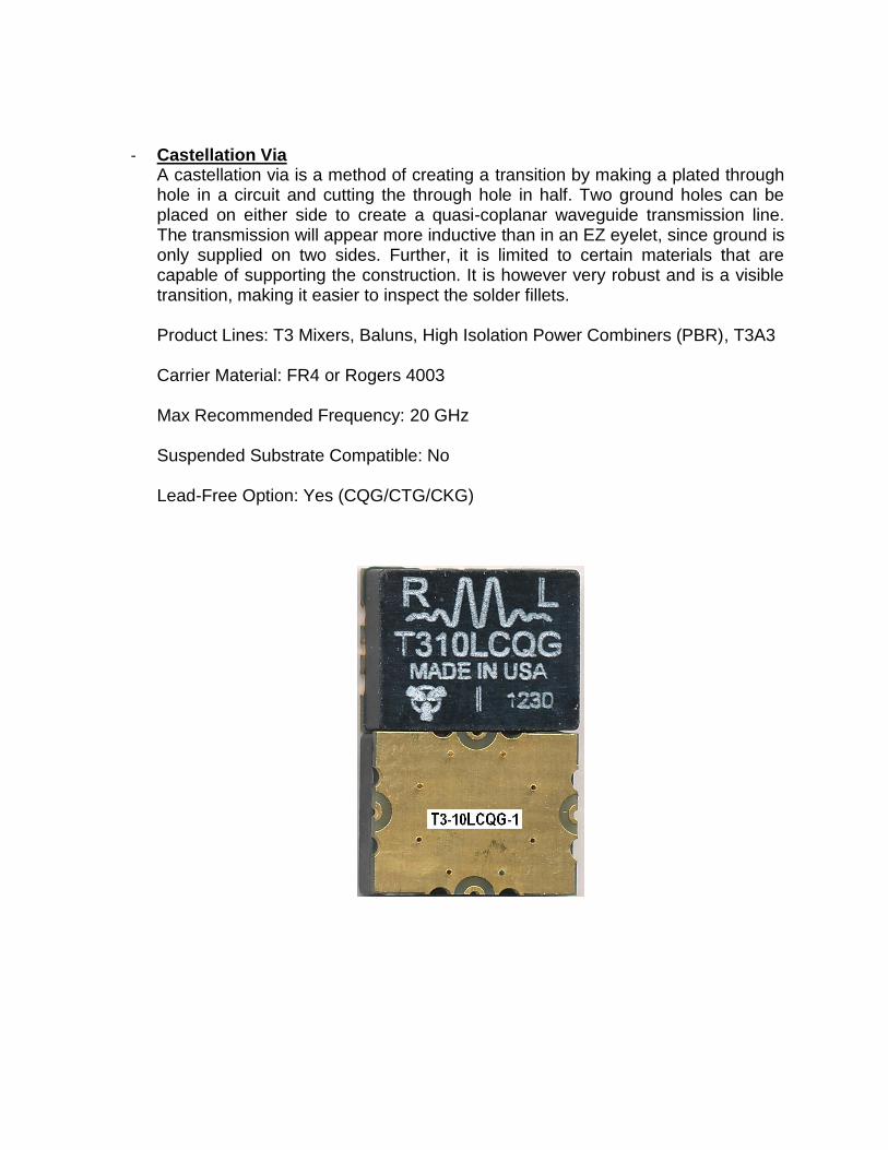
This is a standard way to achieve surface mount transitions. It is just a drilled hole that is metal plated, through the substrate, to the signal trace on the bottom side. The separation from ground is engineered on the top and bottom to minimize inductive losses. It can be created with a wider variety of materials, including thinner and lower dielectric materials. Because it is used with thinner materials, it is typically only associated with smaller parts, to keep the board flat and prevent it from warping during assembly. Because it is used with thinner materials the transition can appear less inductive, thus performing to higher frequencies. Product Lines: Bias Tees, some Power Dividers, Diplexers Carrier Material: PTFE Max Recommended Frequency: 35 GHz Suspended Substrate Compatible: No Lead-Free Option: Yes (SMG)

- Filled Via This is similar to the plated through hole, but it is created on a ceramic substrate by completely filling the hole with metal instead of just plating the sidewalls. The increased metal thickness decreases the inductance of the transition and can provide for (gross leak) sealed packages if required. It is only available for ceramic components. The increased thickness of these components compared to the substrates used for plated through hole transitions means that the frequency coverage is comparable to our plated through hole components. Product Lines: All Microlithics (Mixers, Doublers, IQ Mixers, Baluns), some Power Dividers Carrier Material: Alumina Max Recommended Frequency: 32 GHz (at present, higher may be possible) Suspended Substrate Compatible: No Lead-Free Option: Intrinsically Lead-Free
3. Layout Design
Surface mount footprints are available for most products, reachable in several ways. They are generally linked from the datasheet, available under the ‘Tech Docs’ tab on the product page, and listed at: http://www.markimicrowave.com/1939/Carrier_PCB_Tech_Notes.aspx
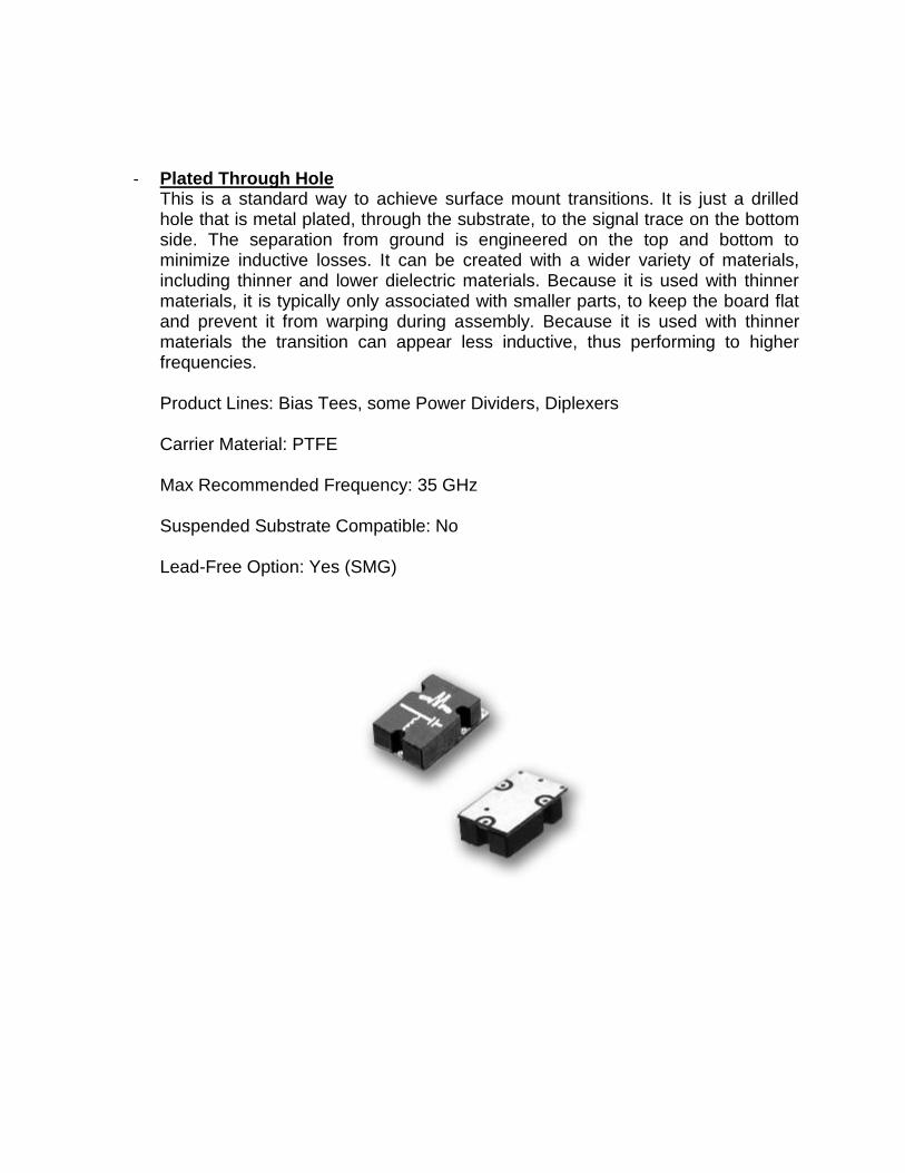
The typical footprint shows the outline of the component case, signal traces, ground holes, and clearance on a ground pad. All Marki surface mount components consist of ground planes combined with signal traces, so a large ground pad is generally required beneath the board. At low frequencies (<6 GHz) the placement and number of plated through holes is not as critical, although solid grounding is still required. Generally we will show many plated through holes, particularly near the transitions, to guarantee 50 ohm traces. These plated through holes may be moved or changed to accommodate layout issues. At higher frequencies (>10 GHz) the grounding of the component becomes critical, and plated through holes should be followed closely.
The traces shown represent placement on an arbitrary substrate. Since our products are used with a variety of substrate materials and thicknesses, it is left to the customer to engineer the transition into the signal pad. In general a gradual taper from the signal ports to the 50 ohm traces on the board is desired.
.
Fig. 1: Typical supplied footprint, for BTSML package

4. Use of Pick and Place Assembly
Marki components are generally suitable for pick and place assembly. The use of plastic lids allows most parts to be picked up and moved by vacuum tip manipulators. Marki products are not generally available on tape and reel packaging, although most products can be packaged into reels for an additional fee at the customer’s request. When using pick and place assembly methods, the guidelines below for reflow temperature and cleaning must be followed.
5. Hand Mounting Assembly Method
EZ amplifiers and T3A mixers with integrated LO amplifiers must always be hand assembled, due to the use of exposed amplifier die. Other Marki surface mount parts can always be hand assembled, and it is recommended to attempt hand assembly when manufacturing yield issues arise, especially for very tall or large footprint packages.
Marki Hand Mounting Assembly Process
1) Prior to installation of the Marki components, populate all reflow-compatible surface mount components onto the PCB. When solder reflow and/or aqueous cleaning procedures are used, ensure these steps are completed prior to hand installation of EZ amplifiers and T3A mixers since they are not compatible with hand assembly.
2) Apply silver epoxy paste to the ground pad. Avoid the application of large amounts of epoxy in order to prevent shorts between the ground and signal lines. Apply epoxy in small “dots”.
3) While holding the unit in place using tweezers or mounting screws, hand solder all signal I/O and bias pins. Do not apply the soldering iron to the I/O solder joint for longer than necessary to avoid damage to the component. A lower melting temperature eutectic solder such as Sn63/Pb37 is preferred, although lead-free solders can also be used.
4) Cure the silver epoxy according to the epoxy manufacturer’s instructions.
5) If required, clean the assembly by wiping with isopropyl alcohol by hand.
6) (OPTIONAL) DC probe the I/O lines and verify the connections. Consult the Marki
datasheets for DC circuit connections. If DC probe data is not available, contact the factory for proper readings.
Further, metal or nylon screws can generally be used to temporarily or permanently secure the parts to a solid metal or plated circuit ground plane. Use of these screws is always optional for surface mount components (though it may be required for carrier assemblies).

6. Solder Selection and Reflow After the cleaning process, reflow temperatures are the second most common
cause of failures amongst assembled Marki parts. Marki uses either high temperature leaded solder (for leaded parts) or gold-tin eutectic solder for lead-free parts. The maximum temperature and time these parts will survive is specified by the reflow profile (for leaded or lead free) detailed in IPC/JEDEC J-STD-020D.1.
225°C
25°C
Tem
pera
ture
183°C
Time 25°C to Peak
6 Minutes Maximum
tP
Tsmax
T smin
Preheat Area
Max. Ramp Up Rate = 3°C/s
Max. Ramp Down Rate = 6°C/s
220°C
20 seconds
t
p
L
t s
60-150 seconds
60-120 seconds
T - Peak
Temperature
LT - Liquidous
Temperature
150°C
100°C
Time
SN63 Eutectic Process Temperature Profilefor Marki Microwave Surface Mount Devices
Reference: IPC/JEDEC J-STD-020D.1
Fig. 2: Leaded Reflow Profile

260°C
25°C
Tem
pera
ture
217°C
Time 25°C to Peak
8 Minutes Maximum
tP
Tsmax
T smin
Preheat Area
Max. Ramp Up Rate = 3°C/s
Max. Ramp Down Rate = 6°C/s
255°C
30 seconds
t
p
L
t s
60-150 seconds
60-120 seconds
T - Peak
Temperature
LT - Liquidous
Temperature
200°C
150°C
Time
PB-Free Process Temperature Profilefor Marki Microwave Surface Mount Devices
Reference: IPC/JEDEC J-STD-020D.1
Fig. 3: Lead-free Reflow Profile Whenever possible, we strongly recommend the use of no-clean solder with the
lowest melting temperature and time above liquidous possible. This will prevent heat damage to Marki components that can occur during the reflow process.
The reason that high profile parts can be damaged during the reflow process is that the temperature sensors that control the oven temperature are usually located on the circuit board surface, but the heating in the peak temperature range frequently occurs by use of high temperature forced air method that allows shorter time above liquidous. This causes the top of the part to heat significantly more than the bottom surface, on the bottom PWB. The components inside can experience significantly higher temperatures than other lower profile components.
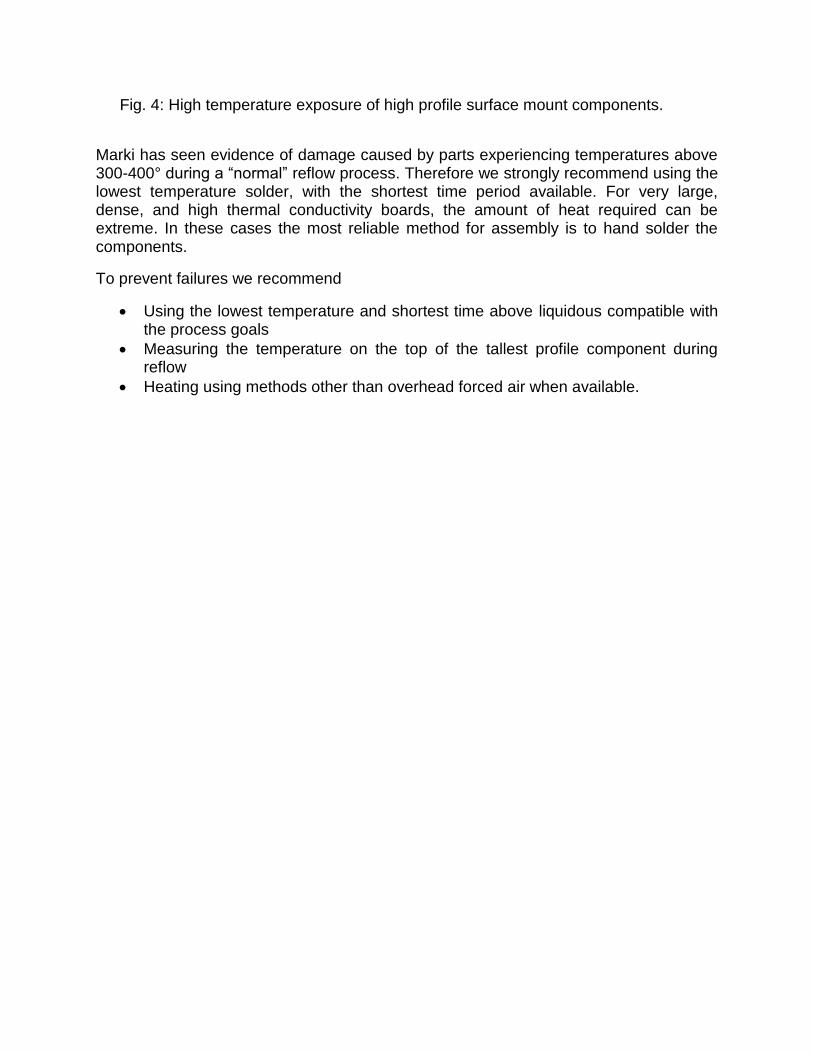
Fig. 4: High temperature exposure of high profile surface mount components.
Marki has seen evidence of damage caused by parts experiencing temperatures above 300-400° during a “normal” reflow process. Therefore we strongly recommend using the lowest temperature solder, with the shortest time period available. For very large, dense, and high thermal conductivity boards, the amount of heat required can be extreme. In these cases the most reliable method for assembly is to hand solder the components.
To prevent failures we recommend
Using the lowest temperature and shortest time above liquidous compatible with the process goals
Measuring the temperature on the top of the tallest profile component during reflow
Heating using methods other than overhead forced air when available.

7. Cleaning
The wide variety of cleaning processes, solutions, drying techniques, and cleaning equipment make this step the most varied and prone to error. Many legacy surface mount products are NOT moisture sealed, and the lid is only a mechanical cover that is epoxied in place. With the exception of amplifiers, Marki components are classified as moisture sensitivity level 1, meaning that they can be mounted and reflowed an unlimited amount of time after they are removed from the packaging. Further, they are not generally sensitive to cleaning liquids.
However, the use of unsealed lids means that moisture can become trapped under the cover of the part, causing electrical shorts and other failure modes. This is particularly true when the part is cleaned with room temperature solutions when the board is still hot. The rapid cooling inside the component will cause a pressure differential that will draw moisture inside of the cover. This problem can be mitigated by allowing the board to cool before cleaning.
In general these failure modes are temporary for passive products and mixers. Once the moisture is removed the part will return to normal operating specifications. In order to accommodate this, Marki recommends the following:
All surface mount components subject to aqueous cleaning should be subjected to a vacuum bake at 120° to 140 C° for one hour.
In general this will remove all moisture from the package. If a vacuum oven is not available, or if it is desired to bake at a lower temperature, then a longer bake time at a lower temperature at atmospheric pressure is acceptable. Experimentation during process qualification may be required to find the optimal bake time.

8. In Case of Failures
If intermittent system level failures occur and are traced to low yield of Marki components on the board, the following procedures should be taken:
1) Subject the board to an extended bake out. If this causes some units to pass, then it is most likely a moisture problem and the cleaning/bake out procedure needs to be re-evaluated.
2) Do NOT remove components from the board with a hot air gun. The heat applied by a hot air gun will damage the components due to excessive temperature.
3) If the board can be safely heated with a hot plate, then components may be removed in this manner. Remove the questionable component, clean the area, and re-attach it by hand. This will indicate if a short between the ground plane and the signal trace was present.
4) If the part cannot be safely heated on a hot plate, contact [email protected] for further assistance. Marki staff can assist with certain ‘in situ’ diagnostic tests that will help determine possible failure mechanisms.