guide to running kasp genotyping reactions on the thermo ...€¦ · for any queries on this manual...
TRANSCRIPT

extraction • sequencing • genotyping • extraction • sequencing • genotypin
g • e
xtraction • sequencing • genotyping • extraction • sequencing • genotyping •
Guide to running KASP genotyping reactions on the Thermo Scientific PikoReal instrument

Contents of this guide for the Thermo ScientificTM PikoRealTM instrument
1 Introduction
2 Tips and suggestions before you start
3 Overview of the procedure
4 KASP thermal cycling conditions
5 Step by step user guide
5.1 Create a new experiment for KASP genotyping
5.2 Select the fluorophores for KASP genotyping
5.3 Program the KASP thermal cycle
5.3.1 Program a baseline read
5.3.2 Program the activation stage
5.3.3 Program the touchdown stage
5.3.4 Program the amplification stage
5.3.5 Program the plate read stage
5.3.6 The thermal cycling protocol
5.4 Program the plate layout for the experiment and start the run
5.5 Analysis of results
5.5.1 Performing data analysis
5.5.2 Defining virtual standards
5.6 Recycle your reaction plate if required
5.7 Running the KASP trial kit on the PikoReal instrument
Photograph used courtesy of Thermo Fisher Scientific; copying prohibited.

1For any queries on this manual or running KASP reactions in your laboratory please contact:All locations except USA: Email: [email protected] • Phone: +44 (0)1992 476 486USA only: Email: [email protected] • Phone: +1 978 338 5317
1. Introduction
This document is intended as a guide to running KASP™ genotyping reactions on the Thermo
Scientific PikoReal instrument.
KASP chemistry for allelic discrimination performs well on a Thermo Scientific PikoReal
instrument and this step-by-step protocol will enable users to successfully set-up, run and read
plates on the Thermo Scientific PikoReal.
2. Tips and suggestions before you start
1. Optimal cycling conditions for KASP require a touchdown 2-step PCR protocol. The cycling
conditions for most assays will be as described in this manual (Section 4), although you must check
the cycling conditions included in your assay information pack to ensure that your assay does not
have any specific cycling conditions.
2. KASP is an endpoint chemistry and will require a final read once the PCR amplification steps have
been completed. Completed KASP reactions must be read below 40ºC.
3. Data capture should only be performed at the end of the thermal cycle program – no useful data will
be captured during the thermal cycling protocol.
4. The KASP recycling program will often improve results, especially for assays that are slow to form
clusters.
3. Overview of the procedure
1. Create a new experiment for KASP genotyping – see Section 5.1.
2. Select the fluorophores for KASP genotyping – see Section 5.2.
3. Program the thermal cycling conditions – see Section 5.3.
4. Program the plate set-up including sample type – see Section 5.4.
5. View the data – see Section 5.5.
6. Recycle the plate if necessary – see Section 5.6.

2For any queries on this manual or running KASP reactions in your laboratory please contact:All locations except USA: Email: [email protected] • Phone: +44 (0)1992 476 486USA only: Email: [email protected] • Phone: +1 978 338 5317
4. KASP thermal cycling conditions
4.1 KASP thermal cycling conditions
Stage 1
• 94ºC 15 minutes
Stage 2
• 94ºC 20 seconds
• 61ºC 60 seconds1
1Drop -0.6ºC per cycle
Repeat Stage 2 x9 times (a total of 10 cycles) achieving a final annealing temperature of
55.6ºC.
Stage 3
• 94ºC 20 seconds
• 55ºC 60 seconds
Repeat Stage 3 x25 times (a total of 26 cycles)
Stage 4
• Add read step at 37ºC for 1 min*
4.2 KASP recycling conditions
Stage 1
• 94ºC 20 seconds
• 57ºC 60 seconds
Repeat steps 1-2 twice (a total of 3 cycles)
Stage 2
• Add read step at 37ºC for 1 min*
*KASP cannot be read at temperatures above 40ºC.
Please note: We can provide a setup file for this machine for standard KASP thermal cycling. Please
contact the technical support team (details at the end of this document) for further information.

3For any queries on this manual or running KASP reactions in your laboratory please contact:All locations except USA: Email: [email protected] • Phone: +44 (0)1992 476 486USA only: Email: [email protected] • Phone: +1 978 338 5317
5. Step by step user guide
5.1 Create a new experiment for KASP genotyping
• Open the PikoReal software by double-clicking
on the desktop icon.
• Click on the ‘New’ button in the ‘Experiment’
menu bar.
• A new experiment will be created in the ‘Active
Experiments’ section of the window.
5.2 Select the fluorophores for KASP genotyping
• Click on the ‘Protocol’ tab to enable selection of
the required fluorophores and programming of
the KASP thermal cycling conditions.
• The initial view will contain all available
fluorophores and default thermal cycling
conditions.
Default ‘Protocol’ tab view within the PikoReal software
4For any queries on this manual or running KASP reactions in your laboratory please contact:All locations except USA: Email: [email protected] • Phone: +44 (0)1992 476 486USA only: Email: [email protected] • Phone: +1 978 338 5317
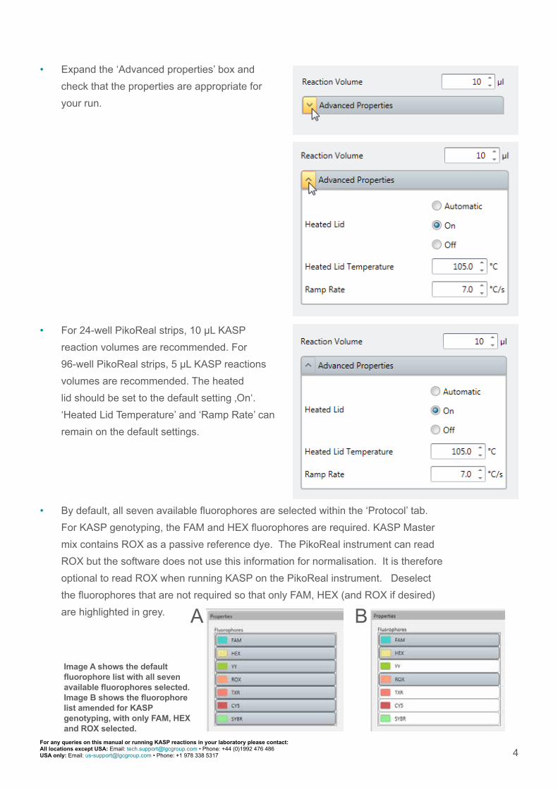
• By default, all seven available fluorophores are selected within the ‘Protocol’ tab.
For KASP genotyping, the FAM and HEX fluorophores are required. KASP Master
mix contains ROX as a passive reference dye. The PikoReal instrument can read
ROX but the software does not use this information for normalisation. It is therefore
optional to read ROX when running KASP on the PikoReal instrument. Deselect
the fluorophores that are not required so that only FAM, HEX (and ROX if desired)
are highlighted in grey.
• Expand the ‘Advanced properties’ box and
check that the properties are appropriate for
your run.
• For 24-well PikoReal strips, 10 µL KASP
reaction volumes are recommended. For
96-well PikoReal strips, 5 µL KASP reactions
volumes are recommended. The heated
lid should be set to the default setting ‚On‘.
‘Heated Lid Temperature’ and ‘Ramp Rate’ can
remain on the default settings.
Image A shows the default fluorophore list with all seven available fluorophores selected. Image B shows the fluorophore list amended for KASP genotyping, with only FAM, HEX and ROX selected.
A B

5For any queries on this manual or running KASP reactions in your laboratory please contact:All locations except USA: Email: [email protected] • Phone: +44 (0)1992 476 486USA only: Email: [email protected] • Phone: +1 978 338 5317
5.3 Program the KASP thermal cycle on the PikoReal
• Within the ‘Protocol’ tab, edit the thermal
cycle to the conditions required for KASP
genotyping. The stages of the KASP
thermal cycling program are detailed in
Section 4.1.
• The default cycling conditions in the
PikoReal software will be as shown in the
protocol tree opposite.
5.3.1 Program a baseline read at 37ºC for 1
minute. Right click on ‘Protocol’ at the top of
the protocol tree, and ‘Add temperature step’.
Edit the parameters on the right hand side of
the window.
6For any queries on this manual or running KASP reactions in your laboratory please contact:All locations except USA: Email: [email protected] • Phone: +44 (0)1992 476 486USA only: Email: [email protected] • Phone: +1 978 338 5317
• Add a data acquisition step to this temperature
step by right clicking on the temperature branch
in the protocol tree, and selecting ‘Add data
acquisition step’.
• The protocol tree will then appear as below (the
added step is outlined in green)
• The properties of the ‘Data Acquisition’ step
should correspond to the fluorophores that you
selected in Section 5.2, and will ensure that
the correct fluorophores are read to generate
KASP genotyping results.

7For any queries on this manual or running KASP reactions in your laboratory please contact:All locations except USA: Email: [email protected] • Phone: +44 (0)1992 476 486USA only: Email: [email protected] • Phone: +1 978 338 5317
5.3.2. Program the activation stage (Stage 1):
• 94ºC 15 minutes.
Click on the second temperature branch in the
protocol tree, and edit the parameters on the right
hand side of the window.
• The protocol tree will then appear as below (the
edited branch is outlined in green).

8For any queries on this manual or running KASP reactions in your laboratory please contact:All locations except USA: Email: [email protected] • Phone: +44 (0)1992 476 486USA only: Email: [email protected] • Phone: +1 978 338 5317
5.3.3. Program the touchdown stage (Stage 2) (10 cycles):
• 94ºC 20 seconds
• 61ºC 60 seconds (drop -0.6ºC /per cycle)
Click on the ‘Cycle’ branch in the protocol tree, and
edit the parameters on the right hand side
of the window.
Please note: to program the temperature
touchdown stage, you will need to do the following:
• Set the total number of cycles for this step to
10. N.B. A drop of -0.6ºC per cycle will achieve
a final annealing temperature of 55.6ºC.
• Ensure that the temperatures and times are
programmed correctly for each of the two steps
of the amplification stage – these can be edited
in the ‘Properties’ box.
• To set the temperature decrement: Click
on the ‘Temperature 61ºC, 01:00’ step and
expand the ‘Advanced Properties’ box. Set the
‘Temperature Change Per Cycle’ to 0.6ºC, and
tick the ‘Temperature Decrement’ box to ensure
that the temperature decreases each cycle
rather than increases.
9For any queries on this manual or running KASP reactions in your laboratory please contact:All locations except USA: Email: [email protected] • Phone: +44 (0)1992 476 486USA only: Email: [email protected] • Phone: +1 978 338 5317
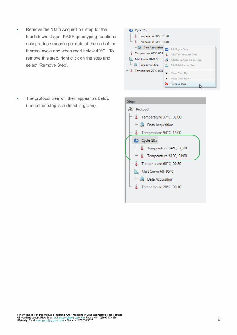
• Remove the ‘Data Acquisition’ step for the
touchdown stage. KASP genotyping reactions
only produce meaningful data at the end of the
thermal cycle and when read below 40ºC. To
remove this step, right click on the step and
select ‘Remove Step’.
• The protocol tree will then appear as below
(the edited step is outlined in green).

10For any queries on this manual or running KASP reactions in your laboratory please contact:All locations except USA: Email: [email protected] • Phone: +44 (0)1992 476 486USA only: Email: [email protected] • Phone: +1 978 338 5317
5.3.4 Program the amplification stage (Stage 3) (26 cycles):
• 94ºC 20 seconds
• 55ºC 60 seconds
Please note: to program the amplification stage, you will need to do the following:
• Add an additional ‘Cycle’ branch to the default
thermal cycle that is pre-programmed within the
software. Click on the ‘Cycle’ symbol at the top
of the window and an additional ‘Cycle’ stage
will be added to the thermal cycle (if the ‘Cycle’
button is greyed out, click on the protocol tree
to enable this button to be used). Ensure that
this additional ‘Cycle’ stage is added at the
same ‘level’ as the touchdown cycle stage.
• NB. If the new cycle stage is added too far up
or down in the tree, right click on the stage and
select ‘Move Step Up’ or ‘Move Step Down’ as
appropriate.
• Add temperature steps to this ‘Cycle’ stage by
clicking on the ‘Temperature’ symbol at the top
of the window. Do this twice to add two steps
as required for KASP thermal cycling.

11For any queries on this manual or running KASP reactions in your laboratory please contact:All locations except USA: Email: [email protected] • Phone: +44 (0)1992 476 486USA only: Email: [email protected] • Phone: +1 978 338 5317
• Set the number of cycles for the amplification
stage to 26 (the default is 40).
• Ensure that the temperatures and times are
programmed correctly for each of the two steps
of the amplification stage – these can be edited
in the ‘Properties’ box.
• Remove the default ‘Temperature 60ºC, 00:30’
and ‘Melt Curve 60-95ºC’ steps from the end
of the thermal cycle as these are not required.
To remove these steps, right click on each step
and select ‘Remove Step’.
• After programming the amplification stage
(Stage 3) the protocol tree will then appear as
below (the edited step is outlined in green).
12For any queries on this manual or running KASP reactions in your laboratory please contact:All locations except USA: Email: [email protected] • Phone: +44 (0)1992 476 486USA only: Email: [email protected] • Phone: +1 978 338 5317
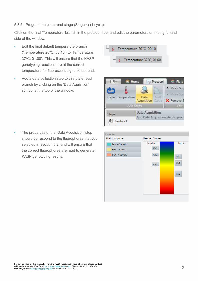
5.3.5 Program the plate read stage (Stage 4) (1 cycle):
Click on the final ‘Temperature’ branch in the protocol tree, and edit the parameters on the right hand
side of the window.
• Edit the final default temperature branch
(‘Temperature 20ºC, 00:10’) to ‘Temperature
37ºC, 01:00’. This will ensure that the KASP
genotyping reactions are at the correct
temperature for fluorescent signal to be read.
• Add a data collection step to this plate read
branch by clicking on the ‘Data Aquisition’
symbol at the top of the window.
• The properties of the ‘Data Acquisition’ step
should correspond to the fluorophores that you
selected in Section 5.2, and will ensure that
the correct fluorophores are read to generate
KASP genotyping results.

13For any queries on this manual or running KASP reactions in your laboratory please contact:All locations except USA: Email: [email protected] • Phone: +44 (0)1992 476 486USA only: Email: [email protected] • Phone: +1 978 338 5317
• After programming the plate read stage (Stage
4) the protocol tree will then appear as below
(the edited step is outlined in green).
5.3.6 The thermal cycling protocol
Once the thermal cycling protocol for KASP has
been correctly programmed, it can be viewed in the
left hand tree and in graphical format at the bottom
of the window. The graphical format displays
the approximate run time for the thermal cycling
protocol - this should be around 01:22:00 (run time
outlined in green in graphical format below).

14For any queries on this manual or running KASP reactions in your laboratory please contact:All locations except USA: Email: [email protected] • Phone: +44 (0)1992 476 486USA only: Email: [email protected] • Phone: +1 978 338 5317
5.4 Program the plate layout for the experiment and start the run
Once the KASP thermal cycling protocol has been programmed correctly, click on the
‘Plate Layout’ tab to define the plate parameters. Please note that the plate layout can
also be edited during or after the run.
• Click on the ‘Pipette’ symbol at the top of the
window to enter the pipetting mode
• Define the appropriate pipette content for
the KASP genotyping reaction plate. Click
on the FAM fluorophore to move it from the
‘Fluorophore’ list into the ‘Pipette Content’
list. The fluorophore will move to the ‘Pipette
Content’ list and the box will be filled in with the
appropriate colour.
• Once a fluorophore is in the ‘Pipette Content’
list, the ‘Sample Type’ options will become
available. Click on ‘Unknown’ from this list, and
it will be added to the FAM fluorophore in the
‘Pipette Content’ list (shown by the purple circle
containing the letter U).
• Repeat this process for HEX and ROX (if you
have chosen to read this) fluorophores. The
‘Pipette Content’ list should then contain all
three fluorophores, each with the ‘Unknown’
sample type assigned to them.
• ‘Pipette’ the content into the wells on the plate
layout by clicking on the relevant wells (i.e.
those that will contain DNA samples).

15For any queries on this manual or running KASP reactions in your laboratory please contact:All locations except USA: Email: [email protected] • Phone: +44 (0)1992 476 486USA only: Email: [email protected] • Phone: +1 978 338 5317
• In the ‘Pipette Content’ list, highlight the
FAM fluorophore by clicking on it. Click on
‘NTC’ within the ‘Sample Type’ list and the
fluorophore will now display a grey circle with
the letter O. Repeat this for the HEX and ROX
fluorophores.
• ‘Pipette’ the content into the wells on the plate
layout by clicking on the relevant wells (i.e.
those that contain the no template controls).
• In the PikoReal plate layout, it is important to
add an AD standard for each of the expected
genotypes. An AD standard is a well containing
DNA of a known genotype, and the software
uses this information to automatically call the
genotypes of the unknown samples. Without
AD standards, genotyping clusters will still be
apparent on the cluster plot, but the software
will not automatically assign genotypes and
colour-code the datapoints. It is possible to
manually assign genotypes based on clusters,
in the absence of controls, using the ‘Virtual
Standards’ function within the analysis tab (See
Section 5.5.2 for more details).
• Click on a well containing a sample of known
genotype e.g. homozygous FAM (X:X), and
switch to the ‘Select’ mode (rather than‘Pipette’
mode).

16For any queries on this manual or running KASP reactions in your laboratory please contact:All locations except USA: Email: [email protected] • Phone: +44 (0)1992 476 486USA only: Email: [email protected] • Phone: +1 978 338 5317
• For the highlighted well, change the sample
type for the relevant fluorophore(s) to ‘AD /
HRM standard’. Genotype information must
also be added to the ‘Call’ box for the relevant
fluorophore(s), otherwise the software will not
automatically call the genotypes
• For a homozygous FAM (X:X) positive
control, first click on the FAM fluorophore
in the ‘Fluorophores’ box
• Change the sample type to ‘AD / HRM
standard’ using the drop down menu in the
‘Properties’ box
• In the ‘Call’ box, define the genotype for
the FAM allele e.g. ‘C’

17For any queries on this manual or running KASP reactions in your laboratory please contact:All locations except USA: Email: [email protected] • Phone: +44 (0)1992 476 486USA only: Email: [email protected] • Phone: +1 978 338 5317
• Click on the HEX fluorophore in the
‘Fluorophores’ box
• As this is the homozygous FAM (X:X)
positive control, change the sample type
for the HEX fluorophore to ‘Empty’. No call
information is therefore required for this
fluorophore.
• The table below details how to program
AD standard wells for each of the possible
genotypes
Genotype (Call) FAM sample type and call HEX sample type Well in plate layout
Homozygous FAM (X:X)
AD / HRM Standard Call: X (or equivalent base e.g. A, T, C, G)
Empty Call: n/a
Heterozygous (X:Y)
AD / HRM Standard Call: X (or equivalent base e.g. A, T, C, G)
AD / HRM Standard Call: Y (or equivalent base e.g. A, T, C, G)
Homozygous HEX (Y:Y)
Empty Call: n/a
AD / HRM Standard Call: Y (or equivalent base e.g. A, T, C, G)
18For any queries on this manual or running KASP reactions in your laboratory please contact:All locations except USA: Email: [email protected] • Phone: +44 (0)1992 476 486USA only: Email: [email protected] • Phone: +1 978 338 5317
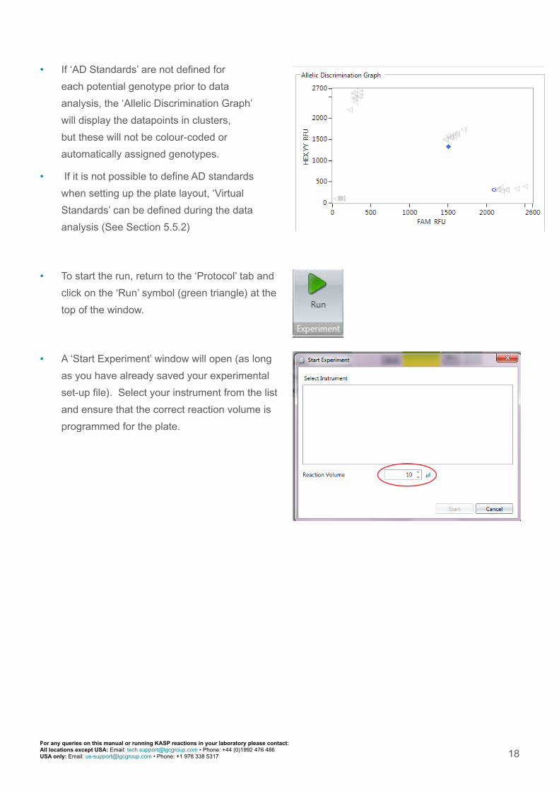
• If ‘AD Standards’ are not defined for
each potential genotype prior to data
analysis, the ‘Allelic Discrimination Graph’
will display the datapoints in clusters,
but these will not be colour-coded or
automatically assigned genotypes.
• If it is not possible to define AD standards
when setting up the plate layout, ‘Virtual
Standards’ can be defined during the data
analysis (See Section 5.5.2)
• To start the run, return to the ‘Protocol’ tab and
click on the ‘Run’ symbol (green triangle) at the
top of the window.
• A ‘Start Experiment’ window will open (as long
as you have already saved your experimental
set-up file). Select your instrument from the list
and ensure that the correct reaction volume is
programmed for the plate.

19For any queries on this manual or running KASP reactions in your laboratory please contact:All locations except USA: Email: [email protected] • Phone: +44 (0)1992 476 486USA only: Email: [email protected] • Phone: +1 978 338 5317
5.5 Analysis of results
5.5.1 Performing data analysis (with defined positive controls)
• Please note: if you have not been able to define positive controls (as detailed in Section 5.4), please
see Section 5.5.2 for information about defining virtual standards during the analysis process.
• Once the PCR program and plate read have
completed, an ‘Analysis’ tab will appear at
the top of the window, adjacent to the ‘Plate
Layout’ tab.
• As KASP is an endpoint chemistry, an ‘RFU
Based’ allelic discrimination analysis method
should be used.
• Within the ‘Analysis’ tab, either:
• Click on the ‘RFU Based’ button and select
the sample group (e.g. ‘All Wells’)
OR
• Right click on the ‘Analysis’ item in the left hand tree and select ‘Add’, then ‘Allelic
Discrimination (RFU) and then the sample group (e.g. ‘All wells’)
• Click on the newly created ‘Allelic
Discrimination’ item in the left hand tree to view
the data and settings.
• Use the plate layout at the bottom left of the
window to highlight the wells that you are
interested in i.e. highlight the wells that contain
your reactions. Selected wells will be outlined
with dark grey. If you do not select the required
wells, every well will be plotted on the allelic
discrimination plot, even if it does not contain
any fluorescent data.

20For any queries on this manual or running KASP reactions in your laboratory please contact:All locations except USA: Email: [email protected] • Phone: +44 (0)1992 476 486USA only: Email: [email protected] • Phone: +1 978 338 5317
• The default analysis settings for the allelic
discrimination plot will be shown on the right
hand side of the window and should be similar
to those in the screenshot below. NB. Click
on the ‘Advanced < <’ button to show the
‘Line Reference Point’ and ‘Distance Weight
Ratio’ options.
• Ensure that ‘DA1’ is selected for Baseline RFU,
and ‘DA2’ is selected for Endpoint RFU. This
will mean that the pre-PCR read data is used
for the baseline values, and that the post-PCR
read data is used for the endpoint analysis.
Default ‘Settings’ and ‘Advanced’ settings box
• To view the data correctly on the genotyping
results plate layout at the top right of the
window, you may need to adjust the ‘Distance
Weight Ratio’ within the ‘Advanced < <’ settings
options. We would suggest reducing this value
to 1.00 in the first instance as we found that
this meant that only the wells of interest were
included on the genotyping results plate layout.
Amended ‘Settings’ and ‘Advanced’ settings box, with ‘Distance Weight Ratio’ adjusted to 1.00

21For any queries on this manual or running KASP reactions in your laboratory please contact:All locations except USA: Email: [email protected] • Phone: +44 (0)1992 476 486USA only: Email: [email protected] • Phone: +1 978 338 5317
Image A shows the plate layout view with ‘Distance Weight Ratio’ set to the default of 5.00. Image B shows the plate layout with the ‘Distance Weight Ratio’ adjusted to 1.00. The adjustment means that only the wells containing completed KASP reactions are assigned a genotype and plotted on the cluster plot.
• An alternative option to adjusting the ‘Distance Weight Ratio’ is to use the ‘Sample Groups’ option
within the PikoReal software. This allows several wells on a plate to be combined into groups for
analysis, and will be particularly beneficial if running more than one assay per plate. It is beyond
the scope of this manual to explain this in detail, but a full explanation and instructions can be found
within the ‘Help’ section of the PikoReal software and in the Thermo Scientific PikoReal manual.
• The data will be plotted on a cluster plot in the top centre of the window. Each data point on the
plot represents one of the wells on the reaction plate. If the software is able to automatically call
the genotypes of the samples, the data points will be colour-coded. In the example below, the two
homozygote groups are green and orange, and the heterozygote samples are blue.
A B
• The data will also be detailed in a table at the bottom centre of the window. This will include the
fluorescent values for FAM and HEX, plus the genotyping call that has been assigned to each
sample.

22For any queries on this manual or running KASP reactions in your laboratory please contact:All locations except USA: Email: [email protected] • Phone: +44 (0)1992 476 486USA only: Email: [email protected] • Phone: +1 978 338 5317
5.5.2 Defining virtual standards
• To define virtual standards during data analysis, right click on a datapoint that is clearly located
within a cluster, and choose ‘Virtual Standard’, then ‘Add Virtual Standard’ from the options.
• A virtual standard datapoint will be added to the cluster plot.
23For any queries on this manual or running KASP reactions in your laboratory please contact:All locations except USA: Email: [email protected] • Phone: +44 (0)1992 476 486USA only: Email: [email protected] • Phone: +1 978 338 5317
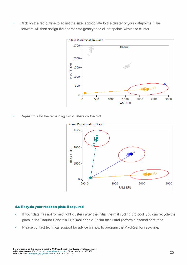
• Click on the red outline to adjust the size, appropriate to the cluster of your datapoints. The
software will then assign the appropriate genotype to all datapoints within the cluster.
• Repeat this for the remaining two clusters on the plot.
5.6 Recycle your reaction plate if required
• If your data has not formed tight clusters after the initial thermal cycling protocol, you can recycle the
plate in the Thermo Scientific PikoReal or on a Peltier block and perform a second post-read.
• Please contact technical support for advice on how to program the PikoReal for recycling.

www.lgcgroup.com
GermanyOstendstr. 25 • TGS Haus 812459 Berlin • Germany
Tel: +49 (0)30 5304 2200Fax: +49 (0)30 5304 2201Email: [email protected]
United Kingdom Unit 1-2 Trident Industrial Estate • Pindar Road
Hoddesdon • Herts • EN11 0WZ • UK
Tel: +44 (0)1992 470 757Fax: +44 (0)1438 900 670
Email: [email protected]
United States100 Cummings Center • Suite 420H
Beverly • MA 01915 • USA
Tel: +1 (978) 232 9430Fax: +1 (978) 232 9435
Email: [email protected]
For any queries about this guide or running KASP reactions in your laboratory
please contact the technical support team:
All locations except USA: email [email protected] or call +44 (0)1992 476 486
USA only: email [email protected] or call +1 978 338 5317
Instrument image is courtesy of Thermo Fisher Scientific, Inc. All other trademarks are the property of LGC and its subsidiaries. No part of this publication may be reproduced or transmitted in any form or by any means, electronic or mechanical, including photocopying, recording or any retrieval system, without the written permission of the copyright holder. © LGC Limited, 2014. All rights reserved. G5/CS/0215
5.7 Running the KASP trial kit on the Thermo Scientific PikoReal
• If you have requested a KASP trial kit to run on your Thermo Scientific PikoReal instrument, please
follow the protocol included with the kit to set up your reaction plate. This PikoReal manual can be
used to help you to program the instrument to run the trial kit reaction plate.
• After running the KASP thermal cycle on the PikoReal instrument, the trial kit reaction plate should
produce data similar to the figure below.
Results from the KASP trial kit reaction plate when run on the Thermo Scientific PikoReal instrument using the standard KASP thermal cycle