guided by - national institute of technology,...
TRANSCRIPT


GUIDED BY: SUBMITTED BY: DR. K.C . BISWAL. BIJAY KUMAR BEHERA DEPARTMENT OF CIVIL ROLL NO-10401033D. ENGG.NIT ROURKELA. FINAL YEAR CIVIL ENGG NIT ROURKELA .

DESIGN OF EARTH-QUAKE RESISTANT SIX-STORIED BUILDING LOCATED AT BHUJ A THESIS SUBMITTED IN PARTIAL FULFILLMENT OF THE REQUIREMENTS FOR THE DEGREE OF BACHELOR OF TECHNOLOGY IN CIVIL ENGINEERING BY
BIJAY KUMAR BEHERA Department of Civil Engineering National Institute of Technology Rourkela 2007

DESIGN OF EARTH-QUAKE RESISTANT SIX-STORIED BUILDING LOCATED AT BHUJ A THESIS SUBMITTED IN PARTIAL FULFILLMENT OF THE REQUIREMENTS FOR THE DEGREE OF BACHELOR OF TECHNOLOGY IN CIVIL ENGINEERING BY BIJAY KUMAR BEHERA
Under the Guidance of Dr. K.C.Biswal Department of Civil Engineering National Institute of Technology Rourkela 2007

National Institute of Technology Rourkela
CERTIFICATE This is to certify that the thesis entitled, Design of Earth-Quake Resistant Six-storied Building located at Bhuj submitted by Sri Bijay Kumar Behera in partial fulfillment of the requirements for the award of Bachelor of technology in Civil Engineering with specialization in Structural Engineering at the National Institute of Technology, Rourkela (Deemed Unversity) is an authentic work carried out by him under my supervision and guidance. To the best of my knowledge, the matter embodied in the thesis has not been submitted to any other Unversity/Institute for the award of any Degree or Diploma. Dr. K.C. Biswal Date: Department of Civil Engg. National Institute of Technology Rourkela-769008

ACKNOWLEDGEMENT
I would like to express my sincere gratitude to Dr. K.C .Biswal for his invaluable guidance. His continuous encouragement and support has always been an inspiration and a source of energy for me. He has not only guided in just technical matters but has always taught several important points to gain maturity to work and his nature of thinking has always influence me in many ways. I thank him for all of his efforts and help. I gratefully acknowledged Dr. K.C. Patra of Civil Engg. Department,NIT, Rourkela. for many good suggestions during the progress of project work.

CONTENTS 1. Introduction 1 1. Chapter-1 Problem statement 2 1.1.General 3-4 1.2.Plan of Building 5 1.3 Data 6 1.4.Geometry of Building 7-8 2. Chapter-2 Gravity load calculation 9 2.1.Member self weight 10 2.2.Beam and frame load 11-13 3. Chapter-3 Loading frame 14 3.1.Frame-A-A 16 3.2.Frame-B-B 17 3.3.Frame-1-1 18 3.4.Frame-2-2 19 3.5.Frame-3-3 20 3.6.Frame-4-4 21 3.7.Frame-C-C 22 3.8.Frame-D-D 23 4. Chapter-4 Seismic weight calculation 24 4.1.Seismic weight 25-27 4.2.Seismic load 27-29 4.3.Space frame 31 5. Chapter-5 Load combinations 32-34 6. Chapter-6
Storey drift and stability indices 35-38 7. Chapter-7 39 Design of beam 7.1.General requirements 40 7.2.Bending moment and shear forces 40-45 7.3.Flexure design 46-59 8. Chapter-8 Design of column 60 8.1.Effective length calculation 64 8.2.Transverse reinforcement 65-74

8.3.Reinforcement details 74-76
9. Chapter-9 Design of footing 77 9.1.Design 78-85 Conclusion 86-87 References 88

Abstract
linear structural changes.

INTRODUCTION Seismology is the study of earth vibrations mainly caused by earthquakes. The study of these vibrations by various techniques, understanding the nature and various physical processes that generate them from the major part of the seismology.
A seismic design of high rise buildings has assumed considerable importance in recent times. In traditional methods adopted based on fundamental mode of the structure and distribution of earthquake forces as static forces at various stories may be adequate for structures of small height subjected to earthquake of very low intensity but as the number of stories increases the seismic design demands more rigor.

CHAPTER-1
PROBLEM STATEMENT

Problem Statement:
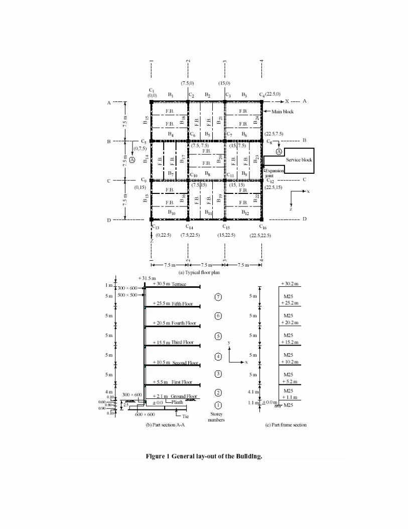
A six storey building for a commercial complex has plan dimensions as shown in Figure
1. The building is located in seismic zone V on a site with medium soil. Design the
building for seismic loads as per IS 1893
(Part 1): 2002.
General
1. The example building consists of the main block and a service block connected by
expansion joint and is therefore structurally separated (Figure 1). Analysis and design for
main block is to be performed.
2 The building will be used for exhibitions, as an art gallery or show room, etc., so that
there are
no walls inside the building. Only external walls 230 mm thick with 12 mm plaster on
both sides are considered. For simplicity in analysis, no balconies are used in the
building.
3. At ground floor, slabs are not provided and the floor will directly rest on ground.
Therefore, only ground beams passing through columns are provided as tie beams. The
floor beams are thus absent in the ground floor.
4. Secondary floor beams are so arranged that they act as simply supported beams and
that maximum number of main beams get flanged beam effect.
5. The main beams rest centrally on columns to avoid local eccentricity.
6. For all structural elements, M25 grade concrete will be used. However, higher M30
grade concrete is used for central columns up to plinth, in ground floor and in the first
floor.
7. Sizes of all columns in upper floors are kept the same; however, for columns up to
plinth, sizes
are increased.
8. The floor diaphragms are assumed to be rigid.
9. Centre-line dimensions are followed for analysis and design. In practice, it is advisable
to consider finite size joint width.
10. Preliminary sizes of structural components are assumed by experience.

11. For analysis purpose, the beams are assumed to be rectangular so as to distribute
slightly larger moment in columns. In practice a beam that fulfils requirement of flanged
section in design, behaves in between a rectangular and a flanged section for moment
distribution.
12. In Figure 1(b), tie is shown connecting the footings. This is optional in zones II and
III; however, it is mandatory in zones IV and V.
13. Seismic loads will be considered acting in the horizontal direction (along either of the
two principal directions) and not along the vertical direction, since it is not considered to
be significant.
14. All dimensions are in mm, unless specified otherwise.
Data of the Example
The design data shall be as follows:
Live load : 4.0 kN/m2 at typical floor
: 1.5 kN/m2 on terrace
Floor finish : 1.0 kN/m2
Water proofing : 2.0 kN/m2
Terrace finish : 1.0 kN/m2
Location : BHUJ city.
Wind load : As per IS: 875-Not designed for wind load, since
earthquake loads exceed the wind loads.
Earthquake load : As per IS-1893 (Part 1) - 2002
Depth of foundation below ground : 2.5 m
Type of soil : Type II, Medium as per IS:1893
Allowable bearing pressure : 200 kN/m2
Average thickness of footing : 0.9 m, assume isolated footings
Storey height : Typical floor: 5 m, GF: 3.4 m
Floors : G.F. + 5 upper floors.
Ground beams : To be provided at 100 mm below G.L.
Plinth level : 0.6 m
Walls : 230 mm thick brick masonry walls only at
periphery.
Material Properties
Concrete
All components unless specified in design: M25 grade all
Ec = 5 000 ck N/mm2 = 5 000 ck MN/m2 = 25 000 N/mm2 = 25 000 MN/m2 .
For central columns up to plinth, ground floor and first floor: M30
grade
Ec = 5 000 ck N/mm2 = 5 000 ck MN/m2 = 27 386 N/mm2 = 27 386 MN/m2 .
Steel
HYSD reinforcement of grade Fe 415 confirming to IS: 1786 is used throughout.

Geometry of the Building
The general layout of the building is shown in Figure 1. At ground level, the floor beams
FB are not provided, since the floor directly rests on ground (earth filling and 1:4:8 c.c. at
plinth level) and no slab is provided. The ground beams are provided at 100 mm below
ground level. The numbering of the members is explained as below.
Storey number
Storey numbers are given to the portion of the building between two successive grids of
beams. For the example building, the storey numbers are defined as follows:
Portion of the building Storey no.
Foundation top – Ground floor 1
Ground beams – First floor 2
First Floor – Second floor 3
Second floor – Third floor 4
Third floor – Fourth floor 5
Fourth floor – Fifth floor 6
Fifth floor - Terrace 7
Column number
In the general plan of Figure 1, the columns from C1 to C16 are numbered in a
convenient way from left to right and from upper to the lower part of the plan. Column
C5 is known as column C5 from top of the footing to the terrace level. However, to
differentiate the column lengths in different stories, the column lengths are known as 105,
205, 305, 405, 505, 605 and 705 [Refer to Figure 2(b)]. The first digit indicates the storey
number while the last two digits indicate column number. Thus, column length 605
means column length in sixth storey for column numbered C5. The columns may also be
specified by using grid lines.

Floor beams (Secondary beams)
All floor beams that are capable of free rotation at supports are designated as FB in
Figure 1. The reactions of the floor beams are calculated manually, which act as point
loads on the main beams. Thus, the floor beams are not considered as the part of the
space frame modelling.
Main beams number
Beams, which are passing through columns, are termed as main beams and these together
with the columns form the space frame. The general layout of Figure 1 numbers the main
beams as beam B1 to B12 in a convenient way from left to right and from upper to the
lower part of the plan. Giving 90o clockwise rotation to the plan similarly marks the
beams in the perpendicular direction. To floor-wise differentiate beams similar in plan
(say beam B5 connecting columns C6 and C7) in various floors, beams are numbered as
1005, 2005, 3005, and so on. The first digit indicates the storey top of the beam grid and
the last three digits indicate the beam number as shown in general layout of Figure 1.
Thus, beam 4007 is the beam located at the top of 4th storey whose number is B7 as per
the general layout.

CHAPTER-2
GRAVITY LOAD CALCULATION

Gravity Load calculations
Unit load calculations
Assumed sizes of beam and column sections are:
Columns: 500 x 500 at all typical floors
Area, A = 0.25 m2, I = 0.005208 m4
Columns: 600 x 600 below ground level
Area, A = 0.36 m2, I = 0.0108 m4
Main beams: 300 x 600 at all floors
Area, A = 0.18 m2, I = 0.0054 m4
Ground beams: 300 x 600
Area, A = 0.18 m2, I = 0.0054 m4
Secondary beams: 200 x 600
Member self- weights:
Columns (500 x 500)
0.50 x 0.50 x 25 = 6.3 kN/m
Columns (600 x 600)
0.60 x 0.60 x 25 = 9.0 kN/m
Ground beam (300 x 600)
0.30 x 0.60 x 25 = 4.5 kN/m
Secondary beams rib (200 x 500)
0.20 x 0.50 x 25 = 2.5 kN/m
Main beams (300 x 600)
0.30 x 0.60 x 25 = 4.5 kN/m
Slab (100 mm thick)
0.1 x 25 = 2.5 kN/m2
Brick wall (230 mm thick)
0.23 x 19 (wall) +2 x 0.012 x 20 (plaster) = 4.9 kN/m2
Floor wall (height 4.4 m)
4.4 x 4.9 = 21.6 kN/m
Ground floor wall (height 3.5 m)
3.5 x 4.9 = 17.2 kN/m

Ground floor wall (height 0.7 m)
0.7 x 4.9 = 3.5 kN/m
Terrace parapet (height 1.0 m)
1.0 x 4.9 = 4.9 kN/m
Slab load calculations
Component Terrace Typical
(DL + LL) (DL + LL)
Self (100 mm thick) 2.5 + 0.0 2.5 + 0.0
Water proofing 2.0 + 0.0 0.0 + 0.0
Floor finish 1.0 + 0.0 1.0 + 0.0
Live load 0.0 + 1.5 0.0 + 4.0
Total 5.5 + 1.5 kN/m2 3.5 + 4.0 kN/m2
Beam and frame load calculations:
(1) Terrace level:
Floor beams:
From slab
2.5 x (5.5 + 1.5) = 13.8 + 3.8 kN/m
Self weight = 2.5 + 0 kN/m
Total = 16.3 + 3.8 kN/m
Reaction on main beam
0.5 x 7.5 x (16.3 + 3.8) = 61.1 + 14.3 kN.
Note: Self-weights of main beams and columns will not be considered, as the analysis
software will directly add them. However, in calculation of design earthquake loads these
will be considered in the seismic weight.
Main beams B1–B2–B3 and B10–B11–B12
Component B1-B3 B2
From Slab
0.5 x 2.5 (5.5 +1.5) 6.9 + 1.9 0 + 0
Parapet 4.9 + 0 4.9 + 0
Total 11.8 + 1.9kN/m 4.9 + 0 kN/m
Two point loads on one-third span points for beams

B2 and B11 of (61.1 + 14.3) kN from the secondary beams.
Main beams B4–B5–B6, B7–B8–B9, B16–
B17– B18 and B19–B20–B21
From slab
0.5 x 2.5 x (5.5 + 1.5) = 6.9 + 1.9 kN/m
Total = 6.9 + 1.9 kN/m
Two point loads on one-third span points for all the main beams (61.1 + 14.3) kN from
the secondary beams.
Main beams B13–B14–B15 and B22–B23–B24
Component B13 – B15 B14
B22 – B24 B23
From Slab
0.5 x 2.5 (5.5 +1.5) ---- 6.9 + 1.9
Parapet 4.9 + 0 4.9 + 0
Total 4.9 + 0kN/m 11.8 + 1.9 kN/m
Two point loads on one-third span points for beams B13, B15, B22 and B24 of
(61.1+14.3) kN from the secondary beams.
(2) Floor Level:
Floor Beams:
From slab
2.5 x (3.5 + 4.0) = 8.75 + 10 kN/m
Self weight = 2.5 + 0 kN/m
Total = 11.25 + 10 kN/m
Reaction on main beam
0.5 x 7.5 x (11.25 + 10.0) = 42.2 + 37.5 kN.
Main beams B1–B2–B3 and B10–B11–B12
Component B1 – B3 B2
From Slab
0.5 x 2.5 (3.5 + 4.0) 4.4 + 5.0 0 + 0
Wall 21.6 + 0 21.6 + 0
Total 26.0 + 5.0 kN/m 21.6 + 0 kN/m

Two point loads on one-third span points for beams B2 and B11 (42.2 + 37.5) kN from
the
secondary beams.
Main beams B4–B5–B6, B7–B8–B9, B16– B17–B18 and B19–B20–B21
From slab 0.5 x 2.5 (3.5 + 4.0) = 4.4 + 5.0 kN/m
Total = 4.4 + 5.0 kN/m
Two point loads on one-third span points for all the main beams (42.2 + 37.5) kN from
the
secondary beams. Main beams
B13–B14–B15 and B22–B23–B24
Component B13 – B15 B14
B22 – B24 B23
From Slab
0.5 x 2.5 (3.5 + 4.0) ---- 4.4 + 5.0
Wall 21.6 + 0 21.6 + 0
Total 21.6 + 0 kN/m 26.0 + 5.0 kN/m
Two point loads on one-third span points for beams B13, B15, B22 and B24 of (42.2
+7.5) kN from the secondary beams.
(3) Ground level:
Outer beams: B1-B2-B3; B10-B11-B12; B13- B14-B15 and B22-B23-B24
Walls: 3.5 m high
17.2 + 0 kN/m
Inner beams: B4-B5-B6; B7-B8-B9; B16- B17-B18 and B19-B20-B21
Walls: 0.7 m high
3.5 + 0 kN/m

CHAPTER-3
LOADING FRAMES
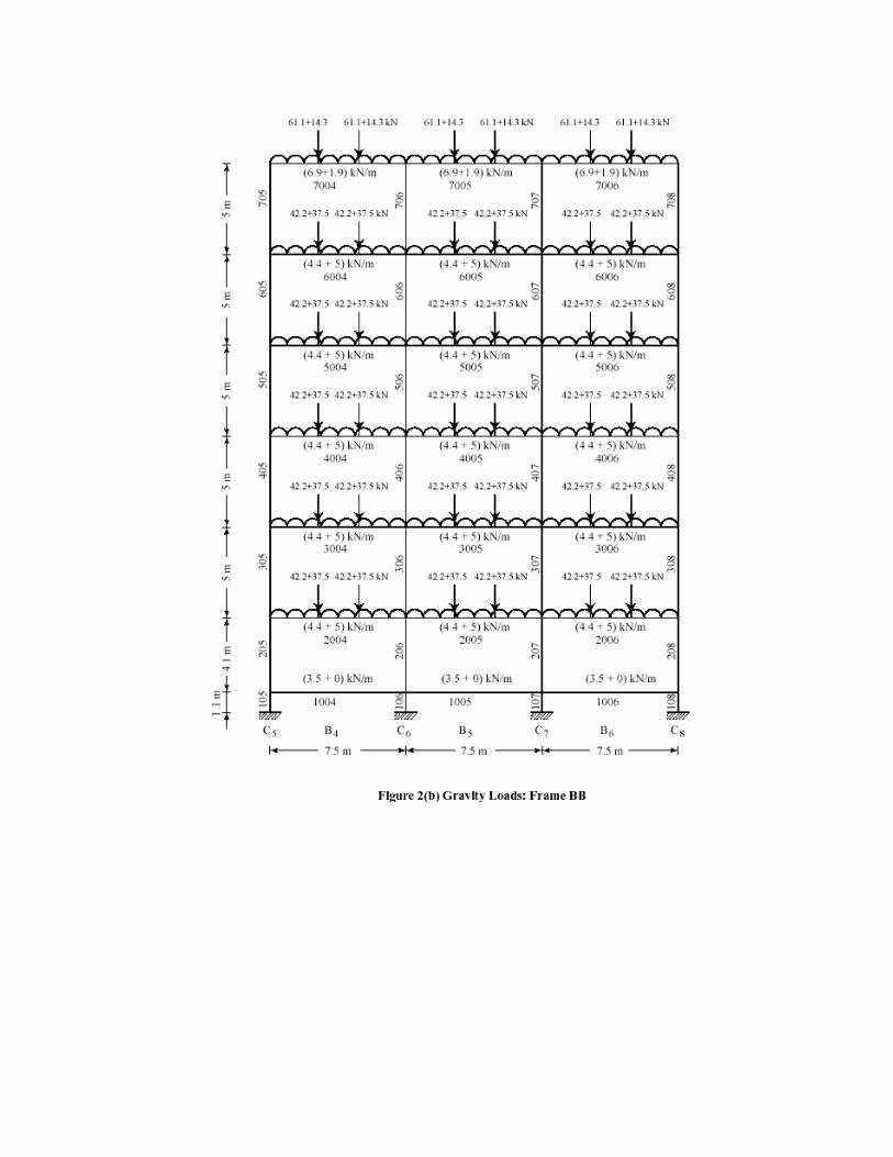
Loading frames
The loading frames using the above-calculated beam loads are shown in the figures 2 (a),
(b), (c)
and (d). There are total eight frames in the building. However, because of symmetry,
frames A-A, B-B, 1-1 and 2-2 only are shown. It may also be noted that since LL< (3/4)
DL in all beams, the loading pattern as specified by Clause 22.4.1 (a) of IS 456:2000 is
not necessary. Therefore design dead load plus design live load is considered on all spans
as per recommendations of Clause 22.4.1 (b). In design of columns, it will be noted that
DL + LL combination seldom governs in earthquake resistant design except where live
load is very high. IS: 875 allows reduction in live load for design of columns and
footings. This reduction has not been considered in this example.


FRAME-3-3

FRAME-4-4

FRAME-C-C
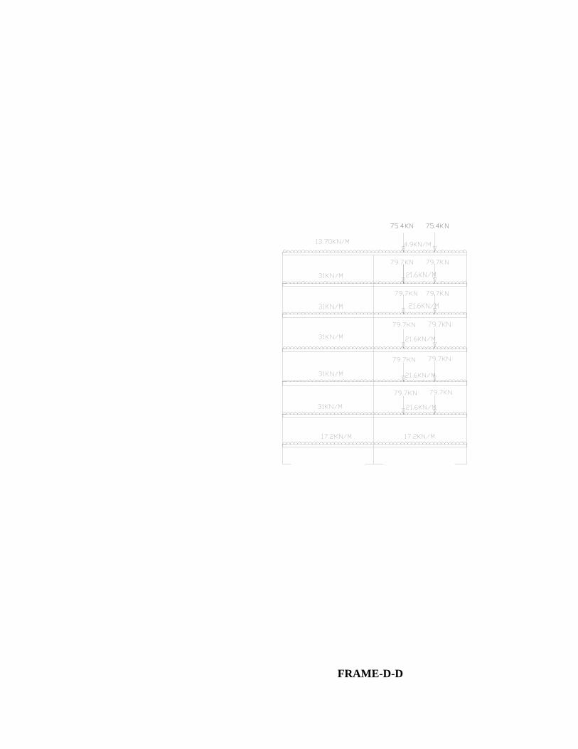
FRAME-D-D
CHAPTER-4
SEISMIC WEIGHT CALCULATION

Seismic Weight Calculations
The seismic weights are calculated in a manner similar to gravity loads. The weight of
columns and walls in any storey shall be equally distributed to the floors above and
below the storey. Following reduced live loads are used for analysis: Zero on terrace, and
50% on other floors [IS: 1893 (Part 1): 2002, Clause 7.4)
(1) Storey 7 (Terrace):
DL + LL
From slab 450x (5.5+0) 2 475 + 0
Parapet 4 x 22.5 (4.9 + 0) 441 + 0
Walls 0.5 x 4 x 22.5 x 972 + 0
(21.6 + 0)
Secondary beams 16 x 7.5 x (2.5 + 0) 300 + 0
Main beams 7.5 x 22 x (4.5 + 0) 743 + 0
Columns 0.5 x 5 x 15 x 236 + 0
(6.3 + 0)
Total 5 167 + 0
= 5 167 kN
(2) Storey 6, 5, 4, 3:
DL + LL
From slab 450 x 1 575+900
(3.5 + 0.5 x 4)
Walls 4 x 22. 5 x 1 944 + 0
(21.6 + 0)
Secondary beams 16 x 7.5 x 300+0
(2.5 + 0)
Main beams 7.5 x 22 x 743 + 0
(4.5 + 0)
Columns 15 x 5 x 473+0
(6.3 + 0)
Total 5035 +900
= 5935 kN
(3) Storey 2:
DL + LL
From slab 450x 1 575 +900
(3.5 + 0.5 x 4)
Walls 0.5 x 4 x 22.5 x 972 + 0
(21.6 + 0)
Walls 0.5 x 4 x 22.5 x 774 + 0
(17.2 + 0)
Secondary beams 16 x 7.5 x 300 + 0
(2.5 + 0)
Main beams 7.5 x 22 x 743 + 0
(4.5 + 0)
Columns 15 x 0.5 x 430 + 0
(5 + 4.1) x (6.3 + 0)
Total 5 794 +900
= 5694 kN
(4) Storey 1 (plinth):
DL + LL
Walls 0.5 x 4 x 22.5 774 + 0
(17.2 + 0)
Walls 0.5 x 4 x 22.5 x 158 + 0
(3.5 + 0)
Main beams 7.5 x 22 x 743 + 0
(4.5 + 0)
Column 15 x 0.5 x 4.1 x 194 + 0
(6.3 + 0)
15 x 0.5 x 1.1 x (9.0 + 0) 74 + 0
Total 1943 + 0
=1943 kN

Seismic weight of the entire building
= 5167 + 4 x 5935 + 5694 + 1943
= 36544 kN
The seismic weight of the floor is the lumped weight, which acts at the respective floor
level at the centre of mass of the floor.
Design Seismic Load
The infill walls in upper floors may contain large openings, although the solid walls are
considered in load calculations. Therefore, fundamental time period T is obtained by
using the following formula:
Ta = 0.075 h0.75
[IS 1893 (Part 1):2002, Clause 7.6.1]
= 0.075 x (30.5)0.75
= 0.97 sec.
Zone factor, Z = 0.36 for Zone V
IS: 1893 (Part 1):2002, Table 2
Importance factor, I = 1.5 (public building) Medium soil site and 5% damping
Sa/g=1.36/0.97=1.402
IS: 1893 (Part 1): 2002, Figure 2.
Distribution of total horizontal load to different floor levels:
TABLE 1:
Storey Wi
kN
hi
m
Wihi2×10-3
Qi=Wihi2×VB /∑
Wihi2
kN
Vi
kN
7 5167 30.2 4713 999 999
6 5935 25.2 3769 799 1798
5 5935 20.2 2422 514 2312
4 5935 15.2 1372 291 2603
3 5935 10.2 618 131 2734

2 5694 5.2 154 33 2766
1 1943 1.1 2 0 0
Total 13050
Ductile detailing is assumed for the structure. Hence, Response Reduction Factor, R, is
taken equal to 5.0. It may be noted however, that ductile detailing is mandatory in Zones
III, IV and V. Hence,
Ah= (Z/2) ×(I/R) ×(Sa/g)
=(0.36/2) ×(1.5/5) ×(1.402)
=0.0757
W=36544 kN
VB=0.0757×36544
=2766kN
Base shear, VB = Ah W = 2766 kN. The total horizontal load of 2766 kN is now
distributed along the height of the building as per clause 7.7.1 of IS1893 (Part 1): 2002.
This distribution is shown in Table 1.
Accidental eccentricity:
Design eccentricity is given by
IS 1893 (Part 1): 2002, Clause 7.9.2.
For the present case, static eccentricity, esi=0.19m
edi=0.19+ 0.05 x 22.5 = 1.41 m.

Thus the load is eccentric by 1.41 m from mass centre. For the purpose of our
calculations, eccentricity from centre of stiffness shall be calculated. Accidental
eccentricity can be on either side (that is, plus or minus). Hence, one must consider lateral
force Qi acting at the centre of stiffness accompanied by a clockwise or an anticlockwise
torsion moment (i.e., +1.41 Qi kNm or -1.41 Qi kNm).
Forces Qi acting at the centres of stiffness and respective torsion moments at various
levels for the example building are shown in Figure 3.
Note that the building structure is identical along the X- and Z- directions, and hence, the
fundamental time period and the earthquake forces are the same in the two directions.
Analysis by Space Frames The space frame is modelled using standard software. The gravity loads are taken from Figure 2, while the earthquake loads are taken from Figure 3. The basic load cases are shown in Table 2, where X and Z are lateral orthogonal directions.

48
EXTP: EQ
load in X
direction
with
torsion
positive
EXTN: EQ
load in X
direction
with

torsion negative
EZTP: EQ load in Z direction with torsion positive
EZTN: EQ load in Z direction with torsion negative.
CHAPTER-5
LOAD COMBINATIONS
Load Combinations
As per IS 1893 (Part 1): 2002 Clause no. 6.3.1.2, the following load cases have to be
considered for analysis
Earthquake load must be considered for +X, -X, +Z and –Z directions. Moreover,
accidental eccentricity can be such that it causes clockwise or anticlockwise moments.
Thus, ±EL above implies 8 cases, and in all, 25 cases as per Table 3 must be considered. .
For design of various building elements (beams or columns), the design data may be
collected from computer output. Important design forces for selected beams will be
tabulated and shown diagrammatically where needed. . In load combinations involving
Imposed Loads (IL), IS 1893 (Part 1): 2002 recommends 50% of the imposed load to be
considered for seismic weight calculations. However, experience shows that the
relaxation in the imposed load is unconservative. This example therefore, considers 100%
imposed loads in load combinations. For above load combinations, analysis is performed
and results of deflections in each storey and forces in various elements are obtain.


CHAPTER-6
STOREY DRIFT AND STABILITY INDICES

Storey Drift
As per Clause no. 7.11.1 of IS 1893 (Part 1): 2002, the storey drift in any storey due to
specified design lateral force with partial load factor of 1.0, shall not exceed 0.004 times
the storey height. From the frame analysis the displacements of the mass centres of
various floors are obtained and are shown in Table 4 along with storey drift.
Maximum drift is for fourth storey = 17.58 mm.
Maximum drift permitted = 0.004 x 5000 = 20 mm. Hence, ok.
Sometimes it may so happen that the requirement of storey drift is not satisfied. However,
as per Clause 7.11.1, IS: 1893 (Part 1): 2002; “For the purpose of displacement
requirements only, it is permissible to use seismic force obtained from the computed
fundamental period (T ) of the building without the lower bound limit on design seismic
force.” In such cases one may check storey drifts by using the relatively lower magnitude
seismic forces obtained from a dynamic analysis.
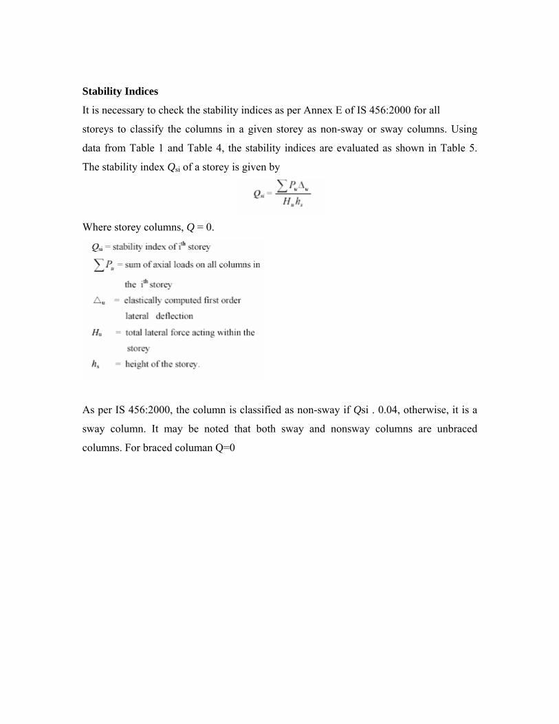
Stability Indices
It is necessary to check the stability indices as per Annex E of IS 456:2000 for all
storeys to classify the columns in a given storey as non-sway or sway columns. Using
data from Table 1 and Table 4, the stability indices are evaluated as shown in Table 5.
The stability index Qsi of a storey is given by
Where storey columns, Q = 0.
As per IS 456:2000, the column is classified as non-sway if Qsi . 0.04, otherwise, it is a
sway column. It may be noted that both sway and nonsway columns are unbraced
columns. For braced columan Q=0


CHAPTER-7
DESIGN OF BEAM

Design of Selected Beams
The design of one of the exterior beam B2001-B2002-B2003 at level 2 along Xdirection
is illustrated here.
General requirements
The flexural members shall fulfil the following general requirements.
(IS 13920; Clause 6.1.2)
Bending Moments and Shear Forces
The end moments and end shears for six basic load cases obtained from computer
analysis are given in Tables 6 and 7. Since earthquake load along Z-direction (EZTP and
EZTN) induces very small moments and shears in these beams oriented along the X-
direction, the same can be neglected from load combinations. Load combinations 6 to 9,
14 to 17, and 22 to 25 are thus not considered for these beams. Also, the effect of positive

torsion (due to accidental eccentricity) for these beams will be more than that of negative
torsion. Hence, the combinations 3, 5, 11, 13, 19 and 21 will not be considered in design.
Thus, the combinations to be used for the design of these beams are 1, 2, 4, 10, 12, 18
and 20. The software employed for analysis will however, check all the combinations for
the design moments and shears. The end moments and end shears for these seven load
combinations are given in Tables 8 and 9. Highlighted numbers in these tables indicate
maximum values.
From the results of computer analysis, moment envelopes for B2001 and B2002 are
drawn in Figures 4 (a) and 4 (b) for various load combinations, viz., the combinations 1,
2, 4,10,12,18 and 20. Design moments and shears at various locations for beams B2001-
B2002–B2003 are given in Table 10.
To get an overall idea of design moments in beams at various floors, the design moments
and shears for all beams in frame A-A are given in Tables 11 and 12. It may be noted that
values of level 2 in Tables 11 and 12 are given in table 10.
:
END MOMENTS FOR BASIC LOAD CASES:
TABLE:6
Sl No. LOAD
CASE.
B2001 B2002 B2003
LEFT. RIGHT. LEFT. RIGHT. LEFT. RIGHT.
1. DL. 127.95 -177.80 189.96 -198.05 150.95 -127.95
2. IL/LL. 20.18 -30.85 59.81 -59.81 31.85 -20.18
3. EXTP. -265.96 -243.66 -217.41 -217.4 -238.9 -263.90
4. EXTN. -218.03 -198.34 -182.83 -182.73 -197.2 -218.05
5. EZTP. -41.28 -40.25 -38.32 -38.2 -39.38 -43.37
6. EZTN. 36.39 34.61 30.69 31.8 32.00 31.99
Sign Convention:Anti-Clockwise Moment.(+).
Clockwise Moment.(-).

END SHEARS FOR BASIC LOAD CASES:
TABLE:7
Sl No. LOAD
CASE
B2001 B2002 B2003
LEFT RIGHT LEFT RIGHT LEFT RIGHT
1 DL 109.04 119.71 140.07 140.07 119.71 109.04
2 IL/LL 17.19 20.23 37.5 37.5 20.23 17.19
3 EXTP -90.75 90.75 -82.64 82.64 -90.76 90.76
4 EXTN -80.7 80.7 -73.95 73.95 -80.7 80.7
5 EZTP -34.74 34.74 -34.34 34.34 -35.3 35.3
6 EZTN 34.8 -34.8 33.90 -33.90 34.24 -34.24
Sign Convention:Upward Force(+)’
Downward Force(-).
FACTORED END MOMENTS(KNM):
TABLE:8
COMB.NO. LOAD
COMBINATIONS.
B2001 B2002 B2003
LEFT RIGHT LEFT RIGHT LEFT RIGHT
1 1.5(DL+IL) 204.20 -
281.70
371.66 -
371.66
281.71 -
204.21
2 1.2(DL+IL+EXTP) -
148.34
-
508.42
36.43 -558.2 -57.72 -475.1
3 1.2(DL+IL+EXTN) -94.68 -459.6 81.53 -
513.12
-8.9 -421.4
4 1.2(DL+IL-EXTP) 475 57.7 558.2 -36.44 508.44 148.38
5 1.2(DL+IL-EXTN) 421.4 8.87 513.12 -81.53 459.6 94.7

6 1.2(DL+IL+EZTP) 117.42 -270.1 253.74 -
340.76
178.8 -213
7 1.2(DL+IL+EZTN) 204.6 -187.4 332.82 -
261.68
261.9 -125.8
8 1.2(DL+IL-EZTP) 209.3 -
180.66
340.9 -253.9 271.42 -113.7
9 1.2(DL+IL-EZTN) 122.1 -
263.29
261.83 -
332.96
188.8 -
200.93
10 1.5(DL+EXTP) -212.7
-590
.7
-42.68
-609
.54
-116.9
-566
.6
11 1.5(DL+EXTN) -
145.62
-
529.71
13.69 -
553.18
-55.9 -499.5
12 1.5(DL-EXTP)
566.
5
116.9 60
9.5
42.66
590.
8
212.7
13 1.5(DL-EXTN) 499.47 55.86 553.2 -13.7 529.7 145.65
14 1.5(DL+EZTP) 119.5 -292.8 228.96 -
337.74
179.36 -
238.98
15 1.5(DL+EZTN) 228.51 -
189.51
327.81 -238.9 282.63 -
129.96
16 1.5(DL-EZTP) 234.35 -
181.05
337.92 -
229.14
294.5 -
114.87
17 1.5(DL-EZTN) 125.34 -
284.34
239.07 -328 191.22 -
223.89
18 (0.9DL+1.5EXTP)
-283
.47
-496
-156
.05
-
496.16
-211
.7
-495.8
19 (0.9DL+1.5EXTN) -
216.39
-
434.94
-99.68 -439.8 -150.6 -
428.73

20 (0.9DL-1.5EXTP) 495.78
211.
66 496.18
156.
03
496
283.
5
21 (0.9DL-1.5EXTN) 428.7 150.63 439.8 99.68 435 216.42
22 (0.9DL+1.5EZTP) 48.05 -
198.03
115.58 -
224.36
84.6 -
168.21
23 (0.9DL+1.5EZTN) 157.74 -94.74 214.43 -125.5 187.86 -59.19
24 (0.9DL-1.5EZTP) 163.6 -86.28 224.54 -
115.76
199.7 -44.1
25 (0.9DL-1.5EZTN) 54.57 -
189.57
125.7 -214.6 96.45 -
153.12
FACTORED END SHEARS:
TABLE:9
COMBINATIO
N NO:
LOAD
COMBINATION
B200
1
B200
2
B200
3
LEFT RIGH
T
LEFT RIGH
T
LEFT RIGH
T
1 1.5(DL+IL) 189.3
5
210.03 267.3 266.34 210 189.35
2 1.2(DL+IL+EXT
P)
42.58 276.92 113.9
2
312.25 59.12 260.39
4 1.2(DL+IL-
EXTP)
260.3
8
59.12 312.2
5
113.92 276.9
4
42.56
10 1.5(DL+EXTP) 27.44
315.
69 86.15
334
43.43
299.
7

12 1.5(DL-EXTP)
299.
7
43.44
334
86.15
315.
7
27.4
18 (0.9DL+1.5EXT
P)
-38 243.86 2.1 250 -28.4 234.28
20 (0.9DL-
1.5EXTP)
234.2
6
-28.39 250 2.1 243.9 -38
Sign Convention:Upward Force(+)’
Force Downward (-).

DESIGN MOMENTS AND SHEARS AT VARIOUS LOCATIONS:
Table-10
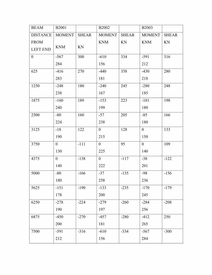
BEAM B2001 B2002 B2003
DISTANCE
FROM
LEFT END
MOMENT
KNM
SHEAR
KN
MOMENT
KNM
SHEAR
KN
MOMENT
KNM
SHEAR
KN
0 -567
284
300 -610
156
334 -591
212
316
625 -416
283
270 -440
181
358 -430
218
280
1250 -248
238
180 -240
167
245 -280
185
248
1875 -160
240
189 -153
199
223 -181
180
198
2500 -80
224
160 -57
238
205 -85
180
166
3125 -18
190
122 0
215
128 0
150
133
3750 0
130
-111 0
225
95 0
140
109
4375 0
140
-138 0
222
-117 -38
201
-122
5000 -80
180
-166 -37
258
-135 -98
236
-156
5625 -151
178
-190
-133
200
-235 -170
245
-179
6250 -278
190
-224 -279
197
-260 -284
256
-208
6875 -450
200
-270 -457
181
-280 -412
265
250
7500 -591
212
-316 -610
156
-334 -567
284
-300


Longitudinal Reinforcement
Consider mild exposure and maximum 10 mm diameter two-legged hoops. Then clear
cover to main reinforcement is 20 +10 = 30 mm. Assume 25 mm diameter bars at top
face and 20 mm diameter bars at bottom face. Then, d = 532 mm for two layers and 557
mm for one layer at top; d = 540 mm for two layers and 560 mm for one layer at bottom.
Also consider d’/d = 0.1 for all doubly reinforced sections.
Design calculations at specific sections for flexure reinforcement for the member B2001
are shown in Table 13 and that for B2002 are tabulated in Table 14. In tables 13 and 14,
the design moments at the face of the support, i.e., 250 mm from the centre of the support
are calculated by linear interpolation between moment at centre and the moment at 625
mm from the centre from the table 10. The values of pc and pt have been obtained from
SP: 16. By symmetry, design of beam B2003 is same as that of B2001. Design bending
moments and required areas of reinforcement are shown in Tables 15 and 16. The
underlined steel areas are due to the minimum steel requirements as per the code. Table
17 gives the longitudinal reinforcement provided in the beams B2001, B 2002 and
B2003.


At A and D, as per requirement of Table 14, 5-20 # bars are sufficient as bottom bars,
though the area of the compression reinforcement then will not be equal to 50% of the
tension steel as required by Clause 6.2.3 of IS 13920:1993. Therefore, at A and D, 6-20 #
are provided at bottom. The designed section is detailed in Figure.6. The top bars at
supports are extended in the spans for a distance of (l /3) = 2500 mm.
Check for reinforcement
(a) Minimum two bars should be continuous at top and bottom. Here, 2–25 mm # (982
mm2) are continuous throughout at top; and 5–20 mm # (1 570 mm2) are continuous
throughout at bottom. Hence, ok.

Provided reinforcement is more. Hence, ok.
(IS 13920; Clause 6.2.2)
Maximum steel ratio on any face at any section should not exceed 2.5, i.e.,
Provided reinforcement is less. Hence ok.
(IS 13920; Clause 6.2.3)
The positive steel at a joint face must be at least equal to half the negative steel at that
face.
Joint A
Half the negative steel = 2
3437 1718 mm2
Positive steel = 1884 mm2 > 1718 mm2
Hence, ok.
Joint B
Half the negative steel = 2
3437 1718 mm2
Positive steel = 1 884 mm2 > 1 718 mm2
Hence, ok.
(IS 13920; Clause 6.2.4)
Along the length of the beam,
Ast at top or bottom ≥ Ý 0.25 Ast at top at joint A and B
Ast at top or bottom ≥ Ý 0.25 × 3 437
≥ Ý 859 mm2
Hence, ok.

(IS 13920; Clause 6.2.5)
At external joint, anchorage of top and bottom bars = Ld in tension + 10 db.
Ld of Fe 415 steel in M25 concrete = 40.3 db
Here, minimum anchorage = 40.3 db + 10 db = 50.3 db. The bars must extend 50.3 db
(i.e. 50.3 x 25 = 1258 mm, say 1260 mm for 25 mm diameter bars and 50.3 x 20 = 1006
mm, say 1010 mm for 20 mm diameter bars) into the column. At internal joint, both face
bars of the beam shall be taken continuously through the column.
Web reinforcements
Vertical hoops (IS: 13920:1993, Clause 3.4 and Clause 6.3.1) shall be used as shear
reinforcement.
Hoop diameter ≥Ý 6 mm
≥ Ý 8 mm if clear span exceeds 5 m. (IS 13920:1993; Clause 6.3.2)
Here, clear span = 7.5 – 0.5 = 7.0 m.
Use 8 mm (or more) diameter two-legged hoops.
The moment capacities as calculated in Table 18 at the supports for beam B2001 and
B2003 are:
kNmkNmM Asu 321M 321 Bs
u ==
kNmkNmM AHu 568M 568 Bh
u ==
The moment capacities as calculated in Table 18 at the supports for beam B2002 are:
kNmkNmM Asu 321M 321 Bs
u ==
kNmkNmM AHu 585M 585 Bh
u ==
1.2 (DL+LL) for U.D.L. load on beam B2001 and B2003.
= 1.2 (30.5 + 5) = 42.6 kN/m.
1.2 (DL+LL) for U.D.L. load on beam B2002
= 1.2 (26.1 + 0) = 31.3 kN/m.
1.2 (DL+LL) for two point loads at third points on beam B2002
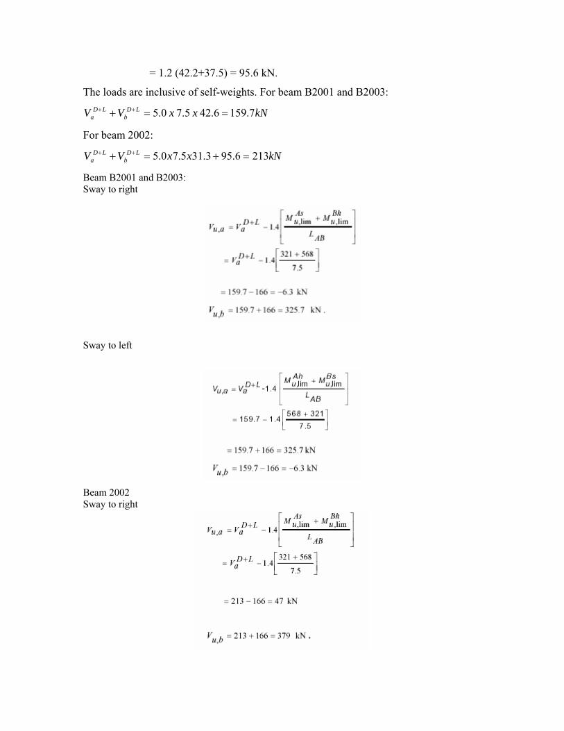
= 1.2 (42.2+37.5) = 95.6 kN.
The loads are inclusive of self-weights. For beam B2001 and B2003:
kNxxVV LDb
LDa 7.1596.42 5.7 0.5 ==+ ++
For beam 2002:
kNxxVV LDb
LDa 2136.953.315.70.5 =+=+ ++
Beam B2001 and B2003: Sway to right
Sway to left
Beam 2002 Sway to right

Sway to left
Maximum design shear at A = 379 kN. Maximum design shear at B = 379 kN.

Design Example of a Building
Maximum shear forces for various cases from analysis are shown in Table 19(a). The
shear force to be resisted by vertical hoops shall be greater of:
i) Calculated factored shear force as per analysis.
ii) ii) Shear force due to formation of plastic hinges at both ends of the beam
plus the factored gravity load on the span.
The design shears for the beams B2001 and B2002 are summarized in Table 19.

As per Clause 6.3.5 of IS 13920:1993,the first stirrup shall be within 50 mm from the
joint face. Spacing, s, of hoops within 2 d (2 x 532 = 1064 mm) from the support shall
not exceed:
(a) d/4 = 133 mm
(b) 8 times diameter of the smallest longitudinal bar = 8 x 20 = 160 mm
Hence, spacing of 133 mm c/c governs. Elsewhere in the span, spacing,
Maximum nominal shear stress in the beam
The proposed provision of two-legged hoops and corresponding shear capacities of the
sections are presented in Table 20.

Note: The shear resistance of concrete is neglected. The designed beam is detailed in
Figure 6.

CHAPTER-8
DESIGN OF COLUMN

Design of Selected Columns
Here, design of column C2 of external frame AA is illustrated. Before proceeding to the
actual design calculations, it will be appropriate to briefly discuss the salient points of
column design and detailing.
Design:
The column section shall be designed just above and just below the beam column joint,
and larger of the two reinforcements shall be adopted. This is similar to what is done for
design of continuous beam reinforcements at the support. The end moments and end
shears are available from computer analysis. The design moment should include:
(a) The additional moment if any, due to long column effect as per clause 39.7 of IS
456:2000.
(b) The moments due to minimum eccentricity as per clause 25.4 of IS 456:2000.
All columns are subjected to biaxial moments and biaxial shears.
The longitudinal reinforcements are designed for axial force and biaxial moment as per
IS: 456.
Since the analysis is carried out considering centre-line dimensions, it is necessary to
calculate the moments at the top or at the bottom faces of the beam intersecting the
column for economy. Noting that the B.M. diagram of any column is linear, assume that
the points of contraflexure lie at 0.6 h from the top or bottom as the case may be; where h
is the height of the column. Then obtain the column moment at the face of the beam by
similar triangles. This will not be applicable to columns of storey 1 since they do not
have points of contraflexure.
Referring to figure 9, if M is the centre-line moment in the column obtained by analysis,
its moment at the beam face will be:
0.9 M for columns of 3 to 7th storeys, and
0.878 M for columns of storey 2.

Critical load combination may be obtained by inspection of analysis results. In the
present example, the building is symmetrical and all columns are of square section. To
obtain a trial section, the following procedure may be used:
Let a rectangular column of size b x D be subjected to Pu, Mux (moment about major
axis) and Muz (moment about minor axis). The trial section with uniaxial moment is
obtained for axial load and a combination of moments about the minor and major axis.
For the trial section
Determine trial reinforcement for all or a few predominant (may be 5 to 8) combinations
and arrive at a trial section. It may be emphasized that it is necessary to check the trial
section for all combinations of loads since it is rather difficult to judge the governing
combination by visual inspection.
Detailing:
Detailing of reinforcement as obtained above is discussed in context with Figure 10.
Figure 10(a) shows the reinforcement area as obtained above at various column-floor

joints for lower and upper column length. The areas shown in this figure are fictitious and
used for explanation purpose only.
The area required at the beam-column joint shall have the larger of the two values, viz.,
for upper length and lower length. Accordingly the areas required at the joint are shown
in Figure. 10 (b).
Since laps can be provided only in the central half of the column, the column length for
the purpose of detailing will be from the centre of the lower column to the centre of the
upper column. This length will be known by the designation of the lower column as
indicated in Figure 9(b).
It may be noted that analysis results may be such that the column may require larger
amounts of reinforcement in an upper storey as compared to the lower storey. This may
appear odd but should be acceptable.
Effective length calculations:
Effective length calculations are performed in accordance with Clause 25.2 and Annex E
of IS 456:2000.
Stiffness factor
Stiffness factors ( I / l ) are calculated in Table 21. Since lengths of the members about
both the bending axes are the same, the suffix specifying the directions is dropped.
Effective lengths of the selected columns are calculated in Table 22 and Table 23.

Determination of trial section:
The axial loads and moments from computer analysis for the lower length of column 202
are shown in Table 24 and those for the upper length of the column are shown in Table
26.In these tables, calculations for arriving at trial sections are also given. The
calculations are performed as described in Section 1.11.1 and Figure 10. Since all the
column are short, there will not be any additional moment due to slenderness. The
minimum eccentricity is given by

(IS 456:2000, Clause 25.4) For lower height of column, L = 4,100 – 600
Similarly, for all the columns in first and second storey, ex,min = ey,min = 25 mm.
For upper height of column, L = 5,000 – 600=4,400 mm.
For all columns in 3rd to 7th storey.
For column C2 in all floors, i.e., columns C102,
C202, C302, C402, C502, C602 and C702,
fck =

Calculations of Table 25 and 27 are based on uniaxial moment considering steel on two
opposite faces and hence, Chart 32 of SP: 16 is used for determining the trial areas.
Reinforcement obtained for the trial section is equally distributed on all four sides. Then,
Chart 44 of SP: 16 is used for checking the column sections, the results being
summarized in Tables 25 and 27.
The trial steel area required for section below joint C of C202 (from Table 25) is
p/fck = 0.105 for load combination 1 whereas that for section above joint C, (from Table
27) is p/fck = 0.11 for load combination 12.
Trial steel areas required for column lengths C102, C202, C302, etc., can be determined
in a similar manner. The trial steel areas required at various locations are shown in Figure
10(a). As described in Section 1.12. the trial reinforcements are subsequently selected
and provided as shown in figure 11 (b) and figure 11 (c). Calculations shown in Tables
25 and 27 for checking the trial sections are based on provided steel areas.
For example, for column C202 (mid-height of second storey to the mid-height of third
storey), provide 8-25 # + 8-22 # = 6968 mm2, equally distributed on all faces.
Calculations given in Tables 24 to 27 are self-explanatory
.

TABLE 24 TRIAL SECTION BELOW JOINT C
Comb.
Centreline moment
Moment at face Cal. Ecc.,mm Des. Ecc.,mm
P’u
M’uz
No.
Pu, kN
ex ez edx edz
Mux, kNm
Muz, kNm
Mux, kNm
Muz, kNm
Mux, kNm
Muz, kNm
1 4002 107 36 93.946 31.608 23.47 7.90 25.00 25.00 100 100 4002 200 0.64 0.06 0.105 2 3253 89 179 78.14 157.16 24.02 48.31 25.00 48.31 81 157 3253 238 0.52 0.08 0.083 3 3225 83 145 72.87 127.31 22.60 39.48 25.00 39.48 81 127 3225 208 0.52 0.07 0.078 4 3151 82 238 72.00 208.96 22.85 66.32 25.00 66.32 79 209 3151 288 0.50 0.09 0.083 5 3179 88 203 77.26 178.23 24.30 56.07 25.00 56.07 79 178 3179 258 0.51 0.08 0.08 6 2833 17 12 14.93 10.54 5.27 3.72 25.00 25.00 71 71 2833 142 0.45 0.05 0.042 7 2805 23 45 20.19 39.51 7.20 14.09 25.00 25.00 70 70 2805 140 0.45 0.04 0.038 8 3571 189 46 165.94 40.39 46.47 11.31 46.47 25.00 166 89 3571 255 0.57 0.08 0.096 9 3598 195 13 171.21 11.41 47.58 3.17 47.58 25.00 171 90 3598 261 0.58 0.08 0.1 10 3155 65 242 57.07 212.48 18.09 67.35 25.00 67.35 79 212 3155 291 0.50 0.09 0.083 11 3120 58 199 50.92 174.72 16.32 56.00 25.00 56.00 78 175 3120 253 0.50 0.08 0.079 12 3027 57 279 50.05 244.96 16.53 80.93 25.00 80.93 76 245 3027 321 0.48 0.10 0.097 13 3063 65 236 57.07 207.21 18.63 67.65 25.00 67.65 77 207 3063 284 0.49 0.09 0.082 14 2630 68 3 59.70 2.63 22.70 1.00 25.00 25.00 66 66 2630 132 0.42 0.04 0.024 15 2596 75 38 65.85 33.36 25.37 12.85 25.37 25.00 66 65 2596 131 0.42 0.04 0.024 16 3552 190 40 166.82 35.12 46.97 9.89 46.97 25.00 167 89 3552 256 0.57 0.08 0.1 17 3587 198 1 173.84 0.88 48.47 0.24 48.47 25.00 174 90 3587 264 0.57 0.08 0.1 18 1919 41 249 36.00 218.62 18.76 113.92 25.00 113.92 48 219 1919 267 0.31 0.09 0.04 19 1883 33 206 28.97 180.87 15.39 96.05 25.00 96.05 47 181 1883 228 0.30 0.07 0.023 20 1791 33 272 28.97 238.82 16.18 133.34 25.00 133.34 45 239 1791 284 0.29 0.09 0.038 21 1826 40 229 35.12 201.06 19.23 110.11 25.00 110.11 46 201 1826 247 0.29 0.08 0.03 22 1394 92 10 80.78 8.78 57.95 6.30 57.95 25.00 81 35 1394 116 0.22 0.04 negative 23 1359 100 31 87.80 27.22 64.61 20.03 64.61 25.00 88 34 1359 122 0.22 0.04 negative 24 2316 166 32 145.75 28.10 62.93 12.13 62.93 25.00 146 58 2316 204 0.37 0.07 0.038 25 2351 173 9 151.89 7.90 64.61 3.36 64.61 25.00 152 59 2351 211 0.38 0.07 0.04


Design of Transverse reinforcement
Three types of transverse reinforcement (hoops or ties) will be used. These are: i) General
hoops: These are designed for shear as per recommendations of IS 456:2000 and
IS 13920:1993.
ii) Special confining hoops, as per IS 13920:1993 with spacing smaller than that of the
general hoops
iii) Hoops at lap: Column bars shall be lapped only in central half portion of the column.
Hoops with reduced spacing as per IS 13920:1993 shall be used at regions of lap splicing.
Design of general hoops
(A) Diameter and no. of legs
Rectangular hoops may be used in rectangular column. Here, rectangular hoops of 8 mm diameter are used.
The spacing of bars is (395/4) = 98.75 mm, which is more than 75 mm. Thus crossties on
all bars are required
(IS 456:2000, Clause 26.5.3.2.b-1)
Provide 3 no open crossties along X and 3 no open crossties along Z direction. Then total
legs of stirrups (hoops) in any direction = 2 +3 = 5.
(B) Spacing of hoops
As per IS 456:2000, Clause 26.5.3.2.(c), the pitch of ties shall not exceed:
(i) b of the column = 500 mm
(ii) 16 φmin (smallest diameter) = 16 x 20 = 320 mm
(iii) 300 mm …. (1)
The spacing of hoops is also checked in terms of maximum permissible spacing of shear
Reinforcement given in IS 456:2000, Clause 26.5.1.5
b x d = 500 x 450 mm. Using 8# hoops,
Asv = 5 x 50 = 250 mm2.

The spacing should not exceed
(requirement for minimum shear reinforcement)
= mm 451.3
(ii) 0.75 d = 0.75 X 450 = 337.5 mm
(iii) 300 mm; i.e., 300 mm … ……………………………………………….(2)
As per IS 13920:1993, Clause 7.3.3,
Spacing of hoops . b/2 of column
= 500 / 2 = 250 mm …………………………………………………………. (3)
From (1), (2) and (3), maximum spacing of
stirrups is 250 mm c/c.
Design Shear
As per IS 13920:1993, Clause 7.3.4, design shear for columns shall be greater of the
followings:
(a) Design shear as obtained from analysis
For C202, lower height, Vu = 161.2 kN, for load combination 12.
For C202, upper height, Vu = 170.0 kN, for load combination 12.
For C202, lower height, using sections of B2001 and B2002 lim ,

For C202, upper height, assuming same design as sections of B2001 and B2002.
Than
Design shear is maximum of (a) and (b). Then, design shear Vu = 390 kN. Consider the
column as a doubly reinforced beam, b = 500 mm and d = 450 mm. As = 0.5 Asc = 0.5 x 6 968 = 3 484 mm2.
For load combination 12, Pu = 3,027 kN for lower length and Pu = 2,547 kN for upper
length.
Than
Tableδ =1.5

Use 200 mm spacing for general ties.
1.11.3.3. Design of Special Confining Hoops:
As per Clause 7.4.1 of IS 13920:1993, special confining reinforcement shall be provided over a length l0, where flexural yielding may occur. l0 shall not be less than
(i) D of member, i.e., 500 mm
Provide confining reinforcement over a length of 600 mm in C202 and 800 mm in C302
from top and bottom ends of the column towards mid height .
As per Clause 7.4.2 of IS 13920:1993, special confining reinforcement shall extend for minimum 300 mm into the footing. It is extended for 300 mm as shown in Figure 12. As per Clause 7.4.6 of IS 13920:1993, the spacing, s, of special confining reinforcement shall extend for minimum 300 mm into the footing. It is extended for 300 mm as shown in Figure 12. As per Clause 7.4.6 of IS 13920:1993, the spacing, s, of special confining reinforcement is governed by: s ≤ 0.25 D = 0.25 x 500 = 125 mm≤ 75 mm ≤. 100mm i.e. Spacing = 75 mm to 100 mm c/c...… (1) As per Clause 7.4.8 of IS 13920:1993, the area of special confining reinforcement, Ash, is given by:

Here average h referring to fig 12 is
Provide 8 mm # 5 legged confining hoops in both the directions @ 100 mm c/c.

Design of hoops at lap As per Clause 7.2.1 of IS 13920:1993, hoops shall be provided over the entire splice
length at a spacing not exceeding 150 mm centres Moreover, not more than 50 percent of
the bars shall be spliced at any one section. Splice length = Ld in tension = 40.3 db.
Consider splicing the bars at the centre (central half ) of column 302. Splice length =
40.3 x 25 = 1008 mm, say 1100 mm. For splice length of 40.3 db, the spacing of hoops is
reduced to 150 mm. Refer to Figure 12.
Column Details
The designed column lengths are detailed in Figure 12. Columns below plinth require
smaller areas of reinforcement; however, the bars that are designed in ground floor
(storey 1) are extended below plinth and into the footings. While detailing the shear
reinforcements, the lengths of the columns for which these hoops are provided, are
slightly altered to provide the exact number of hoops. Footings also may be cast in M25
grade concrete.

CHAPTER-9 DESIGN OF FOOTING

Design of footing: (M20 Concrete):
It can be observed from table 24 and table 26 that load combinations 1 and 12 are
governing for the design of column. These are now tried for the design of footings also.
The footings are subjected to biaxial moments due to dead and live loads and uniaxial
moment due to earthquake loads. While the combinations are considered, the footing is
subjected to biaxial moments. Since this building is very symmetrical, moment about
minor axis is just negligible. However, the design calculations are performed for biaxial
moment case. An isolated pad footing is designed for column C2. Since there is no limit
state method for soil design, the characteristic loads will be considered for soil design.
These loads are taken from the computer output of the example building. Assume
thickness of the footing pad D = 900 mm.
(a) Size of footing:
Case 1:
Combination 1, i.e., (DL + LL)
P = (2291 + 608) = 2899 kN
Hx = 12 kN, Hz = 16 kN
Mx = 12 kNm, Mz = 6 kNm.

At the base of the footing
P = 2899 kN
P’ = 2899 + 435 (self-weight) = 3334 kN, assuming self-weight of footing to be 15%
of the column axial loads (DL + LL).
Mx1 = Mx + Hy .D
= 12 + 16 . 0.9 = 26.4 kNm
Mz1 = Mz +Hy .D
= 6 + 12 . 0.9 = 18.8 kNm.
For the square column, the square footing shall be adopted. Consider 4.2 m . 4.2 m size.
A = 4.2 . 4.2 = 17.64 m2
Maximum soil pressure
= 189 + 2.14 + 1.52
= 192.66 kN/m2 < 200 kN/m2
Minimum soil pressure
= 189 – 2.14 – 1.52
= 185.34 kN/m2 > 0 kN/m2.
Case 2:
Combination 12, i.e., (DL - EXTP)
Permissible soil pressure is increased by 25%.
i.e., allowable bearing pressure = 200 .1.25
P = (2291 - 44) = 2247 kN
Hx = 92 kN, Hz = 13 kN
Mx = 3 kNm, Mz = 216 kNm. At the base of the footing
P = 2247 kN

P’ = 2247 + 435 (self-weight) = 2682 kN.
Mx1 = Mx + Hy .D
= 3 + 13 . 0.9 = 14.7 kNm
Mz1 = Mz +Hy .D
= 216 + 92 . 0.9 = 298.8 kNm.
Maximum soil pressure
= 152.04 + 1.19 + 24.2
= 177.43 kN/m2 < 250 kN/m2.
Minimum soil pressure
= 152.04 - 1.19 – 24.2
= 126.65 kN/m2 > 0 kN/m2.
Case 1 governs.
In fact all combinations may be checked for maximum and minimum pressures and
design the footing for the worst combination. Design the footing for combination 1, i.e.,
DL +LI
Factored upward pressures for design of the footing with biaxial moment are as follows.
For Mx

Since there is no much difference in the values, the footing shall be designed for Mz for
an upward pressure of 250 kN/m2 on one edge and 167 kN/m2 on the opposite edge of
the footing.
The same design will be followed for the other direction also.
Net upward forces acting on the footing are shown in fig. 13.
(b) Size of pedestal: A pedestal of size 800 mm . 800 mm is used. For a pedestal
A = 800 . 800 = 640000 mm2
Z = 3 2 mm 85333333 800 800

For case 1
For case 2
Since 33.33 % increase in stresses is permitted due to the presence of EQ loads,
equivalent stress due to DL + LL is
From (1) and (2) consider q0 = 5.4 N/mm2. For the pedestal
This gives
Projection of the pedestal = 150 mm
Depth of pedestal = 150 . 4.762 = 714.3 mm.
Provide 800 mm deep pedestal.
(c) Moment steel:
Net cantilever on x-x or z-z
= 0.5(4.2-0.8) = 1.7 m.
Refer to fig. 13.

For the pad footing, width b = 4200 mm
For M20 grade concrete, Qbal = 2.76.
Balanced depth required
Try a depth of 900 mm overall. Larger depth may be required for shear design. Assume 16 mm diameter bars. dx = 900 – 50 – 8 = 842 mm
dz = 842 – 16 = 826 mm.
Average depth = 0.5(842+826) = 834 mm. Design for z direction.
(Clause 34.5, IS: 456)
Provide 28 no. 16 mm diameter bars.
(d) Development length:
HYSD bars are provided without anchorage.
Development length = 47 . 16 = 752 mm
Anchorage length available
= 1700 – 50 (cover) = 1650 mm … (o.k.)
(e) One-way shear:
About z1-z1
At d = 826 mm from the face of the pedestal
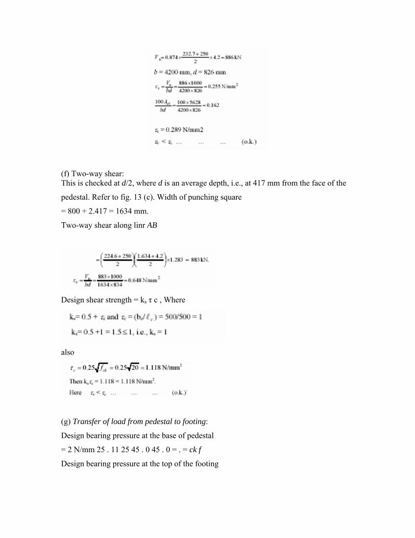
(f) Two-way shear: This is checked at d/2, where d is an average depth, i.e., at 417 mm from the face of the
pedestal. Refer to fig. 13 (c). Width of punching square
= 800 + 2.417 = 1634 mm.
Two-way shear along linr AB
Design shear strength = ks τ c , Where
also
(g) Transfer of load from pedestal to footing:
Design bearing pressure at the base of pedestal
= 2 N/mm 25 . 11 25 45 . 0 45 . 0 = . = ck f
Design bearing pressure at the top of the footing

Thus design bearing pressure = 11.25 N/mm2.
Actual bearing pressure for case 1
= 1.5 .q01= 1.5 . 5.06 = 7.59 N/mm2.
Actual bearing pressure for case 2
= 1.2 .q02= 1.2 . 7.18 = 8.62 N/mm2.
Thus dowels are not required.
Minimum dowel area = (0.5/100) . 800 . 800
= 3200 mm2.
Area of column bars = 7856 mm2
It is usual to take all the bars in the footing to act as dowel bars in such cases.
Minimum Length of dowels in column = Ld of column bars
= 28 . 25 = 700 mm.
Length of dowels in pedestal = 800 mm.
Length of dowels in footing = D + 450 = 900 + 450 = 1350 mm.
This includes bend and ell of the bars at the end. The Dowels are lapped with column
bars in central half length of columns in ground floors. Here the bars are lapped at mid
height of the column width 1100 mm lapped length.
Total length of dowel (Refer to fig. 12)
= 1350 + 800 + 600 + 1750 + 550
= 5050 mm.
Note that 1100 mm lap is given about the midheight of the column.
(h) Weight of the footing:
= 4.2 . 4.2 . 0.9 . 25 = 396.9 KN(assumed)
< 4 35KN.

Conclusions
1. The tasks of providing absolute seismic safety for the residents inhabiting the most earthquake-prone regions are far from being solved. However, new regulations on construction that contribute to earthquake disaster mitigation have been introduced and implemented in accordance with world practice. These regulations are based on experience of past earthquakes and results of special researches, summarized in adequate documents of many states.
The regulations of each country depend on local experience in seismic design,
however they have some common guidance. In the regulations adopted for implementation in India the following factors have been found to be critically important in the design and construction of seismic resistant buildings:
- To select sites for construction that are the most favorable in terms of the
frequency of occurrence and the likely severity of ground shaking and ground failure;
- To apply structural-spatial solutions that provide symmetry and regularity in the distribution of mass and stiffness in plan and in elevation;
- To implement the design of building elements and joints between them in accordance with analysis that take into account the structural requirements;
- To provide high quality of construction to ensure good performance during future earthquakes.
Researchers indicates that compliance with the above-mentioned requirements will
contribute significantly to disaster mitigation, regardless of the intensity of the seismic loads and specific features of the earthquakes.
The modifications in construction and design that have been introduced increase
seismic reliability of the buildings and seismic safety for human life. At the same time, current regulations cannot be considered as final. As new data
become available they have to be defined more precisely and new provisions have to be added to meet the needs.
The conducted analysis illustrated that the main reasons of tragic earthquake consequences are to be considered as follows:
- The violations of code requirement on design and construction of structures, and
in some countries – low normative basis of earthquake engineering, in part of legislative force;
- Selection for construction sites if multi-storied buildings – the sites with unfavorable in terms of seismic design soil conditions;
- The Application of simplified procedure for co-ordination and licensing on launching of construction;
- Lack of due quality control of performance construction.
In order to improve seismic safety of residents and to prevent huge property damage caused of earthquake it is necessary:
- To strengthen role of design an construction control by State body; - To design and construct on seismic unfavorable sites only by authority of
appropriate experts’ commission; - To implement widely the test practice and quality control of building material and
elements, used in construction; The buildings of new construction types must be put into operation only after conducting model and real tests;
- To develop guidance on design for buildings of some types (e.g. frame and frame buildings with stiffening core) and to specify series of current seismic code provisions;
- To allow implementation of construction activity only for companies with appropriate license and documents proved the right on conducting certain kinds of works;
- To conduct full-scale investigation of built-up area developments which are located in seismic active regions, and then in accordance with systematization and analysis of investigation results to carry out the measures in order to mitigate consequences of disaster.

References 1.Sinha,S.N.,Reinforced concrete design, Tata McGraw-Hill,New Delhi,1998. 2.Raju Krishna,N., RCC design,New age International publisher,New Delhi,2003. 3.Negi,L.S.,Structural analysis, Tata McGraw-Hill,New Delhi,1984. 4.Norris, Charles., Structural analysis,McGraw-Hill International series,New Delhi,1991. 5.Mallick,Dharam.V.,Protection against earth quake,South Asian publication, New Delhi,1971. 6.Dowrick.J,David.,Earth quake risk reduction,Willey publication,USA,1984. 7.IS:1893(Part-1):2002,Criteria for earth quake resistant design of structure. 8.IS:13920:1993,Ductile detailing of RCC structure subjected to earth quake force. 9.IS:456:2000,Plain and Reinforced code of practice. 10.SP:16,Design Aid for Reinforced concrete to IS:456:2000. 11.SP:34,Detailing to RCC Structure.