guidelines for airfield rubblization
TRANSCRIPT

8/12/2019 Guidelines for Airfield Rubblization
http://slidepdf.com/reader/full/guidelines-for-airfield-rubblization 1/16
GUIDELINES FOR AIRFIELD RUBBLIZATION
By:Mark Buncher, PhD, PEDirector of Engineering
Asphalt Institute2696 Research Park Drive
Lexington, KY 40511USA
Phone: (859) 288-4972, [email protected]
PRESENTED FOR THE2010 FAA WORLDWIDE AIRPORT TECHNOLOGY TRANSFER CONFERENCE
Atlantic City, New Jersey, USA
April 2010

8/12/2019 Guidelines for Airfield Rubblization
http://slidepdf.com/reader/full/guidelines-for-airfield-rubblization 2/16
Buncher 1
ABSTRACT
Airfield Asphalt Pavement Technology Program (AAPTP) Project 04-01 called for thedocumentation of the state of the art in rubblization technology for airfield pavements and fordeveloping guidelines covering project feasibility, thickness design/material characterization,
quality assurance criteria and methods, and construction/equipment issues. The AAPTP 04-01Final Report can be found at www.aaptp.us. This paper is an abbreviated description of the keyfindings from that report.
An extensive review of the literature on rubblization for both highways and airfields wasconducted under this project. A comparison of current rubblization specifications was provided,along with a summary of all airfield rubblization projects known to date.
The combination of thin slabs (less than 9-inches) and weak underlying support (little to nosubbase and soft subgrade that is often saturated) can produce marginal stability and difficulty ineffectively rubblizing the PCC to specified criteria. A suggested criteria and protocol was
developed for assessing the suitability of rubblization as a rehabilitation technique if the concreteslabs are less than 9 inches thick and have weak underlying support. Even when a significant portion of a project is assessed with a moderate to high level of risk, there are a number ofrecommendations and considerations in the planning, design and construction stages to optimizesuccess.
Structural characterization of the rubblized layer is covered; along with other thickness designconsiderations such as minimum overlay thickness. To determine appropriate design modulusvalues for a rubblized layer, the literature was reviewed for studies where back-calculatedmodulus values of rubblized layers (Erub) were determined. In addition, new back-calculationswere performed for several projects, providing a total of 17 unique rubblized sections. Theaverage in-place E
rub value was 205 ksi, with the absolute range being 100-430 ksi.
Quality control and assurance of the rubblization process is addressed, providingrecommendations regarding test strips, test pits and particle-size acceptance criteria. Guidanceon equipment and other issues are also covered.
INTRODUCTION AND BACKGROUND
Rubblization is the process of fracturing the existing Portland Cement Concrete Pavement(PCCP) in-place into small-interconnected pieces that serve as a base course for a new Hot MixAsphalt (HMA) overlay. Rubblizing PCCP should result in the complete elimination of any slabaction and subsequent reflective cracking into the new HMA. For concrete pavement withdistributed steel, such as jointed reinforced concrete pavements (JRCP) and continuouslyreinforced concrete pavement (CRCP), the steel should be ruptured or the concrete-to-steel bondshould generally be broken. Rubblization reduces the existing concrete pavement into a layerthat resembles an aggregate base with a high degree of particle-to-particle interlock and is stifferthan most aggregate base layers. Since there are no hauling or disposal costs and all of theexisting pavement materials remain in-place, rubblization is a very cost-effective rehabilitationmethod. The existing layers below the slabs, such as a aggregate or stabilized base, remain in

8/12/2019 Guidelines for Airfield Rubblization
http://slidepdf.com/reader/full/guidelines-for-airfield-rubblization 3/16
Buncher 2
place to continue providing structural support. Some designers have placed a dense crushedaggregate base layer, or reclaimed HMA or PCC, over the rubblized PCC as a leveling course prior to the HMA. The HMA pavement is placed as a series of lifts, whose total thickness isdetermined in a manner similar to how a new flexible pavement would be designed. The neteffect of rubblizing is to convert a deteriorating rigid pavement system into a new flexible
pavement system.
Rubblization technology and equipment were initially developed to rehabilitate aging highway pavements; however, there is growing interest in using this technology for rehabilitating agingairfield pavements as well. For perspective, of the approximate 50 million square yards of PCCPthat has been rubblized on hundreds of projects in the U.S. this past decade, about 98% has beenon highways and only 2% on airfields. This 2% constitutes roughly 40 airfield projects scatteredacross the U.S. on a wide range of airfield types, from small general aviation to heavy loads.The widespread use and success of rubblization on highways provides the basis for tremendous payback potential when applying this technology to airfields. While rubblization has beendeemed successful on the overwhelming majority of airfields projects, there are still many
questions that remain when applying this technology to airfields. For example, highway PCCPthickness typically ranges between 8 to 12 inches, while airfields can be as thin as 6 inches or asthick as 25 inches. Another area where specific guidance for airfield rubblization is critical is inthickness design, since procedures for designing airfields varies greatly from traditionalempirical highway procedures. While many state highway agencies have their own set of policies, procedures and specifications for using rubblization, these vary considerably from stateto state. For this project, the challenge was to develop rubblization guidelines that areappropriate for the vast multitude of conditions that may exist on airfields across the country.
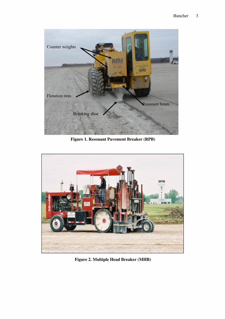
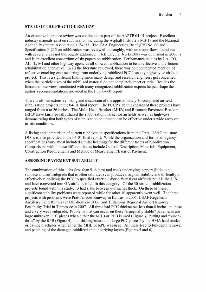
There are two basic types of rubblization equipment; the resonant pavement breaker (RPB) andthe multi-head breaker (MHB). Both types can vary in size and weight depending on the model.The RPB is shown in Figure 1 and the MHB in Figure 2. The RPB is a self-propelled breakingunit that produces low amplitude (1/2-1 inch), high frequency (42-46) impacts per second (hertz)through a massive steel beam, often described as a “giant tuning fork.” The vibrating footrubblizes the concrete pavement in narrow strips as the machine moves forward along theunfractured edge of the pavement. The MHB is both a tractor and breaking unit, consisting ofnumerous pairs of 1,200 lb, 8-inch wide hammers mounted laterally across the breaking unit that produces continuous breakage from side to side. Each hammer pair operates independently anddevelops between 1,000 and 8,000 foot-pounds of energy (depending upon the drop heightselected) and cycles at a rate of 30 to 35 impacts per minute. The MHB travels on unbroken slabsas it moves forward. Production rates for both the RPB and the MHB are generally from 6,000to 8,000 yd2 per unit per work shift, with thick airfield pavements being on the low end of thisrange.
8/12/2019 Guidelines for Airfield Rubblization
http://slidepdf.com/reader/full/guidelines-for-airfield-rubblization 4/16
Buncher 3
Figure 1. Resonant Pavement Breaker (RPB)
Figure 2. Multiple Head Breaker (MHB)
Flotation tires
Counter weights
Breaking shoe
Resonant beam
8/12/2019 Guidelines for Airfield Rubblization
http://slidepdf.com/reader/full/guidelines-for-airfield-rubblization 5/16
Buncher 4
STATE OF THE PRACTICE REVIEW
An extensive literature review was conducted as part of the AAPTP 04-01 project. Excellentindustry manuals exist on rubblization including the Asphalt Institute’s MS-17 and the NationalAsphalt Pavement Association’s IS-132. The FAA Engineering Brief (EB) No. 66 and
Specification P-215 on rubblization was reviewed thoroughly, with no major flaws found butwith several areas not thoroughly addressed. TRB Circular No E-C087 was published in 2006 isand is an excellent consortium of six papers on rubblization. Performance studies by LA, CO,AL, IL, MI and other highway agencies all showed rubblization to be an effective and efficientrehabilitation alternative. In all the literature reviewed, there was no documented mention ofreflective cracking ever occurring from underlying rubblized PCCP on any highway or airfield project. This is a significant finding since many design and research engineers get concernedwhen the particle sizes of the rubblized material do not completely meet criteria. Besides theliterature, interviews conducted with many recognized rubblization experts helped shape theauthor’s recommendations provided in the final 04-01 report.
There is also an extensive listing and discussion of the approximately 30 completed airfieldrubblization projects in the 04-01 final report. The PCCP slab thicknesses of these projects haveranged from 6 to 26 inches. The Multi-Head Breaker (MHB) and Resonant Pavement Breaker(RPB) have fairly equally shared the rubblization market for airfields as well as highways,demonstrating that both types of rubblization equipment can be effective under a wide array onin-situ conditions.
A listing and comparison of current rubblization specifications from the FAA, USAF and stateDOTs is also provided in the 04-01 final report. While the organization and format of agencyspecifications vary, most included similar headings for the different facets of rubblization.Comparisons within these different facets include General Description, Materials, Equipment,Construction Requirements and Method of Measurement/Basis of Payment.
ASSESSING PAVEMENT SUITABILITY
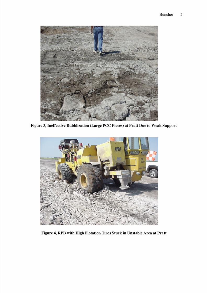
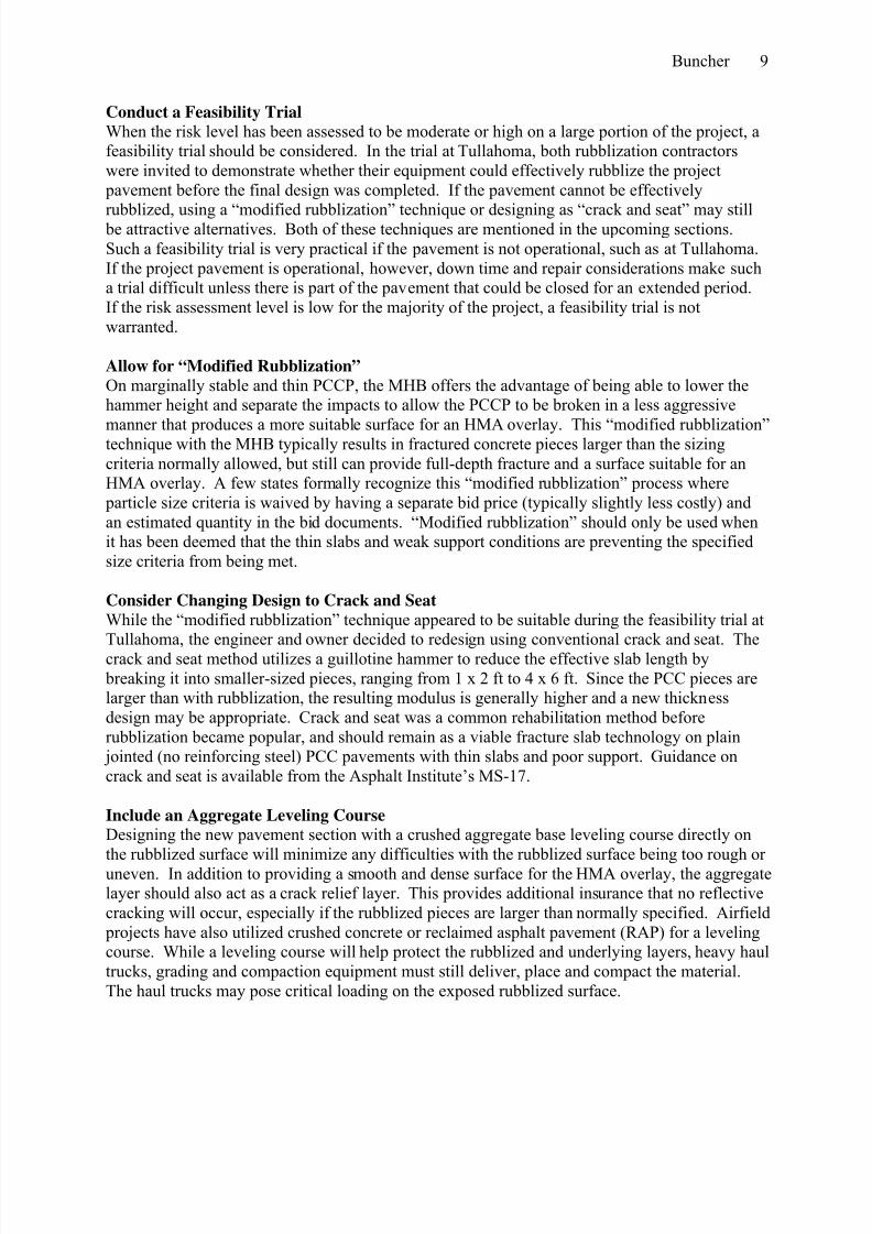
The combination of thin slabs (less than 9-inches) and weak underlying support (little to nosubbase and soft subgrade that is often saturated) can produce marginal stability and difficulty ineffectively rubblizing the PCC to specified criteria. World War II era airfields built in the U.S.and later converted into GA airfields often fit this category. Of the 30 airfield rubblization projects found with this study, 13 had slabs between 6-8 inches thick. On three of these,significant stability problems were reported while the other 10 apparently went well. The three projects with problems were Pratt Airport Runway in Kansas in 2005, USAF KegelmanAuxillary Field Runway in Oklahoma in 2006, and Tullahoma Regional Airport RunwayFeasibility Trial in Tennessee in 2007. All three had PCC thicknesses less than 8 inches, no baseand a very weak subgrade. Problems that can occur on these “marginally stable” pavements arelarge unbroken PCC pieces when either the MHB or RPB is used (Figure 3), rutting and “punch-thrus” by the RPB (Figure 4), and shifting/rotation of large PCC pieces by the HMA haul trucksor paving machines when either the MHB or RPB was used. All these lead to full-depth removaland patching of the damaged rubblized and underlying layers (Figures 5 and 6).
8/12/2019 Guidelines for Airfield Rubblization
http://slidepdf.com/reader/full/guidelines-for-airfield-rubblization 6/16
Buncher 5
Figure 3, Ineffective Rubblization (Large PCC Pieces) at Pratt Due to Weak Support
Figure 4, RPB with High Flotation Tires Stuck in Unstable Area at Pratt

8/12/2019 Guidelines for Airfield Rubblization
http://slidepdf.com/reader/full/guidelines-for-airfield-rubblization 7/16
Buncher 6
Figure 5, Excavation of Ineffective Rubblized Areas at Pratt for Full-depth Patch
Figure 6, Finished Patched Areas Outlined in White at Pratt using Crushed Aggregate

8/12/2019 Guidelines for Airfield Rubblization
http://slidepdf.com/reader/full/guidelines-for-airfield-rubblization 8/16
Buncher 7
The author and his research team developed an evaluation protocol and risk assessment criteriafor potential rubblization projects that contained these marginal support conditions (less than 9”thick PCC, little or no base, and weak and/or saturated subgrade). The evaluation protocoldeveloped was modified from one newly developed by the Texas DOT and the risk assessmentcriteria were modified from the Illinois DOT.
The protocol collects information on the pavement structure through historical records, a visualcondition survey, and in-situ testing that includes ground penetrating radar (GPR), falling weightdeflectometer (FWD), and DCP. The GPR survey estimates pavement layer thicknesses,identifies changes in the pavement structure, and detects locations of wet subgrade or saturatedvoids. The FWD provides data to evaluate the structural condition of the pavement layers andoverall pavement strength at one location relative to others. The DCP data serves for validationof base layer thicknesses and base and subgrade strength conditions. Once the evaluation data iscollected and analyzed, rubblization can be assessed against the criteria in Figure 7. More detailson the analysis are provided in the full report.
Figure 7, Rubblization Assessment Chart for Airfields
This evaluation protocol and chart should be used for evaluating airfield rubblization candidateswhere PCC slabs are less than 9 inches thick and support conditions are suspect. The high riskzone is indicative of areas likely to be problematic, the moderate risk zone of potentially problematic areas, and low risk zone of areas that should rubblize nicely. Airfield pavementswith a substantial granular or stabilized base will fall in the low risk area and are good
Rubblization Assessment Guidance
0
2
4
6
8
10
12
14
16
18
20
0 1 2 3 4 5 6 7 8 9 10
C o n c r e
t e p l u s B a s e
T h
i c k n e s s
High Risk
Low Risk ModerateRisk
Subgrade CBR

8/12/2019 Guidelines for Airfield Rubblization
http://slidepdf.com/reader/full/guidelines-for-airfield-rubblization 9/16
Buncher 8
rubblization candidates. On the other hand, thin slabs with no base and weak subgrade may fallinto the moderate or high risk area. If the PCC plus base thickness is 6-8 inches, and CBRs are10-14 (off the chart), we believe the appropriate risk level is moderate. The risk levels can be plotted versus station number to assess the relative risk over the entire project. The frequency ofFWD and DCP testing, and overall robustness of the evaluation, will depend on a number of
factors, including the level of concern based on current knowledge of in-situ conditions. Thisevaluation procedure allows the design engineer to predict the amount and location of full-depthrepairs before the project starts, and once the rubblization process has started to adjust that prediction for the remainder for the project based on actual ability to rubblize under the knownconditions. Unfortunately, there is little field data to validate the accuracy and recommendedapplication of this chart. As with any new criteria, these guidelines need to be validated and possibly adjusted based on actual field experience. This can only occur with data collected froman evaluation similar to that prescribed here.‘Even on projects where the pavement section appears to be uniform, some areas will rubblizewhile others may not due to subtle differences in subgrade and drainage conditions. It is helpful
to have an estimate of unstable areas and also to know where the weakest support conditionsmay be expected. Pavements with a substantial subbase, or slabs ≥ 9-inches, will not likely be problematic.
After reviewing all the national literature, project history and demonstration projects as part ofthis research, there is no compelling evidence to suggest that one type of equipment should bespecified over the other for marginal support conditions. The RPB should certainly utilize thehigh-flotation tires when on marginal support. The MHB does not operate on broken PCC, whilethe RPB does, meaning the MHB won’t rut an unstable rubblized pavement. This is notnecessarily a big advantage for the MHB. Problems were encountered on a rubblization projectin Texas when weak areas were not detected during rubblization with the MHB, but were laterdiscovered during paving operations when trucks and pavers caused excessive distortion andshifting of the large broken PCC pieces. Finding weak areas during rubblization can be managedmore easily versus finding them later during paving operations when plants are producing andtrucks are delivering HMA to the jobsite. The RPB serves as a quasi-proof roller for findingweak areas during rubblization since two tires continuously operate on broken concrete.
RUBBLIZING ON MARGINAL PROJECT CANDIDATES
Even when a significant portion of a project has been assessed with a moderate to high level ofrisk, rubblization may still be the most attractive and economical rehabilitation alternative due toits many advantages. If so, there are a number of recommendations and considerations in the planning, design and construction stages to increase the probability of success.
Install Edge Drain System
Trapped water directly beneath the slabs will inhibit the rubblization process. Installinglongitudinal edge drains is recommended for all rubblization projects, unless a well-functioningdrain system exists or the subgrade is self-draining. The drains should be functioning at leasttwo weeks before rubblization is assessed or the test strip is started.
8/12/2019 Guidelines for Airfield Rubblization
http://slidepdf.com/reader/full/guidelines-for-airfield-rubblization 10/16
Buncher 9
Conduct a Feasibility Trial
When the risk level has been assessed to be moderate or high on a large portion of the project, afeasibility trial should be considered. In the trial at Tullahoma, both rubblization contractorswere invited to demonstrate whether their equipment could effectively rubblize the project pavement before the final design was completed. If the pavement cannot be effectively
rubblized, using a “modified rubblization” technique or designing as “crack and seat” may still be attractive alternatives. Both of these techniques are mentioned in the upcoming sections.Such a feasibility trial is very practical if the pavement is not operational, such as at Tullahoma.If the project pavement is operational, however, down time and repair considerations make sucha trial difficult unless there is part of the pavement that could be closed for an extended period.If the risk assessment level is low for the majority of the project, a feasibility trial is notwarranted.
Allow for “Modified Rubblization”
On marginally stable and thin PCCP, the MHB offers the advantage of being able to lower thehammer height and separate the impacts to allow the PCCP to be broken in a less aggressive
manner that produces a more suitable surface for an HMA overlay. This “modified rubblization”technique with the MHB typically results in fractured concrete pieces larger than the sizingcriteria normally allowed, but still can provide full-depth fracture and a surface suitable for anHMA overlay. A few states formally recognize this “modified rubblization” process where particle size criteria is waived by having a separate bid price (typically slightly less costly) andan estimated quantity in the bid documents. “Modified rubblization” should only be used whenit has been deemed that the thin slabs and weak support conditions are preventing the specifiedsize criteria from being met.
Consider Changing Design to Crack and Seat
While the “modified rubblization” technique appeared to be suitable during the feasibility trial atTullahoma, the engineer and owner decided to redesign using conventional crack and seat. Thecrack and seat method utilizes a guillotine hammer to reduce the effective slab length by breaking it into smaller-sized pieces, ranging from 1 x 2 ft to 4 x 6 ft. Since the PCC pieces arelarger than with rubblization, the resulting modulus is generally higher and a new thicknessdesign may be appropriate. Crack and seat was a common rehabilitation method beforerubblization became popular, and should remain as a viable fracture slab technology on plain jointed (no reinforcing steel) PCC pavements with thin slabs and poor support. Guidance oncrack and seat is available from the Asphalt Institute’s MS-17.
Include an Aggregate Leveling Course
Designing the new pavement section with a crushed aggregate base leveling course directly onthe rubblized surface will minimize any difficulties with the rubblized surface being too rough oruneven. In addition to providing a smooth and dense surface for the HMA overlay, the aggregatelayer should also act as a crack relief layer. This provides additional insurance that no reflectivecracking will occur, especially if the rubblized pieces are larger than normally specified. Airfield projects have also utilized crushed concrete or reclaimed asphalt pavement (RAP) for a levelingcourse. While a leveling course will help protect the rubblized and underlying layers, heavy haultrucks, grading and compaction equipment must still deliver, place and compact the material.The haul trucks may pose critical loading on the exposed rubblized surface.

8/12/2019 Guidelines for Airfield Rubblization
http://slidepdf.com/reader/full/guidelines-for-airfield-rubblization 11/16
Buncher 10
Include Separate Bid Item for Full Depth Patching
Providing an estimated quantity and separate bid item for full depth repairs will help ensure acompetitive price for this work. In addition, costly delays and overruns will be minimized as thecontractor will be anticipating these failed areas and have the necessary equipment and material
for repair. From discussions with DOTs on candidates thought to be low risk, the full depthrepair estimate should be between 5-10%, while for moderate risk a reasonable estimate is 15%full-depth repair.
Avoid “Wet Season” when Rubblizing
In line with installing effective drainage, the seasonal timing of the rubblization process can becritical to ensuring minimal moisture is under the PCC, as excessive moisture can inhibitrubblization. Scheduling the project to avoid a wet season, such as Spring, can make a bigdifference in how many problems are encountered with rubblizing thin PCCP. Turn Roller Vibrators Off Under Wet Conditions
When rubblizing under wet subgrade conditions or when the water table is less than 5 feet fromthe surface, strong consideration should be given to turning the vibrators off during the rolleroperation immediately after the PCC has been fractured. Subgrade moisture will have atendency to migrate up toward the bottom of the fractured slabs with heavy and repeatedloadings, especially when these loads are vibrating.
Tracked HMA Pavers on First Lift
HMA pavers on tracks distribute the heavy HMA load better than pavers on wheels, makingthem desirable on thin PCC that has been rubblized. They also provide better traction on theloose rubblized surface, which is desirable when placing the first lift of HMA.
Sequence for HMA Trucks and MTVs to Avoid Rubblized
On an airfield, it may be possible to sequence the rubblization and first lift paving operation towhere heavy HMA haul trucks and material transfer vehicles (MTVs) can operate on adjacentlanes that have not been rubblized in delivering the HMA to the paver. While MTVs are good tominimize segregation of the HMA and to allow continuous paving operations without stopping,they are also very heavy and should be used with extreme caution when on relatively thin PCC pavement that has been rubblized.
RUBBLIZED MATERIAL CHARACTERIZATION
To determine appropriate design modulus values for a rubblized layer, the literature wasreviewed for studies where back-calculated modulus values of rubblized layers (E rub) weredetermined. In addition, new back-calculations were performed for several projects, providing atotal of 17 unique rubblized sections. The 17 data points are plotted in Figure 8 to show therelationship between modulus and slab thickness.

8/12/2019 Guidelines for Airfield Rubblization
http://slidepdf.com/reader/full/guidelines-for-airfield-rubblization 12/16
Buncher 11
0
50
100
150
200
250
300
350
400
450
500
5 10 15 20 25
Slab Thickness H (ins)
E R u b b ( k s
i
Erub = 17.2 H
Figure 8. Average Initial Moduli versus Slab Thickness for All Sections Discussed
The average in-place Erub value was 205 ksi, with the range being 100-430 ksi. This issignificantly stiffer than that of a crushed aggregate base, which is assumed to have a modulus of50-60 ksi. Rubblized modulus (Erub) appears to be influenced by slab thickness (H), althoughthere was a low R 2 correlation factor (0.32). Thicker slabs did tend to provide higher Erub values.
The concept of “Retained Modulus” was explored. Retained Modulus is defined as the ratio ofErub to pre-fractured PCC modulus (E pcc) or Erub / E pcc. There were 13 sections (of the 17sections) with sufficient data for determining Erub / E pcc. These are plotted in Figure 9.
0
2
4
6
8
10
12
14
16
0 5 10 15 20 25
Slab Thickness (ins)
% R e t a i n e d
% Retained = - 2.94 + 0.78 H
R2 = 0.69
Figure 9. “Retained Modulus” Percent versus Slab Thickness

8/12/2019 Guidelines for Airfield Rubblization
http://slidepdf.com/reader/full/guidelines-for-airfield-rubblization 13/16
Buncher 12
Retained Modulus values were in the range of 1.8-13.5%, with an average of 6.0%. The thickerslabs tended to have higher Erub / E pcc values versus thinner slabs. The R
2 correlation factor
between (Erub / E pcc) and (t) was fair (0.69). The concept of Retained Modulus needs to beexplored further, but seems to make sense considering that the presence of reinforcing steel, hardaggregates, etc should have the same positive influence on both pre and post-rubblized modulus.
There was an indication on four separate projects that Erub appeared to increase over time, albeitnot at a consistent rate. While interesting, it is not recommended that this trend be consideredwhen determining Erub design values.
Rubblized modulus seems to be dependent on the level of rubblization. Repeat runs of eitherrubblization equipment were found to reduce Erub as the concrete became more fractured. Thus,the fracture criteria specified, and its enforcement, can have an effect on E rub.
Combining all the findings summarized above leads to no precise method for predicting Erub during the design process. That being said, it does appear Erub is somewhat related to slab
thickness. The author recommends the following design ranges on airfield projects:For slabs 6 to 8 inches thick: Erub from 100 to 135 ksiFor slabs 8 to 14 inches thick: Erub from 135 to 235 ksiFor slabs >14 inches thick: Erub from 235 to 400 ksi
OTHER THICKNESS DESIGN CONSIDERATIONS
When the CBR method of pavement design is used, characterizing the rubblized layer as acrushed stone base (CBR=100) is conservative. The author recommends using the followingCBR equivalency factors (EF) to convert from rubblized to an “equivalent” crushed stone base:Rubblized Layer 6 to 8 inches thick: EF = 1.2Rubblized Layer 8 to 14 inches thick: EF = 1.4Rubblized Layer > 14 inches thick: EF = 1.6
Heavily reinforced slabs can cause concern regarding effectiveness of rubblization, as there can be significantly less fracture below the steel. That being said, there was no mention in theliterature of any rubblized projects where reflective cracking occurred in the HMA due to poorlyfractured PCC. Full depth fracture must be confirmed in the test pits.
There was no noted change in subgrade moduli values before and after rubblization.
There were no obvious trends or consistent differences between E rub produced from the MHBand the RPB. Both types of equipment at different times and on various sections producedhigher, lower, and similar Erub relative to the other.
The minimum HMA overlay thickness is 5 inches if placing directly on rubblized. This must be placed in a minimum of two lifts, with the first lift at least 3 inches thick in order to achievedensity. Unbound material such as P-209, RAP, etc is often placed first on rubblized as aleveling course for runways and taxiways to reestablish grade. If an unbound layer is placed

8/12/2019 Guidelines for Airfield Rubblization
http://slidepdf.com/reader/full/guidelines-for-airfield-rubblization 14/16
Buncher 13
directly over rubblized, the minimum unbound layer thickness is 4 inches, and the minimumHMA overlay thickness criteria for that particular material should apply.
TEST STRIPS AND TEST PITS FOR QUALITY CONTROL
The purpose of a test strip and test pit is for the contractor to optimize his equipment operationand then demonstrate effective rubblizing and rolling practices for the in-situ conditions. Bothare essential to a successful rubblization project and should be in every rubblizationspecification. Recommendations for the test strips are:
• Test strip location needs to be representative of the entire pavement feature to berubblized.
• A new test strip (and test pit) should be performed when different conditions of slab ageand thickness, reinforcing steel, support layers and thicknesses, and subgrade or moistureconditions are encountered.
• The dimensions of the test strip should be 300 ft long by one slab width.
• Any rolling (including proof rolling) performed on the project should be part of the test
strip.
A test pit is excavated within each test strip to verify fracture was full depth and to the conditionsspecified, namely with regard to particle size and steel debonding. Recommendations for the test pit are:
• Desired test pit dimensions are the full slab width of the test strip by at least 6 ft long.
• Locate the test pit so that it includes a transverse joint and a longitudinal joint. Avoidlocations that are near the wheel-path of normal aircraft traffic.
• Examine test pit rubble to determine if specification criteria have been met, including:o fracture through full depth of PCC slabo steel “substantially” debonded from concrete (dowels may be sawed at the joint if
can’t achieve “substantial” debonding)o particle size requirements are meto no contamination of subgrade fines into rubblized layero no shear distortion of the subgrade
If the test pit is located along a free edge, the sizes of the broken PCC pieces may be larger and“out of spec” at the outside edge (2-3 times slab thickness) due to the lack of lateral supportduring rubblization. This “out of spec” sizing should be allowed on these edges. Repair test pits by carefully discarding all excavated material and using high quality crushed aggregate or HMAas patch material and compacting in the necessary lifts.
The recommended particle size acceptance criteria for test pits is:• Upper half of slab: No particles > 6 inches in any dimension, and at least 75% of
material (by weight) < 3 inches in any dimension
• Bottom half of slab or below steel: Virtually no particles > than 2X the slab thickness, upto 24 inches, in any dimension.
On the rare occasion of an oversized piece, leave the piece in-place versus trying to remove.

8/12/2019 Guidelines for Airfield Rubblization
http://slidepdf.com/reader/full/guidelines-for-airfield-rubblization 15/16
Buncher 14
Future concepts for improving current quality control/assurance practices include utilizing eitherdeflection testing or intelligent compaction to:
• identify potential unrubblized areas
• find localized weak spots, and
• monitor the uniformity of the rubblized and other support layers.
OTHER RECOMMENDATIONS AND FINDINGS
In general, we recommend the installation of a longitudinal edge drain system for airfieldrubblization projects and that it is operating at least two weeks prior to the start of rubblization.It is important that the edge drain be placed next to where the rubblized layer will be constructedand extends to the top of the rubblized layer.
The project plans should identify items that need to be protected from rubblization such asexisting utilities, electrical fixtures, drainage inlets, adjacent pavements and other structures. Thecontractor is then responsible to operate his equipment in a manner that will not damage those
items. Full depth isolation saw cuts are typically used as a means of protection.
The equipment descriptions provided in the FAA’s P-215 and the Air Force’s ETL 01-09 for theMHB is current. The description of the RPB in these two specs needs updating to allow forvariation in frequency and greater amplitude. Any description should include “self-contained,self-propelled” to rule out the use of impact roller devices (i.e. Impactor 2000), wrecking balls,etc. These devices were developed for demolition and removal, and should never be used forrubblization. Both the MHB and the RPB have demonstrated they can be successful under awide range of in-situ conditions.
A rubblization spec should allow the use of relief trenches as the contractor deems appropriate to
allow for expansion of the concrete as it is rubblized.
All HMA must be removed prior to rubblizing the PCCP with either type equipment because theasphalt will absorb the fracture energy and inhibit good fracture of the PCC.
for smoothness or grade control, finish grading of the rubblized surface is not possible. Millingof the PCCP prior to rubblization for grade control has been done. Also, a leveling course ofcrushed aggregate of HMA has been used.
Applying a prime or tack coat on the rubblized surface is not recommended.
A windrow elevator to feed the hopper of the paving machine on the initial lift of HMA shouldnot be allowed because of the risk of disturbing/dislodging particles at the surface.
It is best to keep traffic away from the rubblized pavement until all work is completed.
The cost of rubblizing has been between $1.50 to $2.50 per SY when both types of rubblizationequipment is allowed. If only one type is allowed, the price range has been slightly higher at$2.00 to $3.00 per SY.

8/12/2019 Guidelines for Airfield Rubblization
http://slidepdf.com/reader/full/guidelines-for-airfield-rubblization 16/16
Buncher 15
With regard to the concern that a PCCP suffering from Alkali-Silica Reaction (ASR) could potentially expand after rubblization to cause future differential swelling and subsequentroughness on the pavement surface, no mention of this concern was found in the literature or inspeaking with rubblization experts. In addition, there has been a long history of highway andairfield projects utilizing fractured slab technology on ASR-infected PCCP and their long-term
performance has been excellent.
ACKNOWLEDGEMENTS AND DISCLAIMER
This work was supported by the Airfield Asphalt Pavement Technology Program (AAPTP)administered by Auburn University. The contents of this paper reflect the views of the author,who are responsible for the facts and accuracy of the data presented herein, and do notnecessarily reflect the official views or policies of the AAPTP, Auburn University, the FederalAviation Administration or the Asphalt Institute.
REFERENCES
1. Buncher, M. S. and Jones, H. W., State of the Practice: “Rubblization of Airfield Pavements,”Transportation Research Circular Number E-C087, Jan 2006.2. Asphalt Institute Manual Series No. 17, Asphalt Overlays for Highway and Street
Rehabilitation, 1999.3. National Asphalt Pavement Association Information Series - 132, Design and ConstructionGuidelines on Rubblizing and Overlaying PCC Pavements with HMA, Jan 2006.4. Federal Aviation Administration Engineering, Brief No. 66, Rubblized Portland Cement
Concrete Base Course, Feb 2004.5. Transportation Research Board, Transportation Research (TR) Circular No. E-C087, Rubblization of Portland Cement Concrete Pavements, Jan 2006.6. LaForce, Robert, Performance of Colorado’s First Rubblization Project on I-76 Near
Sterling, Colorado Dept of Transportation, Report # CDOT-DTD-R-2005-20, Jan 2006.7. Colorado Dept of Transportation, Interstate Asphalt Demonstration Project, NH 0762-038
(Rubblization) Construction Report, Report # CDOT-DTD-R-2000-4, May 2000.8. Timm, David and Warren, Aaron, “Performance of Rubblized Pavement Sections in
Alabama,” IR-04-02 for AL DOT, Highway Research Center, Auburn University, May 2004.9. Heckel, Laura, Rubblizing with Bituminous Concrete Overlay – 10 Years’ Experience in
Illinois, for Illinois Dept of Transportation, Physical Research Report #137, Apr 2002.10. Baladi, G. and Svasdisant, T. Identify Causes for Under Performing Rubblized Concrete
Pavement Projects – Phase II, Volumes I and II (Appendices), Michigan State University,MDOT Research Report RC-1416, Aug 2002.11. Applied Pavement Technology Inc, Evaluation of Rubblized Pavement Sections in Michigan
Constructed between 1988 and 2002, Final Report, for Antigo Construction, Dec 2006.12. Wolters, A., Smith, K., and Peterson. C., “Evaluation of Rubblized Pavement Sections inMichigan,” Transportation Research Board, Jan 2007.13. Garg, N., “Post – Traffic results,” PowerPoint presentation presented at FAA AirportPavement Working Group Meeting, Atlantic City, NJ, February 01 – 03, 2006.14. Garg, N. and Hayhoe, G., “Characterization of Rubblized Concrete Airport Pavements at the NAPTF Using Non-Destructive Testing Methods,” FAA Worldwide Airport TechnologyTransfer Conference, Atlantic City, NJ, Apr 2007.