guidelines for human settlement planning and design … · guidelines for human settlement planning...
TRANSCRIPT

21
GUIDELINES FOR HUMAN SETTLEMENT PLANNING AND DESIGN
Roads: Materials and construction Chapter 8
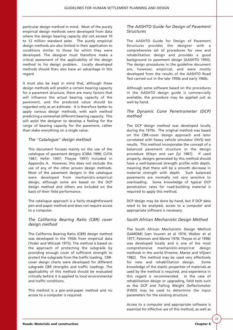
Southern Africa can be divided into three climaticregions:
• a large dry region;• a moderate region; and• a small wet region.
Figure 8.4 is a map of southern Africa, which indicatesthe different climatic regions. These are macroclimatesand it should be kept in mind that differentmicroclimates may occur within these regions. This isparticularly important where such local microclimateshave a high moisture content. This will have a directinfluence on moisture-susceptible materials in basicaccess streets which require specific drainageconsiderations.
Climate and subgrade California BearingRatio (CBR)
The design parameter for the subgrade is the soakedCBR at a representative density. For structural designpurposes, when a material is classified according to theCBR, it is implied that not more than 10% of themeasured values for such a material will fall below theclassification value. A proper preliminary soil surveyshould be conducted.
It is current practice to use soaked CBR values, butusing them in dry regions may be over-conservative(Jordaan 1986). It is suggested that the CBR value of amaterial be increased if the in situ conditions areexpected to be unsoaked, e.g. in dry regions (Haupt1980). An estimate of the CBR at the expected
moisture conditions, i.e. at optimum moisture content(OMC) or, say, 75 per cent of OMC, can be determinedin the laboratory by refraining from soaking thesamples before CBR testing or even drying back to therequired moisture content.
The dynamic cone penetrometer (DCP) can be used todetermine the in-situ CBR and variations in in-situstrengths (Jordaan 1986). The in-situ CBRs determinedwith the DCP can be calibrated by doing laboratory-soaked CBRs. If material parameters such as gradingmodulus (GM), plastic limit (PL) and dry density (DD) areincluded in the analysis, typical relations can be used toderive CBR values (Sampson 1984). The relevantequation is:
loge CBR = 1,1 (logeDCP) + 0,85 (GM) -
0,031 (PL) - 0,001 (DD) + 7,4 (8.9)
where loge is the natural logarithm.
For the material types under consideration, the CBR isdetermined at a 2,54 mm depth of penetration, withDCP penetration in millimetres per blow.
It is current practice for the design parameter forsubgrade to be the soaked California Bearing Ratio(CBR) for paved streets. It is recommended thatunsoaked (field) CBR values should be used particularlyin dry regions (Haupt 1980; Emery 1984 and 1987). Thedynamic cone penetrometer (DCP) is the idealinstrument for such an approach (Kleyn and van Zyl1987; Kleyn 1982). However, it should be pointed out
Climaticregion
Approx.Weinert
Nvalues
< 2
2 - 5
> 5
Wet
Moderate
Dry
NAMIBIA
BOTSWANA
NORTHERN CAPE
WESTERNCAPE
EASTERNCAPE
FREESTATE
NORTHWEST
GA
UTE
NG
NORTHERNPROVINCE
MPUMALANGA
KWAZULUNATAL
Francistown
Walvisbay
Keetmanshoop
Mossel BayPort Elizabeth
East London
Durban
Maputo
Beira
Pietersburg
Jhb
Nelspruit
PietermaritzburgBloemfonteinKimberley
Mmbatho
Gaborone
Cape Town
Windhoek
Bisho
LegendCapitalsJhb = Johannesburg
Figure 8.4: Macro-climatic regions of southern Africa

22
GUIDELINES FOR HUMAN SETTLEMENT PLANNING AND DESIGN
Chapter 8 Roads: Materials and construction
that soaked CBR values may be required for wetregions where no proper drainage can be provided orfor wet-season passability on unpaved streets. Whenthe DCP is used, care should be taken that themoisture content is a fair representation of themoisture content over long periods of time.
The requirement for subgrade or fill CBR is a soakedCBR of at least 3 at 90% Mod AASHTO density in wetareas, and an in-situ CBR of 3 in dry and moderateareas. The material should also have a maximum swellof 1,5% at 100% Mod AASHTO compaction to ensurethat it is not too expansive. If the CBR values aredetermined in the field with the DCP, the subgradeareas with a field CBR of less than 3 will need specialtreatment. If the field CBR values are in excess of 45over a depth of at least 150mm at a density of 95%Mod AASHTO, the subgrade can be considered to besubbase quality, and only a base would be needed.
Material depth
The term “material depth” is used to denote the depthbelow the finished level of the street to which soilcharacteristics have a significant effect on pavementbehaviour. Below this depth, the strength and densityof the soils are assumed to have a negligible effect onthe pavement. The depth approximates the cover for asoil with CBR of 1 - 2. However, in certain special casesthis depth may be insufficient. These cases are listed inthe section dealing with practical considerations(subgrade below material depth).
Table 8.11 specifies the materail depth used fordeterming the design CBR of the subgrade fordifferent street categories.
Delineation of subgrade areas
Any street development should be subdivided intosignificant subgrade areas. However, if the delineationis too fine it could lead to confusion duringconstruction. The preliminary soil survey shoulddelineate subgrade design units on the basis ofgeology, pedology, topography and drainageconditions - or major soil boundaries - on site so thatan appropriate design CBR for each unit can bedefined.
The designer should distinguish between very localisedgood or poor soils and more general subgrade areas.Localised soils should be treated separately from therest of the pavement factors. Normally, localised poorsoils will be removed and replaced by suitable material.
Design CBR of subgrade
For construction purposes the design subgrade CBR islimited to four groups, as shown in Table 8.12.
The CBR is normally determined after samples havebeen soaked for four days. Special measures arenecessary if a material with a CBR of less than 3 isencountered within the material depth. Thesemeasures include stabilisation (chemical ormechanical), modification (chemical), or the removalor addition of extra cover. After the material has beentreated, it will be classified under one of theremaining three subgrade groups.
Design CBR on fill
When the street is on fill, the designer must availhimself of the best information available on thelocal materials that are likely to be used. Thematerial should be controlled to at least thematerial depth. TRH10 (NITRR 1984) should beconsulted when a material with a CBR of less than3 is used in the fill.
Design CBR in cut
The design CBR of the subgrade in a cut should bethe 10 percentile CBR encountered within thematerial depth.
STRUCTURAL DESIGN METHODS
Design methods for paved streets
There are a number of design methods of varyingcomplexity at the disposal of the designer. Some ofthese are purely empirical and others incorporatesome measure of rationality, and were developed bothlocally and abroad.
The designer must always bear the limitations of a
Table 8.11: Material depths to be used fordetermining the design CBRof the subgrades
ROAD CATEGORY MATERIAL DEPTH (mm)
UA 1 000
UB 800
UC 600
UD 400
Table 8.12: Subgrade CBR groups used forstructural design
CLASS SUBGRADE CBR
SG1 >15SG2 7 to 15SG3 3 to 7SG4 <3*
* Special treatment required.
23
GUIDELINES FOR HUMAN SETTLEMENT PLANNING AND DESIGN
Roads: Materials and construction Chapter 8
particular design method in mind. Most of the purelyempirical design methods were developed from datawhere the design bearing capacity did not exceed 10to 12 million standard axles. The purely empiricaldesign methods are also limited in their application toconditions similar to those for which they weredeveloped. The designer must therefore make acritical assessment of the applicability of the designmethod to his design problem. Locally developedmethods should then also have an advantage in thisregard.
It must also be kept in mind that, although thesedesign methods will predict a certain bearing capacityfor a pavement structure, there are many factors thatwill influence the actual bearing capacity of thepavement, and the predicted value should beregarded only as an estimate. It is therefore better toapply various design methods, with each methodpredicting a somewhat different bearing capacity. Thiswill assist the designer to develop a feeling for therange of bearing capacity for the pavement, ratherthan stake everything on a single value.
The “Catalogue” design method
This document focuses mainly on the use of thecatalogue of pavement designs (CSRA 1996; CUTA1987; Hefer 1997; Theyse 1997) included inAppendix A. However, this does not exclude theuse of any of the other proven design methods.Most of the pavement designs in the cataloguewere developed from mechanistic-empiricaldesign, although some are based on the DCPdesign method and others are included on thebasis of their field performance.
The catalogue approach is a fairly straightforwardpen-and-paper method and does not require accessto a computer.
The California Bearing Ratio (CBR) coverdesign method
The California Bearing Ratio (CBR) design methodwas developed in the 1950s from empirical data(Yoder and Witczak 1975). The method is based onthe approach of protecting the subgrade byproviding enough cover of sufficient strength toprotect the subgrade from the traffic loading. CBR-cover design charts were developed for differentsubgrade CBR strengths and traffic loadings. Theapplicability of this method should be evaluatedcritically before it is applied to local environmentaland traffic conditions.
This method is a pen-and-paper method and noaccess to a computer is required.
The AASHTO Guide for Design of PavementStructures
The AASHTO Guide for Design of PavementStructures provides the designer with acomprehensive set of procedures for new andrehabilitation design and provides a goodbackground to pavement design (AASHTO 1993).The design procedures in the guideline documentare, however, empirical, and were mostlydeveloped from the results of the AASHTO RoadTest carried out in the late 1950s and early 1960s.
Although some software based on the proceduresin the AASHTO design guide is commerciallyavailable, the procedure may be applied just aswell by hand.
The Dynamic Cone Penetrometer (DCP)method
The DCP design method was developed locallyduring the 1970s. The original method was basedon the CBR-cover design approach and latercorrelated with heavy vehicle simulator (HVS) testresults. This method incorporates the concept of abalanced pavement structure in the designprocedure (Kleyn and van Zyl 1987). If usedproperly, designs generated by this method shouldhave a well-balanced strength profile with depth,meaning that there will be a smooth decrease inmaterial strength with depth. Such balancedpavements are normally not very sensitive tooverloading. Some knowledge of typical DCPpenetration rates for road-building material isrequired to apply this method.
DCP design may be done by hand, but if DCP dataneed to be analysed, access to a computer andappropriate software is necessary.
South African Mechanistic Design Method
The South African Mechanistic Design Method(SAMDM) (van Vuuren et al 1974; Walker et al1977; Paterson and Maree 1978; Theyse et al 1996)was developed locally and is one of the mostcomprehensive mechanistic-empirical designmethods in the world (Freeme, Maree and Viljoen1982). This method may be used very effectivelyfor new and rehabilitation design. Someknowledge of the elastic properties of materials asused by the method is required, and experience inthis regard is recommended. In the case ofrehabilitation design or upgrading, field tests suchas the DCP and Falling Weight Deflectometer(FWD) may be used to determine the inputparameters for the existing structure.
Access to a computer and appropriate software isessential for effective use of this method, as well as
24
GUIDELINES FOR HUMAN SETTLEMENT PLANNING AND DESIGN
Chapter 8 Roads: Materials and construction
for analysing DCP and FWD data.
Design methods for unpaved streets
Unlike sealed roads, where the application of abituminous surfacing results in a semi-permanentstructure (for up to 20 years) in which deformation orfailure is costly to repair and usually politicallyunacceptable, unsealed roads are far more forgiving.Routine maintenance is essential and localisedproblems are rectified relatively easily. For this reason,the design process for unsealed roads has neverprogressed to the sophisticated techniques developedfor sealed roads.
The main principles in designing unsealed roads are
• to prevent excessive subgrade strain; and
• to provide an all-weather, dust-free surface withacceptable riding quality.
These two requirements are achieved by providing anadequate thickness of suitable material, constructed toa suitable quality. A simple design technique coveringthickness and materials has been developed for SouthAfrica and is summarised in TRH14 Guidelines for roadconstruction materials (NITRR 1984c).
PRACTICAL CONSIDERATIONS
Surface drainage
Experience has shown that inadequate drainage isprobably responsible for more pavement distress insouthern Africa than inadequate structural or materialdesign. Effective drainage is essential for goodpavement performance, and it is assumed in thestructural design procedure.
Drainage for basic access streets
Effective drainage is a prerequisite in the structuraldesign of basic access streets. Drainage design isintegral in stormwater management. As outlined inthe principles of stormwater management, thedesign should allow for non-structural andstructural measures to cope with minor and majorstorms. The non-structural measures are related tooptimising the street layout and the topography toretard stormwater flow and curb the possibleassociated damage. Structural measures includenot only the provision of culverts, pipes orchannels, but also the street itself. With minorstorms, structural measures should ensure thatwater is shed from the street into side drainagechannels, and with major storms, these measuresshould limit the period of impassability while thestreet functions as a drainage channel itself. In thelatter case the street should be paved.
In addition to paving basic access streets forreasons of drainage, erosion control and wet-weather accessibility, other factors such as dust andsocial issues may play a role.
Included in the social issues are politics, adjacentschools and hospitals, and the use of the streets aspublic areas.
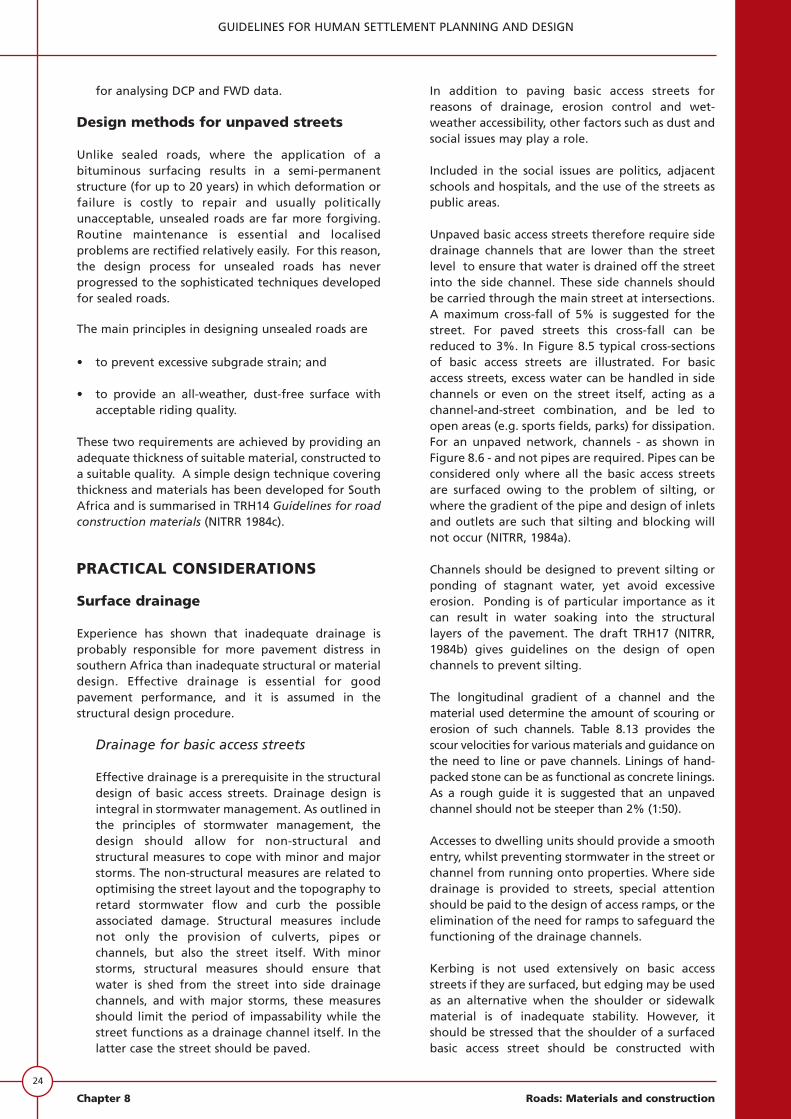
Unpaved basic access streets therefore require sidedrainage channels that are lower than the streetlevel to ensure that water is drained off the streetinto the side channel. These side channels shouldbe carried through the main street at intersections.A maximum cross-fall of 5% is suggested for thestreet. For paved streets this cross-fall can bereduced to 3%. In Figure 8.5 typical cross-sectionsof basic access streets are illustrated. For basicaccess streets, excess water can be handled in sidechannels or even on the street itself, acting as achannel-and-street combination, and be led toopen areas (e.g. sports fields, parks) for dissipation.For an unpaved network, channels - as shown inFigure 8.6 - and not pipes are required. Pipes can beconsidered only where all the basic access streetsare surfaced owing to the problem of silting, orwhere the gradient of the pipe and design of inletsand outlets are such that silting and blocking willnot occur (NITRR, 1984a).
Channels should be designed to prevent silting orponding of stagnant water, yet avoid excessiveerosion. Ponding is of particular importance as itcan result in water soaking into the structurallayers of the pavement. The draft TRH17 (NITRR,1984b) gives guidelines on the design of openchannels to prevent silting.
The longitudinal gradient of a channel and thematerial used determine the amount of scouring orerosion of such channels. Table 8.13 provides thescour velocities for various materials and guidance onthe need to line or pave channels. Linings of hand-packed stone can be as functional as concrete linings.As a rough guide it is suggested that an unpavedchannel should not be steeper than 2% (1:50).
Accesses to dwelling units should provide a smoothentry, whilst preventing stormwater in the street orchannel from running onto properties. Where sidedrainage is provided to streets, special attentionshould be paid to the design of access ramps, or theelimination of the need for ramps to safeguard thefunctioning of the drainage channels.
Kerbing is not used extensively on basic accessstreets if they are surfaced, but edging may be usedas an alternative when the shoulder or sidewalkmaterial is of inadequate stability. However, itshould be stressed that the shoulder of a surfacedbasic access street should be constructed with
25
GUIDELINES FOR HUMAN SETTLEMENT PLANNING AND DESIGN
Roads: Materials and construction Chapter 8
material of at least the same quality as the subbase(Netterberg and Paige-Green 1988).
The shoulder should preferably be protected with abituminous surfacing. The cost of this can be highhowever, and the decision will have to be based onaffordability.
Erosion control for tertiary ways
Erosion control is considered to be the maincriterion in the design of tertiary ways. Stormwatermust be accommodated by ditches and drains onthe sides of the tertiary ways. In Figure 8.6 typicaldetail is given of such ditches. Detail is also given ofstilling ponds, catchwater drains and check dams.These should be seen as typical examplesillustrating the principles involved. Check dams areused on downhill tertiary ways to dissipate theenergy of the stormwater and to form naturalsteps.
When low points are reached, drifts and disheddrains can be used to give preference to the flow ofwater without major structural requirements.Erosion protection on the approaches must beprovided for. Details of typical drifts and dish drainsare shown in Figures 8.7 and 8.8.
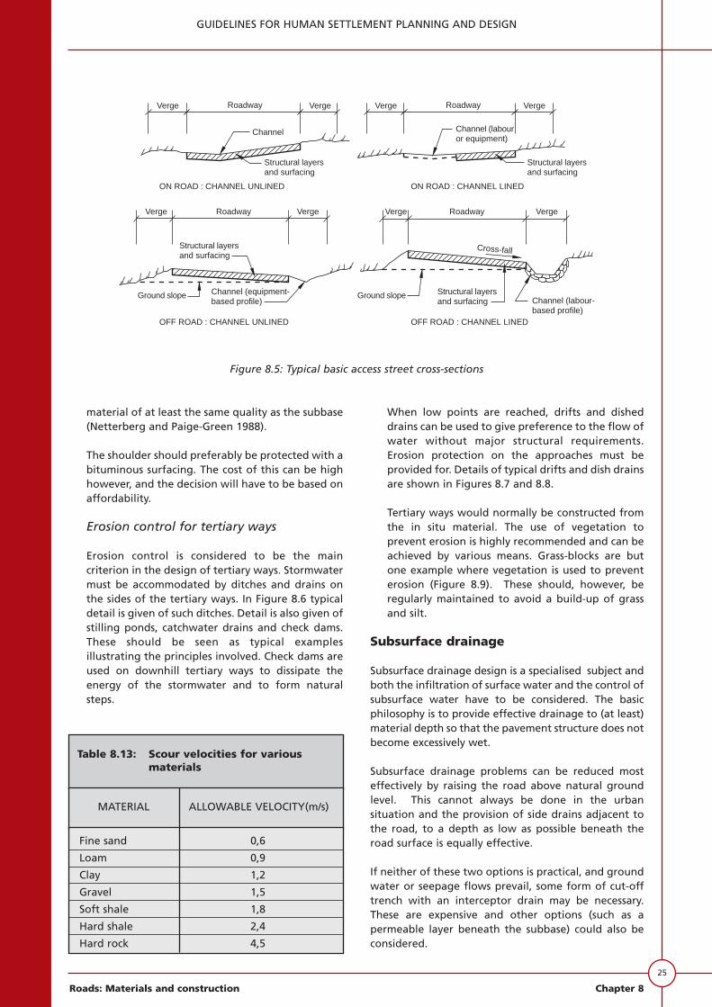
Tertiary ways would normally be constructed fromthe in situ material. The use of vegetation toprevent erosion is highly recommended and can beachieved by various means. Grass-blocks are butone example where vegetation is used to preventerosion (Figure 8.9). These should, however, beregularly maintained to avoid a build-up of grassand silt.
Subsurface drainage
Subsurface drainage design is a specialised subject andboth the infiltration of surface water and the control ofsubsurface water have to be considered. The basicphilosophy is to provide effective drainage to (at least)material depth so that the pavement structure does notbecome excessively wet.
Subsurface drainage problems can be reduced mosteffectively by raising the road above natural groundlevel. This cannot always be done in the urbansituation and the provision of side drains adjacent tothe road, to a depth as low as possible beneath theroad surface is equally effective.
If neither of these two options is practical, and groundwater or seepage flows prevail, some form of cut-offtrench with an interceptor drain may be necessary.These are expensive and other options (such as apermeable layer beneath the subbase) could also beconsidered.
Verge Verge Verge Verge
Verge Roadway Verge Verge Verge
Channel
Roadway
RoadwayRoadway
Structural layersand surfacing
Structural layersand surfacing
and surfacingStructural layers
Structural layersand surfacing Channel (labour-
based profile)
Channel (equipment-based profile)
Ground slope Ground slope
Channel (labouror equipment)
Cross-fall
ON ROAD : CHANNEL UNLINED ON ROAD : CHANNEL LINED
OFF ROAD : CHANNEL UNLINED OFF ROAD : CHANNEL LINED
Figure 8.5: Typical basic access street cross-sections
Table 8.13: Scour velocities for variousmaterials
MATERIAL ALLOWABLE VELOCITY(m/s)
Fine sand 0,6
Loam 0,9
Clay 1,2
Gravel 1,5
Soft shale 1,8
Hard shale 2,4
Hard rock 4,5

26
GUIDELINES FOR HUMAN SETTLEMENT PLANNING AND DESIGN
Chapter 8 Roads: Materials and construction
or village access
0,6m
Dep
thva
ries
0,15m 0,50m 0,75m
0,5m
0,5m
0,50m0,1m 0,1m 0,1m 0,2m0,25m 0,25m
0,05
mCL LC
Normally 4,0m. May beincreased to provide field
Edge of carriageway
Slope
Ditch
Ideally this area tobe left unexcavated.Sometimes a naturalbarrier such as treeor an ant hill can beused to deflect flow
4 m radius
Spacing of mitres
Steep (> 1 in 10)10m c/c
Mild (1 in 20 - 1 in 50)20m c/c
Flat (< 1 in 50)50m c/c Ditch
Slope
Edge of carriageway
Length of mitre:10m gentle slope; 5m steep slope
Outlet
Outlet length of mitrenormally 10m but in veryflat areas a pit may benecessary to effect outfall
IN SLOPING GROUND IN FLAT GROUND
MITRE DRAIN (OR TURN OUT)
A
A
A A
2m ra
dius
2m radius
Interstices filledwith sand/gravel
Brushwoodin fill
Woodeat 100
BRUSHWOOD CHECK DAMSTONE CHECK DAMSECTION B-B
Coarse sand or fine gravelfilter on upstream side
Hand-placed stoneup to 200/300 mm
d 2
Check damprofile
This distance such that gradient (A)
is about 1:70 to 1:100
A
B
A
B
Check dam
Depth of ditch d
Height of check dam 0,5 to 0,7 d
Slope of ditch
0,25
mno
rmal
ly
Cemented m0,15 m thick
LINED DITCH
1
1
11
DETAIL OF
CATCHWATER DRAIN
CATCHWATER DRAIN
Ditch
Carriageway
Berm(if required)
Normally not less than 5,0m
Catchwater drain toculvert or other outlet
Existing ground slope
LONG SECTION OF DITCH
SECTION A-A
Fig. 8.6
/
Spoil on lowerhill side
or village access
0,6m
Dep
thva
ries
0,15m 0,50m 0,75m
0,5m
0,5m
0,50m0,1m 0,1m 0,1m 0,2m0,25m 0,25m
0,05
m
CL LC
Normally 4,0m. May beincreased to provide field
Edge of carriageway
Slope
Ditch
Ideally this area tobe left unexcavated.Sometimes a naturalbarrier such as treeor an ant hill can beused to deflect flow
4 m radius
Spacing of mitres
Steep (> 1 in 10)10m c/c
Mild (1 in 20 - 1 in 50)20m c/c
Flat (< 1 in 50)50m c/c Ditch
Slope
Edge of carriageway
Length of mitre:10m gentle slope; 5m steep slope
Outlet
Outlet length of mitrenormally 10m but in veryflat areas a pit may benecessary to effect outfall
IN SLOPING GROUND IN FLAT GROUND
MITRE DRAIN (OR TURN OUT)
A
A
A A
2m ra
dius
2m radius
Interstices filledwith sand/gravel
Brushwoodin fill
Wooden stakesat 100 mm c/c
BRUSHWOOD CHECK DAMSTONE CHECK DAMSECTION B-B
Coarse sand or fine gravelfilter on upstream side
Hand-placed stoneup to 200/300 mm
CHECK DAMS
d 2
Check damprofile
Note: Check dams to be usedwhere soil is erodible
This distance such that gradient (A)
is about 1:70 to 1:100
A
B
A
B
Check dam
Depth of ditch d
Height of check dam 0,5 to 0,7 d
Slope of ditch
0,25
mno
rmal
ly
Cemented masonry0,15 m thick
LINED DITCH
1
1
11
DETAIL OF
CATCHWATER DRAIN
CATCHWATER DRAIN
Ditch
Carriageway
Berm(if required)
Normally not less than 5,0m
Catchwater drain toculvert or other outlet
Existing ground slope
LONG SECTION OF DITCH
SECTION A-A
/
Spoil on lowerhill side
Figure 8.6: Tertiary ways: ditches and drains

27
GUIDELINES FOR HUMAN SETTLEMENT PLANNING AND DESIGN
Roads: Materials and construction Chapter 8
300m
m20
0mm
3,5 m
1,0m
m
1,5m
2,5m0,5m 0,5m
1,0m
0,5m
0,25
m
Thr
esho
ld w
idth
= 3
,9 m
4,5m
Nor
mal
wid
th o
f roa
d =
5,0
0 m
3,5m
Abs
olut
e m
in. 2
,9m
Notes on slab construction
Aternative 1 (as illustrated insections A-A & B-B)
300 mm compacted gravel overlainwith 200 mm 1:2:4 concrete
Alternative 2 (as illustrated below)
To be used with the objective ofsaving cement.
300 mm compacted gravel overlainwith cement-pitched masonry
Cement mortar brushed in
450 mm nominal size stonelaid on wet concrete
Compacted gravel
Compacted fillBed : 500 mm 1:3:6
concrete
CONSTRUCTION ALTERNATIVE 2
200 mm 1:2:4concrete 300 mm gravel
Masonrytoe wall
Fill to be wellcompacted
Masonryheel wall
SECTION B-B
2%
Marker posts to bemaximum 5,0m centres
Dish = 0,1m
CL
300 mm gravel
Masonryend wall
0,5mToe wall
1 in 101 in 10
300 mm square x 250 mm highwhite painted masonrymarker postsNormal road
level
200 mm 1:2:4 concreteto have rough finishtransverse to road Capplied by brush orby tamping board
SECTION A-A
to be at least bed widthWidth L as directed but
L
2Ditch entry Ditch entry
stream flowB
CL
Taper over 1,5m
Ditch entry Ditch entryB
L (varies - min. 4,0 m)2L (varies)1 L1
PLAN
Apron of large pitched stonesor, if necessary, gabions on marker post
Peg distance painted
Apron
Masonryfoundationwalls : toe,heel & end
Mortar to be 1 partcement to 6 partssand
deep
A A
Figure 8.7: Tertiary ways: drift

28
GUIDELINES FOR HUMAN SETTLEMENT PLANNING AND DESIGN
Chapter 8 Roads: Materials and construction
Dished10%10%
Cement pitchedmasonry
Cut off wall
SECTION C-C
PLAN
DISH DRAIN TYPE 1
DETAIL
Any surplus stoneto be used as apron as bottom of ditch
Level at X to be the sameFlow
X X
Ditch
slope
Slope
ditch
Carriageway
to suitArea shaped 1,5%
Dish drain may needextending to effectsuitable outfall
SECTION A-A
Normal road level
Cement pitmasonry
Dry pitchedmasonry
Cut off
Cut off wallFlow
Area shapedto suit
Outfall
Dry pitched masonryapron as required
1,5%
Dish drain to beextended as required
CONSTRUCTION
As for dish drain type 1
WHERE TO USE DISH DRAITYPE 2
Where anticipated flows arelight to moderate but wherethe use of a culvert isunnecessary or impractical
Surface tobe smooth
CONSTRUCTION
Bed: 50 mm 1:3:6 concreteStone: 150 mm nominal size well bedded
in concreteSurface: cement mortar brushed in
WHERE TO USE DISH DRAIN TYPE 1
Gently sloping ground. Very lowflows anticipated
Cut off wall maybe required atinlet depth 0,5 m
10% on C10 % on CL L
Dished
10%
(on C )L L(on C )
10%
LC
X X
A A
B B
C
C
PLAN
To outfall
wall
3,0m 3,0m 3,0m 3,0m 3,0m
0,50m
0,30
m
0,15
0,05
0,2m
3,0m 2,0m 3,0m
Fig. 8.8
Figure 8.8: Tertiary ways: dish drains
Subsurface water problems are frequentlyencountered where water provision in urban areas isby way of standpipes adjacent to roads. Apart fromthe surface runoff, significant seepage into the groundoccurs and this frequently passes directly beneath theadjacent road. Careful drainage in the areassurrounding standpipes is thus essential.
As discussed earlier, subsurface drainage is aspecialised field requiring a good knowledge of waterflow regimes, drainage paths and filter criteria, andspecialist assistance should be obtained.
Compaction
The design procedures assume that the specifiedmaterial properties are satisfied in the field. A numberof the traditional material properties (e.g. grading,plasticity) are independent of the construction process,but the strength is strongly dependent on thecompaction achieved in the field. The design strengthis based on the laboratory-determined strength of thematerial at a specified density. In order to ensure thatthis strength is obtained in the field, that particulardensity must be achieved during the field compaction.Table 8.14 gives the minimum compaction standardsrequired for the various layers of the pavementstructure. Note that, below base level, the standardsare independent of the type of material used. As most
29
GUIDELINES FOR HUMAN SETTLEMENT PLANNING AND DESIGN
Roads: Materials and construction Chapter 8
500 x 500
Original groundcut to sectionshown
Plant grass andshrubs here
Stepped embankment(note vertical walls)
Drainage channel
Way
Slope into drainRootsystem
Shrub planting
Six holes forsoil and grass
Ribs reinforcedwith wire
Reinforcement
Grass
Roots
May be fitted tointerlock withadjacent units
SECTIONAL DETAIL
PLAN
SECTION A-A
A A
Rootsystem
Figure 8.9: Typical grass block and vegetation

30
GUIDELINES FOR HUMAN SETTLEMENT PLANNING AND DESIGN
Chapter 8 Roads: Materials and construction
materials below base level will have a potential densitysomewhat in excess of the specified density which isrelatively easily achieved if compaction is carried out atthe correct moisture content, an attempt should bemade to get as close to 100% Mod AASHTO density aspossible. This has significant benefits in terms of anincreased shear strength, a reduced potential to rut,and lower moisture susceptibility. Standard practiceshould be to roll the layer to refusal density based onproof rolling of a short section prior to its fullcompaction. Hand-held rollers may be inadequate toachieve the required density.
Subgrade below material depth
Special subgrade problems requiring specialisttreatment may be encountered. The design procedureassumes that these have been taken into accountseparately. The main problems that have to beconsidered are the following:
• the extreme changes in volume that occur in somesoils as a result of moisture changes (e.g. inexpansive soils and soils with collapsible structures);
• other water-sensitive soils (dispersive or erodiblesoils);
• flaws in structural support (e.g. sinkholes, miningsubsidence and slope instability;
• the non-uniform support that results from widevariations in soil types or states;
• the presence of soluble salts which, underfavourable conditions, may migrate upwards andcause cracking, blistering or loss of bond of thesurfacing, disintegration of cemented bases andloss of density of untreated bases; and
• the excessive deflection and rebound of highlyresilient soils during and after the passage of a load(e.g. in ash, micaceous and diatomaceous soils).
The techniques available for terrain evaluation andsoil mapping are given in TRH2 Geotechnical and soilengineering mapping for roads and the storage ofmaterials data (NITRR 1978). Specialist advice shouldbe obtained where necessary for specific problemareas. The design of embankments should be done inaccordance with TRH10 Site investigation and thedesign of road embankments (NITRR 1984d).
Street levels
The fact that the provision of vehicular accessadjoining streets, dwellings and commercialestablishments is the primary function of an urbanstreet means that street levels become a rather moreimportant factor in urban areas than they are in ruralor inter-urban street design. Urban street levels placesome restrictions on rehabilitation and create specialmoisture/drainage conditions.
Surfacing Asphalt 95% 75-blow Marshall
Base (upper and lower) Crushed stone G1 86% to 88% apparent densityG2 100% to 102% mod AASHTO
Crushed stone G3 98% mod AASHTOand gravel G4
Asphalt 95% 75-blow Marshall92% theoretical max
Cemented 97% mod AASHTO
Subbase (upper and lower) 95% mod AASHTO
Selected subgrade 93% mod AASHTO
Subgrade (within 200 mm of selected subgrade) 90% mod AASHTO(within material depth) 85% mod AASHTO
Fill (cohesionless sand) 90% mod AASHTO(100% mod AASHTO)
Table 8.14: Compaction requirements for the construction of pavement layers (andreinstatement of pavement layers)
PAVEMENT LAYER COMPACTED DENSITY
In some cases, rehabilitation in the form of an overlaymay cause a problem, particularly with respect to thelevel of kerbs and channels, camber and overheadclearances. In these cases strong consideration shouldbe given to bottom-heavy designs (i.e. designs with acemented subbase and possibly a cemented base),which would mainly require the same maintenance asthin surfacings and little structural maintenanceduring the analysis period.
Urban streets are frequently used as drainage channelsfor surface-water runoff. This is in sharp contrast withurban, inter-urban and rural roads which are usuallyraised to shed the water to side table drains somedistance from the road shoulder.
Service trenches
Trenches excavated in the pavement to provideessential services (electricity, water, telephone, etc) arefrequently a source of weakness. This is a result ofeither inadequate compaction during reinstatement,or saturation of the backfill material.
Compaction must achieve at least the minimumdensities specified in the catalogue of designs andmaterial standards (Table 8.14). These densities arereadily achieved when granular materials are used, butit becomes much more difficult when natural materialsare used, particularly in the case of excavated clays.When dealing with clay subgrades it is recommendedthat, if it is economically feasible, a moderate-qualitygranular material be used as a trench backfill inpreference to the excavated clay. In streets of CategoryUB and higher it is preferable to stabilise all thebackfill material and in lower categories the provisionof a stabilised “cap” over the backfill may beconsidered to eliminate settlement as far as possible.Care must be taken not to over-stabilise (i.e. produce aconcrete) as this results in significant problems with
adhesion of the surfacing and differential deflectionscausing failure around the particles.
Service trenches can also be the focal points ofdrainage problems. Settlement in the trench, givingrise to standing water and possibly to cracking of thesurface, will permit the ingress of moisture into thepavement. Fractured water, sewerage or stormwaterpipes lead to saturation in the subgrade and possiblyin the pavement layers as well.
Alternatively, a trench backfilled with granularmaterial may even act as a subsurface drain, but thenprovision for discharge must be made. It is, however,generally recommended that the permeability of thebackfill material should be as close as possible to thatof the existing layers in order to retain a uniformmoisture flow regime within the pavement structure.
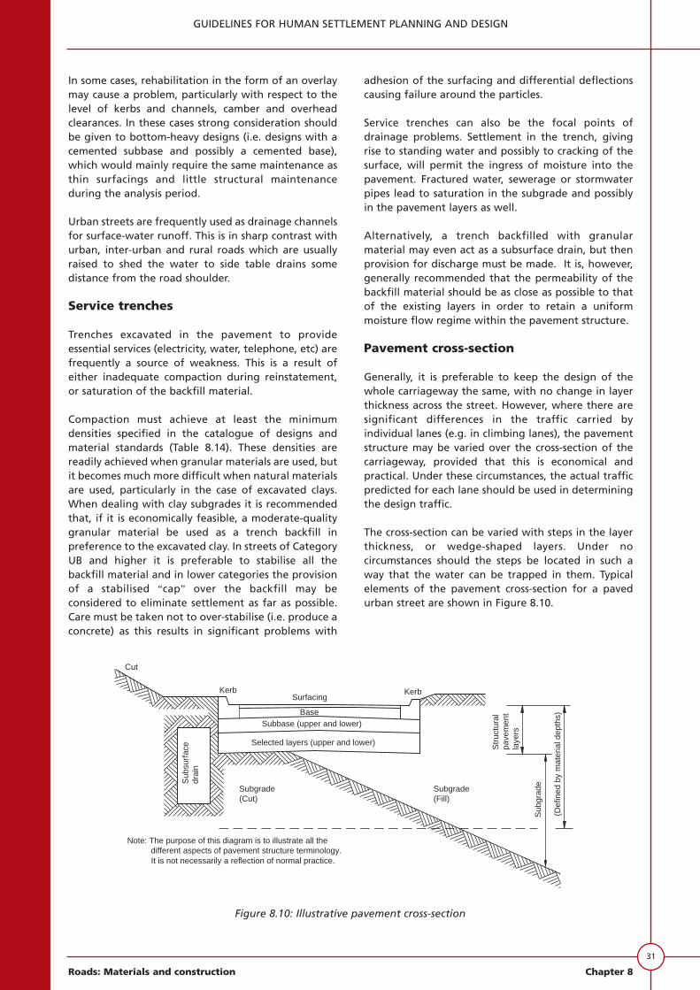
Pavement cross-section
Generally, it is preferable to keep the design of thewhole carriageway the same, with no change in layerthickness across the street. However, where there aresignificant differences in the traffic carried byindividual lanes (e.g. in climbing lanes), the pavementstructure may be varied over the cross-section of thecarriageway, provided that this is economical andpractical. Under these circumstances, the actual trafficpredicted for each lane should be used in determiningthe design traffic.
The cross-section can be varied with steps in the layerthickness, or wedge-shaped layers. Under nocircumstances should the steps be located in such away that the water can be trapped in them. Typicalelements of the pavement cross-section for a pavedurban street are shown in Figure 8.10.
31
GUIDELINES FOR HUMAN SETTLEMENT PLANNING AND DESIGN
Roads: Materials and construction Chapter 8
Figure 8.10: Illustrative pavement cross-section
Cut
KerbSurfacing
BaseSubbase (upper and lower)
Selected layers (upper and lower)
Kerb
Subgrade(Cut)
Sub
surf
ace
drai
n
Str
uctu
ral
pave
men
tla
yers
Sub
grad
e
(Def
ined
by
mat
eria
l dep
ths)
Subgrade(Fill)
Note: The purpose of this diagram is to illustrate all thedifferent aspects of pavement structure terminology.It is not necessarily a reflection of normal practice.
32
GUIDELINES FOR HUMAN SETTLEMENT PLANNING AND DESIGN
Chapter 8 Roads: Materials and construction
Considerations for concrete pavements
Details on the design of concrete pavements arebeyond the scope of this document. However, somebasic practical recommendations are offered below(SA Department of Transport 1977):
• The subgrade should be prepared to provide auniform support.
• The subbase should be stabilised to a high qualityto provide a non-pumping, erosion-resistant,homogeneous pavement support.
• When jointed concrete pavements are used,attention should be given to joint details such asspacing, type and sealing.
Kerbs and channels
Kerbs and channels are important to prevent edgeerosion and to confine stormwater to the streetsurface.
Consideration should be given to the type and methodof construction of kerbs when deciding on a layerthicknes for the base.
It is common practice to construct kerbs upon the(upper) subbase layer to provide edge restraint for agranular base. This restraint will help to provide thespecified density and strength. Care must be taken toensure that this type of structure does not “box”moisture into the base course material.
In the case of kerbing with a fixed size (i.e. precastkerbing or kerbing with fixed shutters cast in situ) itmay be advantageous to design the base thickness toconform with the kerb size (e.g. if the design calls fora 30 mm AG with a 125 mm G4 underlay, and thegutter face is 160mm, rather use a 130 mm G4).
Edging
Instead of kerbs, edging could be used for low-trafficstreets when the shoulder or sidewalk material is ofadequate stability. This material should be shaped tothe correct level and the edge may be sealed with aprime coat, a sand seal, a slurry seal or a premix. Adegree of saving may be possible by utilising trimmedgrass verges where longitudinal gradients are low andstormwater flows are not likely to be high.
Accessibility
Access to dwelling units should be provided for in sucha way that adequate sight distances and a smoothentry are provided, but the access ways should at thesame time keep stormwater on the street fromrunning into adjacent properties.
At pedestrian crossings special sloped openings in thekerbs should be provided to accommodate thehandicapped and hand-pushed carts.
COST ANALYSIS
General
Alternative pavement designs should be compared onthe basis of cost. The cost analysis should be regardedas an aid to decision-making. However, a cost analysismay not take all the necessary factors into account andit should therefore not override all otherconsiderations. The main economic factors thatdetermine the cost of a facility are the analysis period,the structural design period, the construction cost, themaintenance cost, the salvage value at the end of theanalysis period and the real discount rate.
A complete cost analysis should be done for CategoryUA and UB streets. For Category UC and UD streets, acomparison of the construction and maintenance costswill normally suffice.
The method of cost analysis put forward in thisdocument should be used only to compare pavementstructures in the same street category. This is becausestreets in different street categories are constructed todifferent standards and are expected to performdifferently, with different terminal levels of service.The effect these differences have on street user costs isnot taken into account directly.
The choice of analysis period and structural designperiod will influence the cost of a street. The finaldecision will not necessarily be based purely oneconomics, but will depend on the design strategy.
The construction cost should be estimated fromcurrent contract rates for similar projects.Maintenance costs should include the cost ofmaintaining adequate surfacing integrity (e.g.through resealing) and the cost of structuralmaintenance (e.g. the cost of an asphalt overlay). Thesalvage value of the pavement at the end of theanalysis period can contribute to the next pavement.However, geometric factors such as minorimprovements to the vertical and horizontalalignment and the possible relocation of drainagefacilities make the estimation of the salvage value verydifficult.
Present worth
The total cost of a project over its life is theconstruction cost plus maintenance costs, minus thesalvage value. The total cost can be expressed in anumber of different ways but, for the purpose of thisdocument, the present worth of costs (PWOC)approach has been adopted.

The present worth of costs can be calculated asfollows:
PWOC = C + M1 (1 + r)-xj + ...Mj(1 + r)-xj + ... -S(1 + r)-z
(8.10)
where
PWOC = present worth of cost
C = present cost of initial construction
Mj = cost of the jth maintenance measure expressed in terms of current costs
r = real discount rate
xj = number of years from the present to the jth
maintenance measure, within the analysis period
z = analysis period
S = salvage value of pavement at the end of the analysis period, expressed in terms of the present value.
Construction costs
The checklist of unit costs should be used to calculatethe equivalent construction cost per square metre.Factors to be considered include the availability ofnatural or local commercial materials, their expectedcost trends, the conservation of aggregates in certainareas, and practical aspects such as speed ofconstruction and the need to foster the developmentof alternative pavement technologies. The potentialfor labour-based construction also needs to beconsidered.
The cost of excavation should be included as certainpavement types will involve more excavation thanothers.
Maintenance costs
There is a relation between the type of pavement andthe maintenance that might be required in the future.When different pavement types are compared on thebasis of cost, these future maintenance costs should beincluded in the analysis to ensure that a soundcomparison is made. It should also be noted thatrelaxations of material, drainage or pavementthickness standards will normally result in increasedmaintenance costs.
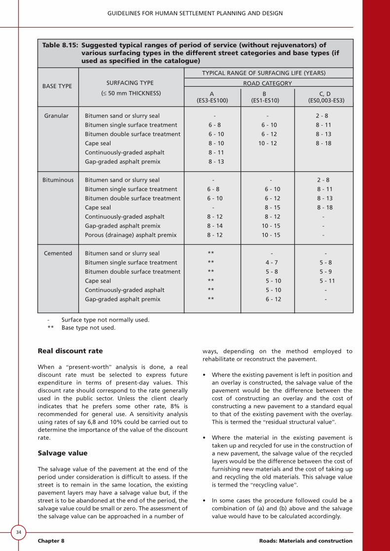
Figures 8.2 and 8.3 show that the life of the surfacingand water ingress into the pavement play animportant part in the behaviour of some pavements.For this reason, planned maintenance of the surfacingis very important to ensure that these pavements
perform satisfactorily. The service life of each type ofsurfacing will depend on the traffic and the type ofbase used. Table 8.15 gives guidelines regarding theservice life that can be expected from various surfacingtypes. These values may be used for a more detailedanalysis of future maintenance costs.
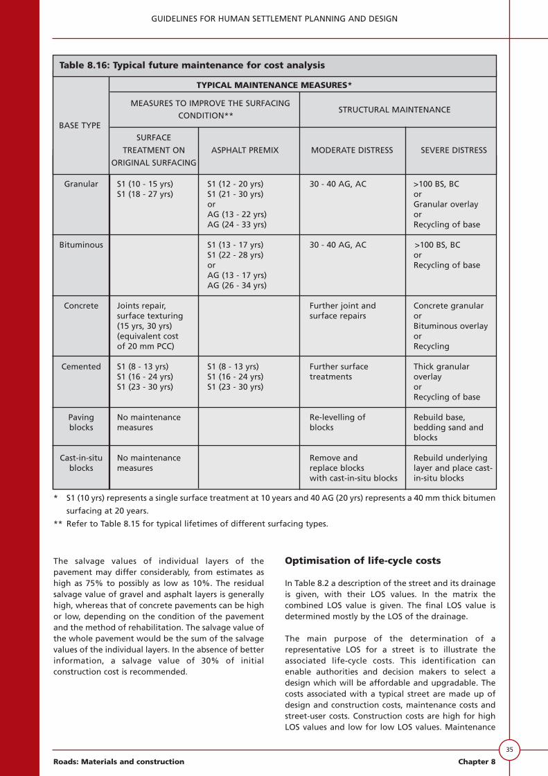
Typical maintenance measures that can be used for thepurpose of cost analysis are given in Table 8.16. Itshould be noted that, since the costs are discounted tothe present worth, the precise selection of themaintenance measure is not very important. Somemaintenance measures are used more commonly onspecific pavement types and this is reflected in Table8.16. There are two types of maintenance:
• measures to improve the condition of thesurfacing; and
• structural maintenance measures applied at theend of the structural design period.
The structural design period (SDP) has been defined asthe period for which it is predicted with a high degreeof confidence that no structural maintenance will berequired. Therefore, typical structural maintenancewill generally only be necessary at a later stage. Ifstructural maintenance is done soon after the end ofthe structural design period, the distress encounteredwill only be moderate. When structural maintenance isdone much later, the distress will generally be moresevere. Figure 8.11 indicates the degree of distress tobe expected at the time of rehabilitation for differentstructural design periods. Table 8.16 makes provisionfor both moderate and severe distress.
The typical maintenance measures given in Table 8.16should be replaced by more accurate values, if specificknowledge about typical local conditions is available.
Street-user delay costs should also be considered,although no proper guide for their determination isreadily available. The factors that determine overallstreet user costs are:
• running costs (fuel, tyres, vehicle maintenance anddepreciation), which are largely related to thestreet alignment, but also to the riding quality(PSI);
• accident costs, which are related to streetalignment, skid resistance and riding quality; and
• delay costs, which are related to the maintenancemeasures applied and the traffic situation on thestreets. This is a difficult factor to assess as it mayinclude aspects such as the provision of detours.
33
GUIDELINES FOR HUMAN SETTLEMENT PLANNING AND DESIGN
Roads: Materials and construction Chapter 8
Real discount rate
When a “present-worth” analysis is done, a realdiscount rate must be selected to express futureexpenditure in terms of present-day values. Thisdiscount rate should correspond to the rate generallyused in the public sector. Unless the client clearlyindicates that he prefers some other rate, 8% isrecommended for general use. A sensitivity analysisusing rates of say 6,8 and 10% could be carried out todetermine the importance of the value of the discountrate.
Salvage value
The salvage value of the pavement at the end of theperiod under consideration is difficult to assess. If thestreet is to remain in the same location, the existingpavement layers may have a salvage value but, if thestreet is to be abandoned at the end of the period, thesalvage value could be small or zero. The assessment ofthe salvage value can be approached in a number of
ways, depending on the method employed torehabilitate or reconstruct the pavement.
• Where the existing pavement is left in position andan overlay is constructed, the salvage value of thepavement would be the difference between thecost of constructing an overlay and the cost ofconstructing a new pavement to a standard equalto that of the existing pavement with the overlay.This is termed the “residual structural value”.
• Where the material in the existing pavement istaken up and recycled for use in the construction ofa new pavement, the salvage value of the recycledlayers would be the difference between the cost offurnishing new materials and the cost of taking upand recycling the old materials. This salvage valueis termed the “recycling value”.
• In some cases the procedure followed could be acombination of (a) and (b) above and the salvagevalue would have to be calculated accordingly.
34
GUIDELINES FOR HUMAN SETTLEMENT PLANNING AND DESIGN
Chapter 8 Roads: Materials and construction
Table 8.15: Suggested typical ranges of period of service (without rejuvenators) ofvarious surfacing types in the different street categories and base types (ifused as specified in the catalogue)
Granular
Bituminous
Cemented
Bitumen sand or slurry seal - - 2 - 8
Bitumen single surface treatment 6 - 8 6 - 10 8 - 11
Bitumen double surface treatment 6 - 10 6 - 12 8 - 13
Cape seal 8 - 10 10 - 12 8 - 18
Continuously-graded asphalt 8 - 11
Gap-graded asphalt premix 8 - 13
Bitumen sand or slurry seal - - 2 - 8
Bitumen single surface treatment 6 - 8 6 - 10 8 - 11
Bitumen double surface treatment 6 - 10 6 - 12 8 - 13
Cape seal - 8 - 15 8 - 18
Continuously-graded asphalt 8 - 12 8 - 12 -
Gap-graded asphalt premix 8 - 14 10 - 15 -
Porous (drainage) asphalt premix 8 - 12 10 - 15 -
Bitumen sand or slurry seal ** - -
Bitumen single surface treatment ** 4 - 7 5 - 8
Bitumen double surface treatment ** 5 - 8 5 - 9
Cape seal ** 5 - 10 5 - 11
Continuously-graded asphalt ** 5 - 10 -
Gap-graded asphalt premix ** 6 - 12 -
BASE TYPE SURFACING TYPE
TYPICAL RANGE OF SURFACING LIFE (YEARS)
(≤ 50 mm THICKNESS)
ROAD CATEGORY
A B C, D(ES3-ES100) (ES1-ES10) (ES0,003-ES3)
- Surface type not normally used.** Base type not used.
The salvage values of individual layers of thepavement may differ considerably, from estimates ashigh as 75% to possibly as low as 10%. The residualsalvage value of gravel and asphalt layers is generallyhigh, whereas that of concrete pavements can be highor low, depending on the condition of the pavementand the method of rehabilitation. The salvage value ofthe whole pavement would be the sum of the salvagevalues of the individual layers. In the absence of betterinformation, a salvage value of 30% of initialconstruction cost is recommended.
Optimisation of life-cycle costs
In Table 8.2 a description of the street and its drainageis given, with their LOS values. In the matrix thecombined LOS value is given. The final LOS value isdetermined mostly by the LOS of the drainage.
The main purpose of the determination of arepresentative LOS for a street is to illustrate theassociated life-cycle costs. This identification canenable authorities and decision makers to select adesign which will be affordable and upgradable. Thecosts associated with a typical street are made up ofdesign and construction costs, maintenance costs andstreet-user costs. Construction costs are high for highLOS values and low for low LOS values. Maintenance
35
GUIDELINES FOR HUMAN SETTLEMENT PLANNING AND DESIGN
Roads: Materials and construction Chapter 8
S1 (10 - 15 yrs) S1 (12 - 20 yrs) 30 - 40 AG, AC >100 BS, BCS1 (18 - 27 yrs) S1 (21 - 30 yrs) or
or Granular overlayAG (13 - 22 yrs) orAG (24 - 33 yrs) Recycling of base
S1 (13 - 17 yrs) 30 - 40 AG, AC >100 BS, BCS1 (22 - 28 yrs) oror Recycling of baseAG (13 - 17 yrs)AG (26 - 34 yrs)
Joints repair, Further joint and Concrete granularsurface texturing surface repairs or(15 yrs, 30 yrs) Bituminous overlay(equivalent cost orof 20 mm PCC) Recycling
S1 (8 - 13 yrs) S1 (8 - 13 yrs) Further surface Thick granularS1 (16 - 24 yrs) S1 (16 - 24 yrs) treatments overlayS1 (23 - 30 yrs) S1 (23 - 30 yrs) or
Recycling of base
No maintenance Re-levelling of Rebuild base,measures blocks bedding sand and
blocks
No maintenance Remove and Rebuild underlyingmeasures replace blocks layer and place cast-
with cast-in-situ blocks in-situ blocks
Granular
Bituminous
Concrete
Cemented
Pavingblocks
Cast-in-situblocks
* S1 (10 yrs) represents a single surface treatment at 10 years and 40 AG (20 yrs) represents a 40 mm thick bitumen
surfacing at 20 years.
** Refer to Table 8.15 for typical lifetimes of different surfacing types.
TYPICAL MAINTENANCE MEASURES*
BASE TYPE
MEASURES TO IMPROVE THE SURFACINGSTRUCTURAL MAINTENANCE
CONDITION**
SURFACE
TREATMENT ON ASPHALT PREMIX MODERATE DISTRESS SEVERE DISTRESS
ORIGINAL SURFACING
Table 8.16: Typical future maintenance for cost analysis

36
GUIDELINES FOR HUMAN SETTLEMENT PLANNING AND DESIGN
Chapter 8 Roads: Materials and construction
costs, on the contrary, are low for high LOS values andhigh for low LOS values.
This concept is illustrated in Figure 8.12 with typical,present worth-of-cost versus LOS values. The combinedcost curve has a typical minimum value between thehighest and lowest LOS values. Street-user costs arelow for high LOS streets and high for low LOS streets.
Figure 8.11: Degree of structural distress to beexpected at the time of rehabilitation for different
structural design periods
Figure 8.12: Typical cost versus level of service curvevalues
DISCUSSION ON THE DESIGNPROCEDURES FOR DIFFERENT STREETTYPES
At this stage the designer should have gatheredenough information on the street(s) to be designed, tobe able to decide which design procedure to follow -as illustrated in Figure 8.1. If an existing network is tobe upgraded, the information contained in the streetprofiles may be used to determine paving priorities atthis stage. With a background knowledge of the basicconcepts from the previous section, it is now possibleto go into the detailed structural design of the streetpavements.
PAVED ARTERIAL AND ACCESSSTREETS
The design process
The portion of the flow diagram in Figure 8.1 thatrefers to the design of paved arterial and access routesis enlarged upon in Figure 8.13, and divided into 8sections. Each section will be treated separately but allsections have to be considered as a whole before adesign can be produced.
The first five sections represent the basic inputs topavement design, namely street category, designstrategy, design traffic, material availability andenvironment. The sixth section explains how, with theseas inputs, the designer can then use an appropriatedesign method to obtain possible pavement structures.Information on certain practical considerations in thedesign of streets follows in the seventh section. In thefinal section the analysis of alternative designs on a life-cycle cost basis, in the light of construction costs andmaintenance costs, is considered.
A simplified flow diagram for the structural design ofresidential streets (Category UC and UD only) issuggested in Figure 8.14.
Street category
The street category will have been identifiedduring the process of compiling the street profile,and will most likely be UA, UB or UC. The section oncharacteristics of streets may be consulted for adiscussion on street categories in general.
Design strategy
Select an appropriate analysis and structural designperiod for the street under consideration. Thesection on street standards provides guidelines ontypical analysis and design periods and lists otherfactors that need to be considered.
Total
Maintenance
Construction
5 4 3 2 10
0,25
0,50
0,75
1,00
1,25
1,50
1,75
2,00
2,25
Pre
sent
wor
th o
f cos
ts (
R x
10
)6
Level of service (LOS)WorstBest
0 5 10 15 20 25 30
5
10
15
20
25
30
35
40
Seve
re d
istre
ss
Mod
erat
e di
stre
ss
Limite
d str
uctu
ral d
istre
ss
Tim
e of
reh
abili
tatio
n (y
ears
)
Length of structural design period (years)

Design bearing capacity
Calculate the cumulative equivalent traffic for theparticular street, according to the procedureoutlined in the section on design strategy. Based onthe cumulative equivalent traffic, an appropriatepavement class or design bearing-capacity intervalmay then be selected from Table 8.5.
Materials
Most of the materials for the selected, subbase andbase layers of the pavement structures applicableto arterial and access streets will usually have to beimported. Possible material sources and theavailability and cost of different types of materialshould be established. The availability of materialcombined with the expected behaviour of themajor types of material and pavement, as discussedin the section on materials, will determine the finalselection of the appropriate materials andpavements for particular needs.
Environment
The two most important environmental factors toconsider are the climatic region and the design of
the subgrade on which the street will beconstructed. These are discussed in the section onenvironment.
Structural design
The actual structural design has two aspects - theselection of appropriate pavement types and anappropriate design method for the particularstreet.
Pavement selection
The behaviour of different pavement types hasbeen dealt with. Certain types may not be suitablefor some street categories, traffic classes or climaticregions. A number of alternative types should,however, be selected. The most cost-effectivedesign will then be identified in the economicanalysis.
Pavement structures with thin, rigid or stiff layersat the top (shallow structures) are generally moresensitive to overloading than deep structures. Ifmany overloaded vehicles can be expected, shallowstructures should be avoided.
37
GUIDELINES FOR HUMAN SETTLEMENT PLANNING AND DESIGN
Roads: Materials and construction Chapter 8
Selectroad category
UA, UB, UC, ORUD
design strategySelect
Analysis periodand structuraldesign period
Alternativestrategies
design traffic
EO - E4Traffic classes
Estimate
materials
materials
Unit costs
Availability of
Consider
Unit costsPast experience
Topography
grade areasDelineate sub-
Climatic region
Defineenvironment
Design CBR
Structuraldesign
Pavementbehavior
Terminalcondition
Pavement typeselection
Catalogue
ConsiderationsPracticalInclude
Drainage
Compaction
Problemsubgrades
Cross-section
Concretepavements
Discount rate
Constructioncosts
of costsPrevent worth
AnalysisDo cost
maintenanceFuture
Salvage value
SECTION 1
SECTION 2
SECTION 3
SECTION 4
SECTION 5
SECTION 6
SECTION 7
SECTION 8
*
*
*
*
* Refer back to SECTION 2, reiterate
Figure 8.13: Structural design flow diagram (mainly for category UA and UB streets)

38
GUIDELINES FOR HUMAN SETTLEMENT PLANNING AND DESIGN
Chapter 8 Roads: Materials and construction
Figure 8.3 indicates that the more rigid structuresdeteriorate rapidly once distress sets in, whereasthe more flexible pavements generally deterioratemore slowly. Signs of distress are often more visibleon rigid pavements.
Pavement structures consisting of water-susceptible materials may be undesirable for wetclimatic regions, unless special provision is made fordrainage.
Table 8.17 shows recommended pavement types(base and subbase) for different street categoriesand traffic classes. Reasons why certain pavementtypes are not recommended are also stated briefly.
Possible condition at end of structural designperiod:
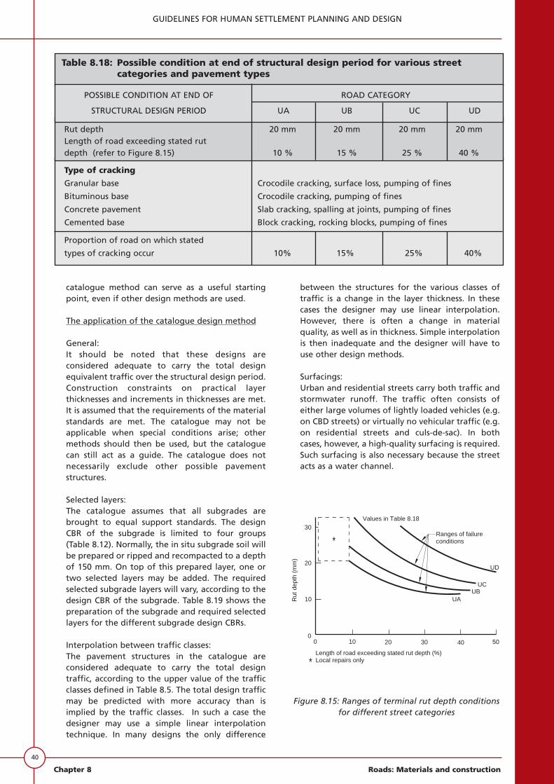
There is no design method available to predict theexact condition of a length of street 10 to 20 yearsin the future. However, certain modes of distresscan be expected in certain pavement types andaccount must be taken of such distress. Table 8.18shows acceptable terminal conditions of rut depthand cracking for the various street categories andpavement types. Figure 8.15 demonstrates that therut depth values in Table 8.18 actually representranges of failure conditions.
Although the net depth conditions may be
classified as terminal, there may be instances wherethe rutting has occurred primarily in the subgradeand the structural layers are still integral. In thesecases the rutting may be rectified - using, forexample, a thick slurry - and the street maycontinue to provide an acceptable level of service.
Design method selection
The designer may use a number of designprocedures, such as the mechanistic designmethod, the AASHTO structural number method,the CBR cover curves or the catalogue of designsgiven in Appendix A. A brief overview of a selectednumber of design methods is given in the sectionon structural design methods above. Whatever thestrategy used, traffic, available materials andenvironment must be taken into account. Someestimation of future maintenance measures isnecessary before a comparison can be made on thebasis of present worth of costs. Special constructionconsiderations that might influence either thepavement structure or the pavement costs arediscussed below in the section dealing withpractical considerations.
This document includes the application of thecatalogue design method, which is given in detailin Appendix A. However, the best results willprobably be obtained if the catalogue is usedtogether with some other design method. The
0.0000
Selectroad category
UA, UB, UC, orUD
design traffic
traffic
Consider
Estimate
materials
materials
Unit costs
Availability of
Consider
Past experience
Topography
grade areasDelineate sub-
Climatic region
Defineenvironment
Design CBR
Structuraldesign
Pavementbehaviour
Pavement typeselection
Catalogue
considerationspracticalInclude
Drainage
Compaction
Problemsub grades
Cross-section
Concretepavements
of constructionPresent worth
analysisDo cost
SECTION 1
SECTION 3
SECTION 4
SECTION 5
SECTION 6
SECTION 7
SECTION 8
construction
costs
Figure 8.14: Simplified design flow diagram for residential streets (category UC and UD)

39
GUIDELINES FOR HUMAN SETTLEMENT PLANNING AND DESIGN
Roads: Materials and construction Chapter 8
GranularGranular Uncertain behaviour
Cemented
Asphalt Granular
hot-mix Cemented
Extra thickness required Granular to prevent fatigue
Concretecracking
Too expensive, too Cemented difficult to trench
Fatigue cracking,
Granular pumping and rocking
Cemented of blocks
CementedShrinkage cracks
unacceptable
GranularNot recommended at
Paving blocksCemented
high speeds
Bituminous Granular
cold-mixCemented
Macadams Granular
Cemented
Cast-in-situ Not recommended at
blocks high speeds
Table 8.17: Suggested pavement types for different road categories and traffic classes
PAVEMENT TYPE STREET CATEGORY AND PAVEMENT CLASS (DESIGN ABBREVIATED REASON WHY
BEARING CAPACITY)* THE LISTED PAVEMENT
TYPES ARE NOT
BASE SUBBASEUA UB UC UD RECOMMENDED FOR
ES ES ES ES ES ES ES ES ES ESTHE GIVEN STREET
CATEGORY 30 10 3 3 1 1 0,3 0,1 0,1 0,03 AND TRAFFIC LOADING
See Table 8.6 for definition of pavement classes.
40
GUIDELINES FOR HUMAN SETTLEMENT PLANNING AND DESIGN
Chapter 8 Roads: Materials and construction
catalogue method can serve as a useful startingpoint, even if other design methods are used.
The application of the catalogue design method
General:It should be noted that these designs areconsidered adequate to carry the total designequivalent traffic over the structural design period.Construction constraints on practical layerthicknesses and increments in thicknesses are met.It is assumed that the requirements of the materialstandards are met. The catalogue may not beapplicable when special conditions arise; othermethods should then be used, but the cataloguecan still act as a guide. The catalogue does notnecessarily exclude other possible pavementstructures.
Selected layers:The catalogue assumes that all subgrades arebrought to equal support standards. The designCBR of the subgrade is limited to four groups(Table 8.12). Normally, the in situ subgrade soil willbe prepared or ripped and recompacted to a depthof 150 mm. On top of this prepared layer, one ortwo selected layers may be added. The requiredselected subgrade layers will vary, according to thedesign CBR of the subgrade. Table 8.19 shows thepreparation of the subgrade and required selectedlayers for the different subgrade design CBRs.
Interpolation between traffic classes:The pavement structures in the catalogue areconsidered adequate to carry the total designtraffic, according to the upper value of the trafficclasses defined in Table 8.5. The total design trafficmay be predicted with more accuracy than isimplied by the traffic classes. In such a case thedesigner may use a simple linear interpolationtechnique. In many designs the only difference
between the structures for the various classes oftraffic is a change in the layer thickness. In thesecases the designer may use linear interpolation.However, there is often a change in materialquality, as well as in thickness. Simple interpolationis then inadequate and the designer will have touse other design methods.
Surfacings:Urban and residential streets carry both traffic andstormwater runoff. The traffic often consists ofeither large volumes of lightly loaded vehicles (e.g.on CBD streets) or virtually no vehicular traffic (e.g.on residential streets and culs-de-sac). In bothcases, however, a high-quality surfacing is required.Such surfacing is also necessary because the streetacts as a water channel.
10 20 30 40 5000
10
20
30Values in Table 8.18
Ranges of failureconditions
UD
UCUB
UARut
dep
th (
mm
)
Length of road exceeding stated rut depth (%)Local repairs only
*
*
Figure 8.15: Ranges of terminal rut depth conditionsfor different street categories
Table 8.18: Possible condition at end of structural design period for various streetcategories and pavement types
Type of cracking
Granular base Crocodile cracking, surface loss, pumping of fines
Bituminous base Crocodile cracking, pumping of fines
Concrete pavement Slab cracking, spalling at joints, pumping of fines
Cemented base Block cracking, rocking blocks, pumping of fines
Proportion of road on which stated
types of cracking occur 10% 15% 25% 40%
Rut depth 20 mm 20 mm 20 mm 20 mmLength of road exceeding stated rutdepth (refer to Figure 8.15) 10 % 15 % 25 % 40 %
POSSIBLE CONDITION AT END OF ROAD CATEGORY
STRUCTURAL DESIGN PERIOD UA UB UC UD