guidelines for naturalized
TRANSCRIPT
Guidelines for NaturalizedRiver Channel Design and Bank Stabilization
New HampshireDepartment of Environmental Services
Department of Transportation
February 2007

R-WD-06-37
Guidelines for NaturalizedRiver Channel Design and Bank Stabilization
February 19, 2007
Prepared for:
The New Hampshire Department of Environmental Services andThe New Hampshire Department of Transportation
Development of a Guidelines Document for Streambank Stabilization andNatural Stream Channel Design (DES #B-04-SW-11)
Prepared by:
Milone & MacBroom, Inc. (MMI)99 Realty Drive
Cheshire, CT 06410(203) 271-1773
Funding for this project was provided by theN.H. Department of Environmental Services throughU.S. EPA Section 319 Clean Water Act funding and
the N.H. Department of Transportation
Citation information
Schiff, R., J.G. MacBroom, and J. Armstrong Bonin, 2007, Guidelines for Naturalized River Channel Design and Bank Stabilization.NHDES-R-WD-06-37. Prepared by Milone & MacBroom, Inc. for the New Hampshire Department of Environmental Servicesand the New Hampshire Department of Transportation, Concord, N.H.

Page iGuidelines for Naturalized River ChannelDesign and Bank StabilizationNHDES & NHDOT
CONTENTS
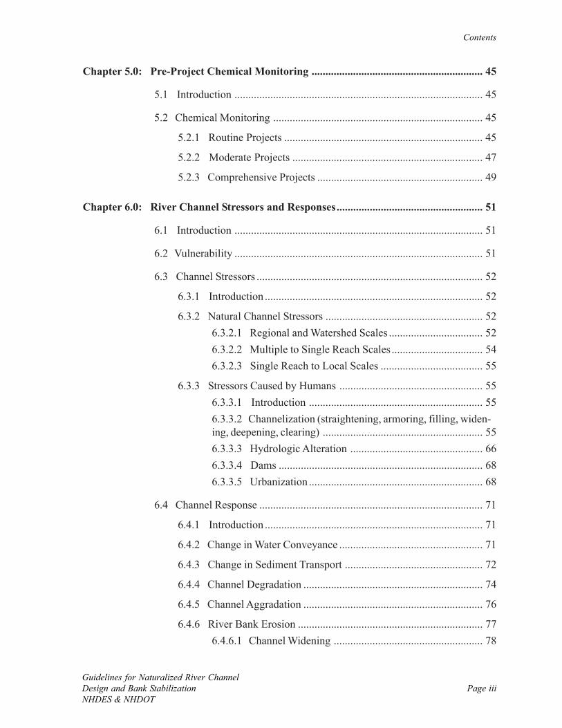
List of Figures ........................................................................................................................ ix
List of Tables ........................................................................................................................ xiii
Acknowledgments ................................................................................................................. xv
Chapter 1.0: Introduction .................................................................................................... 1
1.1 Guidelines Overview ............................................................................... 1
1.2 Applicability and Accompanying Materials ............................................. 4
1.3 A Comment on Standardization of Design Methods ............................... 5
1.4 River Management Axioms ..................................................................... 6
Chapter 2.0: Understanding the Project via Classification .............................................. 7
2.1 Introduction ............................................................................................ 7
2.2 Goals ..................................................................................................... 10
2.2.1 Created Channel Types .............................................................. 102.2.1.1 Unnatural Rigid Design .............................................. 122.2.1.2 Semi-Natural Form Design ........................................ 132.2.1.3 Natural Process Design .............................................. 14
2.3 Scope .................................................................................................... 15
2.3.1 Regulatory Permits .................................................................... 16
2.3.2 Funding Sources ........................................................................ 16
2.4 Physical Site Constraints ....................................................................... 16
2.5 Ecological Risk ..................................................................................... 17
2.6 Societal Acceptance .............................................................................. 18
2.7 Project Classification ............................................................................ 19
2.7.1 Routine Projects ........................................................................ 19
2.7.2 Moderate Projects ..................................................................... 19
Page iiGuidelines for Naturalized River Channel
Design and Bank StabilizationNHDES & NHDOT
Contents
2.7.3 Comprehensive Projects ............................................................ 20
Chapter 3.0: Initial Assessment and Project Planning .................................................... 21
3.1 Introduction .......................................................................................... 21
3.2 Initial Assessment .................................................................................. 22
3.2.1 Overview ................................................................................... 22
3.2.2 Core Data Requirements ........................................................... 223.2.2.1 Existing Mapping ....................................................... 233.2.2.2 Aerial Photographs ..................................................... 243.2.2.3 Hydrology and Hydraulic Information ....................... 253.2.2.4 Fluvial Geomorphology ............................................. 263.2.2.5 Biology....................................................................... 273.2.2.6 Chemistry ................................................................... 283.2.2.7 Previous Studies ......................................................... 30
3.3 Project Planning .................................................................................... 31
3.3.1 Problem Identification ............................................................... 31
3.3.2 Goals and Objectives ................................................................. 323.3.2.1 Overview .................................................................... 323.3.2.2 Discussion of Goals ................................................... 333.3.2.3 Stakeholder Involvement ........................................... 33
3.3.3 Design Overview ....................................................................... 34
3.3.4 Implementation .......................................................................... 34
3.3.5 Evaluation and Management ..................................................... 36
Chapter 4.0: Pre-Project Biological Monitoring .............................................................. 37
4.1 Introduction .......................................................................................... 37
4.2 Biomonitoring ....................................................................................... 39
4.2.1 Routine Projects ........................................................................ 39
4.2.2 Moderate Projects ..................................................................... 40
4.2.3 Comprehensive Projects ............................................................ 42
4.3 Physical Habitat Assessment ................................................................. 43
Page iiiGuidelines for Naturalized River ChannelDesign and Bank StabilizationNHDES & NHDOT
Contents
Chapter 5.0: Pre-Project Chemical Monitoring .............................................................. 45
5.1 Introduction .......................................................................................... 45
5.2 Chemical Monitoring ............................................................................ 45
5.2.1 Routine Projects ........................................................................ 45
5.2.2 Moderate Projects ..................................................................... 47
5.2.3 Comprehensive Projects ............................................................ 49
Chapter 6.0: River Channel Stressors and Responses..................................................... 51
6.1 Introduction .......................................................................................... 51
6.2 Vulnerability .......................................................................................... 51
6.3 Channel Stressors .................................................................................. 52
6.3.1 Introduction ............................................................................... 52
6.3.2 Natural Channel Stressors ......................................................... 526.3.2.1 Regional and Watershed Scales .................................. 526.3.2.2 Multiple to Single Reach Scales ................................. 546.3.2.3 Single Reach to Local Scales ..................................... 55
6.3.3 Stressors Caused by Humans .................................................... 556.3.3.1 Introduction ............................................................... 556.3.3.2 Channelization (straightening, armoring, filling, widen-ing, deepening, clearing) .......................................................... 556.3.3.3 Hydrologic Alteration ................................................ 666.3.3.4 Dams .......................................................................... 686.3.3.5 Urbanization ............................................................... 68
6.4 Channel Response ................................................................................. 71
6.4.1 Introduction ............................................................................... 71
6.4.2 Change in Water Conveyance .................................................... 71
6.4.3 Change in Sediment Transport .................................................. 72
6.4.4 Channel Degradation ................................................................. 74
6.4.5 Channel Aggradation ................................................................. 76
6.4.6 River Bank Erosion ................................................................... 776.4.6.1 Channel Widening ...................................................... 78
Page ivGuidelines for Naturalized River Channel
Design and Bank StabilizationNHDES & NHDOT
Contents
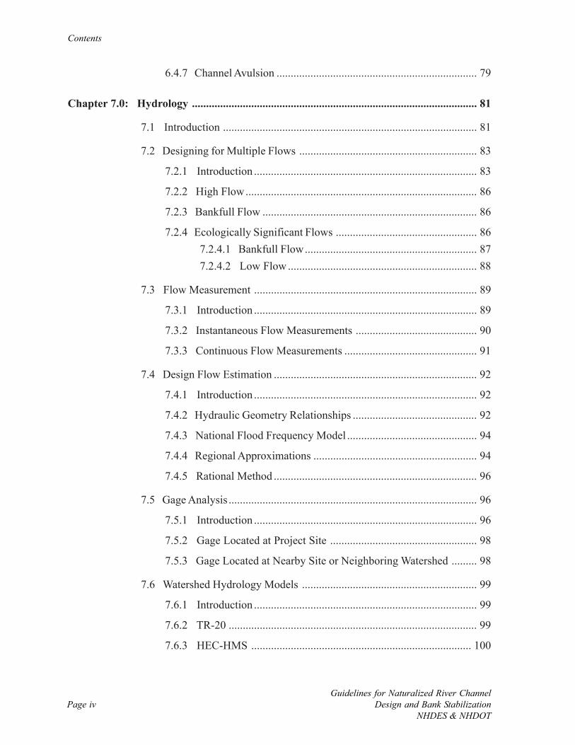
6.4.7 Channel Avulsion ....................................................................... 79
Chapter 7.0: Hydrology ..................................................................................................... 81
7.1 Introduction .......................................................................................... 81
7.2 Designing for Multiple Flows ............................................................... 83
7.2.1 Introduction ............................................................................... 83
7.2.2 High Flow.................................................................................. 86
7.2.3 Bankfull Flow ............................................................................ 86
7.2.4 Ecologically Significant Flows .................................................. 867.2.4.1 Bankfull Flow............................................................. 877.2.4.2 Low Flow ................................................................... 88
7.3 Flow Measurement ............................................................................... 89
7.3.1 Introduction ............................................................................... 89
7.3.2 Instantaneous Flow Measurements ........................................... 90
7.3.3 Continuous Flow Measurements ............................................... 91
7.4 Design Flow Estimation ........................................................................ 92
7.4.1 Introduction ............................................................................... 92
7.4.2 Hydraulic Geometry Relationships ............................................ 92
7.4.3 National Flood Frequency Model .............................................. 94
7.4.4 Regional Approximations .......................................................... 94
7.4.5 Rational Method ........................................................................ 96
7.5 Gage Analysis ........................................................................................ 96
7.5.1 Introduction ............................................................................... 96
7.5.2 Gage Located at Project Site .................................................... 98
7.5.3 Gage Located at Nearby Site or Neighboring Watershed ......... 98
7.6 Watershed Hydrology Models .............................................................. 99
7.6.1 Introduction ............................................................................... 99
7.6.2 TR-20 ........................................................................................ 99
7.6.3 HEC-HMS .............................................................................. 100
Page vGuidelines for Naturalized River ChannelDesign and Bank StabilizationNHDES & NHDOT
Contents
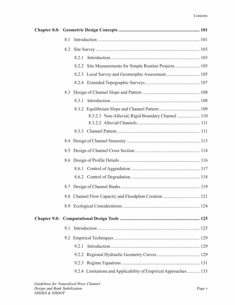
Chapter 8.0: Geometric Design Concepts ...................................................................... 101
8.1 Introduction ........................................................................................ 101
8.2 Site Survey .......................................................................................... 103
8.2.1 Introduction ............................................................................. 103
8.2.2 Site Measurements for Simple Routine Projects ..................... 105
8.2.3 Local Survey and Geomorphic Assessment............................. 105
8.2.4 Extended Topographic Surveys ............................................... 107
8.3 Design of Channel Slope and Pattern ................................................. 108
8.3.1 Introduction ............................................................................. 108
8.3.2 Equilibrium Slope and Channel Pattern ................................... 1098.3.2.1 Non-Alluvial, Rigid Boundary Channel ................... 1108.3.2.2 Alluvial Channels ...................................................... 111
8.3.3 Channel Pattern ....................................................................... 111
8.4 Design of Channel Sinuosity ............................................................... 113
8.5 Design of Channel Cross Section ........................................................ 114
8.6 Design of Profile Details ..................................................................... 116
8.6.1 Control of Aggradation ........................................................... 117
8.6.2 Control of Degradation ........................................................... 118
8.7 Design of Channel Banks .................................................................... 119
8.8 Channel Flow Capacity and Floodplain Creation ................................ 121
8.9 Ecological Considerations................................................................... 124
Chapter 9.0: Computational Design Tools ..................................................................... 125
9.1 Introduction ........................................................................................ 125
9.2 Empirical Techniques .......................................................................... 129
9.2.1 Introduction ............................................................................. 129
9.2.2 Regional Hydraulic Geometry Curves ..................................... 129
9.2.3 Regime Equations ................................................................... 131
9.2.4 Limitations and Applicability of Empirical Approaches........... 133
Page viGuidelines for Naturalized River Channel
Design and Bank StabilizationNHDES & NHDOT
Contents
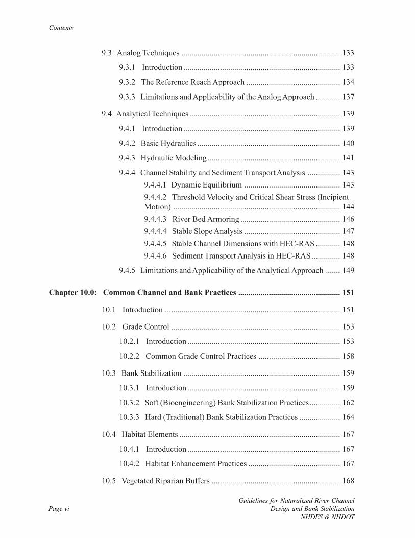
9.3 Analog Techniques .............................................................................. 133
9.3.1 Introduction ............................................................................. 133
9.3.2 The Reference Reach Approach .............................................. 134
9.3.3 Limitations and Applicability of the Analog Approach ............ 137
9.4 Analytical Techniques .......................................................................... 139
9.4.1 Introduction ............................................................................. 139
9.4.2 Basic Hydraulics ...................................................................... 140
9.4.3 Hydraulic Modeling ................................................................. 141
9.4.4 Channel Stability and Sediment Transport Analysis ................ 1439.4.4.1 Dynamic Equilibrium ............................................... 1439.4.4.2 Threshold Velocity and Critical Shear Stress (IncipientMotion) .................................................................................. 1449.4.4.3 River Bed Armoring ................................................. 1469.4.4.4 Stable Slope Analysis ............................................... 1479.4.4.5 Stable Channel Dimensions with HEC-RAS ............ 1489.4.4.6 Sediment Transport Analysis in HEC-RAS.............. 148
9.4.5 Limitations and Applicability of the Analytical Approach ....... 149
Chapter 10.0: Common Channel and Bank Practices .................................................. 151
10.1 Introduction ...................................................................................... 151
10.2 Grade Control ................................................................................... 153
10.2.1 Introduction ........................................................................... 153
10.2.2 Common Grade Control Practices ........................................ 158
10.3 Bank Stabilization ............................................................................. 159
10.3.1 Introduction ........................................................................... 159
10.3.2 Soft (Bioengineering) Bank Stabilization Practices............... 162
10.3.3 Hard (Traditional) Bank Stabilization Practices .................... 164
10.4 Habitat Elements ............................................................................... 167
10.4.1 Introduction ........................................................................... 167
10.4.2 Habitat Enhancement Practices ............................................. 167
10.5 Vegetated Riparian Buffers ............................................................... 168
Page viiGuidelines for Naturalized River ChannelDesign and Bank StabilizationNHDES & NHDOT
Contents
Chapter 11.0: Implementation ........................................................................................ 171
11.1 Introduction ...................................................................................... 171
11.2 Regulatory Permits and Reviews ...................................................... 171
11.2.1 Introduction ........................................................................... 171
11.2.2 Pre-application Meetings ....................................................... 174
11.2.3 Federal Permit Summary ....................................................... 174
11.2.4 New Hampshire Permits and Reviews ................................... 176
11.3 Funding ............................................................................................. 179
11.3.1 Introduction ........................................................................... 179
11.3.2 Fund Raising .......................................................................... 181
11.4 Land Rights and Access .................................................................... 182
11.5 Construction Phase ........................................................................... 183
11.5.1 Introduction ........................................................................... 183
11.5.2 Construction Administration.................................................. 185
11.5.3 Construction Inspection ........................................................ 186
Chapter 12.0: Evaluation and Management .................................................................. 187
12.1 Introduction ...................................................................................... 187
12.2 Project Evaluation Methods.............................................................. 190
12.2.1 Introduction ........................................................................... 190
12.2.2 Physical (Stability) Monitoring .............................................. 191
12.2.3 Biological Monitoring ........................................................... 193
12.2.4 Chemical Monitoring ............................................................. 195
12.2.5 Monitoring Downstream Effects ........................................... 196
12.3 Project Management ......................................................................... 196
12.3.1 Introduction ........................................................................... 196
12.3.2 Operation and Maintenance................................................... 197
12.3.3 Adaptive Management ........................................................... 197
Page viiiGuidelines for Naturalized River Channel
Design and Bank StabilizationNHDES & NHDOT
Contents
Chapter 13.0: River Crossings, Dams, and Natural Flows ........................................... 199
13.1 Introduction ...................................................................................... 199
13.2 River Crossings ................................................................................. 199
13.3 Dam Removal ................................................................................... 200
13.4 Natural Instream Flows..................................................................... 201
Appendix A: Checklists of Common Steps Performed During Naturalized ChannelDesign and Bank Stabilization Projects ............................................................................ 203
Appendix B: New Hampshire Photo Documentation Procedure ................................. 207
Appendix C: New Hampshire Gage Network and HUC-10 Codes .............................. 215
Appendix D: National Flood Frequency Hydrology Model for New Hampshire ....... 221
Appendix E: Charts for Determining Stable Equilibrium Slope ................................. 225
Appendix F: Charts for Determining Threshold Velocity ............................................. 229
Appendix G: New Hampshire Designated Rivers Under RSA 483 .............................. 233
Glossary of Technical Terms .............................................................................................. 237
List of References ................................................................................................................ 269
Page ixGuidelines for Naturalized River ChannelDesign and Bank StabilizationNHDES & NHDOT
FIGURES
Figure 2-1: Project classification as routine, moderate, or comprehensive based on goals,scope, site constraints, ecological risk, and societal acceptance. .............................................. 9
Figure 2-2: Photograph of an unnatural rigid design component on the Mad River inCompton, NH that was installed with minimal planning to fortify a rapidly eroding bank(Source: DES). ...................................................................................................................... 12
Figure 2-3: Photograph of a semi-natural form design on the Piscataquog River in NewBoston, NH where a rock vortex weir (pictured above) and rock groins, or barbs, were usedto limit erosion, protect infrastructure, and improve habitat (Source: MMI). ....................... 13
Figure 2-4: Schematic of a natural process design plan for the Mohawk River in Colebrook,NH where flow in the straightened channel is returned to abandoned side channels (Source:Field Geology Services). ......................................................................................................... 14
Figure 4-1: Pre-project biological monitoring recommendations for routine, moderate, andcomprehensive projects. .......................................................................................................... 38
Figure 5-1: Pre-project chemical monitoring recommendations for routine, moderate, andcomprehensive projects. .......................................................................................................... 46
Figure 6-1: Schematic of a floodplain encroachment stressor, and the anticipated responsesas categorized by advantages and disadvantages (Source: MacBroom, 1998). ..................... 57
Figure 6-2: Schematic of a channel filling stressor, and the anticipated responses as catego-rized by advantages and disadvantages (Source: MacBroom, 1998). ................................... 58
Figure 6-3: Schematic of a channel straightening stressor, and the anticipated responses ascategorized by advantages and disadvantages (Source: MacBroom, 1998). ......................... 60
Figure 6-4: Schematic of a riprap armoring stressor, and the anticipated responses as catego-rized by advantages and disadvantages (Source: MacBroom, 1998). ................................... 61
Figure 6-5: Schematic of a rigid lining stressor, and the anticipated responses as categorizedby advantages and disadvantages (Source: MacBroom, 1998). ............................................ 62
Figure 6-6: Schematic of a channel widening stressor, and the anticipated responses ascategorized by advantages and disadvantages (Source: MacBroom, 1998). ......................... 63
Figure 6-7: Schematic of a channel deepening stressor, and the anticipated responses ascategorized by advantages and disadvantages (Source: MacBroom, 1998). ......................... 64
Page xGuidelines for Naturalized River Channel
Design and Bank StabilizationNHDES & NHDOT
Figures
Figure 6-8: Schematic of a channel clearing stressor, and the anticipated responses as catego-rized by advantages and disadvantages (Source: MacBroom, 1998). ................................... 65
Figure 6-9: Schematic of a channel relocation stressor, and the anticipated responses ascategorized by advantages and disadvantages (Source: MacBroom, 1998). ......................... 67
Figure 6-10: Schematic of a dam stressor, and the anticipated responses as categorized byadvantages and disadvantages (Source: MacBroom, 1998). ................................................. 69
Figure 6-11: Pre- and post-development hydrographs that show an increase in runoff andhigher peak flows following a change in land use (Source: EPA, 1997). ............................... 70
Figure 6-12: Excessive aggradation upstream of an undersized bridge on the West Branch ofthe Little River in Stowe, VT (Source: MMI). The photograph is taken looking downstream.The bridge opening is smaller than the current bankfull width of the channel. Hydraulicmodeling indicates that backwatering takes place in this location under bankfull and largerstorms. .................................................................................................................................... 72
Figure 6-13: The affects of altered sediment transport rates and channel boundary conditionson stability. Bold text indicates most likely processes influencing the river channel. ............. 73
Figure 6-14: Photograph of channel degradation and widening on Warren Brook in Alstead,NH (Source: Horizons Engineering, LLC). ........................................................................... 74
Figure 6-15: Photograph of an eroding bank associated with channel degradation on WarrenBrook in Alstead, NH (Source: Horizons Engineering, LLC). Inset photograph shows thesame bank following stabilization with riprap and grass. ........................................................ 75
Figure 6-16: Photograph of an aggradational feature at the confluence of Bowers Brook andCold River in Acworth, NH taken in August 2006 (Source: Horizons Engineering, LLC). .. 76
Figure 6-17: Aerial photograph of the 2006 Suncook River channel avulsion in Epsom, NH(Source: USACOE). .............................................................................................................. 80
Figure 7-1: Hydrologic calculation (blue text) and measurement (green text) recommenda-tions for routine, moderate, and comprehensive projects. ...................................................... 82
Figure 7-2: Typical schematic of a natural(ized) channel with compound features includinglow-flow channel, bankfull channel, and the low and high terraces of the floodplain. ............ 84
Figure 7-3: Factors, both natural and caused by humans, that influence river hydrology. .... 85
Figure 7-4: Photograph of an instrument housing that contains a temporary, continuousmonitoring river gage (Source: MMI). .................................................................................. 91
Page xiGuidelines for Naturalized River ChannelDesign and Bank StabilizationNHDES & NHDOT
Figures
Figure 7-5: New Hampshire 2005 regional hydraulic geometry curves (provisional), whichare particularly useful for smaller channels in steeper terrain (Source: NHST, 2005). Outlinedcurve is used to estimate bankfull flow. .................................................................................. 93
Figure 7-6: The U.S. Fish and Wildlife Service (FWS) generic New England aquaticbaseflow (ABF) flow hydrograph and default flow (Source: Lang, 1999). ........................... 95
Figure 7-7: Flow chart summarizing the procedure for gage analysis. ................................. 97
Figure 8-1: Geometric design concepts recommended for routine, moderate, and comprehen-sive projects. ......................................................................................................................... 102
Figure 8-2: The relationship between pattern, size, stability, and sediment type for alluvialchannels (Source: FISRWG, 1998 as adapted from Schumm, 1977). .................................. 112
Figure 8-3: Variables used to describe and design meander geometry (Source: FISRWG,1998). .................................................................................................................................... 113
Figure 8-4: The relationship between channel plan, profile, and section (Source: Watson,1999). .................................................................................................................................... 115
Figure 8-5: Distribution of riffles and pools along a meandering thalweg in a meandering (A)and straight (B) channel (Source: Watson, 1999). ............................................................... 117
Figure 8-6: Photograph of a river bank on Warren Brook in Alstead, NH with approximatelocations of the low, mid, and upper bank (Source: Horizons Engineering, LLC). ............. 119
Figure 8-7: Example of a cross section design in HEC-RAS to concentrate low flows,increase sediment transport in the bankfull channel, and establish a flood bench within anincised channel. ..................................................................................................................... 123
Figure 9-1: Computational tools recommended for routine, moderate, and comprehensiveprojects. ................................................................................................................................ 126
Figure 9-2: General guidance for creating a stable naturalized channel for non-alluvial andalluvial channels. ................................................................................................................... 128
Figure 9-3: New Hampshire 2005 regional hydraulic geometry curves (provisional), whichare particularly useful for smaller channels in steeper terrain (Source: NHST, 2005). Outlinedcurves are used to estimate bankfull width, depth, and cross sectional flow area. ............... 130
Figure 9-4: Longitudinal zones of a river corridor (Source: Schumm, 1977; FISRWG,1998). .................................................................................................................................... 135
Page xiiGuidelines for Naturalized River Channel
Design and Bank StabilizationNHDES & NHDOT
Figures
Figure 9-5: Montgomery and Buffington channel classification system primarily based onlongitudinal watershed position (Source: Montgomery and Buffington, 1997). .................. 135
Figure 9-6: Rosgen channel classification system based on slope, sinuosity, width to depthratio, entrenchment ratio, and dominant bed material (Source: Rosgen, 1994; Rosgen andSilvey, 1996). ........................................................................................................................ 136
Figure 9-7: A schematic of the Simon incised channel evolution model (Source: Simon,1989; FISRWG, 1998). ......................................................................................................... 138
Figure 9-8: The dynamic equilibrium between sediment and water in river channels (Source:Lane, 1955; Rosgen and Silvey, 1996). ................................................................................. 143
Figure 9-9: Critical shear stress versus particle grain size diameter (Source: Leopold et al.,1964). .................................................................................................................................... 147
Figure 10-1: General procedure for selecting a type of bank stabilization practice. ........... 161
Figure 10-2: “Chasing the river” photograph where attempts to stop bank erosion withriprap lead to more erosion downstream on the Nooksack River, WA (Source: Field GeologyServices). .............................................................................................................................. 165
Figure 11-1: Common state (blue), federal (green), and local (red) permit requirements fornaturalized channel design and bank stabilization projects in New Hampshire (After OMNR,2001). Solid arrows indicate permits typically applicable in the location, while dashed linesrepresent locations where permits could be required. In New Hampshire, the river corridor isgenerally considered to be 1,320 feet wide, as defined for designated rivers in the RiversManagement and Protection Act (RSA 483). ....................................................................... 172
Figure 12-1: Recommendations for evaluation and management for routine, moderate, andcomprehensive projects. ........................................................................................................ 188
Page xiiiGuidelines for Naturalized River ChannelDesign and Bank StabilizationNHDES & NHDOT
TABLES
Table 2-1: Possible responses to project classification questions (A) and definition of classifi-cation categories (B). ................................................................................................................ 8
Table 2-2: Classification of different types of created river channels, including the fluvialgeomorphology, habitat, design, and social aspects of each. .................................................. 11
Table 3-1: Example of a preliminary alternatives matrix that is useful for exploration ofproject options, ruling out alternatives that are clearly not feasible, and selecting a sub-set ofalternatives that should be considered for further analysis. ..................................................... 35
Table 6-1: Examples of physically vulnerable channel types or features, and the associatedthreats to river ecology, infrastructure, and social values. ...................................................... 52
Table 6-2: Natural channel stressors at multiple scales. ........................................................ 53
Table 6-3: Potential stressors caused by humans, and likely watershed and channel responses................................................................................................................................................. 56
Table 7-1: Key function and appropriate design flow for each element of a natural(ized)channel. ................................................................................................................................... 83
Table 7-2: Common discharge per watershed area (cfsm) for different flow scenarios.Bankfull flow estimates calculated from the New Hampshire hydraulic geometry relationships(HGR) are shown for comparison to regional flow ranges. .................................................... 95
Table 8-1: Design recommendations for non-alluvial and alluvial channels. ....................... 103
Table 8-2: Typical ranges of channel slopes for different profile forms, and the expecteddominant particles on the bed (Source: Montgomery and Buffington, 1997; Rosgen andSilvey, 1996). ........................................................................................................................ 108
Table 8-3: Sediment transport equations and charts for estimating equilibrium channel slope............................................................................................................................................... 109
Table 8-4: Recommendations for maximum bank angles. ................................................... 121
Table 9-1: Examples of regime equations that are useful in naturalized channel design andbank stabilization projects to estimate stable channel dimensions. ....................................... 132
Page xivGuidelines for Naturalized River Channel
Design and Bank StabilizationNHDES & NHDOT
Tables
Table 9-2: Permissible shear stress and threshold velocity for different soil particle sizes andvarious materials used in naturalized channel design and bank stabilization (Source:Fischenich, 2001). Note that RECPs represents rolled erosion control products. ............... 145
Table 9-3: Equations for determining threshold velocity (A) and critical shear stress (B). 146
Table 10-1: Common channel and bank practices for a given application, and referencescontaining application details. Note that all references are available in the accompanyingelectronic document library. .................................................................................................. 152
Table 10-2: Functions of common channel and bank practices (Source: MDE, 2000). ..... 154
Table 10-3: Site conditions suitable for common channel and bank practices (Source: MDE,2000). .................................................................................................................................... 156
Table 11-1: Common sources of funding for naturalized channel design and bank stabilizationprojects in New Hampshire. .................................................................................................. 180
Page xvGuidelines for Naturalized River ChannelDesign and Bank StabilizationNHDES & NHDOT
ACKNOWLEDGMENTS
Many people made important contributions to this guidelines document that greatly improved
the end product. As a whole, the New Hampshire Stream Team offered important direction
and decision-making at the beginning stages that ultimately formed the structure of the
document. The time given to the several rounds of edits yielded many helpful comments, the
majority of which were directly or indirectly incorporated into the document.
We thank each reviewer for your contributions to this guidelines document, the accompanying
white paper, and the electronic library, and hope that all will serve as valuable tools to your
naturalized channel design and bank stabilization projects.
Sincerely,
Project Sponsors
Steven M. Couture, Rivers Coordinator, NH Department of Environmental Services
Kevin Nyhan, Senior Environmental Manager, NH Department of Transportation
Authors
Roy Schiff, Water Resource Scientist and Engineer, Milone & MacBroom, Inc.
James G. MacBroom, Senior Vice President, Milone & MacBroom, Inc.
Jeanine Armstrong Bonin, Vice President of Water Resources, Milone & MacBroom, Inc.
CONTRIBUTORS
Matthew Carpenter, Fisheries Biologist, NH Fish and Game
John Field, Fluvial Geomorphologist, Field Geology Services
Robert H. Flynn, NH/VT District, US Geological Survey
C. Wayne Ives, Instream Flow Specialist, NH Department of Environmental Services
Steve Landry, Merrimack Watershed Supervisor, NH Department of Environmental Services
Page xviGuidelines for Naturalized River Channel
Design and Bank StabilizationNHDES & NHDOT
Acknowledgments
Deborah Loiselle, River Restoration Coordinator, NH Department of Environmental Services
Bethann MacCarthy, Civil Engineer, NH Department of Environmental Services
James MacCartney, Restoration Specialist, National Park Service and Trout Unlimited
John Magee, Fish Habitat Biologist, NH Fish and Game
Adair Mulligan, Conservation Director, Connecticut River Joint Commissions
Scott A. Olson, NH/VT District, US Geological Survey
Gregory Penta, Permit Specialist, US Army Corps of Engineers
Mark Prout, White Mountain National Forest Fisheries Biologist, US Forest Service
Craig Rennie, Land Resource Specialist, NH Department of Environmental Services
David L. Scott, In-House Design Chief, NH Department of Transportation, Bureau of Bridge
Design
Mary Ann Tilton, Wetlands Bureau Asst. Administrator, NH Department of Environmental
Services
Ted Walsh, Water Quality Specialist, NH Department of Environmental Services
Page 1Guidelines for Naturalized River ChannelDesign and Bank StabilizationNHDES & NHDOT
CHAPTER 1.0: INTRODUCTION
1.1 Guidelines Overview
The practice of naturalized river channel design and bank stabilization has expanded over the
past several decades, and a lot of work has been done to improve both theory and application.
The practitioner can now draw from an expanded toolbox containing a broad range of well-
established empirical, analog, and analytical design methods. The continually growing
knowledge in applied local rehabilitation and enhancement, and full system restoration has led
to an expanded set of available design procedures and tools. To address the challenge of
selecting appropriate design methods for each unique project – the art associated with the
science of naturalized river channel design and bank stabilization – a project classification
system is presented that is based on the project goals, scope, physical site constraints,
ecological risks, and likely level of societal acceptance. Classification of a project as routine,
moderate, or comprehensive informs the planning process, guides selection of design
methods, supports project implementation, and increases the chances for meeting goals and
objectives.
Classification of routine, moderate, and comprehensive projects is described in Chapter 2.0,
and examples of each are given. The project categories guide the selection of the appropriate
design and monitoring. For topics that should primarily be considered according to whether a
project is routine, moderate, or comprehensive, a flow chart is presented at the beginning of
the chapter that directs the reader to the recommended design or monitoring methodology.
The text within the chapters contains method details and reference to existing information.
Chapter 3.0 presents core data requirements that should be collected during the initial
assessment of all naturalized river channel design and bank stabilization projects. This basic
information can directly inform design on routine projects, and serve as the basis for
additional data collections for moderate and comprehensive projects. In addition, findings of
Chapter 1.0
Page 2Guidelines for Naturalized River Channel
Design and Bank StabilizationNHDES & NHDOT
an initial assessment provide information to begin the typical project planning sequence –
problem identification, determination of goals and objectives, design, project implementation,
evaluation and management. There are situations, such as when an emergency repair is
needed following a flood, when a complete initial assessment may not be possible, but as
much of the recommended data should be collected as possible. For example, quick drainage
area calculations from topographic maps can facilitate the use of regional curves that can
guide emergency response to damaging flood events. It may be possible to collect some of
the initial assessment data in advance of such events in anticipation that they will eventually
occur and to be better prepared to respond.
All management activities can influence the biology and chemistry of rivers, and thus it is
important to have some understanding of species or water quality parameters targeted for
improvement before project implementation. Chapters 4.0 (biology) and 5.0 (chemistry)
contain pre-project monitoring recommendations where biological and chemical recovery are
included in project goals. The classification of the project as routine, moderate, or
comprehensive, in addition to the specific project goals and objectives, guide the level of pre-
project assessment. For example, pre-project biological and chemical monitoring is typically
minimal for small routine projects where the main goal is infrastructure protection while
comprehensive projects often include multiple rounds of data collections. Current monitoring
protocols suggest that substantial time and funding is needed in order to confirm biological or
chemical change following a river management activity; however, these resources are often
not available. Scaled back monitoring recommendations are presented here that fit into the
typical duration and funding of current projects. The monitoring recommendations will likely
expand in the future as the desire to evaluate project effectiveness through pre- and post-
project monitoring continues to grow.
Chapter 6.0 describes the primary types of river channel distress encountered in New
Hampshire, and throughout the New England region of the United States. Accurate problem
identification is the most important aspect of naturalized river channel design and bank
stabilization project as self-sustaining solutions hinge on a good understanding of the sources
Introduction
Page 3Guidelines for Naturalized River ChannelDesign and Bank StabilizationNHDES & NHDOT
of impairment. Field indicators of typical types of channel distress are presented to guide
problem identification.
The fundamental parts of designing naturalized river channel or bank stabilization projects are
hydrology (Chapter 7.0), geometric design considerations (Chapter 8.0), and computational
tools (Chapter 9.0) – each used together to perform the alternatives analysis required for
effective design. The combination of approaches and methods is a function of the type of
project and whether a project is classified as routine, moderate, or comprehensive. In other
words, the goals, scope, physical risks, ecological risks, and level of public acceptance
determine the appropriate level of design.
Typical channel and bank practices (Chapter 10.0) used in river management projects are
described in many existing manuals, and are referenced here for use in design. The application
notes and specifications cited here can be obtained from the documents in the electronic
library that accompanies these guidelines and is available on the Internet (http://
www.des.state.nh.us/Rivers/). A discussion of selecting the appropriate practice and
important application details for grade control, soft (bioengineering) bank stabilization, hard
(traditional engineering) bank stabilization, habitat features, and riparian zone is presented.
After the design is complete, implementation (Chapter 11.0) takes place once the necessary
permits are obtained and access to the project site is granted. Implementation should begin
with a review of how actual construction will be done and a general plan to deal with
unexpected challenges as they arise. Implementation is concluded with construction
inspection.
Funding for design and implementation can take place in different stages for more involved
moderate and comprehensive projects. If funding for implementation was not in place at the
beginning of the project then additional resources will be needed once the design is complete.
Common funding sources for New Hampshire river management projects, as well as typical
municipal, state, and federal regulatory permitting requirements are presented.
Chapter 1.0
Page 4Guidelines for Naturalized River Channel
Design and Bank StabilizationNHDES & NHDOT
The final aspect of the project is evaluation and management (Chapter 12.0). As with the pre-
project monitoring and design, the appropriate level of project evaluation and available
management options is a function of whether the project is classified as routine, moderate, or
comprehensive. For example, routine projects with limited biological objectives would
receive little post-project monitoring and management, while comprehensive projects with
extensive biological goals should be monitored for longer periods of time and may require
several phases of adaptive management.
Although introduced in separate chapters as individual aspects of naturalized river channel
design and bank stabilization projects, the above components are best treated as an integrated
set. To assist with application of the many design principals presented in this guidelines
document, checklists of common steps to follow for typical naturalized channel design and
bank stabilization projects are presented (Appendix A).
Improving river crossings, removing dams, and establishing natural instream flows are
activities that can increase channel stability and the overall health of aquatic ecosystems.
Although beyond the scope of this guidelines document, these topics are briefly covered
(Chapter 13.0) to summarize existing guidelines used in the State of New Hampshire, in
addition to common practices for the New England region.
1.2 Applicability and Accompanying Materials
This guidelines document is created with specific attention to river management in the State of
New Hampshire, although applicability will extend beyond state limits and even beyond the
region given the widespread use of many of the topics addressed here. Anticipated guidelines
users include those participating in the planning, design, review, or construction of river
management activities with some existing experience in the topic. A comprehensive glossary
of technical terms is included in the back of this document to assist the reader. A white paper
on fluvial geomorphology and river restoration (Schiff et al., 2006) was previously drafted to
Introduction
Page 5Guidelines for Naturalized River ChannelDesign and Bank StabilizationNHDES & NHDOT
review existing manuals and offer guidelines users an overview of the science behind the
applied methods used for naturalized river channel design and bank stabilization projects. The
white paper is available on the Internet at the website of the New Hampshire Department of
Environmental Services (DES), Watershed Management Bureau, River Management and
Protection Program (RMPP) (http://www.des.state.nh.us/rivers/).
The application and theory typically used today for naturalized river channel design and bank
stabilization projects is largely published in a variety of existing manuals
(e.g., NRCS, 1996; FISRWG, 1998; Watson et al., 1999; MDE, 2000; Copeland et al., 2001;
OMNR, 2001; Soar and Thorne, 2001; Flosi et al., 2002; KST, 2002; Cramer et al., 2003;
Doll et al., 2003; Saldi-Caromile et al., 2004; NRCS, 2005). An accompanying electronic
library of documents that are available for public use has been assembled to connect guidelines
users to the appropriate design and background information. The electronic library is
available on the Internet at the DES RMPP website (http://www.des.state.nh.us/rivers/).
1.3 A Comment on Standardization of Design Methods
The consensus on the standardization of monitoring and analyses associated with naturalized
river channel design and bank stabilization methods is that a one-size-fits-all approach is not
possible. The wide variety of problems and solutions, site and watershed conditions, climate,
geography, and other aspects require such a broad range of design sequences that
standardization is complex. Although standardization of detailed design aspects is not
feasible, some generally applicable guidelines are presented here that will help inform routine,
moderate, and comprehensive river management projects. The design recommendation made
here may need fine-tuning based on the specific details of a given project.
Chapter 1.0
Page 6Guidelines for Naturalized River Channel
Design and Bank StabilizationNHDES & NHDOT
1.4 River Management Axioms
Common themes identified during the review of the existing manuals and drafting of the white
paper exposed several fundamental axioms that should be considered throughout naturalized
river channel design and bank stabilization projects.
• Where unconstrained, the natural process design approach is less costly to design and
implement, and more effectively balances the common goals of channel stability and
aquatic habitat improvement.
• Project goals, scope, physical site constraints, ecological risks, and likely level of
societal acceptance guide the type and amount of design, and thus accurately
classifying project type can help with the appropriate selection of design methods.
• Monitoring (baseline, effectiveness, etc…) at some level (even at a very basic level for
small routine projects) should be the first item in the planning process and the last
activity of the project where possible. This will help with accurately identifying the
problem, informing the design, identifying how the local site or reach change, and
evaluating project effectiveness.
• Natural channel stability is not equal to channel immobility. “A stable channel is one
that has neither a net deposition nor net erosion of channel substrate in the long term
(TRANS, 2001).”
• “Work with, not against, a stream’s natural form and function (KST, 2002).”
Page 7Guidelines for Naturalized River ChannelDesign and Bank StabilizationNHDES & NHDOT
CHAPTER 2.0: UNDERSTANDING THE PROJECT VIA CLASSIFICATION
2.1 Introduction
At the beginning of the project, whether it be naturalized river channel design, bank
stabilization, or other activities, a clear understanding of the goals, scope, physical site
constraints, ecological risks, and societal acceptance is crucial. An initial identification of
these five project characteristics supports the planning process (Chapter 3.0), guides pre-
project monitoring (Chapters 4.0 and 5.0), assists with selection of appropriate design tools
(Chapters 7.0 to 10.0), and increases the chances for successful project implementation
(Chapter 11.0 and 12.0).
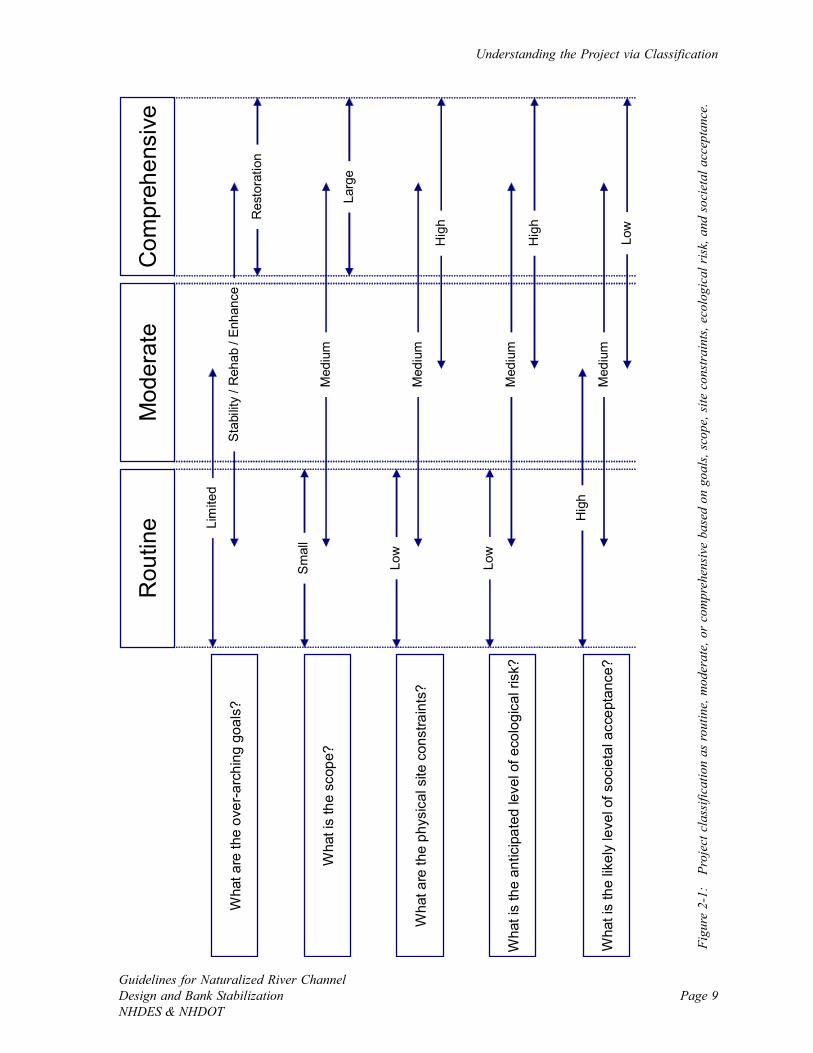
Five questions are presented in this chapter to guide project classification.
1. What are the over-arching goals?
2. What is the scope?
3. What are the physical site constraints?
4. What is the anticipated level of ecological risk?
5. What is the likely level of societal acceptance?
This chapter contains information to assist with answering these questions. Each question
should be occasionally re-visited because an answer to one question will likely add
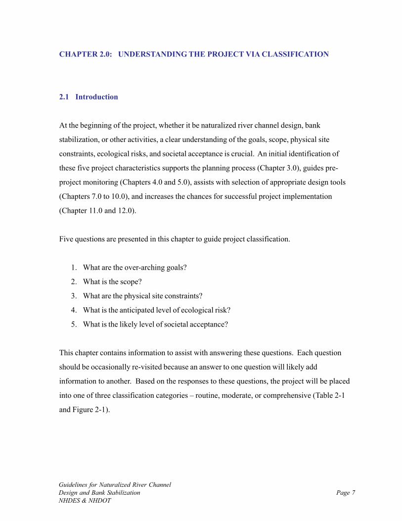
information to another. Based on the responses to these questions, the project will be placed
into one of three classification categories – routine, moderate, or comprehensive (Table 2-1
and Figure 2-1).
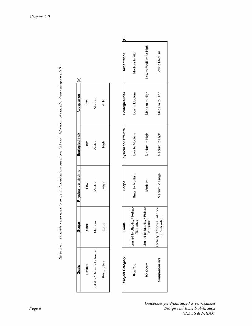
Chapter 2.0
Guidelines for Naturalized River ChannelDesign and Bank Stabilization
NHDES & NHDOTPage 8
Goa
lsSc
ope
Phys
ical
con
stra
ints
Ecol
ogic
al ri
skAc
cept
ance
(A)
Lim
ited
Sm
all
Low
Low
Low
Sta
bilit
y / R
ehab
/ E
nhan
ceM
ediu
mM
ediu
mM
ediu
mM
ediu
m
Res
tora
tion
Larg
eH
igh
Hig
hH
igh
Proj
ect C
ateg
ory
Goa
lsSc
ope
Phys
ical
con
stra
ints
Ecol
ogic
al ri
skAc
cept
ance
(B)
Rou
tine
Lim
ited
to S
tabi
lity
/ Reh
ab
/ Enh
ance
Smal
l to
Med
ium
Low
to M
ediu
mLo
w to
Med
ium
Med
ium
to H
igh
Mod
erat
eLi
mite
d to
Sta
bilit
y / R
ehab
/ E
nhan
ceM
ediu
mM
ediu
m to
Hig
hM
ediu
m to
Hig
hLo
w to
Med
ium
to H
igh
Com
preh
ensi
veSt
abilit
y / R
ehab
/ En
hanc
e to
Res
tora
tion
Med
ium
to L
arge
Med
ium
to H
igh
Med
ium
to H
igh
Low
to M
ediu
m
Tabl
e 2-
1:
Poss
ible
resp
onse
s to
pro
ject
cla
ssifi
catio
n qu
estio
ns (A
) and
def
initi
on o
f cla
ssifi
catio
n ca
tego
ries
(B).
Understanding the Project via Classification
Guidelines for Naturalized River ChannelDesign and Bank StabilizationNHDES & NHDOT
Page 9
Mod
erat
eR
outin
eC
ompr
ehen
sive
Wha
t are
the
over
-arc
hing
goa
ls?
Wha
t is
the
scop
e?
Wha
t are
the
phys
ical
site
con
stra
ints
?
Wha
t is
the
antic
ipat
ed le
vel o
f eco
logi
cal r
isk?
Wha
t is
the
likel
y le
vel o
f soc
ieta
l acc
epta
nce?
Lim
ited
Stab
ility
/ R
ehab
/ En
hanc
e
Res
tora
tion
Sm
all
Med
ium
Larg
e
Low
Med
ium
Hig
h
Low
Med
ium
Hig
h
Hig
h
Med
ium
Low
Figu
re 2
-1:
Pro
ject
cla
ssifi
catio
n as
rout
ine,
mod
erat
e, o
r co
mpr
ehen
sive
bas
ed o
n go
als,
scop
e, s
ite c
onst
rain
ts, e
colo
gica
l ris
k, a
nd s
ocie
tal a
ccep
tanc
e.
Chapter 2.0
Guidelines for Naturalized River ChannelDesign and Bank Stabilization
NHDES & NHDOTPage 10
2.2 Goals
What are the over-arching goals of the project?
• Limited: Rapid patches, infrastructure protection, or improve small habitat feature
• Stability, rehabilitation, and enhancement: Natural form-based design with
infrastructure protection and habitat improvement components. Often includes
combination of hard and soft approaches to stabilize banks.
• Restoration: Full restoration of natural form and process
Goal identification requires thinking about planned goals, in addition to those that are
achievable with no or little additional work. There are often biological goals that can readily
be included in projects that primarily address other issues such as channel and bank stability,
infrastructure protection, erosion hazards, and water quality without substantial change in
level of work. Establishment of over-arching project goals often includes the initial phase of
creating specific objectives that define narrower project milestones. Differentiating between
goals and objectives is important as goals are often too broad to measure, and thus specific
objectives are essential for identifying project success.
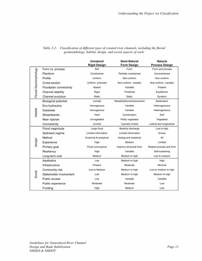
2.2.1 Created Channel Types
An accurate classification of created channel types based on geomorphic characteristics helps
determine the important design principals, biological potential, and the likely social
components of a project (Table 2-2). Many of these aspects of channel design are typically
addressed superficially during the planning process; however, a clear understanding of created
channel types and associated practices such as bank stabilization helps set realistic project
goals and objectives.
Understanding the Project via Classification
Guidelines for Naturalized River ChannelDesign and Bank StabilizationNHDES & NHDOT
Page 11
Unnatural Semi-Natural NaturalRigid Design Form Design Process Design
Form vs. process N/A Form Form and process
Planform Constrained Partially constrained Unconstrained
Profile Uniform Non-uniform Non-uniform
Cross-section Uniform, prismatic Non-uniform, variable Non-uniform, variable
Floodplain connectivity Absent Variable Present
Channel stability Rigid Threshold Equilibrium
Channel evolution Static Static Dynamic
Biological potential Limited Rehabilitation/enhancement Restoration
Eco-hydraulics Homogenous Variable Heterogeneous
Substrate Homogenous Variable Heterogeneous
Streambanks Hard Combination Soft
Near riparian Unvegetated Partly vegetated Vegetated
Connectivity Limited Typically limited Lateral and longitudinal
Flood magnitude Large flood Bankfull discharge Low to high
Sediment regime Limited information Limited information Known
Method Empirical & analytical Analog and analytical All
Experience High Medium Limited
Primary goal Flood conveyance Improve structural form Restore process and form
Resiliency High Variable Self-sustaining
Long-term cost Medium Medium to high Low to medium
Aesthetics Low Medium to high High
Infrastructure Present Moderate Minimal
Community risk Low to Medium Medium to high Low to medium to high
Stakeholder involvement Low Medium to high Medium to high
Public access Low Variable Variable
Public experience Moderate Moderate Low
Funding High Medium Low
Fluv
ial G
eom
orph
olog
yH
abita
tD
esig
nS
ocia
l
Table 2-2: Classification of different types of created river channels, including the fluvialgeomorphology, habitat, design, and social aspects of each.
Chapter 2.0
Guidelines for Naturalized River ChannelDesign and Bank Stabilization
NHDES & NHDOTPage 12
Figure 2-2: Photograph of an unnatural rigid design componenton the Mad River in Compton, NH that was installed with minimal
planning to fortify a rapidly eroding bank (Source: DES).
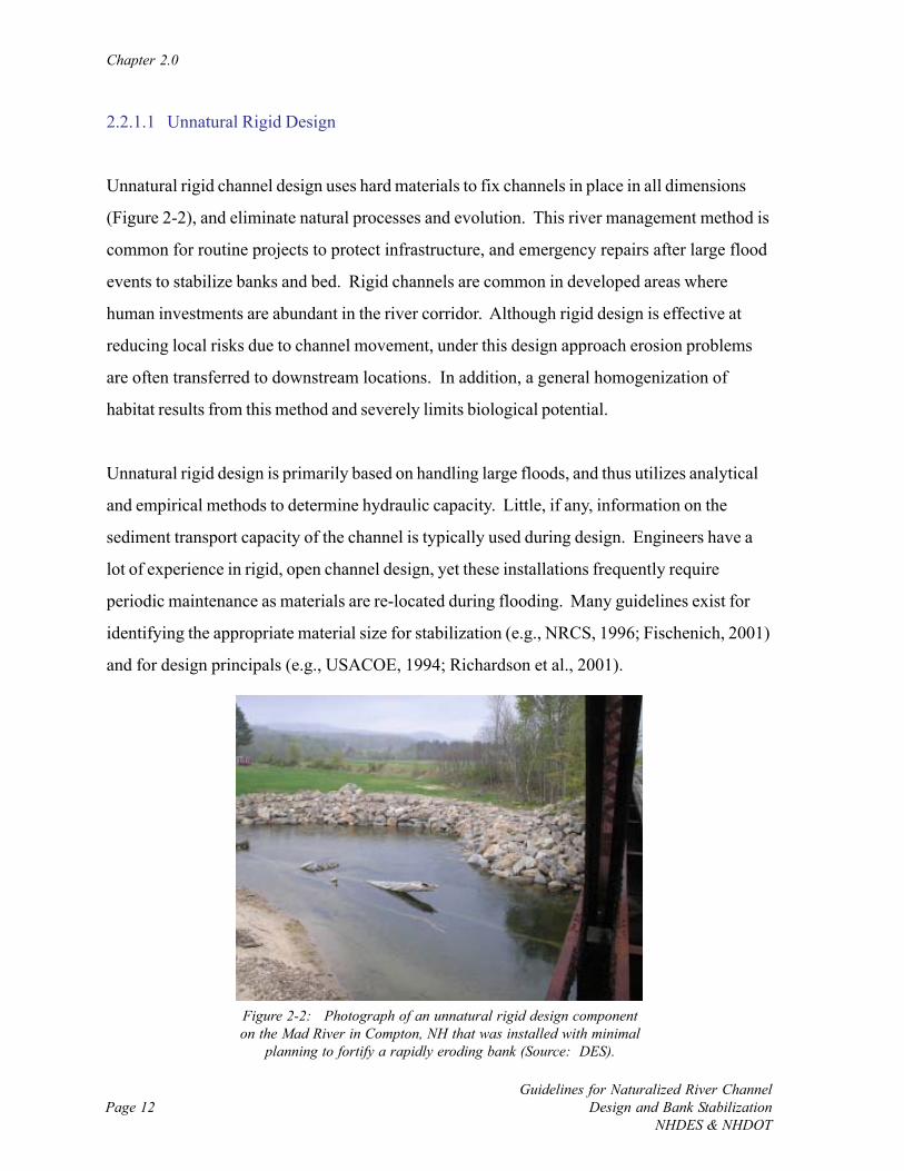
2.2.1.1 Unnatural Rigid Design
Unnatural rigid channel design uses hard materials to fix channels in place in all dimensions
(Figure 2-2), and eliminate natural processes and evolution. This river management method is
common for routine projects to protect infrastructure, and emergency repairs after large flood
events to stabilize banks and bed. Rigid channels are common in developed areas where
human investments are abundant in the river corridor. Although rigid design is effective at
reducing local risks due to channel movement, under this design approach erosion problems
are often transferred to downstream locations. In addition, a general homogenization of
habitat results from this method and severely limits biological potential.
Unnatural rigid design is primarily based on handling large floods, and thus utilizes analytical
and empirical methods to determine hydraulic capacity. Little, if any, information on the
sediment transport capacity of the channel is typically used during design. Engineers have a
lot of experience in rigid, open channel design, yet these installations frequently require
periodic maintenance as materials are re-located during flooding. Many guidelines exist for
identifying the appropriate material size for stabilization (e.g., NRCS, 1996; Fischenich, 2001)
and for design principals (e.g., USACOE, 1994; Richardson et al., 2001).
Understanding the Project via Classification
Guidelines for Naturalized River ChannelDesign and Bank StabilizationNHDES & NHDOT
Page 13
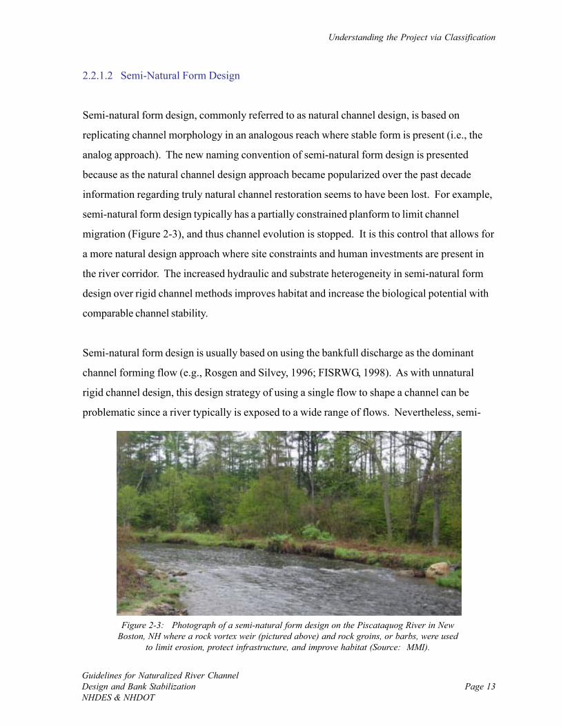
Figure 2-3: Photograph of a semi-natural form design on the Piscataquog River in NewBoston, NH where a rock vortex weir (pictured above) and rock groins, or barbs, were used
to limit erosion, protect infrastructure, and improve habitat (Source: MMI).
2.2.1.2 Semi-Natural Form Design
Semi-natural form design, commonly referred to as natural channel design, is based on
replicating channel morphology in an analogous reach where stable form is present (i.e., the
analog approach). The new naming convention of semi-natural form design is presented
because as the natural channel design approach became popularized over the past decade
information regarding truly natural channel restoration seems to have been lost. For example,
semi-natural form design typically has a partially constrained planform to limit channel
migration (Figure 2-3), and thus channel evolution is stopped. It is this control that allows for
a more natural design approach where site constraints and human investments are present in
the river corridor. The increased hydraulic and substrate heterogeneity in semi-natural form
design over rigid channel methods improves habitat and increase the biological potential with
comparable channel stability.
Semi-natural form design is usually based on using the bankfull discharge as the dominant
channel forming flow (e.g., Rosgen and Silvey, 1996; FISRWG, 1998). As with unnatural
rigid channel design, this design strategy of using a single flow to shape a channel can be
problematic since a river typically is exposed to a wide range of flows. Nevertheless, semi-
Chapter 2.0
Guidelines for Naturalized River ChannelDesign and Bank Stabilization
NHDES & NHDOTPage 14
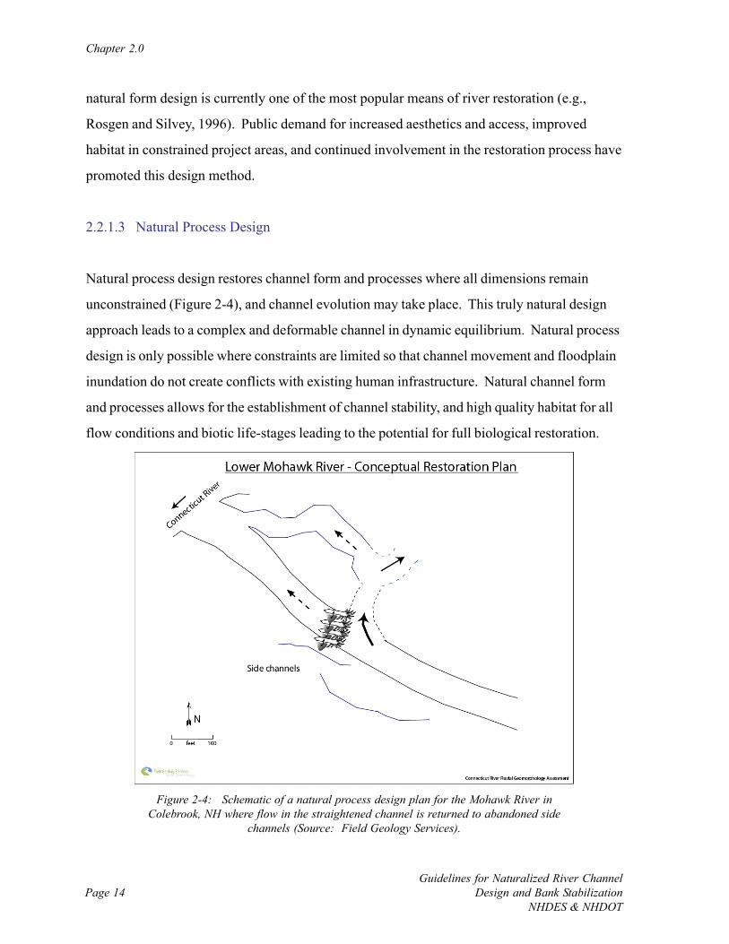
Figure 2-4: Schematic of a natural process design plan for the Mohawk River inColebrook, NH where flow in the straightened channel is returned to abandoned side
channels (Source: Field Geology Services).
natural form design is currently one of the most popular means of river restoration (e.g.,
Rosgen and Silvey, 1996). Public demand for increased aesthetics and access, improved
habitat in constrained project areas, and continued involvement in the restoration process have
promoted this design method.
2.2.1.3 Natural Process Design
Natural process design restores channel form and processes where all dimensions remain
unconstrained (Figure 2-4), and channel evolution may take place. This truly natural design
approach leads to a complex and deformable channel in dynamic equilibrium. Natural process
design is only possible where constraints are limited so that channel movement and floodplain
inundation do not create conflicts with existing human infrastructure. Natural channel form
and processes allows for the establishment of channel stability, and high quality habitat for all
flow conditions and biotic life-stages leading to the potential for full biological restoration.
Understanding the Project via Classification
Guidelines for Naturalized River ChannelDesign and Bank StabilizationNHDES & NHDOT
Page 15
Natural process channel design is comprehensive, covering a range of flows and sediment
regimes, but is simplified due to the absence of physical project constraints. Empirical,
analog, and analytical methods are required to understand how to establish natural process
and form. If properly designed, natural process design should require little to no maintenance,
create minimal risks to humans, and generate valuable flood attenuation and sediment
retention to improve conditions at downstream locations.
Natural process design is usually not possible when infrastructure protection is the main
project goal. In addition, there is a general reluctance to set aside land in the river corridor so
that channels have enough room to move. This has resulted in limited experience and funding
for natural process design projects. The benefits of natural river form and processes are
widely known to include the establishment of stable channels with high quality habitat, and
thus natural process design should be considered where possible.
2.3 Scope
What is the scope of the project?
• Small: Limited funds and rapid corrective action
• Medium: Moderate funding and project duration
• Large: Substantial investment and long-term project
Project scope is often dictated by the permitting requirements and level of funding, which
hopefully are synchronized with the magnitude of the problem being addressed. A small
project scope results from a local scale problem that can be corrected in a short period of time
with limited funding. On the other hand, projects that are large in scope tend to require
substantial funding, have considerable permitting requirements, and can last for a long time.
Chapter 2.0
Guidelines for Naturalized River ChannelDesign and Bank Stabilization
NHDES & NHDOTPage 16
2.3.1 Regulatory Permits
Some combination of federal, state, and local permits is required for naturalized channel
design and bank stabilization activities (Chapter 11.0). An understanding of permitting
requirements is important for accurate project scoping as permit applications can increase
project cost and time period. Regulatory authorities should be contacted during the initial
project classification to identify the required permits for the project.
2.3.2 Funding Sources
Project funding in the State of New Hampshire originates from a variety of sources (Chapter
11.0). While considering project scope it is important to determine if current funds are ample
to accomplish goals. Thinking about funding early in the project planning process will reduce
the chances of using up the project budget before completion that can delay design,
implementation, and effectiveness monitoring. Additional funds will need to be pursued if
funding appears to be too low to address the problem. Expansion of project goals may also
require additional funding.
2.4 Physical Site Constraints
What is the level of physical site constraints associated with the project?
• Low: No infrastructure present in floodprone width
• Medium: Infrastructure present in the floodprone width that is subject to flooding and
erosion hazards
• High: Infrastructure present in the vicinity of the bankfull channel width that is
frequently subject to flooding and erosion hazards
Understanding the Project via Classification
Guidelines for Naturalized River ChannelDesign and Bank StabilizationNHDES & NHDOT
Page 17
The level of risk to infrastructure and personal property is a key factor in determining the
permissible type of design and the required level of detail. For example, a channel creation in
a forested area where physical site constraints are absent would have a low risk of property
damage due to flooding or erosion, and thus deformable boundary conditions and channel
movement would be possible (i.e., a natural process design, see Table 2-2). Channel creation
in a town center, on the other hand, where there is a high risk to infrastructure and personal
property in close proximity to the project site, would likely require a more rigid boundary
condition and immobile channel (i.e., semi-natural form design or unnatural rigid design, see
Table 2-2). Project costs and scope tend to increase with the abundance of physical site
constraints due to expanded design requirements to reduce the risks to the public. Although
site constraints are primarily located near a specific project implementation site, they can also
occur further away (e.g., downstream, distant floodplain, and even upstream) and so each
project should consider potential affects on any other area.
2.5 Ecological Risk
What is the anticipated level of ecological risk?
• Low: Ecological recovery with a resilient and self-sustaining system likely. Limited
chance of additional harm to ecosystem. Complementary multidisciplinary goals.
• Medium: Moderate likelihood for ecological recovery and establishing a resilient and
self-sustaining system. Possibility of short-term harm to ecosystem. Multidisciplinary
project goals may have some inconsistencies.
• High: Ecological recovery with a resilient and self-sustaining system unlikely.
Possibility of long-term harm to ecosystem. Multidisciplinary project goals are in
conflict with each other.
Manipulation of the physical components of river channels and banks create risks to aquatic
habitat and biological assemblages. Issues such as habitat degradation, disruption of life-cycle

Chapter 2.0
Guidelines for Naturalized River ChannelDesign and Bank Stabilization
NHDES & NHDOTPage 18
requirements such as migration paths and spawning gravels, and changes to nearby wetlands
are just some of the concerns to consider when planning a naturalized river channel design or
bank stabilization project. Projects with low ecological risk are likely to recover, have a
resilient and self-sustaining system, and have a limited chance of causing additional harm to
the ecosystem. Such projects typically have biological goals that complement those in other
disciplines. On the other hand, high ecological risk is associated with projects where recovery
is not straight forward, resiliency and a self-sustaining system are not likely, and biological
goals are in conflict with other disciplines. Ecological risk tends to decline with increasing
degrees of natural channel form and processes that are permitted in created channel design
(see Table 2-2).
2.6 Societal Acceptance
What is the likely level of societal acceptance of the project?
• Low: Not a priority project for the public and use of public funds not supported
• Medium: Public interested in project and willing to allocate some public funds
• High: Strong public support of project with willingness of substantial investment and
involvement
The social aspects of a project are important considerations to gain public acceptance,
encourage allocation of public money, and promote future stewardship. In many instances
where projects take place on or adjacent to private lands, public acceptance of a project is
often required for the project to take place at all. In these instances, land-owners should be
involved in the project as planning begins. Low priority projects to the public are often poorly
understood and thus allocation of public funds is more complicated. High priority projects
have the support of a majority of the public, and the problem and solution are understood and
desired. Projects with a high degree of societal acceptance tend to be relatively easy to fund.
Outreach efforts can increase public awareness and acceptance of a project. Note that while
Understanding the Project via Classification
Guidelines for Naturalized River ChannelDesign and Bank StabilizationNHDES & NHDOT
Page 19
the public might enthusiastically support solving a problem, education and outreach may be
needed to gain support or understanding of the most responsible solution.
2.7 Project Classification
The final classification step is to place the project into one of three categories – routine,
moderate, or comprehensive based on the responses to the questions outlined above (see
Table 2-1 and see Figure 2-1). The project category will be referred to throughout this
document to guide design and monitoring. There may be a need to change a project’s
classification as new information becomes available.
2.7.1 Routine Projects
Routine projects mostly have limited goals that fall under localized infrastructure protection
or habitat enhancement. Some routine projects may have expanded goals that include some
aspects of channel stability and local habitat rehabilitation. Project scope is small to medium,
with low to medium physical site constraints and ecological risk. Routine projects take place
at the sub-reach scale, and can be as small as a single geomorphic unit such as a riffle. Public
acceptance of routine projects is medium to high due to public familiarity with patch fixes in
the river corridor. Examples of routine projects include a local bank stabilization to protect
infrastructure, small grade control applications where few structures are present, and
introduction of instream features for fish cover where few structures encroach on floodprone
and erosion hazard areas.
2.7.2 Moderate Projects
In addition to establishing channel stability, moderate projects include rehabilitation or habitat
enhancement goals at approximately the channel reach spatial scale, typically amongst a
medium degree of physical site constraints. Some moderate projects can have more site
Chapter 2.0
Guidelines for Naturalized River ChannelDesign and Bank Stabilization
NHDES & NHDOTPage 20
constraints. The presence of infrastructure leads to medium to high ecological risk as
frequently-used rigid boundaries at this scale can have negative effects on river components
such as near-bank habitat, fish movement, and connectivity. Public acceptance of moderate
projects can decrease due to the larger scope, but is typically medium. Examples of moderate
projects include form-based naturalized channel design, bank stabilization with a combination
of hard and soft practices, and installation of habitat features over a reach where several
structures encroach on floodprone and erosion hazard areas.
2.7.3 Comprehensive Projects
Comprehensive projects are medium to large in scope, and often include one to multiple
reaches. The goals of comprehensive projects can range from channel stability and local
habitat rehabilitation restoration of system processes. Comprehensive projects can have a
high degree of risk if many physical constraints exist in close proximity to the bankfull channel
width. The large project size leads to increased ecological risks as a large initial disturbance is
common during installation of comprehensive projects. Relative to less-involved projects,
public acceptance is typically lower for comprehensive projects since they are less common
and require substantial funds to complete. An example of a comprehensive project is the
restoration of an incised tributary that has unstable channel geometry causing erosion hazards
to nearby homes, excessive sediment delivery to the mainstem river, and poor aquatic habitat.
Solutions of comprehensive projects are often multi-faceted and for this example could in-
clude a combination of active and passive approaches such as natural process and semi-natural
form channel design, application of hard and soft bank stabilization components, installation
of various types of habitat enhancement features, the purchase and demolition of structures in
locations that are permanently prone to flooding and erosion hazards, and the purchase of
easements to preserve open space to give the river channel ample room for lateral adjustment
to limit future conflicts between human investments and river processes.
Page 21Guidelines for Naturalized River ChannelDesign and Bank StabilizationNHDES & NHDOT
CHAPTER 3.0: INITIAL ASSESSMENT AND PROJECT PLANNING
3.1 Introduction
Projects should ideally be conducted in the context of an on-going monitoring program to
inform planning, design, implementation, and evaluation (Ralph and Poole, 2003). However,
this is often not possible due to limited existing monitoring, especially for routine projects
such as local infrastructure protection and habitat enhancement. During the early phases of
project classification and planning, all pertinent existing information such as maps,
photographs, and previous project reports should be assembled. An initial data and field
assessment is needed to confirm accurate classification of the project as routine, moderate, or
comprehensive (Chapter 2.0), and to identify important project planning components (Chapter
3.0). The initial assessment is also important for beginning to expand the understanding of the
problem (Chapter 6.0). The minimum initial assessment data recommendation for all project
types is outlined in Section 3.2. Note that additional data are likely needed to support the
appropriate level of pre-project monitoring (Chapters 4.0 and 5.0), design (Chapters 7.0 to
10.0), and post-project evaluation and management (Chapter 12.0). The initial data collection
during the early stages of projects is typically qualitative and spans the spatial scales from site
to watershed (e.g., site walks and map-based exercises), while subsequent measurements and
observations for design are more detailed and tend to concentrate on the primary project site
up to the reach scale.
The existing planning approaches that are recommended for naturalized channel design and
bank stabilization projects (e.g., FISRWG, 1998; Miller et al., 2001; OMNR, 2001) have many
overlapping components that are applicable to a broad range of projects – problem
identification, drafting of goals and objectives, design, implementation, and evaluation.
Comprehensive projects tend to require a substantial amount of planning while routine
projects can take place with limited planning.
Chapter 3.0
Guidelines for Naturalized River ChannelDesign and Bank Stabilization
NHDES & NHDOTPage 22
3.2 Initial Assessment
3.2.1 Overview
An initial collection of physical, biological, and chemical data will help gain a better
understanding of the problem, refine goals and objectives, identify future data collection
needs, and establish baseline conditions. The initial assessment should begin with a broad
evaluation of watershed, reach, and site hydrology and sediment regime. Departure from the
balance between sediment and water (Lane, 1955) is often the primary mechanism leading to
channel instability and degraded aquatic habitat. The channel geomorphology component of
the initial assessment should produce an initial estimation of the expected river channel type
for the given valley, the general planform based on longitudinal slope and discharge, likely
cross section dimensions, the current stage of channel evolution, and the most likely sources
of current and historical channel distress. Aquatic habitat is briefly evaluated to gain an
understanding of the channel response to the stressors and how the project can have the most
biological benefit. Where applicable, species targeted for recovery are also identified to
establish baseline population estimates. Finally, an initial understanding of water and sediment
quality can identify existing chemical impairment.
3.2.2 Core Data Requirements
Virtually all river management projects require an initial assessment that begins with gathering
and reviewing existing data followed by a site visit to view field conditions. During the initial
site visit, take photographs to qualitatively document existing conditions. New Hampshire
Department of Environmental Services (DES) has a photo documentation procedure
(Appendix B) that offers useful guidance and repeatable methods. The intent of the initial
assessment is to begin to understand river and watershed conditions with available
information, and to identify the type of detailed information that will be needed for design.
Initial Assessment and Project Planning
Guidelines for Naturalized River ChannelDesign and Bank StabilizationNHDES & NHDOT
Page 23
The following data generally exist for most rivers in New Hampshire and can be obtained
from various websites, libraries, and state offices.
3.2.2.1 Existing Mapping
Site maps are necessary to identify the project location relative to watershed features and
municipal boundaries, and to identify land use/cover in the watershed. Topographic maps
with contour lines depict the site’s elevation, land slope, relief, and cultural features.
Topographic maps can also be used to delineate watersheds, measure river channel length,
compute sinuosity and channel slope, and view location of wetlands, lakes, ponds, roads and
bridges.
Topographic maps are available from the US Geological Survey (USGS) and can be found in
libraries and selected bookstores. Digital maps are available on the Internet (Search:
TopoZone, Terraserver, or Google Earth). Old USGS topographic maps can be downloaded
from the University of New Hampshire Library (http://docs.unh.edu/nhtopos/
NewHampshireList.htm), and are useful for observing changes to the landscape. Commercial
copies of topographic maps are available in the New Hampshire “Atlas and Gazetteer” by
Delorme, found in major bookstores.
Hydrologic unit code level 12 (HUC-12) watershed boundaries are available on the New
Hampshire Department of Environmental Services (NHDES) One-Stop GIS website (http://
www2.des.state.nh.us/gis/onestop ). Directions on how to delineate a watershed and interpret
a topographic map is available from the Natural Resources Conservation Service (NRCS)
(http://www.nh.nrcs.usda.gov/technical/ws_delineation). In addition, a GIS watershed theme
tool is also available, along with a variety of other useful data layers, at the University of New
Hampshire Granit Data Mapper website (http://mapper.granit.unh.edu) that are useful for
making a preliminary base map during the early planning stages of a project.
Chapter 3.0
Guidelines for Naturalized River ChannelDesign and Bank Stabilization
NHDES & NHDOTPage 24
Geology and soil information is important for understanding the valley characteristics.
Geology maps of New Hampshire can be obtained from NHDES (http://www.des.state.nh.us/
geo1link) and soil maps can be obtained from County Soil Surveys. Electronic soil
information can be downloaded from the NRCS Soil Data Mart (http://
soildatamart.nrcs.usda.gov/County.aspx?State=NH) or from the Web Soil Survey (http://
websoilsurvey.nrcs.usda.gov/app/). Floodplain maps are available on the Internet through the
Federal Emergency Management Agency (FEMA) Map Service Center (http://msc.fema.gov/
webapp/wcs/stores, Digital Flood Insurance Rate Maps (DFIRMs) and Flood Insurance
Studies (FIS)).
National wetland inventory maps on the US Fish and Wildlife Service (FWS) website (http://
wetlandsfws.er.usgs.gov/NWI) should be reviewed to identify wetlands near the project site.
3.2.2.2 Aerial Photographs
Aerial photographs are an important source of information, especially for larger watercourses,
and provide initial data on channel alignment, meander shape and size, adjacent land uses,
vegetative cover, and wetlands. In some cases, photographs will show bank erosion
problems, sediment bars, dams, and other features.
At the beginning of a project an inquiry should be made to state and local officials for existing
aerial photographs. Current and historical photographs often exist for the entire state, or
large portions of it, from previous mapping flights to study the changing landscape. New
Hampshire aerial photographs (DOQ 1998 Aerial Imagery and NAIP 2003 Aerial Imagery)
can be viewed on the University of New Hampshire Granit Data Mapper website (http://
mapper.granit.unh.edu). Keep in mind that aerial photographs are often taken in spring before
leaves appear on trees so flow can be higher than normal. In addition, digital aerial
photographs are available on the Internet (Search: TopoZone, Terraserver, or Google Earth).
The use of historic photographs is particularly helpful for tracking changes in river channel
location, meander pattern, and land use conditions.
Initial Assessment and Project Planning
Guidelines for Naturalized River ChannelDesign and Bank StabilizationNHDES & NHDOT
Page 25
3.2.2.3 Hydrology and Hydraulic Information
The term hydrology is used here to refer to the frequency, magnitude, duration and timing of
flow rates, ranging from short-term droughts and floods to long-term annual runoff.
Hydrology information is essential for understanding river problems and solutions. The
primary source of hydrology data in the United States is the USGS gage network that
measures and records surface water levels and flow rates on select rivers in the country.
Ground water and water chemistry data are also available for a small subset of sites.
Current and historical data, flow statistics, and other information related to the gage sites in
New Hampshire can be found via an interactive map on the Internet (http://nh.water.usgs.gov/
WaterData/station_map). Federal, state and local entities currently fund the operation of 41
continuous record gages as well as six partial record gages and three stage-only gages
(Appendix C), all of which are operated by the USGS (NHSGTF, 2006). Olson (2003)
reviewed the utility of the USGS gage network in New Hampshire and found, as in many
other states, that increased data collection would lead to better estimates of regional flow
conditions. Beyond gage data, USGS has other useful hydrology and flood study information.
Additional gages are operated in New Hampshire by the DES Dam Bureau and data are
accessible via the Internet (http://www.des.state.nh.us/RTi_Home/). An initial look at gage
data on or near the study river is helpful to get a general feel for system hydrology. Chapter 7
of this guidelines document provides information on how to use gage data.
Further information on flood flow rates, floodplain boundaries, and flood water depths is
available from FEMA for larger communities. Note that FEMA undertook a complete
hydraulic study of the CT River in 2000 to 2002 to revise the floodplain maps from the
Massachusetts border north as far as Plainfield and Hartland. At the outset of all projects, an
inquiry should be made to FEMA to see if floodway information exists at the project site as
this, along with the project type, will help determine whether site specific flow measurements
or temporary gages are needed. New Hampshire DFIRMs can be viewed on the University of
Chapter 3.0
Guidelines for Naturalized River ChannelDesign and Bank Stabilization
NHDES & NHDOTPage 26
New Hampshire Granite Data Mapper website (http://www.granit.sr.unh.edu). Additional
data can be obtained from the electronic FEMA Map Service Center (http://msc.fema.gov/
webapp/wcs/stores), or via a phone or a written request. Flood information is available for
some communities at libraries and municipal offices.
Hydrology and flood studies have likely been conducted on some New Hampshire rivers for
specific projects and may be available from NHDES, practitioners, or non-profit groups.
Other sources of existing hydrology and hydraulic data include the New Hampshire
Department of Transportation (NHDOT) and the NRCS.
Hydraulics, and specifically the study of open channel flow, is central to naturalized river
channel design and bank stabilization projects. Channel stability is determined from the
amount of deposition and erosion taking place, which in turn is a function of the size of the
particles that can be moved for a given water velocity. In addition, a mix of different water
depth and velocity combinations is important for creating good aquatic habitat. As part of the
initial assessment, a plan view (i.e., overhead looking down on the river) sketch of riffles,
runs, pools, and glides should be made at the project site to estimate the percentage of surface
area covered by each. Lack of a given type of hydraulic unit, such as pools or riffles, could be
addressed during the project design.
3.2.2.4 Fluvial Geomorphology
Fluvial geomorphology refers to the shape, size, slope and patterns of river channels and their
floodplains. Initial measurement of basic geomorphic variables is needed for all projects to
record the river channel’s existing condition, help compare it with natural regional conditions,
and begin to identify specific problems. Preliminary geomorphic data requirements include
channel width and depth, general alignment (straight, meandering, braided), stability (is
erosion or deposition dominant?), bank conditions (vegetated, raw), size of bed material
(bedrock, boulders, cobbles, gravel, sand, silt or clay) and type of profile (steep cascades,
moderate pools and riffles, gentle runs). Rapid assessment tools such as the bank erosion
Initial Assessment and Project Planning
Guidelines for Naturalized River ChannelDesign and Bank StabilizationNHDES & NHDOT
Page 27
hazard index (BEHI) (Rosgen and Silvey, 1996) are useful during preliminary site walks to
estimate site conditions. Chapter 8.0 describes measurement of these and additional
geomorphic variables.
Aerial photographs and USGS topographic maps are used to measure channel and valley
slope, channel sinuosity, and valley width to help gain an understanding of the river valley.
3.2.2.5 Biology
Initial information on a site’s physical habitat, plants and animals is needed to plan river
channel design and bank stabilization projects that attempt to improve biotic integrity. An
initial rapid habitat assessment such, as that available from the US Environmental Protection
Agency (EPA) (http://www.epa.gov/owow/monitoring/rbp - Appendix A, Form 2 for high
gradient channels and Form 3 for low gradient channels) is required for all sites to understand
existing habitat conditions and how habitat might change after project completion. This
habitat assessment should complement a description of current river habitat, including
potential sources of impairment.
A preliminary understanding of the organisms that likely currently inhabit the project site, and
that could potentially occupy local habitat after project completion is needed. Sources of such
information include state biomonitoring programs, an understanding of regional ecozones
from state and federal biologists, previous biological studies in the watershed, and data on
rare and endangered species. Contact the New Hampshire Department of Fish and Game
(http://www.wildlife.state.nh.us/), the New Hampshire Natural Heritage Bureau (http://
www.dred.state.nh.us/divisions/forestandlands/bureaus/naturalheritage/), and the DES
Biomonitoring Program (http://www.des.state.nh.us/wmb/biomonitoring) for assistance in
approximating the biological composition at the project site and in the watershed. If a project
is targeting a single species for recovery, information on its life cycle requirements, local and
regional historical distribution, and current abundance in the vicinity of the project site is
needed.
Chapter 3.0
Guidelines for Naturalized River ChannelDesign and Bank Stabilization
NHDES & NHDOTPage 28
Information on federally listed species and the locations of their critical habitats may be
obtained from the FWS Environmental Conservation Online System (http://ecos.fws.gov).
The website of the Northeast Regional Office of the National Oceanic and Atmospheric
Administration (http://www.nero.noaa.gov/nero/) contains information on listed freshwater
and marine fisheries, as well as their habitats.
State habitat and biological information may be obtained from The New Hampshire Wildlife
Action Plan on the New Hampshire Fish and Game Department website (http://
www.wildlife.state.nh.us/Wildlife/wildlife_plan). Possible local sources of habitat and
biological data include watershed management plans, town planning goals, local land trust
review, and information on previous resource issues.
If wetlands are present a Certified Wetland Scientist may be needed for delineation, and
wetland assessment is recommended where the project may influence wetland quality.
If the project includes goals of improving aquatic habitat and biological recovery, additional
biological data are required to establish baseline conditions, identify if biological change takes
place once the project is installed, and ultimately determine project effectiveness. The goals
of the project and whether it is routine, moderate, or comprehensive, will help determine the
amount of biological data that should be collected. Chapter 4.0 makes recommendations for
pre-project biological monitoring and describes some important aspects of conducting a
biomonitoring program as a project evaluation tool. Post-project monitoring and evaluation is
addressed in Chapter 12.0.
3.2.2.6 Chemistry
Water and sediment quality are important background watershed signals and key metrics of
river health – both of which can be limiting factors in aquatic habitats. Key water quality
issues are basic physical parameters (temperature, pH, dissolved oxygen, conductivity, and
turbidity), nutrients (phosphorus, nitrogen), toxic chemicals, and pathogens (virus, bacteria).
Initial Assessment and Project Planning
Guidelines for Naturalized River ChannelDesign and Bank StabilizationNHDES & NHDOT
Page 29
Salinity levels are used to determine if coastal river habitat is freshwater, brackish, or marine.
For sediments, primary issues include abundance of fines, nutrients (attached nitrogen and
phosphorus) and toxics (attached trace metals).
At the beginning of the project, the most recent New Hampshire 305(b) and 303(d) Surface
Water Quality Assessment State Surface Water Quality Report should be reviewed for water
quality designation maps showing the state’s Clean Water Act (1972) reporting for the project
river (http://www.des.state.nh.us/wmb/swqa/2004/summaryreports). Review the New
Hampshire Water Quality Rules (http://www.des.state.nh.us/rules/desadmin_list) to help
understand designated uses, criteria to protect the designated use, and an anti-degradation
policy. Reviewing designated uses and impairments on other rivers in the watershed may help
determine potential threats to water quality. Locate existing data to identify water quality
trends and confirm state records of possible priority pollutants. USGS water quality data for
New Hampshire are available on the Internet (http://waterdata.usgs.gov/nh/nwis/qw). New
Hampshire water quality data are available via the NHDES One-Stop GIS website (http://
www2.des.state.nh.us/gis/onestop/).
Existing data on sediment quality are less common than that on water quality. Seek out
existing data on sediment quality from federal, state, and local officials, as well as existing
studies. For example, EPA conducted two sediment quality studies in the Connecticut River
in 1998 and 2000. If no data are present, review land use/cover mapping to obtain an
indication if sediment and its quality are a concern for the project and justify future
monitoring. If fine sediment sources exist then physical smothering and transport of
pollutants is possible. Excessive phosphorus can be delivered to the river via land erosion and
sedimentation so unstable and actively adjusting channels can degrade both sediment and
water quality. Past industrial activities in a watershed are a concern as trace metals can attach
onto fine sediment particles, be transported downstream, and create local hotspots of toxics
that can degrade habitat. If any of these land use/cover characteristics exist and the project
includes goals of sediment quality improvement, the chemical monitoring program should
include sediment quality.

Chapter 3.0
Guidelines for Naturalized River ChannelDesign and Bank Stabilization
NHDES & NHDOTPage 30
If the project includes goals of improving water and sediment quality, additional chemical data
are required to establish baseline conditions, identify if chemical change takes place once the
project is installed, and ultimately determine project effectiveness. The goals of the project
and whether it is routine, moderate, or comprehensive, will help determine the amount of
chemical data that needs to be collected. Chapter 5.0 makes recommendations for pre-project
chemical monitoring and describes some important aspects of conducting a chemical
monitoring program as a project evaluation tool. Post-project monitoring and evaluation is
addressed in Chapter 12.0.
3.2.2.7 Previous Studies
The initial assessment should include a broad search for previous studies that are relevant to
the project. Reports on any previous river management activities, geomorphic investigations,
biological studies, and water and sediment chemistry studies at the project site, reach, or
watershed should be reviewed. Such studies can contain important pieces of initial assessment
data such as mapping, hydrology and hydraulics data, information on biological assemblages,
and characterization of water and sediment quality. The search for previous studies should be
broad as existing information in the watershed and region is often also valuable to project
planning and design. Previous studies or completed projects may be found at government
offices, universities in the region, non-profit organizations, or private consulting firms.
Examples of useful documents include DES studies related to establishing reference reaches,
sediment studies such as the one that exists for the entire Connecticut River watershed in New
Hampshire (Hellyer, 2000), erosion inventories such as those available from the Connecticut
River Joint Commissions (http://www.crjc.org/erosion.htm), and studies or inventories that
college and university students or faculty have done.
Initial Assessment and Project Planning
Guidelines for Naturalized River ChannelDesign and Bank StabilizationNHDES & NHDOT
Page 31
3.3 Project Planning
3.3.1 Problem Identification
Problem identification is a critical component of project planning. A key to performing an
effective project is to understand the mechanisms that are ultimately causing the problems
being addressed (Jansson et al., 2005). Even for routine projects that are known to only
address a response rather than a stressor, it is important to report on the likely causes of the
problem for the benefit of future management efforts. Problem identification is not a one-time
event, yet progresses throughout the project as more detailed data become available clarifying
the stressors and responses that cause river channel and bank distress (see Chapter 6.0 for
more details on problem identification). The spatial and temporal scale at which disturbances
are operating indicates whether stressors are localized or originating at the watershed scale,
and if disturbances occur at a regularly occurring time interval. A clear identification of the
problem will support and enable the development of accurate goals and objectives,
appropriate design, and effective implementation. Problem identification concludes with
identification of the anticipated general course of action – do nothing, passive recovery after
stressor elimination, active channel design, monitoring to acquire more information, or long-
term management (OMNR, 2001).
River channel and bank projects generally begin when landowners, municipal officials,
conservation groups, or state agencies identify an existing or potential problem. Both natural
and anthropogenic change can lead to scenarios where river form and process is in conflict
with community assets. River projects typically arise due to the reduction of a combination of
a river’s ecosystem services and cultural value. Conveyance of water and sediment, formation
of aquatic habitat, and storage of water and sediment in floodplains are some of the primary
natural river and floodplain processes. Typical river ecosystem services include water supply,
waste assimilation, and groundwater recharge. Recreation opportunity, aesthetics, and
increased property values are common cultural values associated with river systems.
Chapter 3.0
Guidelines for Naturalized River ChannelDesign and Bank Stabilization
NHDES & NHDOTPage 32
After identification of a problem, the magnitude of river distress is compared to natural and
acceptable conditions. River distress may occur due to activities at different spatial scales –
the watershed, multiple reaches, a single reach, or smaller – and at different temporal scales.
Stessors may be due to natural forces (land slides, ice jams, tree blow downs), driven by
climate patterns (increased precipitation, acid rain, invasive species) or due to local human
activity (bridges, dams, gravel mining, channel encroachments, artificial linings, water
diversions), and may have short- or long-term impacts on river functions. Adverse impacts
could include channel incision, widening, bank erosion, excessive lateral meander migration,
habitat deterioration, water quality degradation, and others (see Chapter 6).
During problem identification it is important to gain an understanding of the future trajectory
of river distress – a forecast of whether conditions are likely to deteriorate, stabilize, or
improve over time with and without active intervention. Channel morphology and the current
stage of channel evolution are used to predict how a channel is currently adjusting and how
this will change in the future. This initial determination assists thinking about potential
alternatives, and specifically if monitoring and/or passive approaches are possible management
options. In some cases, a resilient system may begin recovery without active approaches.
Intervention is appropriate when current river impacts are unacceptable or future impacts
could attain undesirable levels and generate conflicts between river process and human
infrastructure. It is essential that one consider “cause and effect”, whether the problem is
correctable, and then weigh the benefits of intervention versus construction impacts (see
Chapter 11).
3.3.2 Goals and Objectives
3.3.2.1 Overview
After initial assessment and problem identification, an image of the desired river channel
structure and function (i.e., ‘a guiding image’ after Palmer et al., 2005) is created to represent
a target for after the project is complete. For more involved moderate and comprehensive
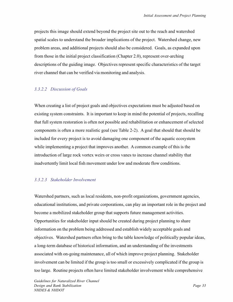
Initial Assessment and Project Planning
Guidelines for Naturalized River ChannelDesign and Bank StabilizationNHDES & NHDOT
Page 33
projects this image should extend beyond the project site out to the reach and watershed
spatial scales to understand the broader implications of the project. Watershed change, new
problem areas, and additional projects should also be considered. Goals, as expanded upon
from those in the initial project classification (Chapter 2.0), represent over-arching
descriptions of the guiding image. Objectives represent specific characteristics of the target
river channel that can be verified via monitoring and analysis.
3.3.2.2 Discussion of Goals
When creating a list of project goals and objectives expectations must be adjusted based on
existing system constraints. It is important to keep in mind the potential of projects, recalling
that full system restoration is often not possible and rehabilitation or enhancement of selected
components is often a more realistic goal (see Table 2-2). A goal that should that should be
included for every project is to avoid damaging one component of the aquatic ecosystem
while implementing a project that improves another. A common example of this is the
introduction of large rock vortex weirs or cross vanes to increase channel stability that
inadvertently limit local fish movement under low and moderate flow conditions.
3.3.2.3 Stakeholder Involvement
Watershed partners, such as local residents, non-profit organizations, government agencies,
educational institutions, and private corporations, can play an important role in the project and
become a mobilized stakeholder group that supports future management activities.
Opportunities for stakeholder input should be created during project planning to share
information on the problem being addressed and establish widely acceptable goals and
objectives. Watershed partners often bring to the table knowledge of politically popular ideas,
a long-term database of historical information, and an understanding of the investments
associated with on-going maintenance, all of which improve project planning. Stakeholder
involvement can be limited if the group is too small or excessively complicated if the group is
too large. Routine projects often have limited stakeholder involvement while comprehensive

Chapter 3.0
Guidelines for Naturalized River ChannelDesign and Bank Stabilization
NHDES & NHDOTPage 34
projects tend to include large stakeholder groups that have multiple opportunities for input
throughout the project.
3.3.3 Design Overview
The alternatives analysis is the main feature of the project design phase. After review of
existing and initial assessment data, a preliminary alternatives matrix is compiled for initial
comparison in terms of how effective each is at meeting project goals and objectives with the
given site constraints (Table 3-1). A project team and greater stakeholder group meeting can
be held to discuss eliminated alternatives and those that are recommended for further
consideration and analysis. This first step of the alternatives analysis rapidly eliminates
unfeasible options allowing for the second step of the analysis to focus on more likely
solutions to the problem. The initial alternatives analysis is a good time to conduct a thought
exercise of identifying ways of eliminating watershed stressors via large-scale management
efforts and river corridor protection initiatives while only considering how best to fix the river.
However unlikely applicable, the holistic thinking promotes discussion of the mechanism of
the stressors, helps to understand the current project within a larger spatial context, and
identifies future management opportunities.
Alternatives that adequately address project goals and objectives, and work within constraints
are confirmed for further investigation by the project team and stakeholders. A complete
alternatives analysis that draws on the most appropriate tools based on the project type –
routine, moderate, or comprehensive – and its goals will lead to an effective final design that
includes multiple checks of findings.
3.3.4 Implementation
Regulatory permitting, funding and site access are three key aspects of implementation that
should be addressed at the beginning of the project. See Chapter 11.0 for a detailed
discussion of these and additional project implementation steps. Permitting requirements and
Initial Assessment and Project Planning
Guidelines for Naturalized River ChannelDesign and Bank StabilizationNHDES & NHDOT
Page 35
Alte
rnat
ive
Incr
ease
se
dim
ent
cont
inui
ty
Impr
ove
chan
nel
stab
ility
Red
uce
brid
ge
scou
r
Impr
ove
aqua
tic
habi
tat
Tow
ards
na
tura
l pr
oces
s
Shor
t or
long
-term
so
lutio
n
Initi
al
rela
tive
cost
est
.C
omm
ents
Rec
.
No
actio
nx
xx
xx
n/a
none
not d
esira
ble,
man
y lo
cal e
rosi
on h
azar
ds, s
yste
m-w
ide
inst
abilit
y
Lim
it se
dim
ent s
uppl
y+
+o
++
long
very
hig
had
dres
s er
osio
n si
tes
thro
ugho
ut ri
ver c
orrid
or
Res
tore
nat
ural
dis
char
ge+
+o
++
long
very
hig
hno
t rev
ersi
ble,
alte
red
hydr
olog
y, d
evel
oped
cor
ridor
, acc
epte
d ris
ks
Lim
it ne
w e
ncro
achm
ents
o+
++
+lo
ngm
ediu
mde
crea
se/p
rohi
bit f
utur
e co
rrid
or c
onfli
cts
Pas
sive
cha
nnel
reco
very
o+
++
+lo
ngm
ediu
msp
ace
to m
eand
er, f
lood
plai
n cr
eatio
n, d
ecre
ases
cor
ridor
con
flict
s
No
actio
nx
xx
xx
n/a
none
not d
esira
ble,
brid
ge p
rone
to s
cour
, mec
hani
sm o
f sed
imen
t bot
tlene
ck
Incr
ease
brid
ge w
idth
+o
+o
+lo
nghi
ghal
low
am
ple
late
ral m
igra
tion,
floo
d be
nch
crea
tion,
incr
ease
saf
ety
Add
ove
rflow
cul
vert
oo
+o
+sh
ort
med
ium
redu
ce h
igh-
flow
bac
kwat
er, f
lood
ben
ch c
reat
ion,
mul
ti-us
e
No
actio
nx
xx
xx
n/a
none
not d
esira
ble,
uns
tabl
e ch
anne
l, in
c. la
tera
l ero
sion
, poo
r hab
itat
Pas
sive
adj
ustm
ent
oo
oo
+lo
nglo
wad
just
men
t lik
ely
with
brid
ge c
hang
e, tr
ack
mon
umen
ted
sect
ions
Adj
ust c
ross
sec
tions
oo
x+
+sh
ort
med
ium
assi
st to
war
ds fl
ood
benc
h cr
eatio
n, c
ompo
und
stab
le c
hann
el
Incr
ease
cha
nnel
slo
pe+
xx
xx
shor
tm
ediu
mop
pose
nat
ural
pro
cess
of d
ecre
asin
g sl
ope
Sta
biliz
e ra
w b
anks
on
site
xo
xx
xsh
ort
med
ium
not p
rese
ntly
wor
king
at s
ite, n
eed
hard
toe,
impr
ove
flow
pat
h
+ G
ood
o M
oder
ate
to fa
irx
Poor
Rec
. = R
ecom
men
ded
furth
er a
naly
sis
Brid
ge A
ltern
ativ
es
Cha
nnel
Alte
rnat
ives
Proj
ect G
oals
and
Obj
ectiv
es Wat
ersh
ed A
ltern
ativ
es
Riv
er C
orrid
or P
rote
ctio
n A
ltern
ativ
es
Tabl
e 3-
1: E
xam
ple
of a
pre
limin
ary
alte
rnat
ives
mat
rix
that
is u
sefu
l for
exp
lora
tion
of p
roje
ct o
ptio
ns, r
ulin
g ou
t alte
rnat
ives
that
are
clea
rly
not f
easi
ble,
and
sel
ectin
g a
sub-
set o
f alte
rnat
ives
that
sho
uld
be c
onsi
dere
d fo
r fu
rthe
r an
alys
is.
Chapter 3.0
Guidelines for Naturalized River ChannelDesign and Bank Stabilization
NHDES & NHDOTPage 36
the amount of available funding directly influence the scope of the project, and site access
alone can impede implementation. Project construction can only take place once the final
design is complete, permits are in hand, and site access is granted. If contractors are needed
to complete the project, those with experience working in rivers and a proven track record of
high quality work should be selected. All field volunteers should be adequately trained and
have a clear understanding of tasks to be accomplished each field day. A member of the
project team should be present to guide as much of the construction as possible to increase the
accuracy and efficiency. Throughout the construction phase, an effort should be made to
minimize harm done to the system so that recovery can take place rapidly. The
implementation phase concludes with post-construction inspection documentation (Chapter
11.0).
3.3.5 Evaluation and Management
All projects include some level of evaluation and management (Chapter 12.0). Ideally, post-
project monitoring can be coupled to a previously established monitoring effort to facilitate
before-after comparisons; however, post-project data collection alone across a range of sites
can be used for effective monitoring as well. Monitoring and evaluation determine if project
objectives are being achieved and if adaptive management (Holling, 1978; OMNR, 2001) is
needed beyond normal operation and maintenance. Limited qualitative evaluation results are
often adequate for routine projects, and results should be communicated to the project team
and watershed stakeholders. Outreach efforts for moderate projects, which typically require
more evaluation when goals include biological and chemical recovery in addition to channel
stability, should extend throughout the region to share outcomes and assist others doing
similar work. The increased investment in comprehensive projects usually requires a more
extensive evaluation. The outcome of comprehensive projects should be shared at the
national level when possible and published in industry, government, or peer-reviewed journals
to advance the science of naturalized river channel design and bank stabilization. Project
reporting will continue to bring together members of government, academia, non-profit
organizations, private companies, and the public to improve current management efforts.
Page 37Guidelines for Naturalized River ChannelDesign and Bank StabilizationNHDES & NHDOT
CHAPTER 4.0: PRE-PROJECT BIOLOGICAL MONITORING
4.1 Introduction
The recommended initial assessment for all river channel design and bank stabilization projects
provides preliminary information on physical habitat, the likely existing and potential
assemblages of organisms, and life-cycle requirements of target fish, macroinvertebrates, and/
or plants. For projects with goals that include improving aquatic habitat and biological
recovery, additional data should be collected to gain a more comprehensive understanding of
the system to guide the ecological aspects of design and establish baseline conditions.
Findings of a biomonitoring program illustrate which expected habitat features are absent so
that they may be incorporated into more naturalized designs. The level of biological
monitoring is synchronized with both the primary project goals and the project classification
as routine, moderate, or comprehensive (Figure 4-1). If recovery of a target species and their
habitat is part of the project goals, the primary function of pre-project monitoring is to gather
the appropriate level of baseline data to compare to post-project effectiveness monitoring
(Chapter 12.0).
Current monitoring protocols suggest that substantial time and funding is needed in order to
confirm biological change following a river management activity; however, resources are often
not available to conduct this level of monitoring. Scaled back monitoring recommendations
are presented here that fit into the typical duration and funding of current naturalized channel
design and bank stabilization projects. The monitoring recommendations will likely expand in
the future as the desire to evaluate project effectiveness through pre- and post-project
monitoring continues to grow.

Chapter 4.0
Guidelines for Naturalized River ChannelDesign and Bank Stabilization
NHDES & NHDOTPage 38
Pro
ject
Typ
e
Mod
erat
eR
outin
eC
ompr
ehen
sive
Pre
-Pro
ject
Bio
logi
cal M
onito
ring
(Cha
pter
4.0
)
Exis
ting
Dat
a?
Dat
aG
athe
ring
yes
no
Biol
ogic
al G
oals
?no
yes
Biom
onito
ring
Prog
ram
Det
erm
ine
Proj
ect E
ffect
iven
ess?
Expa
nded
Bio
mon
itorin
g Pr
ogra
mSi
ngle
Rap
id
Fiel
d A
sses
smen
t
yes
(see
Cha
pter
12.
0 fo
r Po
st-P
roje
ctB
iolo
gica
l Mon
itorin
g R
ecom
men
datio
ns)
One
-tim
e es
timat
ion
of:
1. A
bund
ance
of s
peci
es ta
rget
ed
for r
ecov
ery;
2. P
opul
atio
n tre
nds
over
tim
e of
ta
rget
spe
cies
;3.
Pre
senc
e of
exo
tic a
nd in
vasi
ve
spec
ies;
and
4. A
ppro
xim
ate
ecos
yste
m
com
posi
tion.
For o
ne to
thre
e ye
ars,
ann
ual t
o bi
-an
nual
mea
sure
men
t of:
1. A
bund
ance
of s
peci
es ta
rget
ed fo
r re
cove
ry;
2. A
bund
ance
of k
ey e
xotic
and
in
vasi
ve s
peci
es; a
nd3.
Com
mun
ity in
dice
s of
abu
ndan
ce,
pollu
tion-
tole
ranc
e, a
nd fe
edin
g in
form
atio
n of
key
spe
cies
gro
up.
For t
wo
to fi
ve y
ears
, ann
ual t
o bi
-ann
ual
mea
sure
men
t of:
1. A
bund
ance
of s
peci
es ta
rget
ed fo
r re
cove
ry;
2. A
bund
ance
of k
ey e
xotic
and
inva
sive
sp
ecie
s;3.
Com
mun
ity in
dice
s of
abu
ndan
ce,
pollu
tion-
tole
ranc
e, a
nd fe
edin
g in
form
atio
n of
ke
y sp
ecie
s gr
oup;
and
4. Im
porta
nt b
iolo
gica
l pro
cess
es ta
king
pla
ce
at e
ach
troph
ic le
vel o
f aqu
atic
food
web
.
no
Figu
re 4
-1:
Pre
-pro
ject
bio
logi
cal m
onito
ring
reco
mm
enda
tions
for
rout
ine,
mod
erat
e, a
nd c
ompr
ehen
sive
pro
ject
s.

Pre-Project Biological Monitoring
Guidelines for Naturalized River ChannelDesign and Bank StabilizationNHDES & NHDOT
Page 39
4.2 Biomonitoring
4.2.1 Routine Projects
The recommended biological data for routine projects includes an estimation of:
• The abundance and/or relative abundance of species targeted for recovery;
• Population trends over time of target species;
• The presence of exotic and invasive species; and
• The general overall ecosystem composition.
Routine projects with limited biological goals and objectives usually do not require pre-
project biological monitoring. In this case, existing data and expert knowledge gathered
during the initial assessment (Chapter 3.0) are sufficient to estimate any desired biological
information such as target species population estimates, relative abundances, population
trends, the presence of exotic and invasive species, and the approximate composition of the
ecosystem. This amount of biological data may be sufficient for routine projects having the
main goal of channel stability, but which include secondary biological objectives. If existing
data are limited, a single rapid field assessment is recommended to estimate the biological
information. The rapid field assessment is ideally performed with local experts familiar with
the system and the common regional composition of populations of different river habitats.
Popular methods for choosing sampling locations, timing and collection are available through
the US EPA Rapid Bioassessment Protocols (Barbour et al., 1999) (http://www.epa.gov/
owow/monitoring/rbp/). In addition, state resource managers that conduct biomonitoring
programs may be contacted for guidance (http://www.des.state.nh.us/wmb/Biomonitoring/).
Watershed groups should be contacted to see if data are available from volunteer monitoring.
The rapid field assessment is limited in detail. A single sampling period is common, and
collections should be performed during the month when state biomonitoring programs make

Chapter 4.0
Guidelines for Naturalized River ChannelDesign and Bank Stabilization
NHDES & NHDOTPage 40
most of their collections to facilitate data comparisons and following trends. Avoid
collections during abnormal flow, and in particular following large flood events when
assemblages typically move through disturbance and recovery cycles that differ from typical
conditions. The rapid field assessment should occur at, or immediately downstream of, the
anticipated implementation area. Replicated collections are typically made from a single
habitat type, most typically riffles. The sampling program should focus on the target species
and other important members of the system.
Due to their ubiquitous nature in all stream types, their integrated response to an array of
environmental stressors and the relative ease of collection, macroinvertebrates are useful for
rapid bioassessment. Various texts are available to assist with biomonitoring (Rosenberg and
Resh, 1993; Karr and Chu, 1999) and identification of macroinvertebrates (Pennak, 1978;
McCafferty, 1983; Peckarsky et al., 1990; Merrit and Cummins, 1996). NHDES Coastal
Program has a volunteer biomonitoring program with helpful methods and reports that are
available on the Internet (http://www.des.state.nh.us/Coastal/Resources/). In addition, several
sources of monitoring guidance and basic macroinvertebrate identification guides are available
on the Internet (http://www.epa.gov/bioindicators/html/photos_invertebrates.html and http://
www.umass.edu/tei/mwwp/links.html#fauna). Fish are also popular for single-effort
biomonitoring as they typically are the species targeted for recovery. Data are most often
collected via electro-shocking or snorkeling. Electro-shocking is likely beyond the typical
level of activities associated with a routine project, yet a short snorkel survey is appropriate
where fish habitat is a primary goal to get a better understanding of fish population estimates,
relative abundances, and habitat use at the project site.
4.2.2 Moderate Projects
For moderate projects that do not include biological goals other than to avoid additional harm
to the ecosystem, gathering existing data or a single rapid field assessment is sufficient to
estimate pre-project conditions. A biomonitoring program is recommended for moderate
projects that have biological goals and objectives. The decision to perform biomonitoring is
Pre-Project Biological Monitoring
Guidelines for Naturalized River ChannelDesign and Bank StabilizationNHDES & NHDOT
Page 41
not always straight forward since moderate projects often have multiple objectives including
increasing channel stability and improving aquatic habitat.
Based on their larger size (i.e., reach scale) and common goals of local habitat rehabilitation
or enhancement in addition to increasing channel stability, many moderate projects attempt
recovery of a target species and thus biomonitoring is recommended. For one to three years,
annual to bi-annual measurement of population estimates and/or relative abundances of target
species, abundance of exotic and invasive species, and community indices should be made
before implementation. This program translates to a total range of one to six collections,
which is a function of the available funding and the specific project objectives. The
biomonitoring program suggested for moderate projects focuses on the group that the target
species is a part of (e.g., coldwater fish, riffle-dwelling insects, or mosses).
It is important to contact state officials, members of regional academic institutions, local
watershed groups, or any others that may be biomonitoring in rivers at or near the project site.
Set up a meeting to discuss the sampling locations, frequency, and methods to facilitate data
exchange. Collections for the pre-project biomonitoring program associated with moderate
projects will likely include investigating one or two different habitat types (e.g., riffles and
snags) and be spatially distributed across the project site. Concurrent monitoring is often
performed at additional locations away from the project site to track unchanged controls, a
healthy reference site if available, and a remaining impaired site as a degraded benchmark.
An example of a biomonitoring program that is common for moderate projects is the
replicated monitoring of trout before (and after) project implementation via electro-fishing.
State and federal resource managers are typically involved in this biological monitoring given
the specialized equipment and training requirements. Existing data and methods are often
available via the Internet. For example, one can obtain information on fish (http://
www.des.state.nh.us/wmb/Biomonitoring/fish_assess) and macroinvertebrate (http://
www.des.state.nh.us/wmb/Biomonitoring/inverts) community assessment in New Hampshire
from the website of the New Hampshire Biomonitoring Program.
Chapter 4.0
Guidelines for Naturalized River ChannelDesign and Bank Stabilization
NHDES & NHDOTPage 42
4.2.3 Comprehensive Projects
Comprehensive projects are large in size, often spanning multiple reaches, and thus their
impact on a river channel and biology is great. For this reason, and because projects of this
size almost always include habitat and biological recovery goals, biomonitoring is
recommended. The biomonitoring program described above for moderate projects is ample
where project effectiveness does not need to be determined; however, an expanded
biomonitoring program is needed for effectiveness monitoring.
For two to five years, annual to bi-annual measurement of population estimates and/or relative
abundances of target species, abundance of exotic and invasive species, and community
indices should be made before implementation. This program translates to a total range of
two to ten collections, which is a function of the available funding and the specific project
objectives. The biomonitoring program suggested for comprehensive projects can focus on
the group that the target species is a part of, but can also include other groups that likely
influence the target species such as its main predator and prey. The expanded biomonitoring
program includes investigating multiple habitats, spatial distribution across the project site,
and concurrent monitoring at a range of control, reference, and impaired sites.
When system restoration through returning important processes that form high quality habitat
is a goal of a comprehensive project, an effort should be made to identify the key processes
and interactions at each level of the aquatic food web. Does the system primarily rely on
external inputs to drive the base of the food web (i.e., heterotrophic) or does most of the food
come from instream plant production (autotrophic)? What are the primary pathways of
energy through the aquatic food web, and where do potential bottlenecks exist? Biological
processes such as photosynthesis, respiration, nutrient processing, and the breakdown of
organic matter should be considered. If post-project monitoring is continued for a long
enough time (Chapter 12.0), the expanded biomonitoring program should allow for the
determination of project effectiveness.
Pre-Project Biological Monitoring
Guidelines for Naturalized River ChannelDesign and Bank StabilizationNHDES & NHDOT
Page 43
4.3 Physical Habitat Assessment
Almost all naturalized river channel design and bank stabilization projects influence physical
habitat and thus a pre-project assessment should be made. Important habitat parameters
include:
• Large and small organic matter;
• Bed substrate;
• Scour and deposition features;
• Channel morphology;
• In- and near-channel hydrology;
• Longitudinal and lateral connectivity;
• River banks; and
• Riparian areas.
The EPA habitat assessment mentioned in the previous chapter (Section 3.2.2.5) is commonly
used for a quick assessment. The Vermont Agency of Natural Resources is presently
developing a new rapid habitat assessment (RHA) that establishes indicator variables of key
habitat-forming physical processes and components essential for life-cycle requirements
(VTANR, 2005). Once complete, the RHA will be available for different channel types and
will be a quick and thorough habitat assessment tool. The Vermont Geomorphic Assessment
Protocols, which include both a rapid geomorphic assessment and the RHA, is available on
the Internet (http://www.anr.state.vt.us/dec/waterq/rivers).
For routine projects, where physical change is limited to a small part of a river channel or
bank, a brief qualitative description of the listed parameters and how they may change is
ample to track physical habitat. For moderate and comprehensive projects that cover larger
areas and often include biological goals and objectives, a more thorough investigation of the
physical habitat parameters is recommended. The following observations and measurements
should be made during site walks and field sketches of habitat features, most of which are

Chapter 4.0
Guidelines for Naturalized River ChannelDesign and Bank Stabilization
NHDES & NHDOTPage 44
collected during the initial data assessment or readily available as data are collected to inform
the design. Estimate:
• The abundance of large woody debris (LWD);
• The percentages of boulders, cobbles, gravels, and sands in approximately 10 square
feet (1 square meter), as well as the degree to which the bed follows the expected
riffle-run-pool-glide, step-pool, or other pattern as one moves down a river reach;
• The abundance, spacing, and quality of the main scour and depositional features
(riffles, steps, pools) associated with the given channel type;
• Channel morphology variables at monumented cross sections as determined during
data collection for the appropriate level of design;
• In-channel hydrology characteristics, and the presence of riparian wetlands;
• The degree of longitudinal connectivity (abundance of blockages such as dams,
culverts and bedrock outcrops) and floodplain connectivity (entrenchment ratio);
• The abundance of vegetative cover, overhanging vegetation, and canopy cover, the
degree of erosion on the river banks; and
• The abundance of vegetative cover and dominant land use in the riparian corridor.
Page 45Guidelines for Naturalized River ChannelDesign and Bank StabilizationNHDES & NHDOT
CHAPTER 5.0: PRE-PROJECT CHEMICAL MONITORING
5.1 Introduction
A review of local and regional water and sediment quality data gathered during the initial
assessment for all naturalized river channel design and bank stabilization projects offers
information on background chemistry and potential chemical threats. For projects with water
quality improvement goals, additional chemical data are needed to determine baseline
conditions for comparison to post-project monitoring (Chapter 12.0). The amount of
chemical monitoring is not only a function of project goals, but also project classification as
routine, moderate, or comprehensive (Figure 5-1).
5.2 Chemical Monitoring
5.2.1 Routine Projects
The recommended chemical data for routine projects include an estimation of:
• Basic water quality parameters (temperature, pH, conductivity, dissolved oxygen, and
turbidity) at several recent points in time;
• Watershed water quality and trends; and
• Major geologic and anthropogenic water quality signals in the watershed.
Routine projects with limited water quality goals and objectives usually do not require pre-
project chemical monitoring. In this case, existing data and expert knowledge gathered during
the initial assessment (Chapter 3.0) are sufficient to estimate the desired chemical information.
This amount of chemical data may be sufficient for routine projects having the main goal of
channel stability, but which include secondary water quality objectives. If existing data are
Chapter 5.0
Guidelines for Naturalized River ChannelDesign and Bank Stabilization
NHDES & NHDOTPage 46
Pro
ject
Typ
e
Mod
erat
eR
outin
eC
ompr
ehen
sive
Pre
-Pro
ject
Che
mic
al M
onito
ring
(Cha
pter
5.0
)
Exis
ting
Dat
a?
Dat
aG
athe
ring
yes
no
Wat
er Q
ualit
y G
oals
?no
yes
Che
mic
al M
onito
ring
Pro
gram
Det
erm
ine
Proj
ect E
ffect
iven
ess?
Expa
nded
Che
mic
al
Mon
itorin
g P
rogr
amS
ingl
e R
apid
Fi
eld
Ass
essm
ent
yes
(see
Cha
pter
12.
0 fo
r P
ost-P
roje
ctC
hem
ical
Mon
itorin
g R
ecom
men
datio
ns)
no
One
-tim
e es
timat
ion
of:
1. B
asic
wat
er q
ualit
y pa
ram
eter
s (te
mpe
ratu
re, p
H, c
ondu
ctiv
ity, d
isso
lved
ox
ygen
, and
turb
idity
) at s
ever
al re
cent
po
ints
in ti
me
at p
roje
ct s
ite;
2. W
ater
shed
wat
er q
ualit
y tre
nds;
and
3. M
ajor
geo
logi
c an
d an
thro
poge
nic
wat
ersh
ed w
ater
qua
lity
sign
als.
For o
ne to
thre
e ye
ars,
ann
ual t
o bi
-an
nual
mea
sure
men
t of:
1. B
asic
wat
er q
ualit
y pa
ram
eter
s,
pref
erab
ly w
ith p
erio
ds o
f con
tinuo
us
mon
itorin
g;2.
Prio
rity
wat
er q
ualit
y po
lluta
nts;
3. P
riorit
y se
dim
ent q
ualit
y po
lluta
nts;
an
d4.
Nut
rient
s.
For o
neto
five
yea
rs, a
nnua
l to
bi-
annu
al b
asef
low
and
eve
nt fl
ow
mea
sure
men
tsof
:1.
Bas
ic w
ater
qua
lity
para
met
ers,
with
pe
riods
of c
ontin
uous
mon
itorin
g;2.
Prio
rity
wat
er q
ualit
y po
lluta
nts;
3. P
riorit
y se
dim
ent q
ualit
y po
lluta
nts;
an
d4.
Nut
rient
s.
Figu
re 5
-1:
Pre
-pro
ject
che
mic
al m
onito
ring
reco
mm
enda
tions
for
rout
ine,
mod
erat
e, a
nd c
ompr
ehen
sive
pro
ject
s.
Pre-Project Chemical Monitoring
Guidelines for Naturalized River ChannelDesign and Bank StabilizationNHDES & NHDOT
Page 47
limited, a single rapid field assessment is recommended to estimate the chemical information.
The rapid field assessment is ideally performed with local experts familiar with the system and
water quality measurement and interpretation.
The one-time rapid field assessment will consist of making measurement of basic water quality
parameters using portable field probes during baseflow conditions. Standard methods
(Clesceri et al., 1998) should be referred to for proper measurement techniques. The New
Hampshire Volunteer River Assessment Program (VRAP), which offers groups technical
support and equipment loaners to conduct water quality monitoring, has many useful
protocols and reports that are accessible on the Internet (http://www.des.state.nh.us/wmb/
vrap/). In addition, state resource managers that regularly conduct water quality monitoring
programs may be contacted for guidance (http://www.des.state.nh.us/WMB/biomonitoring/
chem). Watershed groups should be contacted to see if data are available from volunteer
monitoring programs. Existing data and reporting in the watershed and region should be used
to estimate water quality trends and signals.
5.2.2 Moderate Projects
For moderate projects that do not include water quality goals other than to avoid additional
harm to the ecosystem, gathering existing data or a single rapid field assessment are sufficient
to estimate pre-project conditions. A chemical monitoring program is recommended for
moderate projects that have water quality goals and objectives. For example, a chemical
monitoring program would be appropriate for a moderate project where channel and bank
stabilization are performed to ultimately improve water clarity. In this case, turbidity would
be the priority water quality parameter monitored.
Chapter 5.0
Guidelines for Naturalized River ChannelDesign and Bank Stabilization
NHDES & NHDOTPage 48
For moderate projects with water quality goals and objectives, the recommended chemical
monitoring program includes measurement of:
• Basic water quality parameters, preferably with some period of continuous monitoring;
• Priority water quality pollutants;
• Priority sediment quality pollutants (where applicable); and
• Nutrients.
Annual to bi-annul data collection is recommended for one to three years, for a total range of
one to six collections. The number of data collections is a function of the water quality goals
and the available funding. Monitoring should be performed during the appropriate flow
condition for the parameter of interest. For example, if dissolved oxygen is the issue than
monitoring should take place during low flows, while bacteria or nutrient issues may require
monitoring after a rainfall when the channel is conveying stormwater. The best method of
investigating most basic water quality parameters such as temperature, pH, conductivity,
dissolved oxygen and turbidity is by deploying continuous monitoring data-loggers to track
the changes over time. Whenever possible, deploy data-loggers over the course of several
weeks as they are an economical and practical way to gather good data over large project
areas. Refer to standard methods (Clesceri et al., 1998) for proper sample collection,
handling, and analysis.
Priority water and sediment quality pollutants can be identified from existing data or inferred
from the project problem identification and the land use in the river corridor. Include
sediment analysis in the monitoring program for moderate projects in watersheds where trace
metal contaminants or excessive nutrients could be present. Sediment quality monitoring is
important to ensure habitat for bottom-dwelling, or benthic, species is not impaired by local
hotspots of deposited pollution-laden sediment.
The concentration of nutrients, and in particular phosphorus in fresh water and nitrogen in salt
water, is a primary factor that determines the abundance of aquatic plants, which in turn
Pre-Project Chemical Monitoring
Guidelines for Naturalized River ChannelDesign and Bank StabilizationNHDES & NHDOT
Page 49
regulate dissolved oxygen levels and pH via photosynthesis and respiration. Swings in both
dissolved oxygen and pH associated with the daily, or diel, cycling between photosynthesis
and respiration are factors that can limit aquatic habitat. Data-loggers are very useful for
tracking diel cycling.
It is important to contact state officials, members of regional academic institutions, local
watershed groups, or any others that might be participating in on-going chemical monitoring
programs at rivers near the project site. Set up a meeting to discuss the sampling locations,
frequency, and methods to facilitate data exchange. Several programs within the NHDES
Watershed Management Bureau (http://www.des.state.nh.us/wmb/) such as River
Management and Protection, Biomonitoring, and VRAP should be contacted to discuss water
quality monitoring. New Hampshire sampling data and locations can be found at the NHDES
OneStop (http://www.des.state.nh.us/OneStop).
For moderate projects, concurrent monitoring is recommended at a control site away from the
project site.
5.2.3 Comprehensive Projects
Chemical monitoring is recommended for comprehensive projects because they are large in
size, often spanning multiple reaches, and thus their potential influence on water quality is
considerable. The chemical monitoring program described above for moderate projects is
ample where project effectiveness does not need to be determined; however, an expanded
chemical monitoring program is needed for effectiveness monitoring.
Chapter 5.0
Guidelines for Naturalized River ChannelDesign and Bank Stabilization
NHDES & NHDOTPage 50
For comprehensive projects where determining project effectiveness is desired, the
recommended chemical monitoring program includes measurement of:
• Basic water quality parameters, preferably with periods of continuous monitoring;
• Priority water quality pollutants;
• Priority sediment quality pollutants (where applicable); and
• Nutrients.
Note that these are the same data collected for moderate projects with water quality goals.
The difference here is that the more frequent sampling is recommended to allow for
determination of project effectiveness. Annual to bi-annul data collection is recommended for
one to five years, where a single collection consists of both a baseflow and event flow
observation, for a total range of two to twenty collections. The number of data collections is
a function of the water quality goals and available funding. Again, the flow condition and
duration of sampling should be set based on the water quality parameters to be measured.
An expanded chemical monitoring program often includes concurrent monitoring at a control,
reference, or impaired sites, as well as monitoring of other mainstem rivers in the watershed.
If post project monitoring is continued for a long enough time (Chapter 12.0), the expanded
chemical monitoring program should allow for the determination of project effectiveness in
terms of changes to water quality.
Page 51Guidelines for Naturalized River ChannelDesign and Bank StabilizationNHDES & NHDOT
CHAPTER 6.0: RIVER CHANNEL STRESSORS AND RESPONSES
6.1 Introduction
River channels respond to stressors based on their vulnerability to adjustment (i.e., the level of
force that the channel bed and banks can withstand before excessive adjustment takes place).
Stressors may originate from both natural and human causes. Natural stressors include
geologic, biologic, and meteorological conditions that are largely independent of human
activity. Common stressors caused by humans include activities associated with
channelization and hydrologic alteration. The response to channel stressors includes changes
in conveyance of water and sediment, channel degradation (i.e., down-cutting) and
aggradation, and changes in rates of erosion and deposition. Accurate identification of
channel stressors and responses will guide the establishment of design alternatives.
6.2 Vulnerability
An important part of river management is being able to identify potential problems before they
occur and to connect land use activities with channel changes.
River channels vary from being very resilient and stable to being vulnerable to internal and
external forces that create channel distress and adjustment. Stable channels, such as those
bounded by bedrock or boulders, may be virtually static and highly resistant to change.
Alluvial channels, including those that are high-gradient with coarse bed material and low-
gradient meandering with sand beds, are very sensitive to changes. Physically vulnerable
channels can lead to widespread channel adjustment that can threaten river ecology, nearby
infrastructure, and social values (Table 6-1).
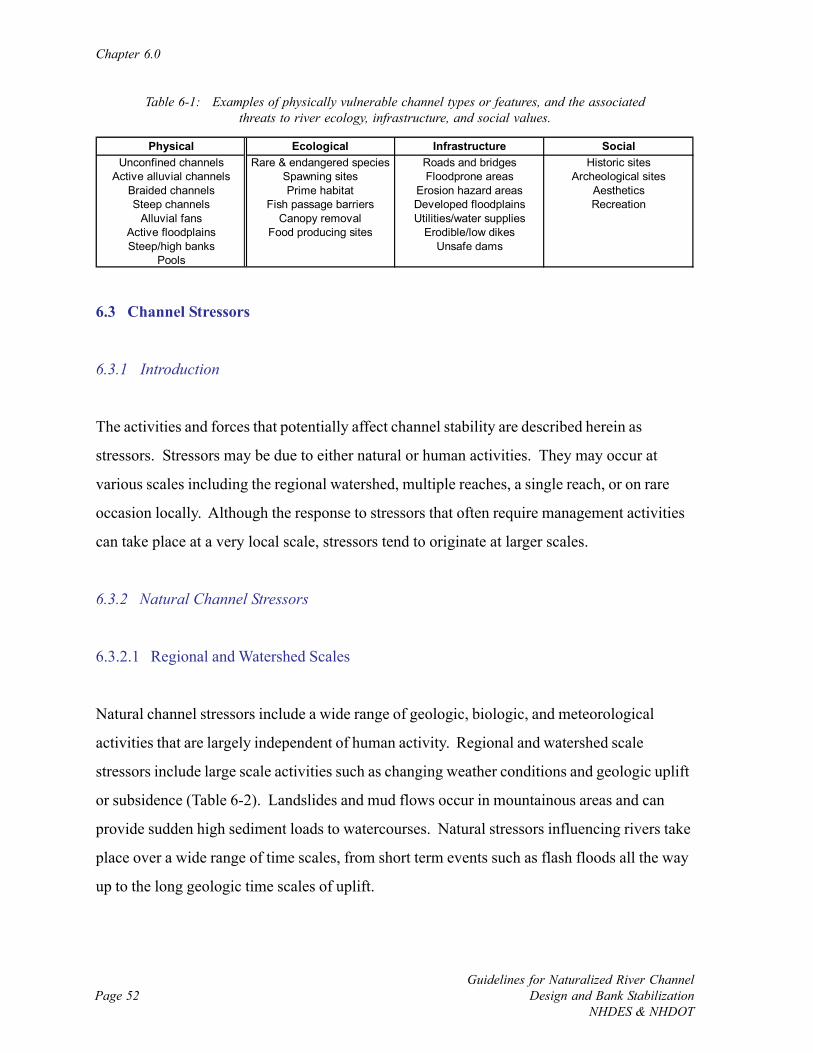
Chapter 6.0
Guidelines for Naturalized River ChannelDesign and Bank Stabilization
NHDES & NHDOTPage 52
Physical Ecological Infrastructure SocialUnconfined channels Rare & endangered species Roads and bridges Historic sites
Active alluvial channels Spawning sites Floodprone areas Archeological sitesBraided channels Prime habitat Erosion hazard areas AestheticsSteep channels Fish passage barriers Developed floodplains Recreation
Alluvial fans Canopy removal Utilities/water suppliesActive floodplains Food producing sites Erodible/low dikesSteep/high banks Unsafe dams
Pools
Table 6-1: Examples of physically vulnerable channel types or features, and the associatedthreats to river ecology, infrastructure, and social values.
6.3 Channel Stressors
6.3.1 Introduction
The activities and forces that potentially affect channel stability are described herein as
stressors. Stressors may be due to either natural or human activities. They may occur at
various scales including the regional watershed, multiple reaches, a single reach, or on rare
occasion locally. Although the response to stressors that often require management activities
can take place at a very local scale, stressors tend to originate at larger scales.
6.3.2 Natural Channel Stressors
6.3.2.1 Regional and Watershed Scales
Natural channel stressors include a wide range of geologic, biologic, and meteorological
activities that are largely independent of human activity. Regional and watershed scale
stressors include large scale activities such as changing weather conditions and geologic uplift
or subsidence (Table 6-2). Landslides and mud flows occur in mountainous areas and can
provide sudden high sediment loads to watercourses. Natural stressors influencing rivers take
place over a wide range of time scales, from short term events such as flash floods all the way
up to the long geologic time scales of uplift.
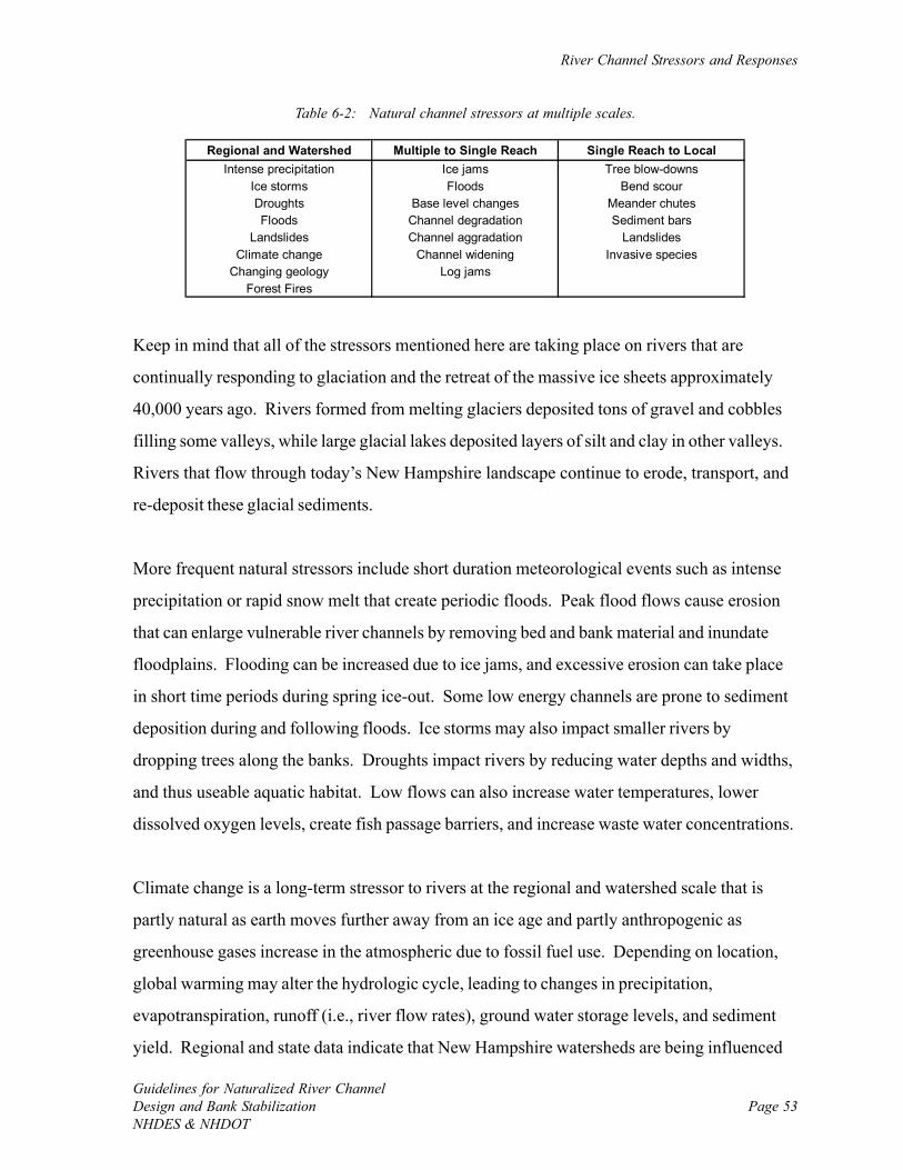
River Channel Stressors and Responses
Guidelines for Naturalized River ChannelDesign and Bank StabilizationNHDES & NHDOT
Page 53
Regional and Watershed Multiple to Single Reach Single Reach to LocalIntense precipitation Ice jams Tree blow-downs
Ice storms Floods Bend scourDroughts Base level changes Meander chutesFloods Channel degradation Sediment bars
Landslides Channel aggradation LandslidesClimate change Channel widening Invasive species
Changing geology Log jamsForest Fires
Table 6-2: Natural channel stressors at multiple scales.
Keep in mind that all of the stressors mentioned here are taking place on rivers that are
continually responding to glaciation and the retreat of the massive ice sheets approximately
40,000 years ago. Rivers formed from melting glaciers deposited tons of gravel and cobbles
filling some valleys, while large glacial lakes deposited layers of silt and clay in other valleys.
Rivers that flow through today’s New Hampshire landscape continue to erode, transport, and
re-deposit these glacial sediments.
More frequent natural stressors include short duration meteorological events such as intense
precipitation or rapid snow melt that create periodic floods. Peak flood flows cause erosion
that can enlarge vulnerable river channels by removing bed and bank material and inundate
floodplains. Flooding can be increased due to ice jams, and excessive erosion can take place
in short time periods during spring ice-out. Some low energy channels are prone to sediment
deposition during and following floods. Ice storms may also impact smaller rivers by
dropping trees along the banks. Droughts impact rivers by reducing water depths and widths,
and thus useable aquatic habitat. Low flows can also increase water temperatures, lower
dissolved oxygen levels, create fish passage barriers, and increase waste water concentrations.
Climate change is a long-term stressor to rivers at the regional and watershed scale that is
partly natural as earth moves further away from an ice age and partly anthropogenic as
greenhouse gases increase in the atmospheric due to fossil fuel use. Depending on location,
global warming may alter the hydrologic cycle, leading to changes in precipitation,
evapotranspiration, runoff (i.e., river flow rates), ground water storage levels, and sediment
yield. Regional and state data indicate that New Hampshire watersheds are being influenced
Chapter 6.0
Guidelines for Naturalized River ChannelDesign and Bank Stabilization
NHDES & NHDOTPage 54
by climate change (Rock, 2006). New Hampshire’s climate displays considerable variability
from year-to-year, with a trend of warming winter temperatures over the past 4 years (Wake
et al., 2006). Total annual precipitation in New England has increased 3.3 inches between
1899 and 2000, with an apparent rise in frequency of more intense storm events (Markham
and Wake, 2005). Larger floods, particularly in channels that are disconnected from their
historic floodplains, would likely reduce channel stability. Higher flows generally lead to
wider channels, which increases threats and management obligations in river corridors. As
with the influence of deglaciation, the changes in the regional weather patterns associated with
global climate change will have a long-term and continuous effect on New Hampshire rivers.
Coastal areas of New England already have seen increases in mean annual precipitation, with
larger and more intense storms occurring more frequently. Information from the National
Oceanic and Atmospheric Administration (NOAA) indicates that sea level is rising at an
accelerated rate. Coastal rivers thus have an increasing base water level at their outlets that
raises tide levels and upstream water surface elevations. In addition, habitats can change if the
salinity wedge moves inland.
6.3.2.2 Multiple to Single Reach Scales
Natural channel stressors also occur at scales of multiple to single reaches. These stressors
include activities such as seasonal ice jams, localized flash floods such as those produced by
thunderstorms, and local changes in sediment loads such as from landslides or forest fires.
Other intermediate scale stressors include gradual natural movement of sediment through
fluvial systems that lead to localized channel degradation, aggradation, or general widening.
Multiple to single reach scale stressors tend to be short duration events that occur annually or
more often.
River Channel Stressors and Responses
Guidelines for Naturalized River ChannelDesign and Bank StabilizationNHDES & NHDOT
Page 55
6.3.2.3 Single Reach to Local Scales
Small scale natural stressors affect a limited area such as the impacts of an uprooted tree
across a small channel or a local landslide. Other local stressors include local erosion and
deposition, meander chute cut-offs, and the formation of sediment bars. More often than not,
small scale stressors ultimately originate at larger scales.
6.3.3 Stressors Caused by Humans
6.3.3.1 Introduction
There are many human activities that may alter river processes, ranging from watershed-wide
changes in hydrology or sediment loads to direct local modification of river channels (Table 6-
3). River channels in New England are presently responding to reforestation during the 20th
century following widespread deforestation in the 19th century for timber and farmland
creation. In addition, historic channel straightening took place in the late 19th/early 20th
centuries for log drives as on the upper Connecticut River. Historical channelization has taken
place to reduce local flooding and lateral movement to allow for more development in the
floodplain. Changes to the landscape such as logging, farming, and urbanization have created
stressors to the river by altering watershed hydrology. Land development in the river corridor
can lead to excessive physical adjustment of the river channel that reduces water quality,
degrades aquatic habitat, and creates long-term management obligations to protect
infrastructure.
6.3.3.2 Channelization (straightening, armoring, filling, widening, deepening, clearing)
Channelization includes the collective actions of straightening, armoring, filling, widening,
deepening, clearing and otherwise altering natural rivers to increase flow capacity and reduce
flooding. Other reasons for channelization include protection of encroachments in the
floodplain (Figure 6-1), filling of wetlands or part of the channel to reclaim land (Figure 6-2),
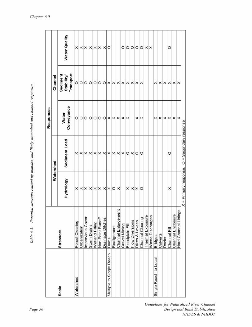
Chapter 6.0
Guidelines for Naturalized River ChannelDesign and Bank Stabilization
NHDES & NHDOTPage 56
Hyd
rolo
gyS
edim
ent L
oad
Wat
er
Con
veya
nce
Sed
imen
t S
tabi
lity/
Tr
ansp
ort
Wat
er Q
ualit
y
Wat
ersh
edFo
rest
Cle
arin
gX
XO
OX
Urb
aniz
atio
nX
XO
OX
Impe
rvio
us C
over
XX
OO
XS
torm
Dra
ins
XX
OO
XW
etla
nd F
illin
gX
XO
OX
Non
-Poi
nt R
unof
fX
XO
OX
Dra
inag
e D
itche
sX
XO
OX
Mul
tiple
to S
ingl
e R
each
Dam
sX
XX
XO
Rea
lignm
ent
OX
XX
Cha
nnel
Enl
arge
men
tX
XX
XG
rave
l Min
ing
XX
XO
Floo
dpla
in F
illX
OX
XO
Flow
Div
ersi
ons
XX
XO
Dik
es &
Lev
ees
XO
XX
OC
hann
el C
lear
ing
OO
XX
OT
herm
al E
xpos
ure
XW
aste
Dis
char
ges
XS
ingl
e R
each
to L
ocal
Brid
ges
XX
Cul
verts
XX
Doc
ksX
XC
hann
el F
illX
OX
XO
Cha
nnel
Enc
losu
reX
XH
ard
Cha
nnel
Lin
ings
XX
X =
Prim
ary
resp
onse
, O
= S
econ
dary
resp
onse
Res
pons
esW
ater
shed
Cha
nnel
Sca
leS
tres
sors
Tabl
e 6-
3:
Pote
ntia
l stre
ssor
s ca
used
by
hum
ans,
and
likel
y w
ater
shed
and
cha
nnel
resp
onse
s.
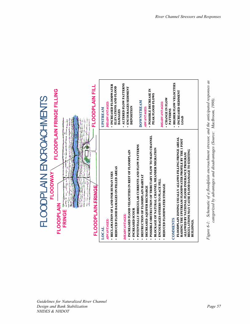
River Channel Stressors and Responses
Guidelines for Naturalized River ChannelDesign and Bank StabilizationNHDES & NHDOT
Page 57
FLOO
DPLA
IN E
NCRO
ACHM
ENTS
UPS
TR
EAM
DISADVANTAGES:
•IN
CR
EASE
D F
LO
OD
WA
TE
R
EL
EVA
TIO
NS
AN
D F
LO
OD
D
AM
AG
ES•
ALT
ER
ED F
LOW
PA
TTE
RN
S•
EN
CO
UR
AG
ES
SED
IME
NT
DEP
OSI
TIO
N
DO
WN
STR
EA
MADVANTAGES:
•PO
SSIB
LE
DE
CR
EA
SE IN
PE
AK
FL
OO
D F
LO
WS
DISADVANTAGES:
•C
HA
NG
E IN
FLO
W
PAT
TER
NS
•H
IGH
ER
FL
OW
VE
LOC
ITIE
S•
INC
REA
SED
SED
IME
NT
L
OA
D
LO
CA
LADVANTAGES:
•R
ECL
AM
ATI
ON
OF
LA
ND
FO
R H
UM
AN
USE
S•
RED
UC
ED
FL
OO
D D
AM
AG
ES O
N F
ILL
ED
AR
EA
S
DISADVANTAGES:
•IN
CR
EASE
D F
LO
OD
VE
LO
CIT
IES
IN R
EST
OF
FLO
OD
PLA
IN•
INC
REA
SED
SC
OU
R•
POT
ENTI
AL
LY IR
RE
GU
LA
R C
UR
REN
TS A
ND
FLO
W P
ATT
ER
NS
•D
EST
RU
CTI
ON
OF
FLO
OD
PLA
IN H
AB
ITA
T•
DEC
REA
SED
AQ
UIF
ER
REC
HA
RG
E•
POSS
IBL
E O
BST
RU
CT
ION
OF
TR
IBU
TA
RY
FLO
W T
O M
AIN
CH
AN
NE
L•
BLO
CK
AG
E O
F N
AT
UR
AL
CH
AN
NE
L M
EA
ND
ER
MIG
RA
TIO
N•
ENC
OU
RA
GE
S O
TH
ER
S T
O P
LA
CE
FIL
L•
RED
UC
ED
FL
OO
DW
AT
ER
ST
OR
AG
E
CO
MM
ENT
SFL
OO
DPL
AIN
ZO
NIN
G U
SUA
LLY
ALL
OW
S FI
LL
ING
FR
ING
E A
REA
S.
RA
ISIN
G T
HE
UPS
TR
EA
M F
LO
OD
WA
TER
PR
OFI
LE B
Y T
HE
1 F
OO
T A
LLO
WE
D B
Y N
AT
ION
AL
FLO
OD
INSU
RA
NC
E PR
OG
RA
M
REG
ULA
TIO
NS
MA
Y C
AU
SE F
LO
OD
DA
MA
GE
TO E
XIS
TIN
G
BU
ILD
ING
S.
UPS
TR
EAM
DISADVANTAGES:
•IN
CR
EASE
D F
LO
OD
WA
TE
R
EL
EVA
TIO
NS
AN
D F
LO
OD
D
AM
AG
ES•
ALT
ER
ED F
LOW
PA
TTE
RN
S•
EN
CO
UR
AG
ES
SED
IME
NT
DEP
OSI
TIO
N
DO
WN
STR
EA
MADVANTAGES:
•PO
SSIB
LE
DE
CR
EA
SE IN
PE
AK
FL
OO
D F
LO
WS
DISADVANTAGES:
•C
HA
NG
E IN
FLO
W
PAT
TER
NS
•H
IGH
ER
FL
OW
VE
LOC
ITIE
S•
INC
REA
SED
SED
IME
NT
L
OA
D
LO
CA
LADVANTAGES:
•R
ECL
AM
ATI
ON
OF
LA
ND
FO
R H
UM
AN
USE
S•
RED
UC
ED
FL
OO
D D
AM
AG
ES O
N F
ILL
ED
AR
EA
S
DISADVANTAGES:
•IN
CR
EASE
D F
LO
OD
VE
LO
CIT
IES
IN R
EST
OF
FLO
OD
PLA
IN•
INC
REA
SED
SC
OU
R•
POT
ENTI
AL
LY IR
RE
GU
LA
R C
UR
REN
TS A
ND
FLO
W P
ATT
ER
NS
•D
EST
RU
CTI
ON
OF
FLO
OD
PLA
IN H
AB
ITA
T•
DEC
REA
SED
AQ
UIF
ER
REC
HA
RG
E•
POSS
IBL
E O
BST
RU
CT
ION
OF
TR
IBU
TA
RY
FLO
W T
O M
AIN
CH
AN
NE
L•
BLO
CK
AG
E O
F N
AT
UR
AL
CH
AN
NE
L M
EA
ND
ER
MIG
RA
TIO
N•
ENC
OU
RA
GE
S O
TH
ER
S T
O P
LA
CE
FIL
L•
RED
UC
ED
FL
OO
DW
AT
ER
ST
OR
AG
E
CO
MM
ENT
SFL
OO
DPL
AIN
ZO
NIN
G U
SUA
LLY
ALL
OW
S FI
LL
ING
FR
ING
E A
REA
S.
RA
ISIN
G T
HE
UPS
TR
EA
M F
LO
OD
WA
TER
PR
OFI
LE B
Y T
HE
1 F
OO
T A
LLO
WE
D B
Y N
AT
ION
AL
FLO
OD
INSU
RA
NC
E PR
OG
RA
M
REG
ULA
TIO
NS
MA
Y C
AU
SE F
LO
OD
DA
MA
GE
TO E
XIS
TIN
G
BU
ILD
ING
S.
FLO
OD
PLA
INFR
ING
E
FLO
OD
WA
YFL
OO
DPL
AIN
FR
ING
E FI
LLIN
G
FLO
OD
PLA
IN F
ILL
FLO
OD
PLA
IN F
RIN
GE
Figu
re 6
-1:
Sch
emat
ic o
f a fl
oodp
lain
enc
roac
hmen
t stre
ssor
, and
the
antic
ipat
ed re
spon
ses
asca
tego
rize
d by
adv
anta
ges
and
disa
dvan
tage
s (S
ourc
e: M
acBr
oom
, 199
8).
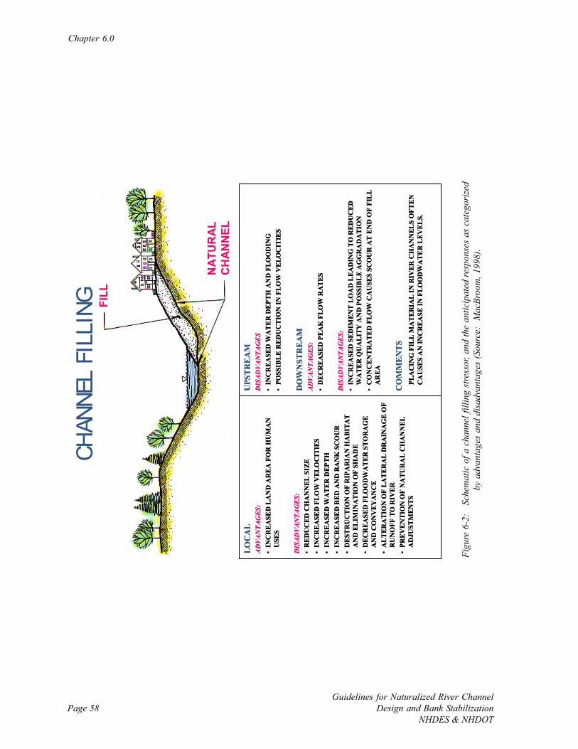
Chapter 6.0
Guidelines for Naturalized River ChannelDesign and Bank Stabilization
NHDES & NHDOTPage 58
CHAN
NEL
FILL
ING
UPS
TRE
AM
DISADVANTAGES
•IN
CR
EA
SED
WA
TE
R D
EPT
H A
ND
FLO
OD
ING
•PO
SSIB
LE R
EDU
CT
ION
IN F
LOW
VE
LOC
ITIE
S
DO
WN
STR
EAM
ADVANTAGES:
•D
EC
RE
ASE
D P
EAK
FL
OW
RA
TES
DISADVANTAGES:
•IN
CR
EA
SED
SE
DIM
ENT
LOA
D L
EAD
ING
TO
RED
UC
ED
WA
TER
QU
AL
ITY
AN
D P
OSS
IBLE
AG
GR
AD
AT
ION
•C
ON
CEN
TRA
TE
D F
LO
W C
AU
SES
SCO
UR
AT
EN
D O
F FI
LL
AR
EA
CO
MM
EN
TSPL
AC
ING
FIL
L M
AT
ER
IAL
IN R
IVER
CH
AN
NEL
S O
FTEN
C
AU
SES
AN
INC
RE
ASE
IN F
LOO
DW
AT
ER
LE
VE
LS.
LOC
AL
ADVANTAGES:
•IN
CR
EA
SED
LA
ND
AR
EA
FO
R H
UM
AN
U
SES
DISADVANTAGES:
•R
ED
UC
ED C
HA
NN
EL S
IZE
•IN
CR
EA
SED
FL
OW
VEL
OC
ITIE
S•
INC
RE
ASE
D W
AT
ER
DE
PTH
•IN
CR
EA
SED
BED
AN
D B
AN
K S
CO
UR
•D
EST
RU
CT
ION
OF
RIP
AR
IAN
HA
BIT
AT
AN
D E
LIM
INA
TIO
N O
F SH
AD
E•
DE
CR
EA
SED
FL
OO
DW
AT
ER S
TO
RA
GE
A
ND
CO
NV
EY
AN
CE
•A
LT
ERA
TIO
N O
F LA
TE
RA
L D
RA
INA
GE
OF
RU
NO
FF T
O R
IVER
•PR
EV
EN
TIO
N O
F N
AT
UR
AL
CH
AN
NE
L
AD
JUST
MEN
TS
FILL
NAT
UR
AL
CH
ANN
EL
Figu
re 6
-2:
Sch
emat
ic o
f a c
hann
el fi
lling
stre
ssor
, and
the
antic
ipat
ed re
spon
ses
as c
ateg
oriz
edby
adv
anta
ges
and
disa
dvan
tage
s (S
ourc
e: M
acBr
oom
, 199
8).
River Channel Stressors and Responses
Guidelines for Naturalized River ChannelDesign and Bank StabilizationNHDES & NHDOT
Page 59
and navigation improvement. Channelization can cause severe disruption of local river
morphology and ecology. In addition, channelization and the resulting increased sediment
transport can have strong implications for channel behavior downstream when mobilized
sediment is deposited.
Straightening channels (Figure 6-3) reduces their length but not the vertical drop; hence the
channel slope is increased. This leads to higher flow velocities and greater sediment transport.
The channel will erode sediment and degrade unless artificially stabilized or an additional
sediment load is supplied. Changing the channel slope can induce a change in channel pattern.
Degradation is common on steepened channels, and can progress upstream and into
tributaries. The material eroded may form sediment deposits downstream of the straightened
reach.
Armoring channel banks and bottom via rock riprap (Figure 6-4), rigid lining (Figure 6-5),
walls, or other hard materials is performed to prevent a river channel from moving. Bank
armoring prevents side-to-side movement, and is typically applied to protect infrastructure
near the rive channel by changing local erosion and deposition patterns. Armoring the channel
bed stops vertical movement, and is often used to prevent severe erosion or match grades near
infrastructure such as bridges and culverts. Armoring affects the up- and downstream
channel, where changes to erosion and deposition rates can lead to changes in meander
pattern, the amount of degradation and aggradation, and channel dimensions that can lead to
additional problems with infrastructure protection, alignment at bridges, and habitat quality.
Other components of channelization such as widening (Figure 6-6), deepening (Figure 6-7), or
clearing (Figure 6-8) all are performed primarily to increase flow capacity and reduce the
depth of flooding. Widening and deepening result in a greater volume of water in the channel,
while clearing results in a smoother channel that can move water downstream faster. These
activities can seriously degrade the channel morphology, water quality, and aquatic habitat in a
river. Widening and deepening can lead to excessive deposition in the channel as the water
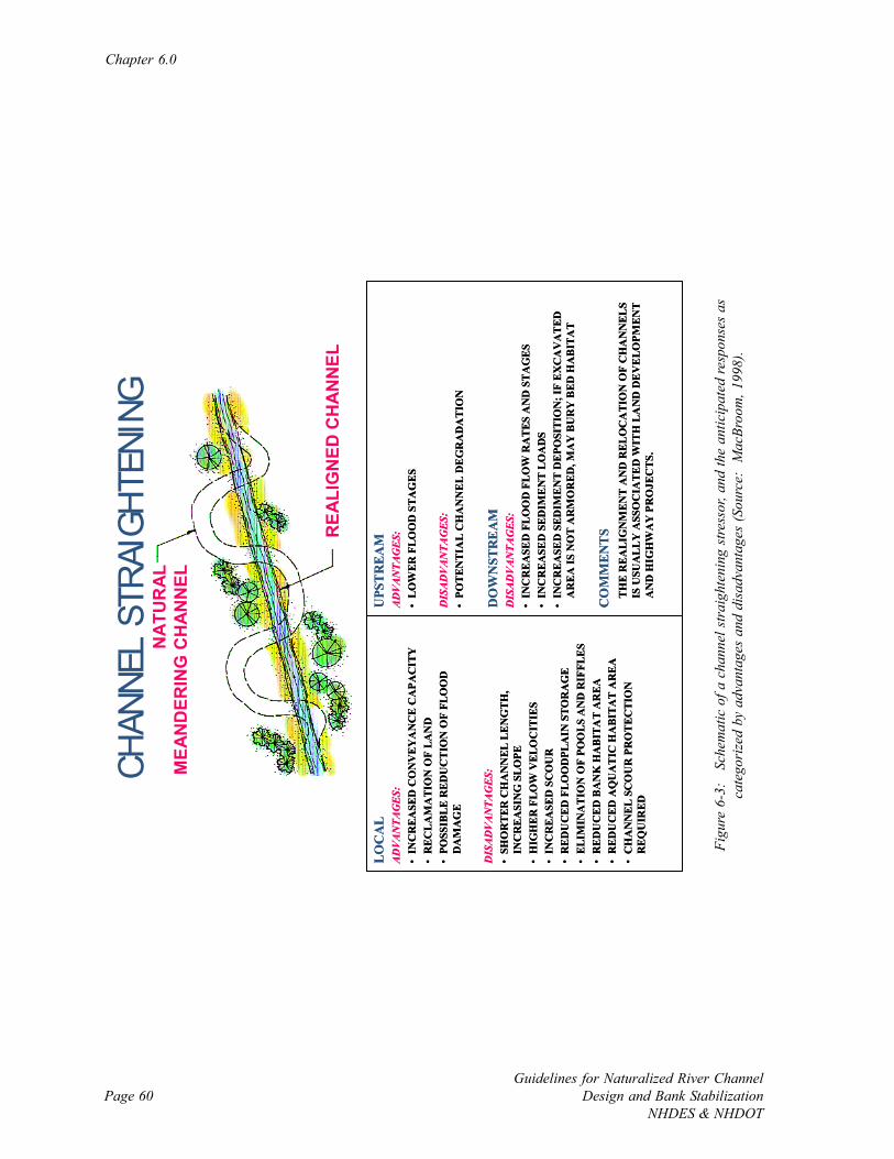
Chapter 6.0
Guidelines for Naturalized River ChannelDesign and Bank Stabilization
NHDES & NHDOTPage 60
CHAN
NEL
STRA
IGHT
ENIN
G
UPS
TR
EAM
ADVANTAGES:
•L
OW
ER F
LOO
D S
TAG
ES
DISADVANTAGES:
•PO
TEN
TIA
L C
HA
NN
EL
DE
GR
AD
ATI
ON
DO
WN
STR
EA
MDISADVANTAGES:
•IN
CR
EASE
D F
LOO
D F
LOW
RA
TES
AN
D S
TA
GE
S•
INC
REA
SED
SED
IME
NT
LO
AD
S•
INC
REA
SED
SED
IME
NT
DE
POSI
TIO
N; I
F E
XC
AV
AT
ED
AR
EA
IS N
OT
AR
MO
RED
, MA
Y B
UR
Y B
ED H
AB
ITA
T
CO
MM
ENTS
TH
E R
EA
LIG
NM
ENT
AN
D R
ELO
CA
TIO
N O
F C
HA
NN
ELS
IS U
SUA
LLY
ASS
OC
IATE
D W
ITH
LA
ND
DE
VE
LOPM
ENT
AN
D H
IGH
WA
Y P
RO
JEC
TS.
LOC
AL
ADVANTAGES:
•IN
CR
EASE
D C
ON
VE
YA
NC
E C
APA
CIT
Y•
REC
LA
MA
TIO
N O
F LA
ND
•PO
SSIB
LE R
EDU
CT
ION
OF
FLO
OD
D
AM
AG
E
DISADVANTAGES:
•SH
OR
TER
CH
AN
NEL
LE
NG
TH,
INC
REA
SIN
G S
LO
PE•
HIG
HE
R F
LOW
VEL
OC
ITIE
S•
INC
REA
SED
SC
OU
R•
RED
UC
ED F
LOO
DPL
AIN
STO
RA
GE
•EL
IMIN
AT
ION
OF
POO
LS A
ND
RIF
FLE
S•
RED
UC
ED B
AN
K H
AB
ITA
T A
REA
•R
EDU
CED
AQ
UA
TIC
HA
BIT
AT
AR
EA
•C
HA
NN
EL
SCO
UR
PR
OT
ECTI
ON
R
EQU
IRED
NA
TUR
AL
MEA
ND
ERIN
G C
HA
NN
EL
REA
LIG
NED
CH
AN
NEL
Figu
re 6
-3:
Sch
emat
ic o
f a c
hann
el s
trai
ghte
ning
stre
ssor
, and
the
antic
ipat
ed re
spon
ses
asca
tego
rize
d by
adv
anta
ges
and
disa
dvan
tage
s (S
ourc
e: M
acBr
oom
, 199
8).
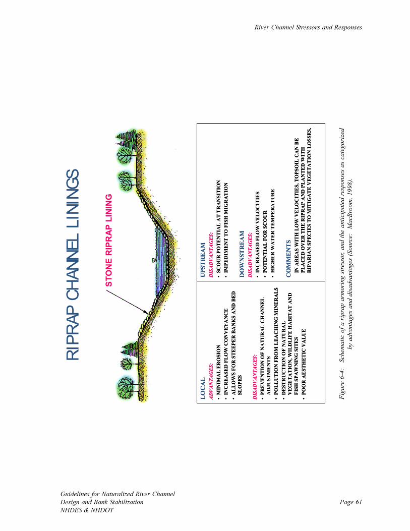
River Channel Stressors and Responses
Guidelines for Naturalized River ChannelDesign and Bank StabilizationNHDES & NHDOT
Page 61
RIPR
AP C
HANN
EL L
ININ
GS
UPS
TR
EAM
DISADVANTAGES:
•SC
OU
R P
OTE
NTI
AL
AT
TR
AN
SITI
ON
•IM
PED
IMEN
T TO
FIS
H M
IGR
ATI
ON
DO
WN
STR
EA
MDISADVANTAGES:
•IN
CR
EASE
D F
LOW
VEL
OC
ITIE
S•
POTE
NTI
AL
FOR
SC
OU
R•
HIG
HER
WA
TER
TEM
PER
ATU
RE
CO
MM
ENTS
IN A
REA
S W
ITH
LO
W V
ELO
CIT
IES,
TO
PSO
IL C
AN
BE
PLA
CE
D O
VER
TH
E R
IPR
AP
AN
D P
LAN
TED
WIT
H
RIP
AR
IAN
SPE
CIE
S TO
MIT
IGA
TE V
EGET
AT
ION
LO
SSES
.
LOC
AL
ADVANTAGES:
•M
INIM
AL
ERO
SIO
N•
INC
REA
SED
FLO
W C
ON
VEY
AN
CE
•A
LLO
WS
FOR
STE
EPER
BA
NK
S A
ND
BED
SL
OPE
S
DISADVANTAGES:
•PR
EVEN
TIO
N O
F N
ATU
RA
L C
HA
NN
EL
AD
JUST
MEN
TS•
POLL
UTI
ON
FR
OM
LEA
CH
ING
MIN
ERA
LS•
DES
TRU
CTI
ON
OF
NA
TUR
AL
VEG
ETA
TIO
N, W
ILD
LIFE
HA
BITA
T A
ND
FI
SH S
PAW
NIN
G S
ITES
•PO
OR
AES
THET
IC V
ALU
E
STO
NE
RIP
RA
P LI
NIN
G
Figu
re 6
-4:
Sch
emat
ic o
f a r
ipra
p ar
mor
ing
stre
ssor
, and
the
antic
ipat
ed re
spon
ses
as c
ateg
oriz
edby
adv
anta
ges
and
disa
dvan
tage
s (S
ourc
e: M
acBr
oom
, 199
8).
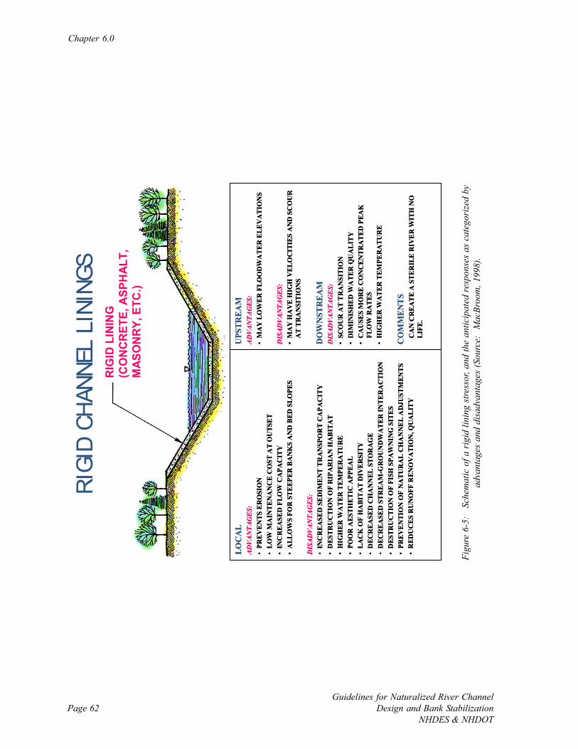
Chapter 6.0
Guidelines for Naturalized River ChannelDesign and Bank Stabilization
NHDES & NHDOTPage 62
RIGI
D CH
ANNE
L LI
NING
S
UPS
TREA
MADVANTAGES:
•M
AY
LO
WER
FLO
OD
WA
TER
ELE
VA
TIO
NS
DISADVANTAGES:
•M
AY
HA
VE
HIG
H V
ELO
CIT
IES
AN
D S
CO
UR
A
T TR
AN
SITI
ON
S
DO
WN
STR
EAM
DISADVANTAGES:
•SC
OU
R A
T T
RA
NSI
TIO
N•
DIM
INIS
HED
WA
TER
QU
ALI
TY
•C
AU
SES
MO
RE
CO
NC
EN
TRA
TED
PEA
K
FLO
W R
ATE
S•
HIG
HER
WA
TER
TEM
PER
ATU
RE
CO
MM
EN
TS
CA
N C
RE
ATE
A S
TER
ILE
RIV
ER
WIT
H N
O
LIFE
.
LOC
AL
ADVANTAGES:
•PR
EVEN
TS E
RO
SIO
N•
LOW
MA
INTE
NA
NC
E C
OST
AT
OU
TSET
•IN
CR
EASE
D F
LOW
CA
PAC
ITY
•A
LLO
WS
FOR
STE
EPER
BA
NK
S A
ND
BED
SLO
PES
DISADVANTAGES:
•IN
CR
EASE
D S
EDIM
ENT
TRA
NSP
OR
T C
APA
CIT
Y•
DES
TRU
CTI
ON
OF
RIP
AR
IAN
HA
BIT
AT
•H
IGH
ER W
AT
ER T
EMPE
RA
TUR
E•
POO
R A
ESTH
ET
IC A
PPE
AL
•LA
CK
OF
HA
BITA
T D
IVE
RSI
TY•
DEC
REA
SED
CH
AN
NEL
STO
RA
GE
•D
ECR
EASE
D S
TREA
M-G
RO
UN
DW
ATE
R IN
TER
AC
TIO
N•
DES
TRU
CTI
ON
OF
FISH
SPA
WN
ING
SIT
ES•
PREV
ENTI
ON
OF
NA
TUR
AL
CH
AN
NEL
AD
JUST
MEN
TS•
RED
UC
ES R
UN
OFF
REN
OV
ATI
ON
, QU
ALI
TY
RIG
ID L
ININ
G(C
ON
CR
ETE,
ASP
HA
LT,
MAS
ON
RY,
ETC
.)
Figu
re 6
-5:
Sch
emat
ic o
f a r
igid
lini
ng s
tress
or, a
nd th
e an
ticip
ated
resp
onse
s as
cat
egor
ized
by
adva
ntag
es a
nd d
isad
vant
ages
(Sou
rce:
Mac
Broo
m, 1
998)
.
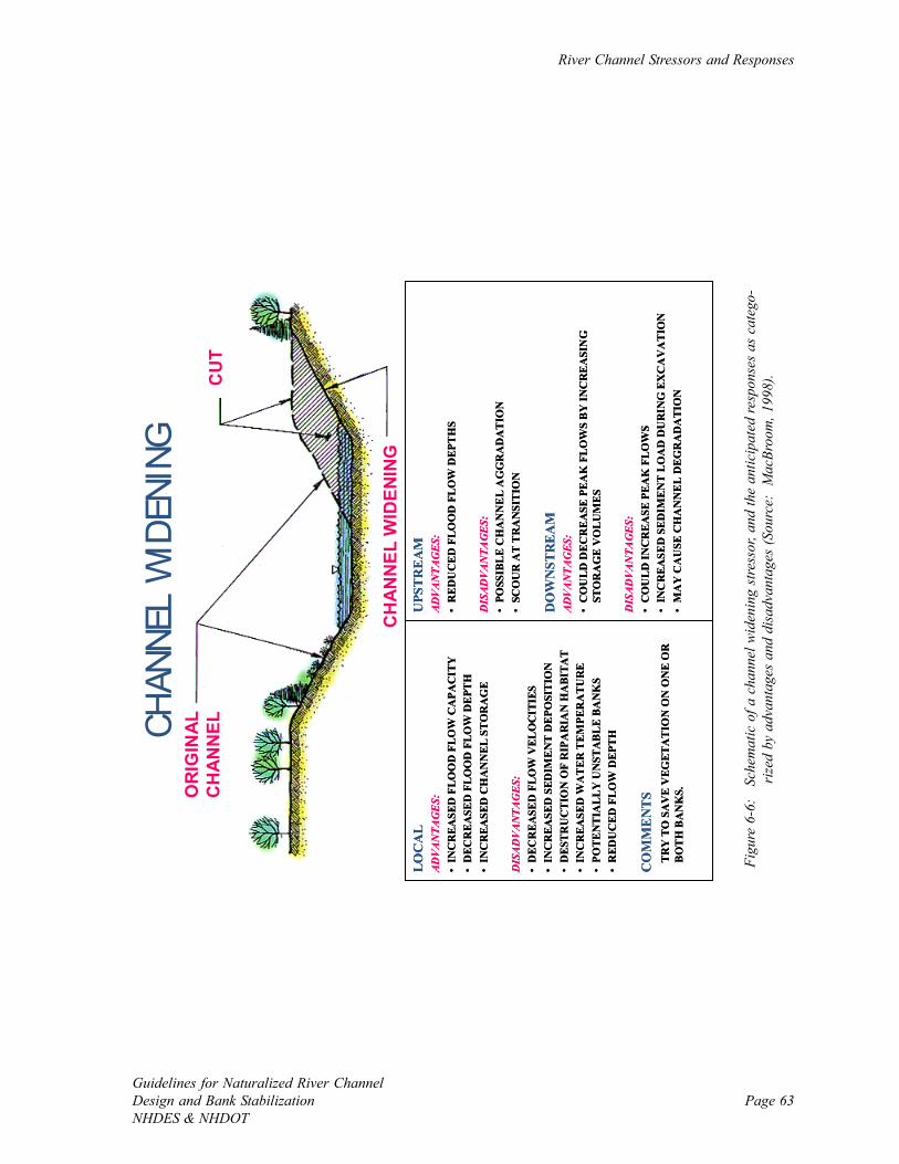
River Channel Stressors and Responses
Guidelines for Naturalized River ChannelDesign and Bank StabilizationNHDES & NHDOT
Page 63
CHAN
NEL
WID
ENIN
G
UPS
TRE
AM
ADVANTAGES:
•R
EDU
CED
FLO
OD
FLO
W D
EPTH
S
DISADVANTAGES:
•PO
SSIB
LE
CH
AN
NE
L A
GG
RA
DA
TIO
N•
SCO
UR
AT
TR
AN
SITI
ON
DO
WN
STR
EA
MADVANTAGES:
•C
OU
LD D
ECR
EASE
PEA
K F
LOW
S B
Y IN
CR
EA
SIN
G
STO
RA
GE
VO
LUM
ES
DISADVANTAGES:
•C
OU
LD IN
CR
EASE
PEA
K F
LOW
S•
INC
REA
SED
SED
IMEN
T LO
AD
DU
RIN
G E
XC
AV
ATI
ON
•M
AY
CA
USE
CH
AN
NE
L D
EGR
AD
ATI
ON
LOC
AL
ADVANTAGES:
•IN
CR
EASE
D F
LOO
D F
LOW
CA
PAC
ITY
•D
ECR
EASE
D F
LOO
D F
LOW
DEP
TH•
INC
REA
SED
CH
AN
NEL
STO
RA
GE
DISADVANTAGES:
•D
ECR
EASE
D F
LOW
VEL
OC
ITIE
S•
INC
REA
SED
SED
IMEN
T D
EPO
SITI
ON
•D
ESTR
UC
TIO
N O
F R
IPA
RIA
N H
ABI
TAT
•IN
CR
EASE
D W
AT
ER T
EMPE
RA
TUR
E•
POTE
NTI
ALL
Y U
NST
AB
LE B
AN
KS
•R
EDU
CED
FLO
W D
EPTH
CO
MM
EN
TS
TRY
TO
SA
VE
VEG
ETA
TIO
N O
N O
NE
OR
B
OTH
BA
NK
S.
UPS
TRE
AM
ADVANTAGES:
•R
EDU
CED
FLO
OD
FLO
W D
EPTH
S
DISADVANTAGES:
•PO
SSIB
LE
CH
AN
NE
L A
GG
RA
DA
TIO
N•
SCO
UR
AT
TR
AN
SITI
ON
DO
WN
STR
EA
MADVANTAGES:
•C
OU
LD D
ECR
EASE
PEA
K F
LOW
S B
Y IN
CR
EA
SIN
G
STO
RA
GE
VO
LUM
ES
DISADVANTAGES:
•C
OU
LD IN
CR
EASE
PEA
K F
LOW
S•
INC
REA
SED
SED
IMEN
T LO
AD
DU
RIN
G E
XC
AV
ATI
ON
•M
AY
CA
USE
CH
AN
NE
L D
EGR
AD
ATI
ON
LOC
AL
ADVANTAGES:
•IN
CR
EASE
D F
LOO
D F
LOW
CA
PAC
ITY
•D
ECR
EASE
D F
LOO
D F
LOW
DEP
TH•
INC
REA
SED
CH
AN
NEL
STO
RA
GE
DISADVANTAGES:
•D
ECR
EASE
D F
LOW
VEL
OC
ITIE
S•
INC
REA
SED
SED
IMEN
T D
EPO
SITI
ON
•D
ESTR
UC
TIO
N O
F R
IPA
RIA
N H
ABI
TAT
•IN
CR
EASE
D W
AT
ER T
EMPE
RA
TUR
E•
POTE
NTI
ALL
Y U
NST
AB
LE B
AN
KS
•R
EDU
CED
FLO
W D
EPTH
CO
MM
EN
TS
TRY
TO
SA
VE
VEG
ETA
TIO
N O
N O
NE
OR
B
OTH
BA
NK
S.OR
IGIN
ALC
HAN
NEL
CU
T
CH
ANN
EL W
IDEN
ING
Figu
re 6
-6:
Sch
emat
ic o
f a c
hann
el w
iden
ing
stre
ssor
, and
the
antic
ipat
ed re
spon
ses
as c
ateg
o-ri
zed
by a
dvan
tage
s an
d di
sadv
anta
ges
(Sou
rce:
Mac
Broo
m, 1
998)
.
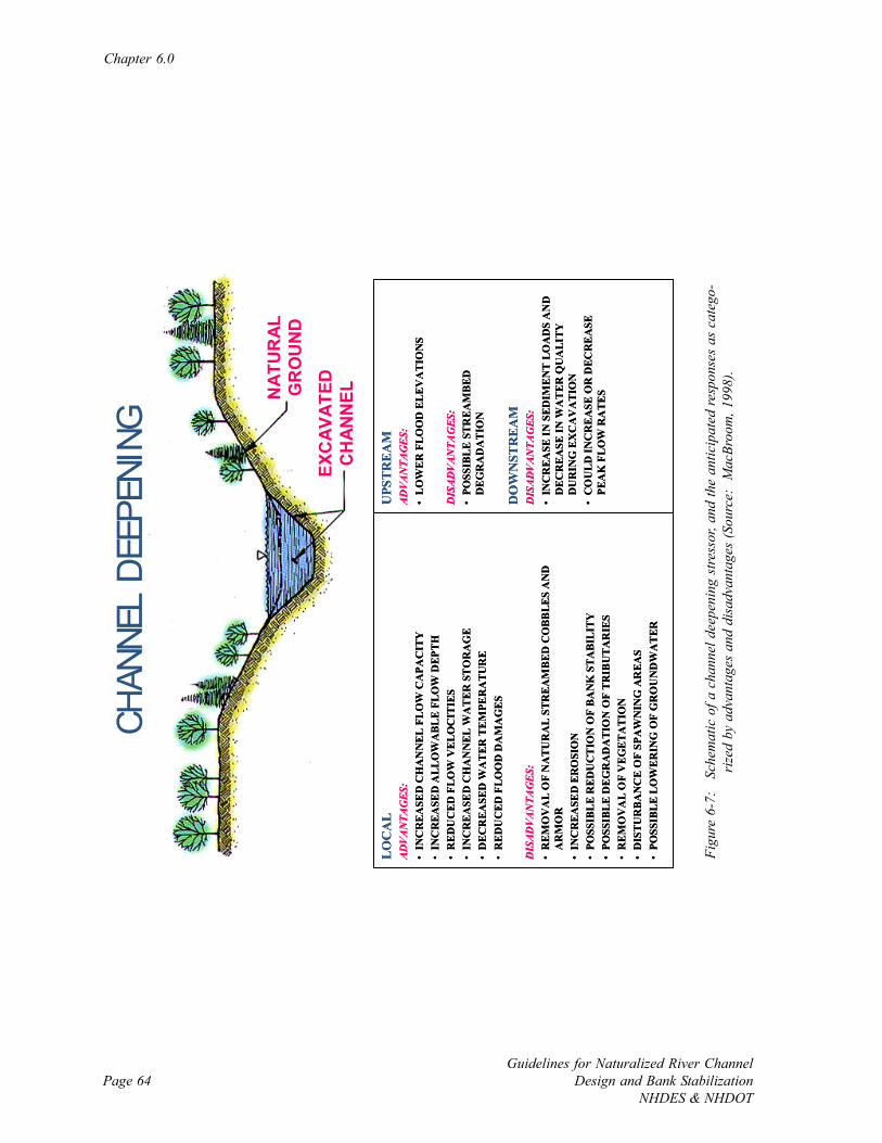
Chapter 6.0
Guidelines for Naturalized River ChannelDesign and Bank Stabilization
NHDES & NHDOTPage 64
CHAN
NEL
DEEP
ENIN
G
UPS
TR
EA
MADVANTAGES:
•LO
WER
FLO
OD
ELE
VA
TIO
NS
DISADVANTAGES:
•PO
SSIB
LE S
TREA
MB
ED
DEG
RA
DA
TIO
N
DO
WN
STR
EA
MDISADVANTAGES:
•IN
CR
EASE
IN S
EDIM
ENT
LO
AD
S A
ND
D
ECR
EASE
IN W
ATE
R Q
UA
LITY
D
UR
ING
EX
CA
VA
TIO
N•
CO
ULD
INC
REA
SE O
R D
ECR
EA
SE
PEA
K F
LOW
RA
TES
LO
CA
LADVANTAGES:
•IN
CR
EASE
D C
HA
NN
EL F
LOW
CA
PAC
ITY
•IN
CR
EASE
D A
LLO
WA
BLE
FLO
W D
EPTH
•R
EDU
CED
FLO
W V
ELO
CIT
IES
•IN
CR
EASE
D C
HA
NN
EL W
ATE
R S
TOR
AG
E•
DEC
REA
SED
WA
TER
TE
MPE
RA
TUR
E•
RED
UC
ED F
LOO
D D
AM
AG
ES
DISADVANTAGES:
•R
EMO
VA
L O
F N
ATU
RA
L S
TREA
MBE
D C
OBB
LES
AN
D
AR
MO
R•
INC
REA
SED
ER
OSI
ON
•PO
SSIB
LE R
EDU
CTI
ON
OF
BAN
K S
TABI
LITY
•PO
SSIB
LE D
EGR
AD
ATI
ON
OF
TRIB
UTA
RIE
S•
REM
OV
AL
OF
VEG
ETA
TIO
N•
DIS
TUR
BAN
CE
OF
SPA
WN
ING
AR
EAS
•PO
SSIB
LE L
OW
ERIN
G O
F G
RO
UN
DW
ATE
R
NAT
UR
ALG
RO
UN
DEX
CAV
ATED
CH
ANN
EL
Figu
re 6
-7:
Sch
emat
ic o
f a c
hann
el d
eepe
ning
stre
ssor
, and
the
antic
ipat
ed re
spon
ses
as c
ateg
o-ri
zed
by a
dvan
tage
s an
d di
sadv
anta
ges
(Sou
rce:
Mac
Broo
m, 1
998)
.
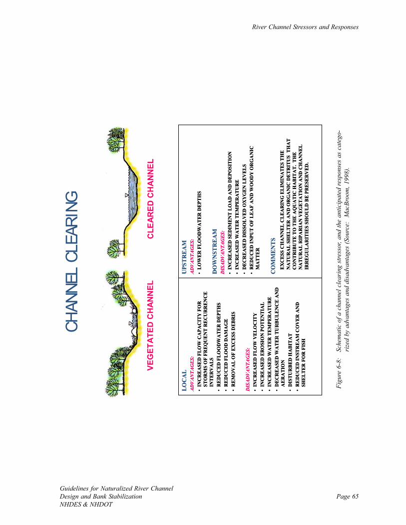
River Channel Stressors and Responses
Guidelines for Naturalized River ChannelDesign and Bank StabilizationNHDES & NHDOT
Page 65
CHAN
NEL
CLEA
RING
VEG
ETA
TED
CH
ANN
ELC
LEAR
ED C
HA
NN
EL
UPS
TR
EA
MADVANTAGES:
•LO
WER
FLO
OD
WA
TER
DEP
THS
DO
WN
STR
EA
MDISADVANTAGES:
•IN
CR
EASE
D S
EDIM
ENT
LOA
D A
ND
DEP
OSI
TIO
N•
INC
REA
SED
WA
TER
TE
MPE
RA
TUR
E•
DEC
REA
SED
DIS
SOLV
ED
OX
YG
EN L
EVEL
S•
RED
UC
ED IN
PUT
OF
LEA
F A
ND
WO
OD
Y O
RG
AN
IC
MA
TTER
CO
MM
EN
TS
EXC
ESS
CH
AN
NEL
CLE
AR
ING
ELI
MIN
ATE
S TH
E N
ATU
RA
L SH
ELT
ER A
ND
OR
GA
NIC
DET
RIT
US
TH
AT
CO
NTR
IBU
TE T
O T
HE
AQ
UA
TIC
HA
BITA
T. T
HE
NA
TUR
AL
RIP
AR
IAN
VE
GET
ATI
ON
AN
D C
HA
NN
EL
IRR
EG
ULA
RIT
IES
SHO
ULD
BE
PRES
ERV
ED.
LOC
AL
ADVANTAGES:
•IN
CR
EASE
D F
LOW
CA
PAC
ITY
FO
R
STO
RM
S O
F FR
EQU
EN
T R
ECU
RR
ENC
E IN
TER
VA
LS•
RED
UC
ED F
LOO
DW
ATE
R D
EPTH
S•
RED
UC
ED F
LOO
D D
AM
AG
E•
REM
OV
AL
OF
EXC
ESS
DEB
RIS
DISADVANTAGES:
•IN
CR
EASE
D F
LOW
VEL
OC
ITY
•IN
CR
EASE
D E
RO
SIO
N P
OTE
NTI
AL
•IN
CR
EASE
D W
AT
ER T
EMPE
RA
TUR
E•
DEC
REA
SED
WA
TER
TU
RB
ULE
NC
E A
ND
A
ERA
TIO
N•
DIS
TUR
BED
HA
BITA
T•
RED
UC
ED IN
STR
EAM
CO
VER
AN
D
SHEL
TER
FO
R F
ISH
Figu
re 6
-8:
Sch
emat
ic o
f a c
hann
el c
lear
ing
stre
ssor
, and
the
antic
ipat
ed re
spon
ses
as c
ateg
o-ri
zed
by a
dvan
tage
s an
d di
sadv
anta
ges
(Sou
rce:
Mac
Broo
m, 1
998)
.
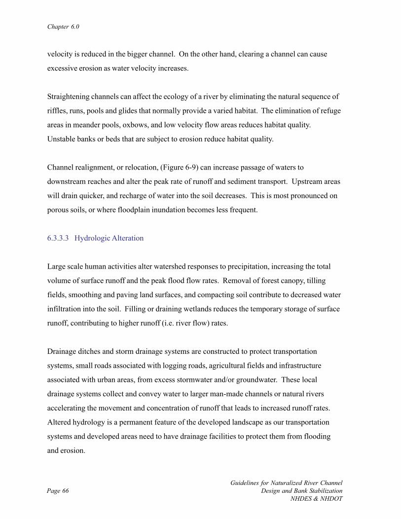
Chapter 6.0
Guidelines for Naturalized River ChannelDesign and Bank Stabilization
NHDES & NHDOTPage 66
velocity is reduced in the bigger channel. On the other hand, clearing a channel can cause
excessive erosion as water velocity increases.
Straightening channels can affect the ecology of a river by eliminating the natural sequence of
riffles, runs, pools and glides that normally provide a varied habitat. The elimination of refuge
areas in meander pools, oxbows, and low velocity flow areas reduces habitat quality.
Unstable banks or beds that are subject to erosion reduce habitat quality.
Channel realignment, or relocation, (Figure 6-9) can increase passage of waters to
downstream reaches and alter the peak rate of runoff and sediment transport. Upstream areas
will drain quicker, and recharge of water into the soil decreases. This is most pronounced on
porous soils, or where floodplain inundation becomes less frequent.
6.3.3.3 Hydrologic Alteration
Large scale human activities alter watershed responses to precipitation, increasing the total
volume of surface runoff and the peak flood flow rates. Removal of forest canopy, tilling
fields, smoothing and paving land surfaces, and compacting soil contribute to decreased water
infiltration into the soil. Filling or draining wetlands reduces the temporary storage of surface
runoff, contributing to higher runoff (i.e. river flow) rates.
Drainage ditches and storm drainage systems are constructed to protect transportation
systems, small roads associated with logging roads, agricultural fields and infrastructure
associated with urban areas, from excess stormwater and/or groundwater. These local
drainage systems collect and convey water to larger man-made channels or natural rivers
accelerating the movement and concentration of runoff that leads to increased runoff rates.
Altered hydrology is a permanent feature of the developed landscape as our transportation
systems and developed areas need to have drainage facilities to protect them from flooding
and erosion.
River Channel Stressors and Responses
Guidelines for Naturalized River ChannelDesign and Bank StabilizationNHDES & NHDOT
Page 67
CHAN
NEL
RELO
CATI
ON
UPS
TR
EA
MDISADVANTAGES:
•A
GG
RA
DA
TIO
N•
SCO
UR
AT
TR
AN
SITI
ON
•PO
SSIB
LE IN
CR
EA
SE IN
WA
TER
E
LEV
AT
ION
•PO
SSIB
LE C
HA
NG
E IN
CH
AN
NE
L PA
TTE
RN
, AL
IGN
MEN
T
DO
WN
STR
EAM
ADVANTAGES:
•D
ELA
Y O
F PE
AK
FL
OO
D F
LOW
S
DISADVANTAGES:
•D
ECR
EASE
D S
ED
IMEN
T LO
AD
, LE
AD
ING
T
O D
EG
RA
DA
TIO
N
LO
CA
LADVANTAGES:
•O
LD C
HA
NN
EL
RE
CL
AIM
ED F
OR
HU
MA
N U
SES
•IN
CR
EASE
D F
LO
OD
STO
RA
GE
IF O
LD
CH
AN
NEL
NO
T R
EC
LA
IME
D
DISADVANTAGES:
•IN
CR
EASE
D C
HA
NN
EL L
ENG
TH
•D
EC
REA
SED
CH
AN
NE
L SL
OPE
•D
EC
REA
SED
FL
OW
VEL
OC
ITY
•D
EC
REA
SED
FL
OW
CA
PAC
ITY
•A
GG
RA
DA
TIO
N D
UE
TO
INC
RE
ASE
D S
ED
IME
NT
D
EPO
SIT
ION
•D
EST
RU
CT
ION
OF
CH
AN
NEL
HA
BIT
AT
CO
MM
EN
TS
CA
REF
UL
DE
SIG
N A
ND
CR
EAT
ION
OF
NA
TU
RA
L
CO
ND
ITIO
NS
IN N
EW
CH
AN
NE
L C
AN
MIT
IGA
TE
NE
GA
TIV
E IM
PAC
TS.
REL
OC
ATE
D C
HAN
NEL
OR
IGIN
AL
CH
AN
NEL
FIL
LED
Figu
re 6
-9:
Sch
emat
ic o
f a c
hann
el re
loca
tion
stre
ssor
, and
the
antic
ipat
ed re
spon
ses
asca
tego
rize
d by
adv
anta
ges
and
disa
dvan
tage
s (S
ourc
e: M
acBr
oom
, 199
8).
Chapter 6.0
Guidelines for Naturalized River ChannelDesign and Bank Stabilization
NHDES & NHDOTPage 68
6.3.3.4 Dams
Dams (Figure 6-10) alter the flow of water and sediment to the point that natural river form
and process is an unrealistic objective of restoration unless dam removal is considered. Dams
reduce fish populations by blocking both migratory and resident species from historic
spawning grounds.
Small dams alter flow, reduce sediment transport, increase downstream water temperatures
due to solar heating in the upstream impoundment (Lessard and Hayes, 2003), and serve as
physical barriers to fish migration. The collective impact of the many small dams scattered
across virtually every river system is extensive. The removal of small dams is becoming a
popular restoration option given that many of the structures are obsolete, safety hazards, and
key sources of habitat impairment.
Large dams cause large departures from a natural flow regime, particularly downstream of
hydro-electric power plants. Unnatural flow regimes alter channel morphology and sediment
regime (Assani and Petit, 2004), reduce the overall quality of river habitat making a river
uninhabitable for some organisms, and eliminate many of the natural services provided by
rivers (Postal and Richter, 2003). Large dams trap most of the sediment moving downstream,
and substantial erosion is common on tailwater reaches due to the release of sediment-starved
water from the widened upstream impoundment (Kondolf and Swanson, 1993).
6.3.3.5 Urbanization
Urbanization and other forms of land development are accompanied by removing vegetative
ground cover, smoothing the land surface, and increasing the area of the watershed covered
with impervious or compacted surfaces. Impervious surfaces include roof tops, roadways,
driveways, and parking lots. Larger impervious areas increase the amount of surface runoff,
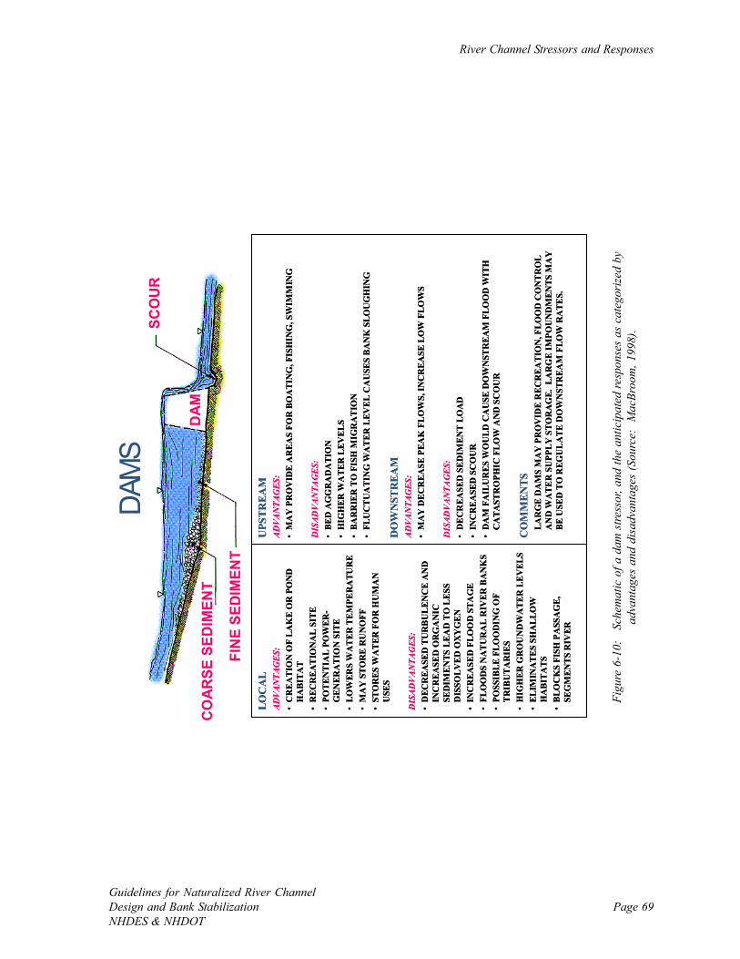
River Channel Stressors and Responses
Guidelines for Naturalized River ChannelDesign and Bank StabilizationNHDES & NHDOT
Page 69
DAM
S
UPS
TREA
MADVANTAGES:
•M
AY
PR
OV
IDE
AR
EAS
FOR
BO
ATI
NG
, FIS
HIN
G, S
WIM
MIN
G
DISADVANTAGES:
•BE
D A
GG
RA
DA
TIO
N•
HIG
HER
WA
TER
LEV
ELS
•BA
RR
IER
TO
FIS
H M
IGR
ATI
ON
•FL
UC
TU
ATI
NG
WA
TER
LEV
EL C
AU
SES
BA
NK
SLO
UG
HIN
G
DO
WN
STR
EAM
ADVANTAGES:
•M
AY
DEC
REA
SE P
EAK
FLO
WS,
INC
REA
SE L
OW
FLO
WS
DISADVANTAGES:
•D
ECR
EASE
D S
EDIM
ENT
LOA
D•
INC
REA
SED
SC
OU
R•
DA
M F
AIL
UR
ES W
OU
LD C
AU
SE D
OW
NST
REA
M F
LOO
D W
ITH
C
ATA
STR
OPH
IC F
LOW
AN
D S
CO
UR
CO
MM
ENTS
LAR
GE
DA
MS
MA
Y P
RO
VID
E R
ECR
EATI
ON
, FLO
OD
CO
NTR
OL
AN
D W
ATE
R S
UPP
LY S
TOR
AG
E. L
AR
GE
IMPO
UN
DM
ENTS
MA
Y
BE U
SED
TO
REG
UL
ATE
DO
WN
STR
EAM
FLO
W R
ATE
S.
LOC
AL
ADVANTAGES:
•C
REA
TIO
N O
F LA
KE
OR
PO
ND
H
ABI
TAT
•R
ECR
EAT
ION
AL
SITE
•PO
TEN
TIA
L PO
WER
-G
ENER
AT
ION
SIT
E•
LOW
ERS
WA
TER
TEM
PER
ATU
RE
•M
AY
STO
RE
RU
NO
FF•
STO
RES
WA
TER
FO
R H
UM
AN
U
SES
DISADVANTAGES:
•D
ECR
EASE
D T
UR
BU
LEN
CE
AN
D
INC
REA
SED
OR
GA
NIC
SE
DIM
ENTS
LEA
D T
O L
ESS
DIS
SOLV
ED O
XY
GEN
•IN
CR
EASE
D F
LOO
D S
TAG
E•
FLO
OD
S N
ATU
RA
L R
IVER
BA
NK
S•
POSS
IBLE
FLO
OD
ING
OF
TRIB
UTA
RIE
S•
HIG
HER
GR
OU
ND
WA
TER
LEV
ELS
•EL
IMIN
ATE
S SH
ALL
OW
H
ABI
TATS
•B
LOC
KS
FISH
PA
SSA
GE,
SE
GM
ENTS
RIV
ER
DA
M
SCO
UR
CO
AR
SE S
EDIM
ENT
FIN
E SE
DIM
ENT
Figu
re 6
-10:
Sc
hem
atic
of a
dam
stre
ssor
, and
the
antic
ipat
ed re
spon
ses
as c
ateg
oriz
ed b
yad
vant
ages
and
dis
adva
ntag
es (S
ourc
e: M
acBr
oom
, 199
8).

Chapter 6.0
Guidelines for Naturalized River ChannelDesign and Bank Stabilization
NHDES & NHDOTPage 70
Figure 6-11: Pre- and post-development hydrographs thatshow an increase in runoff and higher peak flows following a
change in land use (Source: EPA, 1997).
decrease infiltration and decreases
the time water remains in its
watershed, altering natural flows
(USEPA, 1997) (Figure 6-11). The
USGS study (2006) on impervious
cover in the New Hampshire
seacoast watershed indicated impacts
at less than 10% imperviousness.
The 10% level is a common
watershed development threshold
often cited in the scientific literature
(e.g., CWP, 2003), beyond which
impacts to hydrology, fluvial geomorphology, water quality, and aquatic habitat take place. In
addition, the presence of storm sewers and curbs increases the velocity of surface runoff,
decreases residence time in the watershed, and allows runoff to rapidly concentrate in rivers.
The combination of larger runoff amounts and faster concentration times can drastically
change the flow rates in rivers. Urbanization will also increase the magnitude and frequency
of mean annual and bankfull flows in the river. Urbanization also reduces the infiltration of
water into the soil and the storage of surface water leading to a long-term reduction in low
flows. As a result of higher peak flow rates and the greater frequency at which they occur,
alluvial river channels in urban areas often tend to enlarge by horizontal widening and vertical
degradation.
Modern stormwater management practices help reduce the hydrologic impact of urbanization.
The use of detention basins, infiltration systems, low impact development, and erosion
controls are an important part of river management.
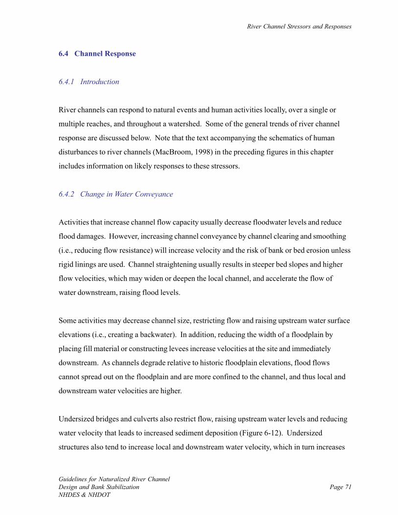
River Channel Stressors and Responses
Guidelines for Naturalized River ChannelDesign and Bank StabilizationNHDES & NHDOT
Page 71
6.4 Channel Response
6.4.1 Introduction
River channels can respond to natural events and human activities locally, over a single or
multiple reaches, and throughout a watershed. Some of the general trends of river channel
response are discussed below. Note that the text accompanying the schematics of human
disturbances to river channels (MacBroom, 1998) in the preceding figures in this chapter
includes information on likely responses to these stressors.
6.4.2 Change in Water Conveyance
Activities that increase channel flow capacity usually decrease floodwater levels and reduce
flood damages. However, increasing channel conveyance by channel clearing and smoothing
(i.e., reducing flow resistance) will increase velocity and the risk of bank or bed erosion unless
rigid linings are used. Channel straightening usually results in steeper bed slopes and higher
flow velocities, which may widen or deepen the local channel, and accelerate the flow of
water downstream, raising flood levels.
Some activities may decrease channel size, restricting flow and raising upstream water surface
elevations (i.e., creating a backwater). In addition, reducing the width of a floodplain by
placing fill material or constructing levees increase velocities at the site and immediately
downstream. As channels degrade relative to historic floodplain elevations, flood flows
cannot spread out on the floodplain and are more confined to the channel, and thus local and
downstream water velocities are higher.
Undersized bridges and culverts also restrict flow, raising upstream water levels and reducing
water velocity that leads to increased sediment deposition (Figure 6-12). Undersized
structures also tend to increase local and downstream water velocity, which in turn increases
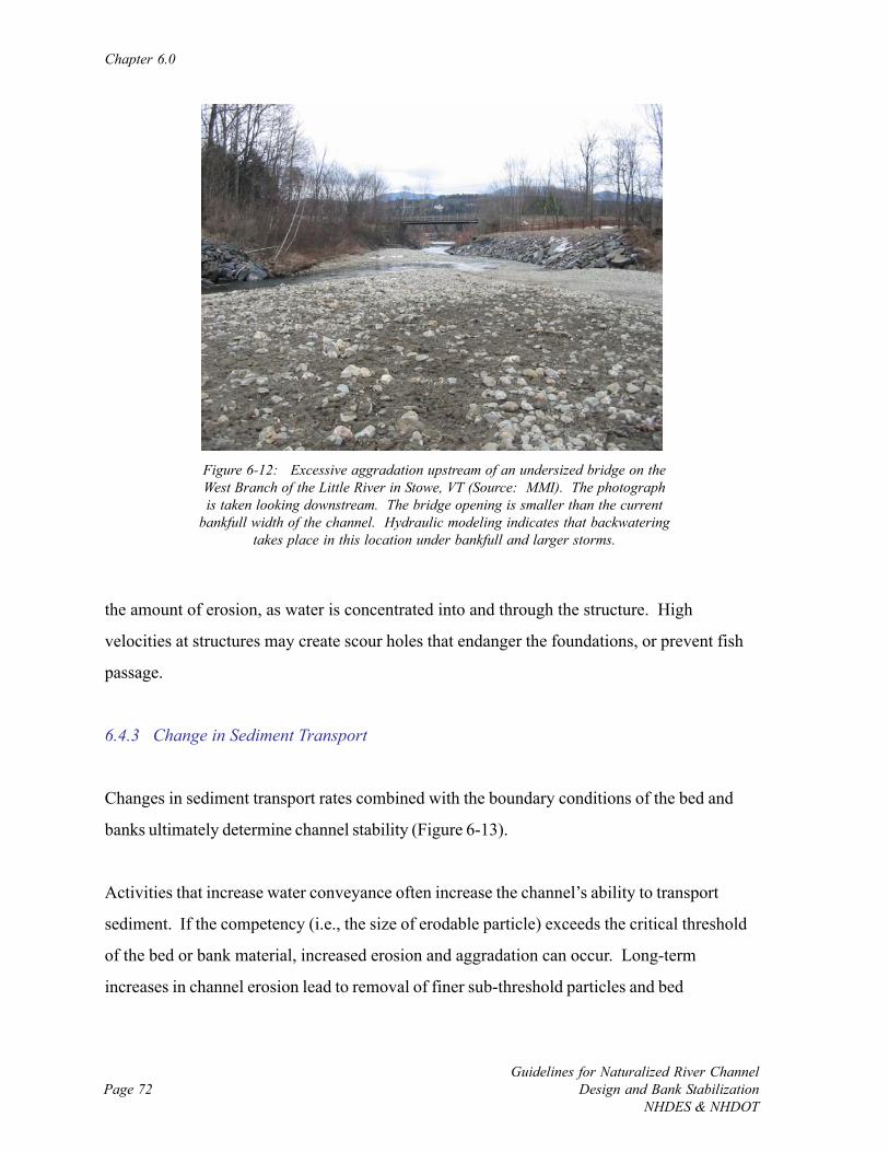
Chapter 6.0
Guidelines for Naturalized River ChannelDesign and Bank Stabilization
NHDES & NHDOTPage 72
Figure 6-12: Excessive aggradation upstream of an undersized bridge on theWest Branch of the Little River in Stowe, VT (Source: MMI). The photographis taken looking downstream. The bridge opening is smaller than the current
bankfull width of the channel. Hydraulic modeling indicates that backwateringtakes place in this location under bankfull and larger storms.
the amount of erosion, as water is concentrated into and through the structure. High
velocities at structures may create scour holes that endanger the foundations, or prevent fish
passage.
6.4.3 Change in Sediment Transport
Changes in sediment transport rates combined with the boundary conditions of the bed and
banks ultimately determine channel stability (Figure 6-13).
Activities that increase water conveyance often increase the channel’s ability to transport
sediment. If the competency (i.e., the size of erodable particle) exceeds the critical threshold
of the bed or bank material, increased erosion and aggradation can occur. Long-term
increases in channel erosion lead to removal of finer sub-threshold particles and bed
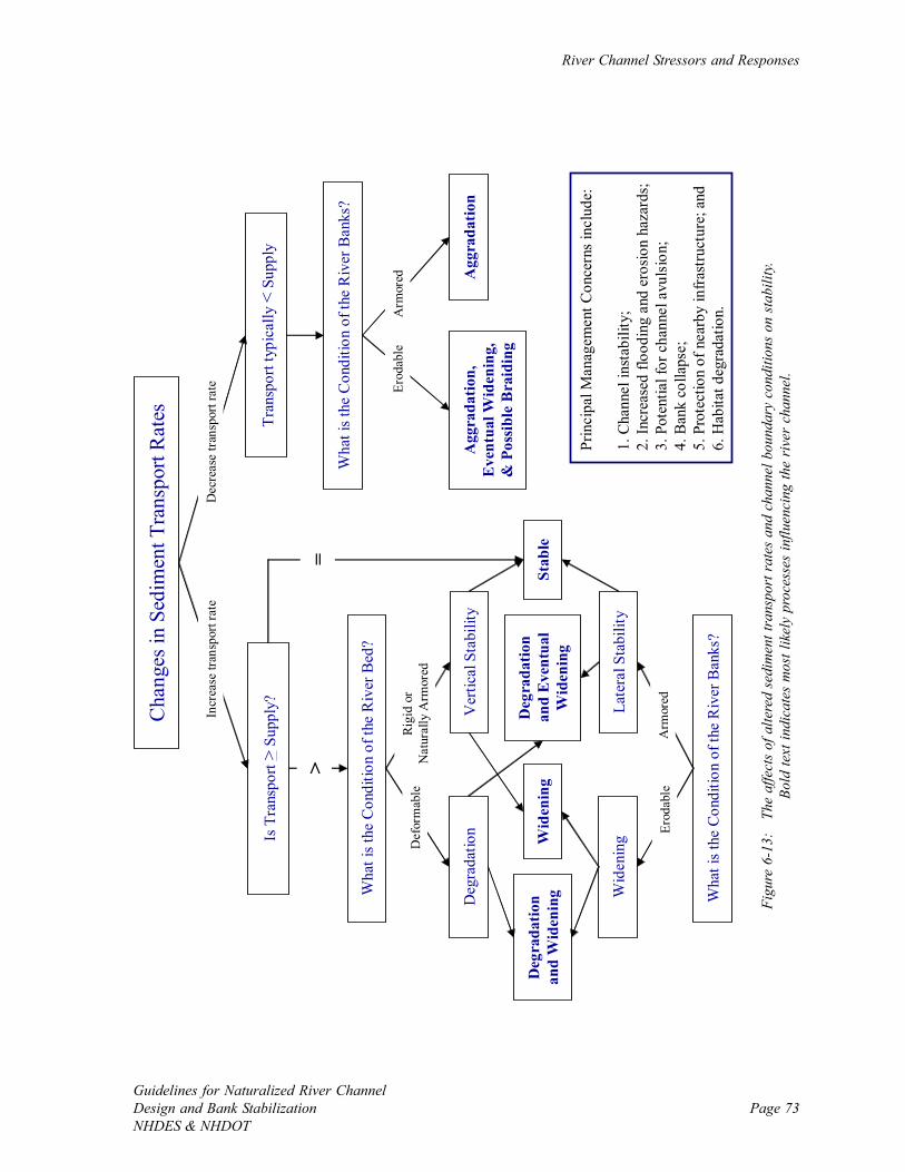
River Channel Stressors and Responses
Guidelines for Naturalized River ChannelDesign and Bank StabilizationNHDES & NHDOT
Page 73
Cha
nges
in S
edim
ent T
rans
port
Rat
es
Is T
rans
port
>Su
pply
?
Incr
ease
tran
spor
t rat
eD
ecre
ase
trans
port
rate
Tran
spor
t typ
ical
ly <
Supp
ly
Stab
le
Wha
t is t
he C
ondi
tion
of th
e R
iver
Bed
?
>=
Rigi
d or
Nat
ural
ly A
rmor
ed
Wha
t is t
he C
ondi
tion
of th
e R
iver
Ban
ks?
Arm
ored
Def
orm
able
Erod
able
Ver
tical
Sta
bilit
y
Late
ral S
tabi
lity
Deg
rada
tion
Wid
enin
gWid
enin
gD
egra
datio
n an
d W
iden
ing
Deg
rada
tion
and
Even
tual
W
iden
ing
Wha
t is t
he C
ondi
tion
of th
e R
iver
Ban
ks?
Erod
able
Arm
ored
Agg
rada
tion,
E
vent
ual W
iden
ing,
&
Pos
sibl
e B
raid
ing
Agg
rada
tion
Prin
cipa
l Man
agem
ent C
once
rns
incl
ude:
1. C
hann
el in
stab
ility
;2.
Incr
ease
d flo
odin
g an
d er
osio
n ha
zard
s;3.
Pot
entia
l for
cha
nnel
avu
lsio
n;4.
Ban
k co
llaps
e;5.
Pro
tect
ion
of n
earb
y in
frast
ruct
ure;
and
6. H
abita
t deg
rada
tion.
Figu
re 6
-13:
Th
e af
fect
s of
alte
red
sedi
men
t tra
nspo
rt r
ates
and
cha
nnel
bou
ndar
y co
nditi
ons
on s
tabi
lity.
Bold
text
indi
cate
s m
ost l
ikel
y pr
oces
ses
influ
enci
ng th
e ri
ver
chan
nel.
Chapter 6.0
Guidelines for Naturalized River ChannelDesign and Bank Stabilization
NHDES & NHDOTPage 74
Figure 6-14: Photograph of channel degradation and widening onWarren Brook in Alstead, NH (Source: Horizons Engineering, LLC).
degradation. If sufficient large particles remain, the river bed may become naturally armored
and stabilize, leaving just the banks still subject to erosion and channel widening.
Reducing the river’s ability to transport sediment by reducing its slope or diverting water (i.e.,
lowering water velocity) can lead to sediment deposition and channel aggradation.
6.4.4 Channel Degradation
Degradation is the general long-term lowering of a river bed or the rapid down-cutting of a
channel during floods (Figure 6-14). It occurs where the channel’s slope, discharge, and
substrate size allow for the transport of more sediment than is supplied to a river reach. The
river will erode its bed until the slope and velocity are reduced to a point where the river bed
erosion no longer produces additional sediment.
Degradation can occur as a uniform lowering of the bed if the factors inducing the erosion are
consistent throughout a channel reach. In other cases, the degradation can occur in the form
of upstream migration of small erosion fronts called head cuts. In effect, two graded portions
of the river are separated by a local steep point, or a nick point, where active degradation
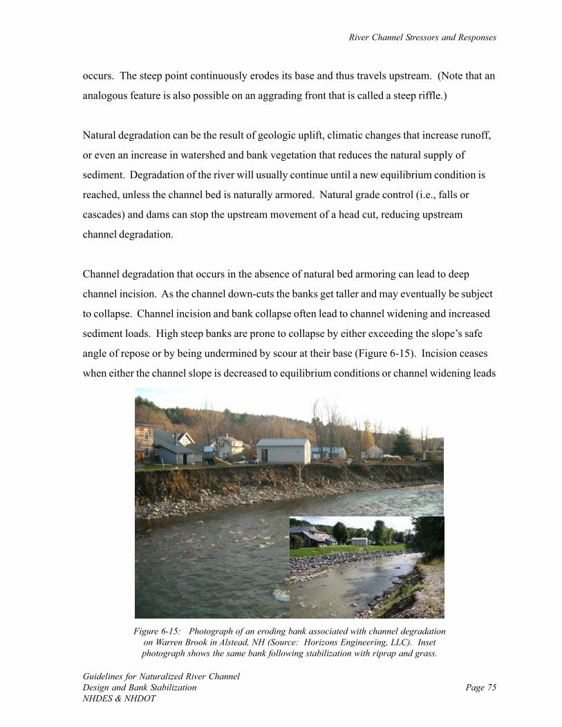
River Channel Stressors and Responses
Guidelines for Naturalized River ChannelDesign and Bank StabilizationNHDES & NHDOT
Page 75
Figure 6-15: Photograph of an eroding bank associated with channel degradationon Warren Brook in Alstead, NH (Source: Horizons Engineering, LLC). Insetphotograph shows the same bank following stabilization with riprap and grass.
occurs. The steep point continuously erodes its base and thus travels upstream. (Note that an
analogous feature is also possible on an aggrading front that is called a steep riffle.)
Natural degradation can be the result of geologic uplift, climatic changes that increase runoff,
or even an increase in watershed and bank vegetation that reduces the natural supply of
sediment. Degradation of the river will usually continue until a new equilibrium condition is
reached, unless the channel bed is naturally armored. Natural grade control (i.e., falls or
cascades) and dams can stop the upstream movement of a head cut, reducing upstream
channel degradation.
Channel degradation that occurs in the absence of natural bed armoring can lead to deep
channel incision. As the channel down-cuts the banks get taller and may eventually be subject
to collapse. Channel incision and bank collapse often lead to channel widening and increased
sediment loads. High steep banks are prone to collapse by either exceeding the slope’s safe
angle of repose or by being undermined by scour at their base (Figure 6-15). Incision ceases
when either the channel slope is decreased to equilibrium conditions or channel widening leads

Chapter 6.0
Guidelines for Naturalized River ChannelDesign and Bank Stabilization
NHDES & NHDOTPage 76
Figure 6-16: Photograph of an aggradational feature at theconfluence of Bowers Brook and Cold River in Acworth, NH taken in
August 2006 (Source: Horizons Engineering, LLC).
to decreased flow depths and lower shear stress. In addition, if incision leads to head cuts that
migrate up a coarse-grained channel, the upstream degradation can add to the downstream
sediment supply and slow the downstream incision.
Incision results in lower water levels in the channel relative to the top of bank and also can
lower nearby ground water levels. Incision also decreases the frequency and depth of
floodplain inundation, and gradually the river is disconnected from riparian wetlands and the
floodplain.
6.4.5 Channel Aggradation
Aggradation is the general increase in elevation of a long reach of a riverbed over a long-term
period (Figure 6-16). It is a process of deposition in which sediment is continually added to
the riverbed, and possibly even to the floodplain. Aggradation occurs when the river does not
have sufficient slope, velocity, or flow rate to transport the sediment load of a given size
distribution. The riverbed and floodplain elevations will increase until equilibrium is reached
with sediment transport being equal to sediment supply rates.
River Channel Stressors and Responses
Guidelines for Naturalized River ChannelDesign and Bank StabilizationNHDES & NHDOT
Page 77
The reach downstream of an aggrading reach may have an increase in slope as the aggrading
reach is raised above the previous bed level. This new steeper slope will increase the
channel’s sediment transport rate until a new equilibrium is reached.
The slope of the riverbed upstream of an aggrading reach is reduced by the downstream
deposits. This reduction in slope reduces sediment transport and hence the area of deposition
will migrate upstream, with progressively finer material being deposited due to the lower
transport capacity. The sediments will be segregated by weight into stratified layers sloping
downstream.
The aggrading channel often becomes wide and braided as it fills with new sediment and the
water carves out multiple flow paths through the deposits. If the channel is not too incised
overbank flows on the floodplain will take place more frequently leaving sediment deposits on
the floodplain’s surface. Thus, the floodplain surface may rise with the river, but at a slower
rate. Aggrading channels often tend to widen in order to maintain their cross-sectional area.
Among the factors that lead to increased sediment deposition and channel aggradation are: a
decrease in watershed vegetation leading to increased surface erosion (e.g., logging,
development in the river corridor); climatic changes reducing runoff rates; and excessive
infiltration in coarse alluvium.
6.4.6 River Bank Erosion
River bank erosion is one of the most common responses to external changes in water
conveyance or sediment loads. Excessive bank erosion causes economic losses such as loss of
land and private property damage. The sediment caused by excessive bank erosion can
degrade water quality and reduce habitat quality.
Alluvial channels that have formed in erodable soils, and even some formed in more
compacted glacial till, often have natural bank erosion on the outside of meander bends, in
Chapter 6.0
Guidelines for Naturalized River ChannelDesign and Bank Stabilization
NHDES & NHDOTPage 78
reaches where the channel width is narrows, in areas where the banks have been compromised
by ice abrasion, and in areas subject to high flow velocity. Extensive bank erosion and general
channel enlargement occurs during floods.
Excessive sediment loads may also contribute to bank erosion. Deposition of coarse gravel
and cobble sediments in the channel reduces cross-sectional area, and may encourage erosion
of the banks when bank materials are finer than deposited bed materials resulting in channel
widening. Braided channels, with many mid-channel bars and islands, are notoriously
unstable.
Bank erosion may consist of the detachment and removal of local particles, mass failures of
larger areas of soil that are undermined at or below the water line, and loss of river bank trees
and roots. The assessment of both gradual bank erosion and mass failures is complex because
these processes occur naturally resulting from normal channel adjustments. In many cases the
river bank will adjust its shape and naturally re-vegetate. However, stressors can cause
excessive bank erosion that release large volumes of new sediment that may require corrective
action. In addition, the presence of infrastructure and private investments often leads to the
desire to reduce even normal rates of bank erosion, which would typically heal on their own
given ample space and time. Typical methods of bank stabilization are presented in Chapter
10.0 of this manual.
6.4.6.1 Channel Widening
Channel widening is used to describe situations where there is bank erosion occurring on both
sides of a river channel. Unlike simple bank erosion which naturally occurs in limited areas
such as along bends or contractions, channel widening implies a net increase in the waterway’s
width over a sizeable length.
Channel widening may occur naturally due to major floods or it may be encouraged by the
increased peak flood flow rates attributed to watershed changes. Widening is also associated
River Channel Stressors and Responses
Guidelines for Naturalized River ChannelDesign and Bank StabilizationNHDES & NHDOT
Page 79
with excessive channel degradation and aggradation, such as that common near a dam. Unlike
common local bank erosion problem that often do not call for management, channel widening
suggests the river channel is undersized for the modern flow rates.
Widened channels that convey large flood flows typically have featureless (i.e., plane) beds
and shallow water depths under normal and low flow conditions that have poor aquatic
habitat. The breaks in the forest canopy on over-widened channels tend to allow excessive
growth of invasive plants such as Japanese knotweed (Fallopia japonica), tartarian
honeysuckle (Lonicera tatarica), and garlic mustard (Alliaria petiolata).
6.4.7 Channel Avulsion
Channel avulsion occurs when there is a rapid and dramatic change in the river’s alignment.
Avulsions usually occur during floods when waters overtop the banks and scour a new flow
path, generally across a low floodplain. Classic examples of channel avulsion occur on
sinuous alluvial rivers when floodwaters carve a new straight channel across a meander bend,
creating a meander chute cut-off that bypasses the original channel. An oxbow can form if the
river channel migrates away from and isolates the meander bend that has been short circuited.
Human activities can lead to channel avulsion. Clearing riparian forest cover from low
floodplains reduces roughness and encourages higher overbank flow velocities that can lead to
meander chute cut-offs. Channel avulsions are also possible where sand and gravel material is
excavated from floodplains. Long linear floodplain ponds associated with former gravel
extraction sites are typically often subject to avulsion as they provide a low resistance
pathway that captures the river. Three relatively recent New Hampshire examples of channel
avulsion are the Suncook River in Epsom (Figure 6-17), Pemigewasset River near I-93 Exit
31, and Mad River near I-93 Exit 28.
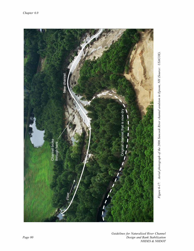
Chapter 6.0
Guidelines for Naturalized River ChannelDesign and Bank Stabilization
NHDES & NHDOTPage 80
Figu
re 6
-17:
Ae
rial
pho
togr
aph
of th
e 20
06 S
unco
ok R
iver
cha
nnel
avu
lsio
n in
Eps
om, N
H (S
ourc
e: U
SAC
OE)
.
Orig
inal
cha
nnel
that
is n
ow d
ry
Cha
nnel
bro
ke
thro
ugh
here
Flow
New
cha
nnel
Page 81Guidelines for Naturalized River ChannelDesign and Bank StabilizationNHDES & NHDOT
CHAPTER 7.0: HYDROLOGY
7.1 Introduction
Hydrology is one of the primary variables that determine the dynamic shape of a river and its
physical processes. Flows and their pattern of variability are also the foundation of the
aquatic and riparian zone ecosystems. Naturalized river channel and bank stabilization
projects should be designed with consideration of a range of flows that determine the physical
stability, ecological integrity, and chemical composition of a river system. Designs that
consider a range of flows are likely to perform as planned over longer periods of time than
traditional designs that rely on a single flood event (e.g., 100-year or bankfull floods). Good
hydrology practice is to determine a range of design flows via several methods and compare
results. For all but the simplest of projects, direct flow measurements are compared to
estimations that are generated from either simple calculations or more involved models.
Current estimates of system hydrology are also compared to any initial project hydrology data
(Chapter 3.0) such as found in existing Federal Emergency Management Agency (FEMA)
flood insurance studies, past projects, and watershed studies.
The level of recommended hydrology analysis is a function of whether a project is classified as
routine, moderate, or comprehensive (Figure 7-1). Simple design flow estimation is adequate
for routine projects that are small in scope and have low site constraints. In this case a range
of flows can be approximated from hydraulic geometry curves, basic regression-based models,
or using regional flow estimations based on watershed size. More involved projects generally
require additional analyses to expand the determination of hydrology at the project site –
instantaneous measurements of flow and gage analysis. If the gage happens to be located on
the river where the project is taking place data can be directly used; however, more frequently
flow statistics are approximated from surrogate gage data by scaling via watershed area or
data correlation. Multiple flow calculations and measurements are used to compare design
flows estimations.
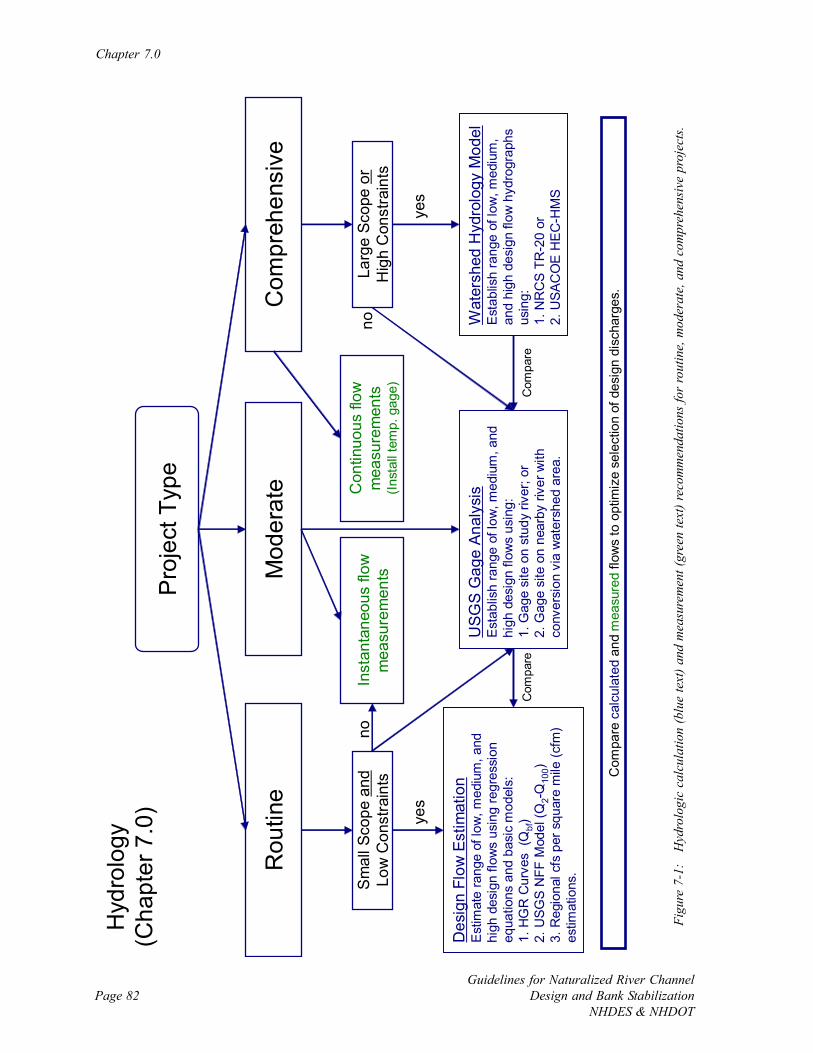
Chapter 7.0
Guidelines for Naturalized River ChannelDesign and Bank Stabilization
NHDES & NHDOTPage 82
Pro
ject
Typ
e
Mod
erat
eR
outin
eC
ompr
ehen
sive
Hyd
rolo
gy(C
hapt
er 7
.0) yes
Sm
all S
cope
and
Low
Con
stra
ints
Larg
e Sc
ope
orH
igh
Con
stra
ints
Com
pare
cal
cula
ted
and
mea
sure
dflo
ws
to o
ptim
ize
sele
ctio
n of
des
ign
disc
harg
es.
no
yes
noIn
stan
tane
ous
flow
m
easu
rem
ents
Con
tinuo
us fl
ow
mea
sure
men
ts
(Inst
all t
emp.
gag
e)
Des
ign
Flow
Est
imat
ion
Est
imat
e ra
nge
of lo
w, m
ediu
m, a
nd
high
des
ign
flow
s us
ing
regr
essi
on
equa
tions
and
bas
ic m
odel
s:1.
HG
R C
urve
s (Q
bf)
2. U
SGS
NFF
Mod
el (Q
2-Q
100)
3. R
egio
nal c
fs p
er s
quar
e m
ile (c
fm)
estim
atio
ns.
USG
S G
age
Anal
ysis
Est
ablis
h ra
nge
of lo
w, m
ediu
m, a
nd
high
des
ign
flow
s us
ing:
1. G
age
site
on
stud
y riv
er; o
r2.
Gag
e si
te o
n ne
arby
rive
r with
co
nver
sion
via
wat
ersh
ed a
rea.
Wat
ersh
ed H
ydro
logy
Mod
elE
stab
lish
rang
e of
low
, med
ium
, an
d hi
gh d
esig
n flo
w h
ydro
grap
hs
usin
g:1.
NR
CS
TR
-20
or
2. U
SAC
OE
HE
C-H
MS
Com
pare
Com
pare
Figu
re 7
-1:
Hyd
rolo
gic
calc
ulat
ion
(blu
e te
xt) a
nd m
easu
rem
ent (
gree
n te
xt) r
ecom
men
datio
ns fo
r ro
utin
e, m
oder
ate,
and
com
preh
ensi
ve p
roje
cts.
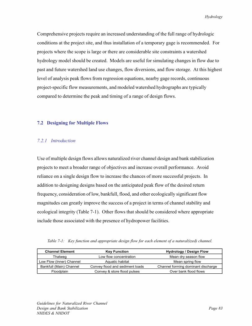
Hydrology
Guidelines for Naturalized River ChannelDesign and Bank StabilizationNHDES & NHDOT
Page 83
Channel Element Key Function Hydrology / Design FlowThalweg Low flow concentration Mean dry season flow
Low Flow (Inner) Channel Aquatic habitat Mean spring flowBankfull (Main) Channel Convey flood and sediment loads Channel forming dominant discharge
Floodplain Convey & store flood pulses Over bank flood flows
Table 7-1: Key function and appropriate design flow for each element of a natural(ized) channel.
Comprehensive projects require an increased understanding of the full range of hydrologic
conditions at the project site, and thus installation of a temporary gage is recommended. For
projects where the scope is large or there are considerable site constraints a watershed
hydrology model should be created. Models are useful for simulating changes in flow due to
past and future watershed land use changes, flow diversions, and flow storage. At this highest
level of analysis peak flows from regression equations, nearby gage records, continuous
project-specific flow measurements, and modeled watershed hydrographs are typically
compared to determine the peak and timing of a range of design flows.
7.2 Designing for Multiple Flows
7.2.1 Introduction
Use of multiple design flows allows naturalized river channel design and bank stabilization
projects to meet a broader range of objectives and increase overall performance. Avoid
reliance on a single design flow to increase the chances of more successful projects. In
addition to designing designs based on the anticipated peak flow of the desired return
frequency, consideration of low, bankfull, flood, and other ecologically significant flow
magnitudes can greatly improve the success of a project in terms of channel stability and
ecological integrity (Table 7-1). Other flows that should be considered where appropriate
include those associated with the presence of hydropower facilities.
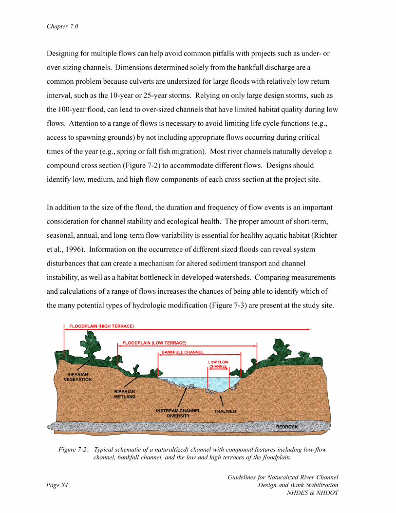
Chapter 7.0
Guidelines for Naturalized River ChannelDesign and Bank Stabilization
NHDES & NHDOTPage 84
BANKFULL CHANNEL
INSTREAM CHANNELDIVERSITY
THALWEG
LOW FLOWCHANNEL
RIPARIANWETLAND
BEDROCK
RIPARIANVEGETATION
FLOODPLAIN (HIGH TERRACE)
FLOODPLAIN (LOW TERRACE)
Figure 7-2: Typical schematic of a natural(ized) channel with compound features including low-flowchannel, bankfull channel, and the low and high terraces of the floodplain.
Designing for multiple flows can help avoid common pitfalls with projects such as under- or
over-sizing channels. Dimensions determined solely from the bankfull discharge are a
common problem because culverts are undersized for large floods with relatively low return
interval, such as the 10-year or 25-year storms. Relying on only large design storms, such as
the 100-year flood, can lead to over-sized channels that have limited habitat quality during low
flows. Attention to a range of flows is necessary to avoid limiting life cycle functions (e.g.,
access to spawning grounds) by not including appropriate flows occurring during critical
times of the year (e.g., spring or fall fish migration). Most river channels naturally develop a
compound cross section (Figure 7-2) to accommodate different flows. Designs should
identify low, medium, and high flow components of each cross section at the project site.
In addition to the size of the flood, the duration and frequency of flow events is an important
consideration for channel stability and ecological health. The proper amount of short-term,
seasonal, annual, and long-term flow variability is essential for healthy aquatic habitat (Richter
et al., 1996). Information on the occurrence of different sized floods can reveal system
disturbances that can create a mechanism for altered sediment transport and channel
instability, as well as a habitat bottleneck in developed watersheds. Comparing measurements
and calculations of a range of flows increases the chances of being able to identify which of
the many potential types of hydrologic modification (Figure 7-3) are present at the study site.
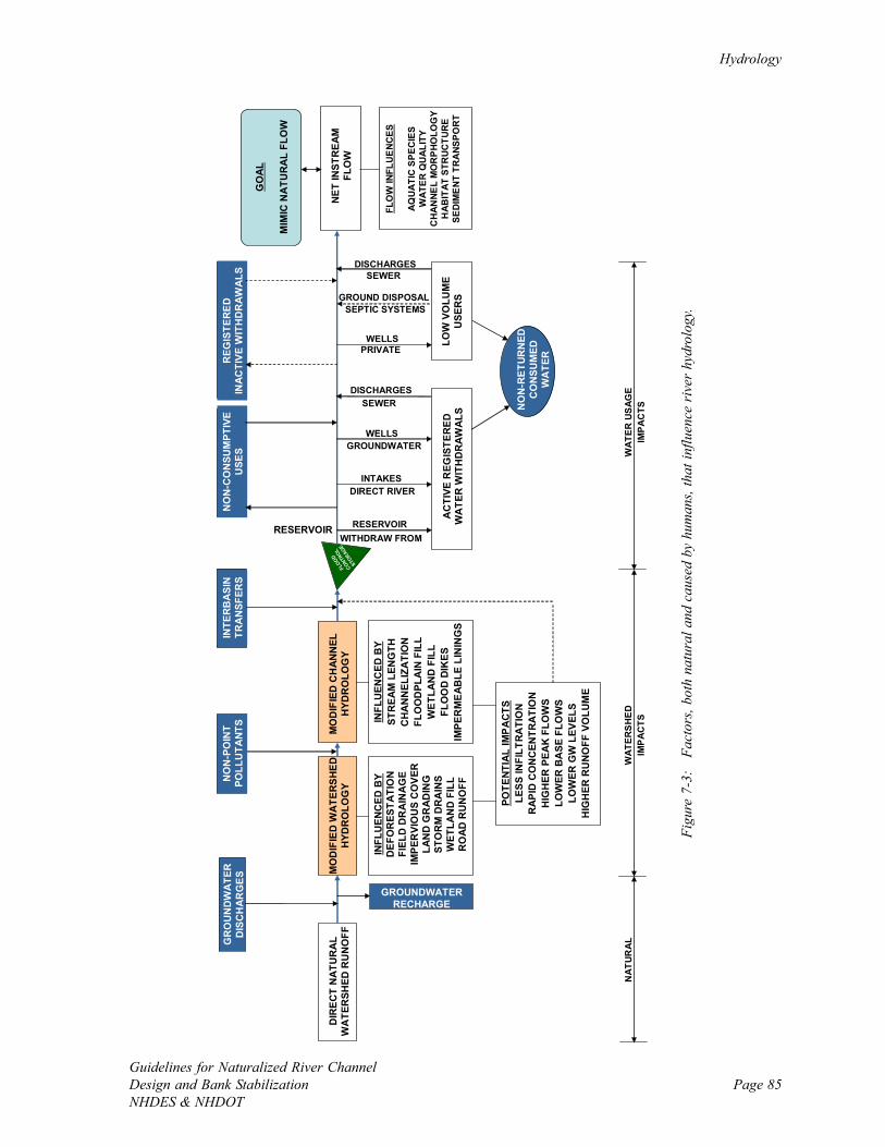
Hydrology
Guidelines for Naturalized River ChannelDesign and Bank StabilizationNHDES & NHDOT
Page 85
DIR
ECT
NAT
UR
AL
WA
TER
SHED
RU
NO
FF
GROUNDWATERRECHARGE
MO
DIF
IED
WA
TER
SHED
HYD
RO
LOG
Y
INFL
UEN
CED
BY
DEF
OR
ESTA
TIO
NFI
ELD
DR
AIN
AG
EIM
PER
VIO
US
CO
VER
LAN
D G
RAD
ING
STO
RM
DR
AIN
SW
ETLA
ND
FIL
LR
OAD
RU
NO
FF
MO
DIF
IED
CH
ANN
ELH
YDR
OLO
GY
INFL
UEN
CED
BY
STR
EAM
LEN
GTH
CH
AN
NEL
IZA
TIO
NFL
OO
DPL
AIN
FIL
LW
ETLA
ND
FIL
LFL
OO
D D
IKES
IMPE
RM
EAB
LE L
ININ
GS
GR
OU
ND
WA
TER
DIS
CH
AR
GES
NO
N-P
OIN
TPO
LLU
TANT
S
FLOOD
CONT
ROL
STORAG
E
INTE
RB
ASI
NTR
AN
SFER
S
POTE
NTIA
L IM
PAC
TSLE
SS IN
FILT
RA
TIO
NR
APID
CO
NC
ENTR
ATIO
NH
IGH
ER P
EAK
FLO
WS
LOW
ER B
ASE
FLO
WS
LOW
ER G
W L
EVEL
SH
IGH
ER R
UN
OFF
VO
LUM
E
NET
INST
REA
MFL
OW
AC
TIVE
REG
ISTE
RED
WA
TER
WIT
HD
RAW
ALS
RESERVOIRWITHDRAW FROM
RESERVOIR
DIRECT RIVERINTAKES
GROUNDWATERWELLS
LOW
VO
LUM
EU
SER
S
DISCHARGES
PRIVATEWELLS
SEPTIC SYSTEMSGROUND DISPOSAL
NO
N-C
ON
SUM
PTIV
EU
SES
REG
ISTE
RED
INAC
TIVE
WIT
HD
RAW
ALS
NO
N-R
ETUR
NED
CO
NSU
MED
WA
TER
NAT
UR
AL
WAT
ERS
HED
IMP
AC
TSW
ATER
US
AGE
IMP
AC
TS
SEWER
DISCHARGESSEWER
FLO
W IN
FLU
EN
CES
AQ
UA
TIC
SPE
CIE
SW
ATER
QU
ALI
TYC
HA
NN
EL
MO
RP
HO
LOG
YH
AB
ITAT
STR
UC
TUR
ESE
DIM
EN
T TR
AN
SPO
RT
GO
AL
MIM
IC N
ATU
RA
L FL
OW
Figu
re 7
-3:
Fac
tors
, bot
h na
tura
l and
cau
sed
by h
uman
s, th
at in
fluen
ce r
iver
hyd
rolo
gy.
Chapter 7.0
Guidelines for Naturalized River ChannelDesign and Bank Stabilization
NHDES & NHDOTPage 86
7.2.2 High Flow
The traditional approach to single-discharge design of river channel and bank stabilization
projects is based on the peak 100-year discharge (Q100) due to the common goal of flood
mitigation and regulation of the 100-year floodplain by the FEMA. While effective at sizing
projects for large floods, many designs that only consider the peak 100-year flow have little
useable aquatic habitat during moderate and low flows due to shallow flow depths, and over-
sized channel and bank materials. Understanding project performance during high flow is
typically required by federal and state government agencies to ensure that flood elevations are
not increased as a result of implementation. High discharge designs should always be used in
conjunction with designs considering other flow levels.
7.2.3 Bankfull Flow
Bankfull flow (Qbf), which takes place approximately once every one to two years, has
become a popular design discharge due to its importance in determining the dimensions of
meandering channels (Wolman and Miller, 1960). Bankfull flow in New Hampshire has been
found to be best approximated by the flood that takes place every 1.5 years (Q1.5), especially
for smaller and steeper river channels (NHST, 2005). The widespread use of bankfull flow in
naturalized river channel design and bank stabilization projects follows the increasing
popularity of dominant discharge – one flow is most responsible for creating stable channel
morphology (FISRWG, 1998). The dominant discharge is used as a surrogate to describe the
flow that transports the most sediment over the long term, or the effective discharge (See
discussion in Schiff et al., 2006). The bankfull flow is an approximation for a single design
discharge and thus it is important to consider additional design discharges.
7.2.4 Ecologically Significant Flows
Based on the species present, variability of flows should be considered during design to
address habitat conditions during the year when important life cycle functions are taking place
Hydrology
Guidelines for Naturalized River ChannelDesign and Bank StabilizationNHDES & NHDOT
Page 87
such as migration and spawning, for example. The Natural Flow Regime (Poff et al., 1997)
suggests that maintaining the natural flow variability that supports habitats for native species
are the key to sustaining ecosystem functions. This concept states that flood flows and
drought conditions are both important to sustaining the ecosystem. Investigate at a minimum
the monthly median and range of flows. Design should accommodate the entire range of
flows so that habitat availability is maintained across this range.
If no gage data are present, regression equations can be used to determine flows, and
compared to surrogate flow data from a similar river. Surrogate flow data should be selected
from rivers where watershed area, slope, elevation and climate conditions are similar.
Translation of gaged flow values into flow per square mile of watershed area (cubic feet per
second per square mile or cfsm) allows for translation of the gaged flows to an ungaged
location of a different watershed size. This translation should be limited to target watersheds
ranging from 0.3 to 1.5 times the gaged watershed area (Ries and Friesz, 2000). Methods are
also available through the US Geological Survey (USGS) for extending partial surrogate gage
records of rivers with similar watershed area, slope, elevation, and climate conditions.
7.2.4.1 Bankfull Flow
Habitat availability is largely a function of channel form and substrate material. Every flow
that transports sediment affects channel form. Maximum sediment transport usually occurs at
relatively moderate flow events rather than large flow events since moderate flows occur
much more frequently than larger events (Wolman and Miller, 1960). The dominant discharge
is used as a surrogate to describe the flow that over the long term transports the most
sediment, or the effective discharge (See discussion in Schiff et al., 2006).
In channels at or near dynamic equilibrium, the dominant discharge is approximately equal to
the bankfull flow (Leopold et al., 1964). Bankfull flow (Qbf) is approximately the flow that
occurs once every one to two years (Q1.5). Bankfull flow has become a popular design
discharge due to its importance in determining the stable dimensions of meandering channels.
Chapter 7.0
Guidelines for Naturalized River ChannelDesign and Bank Stabilization
NHDES & NHDOTPage 88
Although a river channel restored using a design based on bankfull flow is likely to achieve a
dynamic equilibrium, it is important to consider other design discharges such as peak and low
flows.
7.2.4.2 Low Flow
Channel design for low flow conditions should attempt to provide habitat that is similar to the
natural low flow condition. Low flows have important ecologic functions. Low flows are
naturally occurring conditions that native species are adapted to withstand when natural
habitat conditions are present to provide refuge. Non-native species may be restricted by low
flow conditions. During low flows aquatic habitat quality and abundance is often reduced and
higher flow dependent organisms experience stressed living conditions. Limited access to
food and refuge areas is common during low flows as connectivity between suitable habitats is
reduced or eliminated and fragmentation occurs. Increased water temperature and reduced
dissolved oxygen harms coldwater species. These effects on higher-flow dependent species
are balanced by improved conditions for other species such as invertebrates and oppressive
conditions for invasive species. Naturally occurring low flows should not be prevented, but
channel design for low flow conditions should strive to provide habitat availability, abundance,
and connectivity similar to natural reaches. Low flow statistics have been developed for New
Hampshire (Flynn, 2003) and are available on the Internet (http://pubs.usgs.gov/wri/wri02-
4298/).
Establishing conditions that result in dynamic equilibrium may play the largest role in the
maintaining availability of habitat during low flows. A constructed low flow habitat that has
been poorly designed is unlikely to persist. Low flow habitat is likely to occupy the deepest
part of the river channel, or thalweg. As such it may be subject to sediment deposition
following floods. It may not be possible to construct permanent habitat for low flow
conditions, but it should be possible to design the channel such that its slope, width, depth,
and substrate material will continue to recreate low flow habitat. Appropriate design
parameters will take into consideration substrate material and channel competence, the
Hydrology
Guidelines for Naturalized River ChannelDesign and Bank StabilizationNHDES & NHDOT
Page 89
maximum size particle that a river can transport at a given flow, when determining channel
slope, width and depth. The bankfull flow may be used to identify the minimum size substrate
that will remain stable at flows up to the bankfull flow, which is the most frequent sediment
transport flow. Particles larger than the channel competence size at this flow can be used to
create more permanent refuge for fish, but flows higher than bankfull flows may dislodge even
these. Large particles will increase channel roughness and thereby slow average water
velocity and increase depth. The tradeoffs between parameters like depth and temperature
change with increased channel roughness should be evaluated.
7.3 Flow Measurement
7.3.1 Introduction
Flow measurements are recommended for all but routine projects that are both small in scope
and have low site constraints. Instantaneous flow measurements at cross sections are
recommended for more involved routine projects and moderate projects to get a snapshot of
current baseflow conditions. These measurements are used to check calculations (routine
projects) and for gage analysis (moderate and comprehensive projects), and offer a current
point of reference during baseflow conditions.
Installation of a staff gage is recommended in the event that flow measurements are desired
during frequent regular visits to the project site. In this case, between five and ten flow
measurements are made at the cross section over a range of flow levels and a depth-discharge
rating curve is established. Flow can then be readily obtained by simply recording the gage
reading on the depth and conversion using the rating curve. This approach to flow monitoring
is particularly appealing if long-term monitoring is planned since no instrumentation is needed
once the rating curve is created.
Chapter 7.0
Guidelines for Naturalized River ChannelDesign and Bank Stabilization
NHDES & NHDOTPage 90
Installation of a temporary continuously monitoring gage is recommended for comprehensive
projects. This procedure requires installation of a pressure probe to record water depth and
five to ten instantaneous flow measurements at the cross section during various flow
conditions to create a rating curve to convert depth to discharge. If a total station survey is
planned for the project, survey the probe installation so that depths can be converted to water
surface elevations.
7.3.2 Instantaneous Flow Measurements
Instantaneous flow at a cross section is most commonly measured via the velocity-area-integration method (Roberson et al., 1988). The channel cross section is divided into flow
cells, and in each cell the depth is recorded and water velocity is measured using a current
velocity meter. USGS recommends measuring the velocity at 0.6 times the water depth for
shallow flows (depth < 2.5 feet), while the velocity in deeper flows is the mean of
measurements at 0.2 and 0.8 times the depth. The flow through each segment in the cross
section is determined via the continuity equation (Q=VA where Q is discharge (cfs), V is
velocity (fps) and A is cross sectional area (sq ft)). Finally, the flow in each cell is added to
obtain the total flow at the cross section (QT=ΣQi=ΣViAi).
Installing a staff gage and developing a rating curve (Leopold, 1994) is an efficient and
economical approach to making many (> 10) repeated flow measurements. After firmly
pounding a staff gage into the river bed, between five and ten instantaneous flow
measurements are made over time at the cross section during a range of low, medium, and
high flows. During each measurement the gage reading is recorded so that a relationship
between the gage and discharge is established – the rating curve of that staff gage (Dunne and
Leopold, 1978). Once the rating curve is established, flow measurements can readily be
determined from reading the gage and converting to flow as long as the gage remains in its
original location and the channel cross section remains stable.
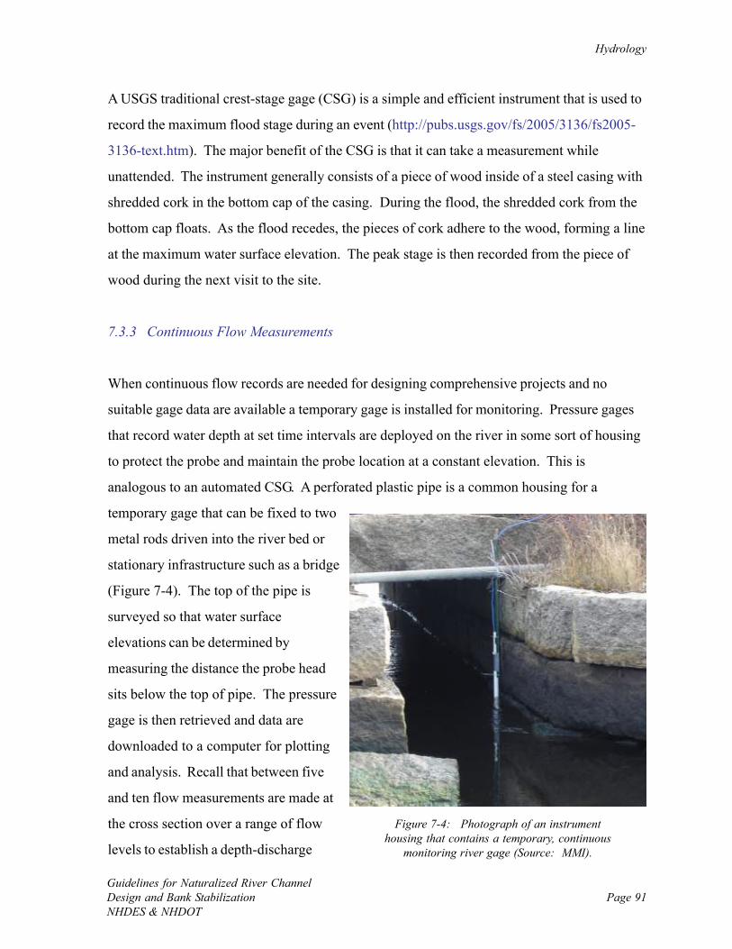
Hydrology
Guidelines for Naturalized River ChannelDesign and Bank StabilizationNHDES & NHDOT
Page 91
Figure 7-4: Photograph of an instrumenthousing that contains a temporary, continuous
monitoring river gage (Source: MMI).
A USGS traditional crest-stage gage (CSG) is a simple and efficient instrument that is used to
record the maximum flood stage during an event (http://pubs.usgs.gov/fs/2005/3136/fs2005-
3136-text.htm). The major benefit of the CSG is that it can take a measurement while
unattended. The instrument generally consists of a piece of wood inside of a steel casing with
shredded cork in the bottom cap of the casing. During the flood, the shredded cork from the
bottom cap floats. As the flood recedes, the pieces of cork adhere to the wood, forming a line
at the maximum water surface elevation. The peak stage is then recorded from the piece of
wood during the next visit to the site.
7.3.3 Continuous Flow Measurements
When continuous flow records are needed for designing comprehensive projects and no
suitable gage data are available a temporary gage is installed for monitoring. Pressure gages
that record water depth at set time intervals are deployed on the river in some sort of housing
to protect the probe and maintain the probe location at a constant elevation. This is
analogous to an automated CSG. A perforated plastic pipe is a common housing for a
temporary gage that can be fixed to two
metal rods driven into the river bed or
stationary infrastructure such as a bridge
(Figure 7-4). The top of the pipe is
surveyed so that water surface
elevations can be determined by
measuring the distance the probe head
sits below the top of pipe. The pressure
gage is then retrieved and data are
downloaded to a computer for plotting
and analysis. Recall that between five
and ten flow measurements are made at
the cross section over a range of flow
levels to establish a depth-discharge
Chapter 7.0
Guidelines for Naturalized River ChannelDesign and Bank Stabilization
NHDES & NHDOTPage 92
rating curve to convert water depths to flow measurements. It is useful to obtain local
precipitation data to help with the interpretation of the gage data. Typical analyses include
determining peak, timing, and shape of storm hydrographs, as well as trends in baseflow.
7.4 Design Flow Estimation
7.4.1 Introduction
For all projects, begin with design flow estimation using regression equations, basic models,
and regional estimations. These tools offer a quick way to determine the flow at the project
site with limited site information. For routine projects that are small in scope and have low
constraints, the basic estimations are often adequate for design. For most projects, however,
the estimations are compared to flow statistics from measurements, a gage analysis or a
watershed hydrology model.
7.4.2 Hydraulic Geometry Relationships
Hydraulic geometry relationships (HGR) are empirically-derived power relationships that are
useful for rapidly estimating discharge at a given return frequency, water velocity, channel
width, depth, or cross sectional area as a function of watershed area (Leopold and Maddock,
1953). The State of New Hampshire currently has provisional HGR curves that include the
relationship between watershed area (sq mi) and Qbf (cfs) (Figure 7-5). Note that the New
Hampshire curves are slightly skewed towards smaller river channels in steeper terrain as a
result of including data from channels in the White Mountains to create the curves. For larger
rivers such as those in the Connecticut River Basin, it is more appropriate to use Vermont’s
HGR curves (Appendix J in VTANR, 2005) to determine bankfull flow. It is typically useful
to compare HGR calculations with results from other empirical studies in nearby states or
other regions (Dunne and Leopold, 1978).
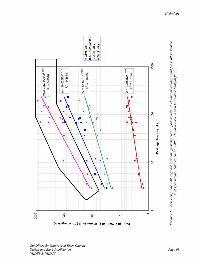
Hydrology
Guidelines for Naturalized River ChannelDesign and Bank StabilizationNHDES & NHDOT
Page 93
Qbk
f = 4
4.15
9DA
0.91
14
R2 =
0.8
046
A =
16.0
24D
A0.75
52
R2 =
0.8
673
W =
12.
469D
A0.
4892
R2 =
0.8
208
D =
1.2
952D
A0.26
45
R2 =
0.7
903
110100
1000
1000
0
110
100
1000
Dra
inag
e Ar
ea (s
q.m
i.)
Depth (ft.) / Width (ft.) / XS Area (sq.ft.) / Discharge (cfs)
Qbk
f (cf
s)XS
Are
a (s
q.ft.
)W
idth
(ft.)
Dep
th (f
t.)
Figu
re 7
-5:
New
Ham
pshi
re 2
005
regi
onal
hyd
raul
ic g
eom
etry
cur
ves
(pro
visi
onal
), w
hich
are
par
ticul
arly
use
ful f
or s
mal
ler
chan
nels
in s
teep
er te
rrai
n (S
ourc
e: N
HST
, 200
5).
Out
lined
cur
ve is
use
d to
est
imat
e ba
nkfu
ll flo
w.
Chapter 7.0
Guidelines for Naturalized River ChannelDesign and Bank Stabilization
NHDES & NHDOTPage 94
7.4.3 National Flood Frequency Model
The National Flood Frequency Program (NFF) provides regression-equation estimates of
peak discharges for unregulated rural and urban watersheds, flood-frequency plots, and plots
of typical flood hydrographs for selected recurrence intervals for every state in the US The
Program also provides weighting techniques to improve estimates of flood-peak discharges
for gauging stations and ungaged sites (Ries and Crouse, 2002).
The NFF model for the State of New Hampshire allows for calculation of peak flows of
storms with recurrence intervals of 2, 5, 10, 25, 50, and 100 years (LeBlanc, 1978). Inputs
into the model include watershed area (sq mi), channel slope (ft/mi), and the 2-year, 24-hour
precipitation (in). A detailed description of the New Hampshire NFF model and a map of the
2-year, 24-hour precipitation is presented in Appendix D. The NFF model can be downloaded
from the Internet (http://water.usgs.gov/software/nff.html).
Note that the NFF regression equations for New Hampshire were established in 1978. With
30 years of additional flow data collected since then, the equations are outdated and in their
current form are recommended as a rough approximation of peak flows and a source of data
for comparison to other design flow estimations. USGS and New Hampshire Department of
Transportation may be updating the regression equations in the near future so check the NNF
website listed above for more recent information.
7.4.4 Regional Approximations
Regional approximations of the amount of flow for the given watershed area (cfsm) are useful
guides to verify other estimates of design flows and help guide calculations and design.
Relationships exist to estimate of a variety of flow scenarios for the northeast US (Table 7-2).
A previous analysis of river gages in New England has also led to establishment of a generic
hydrograph (cfsm versus month) that also can be used for gaining a rough estimate of typical
seasonal flows (Figure 7-6) (Lang, 1999).
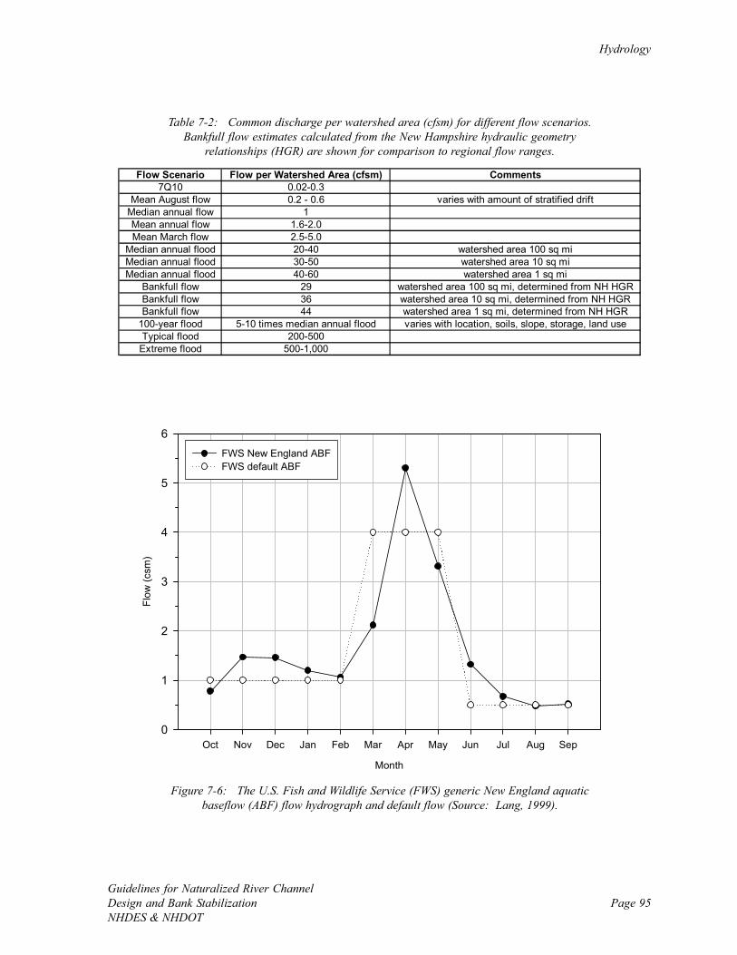
Hydrology
Guidelines for Naturalized River ChannelDesign and Bank StabilizationNHDES & NHDOT
Page 95
Flow Scenario Flow per Watershed Area (cfsm) Comments7Q10 0.02-0.3
Mean August flow 0.2 - 0.6 varies with amount of stratified driftMedian annual flow 1Mean annual flow 1.6-2.0Mean March flow 2.5-5.0
Median annual flood 20-40 watershed area 100 sq miMedian annual flood 30-50 watershed area 10 sq miMedian annual flood 40-60 watershed area 1 sq mi
Bankfull flow 29 watershed area 100 sq mi, determined from NH HGRBankfull flow 36 watershed area 10 sq mi, determined from NH HGRBankfull flow 44 watershed area 1 sq mi, determined from NH HGR
100-year flood 5-10 times median annual flood varies with location, soils, slope, storage, land useTypical flood 200-500
Extreme flood 500-1,000
Table 7-2: Common discharge per watershed area (cfsm) for different flow scenarios.Bankfull flow estimates calculated from the New Hampshire hydraulic geometry
relationships (HGR) are shown for comparison to regional flow ranges.
Figure 7-6: The U.S. Fish and Wildlife Service (FWS) generic New England aquaticbaseflow (ABF) flow hydrograph and default flow (Source: Lang, 1999).
Month
Oct Nov Dec Jan Feb Mar Apr May Jun Jul Aug Sep
Flow
(csm
)
0
1
2
3
4
5
6FWS New England ABFFWS default ABF
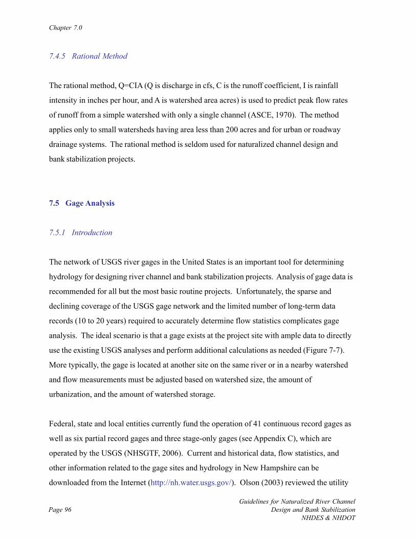
Chapter 7.0
Guidelines for Naturalized River ChannelDesign and Bank Stabilization
NHDES & NHDOTPage 96
7.4.5 Rational Method
The rational method, Q=CIA (Q is discharge in cfs, C is the runoff coefficient, I is rainfall
intensity in inches per hour, and A is watershed area acres) is used to predict peak flow rates
of runoff from a simple watershed with only a single channel (ASCE, 1970). The method
applies only to small watersheds having area less than 200 acres and for urban or roadway
drainage systems. The rational method is seldom used for naturalized channel design and
bank stabilization projects.
7.5 Gage Analysis
7.5.1 Introduction
The network of USGS river gages in the United States is an important tool for determining
hydrology for designing river channel and bank stabilization projects. Analysis of gage data is
recommended for all but the most basic routine projects. Unfortunately, the sparse and
declining coverage of the USGS gage network and the limited number of long-term data
records (10 to 20 years) required to accurately determine flow statistics complicates gage
analysis. The ideal scenario is that a gage exists at the project site with ample data to directly
use the existing USGS analyses and perform additional calculations as needed (Figure 7-7).
More typically, the gage is located at another site on the same river or in a nearby watershed
and flow measurements must be adjusted based on watershed size, the amount of
urbanization, and the amount of watershed storage.
Federal, state and local entities currently fund the operation of 41 continuous record gages as
well as six partial record gages and three stage-only gages (see Appendix C), which are
operated by the USGS (NHSGTF, 2006). Current and historical data, flow statistics, and
other information related to the gage sites and hydrology in New Hampshire can be
downloaded from the Internet (http://nh.water.usgs.gov/). Olson (2003) reviewed the utility
Hydrology
Guidelines for Naturalized River ChannelDesign and Bank StabilizationNHDES & NHDOT
Page 97
AD
JUST
FO
RW
ATE
RSH
EDSI
ZE
AD
JUST
FO
RU
RB
AN
IZA
TIO
N
AD
JUST
FO
RST
OR
AG
E
AD
JUST
FO
RW
ATE
RSH
EDSI
ZE
AD
JUST
FO
RU
RBA
NIZ
ATI
ON
AD
JUST
FO
RST
OR
AG
E
REV
IEW
WA
TERS
HED
STA
BIL
ITY
, HIS
TOR
YA
DJU
ST P
ERIO
D O
F RE
CORD
PER
FO
RM F
REQ
UEN
CY
AN
ALY
SIS
GA
GED
AT
SIM
ILA
RW
ATE
RSH
EDN
EAR
BY
GA
GED
AT
POIN
T O
FIN
TER
EST
GA
GED
AT
AN
OTH
ERSI
TE O
N S
AM
EST
REA
M
USE
EX
ISTI
NG
USG
SFR
EQU
ENCY
AN
ALY
SIS
BES
T FI
T O
FSI
MIL
AR
WA
TER
SHED
S
SELE
CT
IND
ICA
TOR
GA
GE
WA
TER
SHED
S
GA
GE
AN
ALY
SIS
WA
TER
SHED
DA
TAA
REA
LAN
D U
SEW
ATE
R S
TOR
AG
E
Figu
re 7
-7:
Flo
w c
hart
sum
mar
izin
g th
e pr
oced
ure
for
gage
ana
lysi
s.
Chapter 7.0
Guidelines for Naturalized River ChannelDesign and Bank Stabilization
NHDES & NHDOTPage 98
of the USGS gage network in New Hampshire and found, as in many other states, that
increased data collection would lead to better estimates of regional flow conditions.
Additional gages are operated in New Hampshire by the Department of Environmental
Services (DES) Dam Bureau and data are accessible via the Internet (http://
www.des.state.nh.us/RTi_Home/).
7.5.2 Gage Located at Project Site
When a USGS gage is located at the project site flow statistics that are directly available from
the Internet can be used to estimate the magnitude of various design flows. Daily, monthly,
annual and peak flow statistics are available for download, and are referenced based on a
water year beginning on October 1 and ending September 30. Low flow statistics are
typically based upon the climatic year of April 1 to March 31. Curves that indicate flow
duration, the percentage of time a given flow was equaled or exceeded over a period of time,
and flow frequency, the chance that a given flow is exceeded in a year, are the main products
of gage analysis (Dunne and Leopold, 1978; Leopold, 1994, 1997; FISRWG, 1998). In
addition, other flow statistics may be investigated such as minima and maxima for a given
number of days and number and duration of high and low flow pulses that are important to the
ecological integrity of the river system (Richter et al., 1996; Richter et al., 1998).
7.5.3 Gage Located at Nearby Site or Neighboring Watershed
If a gage exists on the same river as the project site or in a neighboring watershed, a surrogate
gage may be used following a comparison of watershed size, the degree of urbanization, and
the amount of storage is required. For the surrogate gage watershed, area within 50%,
comparable amounts of urbanization, and similar storage is preferred. In this case flow
measurements need only be scaled based on differences in area. If required, peak runoff
estimates can be adjusted by a correction factor for watershed storage and impervious cover
(Leopold, 1968).
Hydrology
Guidelines for Naturalized River ChannelDesign and Bank StabilizationNHDES & NHDOT
Page 99
Correlating flow measurements at a project site to flows at a nearby gage is another useful
technique for estimating design flows. If a correlation exists, flows and flow statistics can be
estimated at the project site using the USGS technique called MOVE.1 (Nielsen, 1999). This
method works well with lower flows, base flows, or when flows are fairly steady at
unregulated sites. Although more time intensive, a correlation method will provide better
results than the simple scaling of drainage area.
7.6 Watershed Hydrology Models
7.6.1 Introduction
For naturalized river channel design and bank stabilization projects in ungaged watersheds
that are large in scope or have high site constraints, a watershed hydrology model is
recommended to obtain a range of design flows and hydrographs. The Natural Resource
Conservation Service (NRCS), formerly known as the Soil Conservation Service (SCS), curve
number method (Dingman, 1994) is the most popular means of modeling storm hydrographs.
The Computer Program for Project Formulation Hydrology (TR-20) (SCS, 1992) and the
Hydrologic Modeling System (HEC-HMS) (USACOE, 2001) are two computer models that
are commonly used to perform hydrologic modeling.
7.6.2 TR-20
TR-20 is a physically based watershed runoff model that computes runoff and develops unit
hydrographs from synthetic or natural precipitation. Developed hydrographs can be routed
through reaches, storage areas and structures. The most recent version of the program and
documentation can be obtained from the Internet (http://www.wcc.nrcs.usda.gov/hydro/
hydro-tools-models-tr20.html). Many manuals, tables, and worksheets are also readily
available to assist with each step of the TR-20 modeling procedure. The current version of
Chapter 7.0
Guidelines for Naturalized River ChannelDesign and Bank Stabilization
NHDES & NHDOTPage 100
TR-20 is a Windows-based application, while previous versions that are still widely used have
text input/output files.
Area, soil types, and land use are determined to establish a curve number for each
subwatershed. The curve number is then weighted by area to calculate a composite curve
number for the entire watershed. The travel time in each subwatershed is determined based
on the presence of sheet flow, shallow concentrated flow, and channel flow, and then each is
added to get the time of concentration that represents the longest possible flow path through
the watershed. Stage-storage-discharge relationships are needed for each reservoir or struc-
ture that stores water. If precipitation data are not available, estimates for the eastern United
States are typically obtained from the National Weather Service Rainfall Frequency Atlas
(Hershfield, 1961) to simulate the storm event. Antecedent moisture condition is input to
estimate the infiltration capacity of the soil. Outputs from TR-20 include the size and timing
of the peak flow as well as the full flood hydrograph.
Note that TR-55 (SCS, 1986) is a simplified version of TR-20 that enables a rapid manual or
interactive desktop solution of peak flows in urban watersheds. Because its use is limited to
watersheds having areas less than 2,000 acres and homogenous runoff conditions, TR-55 is
rarely used for naturalized channel design and bank stabilization projects.
7.6.3 HEC-HMS
HEC-HMS is the US Army Corps of Engineer’s version of a physical watershed hydrologic
modeling program. This Windows-based program replaced the Flood Hydrograph Package
(HEC-1) (USACOE, 1990) and is a graphical means of representing a dendritic network to
simulate runoff processes. Model elements include subwatersheds, reach, junction, reservoir,
diversion, source, and sink. The SCS Curve Number Method is commonly used when
performing hydrology modeling with HEC-HMS, yet some other options are available for unit
hydrograph calculation. The most recent version of the program and full documentation can
be obtained via the Internet (http://www.hec.usace.army.mil/software/hec-hms/).
Page 101Guidelines for Naturalized River ChannelDesign and Bank StabilizationNHDES & NHDOT
CHAPTER 8.0: GEOMETRIC DESIGN CONCEPTS
8.1 Introduction
Naturalized channel design and bank stabilization projects are planned in order to create a
river that has adequate hydraulic capacity, is dynamic over the short term yet stable over the
long-term periods, has good aquatic habitat, and is an attractive community asset. The project
classification system described in Section 2.0 of this report is used prior to design to establish
project goals and what type of channel is to be considered.
Valley and cross section measurements are taken to inform project design, and the level of
detail of the measurements is primarily a function of whether a project is routine, moderate or
comprehensive (Figure 8-1). For simple routine projects such as local bank stabilization or
small culvert installations, geometric design can consist of a few site measurements with a
tape measure and basic calculations. For comprehensive projects on the other hand, detailed
project design could require an extended cross section survey at the reach scale and
topographic mapping across the floodplain on the valley floor. Design procedure is also
influenced by whether the channel is going to be a non-alluvial rigid boundary channel or an
alluvial channel (Table 8-1).
This chapter discusses specific concepts to establish the size, shape, and pattern of the channel
and floodplain for naturalized river channel and bank stabilization projects. This step in the
design sequence follows the review of the initial assessment data that is used to generally
understand the hydrology and hydraulics, sediment transport characteristics, and channel
morphology of the river. In addition, channel and bank management techniques are presented
to promoted channel stability, create diverse habitats and improve aesthetics.
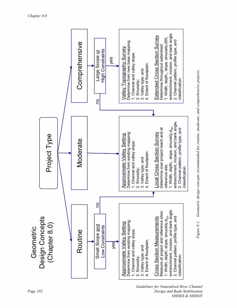
Chapter 8.0
Guidelines for Naturalized River ChannelDesign and Bank Stabilization
NHDES & NHDOTPage 102
Pro
ject
Typ
e
Mod
erat
eR
outin
eC
ompr
ehen
sive
yes
Sm
all S
cope
and
Low
Con
stra
ints
Larg
e Sc
ope
orH
igh
Con
stra
ints
no
yes
no
Geo
met
ricD
esig
n C
once
pts
(Cha
pter
8.0
)
Appr
oxim
ate
Valle
y Se
tting
Det
erm
ine
from
exi
stin
g m
appi
ng:
1. C
hann
el a
nd v
alle
y sl
ope;
2. S
inuo
sity
;3.
Val
ley
type
; and
4. E
xten
t of f
lood
plai
n.
Cro
ss S
ectio
n M
easu
rem
ents
Mea
sure
at p
roje
ct a
nd re
fere
nce
site
s:1.
Wid
th, d
epth
, slo
pe, s
inuo
sity
,d50
, en
trenc
hmen
t, in
cisi
on, a
nd b
ank
angl
e.2.
Cha
nnel
pat
tern
, pro
file
type
, and
cl
assi
ficat
ion.
Appr
oxim
ate
Valle
y Se
tting
Det
erm
ine
from
exi
stin
g m
appi
ng:
1. C
hann
el a
nd v
alle
y sl
ope;
2. S
inuo
sity
;3.
Val
ley
type
; and
4. E
xten
t of f
lood
plai
n.
Loca
l Cro
ss S
ectio
n Su
rvey
Det
erm
ine
over
pro
ject
reac
h an
d at
re
fere
nce
site
:1.
Wid
th, d
epth
,, sl
ope,
sin
uosi
ty,d
50,
entre
nchm
ent,
inci
sion
, and
ban
k an
gle.
2. C
hann
el p
atte
rn, p
rofil
e ty
pe, a
nd
clas
sific
atio
n.
Valle
y To
pogr
aphy
Sur
vey
Det
erm
ine
from
new
bas
e m
appi
ng:
1. C
hann
el a
nd v
alle
y sl
ope;
2. S
inuo
sity
;3.
Val
ley
type
; and
4. E
xten
t of f
lood
plai
n.
Exte
nded
Cro
ss S
ectio
n Su
rvey
Det
erm
ine
thro
ugho
ut w
ater
shed
:1.
Wid
th, d
epth
,, sl
ope,
sin
uosi
ty,d
50,
entre
nchm
ent,
inci
sion
, and
ban
k an
gle.
2. C
hann
el p
atte
rn, p
rofil
e ty
pe, a
nd
clas
sific
atio
n.
Figu
re 8
-1:
Geo
met
ric
desi
gn c
once
pts
reco
mm
ende
d fo
r ro
utin
e, m
oder
ate,
and
com
preh
ensi
ve p
roje
cts.
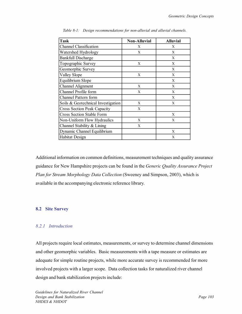
Geometric Design Concepts
Guidelines for Naturalized River ChannelDesign and Bank StabilizationNHDES & NHDOT
Page 103
Task Non-Alluvial AlluvialChannel Classification X XWatershed Hydrology X XBankfull Discharge XTopographic Survey X XGeomorphic Survey XValley Slope X XEquilibrium Slope XChannel Alignment X XChannel Profile form X XChannel Pattern form XSoils & Geotechnical Investigation X XCross Section Peak Capacity XCross Section Stable Form XNon-Uniform Flow Hydraulics X XChannel Stability & Lining XDynamic Channel Equilibrium XHabitat Design X
Table 8-1: Design recommendations for non-alluvial and alluvial channels.
Additional information on common definitions, measurement techniques and quality assurance
guidance for New Hampshire projects can be found in the Generic Quality Assurance Project
Plan for Stream Morphology Data Collection (Sweeney and Simpson, 2003), which is
available in the accompanying electronic reference library.
8.2 Site Survey
8.2.1 Introduction
All projects require local estimates, measurements, or survey to determine channel dimensions
and other geomorphic variables. Basic measurements with a tape measure or estimates are
adequate for simple routine projects, while more accurate survey is recommended for more
involved projects with a larger scope. Data collection tasks for naturalized river channel
design and bank stabilization projects include:
Chapter 8.0
Guidelines for Naturalized River ChannelDesign and Bank Stabilization
NHDES & NHDOTPage 104
1. Define the upstream and downstream project limits;
2. Define the limits of local river reaches – stretches of river with common physical
conditions, such as slope, width, substrate, and bank conditions.
3. Use of a classification system to better understand the channel type;
4. If an alluvial channel is to be designed using analog methods (see Section 9.3), or ifthe project site is extensively disturbed, find a similar stable reference reach;
5. Select the cross section locations to be surveyed at the project and reference sites.
Preferred locations are at the upstream end of a riffle or stable runs. Use pools only if
new pools are to be created. Mark cross section locations for the survey;
6. Identify and flag the bankfull indicators for width and depth at each cross section;
7. Survey the cross sections to record their shape, bankfull indicators, and edge of water
using a long tape and rod, or using professional survey equipment;
8. Survey the river bed profile, riffles, runs, glides, and pools;
9. Survey the channel thalweg and banks to record river alignment and meanders.
10. Measure the size particle distribution of the substrate at cross sections. This may
include pebble counts for course substrate or sieve tests of sandy material.
Collectively, this information documents pre-project conditions and is essential for the design
of stable naturalized channels.
Beyond regional and site location mapping that is part of the initial assessment data (Chapter
3.0), most projects will require a drawing or map of existing site conditions and one or more
drawings of the proposed modifications to be used for project planning, permitting, and
construction. Drawings for routine projects such as bank plantings, bank slope reduction, or
in-channel habitat features may use simple sketches, while moderate and comprehensive
projects and those affecting long reach lengths require detailed professional surveys and plans.
Geometric Design Concepts
Guidelines for Naturalized River ChannelDesign and Bank StabilizationNHDES & NHDOT
Page 105
8.2.2 Site Measurements for Simple Routine Projects
For simple routine projects that are both small in scope and have low site constraints, local
measurement of channel dimensions with a tape measure are usually adequate for design.
Hand-drawn sketches based on field measurements and observations are appropriate when:
• Property boundaries are not needed;
• Utilities are not present;
• Channel fill or excavation does not occur; and
• Channel vulnerability is low.
Typical projects of this type include planting vegetation on river banks and in the riparian
buffer, reducing the slope of the river banks above the water line, and garbage removal (tires,
shopping carts, etc...).
A 100-foot long tape can be used to measure the length and width of the proposed project,
location of the channel banks, channel width, and physical features. A typical cross section of
the channel near the project site is required. This information can be sketched to scale with
reasonable accuracy on graph paper. Basic sketch maps of this type will not have ground
elevations or contour lines.
For simple routine projects, valley setting (i.e., multi-reach slope and sinuosity, valley type,
and floodplain width) can be approximated from mapping collected during the initial
assessment.
8.2.3 Local Survey and Geomorphic Assessment
Local survey in conjunction with a geomorphic assessment is recommended for more involved
routine projects, moderate projects, and comprehensive projects that are not both large in
scope and have high site constraints.
Chapter 8.0
Guidelines for Naturalized River ChannelDesign and Bank Stabilization
NHDES & NHDOTPage 106
Channel cross section dimensions and local river bed slope are determined from the survey in
the vicinity of the project site, and typically over the project reach. If the reference reach
approach is being used, the survey will include a stable reference site. Reference sites,
however, are often not available so empirical and analytical approaches to channel sizing are
used (Chapter 9.0).
The local cross section survey is done in conjunction with a geomorphic assessment. Field
indicators of bankfull water surface elevation (e.g., the top of point bars on the inside of
meanders, the limit of woody vegetation on the banks, and a well-formed bench on the bank
where some sediment deposition is evident) are marked and surveyed. Substrate particle sizes
are determined via a pebble count. A field estimate of the percentage of bed mobility can be
determined by determining the largest particle that appears mobile (i.e., unconsolidated and
clean of aquatic vegetation) on a local depositional feature such as a bar and the percentage
finer than a particle of that size as determined from the pebble count. This measurement is
called the riffle stability index (Kappesser, 2002), and is an indicator of the percentage of the
bed that tends to be mobile during bankfull flows.
Although a range of professionals with specialized training can perform the geomorphic
assessment, it is often helpful to have a licensed land surveyor perform the site survey to geo-
reference the site, prepare detailed plans, and provide accurate horizontal and vertical
coordinate systems that allow use of computer assisted drawing (AutoCAD) and accurate
hydraulic modeling. The field work requires a tripod-mounted level, transit, or theodolite;
plus a stadia rod and 100-foot tape measure.
The rapid field assessment, or Phase 2, of the Vermont Geomorphic Assessment protocols
(http://www.anr.state.vt.us/dec/waterq/rivers/htm/rv_geoassesspro) offers excellent
information on methods and useful field forms to guide data collection. In addition, the
appendices in the Vermont protocols offer valuable background information on a variety of
topics such as channel evolution, channel classification, bridge and culvert assessment,
bankfull indicators, and regional hydraulic geometry curves. Several other references provide
Geometric Design Concepts
Guidelines for Naturalized River ChannelDesign and Bank StabilizationNHDES & NHDOT
Page 107
user-friendly descriptions of how to do a geomorphic assessment (Harrelson et al., 1994;
Rosgen and Silvey, 1996; Doll et al., 2003). Sketches and spreadsheets are useful for data
storage and calculations, and geomorphology-specific spreadsheets (e.g., STREAM Modules:
Spreadsheet Tools for River Evaluation, Assessment and Monitoring - http://
www.dnr.state.oh.us/soilandwater/streammorphology) are available on the Internet.
Ultimately, the above field work is used to determine the mean and range of the channel’s
bankfull widths, depths, riffle and pool geometry, channel slope, percent riffle-run-pool-glide,
particle size distribution, and percent substrate types (cobble, gravel, sand, silt, clay).
For more involved routine projects, moderate projects, and comprehensive projects that are
not both large in scope and have high site constraints, valley setting (i.e., multi-reach slope
and sinuosity, valley type, and floodplain width) can be approximated from mapping collected
during the initial assessment.
8.2.4 Extended Topographic Surveys
Extended cross section surveys over multiple reaches and a full valley topographic survey is
recommended for comprehensive projects that are large in scope or have high constraints.
Topographic surveys present a detailed image of physical features and landscape data that
depict changes in elevation and slope. Land and riverbed elevations may be represented by
both spot elevations and contour lines. Topographic maps may be based upon either ground
surveys or aerial photogrammetric data. The more detailed mapping of the land surface is
particularly important for large sites and those with high degree of site constraints where
flooding and nearby infrastructure protection is a concern.
Data collection needs are the same as for the local survey and geomorphic assessment
described in Section 8.2.3 (e.g., cross sections, profile, bankfull indicators, and hydraulic
features). In addition to contour lines, maps should show buildings, roads, all river channels,
subsurface and aerial utilities, fences, driveways, stone walls, large or isolated trees, bedrock
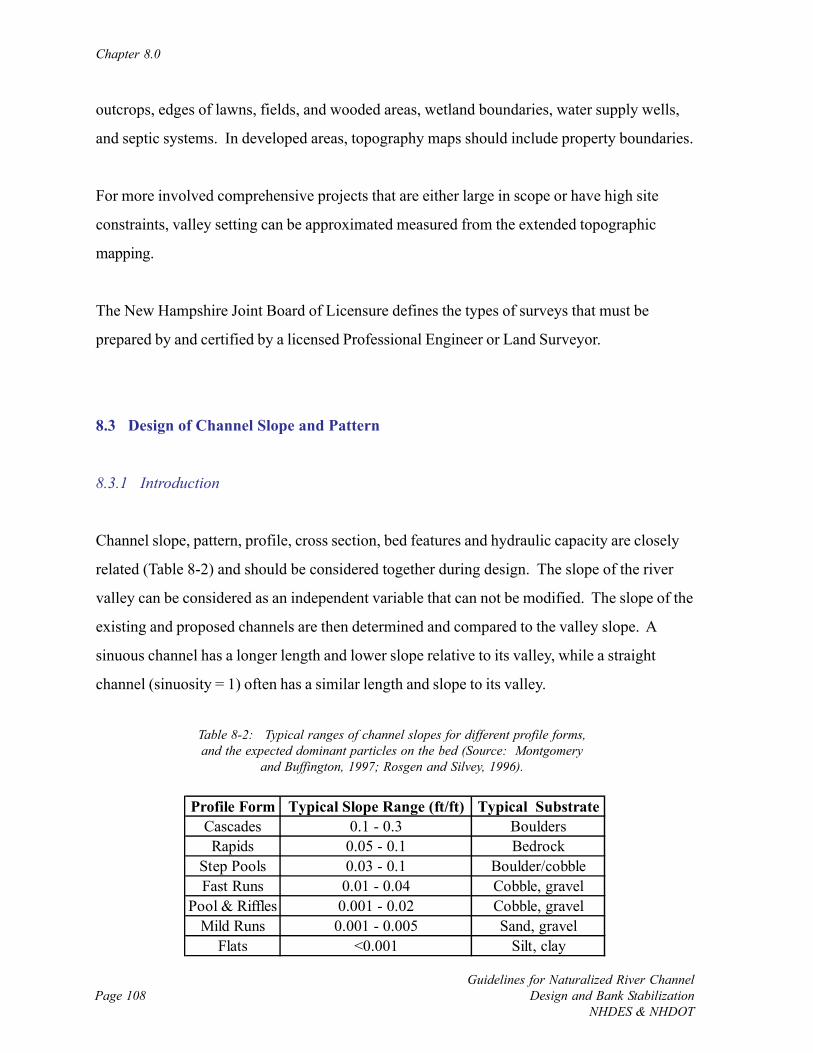
Chapter 8.0
Guidelines for Naturalized River ChannelDesign and Bank Stabilization
NHDES & NHDOTPage 108
Profile Form Typical Slope Range (ft/ft) Typical SubstrateCascades 0.1 - 0.3 BouldersRapids 0.05 - 0.1 Bedrock
Step Pools 0.03 - 0.1 Boulder/cobbleFast Runs 0.01 - 0.04 Cobble, gravel
Pool & Riffles 0.001 - 0.02 Cobble, gravelMild Runs 0.001 - 0.005 Sand, gravel
Flats <0.001 Silt, clay
Table 8-2: Typical ranges of channel slopes for different profile forms,and the expected dominant particles on the bed (Source: Montgomery
and Buffington, 1997; Rosgen and Silvey, 1996).
outcrops, edges of lawns, fields, and wooded areas, wetland boundaries, water supply wells,
and septic systems. In developed areas, topography maps should include property boundaries.
For more involved comprehensive projects that are either large in scope or have high site
constraints, valley setting can be approximated measured from the extended topographic
mapping.
The New Hampshire Joint Board of Licensure defines the types of surveys that must be
prepared by and certified by a licensed Professional Engineer or Land Surveyor.
8.3 Design of Channel Slope and Pattern
8.3.1 Introduction
Channel slope, pattern, profile, cross section, bed features and hydraulic capacity are closely
related (Table 8-2) and should be considered together during design. The slope of the river
valley can be considered as an independent variable that can not be modified. The slope of the
existing and proposed channels are then determined and compared to the valley slope. A
sinuous channel has a longer length and lower slope relative to its valley, while a straight
channel (sinuosity = 1) often has a similar length and slope to its valley.
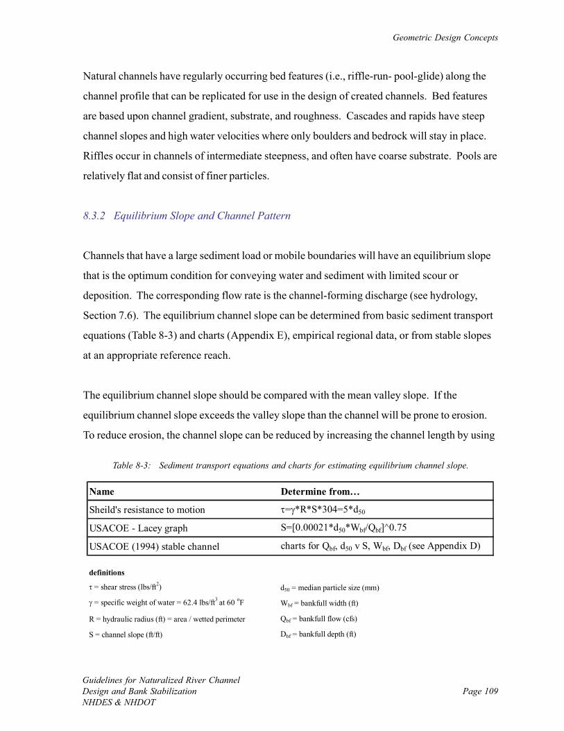
Geometric Design Concepts
Guidelines for Naturalized River ChannelDesign and Bank StabilizationNHDES & NHDOT
Page 109
Name Determine from…
Sheild's resistance to motion τ=γ*R*S*304=5*d50
USACOE - Lacey graph S=[0.00021*d50*Wbf/Qbf]^0.75
USACOE (1994) stable channel charts for Qbf, d50 v S, Wbf, Dbf (see Appendix D)
definitions
τ = shear stress (lbs/ft2) d50 = median particle size (mm)
γ = specific weight of water = 62.4 lbs/ft3 at 60 oF Wbf = bankfull width (ft)
R = hydraulic radius (ft) = area / wetted perimeter Qbf = bankfull flow (cfs)
S = channel slope (ft/ft) Dbf = bankfull depth (ft)
Table 8-3: Sediment transport equations and charts for estimating equilibrium channel slope.
Natural channels have regularly occurring bed features (i.e., riffle-run- pool-glide) along the
channel profile that can be replicated for use in the design of created channels. Bed features
are based upon channel gradient, substrate, and roughness. Cascades and rapids have steep
channel slopes and high water velocities where only boulders and bedrock will stay in place.
Riffles occur in channels of intermediate steepness, and often have coarse substrate. Pools are
relatively flat and consist of finer particles.
8.3.2 Equilibrium Slope and Channel Pattern
Channels that have a large sediment load or mobile boundaries will have an equilibrium slope
that is the optimum condition for conveying water and sediment with limited scour or
deposition. The corresponding flow rate is the channel-forming discharge (see hydrology,
Section 7.6). The equilibrium channel slope can be determined from basic sediment transport
equations (Table 8-3) and charts (Appendix E), empirical regional data, or from stable slopes
at an appropriate reference reach.
The equilibrium channel slope should be compared with the mean valley slope. If the
equilibrium channel slope exceeds the valley slope than the channel will be prone to erosion.
To reduce erosion, the channel slope can be reduced by increasing the channel length by using
Chapter 8.0
Guidelines for Naturalized River ChannelDesign and Bank Stabilization
NHDES & NHDOTPage 110
a sinuous alignment. Irregular sinuous or regular repeating meandering patterns will increase
channel length and decrease slope.
If the equilibrium channel slope is less than the valley slope than the channel will be prone to
deposition. To reduce deposition, sediment transport can be increased by increasing the
channel slope, and thus water velocity, by straightening the channel. This management
activity is typically not recommended as it can increase downstream flooding, severely impair
local aquatic habitat, and work against natural channel evolution.
In some cases it may not be possible to create the desired pattern when excess slope is
present. In these cases, the mean channel slope may be reduced by providing one or more
riffles or vortex weirs to lower the bed at a fixed point that is protected from scour.
In summary, one should identify the equilibrium slope, identify the likely pattern for the given
slope found in a natural channel of the given type, and then set the length, grade changes, and
thalweg location to provide the appropriate slope and pattern.
8.3.2.1 Non-Alluvial, Rigid Boundary Channel
The design of non-alluvial, rigid boundary channels is common practice for local drainage,
flood control, and transportation-related projects. Channel alignment is often constrained by
topography, developed land, or infrastructure including highways, utilities, or even property
boundaries. Channel alignment has to consider its end junctions with existing channels up and
downstream. The overall length is then measured and the available slope determined. Rigid
boundary channels often use compact trapezoidal cross sections that convey water in an
efficient manner but consequently sacrifice environmental quality and habitat. They usually
have relatively steep banks at angles ranging from one to four parts horizontal to one part
vertical, and commonly have artificial linings or smooth earth perimeters. It is recommended
that artificial linings be avoided and that the natural river bed be maintained in all designs,
including those in an urban landscape.
Geometric Design Concepts
Guidelines for Naturalized River ChannelDesign and Bank StabilizationNHDES & NHDOT
Page 111
The natural analog to the constructed non-alluvial and rigid boundary channel is the natural
sediment source channel in steep terrain. The two channel types behave in a similar manner,
although the constructed channel is often located on more gently sloping terrain in a
developed landscape. Non-alluvial and rigid boundary channels often have high sediment
transport rates, and their banks and beds are relatively insensitive to scour. As a result, they
are less vulnerable to excessive sediment deposition and are not very dependent on an
equilibrium slope. Their preferred slope allows them to be slightly prone to scour to
discourage deposition, and accept that their erosion-resistant banks prevent excessive scour.
Their pattern can be independent of slope.
8.3.2.2 Alluvial Channels
Naturalized created alluvial channels should have a pattern compatible to the bed slope and
discharge rates if long-term stability is desired with minimal erosion and deposition.
Determine the equilibrium slope, profile bed features, and then the appropriate pattern that a
natural river would have. In general, the overall vertical change in alluvial bed elevation of
the proposed channel is controlled by existing geologic and topographic conditions and cannot
be changed. However, the length of channel and its alignment may be adjusted by altering the
sinuosity to establish the desired channel bed slope. Knowing the bankfull discharge, the
range of stable slope estimates for each pattern can also be estimated from sediment transport
equations or reference reaches.
8.3.3 Channel Pattern
The desirable channel patterns are typically sinuous or straight in order to avoid the instability
and large width of braided channels (Figure 8-2). However, sometimes slope and bankfull
discharge dictate a braided channel pattern. The meandering pattern has advantages in that it
is conducive to a wide range of habitats. The straight channel requires little land and is easy
to construct. The disadvantage of meandering channels is that lateral and downstream
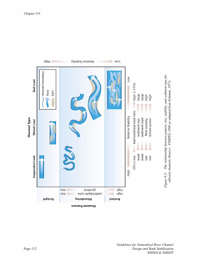
Chapter 8.0
Guidelines for Naturalized River ChannelDesign and Bank Stabilization
NHDES & NHDOTPage 112
Figu
re 8
-2:
The
rela
tions
hip
betw
een
patte
rn, s
ize,
sta
bilit
y, an
d se
dim
ent t
ype
for
allu
vial
cha
nnel
s (S
ourc
e: F
ISRW
G, 1
998
as a
dapt
ed fr
om S
chum
m, 1
977)
.
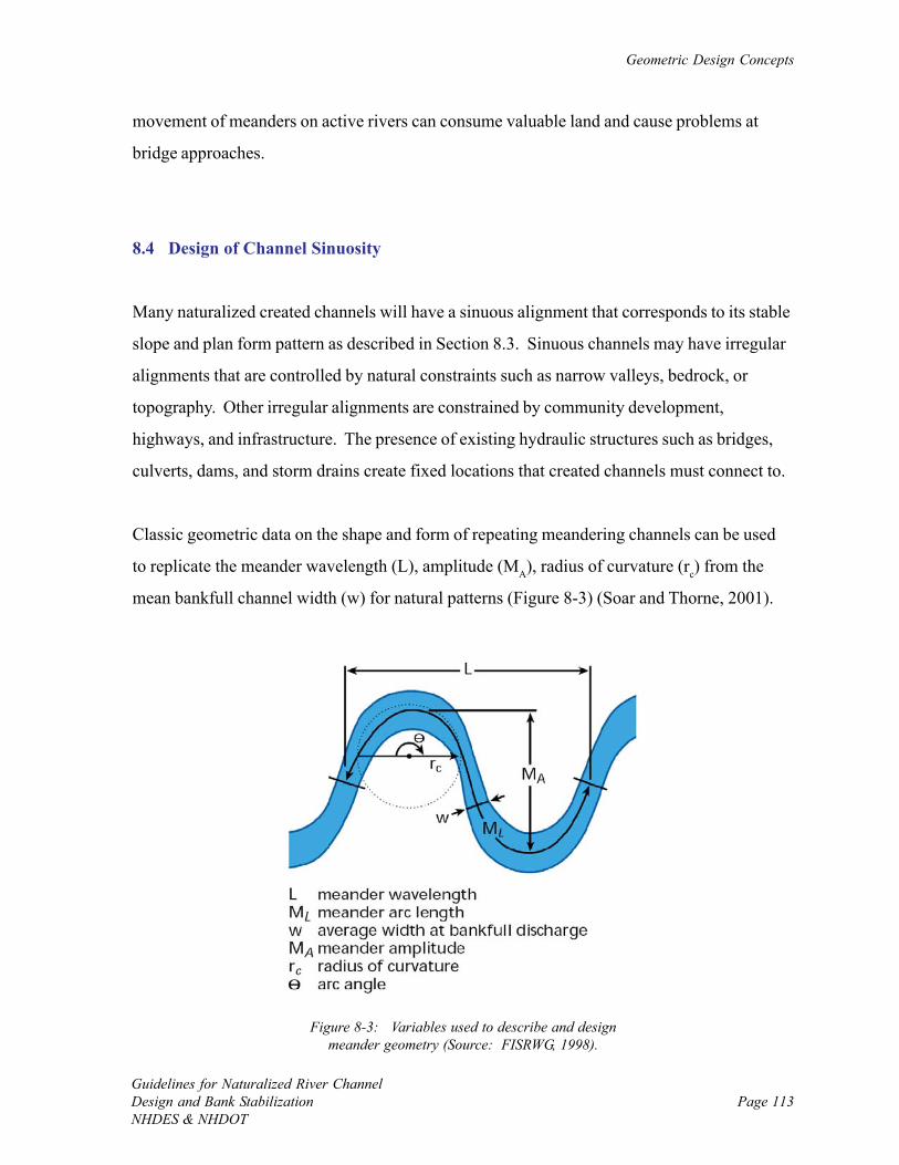
Geometric Design Concepts
Guidelines for Naturalized River ChannelDesign and Bank StabilizationNHDES & NHDOT
Page 113
Figure 8-3: Variables used to describe and designmeander geometry (Source: FISRWG, 1998).
movement of meanders on active rivers can consume valuable land and cause problems at
bridge approaches.
8.4 Design of Channel Sinuosity
Many naturalized created channels will have a sinuous alignment that corresponds to its stable
slope and plan form pattern as described in Section 8.3. Sinuous channels may have irregular
alignments that are controlled by natural constraints such as narrow valleys, bedrock, or
topography. Other irregular alignments are constrained by community development,
highways, and infrastructure. The presence of existing hydraulic structures such as bridges,
culverts, dams, and storm drains create fixed locations that created channels must connect to.
Classic geometric data on the shape and form of repeating meandering channels can be used
to replicate the meander wavelength (L), amplitude (MA), radius of curvature (rc) from the
mean bankfull channel width (w) for natural patterns (Figure 8-3) (Soar and Thorne, 2001).
Chapter 8.0
Guidelines for Naturalized River ChannelDesign and Bank Stabilization
NHDES & NHDOTPage 114
L = 10.9(w)1.01
MA = 2.7(w)1.1
L = 4.7(R)0.98
The meander bend radius typically varies from 2.3 to 25 times the bankfull channel width.
Local river characteristics obtained from reference reaches must also be considered.
Guidance on determining mender geometry can be found in the Vermont Geomorphic
Assessment Protocols (see Appendix H in VTANR, 2004). Williams (1986) provides
information on the meander geometry and many rivers in North America.
8.5 Design of Channel Cross Section
The mean channel depth, width, and side slope conditions are established after determining the
design discharges and slope for the desired pattern. Engineers can readily determine the
required typical cross section geometry based on rigid boundary hydraulics for a given
discharge and slope, and then include features to mimic the naturally stable reference reach
such as a low flow channel and small low flood plain, or flood bench. The short- and long-
term channel roughness must be estimated based on anticipated bank vegetation, substrate,
and bed features. The tendency has been to use relatively compact cross sections that
minimize the perimeter length, excavation, costs, and land. Details on cross section design for
rigid boundary channels are contained in Section 9.4.2.
Keep in mind that the design of stable cross sections is not a precise practice due to the highly
variable river environment. Flow that exerts force on the river bed and banks, and its ability
to change rapidly, complicates construction of specific cross section dimensions. The main
objective of cross section design is to approximate stable dimensions so that once constructed
the channel will recover towards and achieve a stable equilibrium more rapidly than if the
project is not installed. Designing the shape of the cross section at each location to match the
channel plan and profile (Figure 8-4) will likely speed the return to equilibrium.
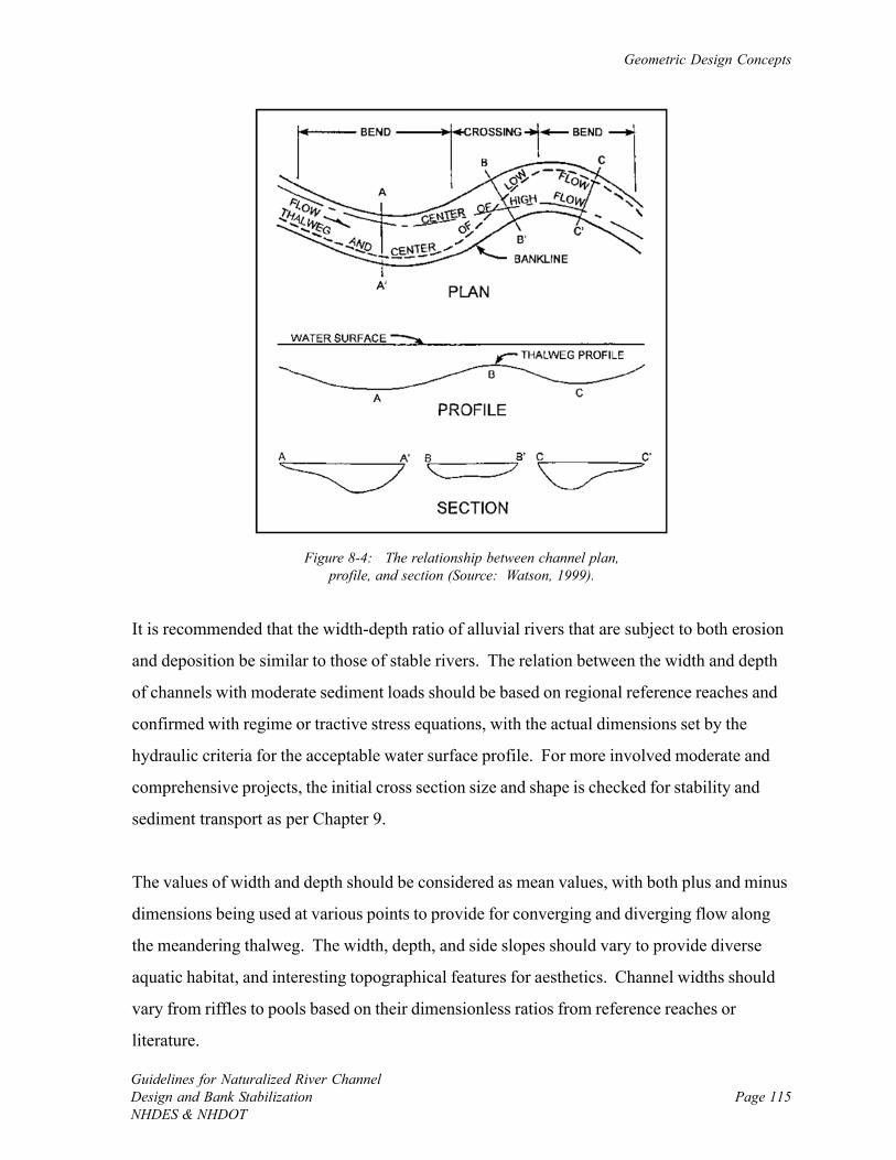
Geometric Design Concepts
Guidelines for Naturalized River ChannelDesign and Bank StabilizationNHDES & NHDOT
Page 115
Figure 8-4: The relationship between channel plan,profile, and section (Source: Watson, 1999).
It is recommended that the width-depth ratio of alluvial rivers that are subject to both erosion
and deposition be similar to those of stable rivers. The relation between the width and depth
of channels with moderate sediment loads should be based on regional reference reaches and
confirmed with regime or tractive stress equations, with the actual dimensions set by the
hydraulic criteria for the acceptable water surface profile. For more involved moderate and
comprehensive projects, the initial cross section size and shape is checked for stability and
sediment transport as per Chapter 9.
The values of width and depth should be considered as mean values, with both plus and minus
dimensions being used at various points to provide for converging and diverging flow along
the meandering thalweg. The width, depth, and side slopes should vary to provide diverse
aquatic habitat, and interesting topographical features for aesthetics. Channel widths should
vary from riffles to pools based on their dimensionless ratios from reference reaches or
literature.
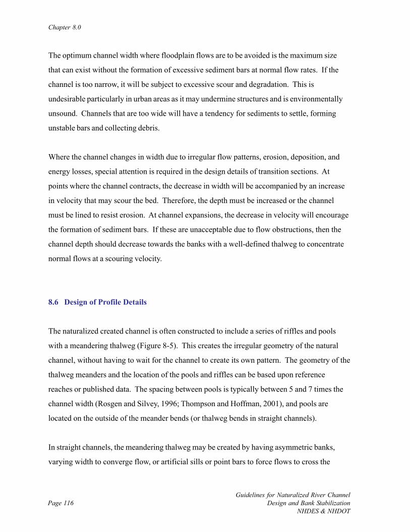
Chapter 8.0
Guidelines for Naturalized River ChannelDesign and Bank Stabilization
NHDES & NHDOTPage 116
The optimum channel width where floodplain flows are to be avoided is the maximum size
that can exist without the formation of excessive sediment bars at normal flow rates. If the
channel is too narrow, it will be subject to excessive scour and degradation. This is
undesirable particularly in urban areas as it may undermine structures and is environmentally
unsound. Channels that are too wide will have a tendency for sediments to settle, forming
unstable bars and collecting debris.
Where the channel changes in width due to irregular flow patterns, erosion, deposition, and
energy losses, special attention is required in the design details of transition sections. At
points where the channel contracts, the decrease in width will be accompanied by an increase
in velocity that may scour the bed. Therefore, the depth must be increased or the channel
must be lined to resist erosion. At channel expansions, the decrease in velocity will encourage
the formation of sediment bars. If these are unacceptable due to flow obstructions, then the
channel depth should decrease towards the banks with a well-defined thalweg to concentrate
normal flows at a scouring velocity.
8.6 Design of Profile Details
The naturalized created channel is often constructed to include a series of riffles and pools
with a meandering thalweg (Figure 8-5). This creates the irregular geometry of the natural
channel, without having to wait for the channel to create its own pattern. The geometry of the
thalweg meanders and the location of the pools and riffles can be based upon reference
reaches or published data. The spacing between pools is typically between 5 and 7 times the
channel width (Rosgen and Silvey, 1996; Thompson and Hoffman, 2001), and pools are
located on the outside of the meander bends (or thalweg bends in straight channels).
In straight channels, the meandering thalweg may be created by having asymmetric banks,
varying width to converge flow, or artificial sills or point bars to force flows to cross the
Geometric Design Concepts
Guidelines for Naturalized River ChannelDesign and Bank StabilizationNHDES & NHDOT
Page 117
(A) (B)
Figure 8-5: Distribution of riffles and pools along a meandering thalweg in ameandering (A) and straight (B) channel (Source: Watson, 1999).
center of the channel. Clean gravels and cobbles may be used to control the bed elevations in
areas designated to be riffles.
8.6.1 Control of Aggradation
The aggrading channel fills with sediments due to a sediment load greater than the sediment
transport capacity. Aggradation of existing channels can be controlled where necessary by
reducing the sediment load or by increasing the sediment transport capacity. The sediment
load may be reduced by use of sediment traps or reservoirs, bank stabilization, debris basins,
and land use policies in developed areas to discourage erosion. The measures can often be
readily applied on small watersheds, but are difficult to implement on large watersheds.
The sediment transport capacity can be increased by reducing the cross section flow area
either by making the river narrower or shallower that results in higher velocities that will carry
more sediment. This may be accomplished by changing channel geometry alone or by using
Chapter 8.0
Guidelines for Naturalized River ChannelDesign and Bank Stabilization
NHDES & NHDOTPage 118
training structures such as deflectors, vanes, or groins. Other ways to increase sediment
transport include increasing slope and reducing hydraulic friction to increase mean velocity.
For some channels where sediment capture and storage is the dominant natural phenomena
such as braided channels, enough room is needed across the valley to accommodate a channel
that is likely to widen. Sometimes this may necessitate relocating or removing infrastructure
such as roads or buildings.
8.6.2 Control of Degradation
The degradation of channels occurs when the rate of sediment transport exceeds sediment
supply. The degradation may be controlled by decreasing the sediment transport of the river,
increasing supply, creating vertical barriers, or lining the channel.
The transport rate can be reduced by decreasing the slope to reduce velocities. The slope of
small rivers is often reduced by using a series of weirs to establish a fixed bed profile at an
equilibrium slope, or by using a longer sinuous alignment. Larger rivers have their peak
velocities reduced by impounding reservoirs that store large quantities of water for gradual
release over a period of time. Widening the channel can increase friction and in that way
decrease the scouring velocities, but is only practical where sufficient land is available.
Increasing the sediment load is rarely done to control degradation because of the concern forincreased sediment loads to downstream areas and impairment to aquatic habitat.
Creating vertical barriers, also known as grade control, is a popular way to control channel
degradation. The ability to control the channel bed is largely a function of channel size, the
existing and predicted level of down cutting in the channel (i.e., how incised the channel is and
will attempt to become), how unstable the bed is at the time of installation, and how energized
the channel becomes during flood events and the degree of channel adjustment that typically
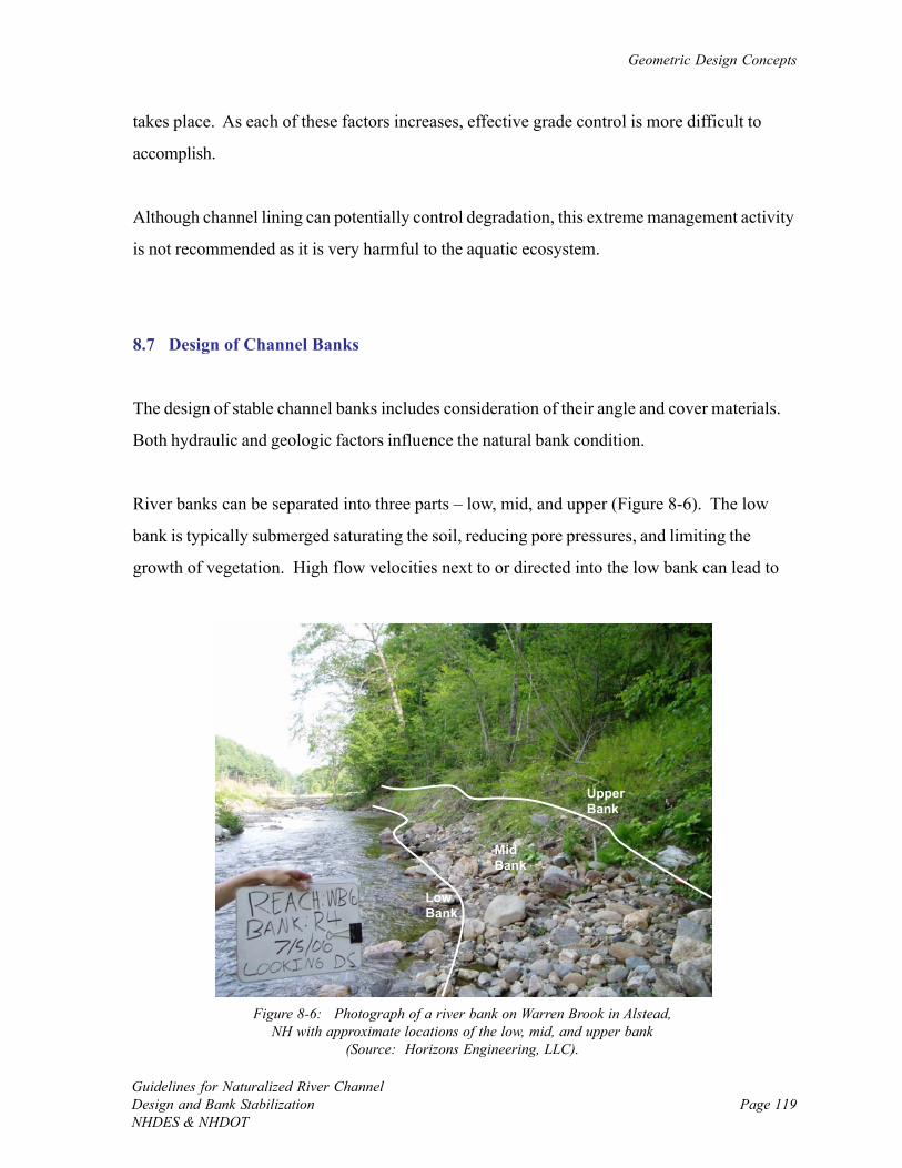
Geometric Design Concepts
Guidelines for Naturalized River ChannelDesign and Bank StabilizationNHDES & NHDOT
Page 119
Low Bank
Mid Bank
Upper Bank
Figure 8-6: Photograph of a river bank on Warren Brook in Alstead,NH with approximate locations of the low, mid, and upper bank
(Source: Horizons Engineering, LLC).
takes place. As each of these factors increases, effective grade control is more difficult to
accomplish.
Although channel lining can potentially control degradation, this extreme management activity
is not recommended as it is very harmful to the aquatic ecosystem.
8.7 Design of Channel Banks
The design of stable channel banks includes consideration of their angle and cover materials.
Both hydraulic and geologic factors influence the natural bank condition.
River banks can be separated into three parts – low, mid, and upper (Figure 8-6). The low
bank is typically submerged saturating the soil, reducing pore pressures, and limiting the
growth of vegetation. High flow velocities next to or directed into the low bank can lead to
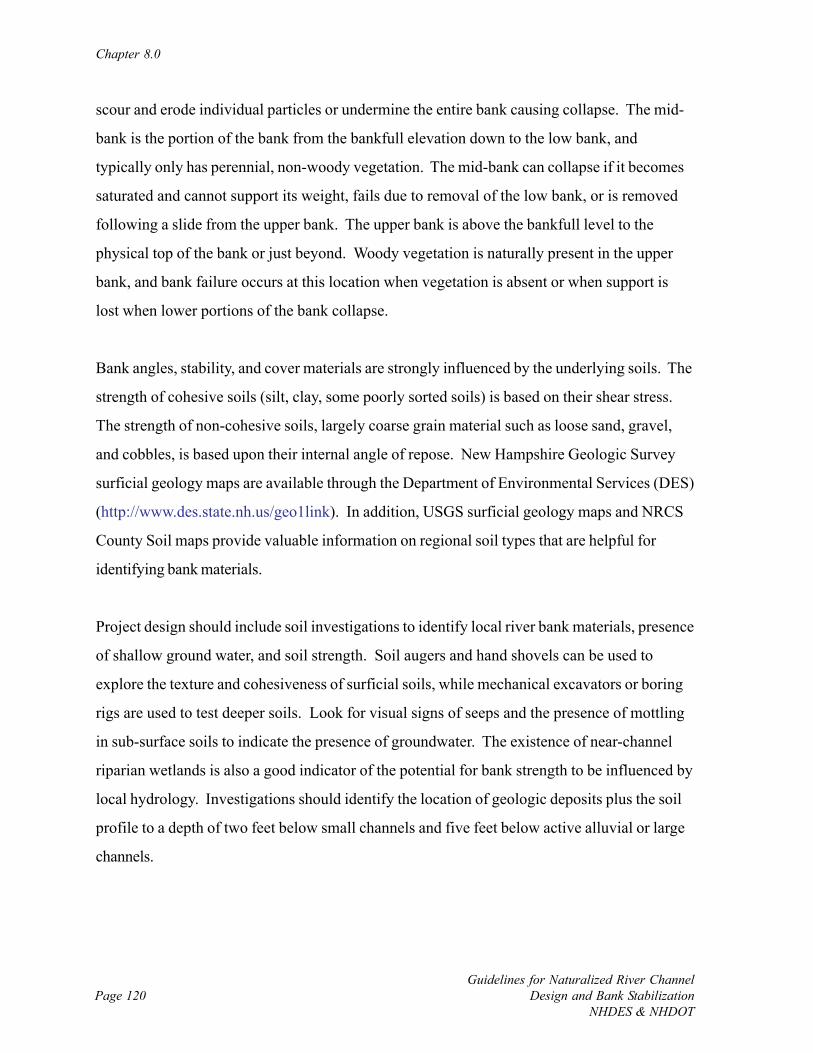
Chapter 8.0
Guidelines for Naturalized River ChannelDesign and Bank Stabilization
NHDES & NHDOTPage 120
scour and erode individual particles or undermine the entire bank causing collapse. The mid-
bank is the portion of the bank from the bankfull elevation down to the low bank, and
typically only has perennial, non-woody vegetation. The mid-bank can collapse if it becomes
saturated and cannot support its weight, fails due to removal of the low bank, or is removed
following a slide from the upper bank. The upper bank is above the bankfull level to the
physical top of the bank or just beyond. Woody vegetation is naturally present in the upper
bank, and bank failure occurs at this location when vegetation is absent or when support is
lost when lower portions of the bank collapse.
Bank angles, stability, and cover materials are strongly influenced by the underlying soils. The
strength of cohesive soils (silt, clay, some poorly sorted soils) is based on their shear stress.
The strength of non-cohesive soils, largely coarse grain material such as loose sand, gravel,
and cobbles, is based upon their internal angle of repose. New Hampshire Geologic Survey
surficial geology maps are available through the Department of Environmental Services (DES)
(http://www.des.state.nh.us/geo1link). In addition, USGS surficial geology maps and NRCS
County Soil maps provide valuable information on regional soil types that are helpful for
identifying bank materials.
Project design should include soil investigations to identify local river bank materials, presence
of shallow ground water, and soil strength. Soil augers and hand shovels can be used to
explore the texture and cohesiveness of surficial soils, while mechanical excavators or boring
rigs are used to test deeper soils. Look for visual signs of seeps and the presence of mottling
in sub-surface soils to indicate the presence of groundwater. The existence of near-channel
riparian wetlands is also a good indicator of the potential for bank strength to be influenced by
local hydrology. Investigations should identify the location of geologic deposits plus the soil
profile to a depth of two feet below small channels and five feet below active alluvial or large
channels.
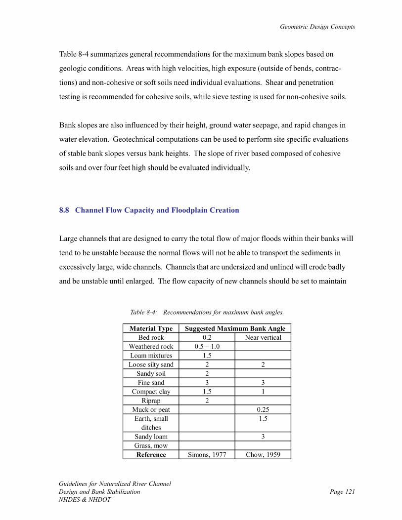
Geometric Design Concepts
Guidelines for Naturalized River ChannelDesign and Bank StabilizationNHDES & NHDOT
Page 121
Material TypeBed rock 0.2 Near vertical
Weathered rock 0.5 – 1.0Loam mixtures 1.5Loose silty sand 2 2
Sandy soil 2Fine sand 3 3
Compact clay 1.5 1Riprap 2
Muck or peat 0.25Earth, small
ditches1.5
Sandy loam 3Grass, mowReference Simons, 1977 Chow, 1959
Suggested Maximum Bank Angle
Table 8-4: Recommendations for maximum bank angles.
Table 8-4 summarizes general recommendations for the maximum bank slopes based on
geologic conditions. Areas with high velocities, high exposure (outside of bends, contrac-
tions) and non-cohesive or soft soils need individual evaluations. Shear and penetration
testing is recommended for cohesive soils, while sieve testing is used for non-cohesive soils.
Bank slopes are also influenced by their height, ground water seepage, and rapid changes in
water elevation. Geotechnical computations can be used to perform site specific evaluations
of stable bank slopes versus bank heights. The slope of river based composed of cohesive
soils and over four feet high should be evaluated individually.
8.8 Channel Flow Capacity and Floodplain Creation
Large channels that are designed to carry the total flow of major floods within their banks will
tend to be unstable because the normal flows will not be able to transport the sediments in
excessively large, wide channels. Channels that are undersized and unlined will erode badly
and be unstable until enlarged. The flow capacity of new channels should be set to maintain
Chapter 8.0
Guidelines for Naturalized River ChannelDesign and Bank Stabilization
NHDES & NHDOTPage 122
stable equilibrium, unless special conditions warrant the frequent sediment removal to prevent
erosion.
Flows in excess of the bankfull discharge are normally conveyed by floodplains. If the
floodplain is not available or accessible for conveying flow, perhaps due to development in the
river corridor and channelization, design should consider returning floodplain usage or at least
mimicking the channel-overbank dual conveyance system with a smaller floodplain (see Figure
7-2). These features that convey overbank flow outside of the main channel yet within the
active river channel are often referred to as flood benches, and are a common element in
naturalized channel design. In situations where natural floodplains are disconnected due to
channel incision or have been developed and filled in, a low or high terrace floodplain can be
excavated to carry overbank flows. Floodplain dimensions are sized based on a reference
reach or the desired flow velocity and particle transport, and the main challenge is to find
areas near the river channel where there is ample room to re-establish floodplain.
Floodplain creation is a form of naturalized flood control projects where the cross section of
the main channel is sized to convey normal flows and floods with average return frequencies
of up to about two years. The normal flow channel is thus relatively narrowed compared to
traditional flood channels, and can have sufficient concentrated flow to maintain adequate
water depth for aquatic life and sediment transport (Figure 8-7). This helps improve both the
environmental quality, physical stability, and the appearance of the channel.
After setting the size of the main channel to carry normal flows, the floodplain is sized to
convey flood flows. The surface of the floodplain is above the typical flow elevation of the
main channel and therefore the floodplain surface is often dry. The large size, relative to the
main channel, and dry surface of the floodplain allow for the planting of ground covers,
shrubs, and trees. In addition to its important roles for the rivers, the floodplain serves as
open space, can be used for recreation, and is a green belt corridor serving as a buffer between
the main channel and adjacent land uses. The floodplain may be on either or both sides of the
main channel, and can be designed to vary in width to mimic a natural system, fit into a
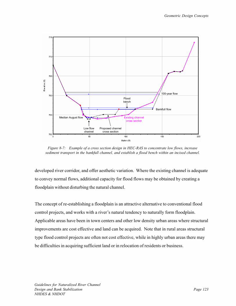
Geometric Design Concepts
Guidelines for Naturalized River ChannelDesign and Bank StabilizationNHDES & NHDOT
Page 123
100-year flow
Bankfull flow
Median August flow
Proposed channel cross section
Existing channel cross section
Low flow channel
Flood bench
Figure 8-7: Example of a cross section design in HEC-RAS to concentrate low flows, increasesediment transport in the bankfull channel, and establish a flood bench within an incised channel.
developed river corridor, and offer aesthetic variation. Where the existing channel is adequate
to convey normal flows, additional capacity for flood flows may be obtained by creating a
floodplain without disturbing the natural channel.
The concept of re-establishing a floodplain is an attractive alternative to conventional flood
control projects, and works with a river’s natural tendency to naturally form floodplain.
Applicable areas have been in town centers and other low density urban areas where structural
improvements are cost effective and land can be acquired. Note that in rural areas structural
type flood control projects are often not cost effective, while in highly urban areas there may
be difficulties in acquiring sufficient land or in relocation of residents or business.
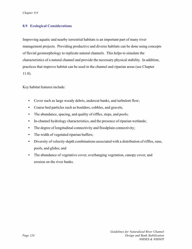
Chapter 8.0
Guidelines for Naturalized River ChannelDesign and Bank Stabilization
NHDES & NHDOTPage 124
8.9 Ecological Considerations
Improving aquatic and nearby terrestrial habitats is an important part of many river
management projects. Providing productive and diverse habitats can be done using concepts
of fluvial geomorphology to replicate natural channels. This helps to simulate the
characteristics of a natural channel and provide the necessary physical stability. In addition,
practices that improve habitat can be used in the channel and riparian areas (see Chapter
11.0).
Key habitat features include:
• Cover such as large woody debris, undercut banks, and turbulent flow;
• Coarse bed particles such as boulders, cobbles, and gravels;
• The abundance, spacing, and quality of riffles, steps, and pools;
• In-channel hydrology characteristics, and the presence of riparian wetlands;
• The degree of longitudinal connectivity and floodplain connectivity;
• The width of vegetated riparian buffers;
• Diversity of velocity-depth combinations associated with a distribution of riffles, runs,
pools, and glides; and
• The abundance of vegetative cover, overhanging vegetation, canopy cover, and
erosion on the river banks.
Page 125Guidelines for Naturalized River ChannelDesign and Bank StabilizationNHDES & NHDOT
CHAPTER 9.0: COMPUTATIONAL DESIGN TOOLS
9.1 Introduction
Methods used for naturalized river channel design and bank stabilization projects can be
grouped into one of three types of general approaches: empirical, analog, and analytical.
• Empirical – Stable channel dimensions at the project site are predicted using
regression relationships established from extensive data sets of channel geometry and
flow characteristics measured at relatively healthy rivers.
• Analog – Stable channel dimensions and a single dominant design discharge at the
project site are determined from observation of the geomorphic characteristics of a
nearby healthy reference reach with similar slope and substrate.
• Analytical – Project site characteristics such as discharge, stable channel dimensions,
or sediment transport rates are approximated via physical-based equations or models.
Typical outputs of these approaches include stable channel dimensions, elevations to place
instream and bank structures, and anticipated sediment erosion and deposition (continuity).
Each of the three design approaches has advantages and limitations, and alone none is
universally applicable. Effective designs use components of empirical, analog, and analytical
methods to allow for comparison of findings and generating a design solution that is validated
by multiple approaches. The increased initial investment in design expands the likelihood that
installed projects will meet project goals, and not be prone to common failures such as
dislocation during large flood events or reduced habitat quality during low flows. This
comprehensive design approach is ultimately more economical as project failures require
costly repairs and maintenance.
The computational tools used in river channel design and bank stabilization projects is mainly
determined by whether a project is routine, moderate, or comprehensive (Figure 9-1).
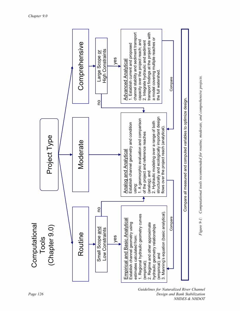
Chapter 9.0
Guidelines for Naturalized River ChannelDesign and Bank Stabilization
NHDES & NHDOTPage 126
Pro
ject
Typ
e
Mod
erat
eR
outin
eC
ompr
ehen
sive
yes
Sm
all S
cope
and
Low
Con
stra
ints
Larg
e Sc
ope
orH
igh
Con
stra
ints
no
yes
no
Com
puta
tiona
lTo
ols
(Cha
pter
9.0
)
Com
pare
all
mea
sure
d an
d co
mpu
ted
varia
bles
to o
ptim
ize
desi
gn.
Em
piric
al a
nd B
asic
Ana
lytic
alE
stab
lish
chan
nel g
eom
etry
usi
ng
estim
ates
cal
cula
ted
from
:1.
Reg
iona
l hyd
raul
ic g
eom
etry
cur
ves
(em
piric
al);
2. R
egim
e an
d ot
her a
ppro
xim
ate
hydr
aulic
geo
met
ry re
latio
nshi
ps
(em
piric
al);
and
3. M
anni
ng’s
equ
atio
n (b
asic
ana
lytic
al).
Adva
nced
Ana
lytic
al1.
Est
ablis
h cu
rrent
and
pro
pose
d ch
anne
l sta
bilit
y an
d se
dim
ent t
rans
port
capa
city
ove
r the
pro
ject
reac
h; a
nd2.
Inte
grat
e hy
drau
lic a
nd s
edim
ent
trans
port
findi
ngs
at th
e pr
ojec
t site
with
a
mod
el c
over
ing
mul
tiple
reac
hes
or
the
full
wat
ersh
ed.
Com
pare
Com
pare
Anal
og a
nd A
naly
tical
Esta
blis
h ch
anne
l geo
met
ry a
nd c
ondi
tion
usin
g:1.
A g
eom
orph
ic e
valu
atio
n an
d co
mpa
rison
of
the
proj
ect a
nd re
fere
nce
reac
hes
(ana
log)
; and
2. H
ydra
ulic
mod
elin
g ov
er a
rang
e of
bot
h st
ruct
ural
ly a
nd e
colo
gica
lly im
porta
nt d
esig
n flo
ws
over
the
proj
ect r
each
(ana
lytic
al).
Figu
re 9
-1:
Com
puta
tiona
l too
ls re
com
men
ded
for
rout
ine,
mod
erat
e, a
nd c
ompr
ehen
sive
pro
ject
s.
Computational Design Tools
Guidelines for Naturalized River ChannelDesign and Bank StabilizationNHDES & NHDOT
Page 127
Routine projects that are both small in scope and have low site constraints typically are
designed by a combination of existing empirical relationships (regional curves or generalized
Regime theory) and basic analytical techniques such as the Manning’s and continuity
equations. The approximation of stable channel dimensions and water surface elevations
associated with a design discharge using these rapid methods is appropriate for the low level
of risk and minimal funding associated with routine projects. Such approaches can also be
useful for temporary, emergency repairs where rapid response is needed. Routine projects
that are larger in scope or have more risk and projects that are classified as moderate require
more detailed analysis and thus more computational tools are recommended for design.
Analog and analytical methods such as hydraulic modeling are used to establish stable channel
dimensions, often with reference to a locally stable site. In addition, hydraulic modeling offers
insight into how the site operates before and after implementation over a range of flows. This
level of analysis is also applicable for comprehensive projects that are not large in scope or
have high constraints. For large or high risk projects, channel stability calculations and
sediment transport modeling are added to the recommended computational approaches to
increase the chances of meeting projects goals and objectives over a larger site with
challenging physical constraints. In this situation, hydraulics and sediment transport analysis
should be integrated and scaled up to the river system or watershed level to understand the
influence of the proposed project.
The selection of computational tools for river channel design and bank stabilization is also
influenced by project goals. For example, if the main project goal of a moderate project is to
limit the delivery of eroded sediments to downstream locations, sediment transport
calculations are added to the list of recommended computational tools.
The broad geomorphic characterization of a channel reach as alluvial or non-alluvial also
guides selection of computational tools (Figure 9-2). Analog and empirical approaches have
been established for alluvial channels, or those that are self-formed by deposited sediments
under the present hydrology, and thus their application is most appropriate on this river type.
Analytical approaches are most suited for non-alluvial channels, which are typically straighter,
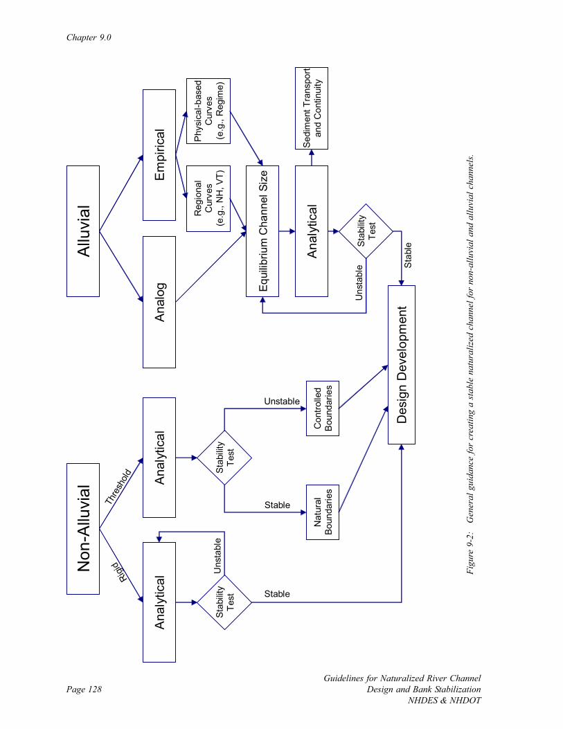
Chapter 9.0
Guidelines for Naturalized River ChannelDesign and Bank Stabilization
NHDES & NHDOTPage 128
Allu
vial
Non
-Allu
vial
Ana
lytic
alA
naly
tical
Sta
bilit
yTe
st
Con
trolle
dB
ound
arie
sN
atur
alBo
unda
ries
Des
ign
Dev
elop
men
tUnstable
Stable
Ana
log
Reg
iona
lC
urve
s(e
.g.,
NH
, VT)
Phy
sica
l-bas
edC
urve
s(e
.g.,
Reg
ime)
Equi
libriu
m C
hann
el S
ize
Ana
lytic
alSe
dim
ent T
rans
port
and
Con
tinui
ty
Sta
bilit
yTe
st
Rigid
Thre
shold
Em
piric
al
Uns
tabl
e Sta
ble
Sta
bilit
yTe
st Stable
Uns
tabl
e
Figu
re 9
-2:
Gen
eral
gui
danc
e fo
r cr
eatin
g a
stab
le n
atur
aliz
ed c
hann
el fo
r no
n-al
luvi
al a
nd a
lluvi
al c
hann
els.
Computational Design Tools
Guidelines for Naturalized River ChannelDesign and Bank StabilizationNHDES & NHDOT
Page 129
steeper, and smaller than alluvial channels. Nevertheless, analog and empirical approaches are
often used today to design naturalized channels and bank stabilization projects in non-alluvial
rivers. An understanding of the limitations of application of each computational tool
discussed in this chapter is essential for accurately comparing and selecting results obtained
from different methods.
9.2 Empirical Techniques
9.2.1 Introduction
Hydraulic geometry relationships (HGRs) for designing stable river channels are a rapid
empirical design tool. Once formulated, relationships can be used to quickly estimate stable
channel dimensions, discharge and velocity, channel slope and Manning’s roughness
coefficient (N) (see review by Singh, 2003). This empirical computational tool has been
refined to the point that regional curves of the geometry of river channels are established from
many local measurements of channel dimensions.
The empirical approach to river channel design and bank stabilization projects relies on
extensive data sets to develop regression relationships to predict stable channel dimensions at
new sites. Setting channel dimensions based on regional curves is a common empirical
technique that is readily applied to a range of projects when curves exist. Many other
hydraulic geometry relationships exist that are available to double check regional estimates of
channel dimensions.
9.2.2 Regional Hydraulic Geometry Curves
The State of New Hampshire currently has provisional HGR curves (NHST, 2005) to estimate
the bankfull channel width (ft), depth (ft), and cross section area (sq ft) based on watershed
area (sq mi) (Figure 9-3). Note that the New Hampshire curves are slightly skewed towards
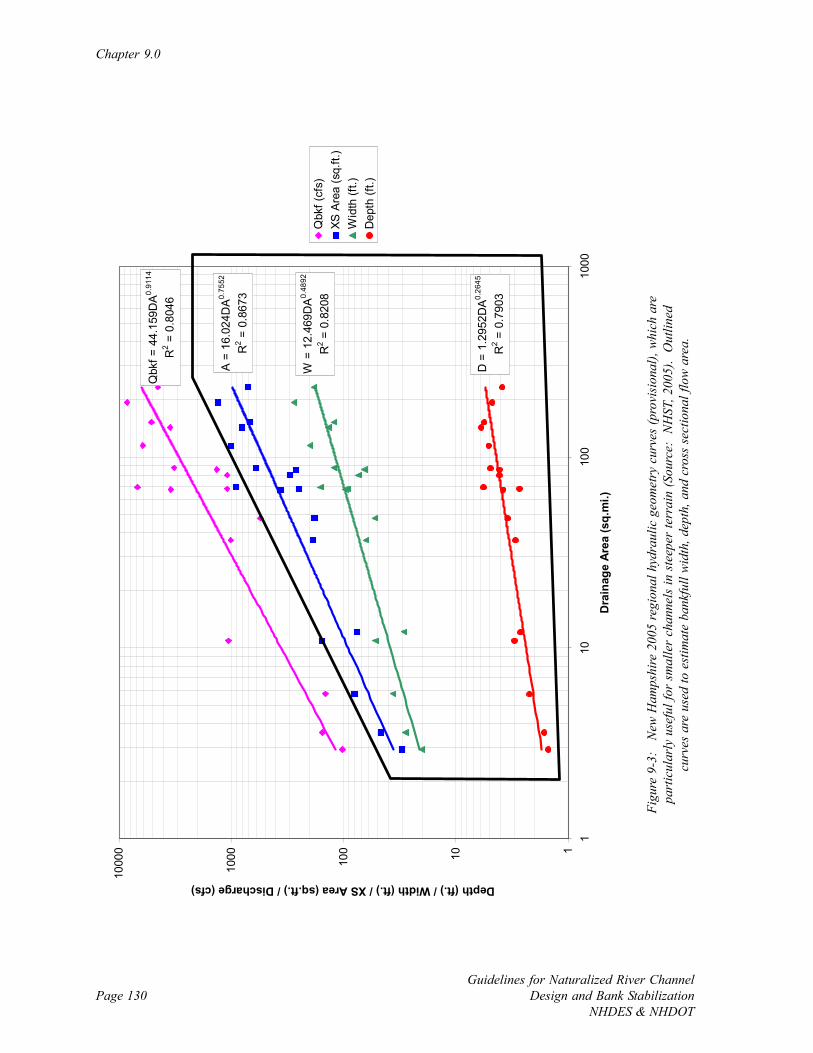
Chapter 9.0
Guidelines for Naturalized River ChannelDesign and Bank Stabilization
NHDES & NHDOTPage 130
Qbk
f = 4
4.15
9DA
0.91
14
R2 =
0.8
046
A =
16.
024D
A0.
7552
R2 =
0.8
673
W =
12.
469D
A0.
4892
R2 =
0.8
208
D =
1.2
952D
A0.
2645
R2 =
0.7
903
110100
1000
1000
0
110
100
1000
Dra
inag
e A
rea
(sq.
mi.)
Depth (ft.) / Width (ft.) / XS Area (sq.ft.) / Discharge (cfs)
Qbk
f (cf
s)XS
Are
a (s
q.ft.
)W
idth
(ft.)
Dep
th (f
t.)
Figu
re 9
-3:
New
Ham
pshi
re 2
005
regi
onal
hyd
raul
ic g
eom
etry
cur
ves
(pro
visi
onal
), w
hich
are
part
icul
arly
use
ful f
or s
mal
ler
chan
nels
in s
teep
er te
rrai
n (S
ourc
e: N
HST
, 200
5).
Out
lined
curv
es a
re u
sed
to e
stim
ate
bank
full
wid
th, d
epth
, and
cro
ss s
ectio
nal f
low
are
a.
Computational Design Tools
Guidelines for Naturalized River ChannelDesign and Bank StabilizationNHDES & NHDOT
Page 131
smaller river channels in steeper terrain as a result of including data from channels in the
White Mountains to create the curves. For larger rivers such as those in the Connecticut
River Basin, it is more appropriate to use Vermont’s HGR curves (Appendix J in VTANR,
2005) to determine bankfull width, depth, and cross sectional area. The New Hampshire
curves will be periodically updated, so check with the Rivers Management and Protection
Program in the Department of Environmental Services (DES) (http://www.des.state.nh.us/
rivers) to ensure that the most recent curves are being used.
Due to the limited time it takes to calculate stable channel dimensions using HGRs it is useful
to compare other regional estimates of channel dimensions with those from other empirical
studies. The Natural Resources Conservation Service has a growing archive of existing HGRs
and several have already been prepared for the New England Province of the Appalachian
Highlands (http://wmc.ar.nrcs.usda.gov/technical/HHSWR/Geomorphic). Other regional
curves (ME - Dudley, 2004; VT - VTANR, 2004; NY - Westergard et al., 2005) are useful to
validate estimates with the New Hampshire HGR curves.
9.2.3 Regime Equations
Regime equations (Lacey, 1930), which are the precursor to HGRs, can be used to size a
stable channel while directly considering discharge, channel slope, and substrate particle size.
Because the only dependent variable in modern HGR curves is watershed area, without
expressions for actual discharge, channel slope, or substrate, the regional curves often have
considerable data scatter. Regime equations are particularly useful if the project is in a
reference channel type that is substantially different than those used to create the HGR curves.
For example, regime equations would be useful for designing a low-gradient sand bed channel
in the seacoast region of New Hampshire as the regional HGR curves for steeper channels
would not apply. There are several sets of regime equations (e.g., Simons and Albertson,
1963; Henderson, 1966; Julien and Wargadalam, 1995; Soar and Thorne, 2001; Lee and
Julien, 2006) that can be regularly used to estimate the size of stable channels in naturalized
channel design and bank stabilization projects (Table 9-1).
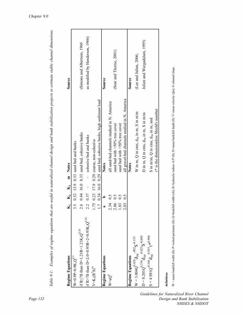
Chapter 9.0
Guidelines for Naturalized River ChannelDesign and Bank Stabilization
NHDES & NHDOTPage 132
Reg
ime
Equa
tions
K1
K2
K3
mN
otes
Sour
ceW
=0.9
P=0.
9K1Q
0.5
3.5
0.52
13.9
0.33
sand
bed
and
ban
ksif
R<7f
t tha
n D
=1.2
1R=1
.21K
2Q0.
362.
60.
4416
.00.
33sa
nd b
ed, c
ohes
ive
bank
s(S
imon
s and
Alb
erts
on, 1
960
if R>
7ft t
han
D=2
.0+0
.93R
=2+0
.93K
2Q0.
362.
20.
37-
-co
hesi
ve b
ed a
nd b
anks
as m
odifi
ed b
y H
ende
rson
, 196
6)V
=K3(
R2 S)m
1.75
0.23
17.9
0.29
coar
se, n
on-c
ohes
ive
1.7
0.34
16.0
0.29
sand
bed
, coh
esiv
e ba
nks,
high
sedi
men
t loa
dR
egim
e Eq
uatio
nsa
bN
otes
Sour
ceW
=aQ
b2.
340.
5al
l san
d-be
d ch
anne
ls st
udie
d in
N. A
mer
ica
2.86
0.5
sand
bed
with
<50
% tr
ee c
over
(Soa
r and
Tho
rne,
200
1)1.
830.
5sa
nd b
ed w
ith >
50%
tree
cov
er2.
030.
5al
l gra
vel-b
ed c
hann
els s
tudi
ed in
N. A
mer
ica
Reg
ime
Equa
tions
Not
esSo
urce
W =
3.0
04Q
0.42
6 d 50-.0
02S-0
.153
W in
m, Q
in c
ms,
d 50 i
n m
, S in
m/m
(Lee
and
Julie
n, 2
006;
D =
0.2
01Q
0.33
6 d 50-0
.025
S-0.0
60D
in m
, Q in
cm
s, d 5
0 in
m, S
in m
/mJu
lien
and
War
gada
lam
, 199
5)
S =
4.98
1Q-0
.346
d 500.
955 τ
*0.96
6S
in m
/m, Q
in c
ms,
d 50 i
n m
, and
τ* is
the
dim
ensi
onle
ss S
hiel
d's n
umbe
r
defin
ition
s
W =
mea
n ba
nkfu
ll w
idth
(ft);
P=w
ette
d pe
rimet
er (f
t); Q
=ban
kful
l wid
th (c
fs);
R=h
ydra
ulic
radi
us=A
/P (f
t); D
=mea
n ba
nkfu
ll de
pth
(ft);
V=m
ean
velo
city
(fps
); S=
chan
nel s
lope
.
Tabl
e 9-
1:
Exam
ples
of r
egim
e eq
uatio
ns th
at a
re u
sefu
l in
natu
raliz
ed c
hann
el d
esig
n an
d ba
nk s
tabi
lizat
ion
proj
ects
to e
stim
ate
stab
le c
hann
el d
imen
sion
s.
Computational Design Tools
Guidelines for Naturalized River ChannelDesign and Bank StabilizationNHDES & NHDOT
Page 133
9.2.4 Limitations and Applicability of Empirical Approaches
The rapid design tools that are established from empirical methods are useful for establishing
estimates of stable channel dimensions. Nevertheless, empirical approaches have some
limitations that may require the use of other computational tools under certain conditions.
The limitations of empirical methods include the following.
• Large regional data requirements to establish relationships
• Relationships must be used in similar systems
• Outlier observations can skew data patterns during relationship calibration
• Most appropriate for alluvial channels
• Not readily applicable to developed watersheds
• Braided channel types typically not included in relationship calibration
• Not appropriate for regulated rivers
• Variable river bed slope can influence relationships
• Limited opportunity for understanding watershed processes
• Insufficient to evaluate floodplain impacts
If empirical relationships exist for a project site yet unfavorable application conditions are
present, other approaches are needed for data validation. Stable channel dimensions
determined from physical-based analytical methods are often more appropriate when empirical
relationships may have limited use.
9.3 Analog Techniques
9.3.1 Introduction
The analog approach to river channel design and bank stabilization uses a reference reach as a
template for stable form and a single dominant design discharge, typically at bankfull flow.
Chapter 9.0
Guidelines for Naturalized River ChannelDesign and Bank Stabilization
NHDES & NHDOTPage 134
Dimensions are measured at one or more stable reference reach and replicated when con-
structing a new channel. The analog approach is closely associated with the Rosgen method
(Rosgen, 1994; Rosgen and Silvey, 1996, 1998), and many existing design manuals and
guidelines primarily follow this methodology for naturalized channel creation (e.g., TRANS,
2001; Flosi et al., 2002; KST, 2002; Doll et al., 2003). The Rosgen method is helpful for
understanding the reference and project reaches, organizing visual geomorphic observations
and establishing one estimate of stable bankfull channel dimensions and channel pattern, yet is
not recommended as a stand-alone project design tool. This method is ideally combined with
empirical and analytical methods to arrive at a stable channel configuration over a range of
flows. The Generic Quality Assurance Project Plan for Stream Morphology (Sweeney and
Simpson, 2003) that is used for New Hampshire projects includes a brief description of the
reference reach approach and quality assurance guidance for selecting a reference reach.
Harrelson et al. (1994) present a useful summary of common measurements performed during
the analog approach to naturalized channel design and bank stabilization projects.
9.3.2 The Reference Reach Approach
Channel classification based on observations and measurement of channel geometry is central
to the reference reach approach. There are many ways to classify river channels (see review
by Niezgoda and Johnson, 2005), and utilization of several different systems is recommended
to arrive at the type of local reference reach, and thus stable dimensions at the project reach.
Widely used classification systems are based on stream order (Strahler, 1952), watershed
position (Schumm, 1977 - Figure 9-4; Montgomery and Buffington, 1993 - Figure 9-5), and
the combination of entrenchment ratio, width to depth ratio, sinuosity, slope, and dominant
bed material (Rosgen and Silvey, 1996 - Figure 9-6). The Field Guide for Stream
Classification (Rosgen and Silvey, 1998) is a useful visual reference for understanding
different channel types. Utilization of each of these classification systems is recommended to
establish a complete picture of the channel type, rather than strictly relying on the
observations and naming conventions of a single channel classification system. Channel
classification should help determine the reference and project channel form (i.e., profile, cross
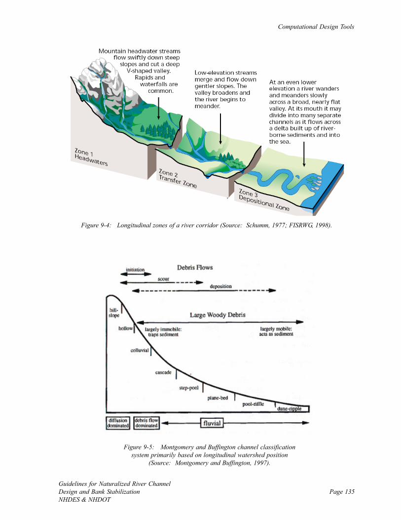
Computational Design Tools
Guidelines for Naturalized River ChannelDesign and Bank StabilizationNHDES & NHDOT
Page 135
Figure 9-5: Montgomery and Buffington channel classificationsystem primarily based on longitudinal watershed position
(Source: Montgomery and Buffington, 1997).
Figure 9-4: Longitudinal zones of a river corridor (Source: Schumm, 1977; FISRWG, 1998).

Chapter 9.0
Guidelines for Naturalized River ChannelDesign and Bank Stabilization
NHDES & NHDOTPage 136
Figu
re 9
-6:
Ros
gen
chan
nel c
lass
ifica
tion
syst
em b
ased
on
slop
e, s
inuo
sity,
wid
th to
dep
th r
atio
, ent
renc
hmen
tra
tio, a
nd d
omin
ant b
ed m
ater
ial (
Sour
ce:
Rosg
en, 1
994;
Ros
gen
and
Silv
ey, 1
996)
.
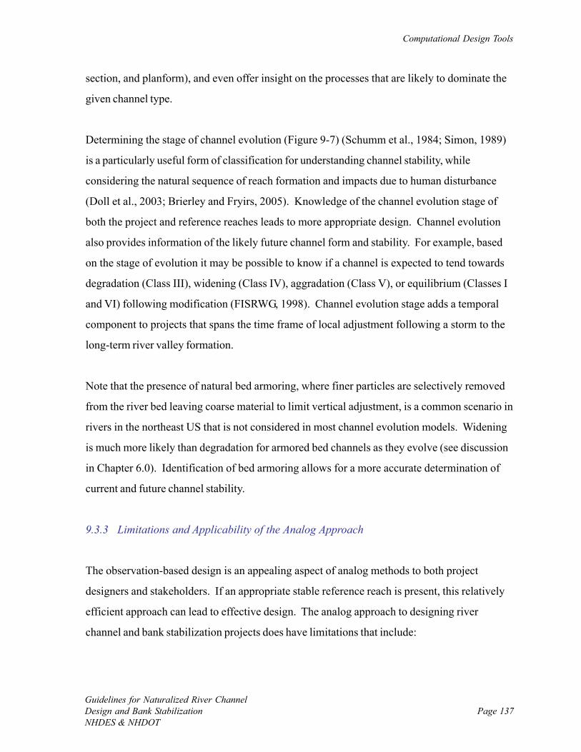
Computational Design Tools
Guidelines for Naturalized River ChannelDesign and Bank StabilizationNHDES & NHDOT
Page 137
section, and planform), and even offer insight on the processes that are likely to dominate the
given channel type.
Determining the stage of channel evolution (Figure 9-7) (Schumm et al., 1984; Simon, 1989)
is a particularly useful form of classification for understanding channel stability, while
considering the natural sequence of reach formation and impacts due to human disturbance
(Doll et al., 2003; Brierley and Fryirs, 2005). Knowledge of the channel evolution stage of
both the project and reference reaches leads to more appropriate design. Channel evolution
also provides information of the likely future channel form and stability. For example, based
on the stage of evolution it may be possible to know if a channel is expected to tend towards
degradation (Class III), widening (Class IV), aggradation (Class V), or equilibrium (Classes I
and VI) following modification (FISRWG, 1998). Channel evolution stage adds a temporal
component to projects that spans the time frame of local adjustment following a storm to the
long-term river valley formation.
Note that the presence of natural bed armoring, where finer particles are selectively removed
from the river bed leaving coarse material to limit vertical adjustment, is a common scenario in
rivers in the northeast US that is not considered in most channel evolution models. Widening
is much more likely than degradation for armored bed channels as they evolve (see discussion
in Chapter 6.0). Identification of bed armoring allows for a more accurate determination of
current and future channel stability.
9.3.3 Limitations and Applicability of the Analog Approach
The observation-based design is an appealing aspect of analog methods to both project
designers and stakeholders. If an appropriate stable reference reach is present, this relatively
efficient approach can lead to effective design. The analog approach to designing river
channel and bank stabilization projects does have limitations that include:
Chapter 9.0
Guidelines for Naturalized River ChannelDesign and Bank Stabilization
NHDES & NHDOTPage 138
Figure 9-7: A schematic of the Simon incised channel evolutionmodel (Source: Simon, 1989; FISRWG, 1998).
Computational Design Tools
Guidelines for Naturalized River ChannelDesign and Bank StabilizationNHDES & NHDOT
Page 139
• Reference reaches are often difficult to find in disturbed systems leading to guesswork
in the fundamental component of the design approach;
• Reliance on a single design flow, typically the bankfull discharge which can be difficult
to identify, limits designs and increases the chances of project failure;
• The determination of dominant particle size is not always straight forward and
complicates channel classification;
• Channel form (i.e., profile, cross section, and planform) alone does not always serve as
a good predictor of system processes such as disturbance, response and sediment
transport (Simon et al., 2005); and
• Reference reach data have to be adjusted for watershed scale.
As with the empirical, the analog approach is a useful method to be used with other
computational tool. Specifically, hydraulic modeling is recommended with the analog
approach to expand the understanding of the physical processes and anticipated response to
project implementation that is not possible from analog methods alone. The combination of
analog and analytical computational tools is referred to as “the geomorphic engineering
approach” (Soar and Thorne, 2001), and is an effective design strategy for moderate and
comprehensive projects.
9.4 Analytical Techniques
9.4.1 Introduction
Analytical, or physical-based, techniques have played a key role in both historic and recent
engineering methods of naturalized river channel design and bank stabilization. Common
analytical techniques include basic calculations using the Manning’s and continuity equations,
hydraulic modeling, and channel stability and sediment transport analysis.
Chapter 9.0
Guidelines for Naturalized River ChannelDesign and Bank Stabilization
NHDES & NHDOTPage 140
9.4.2 Basic Hydraulics
The fundamentals of hydraulics include simple physical-based analytical techniques used to
relate water velocity, discharge, and dimensions of open channels (Chanson, 2004). The
continuity equation Q=VA indicates that discharge (Q, cfs) is equal to the product of mean
water velocity (V, fps) and cross sectional area (A, sq ft). Without inflow, outflow, or changes
in storage, discharge is constant between cross sections (Q1=V1A1=V2A2=Q2). This
relationship is widely used when considering changes in water velocity, and thus sediment
transport capacity, following changes in channel dimensions. For a given discharge, increases
in cross sectional area lead to a decrease in mean water velocity, while decreases in cross
sectional area lead to increased mean velocity.
Assuming uniform flow, or simple flow parallel to the river bed where the magnitude and
direction of velocity is the same at every point, mean water velocity (V, fps) is calculated
using Manning’s equation V=(1.49/N)R2/3S1/2. N is the Manning’s roughness coefficient and is
a product of the bed particle size, type of debris present, and condition of the channel and can
be determined with guidance from many existing manuals and texts that address open channel
flow (FISRWG, 1998; USACOE, 2005; Arcement and Schneider, 2006) and at several
Internet sites (http://www.utdallas.edu/~brikowi/Teaching/Applied_Modeling/SurfaceWater/
LectureNotes/Manning_Roughness/ and http://wwwrcamnl.wr.usgs.gov/sws/fieldmethods/
Indirects/nvalues/). R (ft) is the hydraulic radius that is equal to the cross sectional flow area
(sq ft) divided by the wetted perimeter of the channel (ft). S is the channel slope (ft/ft). Mean
discharge (Q, cfs), assuming uniform flow, can be determined by combining the Manning’s and
continuity equations Q = A(1.49/N)R2/3S1/2. Following field measurements of channel
dimensions based on low, bankfull, and high flow indicators, one estimate of design flows is
obtained.
Computational Design Tools
Guidelines for Naturalized River ChannelDesign and Bank StabilizationNHDES & NHDOT
Page 141
9.4.3 Hydraulic Modeling
Hydraulic modeling is commonly employed to represent the more realistic scenario of non-
uniform flow, where flow paths are locally variable due to contractions and expansions and
small-scale features. Non-uniform water velocity is determined by flow energy according to
the Bernoulli equation E=Y+V2/2g. The depth (Y) is the potential energy component and V2/
2g is the kinetic energy component where V is the water velocity and g is the acceleration of
gravity constant. The energy is minimal at critical flow conditions, where critical depth and
velocity occur. There are two important states of gradual varied flow – subcritical and
supercritical. Subcritical flow occurs when the depth is larger than the critical depth and flow
is slow and tranquil (Chanson, 2004). Under subcritical flow, water depth will decrease if the
river bed is raised and will increase if the bed is lowered. Supercritical flow, on the other
hand, occurs when the water depth is less than the critical depth and flow is fast and torrential.
(Chanson, 2004). Under supercritical flow, water depth will increase if the river bed is raised,
and depth will decrease if the bed is lowered.
Hydraulic modeling is used to compute water surface profiles and associated variables at cross
sections in the project river. The most widely used and recommended hydraulics model for
naturalized river channel design and bank stabilization projects is HEC-RAS (USACOE,
2005). This one-dimensional simulation of gradually varied flow can be run in both steady
(i.e., flow is constant with time) and unsteady modes. Steady flow is used when the peak of
different design flows are used to simulate hydrology and is recommended for moderate
projects. Unsteady flows are used for more involved comprehensive projects where a full
input hydrograph is generated and hydraulic conditions are analyzed over the course of a
storm in addition to at the peak flow. HEC-RAS can accommodate a full dendritic network
of channels or a single river reach. Water surface profiles can be determined for subcritical,
supercritical, and mixed-flow conditions. The basic computational procedure of HEC-RAS is
solution of the one-dimensional Bernoulli equation. Energy losses are evaluated by the
Manning’s equation. The momentum equation (fundamentally the product of water mass and
Chapter 9.0
Guidelines for Naturalized River ChannelDesign and Bank Stabilization
NHDES & NHDOTPage 142
velocity) is used in limited situations where the water surface profile is rapidly varied, such as
at culverts, bridges, dams, and confluences.
Hydraulic modeling with HEC-RAS typically includes the following steps:
• Determining peak flow rates or hydrographs for the range of design flows;
• Setting up system geometry based on recent or previous survey information, or
approximated cross sectional geometry obtained from topographic maps and field
measurements of channel dimensions;
• Setting appropriate boundary conditions; and
• Running several different analysis plans to investigate existing conditions and
recommended alternatives.
Additional information on the details of using HEC-RAS can be obtained from the user’s
manual and hydraulic reference that come with the public-domain software that can be
obtained from the Internet (http://www.hec.usace.army.mil/software/hec-ras/), second-party
guidance documents and texts, and professional courses. There is an art to HEC-RAS
modeling that takes time and experience to develop.
Standard HEC-RAS outputs include discharge, channel thalweg elevation, water surface
elevation, critical water surface elevation, energy grade line elevation, energy grade slope,
water velocity, cross sectional flow area, top width of flow, and the Froude number. In
addition, a wide range of other hydraulic variables are calculated at each cross section.
The results of HEC-RAS hydraulic modeling are useful for completing a range of tasks
associated with river channel design and bank stabilization projects. Investigating changes in
water surface elevation and flow characteristics proposed after project implementation;
iteratively adjusting channel dimensions to reach desired flow characteristics; determining the
elevation to place structural components; and investigating a local project in the context of
hydraulics of a larger reach, river, or watershed are some of the many common applications.
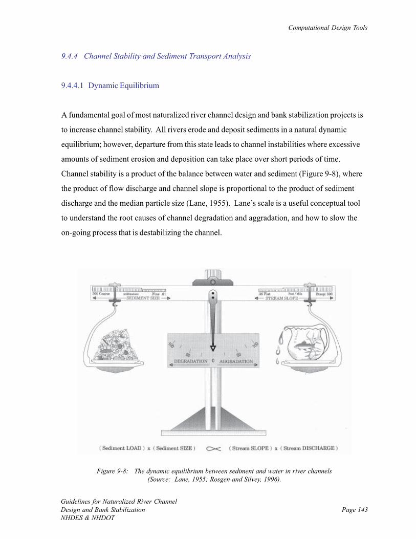
Computational Design Tools
Guidelines for Naturalized River ChannelDesign and Bank StabilizationNHDES & NHDOT
Page 143
Figure 9-8: The dynamic equilibrium between sediment and water in river channels(Source: Lane, 1955; Rosgen and Silvey, 1996).
9.4.4 Channel Stability and Sediment Transport Analysis
9.4.4.1 Dynamic Equilibrium
A fundamental goal of most naturalized river channel design and bank stabilization projects is
to increase channel stability. All rivers erode and deposit sediments in a natural dynamic
equilibrium; however, departure from this state leads to channel instabilities where excessive
amounts of sediment erosion and deposition can take place over short periods of time.
Channel stability is a product of the balance between water and sediment (Figure 9-8), where
the product of flow discharge and channel slope is proportional to the product of sediment
discharge and the median particle size (Lane, 1955). Lane’s scale is a useful conceptual tool
to understand the root causes of channel degradation and aggradation, and how to slow the
on-going process that is destabilizing the channel.
Chapter 9.0
Guidelines for Naturalized River ChannelDesign and Bank Stabilization
NHDES & NHDOTPage 144
9.4.4.2 Threshold Velocity and Critical Shear Stress (Incipient Motion)
The ability of flowing water to dislodge and transport individual sediment particles is a
function of the ratio between the hydraulic shear stress and the particle’s resistance to motion.
Shear stress is directly related to water velocity. Channel stability and the likelihood of
erosion or deposition can be determined by calculating critical shear stress – the minimum
stress required to initiate motion of a particle of a given size, or threshold velocity – the
minimum water velocity required to move a particle of a given size. Erosion is likely to occur
at a cross section if the local shear stress (or mean water velocity) is larger than the critical
shear stress (or threshold velocity) and deposition is anticipated at a cross section if the local
shear stress (or mean water velocity) is smaller than critical (or threshold) levels. Calculated
estimates of critical shear stress and threshold velocity exist for both different sized soil
particles and materials used in naturalized channel design and bank stabilization projects
(Table 9-2). Direct shear stress calculations can get complicated and thus are reserved for
moderate and comprehensive projects where computer hydraulic modeling is performed.
Approximating channel stability based on threshold velocity calculations is ample for most
routine projects and some moderate projects.
There are numerous ways to estimate threshold velocity for comparison to mean velocity as
determined from Manning’s equation or an existing empirical relationship. Particle size
distribution is required to use the many existing simple relationships (Table 9-3A) or charts
(Appendix F) to calculate threshold velocity. As most of these relationships were derived
from experiments in flumes and only approximate conditions in natural river channels, it is
best to calculate several estimates and compare results. Note that the basic equations are
empirically derived and thus units do not follow typical calculation rules. Be aware that some
diagrams portray critical velocity (or shear stress) in dimensionless forms, which is commonly
noted by an asterisk subscript.
Simple relationships also exist for estimating critical shear stress that are a function of the
particle size distribution (Table 9-3B) for comparison to shear stress calculations at a cross
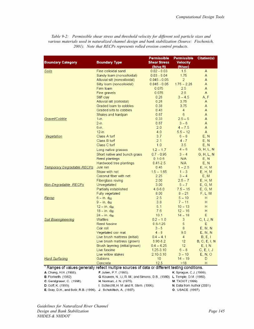
Computational Design Tools
Guidelines for Naturalized River ChannelDesign and Bank StabilizationNHDES & NHDOT
Page 145
Table 9-2: Permissible shear stress and threshold velocity for different soil particle sizes andvarious materials used in naturalized channel design and bank stabilization (Source: Fischenich,
2001). Note that RECPs represents rolled erosion control products.
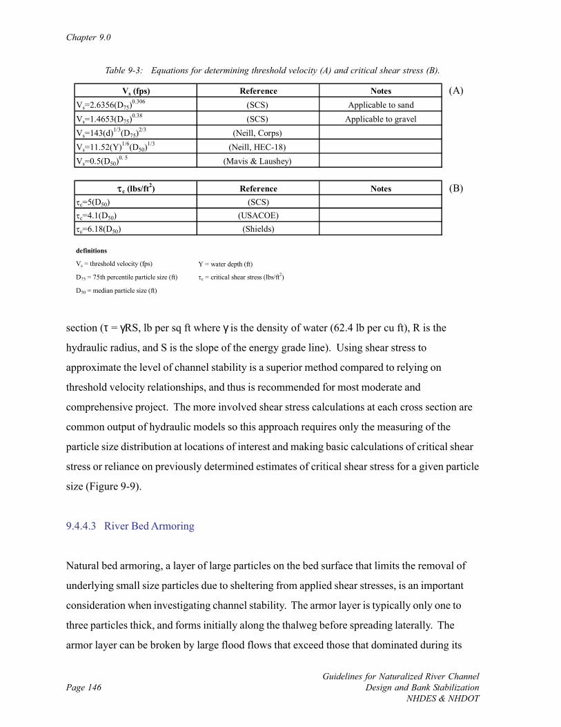
Chapter 9.0
Guidelines for Naturalized River ChannelDesign and Bank Stabilization
NHDES & NHDOTPage 146
Vs (fps) Reference Notes (A)Vs=2.6356(D75)
0.306 (SCS) Applicable to sandVs=1.4653(D75)
0.38 (SCS) Applicable to gravelVs=143(d)1/3(D75)
2/3 (Neill, Corps) Vs=11.52(Y)1/6(D50)
1/3 (Neill, HEC-18) Vs=0.5(D50)
0. 5 (Mavis & Laushey)
τc (lbs/ft2) Reference Notes (B)τc=5(D50) (SCS)τc=4.1(D50) (USACOE)τc=6.18(D50) (Shields)
definitions
Vs = threshold velocity (fps) Y = water depth (ft)
D75 = 75th percentile particle size (ft) τc = critical shear stress (lbs/ft2)
D50 = median particle size (ft)
Table 9-3: Equations for determining threshold velocity (A) and critical shear stress (B).
section (τ = γRS, lb per sq ft where γ is the density of water (62.4 lb per cu ft), R is the
hydraulic radius, and S is the slope of the energy grade line). Using shear stress to
approximate the level of channel stability is a superior method compared to relying on
threshold velocity relationships, and thus is recommended for most moderate and
comprehensive project. The more involved shear stress calculations at each cross section are
common output of hydraulic models so this approach requires only the measuring of the
particle size distribution at locations of interest and making basic calculations of critical shear
stress or reliance on previously determined estimates of critical shear stress for a given particle
size (Figure 9-9).
9.4.4.3 River Bed Armoring
Natural bed armoring, a layer of large particles on the bed surface that limits the removal of
underlying small size particles due to sheltering from applied shear stresses, is an important
consideration when investigating channel stability. The armor layer is typically only one to
three particles thick, and forms initially along the thalweg before spreading laterally. The
armor layer can be broken by large flood flows that exceed those that dominated during its
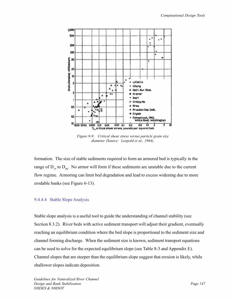
Computational Design Tools
Guidelines for Naturalized River ChannelDesign and Bank StabilizationNHDES & NHDOT
Page 147
Figure 9-9: Critical shear stress versus particle grain sizediameter (Source: Leopold et al., 1964).
formation. The size of stable sediments required to form an armored bed is typically in the
range of D75 to D90. No armor will form if these sediments are unstable due to the current
flow regime. Armoring can limit bed degradation and lead to excess widening due to more
erodable banks (see Figure 6-13).
9.4.4.4 Stable Slope Analysis
Stable slope analysis is a useful tool to guide the understanding of channel stability (see
Section 8.3.2). River beds with active sediment transport will adjust their gradient, eventually
reaching an equilibrium condition where the bed slope is proportional to the sediment size and
channel forming discharge. When the sediment size is known, sediment transport equations
can be used to solve for the expected equilibrium slope (see Table 8-3 and Appendix E).
Channel slopes that are steeper than the equilibrium slope suggest that erosion is likely, while
shallower slopes indicate deposition.
Chapter 9.0
Guidelines for Naturalized River ChannelDesign and Bank Stabilization
NHDES & NHDOTPage 148
9.4.4.5 Stable Channel Dimensions with HEC-RAS
Stable channel dimensions can be estimated in HEC-RAS using the Copeland, Blench Regime,
or Tractive Force methods. Refer to the HEC-RAS Hydraulics Reference Manual for
additional details on theory and application. The output for each of these algorithms is
channel width, depth, and slope. The definition of stability is a function of which method is
used. For Copeland’s (1994) method, stability is achieved when sediment inflow equals
sediment outflow. Output from this model includes stability curves of width and depth versus
slope, including indications of when aggradation and degradation may occur. In addition, the
width and depth associated with the minimum stream power solution, or the minimum slope
that will transport the incoming sediment, is computed. The Copeland method is primarily
used for sand bed channels.
Regime methods are empirically-based and stability is present when no net annual erosion or
deposition occurs. The Blench Regime method (Blench, 1970) used in HEC-RAS is
appropriate for sand bed channels. If the channel can be approximated by this and other
suggested application criteria, this is a quick way to get stable channel dimension estimates.
Tractive force methods consider a channel stable when there is no net movement of particles
on the bed. Critical shear stress is used to assess if the channel is prone to degradation or
aggradation, or is in equilibrium. Methods by both Lane (1953) and Shields (Shields, 1936)
for determining the initiation of motion, in addition to a user entered critical value are
available. The tractive force approach to estimating stable channel dimensions is applicable to
channels with substrates that are more coarse than sand.
9.4.4.6 Sediment Transport Analysis in HEC-RAS
The potential sediment transport capacity is calculated based on hydraulics and the particle
size distribution for a given reach. The primary outputs of the analysis are a sediment rating
curve, or sediment capacity (tons/day) versus flow (cfs) at a cross section, and a sediment
Computational Design Tools
Guidelines for Naturalized River ChannelDesign and Bank StabilizationNHDES & NHDOT
Page 149
profile, or sediment capacity (tons/day) versus main channel distance (ft). The rating curve is
useful for understanding the capacity at a given cross section, while the rating curve
represents the continuity of sediment transport. If sediment transport capacity drops in
successive reaches deposition is expected, whereas if transport increases erosion is expected.
There are a wide range of sediment transport functions that have a major influence on results,
and selecting the appropriate method to determine sediment transport capacity is one of the
central challenges with the analysis. A review of the many sediment transport equations is
beyond the scope of this guidelines document, and one can refer to the HEC-RAS Hydraulics
Reference Manual for a summary of theory and application notes of several of the more
common formulae. The most common methods used are those by Meyer-Peter Müeller and
Yang. The Meyer-Peter Müeller equation is valid for sands and gravels, and transport rate is
determined from the difference between the mean and critical shear stresses. Yang’s method is
applicable for silts, sands, and fine gravels, and transport rate is primarily a function of stream
power.
Although there is an extensive body of research and many application methods on sediment
transport analysis, the typical wide range of results originating from different methods
suggests that there currently is no clear single way to approximate sediment transport. A
comparative approach is recommended where several methods that are applicable to the
project site are used and findings are checked for consistency. In addition, the sediment
transport scenario should be checked with respect to the geomorphic analysis to see if findings
make physical sense. Finally, and ideally, verification via field measurements in the project
watershed or region is useful for strengthening modeling results.
9.4.5 Limitations and Applicability of the Analytical Approach
The ability to model designs with both spatial and temporal dynamics is a primary advantage
of using analytical techniques for naturalized river channel design and bank stabilization
projects that is not available via other computation methods. A variety of useful computer
Chapter 9.0
Guidelines for Naturalized River ChannelDesign and Bank Stabilization
NHDES & NHDOTPage 150
programs are available through both public domain and private software distributors to readily
perform a variety of computations. Once models are set up, existing conditions and a range of
alternatives can typically be run over short periods of time.
There are some limitations to analytical methods that include:
• Even with guidance materials, some up front research and experience is necessary to
accurately select and use each variable, equation, and model parameter;
• Equations and numerical analytical tools can appear abstract to the public, and thus
they are often not as readily digestible by project stakeholders as compared to more
visual approaches;
• Setting up and debugging large computer models takes time, and thus can increase
project costs; and
• Fundamentally, there are insufficient physical equations to generate an analytical
solution when modeling a natural river channel that can have up to nine degrees of
freedom (variables) (Hey and Thorne, 1986), and thus empirical or analog methods are
also needed. The independent variables are usually watershed area, dominant
discharge, and sediment load. The dependent variables are channel width, depth,
slope, sinuosity, substrate, and bank slope.
Page 151Guidelines for Naturalized River ChannelDesign and Bank StabilizationNHDES & NHDOT
CHAPTER 10.0: COMMON CHANNEL AND BANK PRACTICES
10.1 Introduction
Installation of channel and bank practices is necessary when the ‘do nothing’ or passive
approaches to naturalized river channel design and bank stabilization projects are not enough
to establish suitably stable boundary conditions based on site constraints, improve aquatic
habitat and meet other goals. A variety of practices using both hard and soft materials can be
used to stabilize the bed (i.e., establish grade control), stabilize banks, enhance habitat, and
improve riparian vegetation. Soft materials such as natural vegetation and fiber rolls and mats
are preferable from a habitat point of view, but are not always appropriate due to site
characteristics and constraints requiring a more rigid design. In these situations, a
combination of hard and soft materials is the best approach to achieve the desired channel and
bank stability, and maintain some natural habitat features of the river.
Channel and bank practices have been used for decades to improve river conditions and thus
existing manuals offer a lot of useful information on application details. Table 10-1 organizes
common practices by their application, and lists the appropriate references for design
information. Some manuals (e.g., FISRWG, 1998) primarily offer general guidance on what a
particular practice is useful for and where it is most applicable. Other manuals (e.g., MDE,
2000; Eubanks and Meadows, 2002) offer construction guidelines that include uses and
limitations, material specifications, approximate costs, installation guidelines, and detailed
schematics. Other manuals (e.g., NRCS, 2005) provide additional theory and detailed design
guidance. Note that all of the references that are available for public use are assembled in the
accompanying electronic library for quick access while using this guidelines document.
Choosing the appropriate practices primarily is a function of using materials that have
threshold velocities that are suitable for the site conditions and their planned location of
installation (Fischenich, 2001), accomplish project goals and objectives and allow for the most
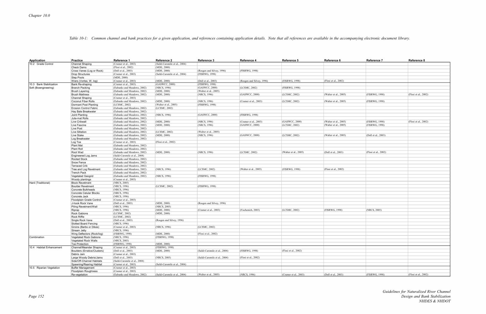
Chapter 10.0
Page 152Guidelines for Naturalized River Channel
Design and Bank StabilizationNHDES & NHDOT
Application Practice Reference 1 Reference 2 Reference 3 Reference 4 Reference 5 Reference 6 Reference 7 Reference 810.2 Grade Control Channel Shaping (Cramer et al., 2003) (Saldi-Caromile et al., 2004)
Check Dams (Flosi et al., 2002) (MDE, 2000)Cross Vanes (Log or Rock) (Doll et al., 2003) (MDE, 2000) (Rosgen and Silvey, 1996) (FISRWG, 1998)Drop Structures (Cramer et al., 2003) (Saldi-Caromile et al., 2004) (FISRWG, 1998)Step Pools (MDE, 2000)Wiers (Vortex, W, log) (Cramer et al., 2003) (MDE, 2000) (Doll et al., 2003) (Rosgen and Silvey, 1996) (FISRWG, 1998) (Flosi et al., 2002)
10.3 Bank Stabilization Bank Re-shaping (Cramer et al., 2003) (GASWCC, 2000) (FISRWG, 1998)Soft (Bioengineering) Branch Packing (Eubanks and Meadows, 2002) (NRCS, 1996) (GASWCC, 2000) (LCSMC, 2002) (FISRWG, 1998)
Brush Layering (Eubanks and Meadows, 2002) (MDE, 2000) (Walter et al., 2005)Brush Mattress (Eubanks and Meadows, 2002) (MDE, 2000) (NRCS, 1996) (GASWCC, 2000) (LCSMC, 2002) (Walter et al., 2005) (FISRWG, 1998) (Flosi et al., 2002)Channel Shaping (Cramer et al., 2003)Coconut Fiber Rolls (Eubanks and Meadows, 2002) (MDE, 2000) (NRCS, 1996) (Cramer et al., 2003) (LCSMC, 2002) (Walter et al., 2005) (FISRWG, 1998)Dormant Post Planting (LCSMC, 2002) (Walter et al., 2005) (FISRWG, 1998)Erosion Control Fabric (Eubanks and Meadows, 2002) (LCSMC, 2002)Hay Bale Breakwater (Eubanks and Meadows, 2002)Joint Planting (Eubanks and Meadows, 2002) (NRCS, 1996) (GASWCC, 2000) (FISRWG, 1998)Jute-mat Rolls (Eubanks and Meadows, 2002)Live Cribwall (Eubanks and Meadows, 2002) (MDE, 2000) (NRCS, 1996) (Cramer et al., 2003) (GASWCC, 2000) (Walter et al., 2005) (FISRWG, 1998) (Flosi et al., 2002)Live Fascine (Eubanks and Meadows, 2002) (MDE, 2000) (NRCS, 1996) (GASWCC, 2000) (LCSMC, 2002) (Walter et al., 2005) (FISRWG, 1998)Live Post (Eubanks and Meadows, 2002)Live Siltation (Eubanks and Meadows, 2002) (LCSMC, 2002) (Walter et al., 2005)Live Stake (Eubanks and Meadows, 2002) (MDE, 2000) (NRCS, 1996) (GASWCC, 2000) (LCSMC, 2002) (Walter et al., 2005) (Doll et al., 2003)Log Breakwater (Eubanks and Meadows, 2002)Log Toe (Cramer et al., 2003) (Flosi et al., 2002)Plant Mat (Eubanks and Meadows, 2002)Plant Roll (Eubanks and Meadows, 2002)Root Wad (Eubanks and Meadows, 2002) (MDE, 2000) (NRCS, 1996) (LCSMC, 2002) (Walter et al., 2005) (Doll et al., 2003) (Flosi et al., 2002)Engineered Log Jams (Saldi-Caromile et al., 2004) Rooted Stock (Eubanks and Meadows, 2002)Snow Fence (Eubanks and Meadows, 2002)Terraced Crib (Eubanks and Meadows, 2002)Tree and Log Revetment (Eubanks and Meadows, 2002) (NRCS, 1996) (LCSMC, 2002) (Walter et al., 2005) (FISRWG, 1998) (Flosi et al., 2002)Trench Pack (Eubanks and Meadows, 2002)Vegetated Geogrid (Eubanks and Meadows, 2002) (NRCS, 1996) (FISRWG, 1998)Woody plantings (Cramer et al., 2003)
Hard (Traditional) Block Revetment (NRCS, 2005)Boulder Revetment (NRCS, 1996) (LCSMC, 2002) (FISRWG, 1998)Concrete Bulkheads (NRCS, 1996)Concrete Celular Blocks (NRCS, 1996)Concrete Jack (NRCS, 1996)Floodplain Grade Control (Cramer et al., 2003)J-hook Rock Vane (Doll et al., 2003) (MDE, 2000) (Rosgen and Silvey, 1996)Piling Revetment/Wall (NRCS, 1996) (NRCS, 2005)Riprap (NRCS, 1996) (MDE, 2000) (Cramer et al., 2003) (Fischenich, 2003) (LCSMC, 2002) (FISRWG, 1998) (NRCS, 2005)Rock Gabions (LCSMC, 2002) (MDE, 2000)Rock Riffle (LCSMC, 2002)Single Rock Vane (Doll et al., 2003) (Rosgen and Silvey, 1996)Slotted Board Fencing (NRCS, 1996)Groins (Barbs or Dikes) (Cramer et al., 2003) (NRCS, 1996) (LCSMC, 2002)Stream Jetty (NRCS, 1996)Wing Deflectors (Rock/log) (FISRWG, 1998) (MDE, 2000) (Flosi et al., 2002)
Combination Vegetated Rock Gabions (NRCS, 1996) (FISRWG, 1998)Vegetated Rock Walls (NRCS, 2005)Toe Protection (FISRWG, 1998) (MDE, 2000)
10.4 Habitat Enhancement Channel/Meander Shaping (Cramer et al., 2003) (FISRWG, 1998)Boulders (Erratics/Clusters) (Doll et al., 2003) (MDE, 2000) (Saldi-Caromile et al., 2004) (FISRWG, 1998) (Flosi et al., 2002)Debris Jam (Cramer et al., 2003)Large Woody Debris/Jams (Doll et al., 2003) (NRCS, 2005) (Saldi-Caromile et al., 2004) (Flosi et al., 2002)Side/Off-Channel Habitats (Saldi-Caromile et al., 2004) Spawning/Rearing Habitat (Cramer et al., 2003) (Saldi-Caromile et al., 2004)
10.5 Riparian Vegetation Buffer Management (Cramer et al., 2003)Floodplain Roughness (Cramer et al., 2003)Re-vegetation (Eubanks and Meadows, 2002) (Saldi-Caromile et al., 2004) (Walter et al., 2005) (NRCS, 1996) (Cramer et al., 2003) (Doll et al., 2003) (FISRWG, 1998) (Flosi et al., 2002)
Table 10-1: Common channel and bank practices for a given application, and references containing application details. Note that all references are available in the accompanying electronic document library.
Common Channel and Bank Practices
Guidelines for Naturalized River ChannelDesign and Bank StabilizationNHDES & NHDOT
Page 153
ecological recovery possible. Application guidance exists for practices (Tables 10-2 and 10-
3), and the uniqueness of each site often allows, if not requires, different combinations of
practices in different locations. The following general questions can help with the appropriate
selection of practices.
• Could the problem be addressed with a ‘no action’ or passive approach, or is an
installed practice required?
• Will the practice be stable in the near future given the estimated water velocities on the
bed; low, mid and upper bank; and adjacent buffer during overbank floods?
• Is the practice over-sized relative to naturally occurring habitat features in the project
reach, which could inadvertently degrade habitat during low flows?
• What is the expected lifetime of the practice and is that ample for its objective?
• Is the practice treating the source or response of a problem, and is that appropriate
given the lifetime of the project?
• What are the ecological benefits and risks associated with the practice?
• Will the practice result in unintended effects at the site, along the reach, or on nearby
properties?
10.2 Grade Control
10.2.1 Introduction
Grade control structures are used to stabilize the elevation of the river bed. Vertical channel
degradation, or incision, can occur due to the upstream migration of a nick point during
channel evolution (Schumm et al., 1984; FISRWG, 1998). This incision process can be
accelerated by adjustment of the balance between sediment and water in a river channel (Lane,
1955), and disturbance such as channelization (Simon, 1989; Doll et al., 2003).
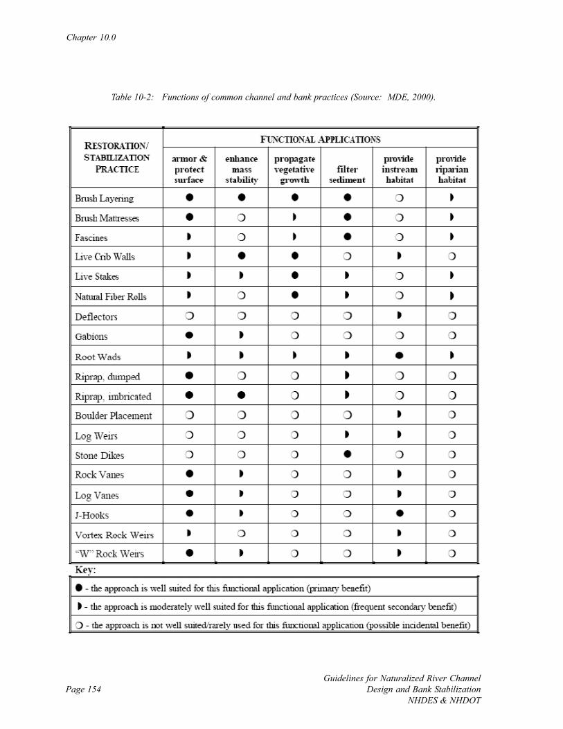
Chapter 10.0
Guidelines for Naturalized River ChannelDesign and Bank Stabilization
NHDES & NHDOTPage 154
Table 10-2: Functions of common channel and bank practices (Source: MDE, 2000).
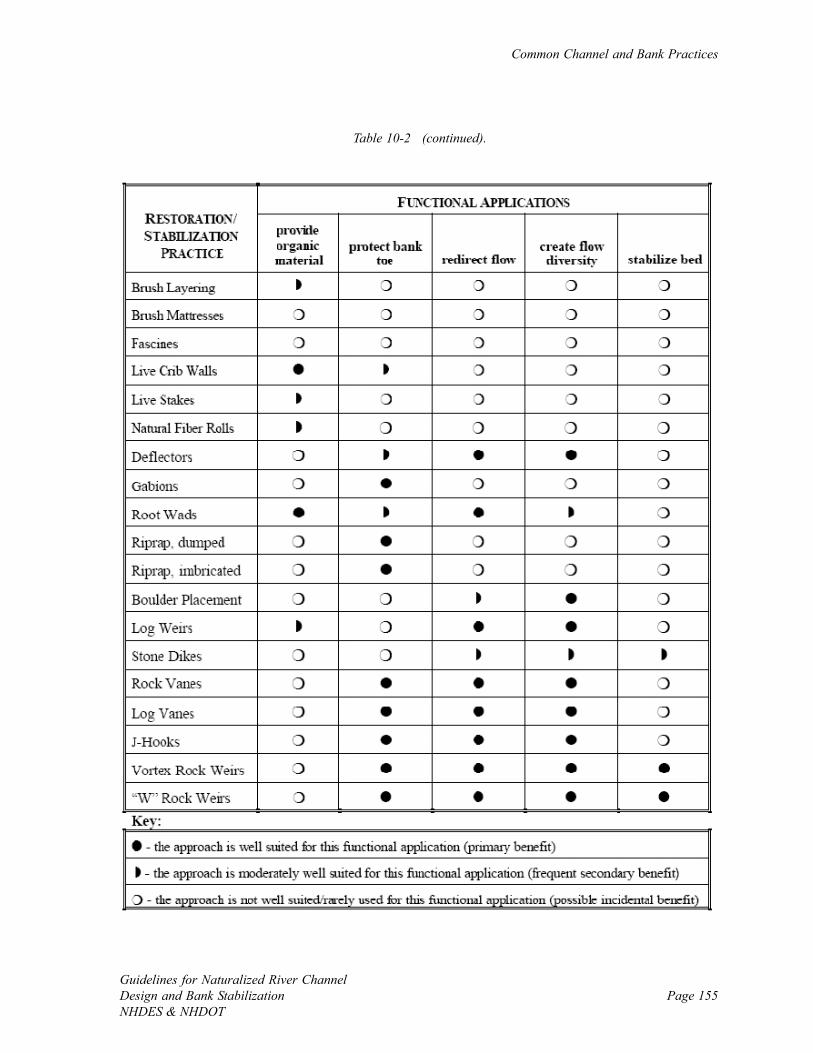
Common Channel and Bank Practices
Guidelines for Naturalized River ChannelDesign and Bank StabilizationNHDES & NHDOT
Page 155
Table 10-2 (continued).
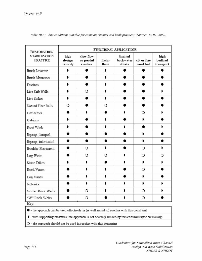
Chapter 10.0
Guidelines for Naturalized River ChannelDesign and Bank Stabilization
NHDES & NHDOTPage 156
Table 10-3: Site conditions suitable for common channel and bank practices (Source: MDE, 2000).

Common Channel and Bank Practices
Guidelines for Naturalized River ChannelDesign and Bank StabilizationNHDES & NHDOT
Page 157
Table 10-3 (continued).
Chapter 10.0
Guidelines for Naturalized River ChannelDesign and Bank Stabilization
NHDES & NHDOTPage 158
Selection of grade control structures is closely linked to the equilibrium bed slope (see Section
8.3.2) bed particle size, the existing bed stability, and the severity of the system conditions. In
addition, it is helpful to know the current stage of channel evolution (see Figure 9-7), and if
degradation, aggradation or widening are taking place due to changes in sediment transport
(see Figure 6-13).
10.2.2 Common Grade Control Practices
Weirs, drop structures, cross vanes, and check dams are typically used for grade control. On
smaller rivers these practices essentially create step-pools, while on larger rivers they result in
the creation of a local scour hole. In both cases, successful installation creates a vertical
control that stops additional degradation of the bed. In addition to structural elements,
channel shaping is used on occasion to adjust channel form to stabilize the river bed.
Grade control structures on smaller rivers can be made of logs or large boulders, while large
boulders are almost exclusively used on larger rivers. Certain structures such as V- (medium-
sized rivers) and W-weirs (large rivers) direct flow away from the banks as well. Check dams
and step-pool creation are grade control practices that are typically more applicable for
medium to small rivers.
Important design considerations for grade control structures include the bottom and top
installation elevations of the practice (top at the outside of the channel at bankfull level and
bottom around the middle of the channel near the channel invert), how the structure is tied
into the bed and banks (tight fit, 20-30 degrees upstream), local hydraulics that will exist over
a range of flows around the structure (scour pool and plunging flow), and the anticipated
longevity of the installation. Where bed or banks are composed of erodable fine materials
such as sands and silts, undermining and dislocation is possible. Be sure that the material
under the river bed can support heavy materials, and machinery used to transport them into
place, before beginning installation. Information on previous projects is a good source of
information on what has and has not worked.
Common Channel and Bank Practices
Guidelines for Naturalized River ChannelDesign and Bank StabilizationNHDES & NHDOT
Page 159
A common pitfall of grade control structures is creating fish blocks during low and moderate
flows if structures are over-built. Careful attention to the material size and vertical location of
installation relative to different flows can avoid this common habitat impairment. When
unsure about the applicability or construction details of a practice, walk the river channel and
try to observe and photograph natural features that the practice is trying to mimic. When
doing so, keep in mind that some natural features can fragment aquatic habitat.
10.3 Bank Stabilization
10.3.1 Introduction
River banks become unstable and erode due to general bank scour, undercutting, or localized
scour (GASWCC, 2000). General bank scour is the widespread erosion of streambanks
caused by excessive mean water velocity impinging on the bank. Undercutting, or removal of
the submerged low bank (i.e., the toe), is one of the most common modes of river bank
failure. Some level of undercutting occurs on the outside of most meander bends, and when
excessive usually leads to subsequent collapse of the mid and upper bank. A challenge when
contemplating the extent of bank stabilization projects is separating out locations that are
undergoing normal levels of scour for the system versus excessive undercutting erosion. Field
observations are used to identify localized scour where only isolated sections of eroding banks
occur in otherwise stable reaches. Common signs of excessive erosion include large bank
areas that do not have vegetation and appear to be sliding or caving in, and slumping
vegetation at the top of bank. Bank erosion can also originate from landslides adjacent to the
river channel, or an avulsion where the river rapidly changes its flow path via erosion of a new
channel.
Another important mode of river bank erosion in the northeast United States is destabilization
due to annual or more frequent freeze-thaw cycles, and physical abrasion due to ice rafting
during spring ice out (Watson et al., 1999). Ice often leads to increased flow depths, and

Chapter 10.0
Guidelines for Naturalized River ChannelDesign and Bank Stabilization
NHDES & NHDOTPage 160
excessive scour of the low bank in channels with deformable banks (Ettema, 2002). Designs
must consider the range of forces acting on the bank due to winter ice, especially in locations
such as large meanders, natural contractions, or bridge crossings where ice jams tend to occur.
Ice can lead to substantial changes to a river channel, especially when there is a large flood
while the river is still covered by ice. Large amounts of material can be removed from the
banks, and channel depth and thalweg location often change. Whether the channel changes
due to winter ice are temporary or permanent, a variation in the hydraulic forces acting on the
low bank and channel bed take place and should be considered when selecting practices for
naturalized channel design and bank stabilization projects.
There are many factors that influence bank erodability. The Bank Erodability Hazard Index
(BEHI) (Rosgen and Silvey, 1996) ranks bank stability based on (1) the ratio of bank height to
bankfull height, (2) the ratio of vegetative-rooting depth to bank height, (3) the density of
roots, (4) the streambank angle and (5) the vegetative bank protection. Coupled with the
bank particle size and cohesiveness, these factors, along with the localized hydrology around
the bank (i.e., seeps, evapotranspiration, canopy interception) dictate the stability of a bank
(Simon and Collison, 2002). The BEHI has been adapted for use in Vermont and this analysis
is useful for assessing banks in New England (See Appendix N in VTANR, 2004).
Diverting the flow of water away from the river bank and improving bank resistance are the
two objectives of most bank stabilization applications. There is a large existing database of
practices that use both soft natural materials (i.e., bioengineering techniques) and hard non-
degradable materials (i.e., traditional engineering techniques). Typically, a combination of soft
and hard practices is used to divert flow and improve mechanical resistance to bank erosion.
The main design task for bank stabilization is selection of the appropriate practice (Figure 10-
1), and proper installation.
Beyond installation of bioengineering and traditional practices, bank shaping is needed for
most structural applications, where horizontal to vertical slopes of 3:1 or shallower are
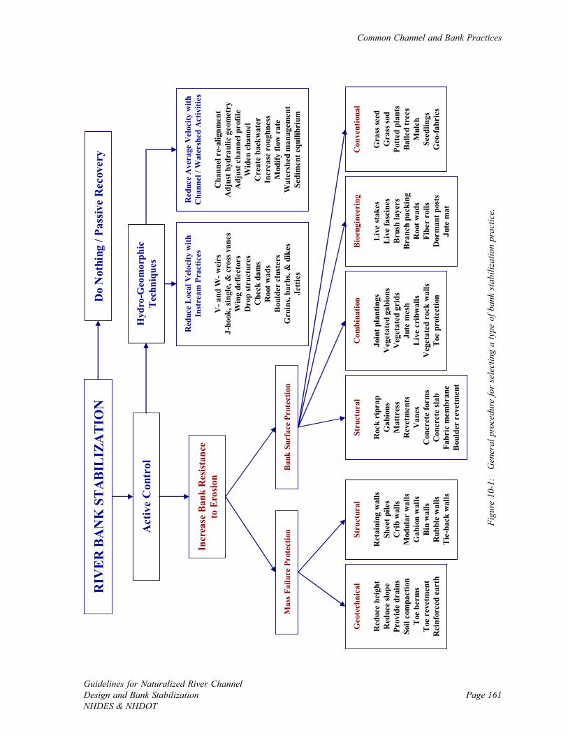
Common Channel and Bank Practices
Guidelines for Naturalized River ChannelDesign and Bank StabilizationNHDES & NHDOT
Page 161
RIV
ER
BA
NK
ST
AB
ILIZ
AT
ION
Act
ive
Con
trol
Hyd
ro-G
eom
orph
icTe
chni
ques
Red
uce
Ave
rage
Vel
ocity
with
C
hann
el /
Wat
ersh
ed A
ctiv
ities
Cha
nnel
re-
alig
nmen
tA
djus
t hyd
raul
ic g
eom
etry
Adj
ust c
hann
el p
rofil
eW
iden
cha
nnel
Cre
ate
back
wat
erIn
crea
se r
ough
ness
Mod
ify fl
ow r
ate
Wat
ersh
ed m
anag
emen
tSe
dim
ent e
quili
briu
m
Incr
ease
Ban
k R
esist
ance
to
Ero
sion
Do
Not
hing
/ Pa
ssiv
e R
ecov
ery
Geo
tech
nica
l
Red
uce
heig
htR
educ
e sl
ope
Prov
ide
drai
nsSo
il co
mpa
ctio
nT
oe b
erm
sT
oe r
evet
men
tR
einf
orce
d ea
rth
Stru
ctur
al
Ret
aini
ng w
alls
Shee
t pile
sC
rib
wal
lsM
odul
ar w
alls
Gab
ion
wal
lsB
in w
alls
Rub
ble
wal
lsT
ie-b
ack
wal
ls
Mas
s Fai
lure
Pro
tect
ion
Ban
k Su
rfac
e Pr
otec
tion
Stru
ctur
al
Roc
k ri
prap
Gab
ions
Mat
tres
sR
evet
men
tsV
anes
Con
cret
e fo
rms
Con
cret
e sl
abFa
bric
mem
bran
eB
ould
er r
evet
men
t
Com
bina
tion
Join
t pla
ntin
gsV
eget
ated
gab
ions
Veg
etat
ed g
rids
Jute
mes
hL
ive
crib
wal
lsV
eget
ated
roc
k w
alls
Toe
pro
tect
ion
Bio
engi
neer
ing
Liv
e st
akes
Liv
e fa
scin
esB
rush
laye
rsB
ranc
h pa
ckin
gR
oot w
ads
Fibe
r ro
llsD
orm
ant p
osts
Jute
mat
Con
vent
iona
l
Gra
ss se
edG
rass
sod
Pott
ed p
lant
sB
alle
d tr
ees
Mul
chSe
edlin
gsG
eo-f
abri
cs
Red
uce
Loc
al V
eloc
ity w
ith
Inst
ream
Pra
ctic
es
V-a
nd W
-wei
rsJ-
hook
, sin
gle,
& c
ross
van
esW
ing
defle
ctor
sD
rop
stru
ctur
esC
heck
dam
sR
oot w
ads
Bou
lder
clu
ster
sG
roin
s, ba
rbs,
& d
ikes
Jetti
es
Figu
re 1
0-1:
G
ener
al p
roce
dure
for
sele
ctin
g a
type
of b
ank
stab
iliza
tion
prac
tice.
Chapter 10.0
Guidelines for Naturalized River ChannelDesign and Bank Stabilization
NHDES & NHDOTPage 162
preferable (GASWCC, 2000), with a 1:1 maximum bank slope particularly for more erodable
soils. The bank angle is a function of the particle sizes and their cohesiveness (see Table 8-4).
General design considerations for bank stabilization projects have been laid out in existing
manuals (LCSMC, 2002), and, as with grade control, each site is unique and thus selected
practices are based on individual site conditions, constraints, and project objectives.
10.3.2 Soft (Bioengineering) Bank Stabilization Practices
River bank stabilization using natural vegetative materials such as coconut fiber rolls and live
staking are desired for their habitat benefits over harder practices such as riprap (Fischenich,
2003). Habitat benefits of bioengineering that are not present with riprap include
rehabilitation of bank and riparian vegetation, promotion of important habitat features such as
undercut banks and low overhanging vegetation, and importation of detritus and large woody
debris into the river channel (Schmetterling et al., 2001). The use of bioengineering practices
for bank stabilization has become widespread. Several existing manuals (e.g., Eubanks and
Meadows, 2002; LCSMC, 2002) solely address these natural material-based techniques, and
manuals exist to guide re-vegetation techniques as well (e.g., Walter et al., 2005).
Lower material stability thresholds (see Table 9-2) (Fischenich, 2001), fragile post-
construction periods until vegetation is established, and reduced life span in rivers prone to
scour, are central challenges associated with bioengineering applications. Although
bioengineering practices are preferable, lower stability thresholds often preclude application
on the submerged low bank, and at times even the mid bank. The range and duration of
submergence levels are important design considerations for bank stabilization projects when
working on large rivers or water bodies with fluctuating flow levels. Cabling materials in
place is possible, but a less desirable option that can result in dislocation of materials during
large floods and leaving metal wires, rebar, and baskets in the river channel (see Flosi et al.,
2002 for application notes). For high energy systems such as those with steep or moderate
slopes that are channelized, mostly disconnected from their floodplains, or in active
Common Channel and Bank Practices
Guidelines for Naturalized River ChannelDesign and Bank StabilizationNHDES & NHDOT
Page 163
adjustment where natural materials would be dislodged from the lower bank, combination
practices (e.g., Cramer et al., 2003) are recommended where the low bank is reinforced with a
hard material while the middle and upper bank are stabilized using bioengineering practices.
These combined approaches allow structural fixes that are more likely to achieve local channel
stability, and include some of the habitat benefits of bioengineering techniques.
Due to the reliance on established vegetation to stabilize river banks, bioengineering
applications are vulnerable to failure immediately following construction should a drought or
large flood take place. For large scale bioengineering applications, resources should be set
aside to water young plantings and to replace materials that die or are dislodged during flood
events. Vegetated geogrids and jute mats (Eubanks and Meadows, 2002) help increase the
durability of bioengineering projects immediately after installation. In addition, continued
maintenance is needed to remove weeds of and deter competing plants until the plantings are
large enough to survive. In addition, plantings must be protected from animal damage.
Saplings should have metal or thick plastic guards on their base to ward off beaver, and
herbaceous plantings may need to be fenced to keep deer, skunk, and other animals away.
The life span on bioengineering materials is typically much shorter than practices made from
rock, unless full re-vegetation is accomplished before the bank can fail again. This implies
that some level of passive recovery is expected once a bioengineering application is installed.
Passive recovery can include the growth of roots in the bank, the capture and re-vegetation of
fine sediments, and the migration of flow paths toward the center of the channel. In other
words, bioengineering approaches function best when the primary stressor has been removed
from the system and an assisted natural recovery is desired. Bioengineering approaches often
fail when applied on a very small scale to patch the channel response to a remaining problem.
In this case, funds are likely better spent to address the ultimate source of the problem.
Chapter 10.0
Guidelines for Naturalized River ChannelDesign and Bank Stabilization
NHDES & NHDOTPage 164
10.3.3 Hard (Traditional) Bank Stabilization Practices
Traditional bank stabilization practices primarily composed of rock have been used extensively
to manage rivers typically following floods and large erosion events, and in the vicinity of
infrastructure. Riprap, angular rock, is the most common traditional practice used to stabilize
a bank and limit lateral channel movement. Applications of riprap for bank stabilization
typically include laying down a filter layer to contain the bank material and then placing the
appropriate size stone on top for stabilization. Existing manuals and papers (e.g., NRCS,
1996; Fischenich, 2001, 2003) offer guidance on appropriate stone size for site conditions
(see Table 9-2). Grading is often performed prior to riprap applications to reduce the angle of
the bank relative to the water surface. Revetments made of shapes such as blocks and jacks
that are cast from concrete function in the same way as riprap to increase the resistance to
erosion on the river bank.
Riprap is well-known for both its utility where quick application is needed to stabilize a bank,
and for impairing aquatic habitat once installed. There are several ways to improve the poor
habitat value of a riprap application (Fischenich, 2003):
• Apply rock cautiously to maintain as many mature trees and shrubs as possible;
• Install joint plantings throughout the crevices of the riprap;
• Use few large boulders on the low bank to increase the size of interstitial spaces useful
for fish cover;
• Add structure to the installation such as spur dikes (perpendicular to flow) and ridges
(or groins) on the riprap; and
• Where appropriate, filling interstitial spaces with gravel to create salmonid spawning
habitat.
Gabions, or rock filled baskets, are also used to increase bank strength where either a short
section of bank is in need of stabilization or a stackable structural practice is desired.
Important application details are similar to riprap, with the added concern of the longevity of
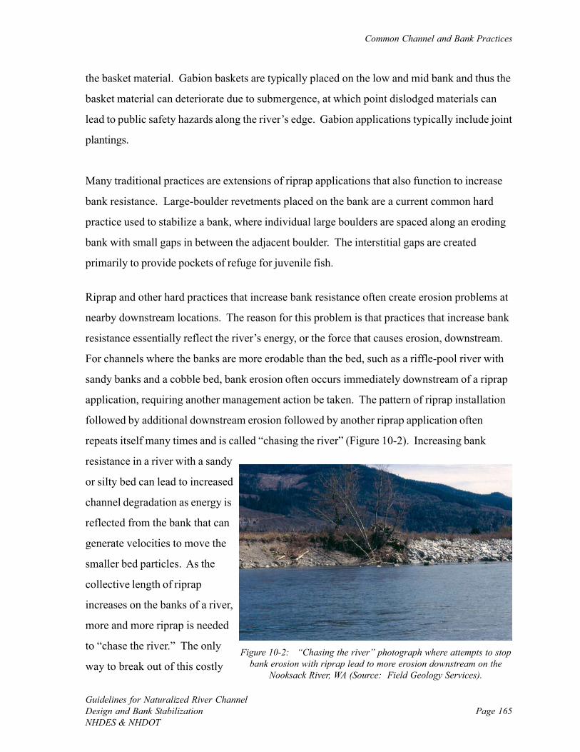
Common Channel and Bank Practices
Guidelines for Naturalized River ChannelDesign and Bank StabilizationNHDES & NHDOT
Page 165
Figure 10-2: “Chasing the river” photograph where attempts to stopbank erosion with riprap lead to more erosion downstream on the
Nooksack River, WA (Source: Field Geology Services).
the basket material. Gabion baskets are typically placed on the low and mid bank and thus the
basket material can deteriorate due to submergence, at which point dislodged materials can
lead to public safety hazards along the river’s edge. Gabion applications typically include joint
plantings.
Many traditional practices are extensions of riprap applications that also function to increase
bank resistance. Large-boulder revetments placed on the bank are a current common hard
practice used to stabilize a bank, where individual large boulders are spaced along an eroding
bank with small gaps in between the adjacent boulder. The interstitial gaps are created
primarily to provide pockets of refuge for juvenile fish.
Riprap and other hard practices that increase bank resistance often create erosion problems at
nearby downstream locations. The reason for this problem is that practices that increase bank
resistance essentially reflect the river’s energy, or the force that causes erosion, downstream.
For channels where the banks are more erodable than the bed, such as a riffle-pool river with
sandy banks and a cobble bed, bank erosion often occurs immediately downstream of a riprap
application, requiring another management action be taken. The pattern of riprap installation
followed by additional downstream erosion followed by another riprap application often
repeats itself many times and is called “chasing the river” (Figure 10-2). Increasing bank
resistance in a river with a sandy
or silty bed can lead to increased
channel degradation as energy is
reflected from the bank that can
generate velocities to move the
smaller bed particles. As the
collective length of riprap
increases on the banks of a river,
more and more riprap is needed
to “chase the river.” The only
way to break out of this costly
Chapter 10.0
Guidelines for Naturalized River ChannelDesign and Bank Stabilization
NHDES & NHDOTPage 166
management cycle is to begin to address the source of the problem and to take corrective
actions to reduce the rivers energy such as re-connect floodplains and eliminating conflicts by
giving the river the room to move.
Single rock vanes, J-hook vanes, and wing deflectors are practices that are typically used to
deflect flow away from an eroding bank, create downstream scour holes for refuge, and
diversify local hydraulics. Important application details include the rock size, proper elevation
to set the structures (bankfull at the bank and at the channel invert 1/4 to 1/3 of the way
across bankfull channel), angle relative to flow (20-30 degrees), and structure shape. A J-
hook locates the scour pool towards the middle of the channel cross section while the scour
pool associated with a single rock vane is closer to the bank.
Various types of wall/piling systems and slotted board fencing can be used to prevent lateral
channel migration where space is limited for a sloping bank. These practices essentially
eliminate the river bank and the connection between river and floodplain, and are only sug-
gested as a last option when the source of the problem cannot be fixed and unavoidable
conflicts must be resolved. An example of where a piling system may be recommended is
when very tall (i.e., ~100 ft) sandy banks of large rivers erode and threaten nearby infrastruc-
ture that cannot be moved. It is difficult to re-direct the flow of a large river during flood
events, so the project must primarily relay on increasing the resistance of the bank to erosion.
Large slumping sandy banks lack stable surfaces to anchor materials or install plantings so
pilings and walls can be used to create terraces on the low to mid bank, and then some
plantings can be attempted on the mid to upper bank.
An important application consideration for all practices where large rock is being used is the
ability of the river bed and banks to support heavy materials. If the potential exists for
underlying silt and clay, such as those associated with post-glacial lacustrine deposits, some
geotechnical testing may be required to confirm materials will not sink into the river bed. It is
always preferable to construct projects from the river bank to avoid the many negative
impacts of having construction equipment in the channel. If the only option is to construct a
Common Channel and Bank Practices
Guidelines for Naturalized River ChannelDesign and Bank StabilizationNHDES & NHDOT
Page 167
project from within the channel, geotechnical testing will also confirm if construction vehicles
can safely enter the river channel.
10.4 Habitat Elements
10.4.1 Introduction
Localized habitat enhancement uses practices to expand existing aquatic habitat features that
are deficient in the river channel. Habitat enhancement is most frequently used for improving
fisheries. Installation of habitat features alone typically does not address the source of a
problem, yet improves the current state of the rive channel as it responds to stressors. The
introduction of habitat features is common in small and medium rivers, and existing manuals
(e.g., Saldi-Caromile et al., 2004) can be used to guide feature selection and application.
10.4.2 Habitat Enhancement Practices
Large woody debris and debris jams are important habitat features that provide shelter and a
food source for some aquatic organisms. In addition, coarse woody material is important to
channel and bank stability. In small rivers, large trees can create step-pool networks that
control grade and stabilize banks via adding roughness to the channel boundaries. Trees and
jams contribute to grade control and bank stabilization in larger rivers as well. Installation of
large woody debris and jams is useful when natural woody riparian vegetation is limited. The
main challenge with the installation of large wood is preventing it from washing away during
moderate and high flows. Materials are typically tied into the banks and/or cabled into the bed
or banks. Keep in mind that the processing and downstream transfer of large wood is natural
in a river channel, although not desired if there is a lack of wood input.
Individual and clusters of instream boulders are typical habitat features in many river channel
types. The large rocks diversify local hydraulics and create holding locations for fish and
Chapter 10.0
Guidelines for Naturalized River ChannelDesign and Bank Stabilization
NHDES & NHDOTPage 168
insects. Large material, diameter of 2 to 5 feet (MDE, 2000), is recommended for boulder
applications. Instream boulders are typically applied in conjunction with other practices.
Other features that can be installed to enhance local habitat include lunker structures to mimic
undercut banks, clean gravels for spawning, and side- and off-channel for refuge areas.
As with all other types of practices, installed habitat elements should be consistent with
naturally occurring habitats in healthy portions of the project river, or healthy reference sites
in nearby rivers in the watershed.
10.5 Vegetated Riparian Buffers
A wide naturally vegetated and undisturbed riparian buffer improves bank and channel
stability, protects water quality, and supports a healthy aquatic ecosystems. Buffer protection
and re-vegetation are typical components of moderate and comprehensive naturalized river
channel design and bank stabilization projects. Riparian practices can be difficult to apply as
river corridors often contain human infrastructure such as roadways, utilities, and structures.
Inclusion of buffer practices to improve the amount and type of vegetation in conjunction with
bank and channel work increases the chances of a successful project. The protection and re-
introduction of buffer vegetation is an important practice to consider with every project or
management activity.
Naturally vegetated buffers and extended floodplains reduce peak river flows by absorbing
and slowing portions of incident stormwater runoff that must travel through hydraulically
rough areas on the way to a river channel. The long, slow flow path common in vegetated
buffers also allows for sediment, nutrient, and pollutant removal to safeguard water quality
(Perry et al., 1999; Dabney et al., 2006). Bank stability generally increases with riparian
vegetation due to hydrologic (i.e., interception and evapotranspiration) and mechanical (i.e.,
soil compression increases with root tensile strength) effects (Simon and Collison, 2002). A
lack of a buffer can lead to bank erosion and even channel degradation. If excessive down-
Common Channel and Bank Practices
Guidelines for Naturalized River ChannelDesign and Bank StabilizationNHDES & NHDOT
Page 169
cutting takes place, the channel can no longer access its floodplain. At this point, all of the
energy associated with runoff events is confined to the river channel, channel adjustment often
intensifies, and the threat to human investments dramatically increases.
Naturally vegetated and undisturbed riparian buffers are important for aquatic habitat.
Beyond the reduction of flood flows and the protection of water quality, buffers help maintain
physical habitat (Wang et al., 1997; Sweeney et al., 2004). Large woody debris and coarse
particulate organic matter are essential for many different aquatic organisms and are
introduced to the channel from the buffer. In fact, large trees that fall into small, steep
headwater channels are critical for setting up the step-pool patterns often present in this
location. Direct associations have been shown between shredding macroinvertebrates and the
riparian plant communities growing in their immediate upstream surroundings (Cummins et
al., 1989). Fish also depend on vegetated buffers for cover, with the overhanging vegetation
near the water surface and the overhead tree canopy providing shelter. Some of the insects
that salmonids consume either live in or use buffer vegetation for part of their life cycle.
Buffers thus also play an important role in the aquatic food chain in rivers.

Chapter 10.0
Guidelines for Naturalized River ChannelDesign and Bank Stabilization
NHDES & NHDOTPage 170
[Page intentionally left blank.]
Page 171Guidelines for Naturalized River ChannelDesign and Bank StabilizationNHDES & NHDOT
CHAPTER 11.0: IMPLEMENTATION
11.1 Introduction
The implementation process for naturalized channel design and bank stabilization varies for
routine, moderate, and comprehensive projects. Implementation includes funding, regulatory
permitting, and land rights, which are all essential for moving a project beyond design towards
construction. These time-consuming tasks must be initiated at the very beginning of project
planning to improve the chances of implementation as scheduled by the project team.
11.2 Regulatory Permits and Reviews
11.2.1 Introduction
Several state and federal agencies regulate activities that affect water resources in New
Hampshire (Figure 11-1). The series of regulatory programs that expanded since the 1970s is
intended to protect water resources including river channels, banks, wetlands, tidal waters,
and adjacent lands. Permits specifically have thresholds of applicability that attempt to protect
water quality, minimize erosion and sediment deposition, conserve fish and wildlife habitat,
minimize flooding, protect endangered species, protect potable water supplies, and maintain
instream flows.
The specific activities that are regulated vary from one agency to another, as does the
permitting threshold that determines if an activity is either exempt or requires a permit.
Regulated activities in rivers or wetlands include discharges, excavation, construction of
culverts, bridges, dams or dikes, bank disturbance, dredging, and filling. Some activities on
lands adjacent to surface waters are also regulated, such as earth moving, applying fertilizer,
cutting vegetation, wells, and septic systems.
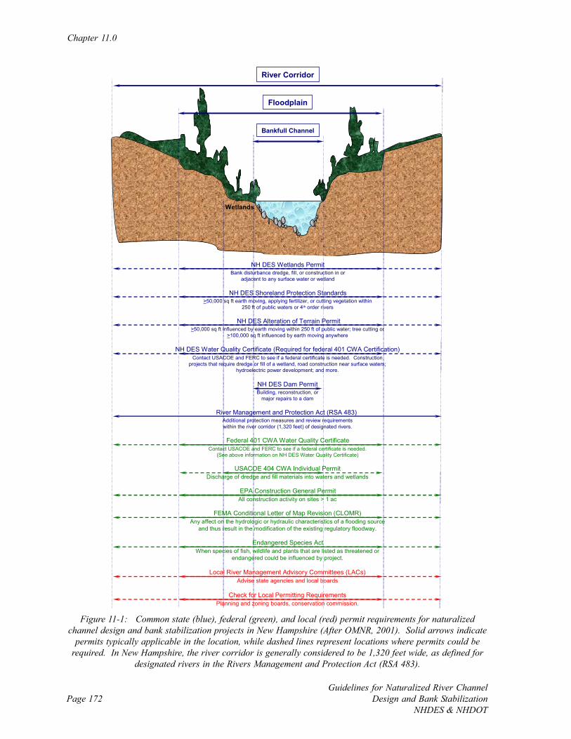
Chapter 11.0
Guidelines for Naturalized River ChannelDesign and Bank Stabilization
NHDES & NHDOTPage 172
Figure 11-1: Common state (blue), federal (green), and local (red) permit requirements for naturalizedchannel design and bank stabilization projects in New Hampshire (After OMNR, 2001). Solid arrows indicate
permits typically applicable in the location, while dashed lines represent locations where permits could berequired. In New Hampshire, the river corridor is generally considered to be 1,320 feet wide, as defined for
designated rivers in the Rivers Management and Protection Act (RSA 483).
Bankfull Channel
River Corridor
Floodplain
Wetlands
>50,000 sq ft influenced by earth moving within 250 ft of public water; tree cutting or >100,000 sq ft influenced by earth moving anywhere
NH DES Water Quality Certificate (Required for federal 401 CWA Certification)Contact USACOE and FERC to see if a federal certificate is needed. Construction
projects that require dredge or fill of a wetland, road construction near surface waters; hydroelectric power development; and more.
Discharge of dredge and fill materials into waters and wetlands
Contact USACOE and FERC to see if a federal certificate is needed.(See above information on NH DES Water Quality Certificate)
All construction activity on sites > 1 ac
Any affect on the hydrologic or hydraulic characteristics of a flooding source and thus result in the modification of the existing regulatory floodway.
When species of fish, wildlife and plants that are listed as threatened or endangered could be influenced by project.
Advise state agencies and local boards
NH DES Wetlands PermitBank disturbance dredge, fill, or construction in or
adjacent to any surface water or wetland
NH DES Shoreland Protection Standards>50,000 sq ft earth moving, applying fertilizer, or cutting vegetation within
250 ft of public waters or 4th order rivers
NH DES Alteration of Terrain Permit
NH DES Dam PermitBuilding, reconstruction, or
major repairs to a dam
Federal 401 CWA Water Quality Certificate
USACOE 404 CWA Individual Permit
EPA Construction General Permit
FEMA Conditional Letter of Map Revision (CLOMR)
Endangered Species Act
Local River Management Advisory Committees (LACs)
Planning and zoning boards, conservation commission. Check for Local Permitting Requirements
River Management and Protection Act (RSA 483) Additional protection measures and review requirements within the river corridor (1,320 feet) of designated rivers.
Implementation
Guidelines for Naturalized River ChannelDesign and Bank StabilizationNHDES & NHDOT
Page 173
The process of preparing, submitting, and processing regulatory permits can be very time
consuming and expensive. It is a complex task because of overlapping jurisdictions, detailed
application requirements, and limited agency staff to assist with the procedure. Although the
regulatory process can be complicated, New Hampshire Department of Environmental
Services (DES) staff is available to assist with the planning and permitting of complex
naturalized channel design and bank river stabilization projects. Technical staff is actively
involved in project planning around the state and participate in many professional committees
and task force groups to stay current on natural channel design and bio-engineered bank
stabilization techniques. Pre-application meetings with DES staff are welcomed and strongly
encouraged. The general permitting process includes the following steps:
• Identify project goals and objectives;
• Identify proposed activities;
• Gather data, map wetlands;
• Evaluate alternatives;
• Define potential regulatory permits;
• Identify regulated activities;
• Conduct pre-application meeting;
• Assess methods to avoid regulated activities;
• Minimize resource impacts;
• Develop mitigation plan for unavoidable impacts;
• Prepare permit application package;
• Respond to review comments;
• Public notice;
• Public hearing (if needed); and
• Decision.
Chapter 11.0
Guidelines for Naturalized River ChannelDesign and Bank Stabilization
NHDES & NHDOTPage 174
11.2.2 Pre-application Meetings
State and federal permits, and occasionally local permits, have specific criteria for regulatory
eligibility, exclusions, and application data. Regulations and their criteria periodically change
and need to be reviewed for each new project.
Applicants for proposed projects that affect New Hampshire wetlands, shorelands,
floodplains, and public waters are advised to schedule a pre-application meeting with
appropriate agencies. The purpose of this meeting is to explore current regulations, define the
project goals and activities, assess the project’s regulated activities, and confirm regulatory
permit data needs. The meeting should identify potential regulatory issues and adverse
impacts, alternatives that need to be evaluated, and mitigation. Many permitting data
requirements are regularly collected as part of the design.
11.2.3 Federal Permit Summary
Federal legislation has created numerous regulatory programs concerning water resources,
including “Waters of United States” that are required for projects in New Hampshire (see
Figure 11-1). The main programs are authorized by the Clean Water Act (CWA) (1972) and
subsequent US EPA (EPA) and US Army Corps of Engineers (USACOE) regulations. The
CWA delegates permitting to the USACOE.
The main programs are authorized by the Clean Water Act (CWA) of 1972 and subsequent US
Environmental Protection Agency (EPA) regulations, some of which delegate enforcement to
the US Army Corps of Engineers (USACOE). The key federal regulatory programs include:
• CWA (Section 404, USACOE);
• CWA (Section 401, Water Quality Certifications, DES);
• Rivers and Harbors Act of 1899 (Section 10);
• National Environmental Policy Act (NEPA);
Implementation
Guidelines for Naturalized River ChannelDesign and Bank StabilizationNHDES & NHDOT
Page 175
• Marine Protection, Research, and Sanctuaries Act (MPRSA) (Section 103);
• Endangered Species Act - US Fish and Wildlife Service (FWS), EPA, National Marine
Fisheries Service (NMFS) of the National Oceanic and Atmospheric Administration
(NOAA);
• National Historic Preservation Act (Section 106);
• Federal Energy Regulatory Commission (FERC) Licenses;
• Federal Emergency Management Agency (FEMA), National Flood Insurance
Program; and
• Wild and Scenic Rivers Act.
The Section 404 permit affects most projects and is a key to successful permitting. The
program is administered by the USACOE, in cooperation with EPA, NMFS, FWS, and state
agencies.
Three categories of regulated activities are defined by the New Hampshire Programmatic
General Permit (PGP).
Minimum: Activities of minimal environmental impact that do not require USACOE
regulatory review and are classified as non-reporting, yet projects must still comply with
conditions contained in the PGP. In New Hampshire, a project is called minimum and does
not require USACOE notification if less than 3,000 square feet of fill or dredge are taking
place.
Minor: Activities likely to be of minimal environmental impact but that have the potential to
have adverse effects. Project specific review and authorization from the USACOE in writing
is required. All activities involving dams, dikes, water withdrawals and diversions are
classified as minor. Minor projects apply to activities with more than 3,000 square feet of fill
or dredge that affect less than three acres.
Chapter 11.0
Guidelines for Naturalized River ChannelDesign and Bank Stabilization
NHDES & NHDOTPage 176
Major: Activities that have the potential to cause adverse environmental impacts or are too
big for the minor category require project-specific review, are available for public review and
comment, and may require preparation of an Environmental Impact Statement. Major permits
are required for projects over three acres or when requested by the USACOE.
Permits typically stipulate seasonal limits of when regulated activities are allowed; usually July
1 to September 30th. The USACOE may confer with other federal agencies, including FWS,
EPA, NOAA, NMFS, FERC, and the State Historic Preservation Officer.
11.2.4 New Hampshire Permits and Reviews
DES has several regulatory programs that apply to naturalized channel design and bank
stabilization projects (see Figure 11-1). The Guidebook for Environmental Permits in New
Hampshire is available on the Internet (http://www.des.state.nh.us/PermitGuide/) and contains
useful information to get started with project permitting. Contact DES for permitting
guidance on all projects.
New Hampshire permitting requirements for naturalized channel design and bank stabilization
projects include:
• DES Wetlands Permit;
• DES Shoreland Protection Standards;
• DES Alteration of Terrain Permit;
• DES Water Quality Certificate;
• DES Dam Permit; and
• New Hampshire Rivers Management and Protection Act (RSA 483).
Most naturalized channel design and bank stabilization projects require a state wetlands
permit because projects take place in or adjacent to any surface water or wetland. RSA 482-
A authorizes DES to protect the state’s wetlands and surface waters by requiring a permit for
Implementation
Guidelines for Naturalized River ChannelDesign and Bank StabilizationNHDES & NHDOT
Page 177
dredge or fill or construction of structures in wetlands or other waters of the state (http://
www.gencourt.state.nh.us/rsa/html/NHTOC/NHTOC-L-482-A). The permit generally applies
to any activities (e.g., bank stabilization, installation of structures in the channel, dredging, fill
placement, and culvert installation) that take place below the natural mean high water level of
any public waters. Useful information on wetland permitting can be found on the Internet site
of the DES Wetlands Bureau (http://www.des.state.nh.us/wetlands/).
The state Comprehensive Shoreland Protection Act (CSPA) (RSA 483-B) (http://
www.gencourt.state.nh.us/rsa/html/nhtoc/nhtoc-l-483-b) regulates activities in areas adjacent
to river channels and wetlands. The CSPA applies to all land within 250' of waters listed in
the Official List of Public Waters and fourth order and larger streams (except the Saco and
Pemigewasset Rivers). Projects and activities located in the protected shoreland are subject
to Minimum Shoreland Protection Standards as set forth in the CSPA. Regulated activities
include earth moving or excavation of areas over 50,000 square feet, cutting vegetation, and
certain building modifications. Useful information on the applicability of the minimum
shoreland standards to a project can be found on the Internet (http://www.des.state.nh.us/
cspa/).
An Alteration of Terrain (or Site Specific) Permit regulates construction, earth moving or
other substantial alteration of the characteristics of the terrain when a contiguous area of
100,000 square feet or more will be disturbed. The jurisdictional area of disturbance is
lowered to 50,000 square feet of earth moving when it is within 250 ft of public water, or the
state shoreland. The permit is issued by the DES Water Division under the Water Pollution
and Waste Disposal Act (RSA 485-A) (http://www.gencourt.state.nh.us/rsa/html/NHTOC/
NHTOC-L-485-a). Useful information on the Alteration of Terrain Permit can be found on
the Internet (http://www.des.state.nh.us/SiteSpecific/).
A Section 401 CWA Water Quality Certificate is needed from the state for any project where a
federal permit is being sought to conduct any activity that may result in a discharge of material
into navigable waters. The purpose of the state permit is to provide the federal permitting
Chapter 11.0
Guidelines for Naturalized River ChannelDesign and Bank Stabilization
NHDES & NHDOTPage 178
agency (i.e., USACOE and FERC) with a certification from the state agency where the
discharge originates (i.e., DES) that the discharge will meet state surface water quality
standards. The permit is issued by the DES Watershed Management Bureau under the Water
Pollution and Waste Disposal Act (RSA 485-A) (http://www.gencourt.state.nh.us/rsa/html/
NHTOC/NHTOC-L-485-a). Surface waters include, but are not limited to rivers, lakes,
ponds, and wetlands. Useful information on the Section 401 Water Quality Certificate can be
found on the Internet (http://www.des.state.nh.us/WMB/Section401/).
DES, through its Dam Bureau (http://www.des.state.nh.us/dam/), regulates the repair,
reconstruction, maintenance, and operation of existing dams, and reviews design plans and
issues decisions for the construction, operation, and maintenance of new dams. Any project
involving a jurisdictional dam is regulated under the Dams, Mills, and Flowage Act (RSA 482)
(http://www.gencourt.state.nh.us/rsa/html/NHTOC/NHTOC-L-482). Jurisdictional dams in
New Hampshire are defined as any artificial barrier, including appurtenant works, which
impounds or diverts water, and which has a height of 4 feet or more, or a storage capacity of
2 acre-feet or more, or is located at the outlet of a great pond. A roadway culvert shall not be
considered a dam if its invert is at the natural bed of the water course, it has adequate
discharge capacity, and it does not impound water under normal circumstances.
Though it is not an additional permit, designated rivers under the New Hampshire Rivers
Management and Protection Act (RSA 483) require additional review and have some
additional protection measures (http://www.gencourt.state.nh.us/rsa/html/NHTOC/NHTOC-
L-483). A designated river is one that is “managed and protected for its outstanding natural
and cultural resources (http://www.des.state.nh.us/rivers/desigriv/)” (Appendix G). Reviews
are required for activities in the river corridor, which RSA 483 defines as “the land area
located within a distance of 1,320 feet of the normal high water mark or to the landward
extent of the 100 year floodplain as designated by the Federal Emergency Management
Agency, whichever distance is larger.” Useful information on RSA 483 can be found at the
DES RMPP Internet site (http://www.des.state.nh.us/rivers).

Implementation
Guidelines for Naturalized River ChannelDesign and Bank StabilizationNHDES & NHDOT
Page 179
RSA 483 also established local river management advisory committees (LACs), which are
citizens appointed to help create river corridor management plans for designated rivers. LACs
also participate in other activities to protect and improve the resource, such as the review of
proposed projects on designated rivers. LACs report to state agencies and local boards.
Local conservation commissions and planning and zoning boards may also play a role in
permit review. Based on the reports from LACs and their own project review, a decision is
made on the level of support of the project. Local boards often request information on how
the project will influence the local resource and area both during implementation and once
complete.
11.3 Funding
11.3.1 Introduction
Financial assistance for naturalized channel design and bank stabilization projects is available
from many government and private sources (Table 11-1). Routine projects are often funded
by the affected property owner, particularly for bank stabilization and planting. Moderate
and comprehensive projects encompass a larger geographical area often involving multiple
land-owners, infrastructure elements, and reaches. As the level of complexity increases with
project design and implementation, there is a parallel rise in project cost.
The majority of funding sources are typically awarded to state agencies, non-profit
organizations, and municipalities. It is therefore advantageous for individual land-owners to
bring potential naturalized river channel design and bank stabilization projects to the attention
of local, regional, and state resource organizations and agencies when financial limitations are
anticipated. The partnerships formed with local watershed associations, state agencies,
municipalities, and other non-profit organizations generate diversified funding options, access
to technical support, and eligibility to receive grant funding from various sources. In addition
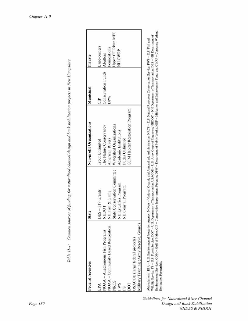
Chapter 11.0
Guidelines for Naturalized River ChannelDesign and Bank Stabilization
NHDES & NHDOTPage 180
Fede
ral A
genc
ies
Stat
eN
on-p
rofit
Org
aniz
atio
nsM
unic
ipal
Priv
ate
EPA
DES
– 3
19 G
rant
sTr
out U
nlim
ited
CIP
Land
-ow
ners
NO
AA
– A
nadr
omou
s Fis
h Pr
ogra
ms
NH
DO
TTh
e N
atur
e C
onse
rvan
cyC
onse
rvat
ion
Fund
sA
butte
rsN
OA
A –
Com
mun
ity B
ased
Res
tora
tion
NH
Fis
h &
Gam
eA
mer
ican
Riv
ers
DPW
Foun
datio
nsN
RCS
Stat
e C
onse
rvat
ion
Com
mitt
eeW
ater
shed
Org
aniz
atio
nsU
pper
CT
Rive
r MEF
FWS
NH
Est
uarie
s Pro
gram
Aca
dem
ic In
stitu
tions
NH
CW
RPFS
NH
Coa
stal
Pro
gram
Duc
ks U
nlim
ited
DO
TG
OM
Hab
itat R
esto
ratio
n Pr
o gra
mU
SAC
OE
(larg
e fe
dera
l pro
ject
s)M
ilita
ry T
rain
ing
(Arm
y Re
serv
e, G
uard
)
Abb
revi
atio
ns:
EPA
= U
.S. E
nviro
nmen
tal P
rote
ctio
n A
genc
y; N
OA
A =
Nat
iona
l Oce
anic
and
Atm
osph
eric
Adm
inist
ratio
n; N
RC
S =
U.S
. Nat
ural
Res
ourc
es C
onse
rvat
ion
Serv
ice;
FW
S =
U.S
. Fish
and
W
ildlif
e Se
rvic
e; F
S =
U.S
. For
est S
ervi
ce; D
OT
= U
.S. D
epar
tmen
t of T
rans
porta
tion;
USA
CO
E =
U.S
. Arm
y C
orps
of E
ngin
eers
; NH
DO
T =
NH
Dep
artm
ent o
f Tra
nspo
rtatio
n; D
ES =
NH
Dep
artm
ent o
f En
viro
nmen
tal S
ervi
ces;
GO
M =
Gul
f of M
aine
; CIP
= C
onse
rvat
ion
Impr
ovem
ent P
rogr
am; D
PW =
Dep
artm
ent o
f Pub
lic W
orks
; MEF
= M
itiga
tion
and
Enha
ncem
ent F
und;
and
CW
RP
= C
orpo
rate
Wet
land
R
esto
ratio
n Pa
rtner
ship
.Tabl
e 11
-1:
Com
mon
sou
rces
of f
undi
ng fo
r na
tura
lized
cha
nnel
des
ign
and
bank
sta
biliz
atio
n pr
ojec
ts in
New
Ham
pshi
re.
Implementation
Guidelines for Naturalized River ChannelDesign and Bank StabilizationNHDES & NHDOT
Page 181
to the funding options that the partnerships create, the project goals can often fulfill elements
within watershed management plans, corridor management plans, and other resource based
conservation or restoration efforts thereby leveraging matching funds and project management
support that would normally be unavailable to the individual land owner.
11.3.2 Fund Raising
Raising ample funds for moderate and comprehensive projects that require multiple funding
sources and matching requirements can be a daunting task for the individual land-owner
seeking to implement naturalized river channel design and bank stabilization. Forging
partnerships with local watershed organizations, non-profit organizations, municipalities, and
state agencies will provide the local support, technical assistance, and guidance required for
securing the appropriate funding sources available for project implementation.
Funding applications require a clear connection between the project goals and those of the
funding institutions. Financial grants are often conditional upon raising matching funds, and
some project elements such as utilities and land rights may not be eligible for grants. The
funding sources listed above (see Table 11-1) have varying grant cycles and requirements for
applicants to fulfill. It is highly advisable to speak with representatives from potential funding
sources prior to submitting a grant application to ensure project eligibility and to request
guidance with the grant application process.
Competitive grant programs typically develop contracts and/or grant agreements between the
grant provider and the project implementer. A project schedule is developed based upon tasks
and deliverables with measures of environmental success integrated throughout the
implementation phases of the project. Projects receiving funding must have a high probability
of leading to successfully completed projects that meet the conservation or restoration goals
established by the grant provider and the project implementer.
Chapter 11.0
Guidelines for Naturalized River ChannelDesign and Bank Stabilization
NHDES & NHDOTPage 182
Grant applications generally require a preliminary study to define the project problem, goals,
alternatives, and feasibility of implementation options. This initial document needs to identify
project issues, project benefits, and potential adverse impacts. This information is readily
available following project classification as routine, moderate or comprehensive, and
following the initial assessment. Project cost estimates are required as part of the final grant
application process. Receipt of financial grants requires that an efficient accounting system be
in place, which is another reason for developing partnerships with watershed organizations,
municipalities, and other non-profit organizations that routinely manage budgets and process
invoices. Additional responsibilities that can be required as a grant recipient include
competitive contractor selection via bids, preparation of environmental permits, and post-
construction performance monitoring.
Construction projects can be expensive and involve unanticipated conditions, design changes,
and weather-related delays and costs such as floods. Experienced project budget development
and careful financial management is necessary to track expenses, matching sources (in-kind
and cash), as well as maintaining a contingency or reserve fund whenever possible.
There are several naturalized channel design and bank stabilization projects in New Hampshire
that originated with individual land-owner concerns that eventually matured into multi-source
funded projects. The partnerships developed from these initial inquiries led to the acquisition
of funding, professional design, construction supervision, and ultimately the implementation of
successful projects that achieved self-sustaining stable channels that are preferred over the
typical patch fixes often undertaken by individual land-owners on their own.
11.4 Land Rights and Access
Naturalized channel design and bank stabilization projects may involve both private and public
properties, plus public waters of the state and navigable waters of United States. In all cases,
access must be granted to the project site from the land owner. Gaining legal access may
Implementation
Guidelines for Naturalized River ChannelDesign and Bank StabilizationNHDES & NHDOT
Page 183
include temporary permission to work on property, temporary construction easements,
permanent easements, and land acquisition. The right to inundate land may be required on
projects that raise water levels or divert water to areas that would not normally be inundated.
Naturalized channel design and bank stabilization projects that partially or fully drain
impoundments need to research and address water use rights. All property and water rights
need to be carefully documented, often requiring the services of a licensed land surveyor and a
lawyer that specializes in property rights.
For routine or smaller moderate projects land access may be confirmed with a simple letter
agreement that defines the area involved, allowable activities, project duration, completion
dates, and proposed site conditions. Photograph the site just prior to initiating work to
document the pre-project conditions for land-owners and abutters. For comprehensive
projects, it is advisable to have formally surveyed easement maps and legal documents
describing the terms of agreement for land access.
Access should include a route to reach the project site from a public road, storage areas for
materials and equipment, clearing rights, grading rights, sanitary facilities, and electrical
power lines as needed. Long-term considerations include project site ownership, public
access after implementation, signage, fences, and maintenance.
11.5 Construction Phase
11.5.1 Introduction
Most naturalized channel design and bank stabilization projects require some kind of
construction work along the bed, banks, or shoreline area of a watercourse or wetland. Even
small construction projects can be surprisingly difficult when working with water in
environmentally sensitive areas often prone to flooding and with complicated access.
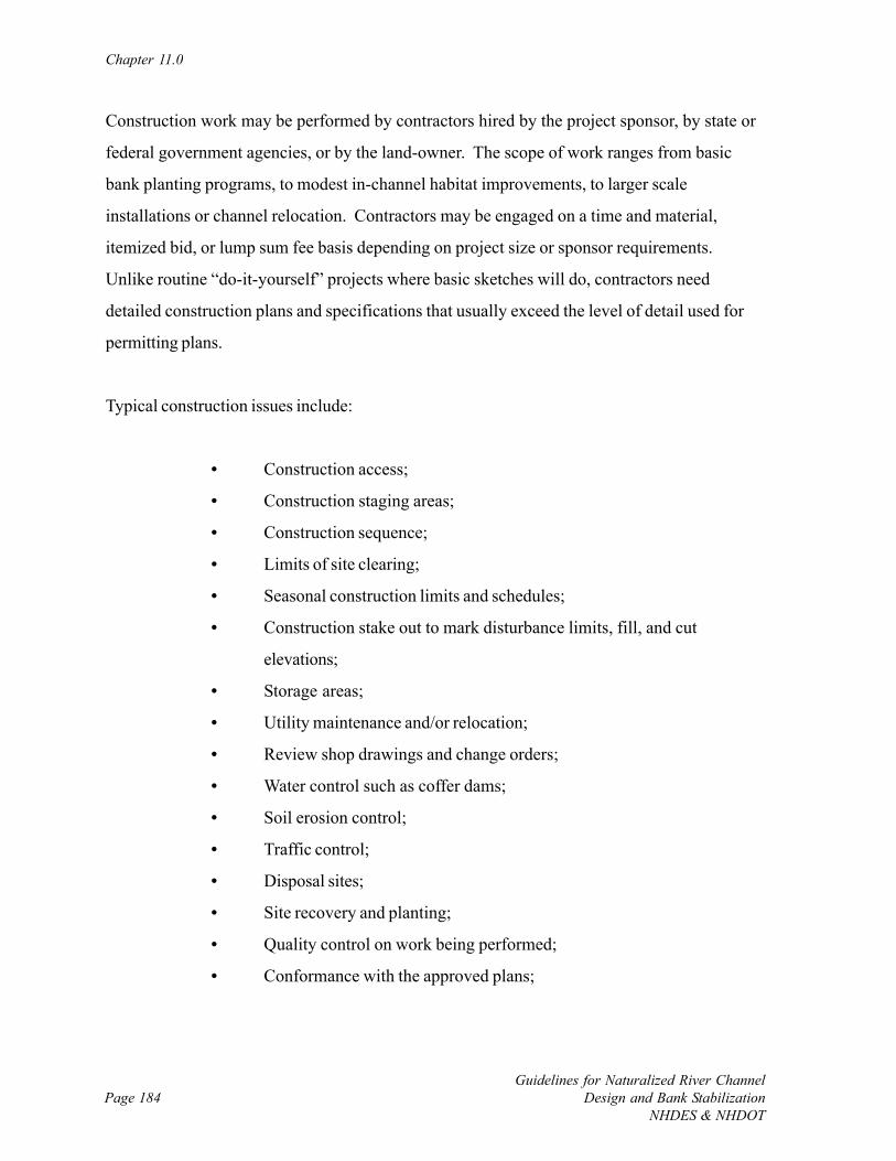
Chapter 11.0
Guidelines for Naturalized River ChannelDesign and Bank Stabilization
NHDES & NHDOTPage 184
Construction work may be performed by contractors hired by the project sponsor, by state or
federal government agencies, or by the land-owner. The scope of work ranges from basic
bank planting programs, to modest in-channel habitat improvements, to larger scale
installations or channel relocation. Contractors may be engaged on a time and material,
itemized bid, or lump sum fee basis depending on project size or sponsor requirements.
Unlike routine “do-it-yourself” projects where basic sketches will do, contractors need
detailed construction plans and specifications that usually exceed the level of detail used for
permitting plans.
Typical construction issues include:
• Construction access;
• Construction staging areas;
• Construction sequence;
• Limits of site clearing;
• Seasonal construction limits and schedules;
• Construction stake out to mark disturbance limits, fill, and cut
elevations;
• Storage areas;
• Utility maintenance and/or relocation;
• Review shop drawings and change orders;
• Water control such as coffer dams;
• Soil erosion control;
• Traffic control;
• Disposal sites;
• Site recovery and planting;
• Quality control on work being performed;
• Conformance with the approved plans;
Implementation
Guidelines for Naturalized River ChannelDesign and Bank StabilizationNHDES & NHDOT
Page 185
• Conformance with the regulatory permits;
• Measurement of work and payment; and
• Progress reports.
11.5.2 Construction Administration
Construction administration tasks are related to engaging a contractor and serving as a
coordinator between the contractor and project sponsor. Typical construction administration
tasks include:
• Advertise for bids;
• Respond to bidder’s questions;
• Pre-bid meetings;
• Review contractor bids;
• Review contractor qualifications;
• Help select successful bidder;
• Pre-construction meetings;
• Clarification of contract drawings;
• Review contractor submissions;
• Payment reviews;
• Review shop drawings, materials;
• As-built drawings;
• Progress meetings and reports; and
• Final punch list of outstanding work.
The construction administrator works in careful coordination with the on-site inspector for
comprehensive projects, and may perform both functions for routine and moderate projects.
Chapter 11.0
Guidelines for Naturalized River ChannelDesign and Bank Stabilization
NHDES & NHDOTPage 186
11.5.3 Construction Inspection
Construction work on naturalized channel design and bank stabilization projects should be
inspected by an experienced person familiar with the design intent, goals, and contract
documents. The inspector provides on-site guidance and quality control but does not
guarantee contractor performance. The common tasks of the construction inspector include:
• Observe construction work;
• Record deviations from plans and specifications;
• Inspects materials;
• Records quantities of items and work performed;
• Prepares progress reports;
• Conduct final inspection and report on findings; and
• Consults with construction administrator.
Page 187Guidelines for Naturalized River ChannelDesign and Bank StabilizationNHDES & NHDOT
CHAPTER 12.0: EVALUATION AND MANAGEMENT
12.1 Introduction
A project is not complete until some level of post-implementation evaluation is performed to
determine the effectiveness, and if specific objectives and over-arching goals have been
achieved. Evaluation also indicates if regularly scheduled operation and maintenance is
sufficient. If the project is not performing as anticipated adaptive management, or adjustment
of the project installation, may be needed.
The amount of recommended evaluation is a function of whether a project is routine,
moderate or comprehensive, where monitoring needs are typically larger for more involved
projects with biological and water quality improvement goals (Figure 12-1). Evaluation
generally includes the assessment of physical channel (stability), biomonitoring, and
measurement of basic and priority chemical parameters. Monitoring requirements can also be
linked to permitting, especially for long-term monitoring for more complex projects, so the
recommendations here must be considered along with required monitoring.
The minimal baseline assessment recommended for all projects includes:
1. Seasonal photo documentation for one year (see Appendix B), with record of extreme
flow events to understand any channel adjustment that takes place;
2. Estimate of the physical stability of the channel, banks, and installed practices; and
3. Qualitative report on project outcome.
A single rapid field assessment is also recommended for routine projects. For routine projects
with the main goal of increasing channel stability, measurements at monumented cross
sections with a tape measure and surveying the channel slope with a hand level are
recommended to see how the channel is moving locally. Routine projects with biological or
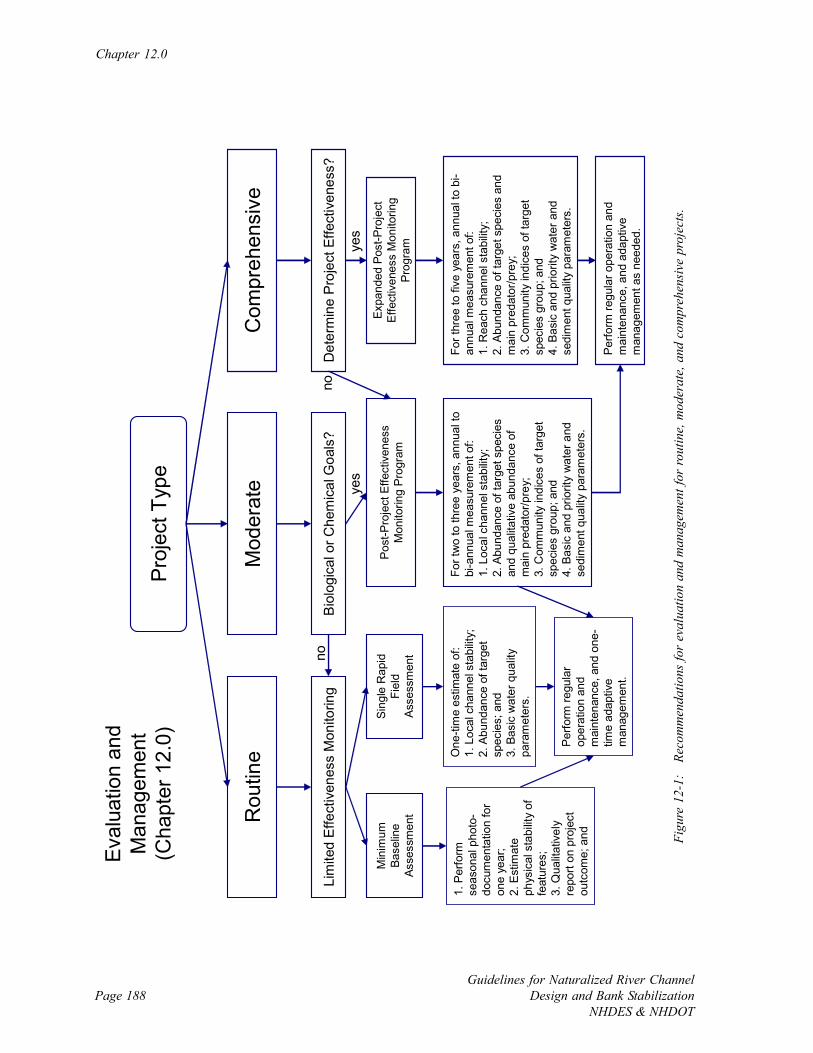
Chapter 12.0
Guidelines for Naturalized River ChannelDesign and Bank Stabilization
NHDES & NHDOTPage 188
Proj
ect T
ype
Mod
erat
eR
outin
eC
ompr
ehen
sive
Eval
uatio
n an
dM
anag
emen
t(C
hapt
er 1
2.0)
Min
imum
Ba
selin
e As
sess
men
t
Bio
logi
cal o
r Che
mic
al G
oals
?
Post
-Pro
ject
Effe
ctiv
enes
s M
onito
ring
Prog
ram
Det
erm
ine
Pro
ject
Effe
ctiv
enes
s?
Expa
nded
Pos
t-Pro
ject
Ef
fect
iven
ess
Mon
itorin
g Pr
ogra
m
For t
wo
to th
ree
year
s, a
nnua
l to
bi-a
nnua
l mea
sure
men
t of:
1. L
ocal
cha
nnel
sta
bilit
y;2.
Abu
ndan
ce o
f tar
get s
peci
es
and
qual
itativ
e ab
unda
nce
of
mai
n pr
edat
or/p
rey;
3. C
omm
unity
indi
ces
of ta
rget
sp
ecie
s gr
oup;
and
4. B
asic
and
prio
rity
wat
er a
nd
sedi
men
t qua
lity
para
met
ers.
For t
hree
to fi
ve y
ears
, ann
ual t
o bi
-an
nual
mea
sure
men
t of:
1. R
each
cha
nnel
sta
bilit
y;2.
Abu
ndan
ce o
f tar
get s
peci
es a
nd
mai
n pr
edat
or/p
rey;
3. C
omm
unity
indi
ces
of ta
rget
sp
ecie
s gr
oup;
and
4. B
asic
and
prio
rity
wat
er a
nd
sedi
men
t qua
lity
para
met
ers.
yes
no
Perfo
rm re
gula
r ope
ratio
n an
d m
aint
enan
ce, a
nd a
dapt
ive
man
agem
ent a
s ne
eded
.
Sing
le R
apid
Fi
eld
Asse
ssm
ent
yes
no
1. P
erfo
rm
seas
onal
pho
to-
docu
men
tatio
n fo
r on
e ye
ar;
2. E
stim
ate
phys
ical
sta
bilit
y of
fe
atur
es;
3. Q
ualit
ativ
ely
repo
rt on
pro
ject
ou
tcom
e; a
nd
One
-tim
e es
timat
e of
:1.
Loc
al c
hann
el s
tabi
lity;
2. A
bund
ance
of t
arge
t sp
ecie
s; a
nd3.
Bas
ic w
ater
qua
lity
para
met
ers.
Perfo
rm re
gula
r op
erat
ion
and
mai
nten
ance
, and
one
-tim
e ad
aptiv
e m
anag
emen
t.
Lim
ited
Effe
ctiv
enes
s M
onito
ring
Figu
re 1
2-1:
Re
com
men
datio
ns fo
r ev
alua
tion
and
man
agem
ent f
or ro
utin
e, m
oder
ate,
and
com
preh
ensi
ve p
roje
cts.
Evaluation and Management
Guidelines for Naturalized River ChannelDesign and Bank StabilizationNHDES & NHDOT
Page 189
water quality goals would include a rapid field determination of population estimates and/or
relative abundances of the target species, and measurement of basic water quality parameters.
Repeated turbidity monitoring is recommended for any project where the channel or banks are
disturbed, such as for channel re-alignment or bank shaping. The post-project evaluation is
tailored to the project goals, and the level of effort is low for routine projects since funding for
these projects is typically limited. This level of post-project evaluation is also recommended
for moderate projects that do not have biological or chemical goals, although the assessment
will likely take place at several cross sections since moderate projects are larger in scope.
For moderate projects that have biological or chemical goals, or for comprehensive projects
that do not require the rigorous determination of project effectiveness, a post-project
monitoring program is recommended to assess local channel stability, population estimates
and/or relative abundances of the target species, a qualitative estimate of their main predator
and prey, community indices for the target species group, and basic and priority chemical
parameters.
Determining the effectiveness of comprehensive projects requires extended monitoring to
track system recovery from the initial large disturbance following installation and observe if
improvement takes place. Re-surveying the full project reach and other important nearby
locations in the system, determining population estimates and/or relative abundances of the
target species, identifying main predator/prey relationships, calculating biological indicator
metrics in the get species group, and measuring basic and priority chemical parameters for at
least three years is recommended. Although typically not practical based on project funding,
monitoring for up to ten years increases the odds of determining project effectiveness so
extend the duration of monitoring where possible. When considering long-term monitoring,
be sure to see if a watershed organization or volunteer group already has a monitoring plan in
place in the area so that existing data can be used and future data collections could already be
planned.

Chapter 12.0
Guidelines for Naturalized River ChannelDesign and Bank Stabilization
NHDES & NHDOTPage 190
Regular operation and maintenance is recommended, as needed, for all projects. Such
activities include watering plantings, controlling competing vegetation, and cleaning out
sediment basins. Ideally, projects should be designed to minimize the need for ongoing
maintenance. Many projects will likely need some level of adaptive management, where a
wide range of activities are performed to fine-tune or correct installations. Installing
additional vegetation, re-connecting components to bed and banks, and spot fixing cross
section and profile are all common types of adaptive management performed after
implementation of naturalized river channel design and bank stabilization projects. Allocations
should be made for a single management activity for routine and less-involved moderated
projects, while additional resources should be set aside for more-involved moderate and
comprehensive projects since adaptive management needs for these projects tend to be
greater.
Should a project that is not accomplishing its anticipated goals and objectives not improve
with adaptive management, or additional work is not possible, document the cause of failure
to improve future methods. Projects can fail for a variety of reasons including natural events
(e.g., a large storm immediately after construction) and human errors (e.g., under sizing the
channel). The best way to avoid design problems that lead to project failure is to document
the reasons for failure and avoid making the same mistake twice.
12.2 Project Evaluation Methods
12.2.1 Introduction
Project evaluation is important to determine the effectiveness of the current implementation
and to improve methodologies for similar future projects, especially those on the same system
and in the same region. Regularly allocating time and funds for post-project evaluation, and
distributing and archiving evaluation findings, will fine-tune design and implementation
methods and increase the rate of successful projects. Funds should be set aside at the
Evaluation and Management
Guidelines for Naturalized River ChannelDesign and Bank StabilizationNHDES & NHDOT
Page 191
beginning of the project based on the anticipated level of evaluation collectively desired by the
project team. It is important to initiate a conversation about post-project evaluation with
everyone involved in the project early in the planning phase to achieve consensus on the
appropriate level of monitoring.
The general recommendations for post-project monitoring presented here (see Figure 12-1)
may need to be expanded based on specific project objectives. For example, if the creation of
pool habitat is an objective to meet the over-arching goal of improving fish habitat, then
monitoring of the density and size of pools is performed in addition to determining channel
stability and monitoring fish to determine population estimates and relative abundances.
Likewise, if bank stabilization in the vicinity of a bridge is the main project goal then expanded
observations of the structural stability of installed bank materials is required. As mentioned
above, turbidity should be monitored in all projects where the channel and bank are disturbed
and the potential for sediment deliver to the river exists. The project team should establish an
evaluation plan during project planning that reflects the goals and objectives of the project, in
addition to the general monitoring recommendations presented here.
When conducting post-project evaluations, collect data using methods that are similar to pre-
project efforts to facilitate comparisons. Consider the location, timing, and techniques used
for previous data collections.
12.2.2 Physical (Stability) Monitoring
Channel stability, particularly in the vicinity of existing human infrastructure, is a common
goal of naturalized river channel design and bank stabilization projects, and thus the stability
of channel bed, banks, and installed habitat features should be assessed during post-project
evaluation. Photo documentation (see Appendix B) and a qualitative description of stability
on a seasonal basis for one year are the minimal recommendations for routine projects and
moderate projects that do not have biological or chemical goals. Photo documentation should
take place during low flows so that more of the channel and bank features are visible. With
Chapter 12.0
Guidelines for Naturalized River ChannelDesign and Bank Stabilization
NHDES & NHDOTPage 192
the ease of photo documentation with a digital camera, it is recommended to extend this
coarse level of monitoring whenever the project site is visited. Ideally, annual photos would
be taken for five to ten years after construction. Document obvious erosion or deposition
areas, any practice dislocation, and critical locations such as areas around infrastructure and
points where practices tie into the banks. Identify the condition of the river banks while
noting areas where stability is lower than expected and active erosion, sliding, and slumping
are taking place. Brown (2000) offers guidance on the qualitative assessment of installed
practices that includes recording:
• The length of channel influenced by the structure;
• The percent of the original practice remaining in place;
• The degree of unintended erosion and deposition;
• If the practice is serving its design purpose;
• If the practice improving habitat;
• If the practice is causing unintended harm to habitat;
• The percent of installed vegetative material that is living;
• If the soil in the vegetation area is eroded; and
• If the practice is collectively meeting its design objective.
Survey is recommended for all but the simplest projects and basic moderate projects to
identify changes in channel cross section and profile. The recommended minimal assessment
for routine projects is to re-visit one or two local monumented cross sections directly at or
downstream of the project site to measure changes in cross section and profile using a
surveyor’s level and stadia rod. This basic level of survey can be performed in short periods
of time with minimal equipment, and is useful for on-going monitoring of channel shape and
slope.
The extent and frequency of the recommended survey is expanded for more involved
moderate projects and for comprehensive projects. For moderate projects with biological and
chemical goals and for comprehensive projects that do not require the determination of
Evaluation and Management
Guidelines for Naturalized River ChannelDesign and Bank StabilizationNHDES & NHDOT
Page 193
project effectiveness, bi-annual survey near the project site is recommended for two to three
years. The site should be surveyed after a large flood, such as following the spring thaw or an
intense rain storm, to determine if channel or bank adjustment occurred. This survey could be
performed using a surveyor’s level or a total station theodolite, depending on available
equipment and if local cross sections were monumented.
When the effectiveness of comprehensive projects is to be determined, the entire project reach
should be re-surveyed one to two times per year, for at least three years. This increased
survey effort will allow for observation of system recovery following the disturbance
associated with project implementation, and if the channel moves towards a more stable
equilibrium. The expanded survey will also determine the necessary amount of adaptive
management. The expanded survey associated with this most involved project type should be
led by the licensed surveyors who did the original survey for the project design, or other
surveyors with comparable experience. It is best to do one of the surveys following a large
flood to track how the channel handles large disturbances.
Additional survey needs will be needed for moderate or comprehensive projects that attempt
to rectify problems with specific components of the channel. For example, a project
addressing conveyance issues at a bridge would include determining the local channel slope in
the vicinity of the bridge opening. Instream habitat work over a large reach may include
locating installed practices to observe if dislocation is occurring. Channel realignment
projects would track the thalweg around a re-shaped meander bend to see if channel migration
is taking place.
12.2.3 Biological Monitoring
The recommended biological assessment for routine projects is a one-time sampling effort to
establish population estimates and/or relative abundances of the target species. This basic
level of post-project biological evaluation is also appropriate for moderate projects that lack
biological recovery goals. In this situation, estimate the influence on the species that the
Chapter 12.0
Guidelines for Naturalized River ChannelDesign and Bank Stabilization
NHDES & NHDOTPage 194
project is most likely to affect. Biological monitoring is absent or secondary for routine and
moderate projects that prioritize channel stability and infrastructure protection rather than
biological recovery, and the post-project evaluation would revert to the minimum baseline
assessment (see Figure 12-1).
For moderate projects that have biological goals, or for comprehensive projects that do not
require a rigorous determination of project effectiveness, increased biomonitoring is
recommended. One to two collections of the target species for two to three years after
implementation (for a total range of two to six collections), should allow for determining large
biological change relative to pre-project collections. In addition to the target species, a
qualitative population estimate and/or relative abundance of the main predator and primary
prey of the target species should also be determined to understand how much ecological
interactions are driving the recovery. Finally, community indices should be calculated for the
group in which the target species belongs to.
For comprehensive projects where the determination of project effectiveness is required,
biomonitoring is expanded further to increase the likelihood of seeing smaller changes in
biological assemblages that are more common following projects. Sampling is recommended
one to two times a year for three to five years (total of three to ten collections). Population
estimates and/or relative abundances of both the target species and main predator and prey are
determined along with community indices. Where possible, determine the dominant biological
processes (e.g., photosynthesis/respiration, a predator/prey interaction, recruitment of large
woody debris, or the break down of coarse organic material) taking place in the ecosystem.
The post-project biomonitoring recommendations should be expanded to match specific
project objectives. For example, monitoring for projects focusing on establishing pools will
concentrate observations in this habitat. Projects that include floodplain re-vegetation along
with bank stabilization work will likely have a terrestrial monitoring component to track the
success of vegetation in addition to assessing bank stability.
Evaluation and Management
Guidelines for Naturalized River ChannelDesign and Bank StabilizationNHDES & NHDOT
Page 195
12.2.4 Chemical Monitoring
The recommended chemical assessment for routine projects is a one-time measurement of
basic water quality parameters as performed before implementation. Similar to before the
project, monitoring should be performed during the appropriate flow condition for the
parameter of interest. If continuous monitoring data-loggers were used to track water quality
before construction, re-deploy the data-loggers to observe changes in water quality. This
basic level of post-project chemical evaluation is also appropriate for moderate projects that
do not include water quality goals.
For moderate projects that attempt to improve water quality, increased chemical monitoring is
recommended. Measurement of both basic and priority water quality parameters is
recommended one or two times for two to three years after implementation (for a total range
of two to six measurements). This monitoring should allow for determining large chemical
changes relative to pre-project collections. Make collections at the same location, discharge,
and time of year as was used for pre-project monitoring to simplify data comparison. If
sediment quality is a habitat concern, sediment analysis should be added to the chemical
monitoring program.
For comprehensive projects that include a goal of determining project effectiveness, the
chemical monitoring is expanded to increase the likelihood of identifying smaller changes in
water quality that are more likely following projects. Sampling is recommended one to two
times a year for three to five years (total of three to ten collections). Collections should focus
on the priority water and sediment quality parameters.
As with the biological monitoring program, the details of the chemical monitoring program
are aligned with the project goals and objectives. For example, monitoring for projects
focusing on improving water clarity via reducing bank erosion may include an expanded set of
turbidity measurements.
Chapter 12.0
Guidelines for Naturalized River ChannelDesign and Bank Stabilization
NHDES & NHDOTPage 196
12.2.5 Monitoring Downstream Effects
It is important to consider downstream effects when making substantial changes to a river at a
given site or reach. This consideration is most applicable to moderate and comprehensive
projects where local hydraulics, and thus sediment transport rates, is changed. When hydrau-
lic modeling for project design indicates that a substantial change in sediment transport rate
could take place following implementation of the preferred alternative, monitoring the down-
stream channel via cross section survey is recommended. Ultimately, the likely resting loca-
tion of transported sediment needs to be determined, along with its impacts to channel stabil-
ity, aquatic habitat, biological assemblages, and water quality at locations downstream of the
project. This proactive approach to consider downstream effects whenever possible will avoid
inadvertently creating future downstream problems that can turn into long-term costly man-
agement obligations.
12.3 Project Management
12.3.1 Introduction
A well-designed naturalized river channel and bank stabilization project should generally be
self-sustaining over the anticipated range of flows, yet some level of project management is
often required following implementation. Management activities can either be regular
operation and maintenance or adaptive management. Operation and maintenance is normally
expected actions that are recommended following project installation, such as management of
vegetation in bioengineering practices. Adaptive management includes activities beyond
design and regular implementation to improve and fine-tune the project. An example of
adaptive management is the adjustment of the shape of select cross sections in a constructed
channel after major adjustment following the first large flood at the project site. Allocation of
time and funding for project management should take place at the beginning of the project,
Evaluation and Management
Guidelines for Naturalized River ChannelDesign and Bank StabilizationNHDES & NHDOT
Page 197
when the project team collectively anticipates activities that are likely (normal operation and
maintenance) or could be needed in the near future (adaptive management).
12.3.2 Operation and Maintenance
Operation and maintenance are normally expected actions that are recommended following
implementation. For example, operation and maintenance for many bioengineering practices
includes protecting, watering, and weeding young plantings. Another common form of
operation and maintenance is cleaning out sediment from various kinds of traps or structures.
The potential operation and maintenance needs can be obtained from the design specifications
for various applications that can be found in existing manuals.
Time and funding should be allocated for anticipated regular operation and maintenance. By
considering early alternatives and the range of practices that could be used in potential
designs, the project team can make an informed estimate of the resources to set aside for
operation and maintenance.
12.3.3 Adaptive Management
Adaptive management (Holling, 1978; OMNR, 2001) includes activities that are additional to
design, implementation, and normal operation and maintenance such as replacing displaced or
trampled young plantings, re-connecting features to bed and banks following dislocation due
to flooding, and generally improving initial installations. Good designs improve the chances
of a self-sustaining system; however, the dynamic nature of a river and changing watershed
and climatic conditions can lead to the need for adaptive management in order to meet project
goals. Adaptive management can include many different types of activities, and flexibility is
required to be able to effectively fine-tune installations making them more self-sustaining. The
project team should discuss potential adaptive management needs at an early phase in planning
and design.
Chapter 12.0
Guidelines for Naturalized River ChannelDesign and Bank Stabilization
NHDES & NHDOTPage 198
Allocating resources for adaptive management can be a challenge since the exact activities
that may need to be performed are typically unknown. Sometimes adaptive management can
be planned, such as when funds are allocated to actively adjust channel cross sections after
some time period of passive adjustment. But more typically, the need for adaptive
management results from unplanned events such as extreme flows, die-back of vegetative
materials, or unexpected channel migration. Resource expenditures for adaptive management
generally follow whether a project is routine, moderate or comprehensive. Adaptive
management needs for less-involved routine and moderate projects are typically smaller than
those for more-involved moderate and comprehensive projects. In addition, the more basic
projects often only require a single adaptive management effort, while complex projects that
are typically larger in scope may require several intervention steps to help move the channel
towards a stable equilibrium. Accordingly, funding reserved for adaptive management should
increase from routine to moderate to comprehensive projects. By considering the range of
potential adaptive management activities that could be needed in the future, the project team
can estimate the amount of funding needed for this post-implementation task. A rough
estimate of adaptive management funds is 10 percent of the project cost.
Page 199Guidelines for Naturalized River ChannelDesign and Bank StabilizationNHDES & NHDOT
CHAPTER 13.0: RIVER CROSSINGS, DAMS, AND NATURAL FLOWS
13.1 Introduction
Improving river crossings (e.g., bridges and culverts), removing dams, and establishing natural
instream flows are all common practices used to improve river channel stability and ecosystem
health. Although beyond the scope of this guidelines document primarily addressing
naturalized river channel design and bank stabilization, these topics are included here to briefly
summarize recommended practices in the State of New Hampshire, and to direct the reader to
existing guidance manuals for additional information for projects in the greater New England
region.
13.2 River Crossings
At the time of writing this document, the New Hampshire Fish and Game Department and
other partners were working on guidelines for river crossings such as bridges and culverts.
The goal of the standards is to promote the design and construction of crossings that do not
obstruct the movement of aquatic life indigenous to the water body or impact the natural
fluvial geomorphology of the stream channel. Structures should mimic nature and be invisible
to the river channel as much as possible (i.e., follow the concept of ‘stream simulation’).
Specific recommendations include:
• Avoid stream crossings whenever possible;
• Bridges are preferred over culverts;
• If a culvert, then minimum embedded depths are required;
Chapter 13.0
Guidelines for Naturalized River ChannelDesign and Bank Stabilization
NHDES & NHDOTPage 200
• Requiring a crossing width that is larger than bankfull width unless the applicant can
demonstrate that a narrower crossing will not impact aquatic animal passage as per
Article 19a of the Department of the Army (US Army Corps of Engineers) State of
New Hampshire Programmatic General Permit and is the least impacting alternative as
per Env-Wt 302.03 of the New Hampshire Department of Environmental Services
Administrative Rules;
• Natural stream materials within the crossing; and
• Minimum openness ratio (cross section divided by the crossing length).
In addition to the forthcoming New Hampshire document on river crossings, the
Commonwealth of Massachusetts (MARSCP, 2006) and State of Maine (MEDOT, 2004)
have existing manuals that are useful for projects in New England. The State of Vermont
regularly performs assessment of bridge and culverts and their protocols are quite useful for
projects throughout New England (See Appendix G in VTANR, 2004).
13.3 Dam Removal
“When the costs associated with a dam outweigh its benefits, removal may be a wise decision,
one that can result in significant environmental, economic and social benefits (http://
www.des.nh.gov/Dam/DamRemoval/).” Information on dam removal is available through the
Department of Environmental Services (DES) Dam Removal and River Restoration Program,
within the Dam Bureau of the Water Division. A New Hampshire dam removal guidelines
document (NHDES, 2003) highlights a four-step process for dam removal to assist with the
regulatory process of removing a dam. The steps include:
• Obtain the necessary information;
• Research, plan, and design project;
• Permit application package preparation; and
• Permit review and issuance.
River Crossings, Dams, and Natural Flows
Guidelines for Naturalized River ChannelDesign and Bank StabilizationNHDES & NHDOT
Page 201
Additional guidance documents, information on previous and current projects, and contact
information for the River Restoration Coordinator is also available on the DES website listed
above.
Other useful information on dam removal is available, such as the Dam Removal Tool Kit by
American Rivers (http://www.americanrivers.org/) and the Clearinghouse for Dam Removal
(http://lib.berkeley.edu/WRCA/damremoval/).
13.4 Natural Instream Flows
As mentioned in Chapter 7, protection and restoration of the Natural Flow Regime (Poff et
al., 1997) is recommended to maintain the quantity of water and natural flow variability
(Richter et al., 1996) that supports habitats for native species.
New Hampshire Flow Criteria – State surface water quality regulations (Chapter Env-Ws;
RSA 485-A:8, VI) – are in place to help achieve natural flows.
o PART Env-Ws 1703.01 Water Use Classifications.
(c) All surface waters shall provide, wherever attainable, for the
protection and propagation of fish, shellfish and wildlife, and for
recreation in and on the surface waters.
(d) Unless the flows are caused by naturally occurring conditions,
surface water quantity shall be maintained at levels adequate to protect
existing and designated uses.
o PART Env-Ws 1705.02 Low Flow Conditions
(d) For rivers and streams, the consecutive lowest seven-day flow that
occurs once every ten years (7Q10) shall be used to apply aquatic life
criteria and human health criteria for non-carcinogens.
Chapter 13.0
Guidelines for Naturalized River ChannelDesign and Bank Stabilization
NHDES & NHDOTPage 202
Instream Flow protection under RSA 483 (http://www.des.state.nh.us/rivers/instream/)
supports instream public uses including the flow-dependent components of navigation,
recreation, fishing, conservation, maintenance and enhancement of aquatic life, fish and
wildlife habitat, protection of water quality and public health, pollution abatement, aesthetic
beauty, public water supply, and hydropower production. The current instream flow
protection pilot program (Env-Ws 1900) is in effect for each designated river segment on the
Lamprey River and the Souhegan River in order to maintain water for instream public uses
and to protect the resources for which the river or river segment is designated. The rules
indicate that a designated river is out of compliance with the general standard if:
1. The average monthly aggregate water use exceeds 5 percent of 7Q10 when average
monthly stream flow is less than or equal to 0.5 cfsm;
2. The average monthly aggregate water use exceeds 0.02 cfsm when average monthly
stream flow is greater than 0.5 cfsm and less than or equal to 1.0 cfsm;
3. The average monthly aggregate water use exceeds 0.04 cfsm when average monthly
stream flow is greater than 1.0 cfsm and less than or equal to 4 cfsm; or
4. The average monthly aggregate water use exceeds 0.16 cfsm when average monthly
stream flow is greater than 4 cfsm.
The over-arching goal is to return a natural regime to rivers to support native species and
ecosystem services.
Page 203Guidelines for Naturalized River ChannelDesign and Bank StabilizationNHDES & NHDOT
APPENDIX A: CHECKLISTS OF COMMON STEPS PERFORMED DURING
NATURALIZED CHANNEL DESIGN AND BANK STABILIZATION PROJECTS
Appendix A
Page 204Guidelines for Naturalized River Channel
Design and Bank StabilizationNHDES & NHDOT
The guidelines provide detailed protocols for naturalized channel design and bank stabilization
projects of various scales and complexity. To view the steps that are typically needed for
these and related projects, the reader can refer to the following main checklist. Although each
project is truly unique and requires specific design methods, an effort is made to illustrate the
most frequently used design tools. In addition, the supplemental checklist contains other
considerations that projects may require beyond the usual design sequence. In summary, the
following checklists help identify main tasks following the procedure described in the
guidelines document, plus supplemental tasks that may be needed.

Checklists of Common Project Steps
Page 205Guidelines for Naturalized River ChannelDesign and Bank StabilizationNHDES & NHDOT
TaskChannel Design
Bank Stabilization Culvert Bridge
Dam Removal
Instream Flows
Initial project workProject classification as routine, moderate, or comprehensive (Chapter 2.0)Initial Assessment and project planning (Chapter 3.0)Pre-project biological monitoring (Chapter 4.0)Pre-project chemical monitoring (Chapter 5.0)Identify natural stressors (Chapter 6.0)Identify human-caused stressors (Chapter 6.0)
Hydrology (Chapter 7.0)Establish multiple design flowsInstantaneous flow measurements R,M MContinuous flow measurements M,C CEstimate bankfull flow with hydraulic geometry relationshipEstimate flows with National Flood Frequency ModelEstimate flows with regional approximationsPerform gage analysis CPerform watershed hydrology model C C M,C M,C C C
Channel measurements and survey (Chapter 8.0)Site measurementsSite survey M,C C C C CGeomorphic assessment CExtended topographic survey C M,C M,C
Geometric Design (Chapter 8.0)Design channel slope and pattern M,C M,C M,CDesign channel sinuosityDesign channel cross section M,CDesign channel profile M,C M,C M,CDesign channel banks M,C M,C M,CDesign channel flow capacity M,C M,C M,C M,CFloodplain creationEcological considerations
Empirical design tools (Chapter 9.0)Hydraulic Geometry Curves M,C M,CRegime Equations M,C M,C
Analog design tools (Chapter 9.0)Reference reach approach M,C M,C M,C M,C C
Analytical design tools (Chapter 9.0)Basic hydraulicsHydraulic modeling M,C C M,CChannel stability and sediment transport M,C
M,CChannel and bank practices (Chapter 10.0)Grade control practices M,C M,CBank stabilization practices M,C M,CHabitat elements
Implementation (Chapter 11.0)Regulatory permits and reviewsFundingLand rights and accessConstruction
Evaluation and management (Chapter 12.0)Physical stability monitoringBiological monitoringChemical monitoring M,CDownstream effects COperation and maintenance M,CAdaptive management
= Applicable to all project types; R = applicable to routine projects; M = applicable to moderate projects; and C = applicable to comprehensive projects.
Where applicable.
Where applicable.Where applicable.
Where applicable.
Where applicable.
Where applicable.Where applicable.
Where applicable.
Where applicable to project goals and objectives.Where applicable to project goals and objectives.
MAIN CHECKLIST
Where applicable.
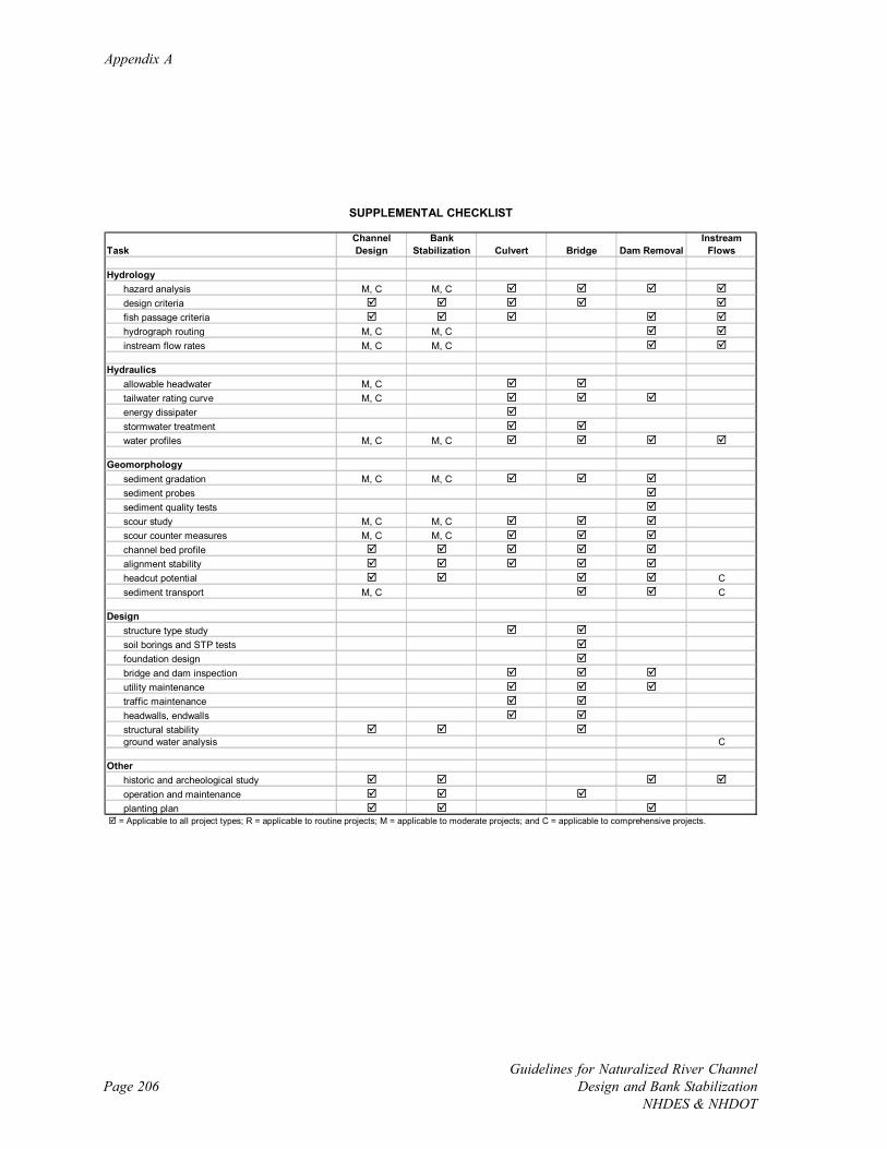
Appendix A
Page 206Guidelines for Naturalized River Channel
Design and Bank StabilizationNHDES & NHDOT
TaskChannel Design
Bank Stabilization Culvert Bridge Dam Removal
Instream Flows
Hydrologyhazard analysis M, C M, Cdesign criteriafish passage criteriahydrograph routing M, C M, Cinstream flow rates M, C M, C
Hydraulicsallowable headwater M, Ctailwater rating curve M, Cenergy dissipaterstormwater treatmentwater profiles M, C M, C
Geomorphologysediment gradation M, C M, Csediment probessediment quality testsscour study M, C M, Cscour counter measures M, C M, Cchannel bed profilealignment stabilityheadcut potential Csediment transport M, C C
Designstructure type studysoil borings and STP testsfoundation designbridge and dam inspectionutility maintenancetraffic maintenanceheadwalls, endwallsstructural stabilityground water analysis C
Otherhistoric and archeological studyoperation and maintenanceplanting plan
= Applicable to all project types; R = applicable to routine projects; M = applicable to moderate projects; and C = applicable to comprehensive projects.
SUPPLEMENTAL CHECKLIST
Page 207Guidelines for Naturalized River ChannelDesign and Bank StabilizationNHDES & NHDOT
APPENDIX B: NEW HAMPSHIRE PHOTO DOCUMENTATION PROCEDURE
Appendix B
Page 208Guidelines for Naturalized River Channel
Design and Bank StabilizationNHDES & NHDOT
Photo Documentation Procedure for
Measuring the Success of RestorationProjects and Best Management PracticesAdapted from: Products of the 2000-2001 Technical Advisory Council on Citizen Monitoring, California Association ofResource Conservation Districts, working under 319(h) contract to the State Water Resources Control Board (contractNo. 8-099-250-0)
Adapted by: Stephen Landry
Introduction:
Photographs provide a qualitative, and potentially semi-quantitative, record of conditions in awatershed or on a water body. Photographs can be used to document general conditions on a reach ofa stream during a stream walk, pollution events or other impacts, assess resource conditions overtime, or can be used to document temporal progress for restoration efforts or other projects designedto benefit water quality. Photographic technology is available to anyone and it does not require a largedegree of training or expensive equipment. Photos can be used in reports, presentations, or uploadedonto a computer website or GIS program. This approach is useful in providing a visual portrait ofwater resources to those who may never have the opportunity to actually visit a monitoring site.
Equipment:
Use the same camera to the extent possible for each photo throughout the duration of the project.Either 35 mm color or digital color cameras are recommended, accompanied by a telephoto lens. Ifyou must change cameras during the program, replace the original camera with a similar onecomparable in terms of media (digital vs. 35 mm) and other characteristics. A complete equipment listis suggested as follows:
Required:• Camera• Folder with copies of previous photos (do not carry original photos in the field)• Topographic and/or road map• Compass• Timepiece• Extra film or digital disk capacity (whichever is applicable)• Extra batteries for camera (if applicable)• Photo-log data sheets or, alternatively, a bound notebook dedicated to the project• Dry-erase board, and markers (bring extra markers)
Optional:• GPS unit• Ruler (for scale on close up views of streams and vegetation)• Wooden stakes and flags or re-bar and flags for dedicating fixed photo points in the absence of
available fixed landmarks
New Hampshire Photo Documentation Procedure
Page 209Guidelines for Naturalized River ChannelDesign and Bank StabilizationNHDES & NHDOT
Roles and Duties of Team:
The team should be comprised of two people, for restoration or other water quality improvementprojects, as follows:1. Primary Photographer responsible for selecting photo angles, targets and GPS operation.2. One person responsible for taking field notes, recording photos and preparing dry erase board.
Safety Concerns:
Persons involved in photo monitoring should ALWAYS put safety first. For safety reasons, alwayshave at least two volunteers for the survey. Make sure that the area(s) you are surveying either areaccessible to the public or that you have obtained permission from the landowner prior to the survey.
Some safety concerns that may be encountered during the survey include, but are not limited to:
• Inclement weather• Flood conditions, fast flowing water, or very cold water• Poisonous plants (e.g.: poison ivy)• Dangerous insects and animals (e.g.: bees, ticks, livestock, etc.)• Harmful or hazardous trash (e.g.: broken glass, hypodermic needles, human feces)
We recommend that the volunteer coordinator or restoration coordinator discuss the potential hazardswith all volunteers prior to any fieldwork.
General Instructions:
From the inception of any photo documentation project until it is completed, always take each photofrom the same position (photo point), and at the same bearing and vertical angle at that photo point.Photo point positions should be thoroughly documented, including photographs taken of the photopoint. Refer to copies of previous photos when arriving at the photo point. Try to maintain a level(horizontal) camera view unless the terrain is sloped. When photo points are first being selected,consider the type of project (salt marsh, wetland, or stream restoration, ambient or event monitoring,etc.) and refer to the guidance listed on Suggestions for Photo Points.
When taking photographs, try to include landscape features that are unlikely to change over severalyears (buildings, other structures, and landscape features such as peaks, rock outcrops, large trees,etc.) so that repeat photos will be easy to position. Lighting is, of course, a key ingredient so giveconsideration to the angle of light, cloud cover, background, shadows, and contrasts. Close viewphotographs taken from the north (i.e., facing south) will minimize shadows. Medium and long viewphotos are best shot with the sun at the photographer’s back. Some artistic expression is encouragedas some photos may be used on websites and in slide shows (early morning and late evening shots maybe useful for this purpose). Seasonal changes can be used to advantage as foliage, stream flow, cloudcover, and site access fluctuate. It is often important to include a ruler, person, farm animal, orautomobile in photos to convey the scale of the image. Of particular concern is the angle from whichthe photo is taken. Oftentimes an overhead or elevated shot from a bridge, peak, etc. will beinstrumental in conveying the full dimensions of the project. Of most importance overall, however, isbeing aware of the goal(s) of the project and capturing images that clearly demonstrate progresstowards achieving those goal(s). Again, reference to Suggestions for Photo Points, may be helpful.
Appendix B
Page 210Guidelines for Naturalized River Channel
Design and Bank StabilizationNHDES & NHDOT
If possible, try to include a dry-erase board in the view, marked at a minimum with the location,subject, time and date of the photograph. Use large font and position the dry-erase board in the lowercorner of each photograph. The dry erase board should be positioned at a distance from thephotographer that does not obscure the subject matter of the photo point but allows for the text to belegible. If using a digital camera (recommended), experiment on the first photo point to determine theoptimum combination of font size, distance to photographer and position of dry erase board in thephoto. Use of the flash is not recommended with the dry erase board as it tends to reflect off thesurface obscuring the text. A blank photo sign form is included in this document. Copies of this signform can be used in the photos if a dry-erase board is not available. Copying this form onto yellowsheets for field use provides the necessary contrast for the text to be visible in the photographs.
Recording Information:
Use a systematic method of recording information about each project, photo point, and photo. Thefollowing information should be entered on the photo-log forms (blank form included in thisdocument) or in a dedicated notebook:
• Project or group name, and contract number (if applicable, e.g., for funded restorationprojects)
• General location (stream, beach, city, etc.), and short narrative description of project’shabitat type, goals, etc.
• Photographer and other team members• Photo number• Date• Time (for each photograph)• Photo point information, including:
o Name or other unique identifier (abbreviated name and/or ID number)o Narrative description of location including proximity to and direction from
notable landscape features like roads, fence lines, creeks, rock outcrops, largetrees, buildings, previous photo points, etc. – sufficient for future photographerswho have never visited the project to locate the photo point
o Latitude, longitude, and altitude from map or GPS unit• Magnetic compass bearing from the photo point to the subject• Specific information about the subject of the photo• Optional additional information: a true compass bearing (corrected for declination) from
photo point to subject, time of sunrise and sunset (check newspaper or almanac), andcloud cover.
When monitoring the implementation of restoration, or Best Management Practices (BMP) projects,include or attach to the photo-log a narrative description of observable progress in achieving the goalsof the project. Provide supplementary information along with the photo, such as noticeable changes inhabitat, wildlife, and water quality and quantity. Archive all photos, along with the associated photo-log information, in a protected environment.
The Photo Point: Establishing Position of Photographer:
1. Bring a variety of methods for establishing position: maps, aerial photos, GPS, permanentmarkers and landmarks, etc. If the primary method fails (e.g., an inoperative GPS or lost markerpost) have an alternate method available.
New Hampshire Photo Documentation Procedure
Page 211Guidelines for Naturalized River ChannelDesign and Bank StabilizationNHDES & NHDOT
2. Select an existing structure or landmark (mailbox, telephone pole, benchmark, large rock, etc.),identify its latitude and longitude, and choose (and record for future use) the permanent positionof the photographer relative to that landmark. If no such permanent landmark is convenient forestablishing the photo point, the installation of grade stakes or rebar with flagging (with station IDon flagging) is recommended.
3. For restoration, and BMP projects, photograph the photo-points and carry copies of thosephotographs on subsequent field visits.
Determining the Compass Bearing:
1. Select and record the true compass bearing of the photo center view. Include a prominentlandmark in a set position within the view. If possible, have an assistant stand at a fixed distancefrom both the photographer and the center of the view, holding the dry-erase board for scale.
2. When performing ambient or event photo monitoring, and when a compass is not available, thenrefer to a map and record the approximate bearing as north, south, east or west.
Suggestions for Photo Points:
1. When first beginning a monitoring program take representative long and/or medium view photosof stream reaches, segments of shoreline or other areas being monitored. Show the positions ofthese photos on a map or site sketch. Subjects to be photographed include a representative view ofthe stream or shore condition at the beginning and ending positions of the segment beingmonitored, storm drain outfalls, confluence of tributaries, structures (e.g., bridges, dams, culverts,etc.).
2. If possible, take a close view photograph of the substrate (streambed), algae, or submergedaquatic vegetation.
3. Take long view and medium view of streambed changes (thalweg, gravel, meanders, etc.)
4. Time series: Take photos immediately before and after construction, planting, or vegetationremoval. Take medium and close views of structures, plantings, etc. Long term monitoring shouldallow for at least annual photography.
5. Event monitoring: this refers to any unusual or sporadic conditions encountered during a streamor shore walk, such as trash dumps, turbidity events, oil spills, etc. Photograph and recordinformation on your photo-log. Report pollution events to the NH Department of EnvironmentalServices (603-271-3503).
6. Optional: Use a tape set perpendicular across the stream channel at fixed points and include thistape in your photos. The tape will show the current depth of the stream relative to the tape.
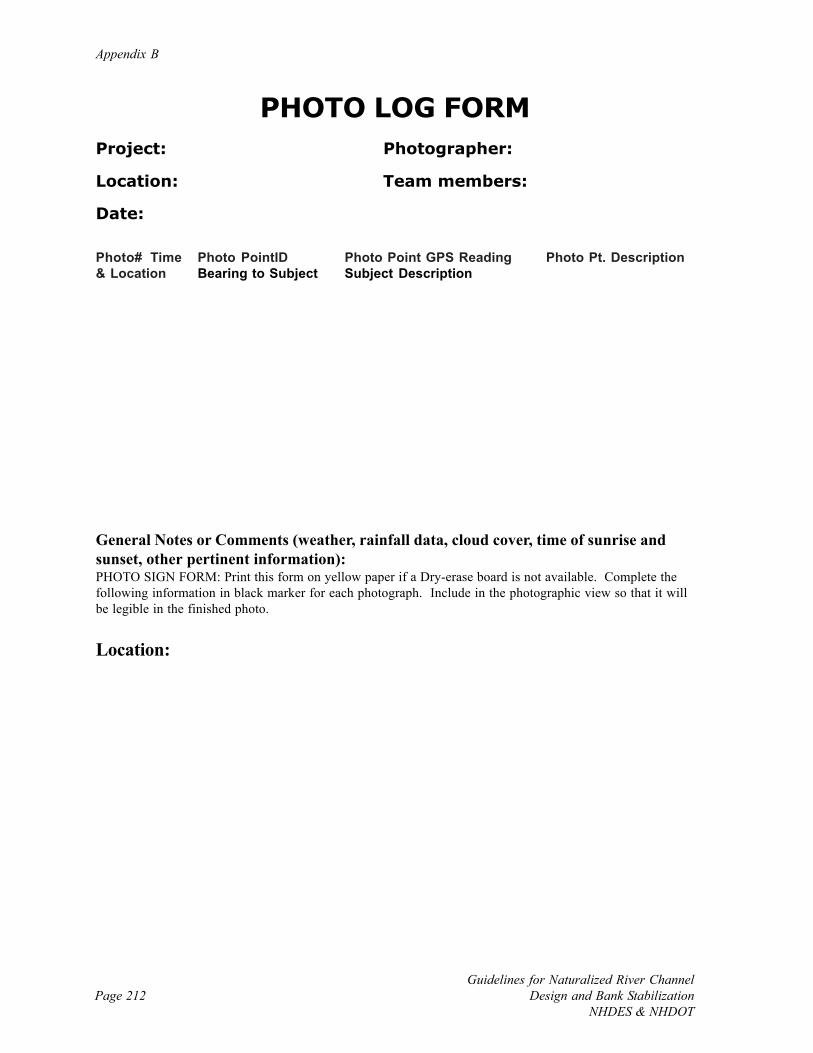
Appendix B
Page 212Guidelines for Naturalized River Channel
Design and Bank StabilizationNHDES & NHDOT
PHOTO LOG FORMProject: Photographer:
Location: Team members:
Date:
Photo# Time Photo PointID Photo Point GPS Reading Photo Pt. Description& Location Bearing to Subject Subject Description
General Notes or Comments (weather, rainfall data, cloud cover, time of sunrise andsunset, other pertinent information):PHOTO SIGN FORM: Print this form on yellow paper if a Dry-erase board is not available. Complete thefollowing information in black marker for each photograph. Include in the photographic view so that it willbe legible in the finished photo.
Location:

New Hampshire Photo Documentation Procedure
Page 213Guidelines for Naturalized River ChannelDesign and Bank StabilizationNHDES & NHDOT
Subject Description:
Date:
Time:

Appendix B
Page 214Guidelines for Naturalized River Channel
Design and Bank StabilizationNHDES & NHDOT
[Page intentionally left blank.]
Page 215Guidelines for Naturalized River ChannelDesign and Bank StabilizationNHDES & NHDOT
APPENDIX C: NEW HAMPSHIRE GAGE NETWORK AND HUC-10 CODES
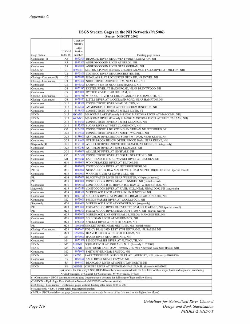
Appendix C
Page 216Guidelines for Naturalized River Channel
Design and Bank StabilizationNHDES & NHDOT
Gage StatusHUC-10 Index (6)
USGS or NHDES
Gage Station number Existing gage names
Continuous (1) A3 1052500 DIAMOND RIVER NEAR WENTWORTH LOCATION, NH Continuous A5 1053500 ANDROSCOGGIN RIVER AT ERROL, NH Continuous A5 1054000 ANDROSCOGGIN RIVER NEAR GORHAM, NH HDCN (2) C1 SFMNH MILTON 3-PONDS (Formerly 01072100 SALMON FALLS RIVER AT MILTON, NH)Continuous C2 1072800 COCHECO RIVER NEAR ROCHESTER, NH. Closing - Continuous(3) C2 1072870 ISINGLASS R AT ROCHESTER NECK RD, NR DOVER, NH Closing - Continuous C3 1073460 NORTH RIVER ABOVE NH 125, NEAR LEE, NH Continuous C3 1073500 LAMPREY RIVER NEAR NEWMARKET, NH Continuous C4 1073587 EXETER RIVER AT HAIGH ROAD, NEAR BRENTWOOD, NH Continuous C5 1073000 OYSTER RIVER NEAR DURHAM, NH Closing - Continuous C5 1073785 WINNICUT RIVER AT GREENLAND, NR PORTSMOUTH, NH Closing - Continuous C6 1073822 LITTLE RIVER AT WOODLAND ROAD, NEAR HAMPTON, NH Continuous Ct10 1131500 CONNECTICUT RIVER NEAR DALTON, NH Continuous Ct12 1137500 AMMONOOSUC RIVER AT BETHLEHEM JUNCTION, NH Continuous Ct14 1138500 CONNECTICUT RIVER AT WELLS RIVER, VT HDCN Ct17 MCAN3 MASCOMA LAKE (Formerly 01150500 MASCOMA RIVER AT MASCOMA, NH)HDCN Ct17 WCNN3 MASCOMA RIVER (Formerly 01145000 MASCOMA RIVER AT WEST CANAAN, NH)Continuous Ct18 1144500 CONNECTICUT RIVER AT WEST LEBANON, NH Continuous Ct19 1152500 SUGAR RIVER AT WEST CLAREMONT, NH Continuous Ct2 1129200 CONNECTICUT R BELOW INDIAN STREAM NR PITTSBURG, NH Continuous Ct22 1154500 CONNECTICUT RIVER AT NORTH WALPOLE, NH Continuous Ct23 1158000 ASHUELOT RIVER BELOW SURRY MT DAM, NEAR KEENE, NH Continuous Ct24 1158600 OTTER BROOK BELOW OTTER BROOK DAM, NEAR KEENE, NH Stage-only (4) Ct25 1158110 ASHUELOT RIVER ABOVE THE BRANCH, AT KEENE, NH (stage only)Continuous Ct26 1160350 ASHUELOT RIVER AT WEST SWANZEY, NH Continuous Ct26 1161000 ASHUELOT RIVER AT HINSDALE, NH Continuous Ct5 1129500 CONNECTICUT RIVER AT NORTH STRATFORD, NH Continuous M1 1074520 EAST BRANCH PEMIGEWASSET RIVER AT LINCOLN, NH Continuous M10 1081000 WINNIPESAUKEE RIVER AT TILTON, NH Continuous M11 1082000 CONTOOCOOK RIVER AT PETERBOROUGH, NH PR (5) M11 1083000 NUBANUSIT BK BLW MACDOWELL DAM NR PETERBOROUGH NH (partial record0Continuous M13 1086000 WARNER RIVER AT DAVISVILLE, NH PR M14 1087000 BLACKWATER RIVER NEAR WEBSTER, NH (partial record)PR M15 1085000 CONTOOCOOK RIVER NEAR HENNIKER, NH (partial record)Continuous M15 1085500 CONTOOCOOK R BL HOPKINTON DAM AT W HOPKINTON, NH Stage-only M15 1087850 CONTOOCOOK RIVER AT RIVER HILL, NEAR PENACOOK, NH (stage only)Continuous M18 1081500 MERRIMACK RIVER AT FRANKLIN JUNCTION, NH Continuous M19 1089100 SOUCOOK RIVER, AT PEMBROKE ROAD, NEAR CONCORD, NH Continuous M2 1075000 PEMIGEWASSET RIVER AT WOODSTOCK, NH Stage-only M20 1088400 MERRIMACK RIVER AT CONCORD, NH (stage only)PR M23 1090800 PISCATAQUOG RIVER BL EVERETT DAM, NR E WEARE, NH (partial record)PR M23 1091500 PISCATAQUOG RIVER NEAR GOFFSTOWN, NH (partial record)Continuous M25 1092000 MERRIMACK R NR GOFFS FALLS, BELOW MANCHESTER, NH Continuous M26 1094000 SOUHEGAN RIVER AT MERRIMACK, NH Continuous M28 1100505 SPICKET RIVER AT NORTH SALEM, NH PR M28 1100561 SPICKET RIVER NEAR METHUEN, MA (partial record)Closing - Continuous M28 11005605 POLICY BR @ I-93N REST STOP ENT RAMP, NR SALEM, NH Continuous M29 10965852 BEAVER BROOK AT NORTH PELHAM, NH Continuous M3 1076000 BAKER RIVER NEAR RUMNEY, NH Continuous M4 1076500 PEMIGEWASSET RIVER AT PLYMOUTH, NH HDCN M5 ASHNH SQUAM RIVER AT ASHLAND, N.H. (formerly 01077000)HDCN M6 NFLNH NEWFOUND LAKE DAM (formerly 01077500 Newfound Lake Near Bristol, NH)Continuous M7 1078000 SMITH RIVER NEAR BRISTOL, NH HDCN M9 LKPN3 LAKE WINNIPESAUKEE OUTLET AT LAKEPORT, N.H. (formerly 01080500)Continuous S3 1064500 SACO RIVER NEAR CONWAY, NH Continuous S5 1064801 BEARCAMP RIVER AT SOUTH TAMWORTH, NH HDCN S8 OSRNH OSSIPEE RIVER AT EFFINGHAM FALLS, N.H. (formerly 01065000)
USGS Stream Gages in the NH Network (9/15/06)
(6) Index - for this study USGS HUC-10 numbers were renamed with the first letter of their major basin and sequential numbering.A=Androscoggin, C=Coastal, Ct=Connecticut, M=Merrimack, S=Saco
(1) Continuous = USGS continuous record gage (measurements accurate for full range of high and low flows)
(Source: NHSGTF, 2006)
(2) HDCN = Hydrologic Data Collection Network (NHDES Dam Bureau station)(3) Closing - Continuous = Continuous gages without funding after either 2006 or 2007(4) Stage-only = USGS water height measurement station(5) PR = USGS partial record gage (measurements accurate only for some of the data such as the high or low flows)
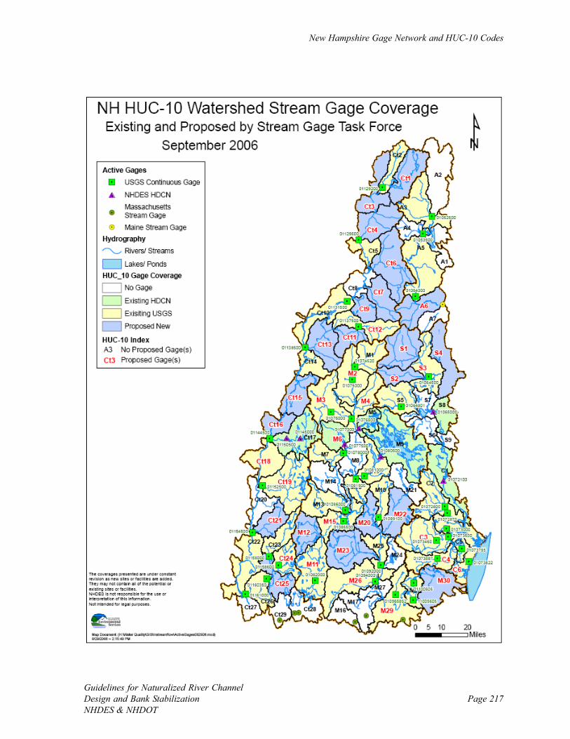
New Hampshire Gage Network and HUC-10 Codes
Page 217Guidelines for Naturalized River ChannelDesign and Bank StabilizationNHDES & NHDOT

Appendix C
Page 218Guidelines for Naturalized River Channel
Design and Bank StabilizationNHDES & NHDOT
DES DAM BUREAU GAGES
(Visit http://des.nh.gov/rti_home/ for data)
Winnipesaukee River Basin
Smith River near Bristol Merrimack River at FranklinGilmanton Lakeport Dam at LakeportWinnisquam Lake at Winnisquam Opechee Bay at LaconiaPoorfarm Brook at Ellacoya State Park Shannon Brook near MoultonboroughSilver Lake at Lochmere Winnipesaukee River at TiltonLake Winnipesaukee at Weirs Beach Wolfeboro
Pemigewasset River and Ossipee Lake Basins
Squam River near Ashland Bearcamp River at South TamworthFranklin Falls Dam at Franklin East Br Pemigewasset River at LincolnNewfound Lake near Bristol Ossipee Lake near West OssipeeOssipee River at Effingham Falls Pemigewasset River at PlymouthBaker River near Rumney Squam Lake near AshlandPemigewasset River at Woodstock
Mascoma, Suncook, Salmon Falls, Powwow, and Piscataquog River Basins
Blackwater Dam near Webster Merrimack River at ConcordExeter River near Brentwood Piscataquog River near GoffstownMerrimack River near Goffs Falls Contoocook River at HennikerLamprey River near Newmarket Mascoma Lake Dam & Mascoma River at MascomaOyster River near Durham Contoocook River near River HillMilton 3-Ponds & Salmon Falls River at Milton Soucook River near ConcordSunapee Lake at Sunapee Harbor Blackwater River near WebsterMascoma River at West Canaan Everett Lake Dam & Piscataquog River near WeareHopkinton Lake Dam & Contoocook River Connecticut River at West Lebanonat Hopkinton
Weekly Lake Elevation Stations
Angle Pond (Sandown) Barnstead Parade (Barnstead)Buck Street (Allenstown) Crystal Lake (Enfield)Crystal Lake (Gilmanton) Kingswood Lake (Brookfield)Deering Reservoir (Deering) Great East Lake (Wakefield)Goose Pond (Canaan) Grafton Pond (Grafton)Great Pond (Kingston) Horace Lake (Weare)Horn Pond (Wakefield) Lovell Lake (Wakefield)Northwood Lake (Northwood) Powwow Pond (East Kingston)Sunset Lake (Alton) Suncook Lake (Barnstead)
New Hampshire Gage Network and HUC-10 Codes
Page 219Guidelines for Naturalized River ChannelDesign and Bank StabilizationNHDES & NHDOT
Available References (Source: NHSGTF, 2006)
New Hampshire’s Stream-gaging Network: Status and Future Needs by S.A. Olson, FS-050-03, http://pubs.usgs.gov/fs/fs-050-03/pdf/FS050-03_508.pdf
Effectiveness of the New Hampshire Stream-gaging Network in Providing Regional Streamflow Informationby S.A. Olson, WRIR 03-4041http://pubs.usgs.gov/wri/wrir03-4041/
A Stream-gaging Network Analysis for the 7-Day, 10-Year Annual Low Flow in New Hampshire Streams byR.H. Flynn, WRIR 03-4023http://pubs.usgs.gov/wri/wrir03-4023/
Development of Regression Equations to Estimate Flow Durations and Low-Flow-Frequency Statistics inNew Hampshire Streams by R.H. Flynn, WRIR 02-4298http://pubs.usgs.gov/wri/wri02-4298/
The New Hampshire Watershed Tool: A Geographic Information System Tool toEstimate Streamflow Statistics and Ground-Water Recharge Rates by S.A. Olson, R.H. Flynn, C.M.Johnston, and G.D. Tasker, OFR 2005-1172http://pubs.usgs.gov/of/2005/1172/
Cost Effectiveness of the U.S. Geological Survey’s Stream-Gaging Programs in New Hampshire and Vermontby J.A. Smath and F.E. Blackey, WRIR 85-4173
Expansion of the USGS Cooperative Streamgage Network in Massachusettshttp://ma.water.usgs.gov/nwis/images/eoea.expansion.htm
New Hampshire-Vermont Water Science Center Newsletter, April 2006, USGS publication,http://nh.water.usgs.gov/Publications/online_publications.htm
List of gages discontinued in 2004:http://nh.water.usgs.gov/WaterData/NHdiscont05.htm
Rivers Management Advisory Committee Strategy for Stream Gaging in New Hampshire, December 20,2005
Rivers Management Advisory Committee Recommendations For Stream Gaging In New Hampshire To theCommissioner of the Department of Environmental Services, December 20, 2005
Footnotes:[1] Rivers are designated under RSA 483: New Hampshire Rivers Management and Protection Program.There are 14 rivers in NH designated for special protections because of their unique and outstandingcharacteristics.http://www.des.state.nh.us/rivers/rsa483.htm
[2] The USGS’s Hydrologic Unit Codes are numbers that divide the nation’s watersheds on a hierarchicalbasis with an increasing number of digits from regional to more local watersheds. The Merrimack basin hasa four-digit HUC (0107) and therefore is a HUC-4. In the Merrimack basin, HUC-0107000609 (a ten-digitHUC) is the Souhegan watershed, which is a subdivision of the Merrimack watershed. New Hampshire ispart of four HUC-4s, but is part of 81 HUC-10s. For simplicity of mapping in this report these 10-digitHUCs were renamed with HUC index values made up of a letter indicating the major water watershed andsequential numbering.
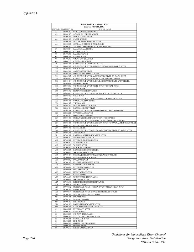
Appendix C
Page 220Guidelines for Naturalized River Channel
Design and Bank StabilizationNHDES & NHDOT
HUC Index USGS HUC_10 HUC_10_NAME A1 104000102 UMBAGOG LAKE DRAINAGE A2 104000103 AZISCOHOS LAKE DRAINAGE A3 104000104 MAGALLOWAY RIVER A4 104000105 CLEAR STREAM A5 104000106 MIDDLE ANDROSCOGGIN RIVER A6 104000201 GORHAM-SHELBURNE TRIBUTARIES A7 104000202 ANDROSCOGGIN RIVER AT RUMFORD POINT C1 106000304 SALMON FALLS RIVER C2 106000306 COCHECO RIVER C3 106000307 LAMPREY RIVER C4 106000308 EXETER RIVER C5 106000309 GREAT BAY DRAINAGE C6 106000310 COASTAL DRAINAGE Ct1 108010101 CONNECTICUT LAKES DRAINAGE
Ct10 108010302 CONNECTICUT RIVER-JOHNS RIVER TO AMMONOOSUC RIVER Ct11 108010303 GALE RIVER Ct12 108010304 AMMONOOSUC RIVER Ct13 108010305 LOWER AMMONOOSUC RIVER Ct14 108010307 CONNECTICUT RIVER-AMMONOOSUC RIVER TO WAITS RIVER Ct15 108010402 CONNECTICUT RIVER-WAITS RIVER TO HEWES BROOK Ct16 108010404 CONNECTICUT RIVER-OMPOMPANOOSUC RIVER TO WHITE RIVER Ct17 108010601 MASCOMA RIVER Ct18 108010603 CONNECTICUT RIVER-WHITE RIVER TO SUGAR RIVER Ct19 108010604 SUGAR RIVER Ct2 108010102 HEADWATER TRIBUTARIES
Ct20 108010607 CONNECTICUT RIVER-SUGAR RIVER TO BELLOWS FALLS Ct21 108010702 COLD RIVER Ct22 108010705 CONNECTICUT RIVER-BELLOWS FALLS TO VERNON DAM Ct23 108020101 UPPER ASHUELOT RIVER Ct24 108020102 THE BRANCH Ct25 108020103 MIDDLE ASHUELOT RIVER Ct26 108020104 LOWER ASHUELOT RIVER Ct27 108020105 CONNECTICUT RIVER-VERNON DAM TO DEERFIELD RIVER Ct28 108020201 UPPER MILLERS RIVER Ct29 108020202 LOWER MILLERS RIVER Ct3 108010103 MOHAWK RIVER-STEWARTSTOWN TRIBUTARIES Ct4 108010104 CONNECTICUT RIVER-MOHAWK RIVER TO NULHEGAN RIVER Ct5 108010106 CONNECTICUT RIVER-NULHEGAN RIVER TO UPPER AMMONOOSUC RIVER Ct6 108010107 UPPER AMMONOOSUC RIVER Ct7 108010108 ISRAEL RIVER Ct8 108010109 CONNECTICUT RIVER-UPPER AMMONOOSUC RIVER TO JOHNS RIVER Ct9 108010301 JOHNS RIVER M1 107000101 EAST BRANCH PEMIGEWASSET RIVER M10 107000202 WINNIPESAUKEE RIVER M11 107000301 UPPER CONTOOCOOK RIVER M12 107000302 NORTH BRANCH M13 107000303 WARNER RIVER M14 107000304 BLACKWATER RIVER M15 107000305 LOWER CONTOOCOOK RIVER M16 107000403 SQUANNACOOK RIVER M17 107000404 NASHUA RIVER-SQUANNACOOK RIVER TO MOUTH M18 107000601 UPPER MERRIMACK RIVER M19 107000602 SOUCOOK RIVER M2 107000102 UPPER PEMIGEWASSET RIVER M20 107000603 CONCORD TRIBUTARIES M21 107000604 UPPER SUNCOOK RIVER M22 107000605 SUNCOOK RIVER M23 107000606 PISCATAQUOG RIVER M24 107000607 COHAS BROOK M25 107000608 MANCHESTER TRIBUTARIES M26 107000609 SOUHEGAN RIVER M27 107000610 LITCHFIELD-HUDSON TRIBUTARIES M28 107000611 SPICKETT RIVER M29 107000612 MERRIMACK RIVER-NASHUA RIVER TO SHAWSHEEN RIVER M3 107000103 BAKER RIVER M30 107000614 MERRIMACK RIVER-SHAWSHEEN RIVER TO MOUTH M4 107000104 MIDDLE PEMIGEWASSET RIVER M5 107000105 SQUAM RIVER M6 107000106 NEWFOUND RIVER M7 107000107 SMITH RIVER M8 107000108 LOWER PEMIGEWASSET RIVER M9 107000201 LAKE WINNIPESAUKEE DRAINAGE S1 106000201 UPPER SACO RIVER S2 106000202 SWIFT RIVER S3 106000203 CONWAY TRIBUTARIES S4 106000204 SACO RIVER-LOVEWELL POND S5 106000206 BEARCAMP RIVER S6 106000207 PINE RIVER S7 106000208 OSSIPEE LAKE DRAINAGE S8 106000209 OSSIPEE RIVER S9 106000210 LITTLE OSSIPEE RIVER
Table A4-HUC-10 Index Key (Source: NHSGTF, 2006)
Page 221Guidelines for Naturalized River ChannelDesign and Bank StabilizationNHDES & NHDOT
APPENDIX D: NATIONAL FLOOD FREQUENCY HYDROLOGY MODEL FOR
NEW HAMPSHIRE
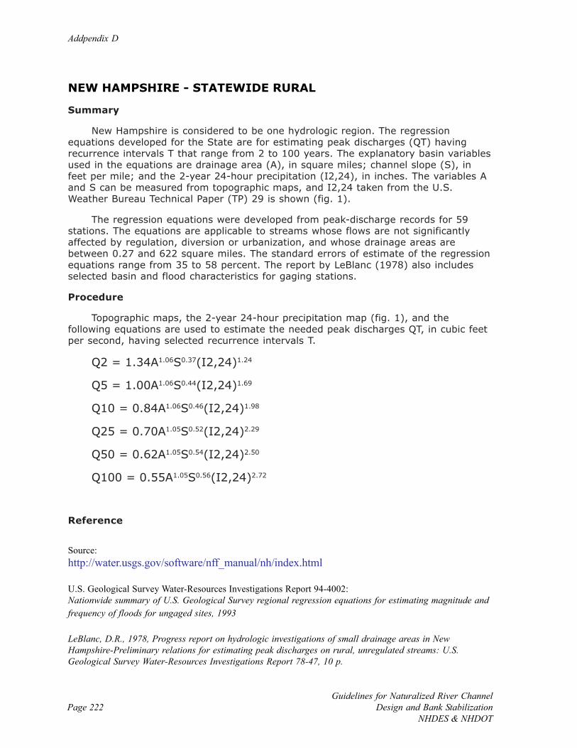
Addpendix D
Page 222Guidelines for Naturalized River Channel
Design and Bank StabilizationNHDES & NHDOT
NEW HAMPSHIRE - STATEWIDE RURAL
Summary
New Hampshire is considered to be one hydrologic region. The regressionequations developed for the State are for estimating peak discharges (QT) havingrecurrence intervals T that range from 2 to 100 years. The explanatory basin variablesused in the equations are drainage area (A), in square miles; channel slope (S), infeet per mile; and the 2-year 24-hour precipitation (I2,24), in inches. The variables Aand S can be measured from topographic maps, and I2,24 taken from the U.S.Weather Bureau Technical Paper (TP) 29 is shown (fig. 1).
The regression equations were developed from peak-discharge records for 59stations. The equations are applicable to streams whose flows are not significantlyaffected by regulation, diversion or urbanization, and whose drainage areas arebetween 0.27 and 622 square miles. The standard errors of estimate of the regressionequations range from 35 to 58 percent. The report by LeBlanc (1978) also includesselected basin and flood characteristics for gaging stations.
Procedure
Topographic maps, the 2-year 24-hour precipitation map (fig. 1), and thefollowing equations are used to estimate the needed peak discharges QT, in cubic feetper second, having selected recurrence intervals T.
Q2 = 1.34A1.06S0.37(I2,24)1.24
Q5 = 1.00A1.06S0.44(I2,24)1.69
Q10 = 0.84A1.06S0.46(I2,24)1.98
Q25 = 0.70A1.05S0.52(I2,24)2.29
Q50 = 0.62A1.05S0.54(I2,24)2.50
Q100 = 0.55A1.05S0.56(I2,24)2.72
Reference
Source:http://water.usgs.gov/software/nff_manual/nh/index.html
U.S. Geological Survey Water-Resources Investigations Report 94-4002:Nationwide summary of U.S. Geological Survey regional regression equations for estimating magnitude andfrequency of floods for ungaged sites, 1993
LeBlanc, D.R., 1978, Progress report on hydrologic investigations of small drainage areas in NewHampshire-Preliminary relations for estimating peak discharges on rural, unregulated streams: U.S.Geological Survey Water-Resources Investigations Report 78-47, 10 p.
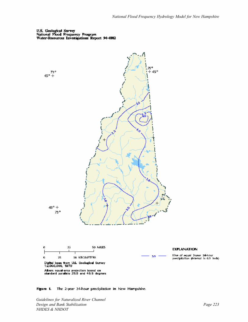
National Flood Frequency Hydrology Model for New Hampshire
Page 223Guidelines for Naturalized River ChannelDesign and Bank StabilizationNHDES & NHDOT

Addpendix D
Page 224Guidelines for Naturalized River Channel
Design and Bank StabilizationNHDES & NHDOT
[Page intentionally left blank.]

Page 225Guidelines for Naturalized River ChannelDesign and Bank StabilizationNHDES & NHDOT
APPENDIX E: CHARTS FOR DETERMINING STABLE EQUILIBRIUM SLOPE
Appendix E
Page 226Guidelines for Naturalized River Channel
Design and Bank StabilizationNHDES & NHDOT
(USACOE, 1994)
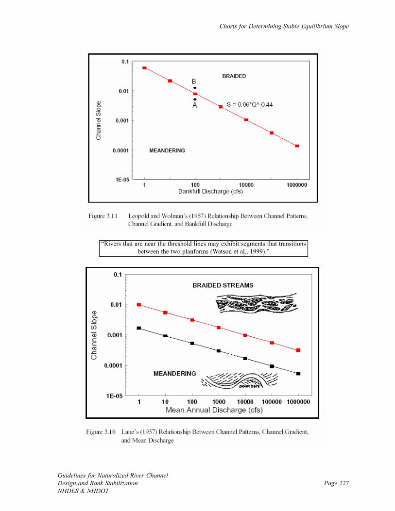
Charts for Determining Stable Equilibrium Slope
Page 227Guidelines for Naturalized River ChannelDesign and Bank StabilizationNHDES & NHDOT
“Rivers that are near the threshold lines may exhibit segments that transitionsbetween the two planforms (Watson et al., 1999).”
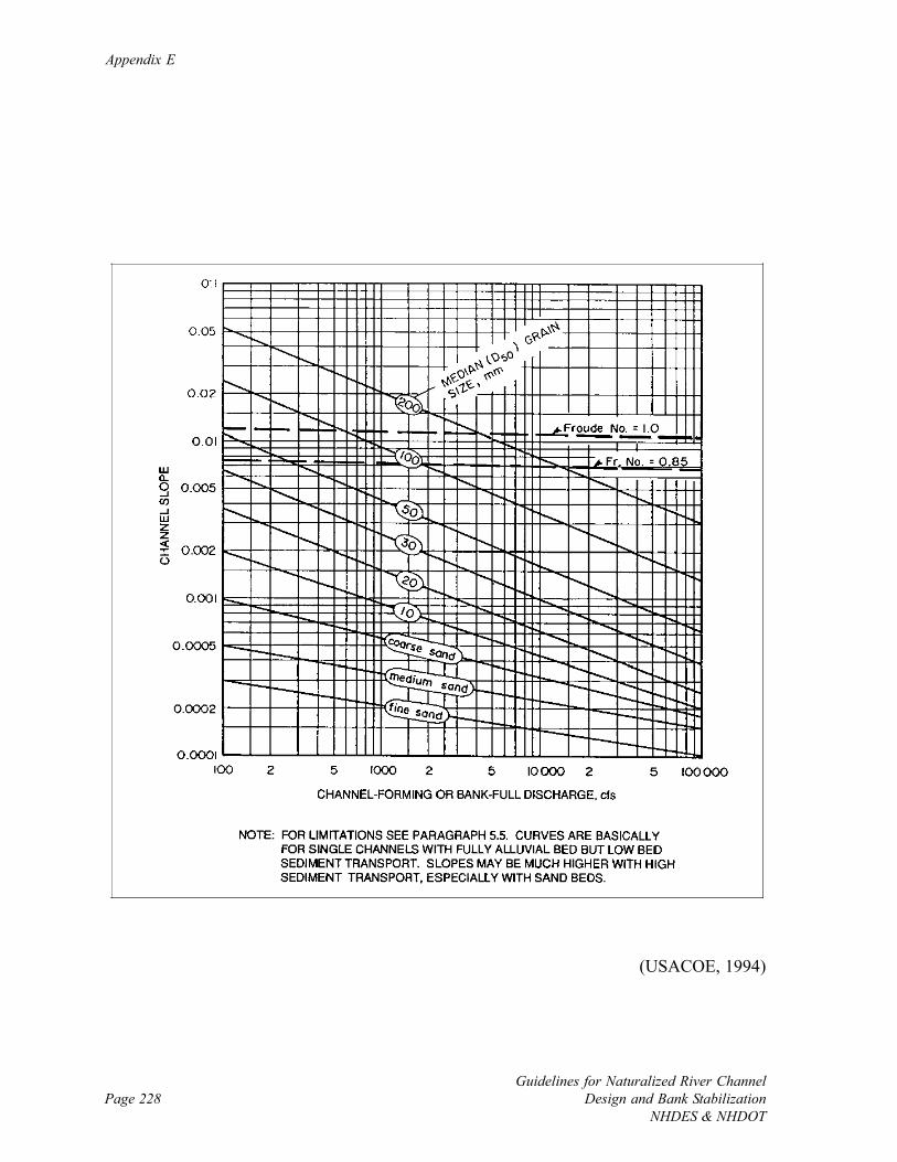
Appendix E
Page 228Guidelines for Naturalized River Channel
Design and Bank StabilizationNHDES & NHDOT
(USACOE, 1994)

Page 229Guidelines for Naturalized River ChannelDesign and Bank StabilizationNHDES & NHDOT
APPENDIX F: CHARTS FOR DETERMINING THRESHOLD VELOCITY
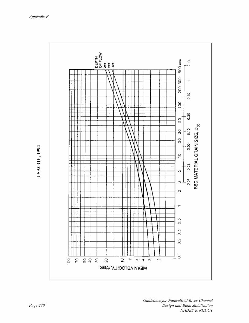
Appendix F
Page 230Guidelines for Naturalized River Channel
Design and Bank StabilizationNHDES & NHDOT
USA
CO
E, 1
994
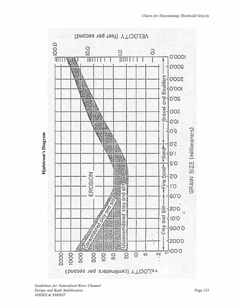
Charts for Determining Threhsold Velocity
Page 231Guidelines for Naturalized River ChannelDesign and Bank StabilizationNHDES & NHDOT
Hju
lstr
om’s
Dia
gram

Appendix F
Page 232Guidelines for Naturalized River Channel
Design and Bank StabilizationNHDES & NHDOT
[Page intentionally left blank.]
Page 233Guidelines for Naturalized River ChannelDesign and Bank StabilizationNHDES & NHDOT
APPENDIX G: NEW HAMPSHIRE DESIGNATED RIVERS UNDER RSA 483

Appendix G
Page 234Guidelines for Naturalized River Channel
Design and Bank StabilizationNHDES & NHDOT
New Hampshire Designated Rivers Under RSA 483
Page 235Guidelines for Naturalized River ChannelDesign and Bank StabilizationNHDES & NHDOT
What is a designated river?
A river managed and protected for its outstanding natural and cultural resources inaccordance with RSA 483 - The Rivers Management & Protection Act.
New Hampshire’s Designated Rivers
Ashuelot River
From the dam at Butterfield Pond in Washington to the confluence with theConnecticut River in Hinsdale. Effective 6/7/93. Municipalities: Washington, Lempster,Marlow, Gilsum, Sullivan, Surry, Keene, Swanzey, Winchester, and Hinsdale.
Cold River
From the outlet of Crescent Lake Dam in Acworth to its confluence with theConnecticut River in Walpole. Effective 07/20/99. Municipalities: Acworth, Lempster,Langdon, Alstead, and Walpole.
Connecticut River
From the outlet of Fourth Connecticut Lake to the New Hampshire/Massachusetts stateline. Effective 7/14/92. Municipalities: Pittsburg, Clarksville, Stewartstown, Colebrook,Columbia, Stratford, Northumberland, Lancaster, Dalton, Littleton, Monroe, Bath,Haverhill, Piermont, Orford, Lyme, Hanover, Lebanon, Plainfield, Cornish, Claremont,Charlestown, Walpole, Westmoreland, Chesterfield, and Hinsdale.
Contoocook River - Mainstem and North Branch
Mainstem - From the outlet of Poole Pond in Rindge to the confluence with theMerrimack River at the Boscawen/Concord municipal boundary. North Branch - Fromthe outlet of Rye Pond in Stoddard to the confluence of the Contoocook River inHillsborough. Effective 6/28/91. Municipalities: Rindge, Jaffrey, Peterborough,Hancock, Greenfield, Bennington, Stoddard, Antrim, Deering, Hillsborough, Henniker,Hopkinton, Concord, and Boscawen.
Exeter River
From the headwaters at the Route 102 bridge in Chester to its confluence with GreatBrook in Exeter. Effective 8/11/95. Municipalities: Chester, Sandown, Danville,Fremont, Raymond, Brentwood, and Exeter.
Isinglass River
From the outflow of Bow Lake Dam in Strafford to its confluence with the CochecoRiver in Rochester. Effective 6/30/02. Municipalities: Strafford, Barrington, Rochester.
Lamprey River
From the Epping/Lee town line to the Durham/Newmarket town line. Effective 6/26/90. Municipalities: Lee and Durham.
Merrimack River - Lower
From the Bedford/Merrimack town line to the New Hampshire/Massachusetts stateline. Effective 6/26/90. Municipalities: Merrimack, Litchfield, Nashua and Hudson.
Appendix G
Page 236Guidelines for Naturalized River Channel
Design and Bank StabilizationNHDES & NHDOT
Merrimack River - Upper
From the confluence of the Winnipesaukee and Pemigewasset Rivers in Franklin toGarvins Falls in Bow. Effective 6/26/90. Municipalities: Franklin, Northfield, Boscawen,Canterbury, Concord, and Bow.
Pemigewasset River
From the outlet of Profile Lake in Franconia Notch State Park to the southern boundaryof Franconia Notch State Park and from the northernmost Thornton town line to theconfluence with the Merrimack River in Franklin. Effective 6/28/91. Municipalities:Franconia Notch State Park, Franconia, Thornton, Campton, Plymouth, Holderness,Ashland, Bridgewater, New Hampton, Bristol, Hill, Sanbornton, and Franklin.
Piscataquog River - South, Middle and North Branches
North Branch—From the outlet of Deering Lake Dam in Deering to the confluence withthe South Branch in Goffstown (omitting Lake Horace and Everett Flood Control Area).South Branch—From the outlet of Pleasant Pond in Francestown to the river’s mouth atBass Island in Manchester. Middle Branch—From the outlet of Scobie Pond inFrancestown to the confluence with the South Branch in New Boston. Effective 7/16/93. Municipalities: Deering, Weare, New Boston, Francestown, Lyndeborough,Goffstown, and Manchester.
Saco River
From the base of Saco Lake dam in Crawford Notch State Park to the New Hampshire/Maine state line. Effective 6/26/90. Municipalities: Crawford Notch State Park, HartsLocation, Bartlett, and Conway.
Souhegan River
From the confluence of the south and west branches in New Ipswich to the confluencewith the Merrimack River in Merrimack. Effective May 28, 2000. Municipalities: NewIpswich, Greenville, Wilton, Milford, Amherst, Merrimack.
Swift River
From its headwaters in Livermore to its confluence with the Saco River in Conway.Effective 6/26/90. Municipalities: White Mountain National Forest, Livermore,Waterville Valley, Albany, and Conway.
Page 237Guidelines for Naturalized River ChannelDesign and Bank StabilizationNHDES & NHDOT
GLOSSARY OF TECHNICAL TERMS
1.5-year flow – Often approximated as the channel-forming, bankfull, or effective discharge
because of its large contribution to sediment transport and channel shaping. The flood of a
magnitude that is expected to be equaled or exceeded, on average, once during any 1.5-year
period. The 1.5-year flood has a 67 percent chance of being equaled or exceeded in any given
year.
100-year flow – The flood of a magnitude that is expected to be equaled or exceeded, on
average, once during any 100-year period. The 100-year flood has a 1 percent chance of
being equaled or exceeded in any given year.
10-year flow – The flood of a magnitude that is expected to be equaled or exceeded, on
average, once during any 10-year period. The 10-year flood has a 10 percent chance of being
equaled or exceeded in any given year.
Adaptive management – When results are utilized in a feedback loop to adjust activities and
goals associated with a monitoring project (Holling, 1978).
Aggradation – The building up of the river channel due to the deposition of sediment
materials on the channel bed. This process can lead to channel widening if the flow area in the
channel is reduced enough that flow is pushed towards the banks.
Alluvial – Transported by flowing water. The transported material itself is called alluvium
(Merriam-Webster’s Collegiate Dictionary). An alluvial river channel is one that is formed
from the constant erosion and deposition of alluvium in a dynamic balance between sediment
and water, and thus can be prone to channel instability when disturbed.
Glossary
Page 238Guidelines for Naturalized River Channel
Design and Bank StabilizationNHDES & NHDOT
Analog – An approach to naturalized channel design and bank stabilization where stable
channel dimensions at a single dominant design discharge at the project site are determined
from observation of the geomorphic characteristics of a nearby stable reference reach.
Analytical – An approach to naturalized channel design and bank stabilization where
characteristics of the project site such as cross-sectional discharge, stable channel dimensions,
or sediment transport rates are approximated via physical-based equations or models.
Aquatic ecosystem – The combination of physical, chemical, and biological structure (e.g.,
substrate, habitat, biological communities) and process (e.g., sediment transport, nutrient
cycling, and drift) taking place in rivers and other surface waters.
AutoCAD – A computer-assisted drafting and design tool.
Autotrophic inputs – Originating within the river channel, such as the primary production by
aquatic plants at the bottom of the food web.
Avulsion – The sudden creation of a new river channel where flow leaves the existing channel
during large floods and carves a new channel with a new slope and length. Avulsions typically
occur when flood waters carve a new flow path across a sharp meander bend, access a nearby
low spot such as an old gravel pit, impinge on the banks due to the formation of a large debris
jam, or overtop an under-sized channel.
BACI – Before-after-control-impact (Stewart-Oaten et al., 1986). A popular study design to
evaluate the effects of river management activates where both control and impact sites are
monitored before and after a treatment.
Glossary
Page 239Guidelines for Naturalized River ChannelDesign and Bank StabilizationNHDES & NHDOT
Backwater – The backing-up of water due to a constriction where flow velocities and
sediment transport decrease and water surface elevations increase. A common example of
backwatering is when water ponds upstream of an undersized bridge or culvert leading to
channel aggradation, widening, and instability. Backwater also regularly occurs near the
confluence of a tributary and larger mainstem river due to higher flows on the larger river.
Bank angle – The angle between the water surface and a river bank. 90o represents a vertical
bank, smaller angles indicate overhanging banks, and larger angles represent less steep banks.
Bank armoring – The application of hard materials to riverbanks to fix them in place,
reducing or eliminating lateral channel migration that takes place in a naturally meandering
river. Armoring is often carried out with riprap, and if applied over large portions of a river
can lead to channel instability in other locations as water, sediment, and energy is reflected to
downstream river locations. This is often called “chasing the river.” Bank armoring is a
temporary fix where the source of the problem in the watershed remains unaddressed.
Bank logs – Logs that are located either perpendicular or parallel to the riverbank that act as
barriers to bank erosion and offer near-bank habitat for macroinvertebrates and fish. The term
bank logs typically is reserved for material naturally finding its way to the river banks, whereas
log revetment and root wad revetment are often used to signify installed practices.
Bank soil texture profile – The charting of the soil texture in the river banks, often by touch,
to identify potential for erosion. The presence of more adhesive materials such as silts and
clays tend to hold riverbanks together, whereas sandy banks are prone to sloughing after
cycles of wetting and drying.
Bank vegetative cover – The amount of woody and non-woody vegetation covering the river
banks.
Glossary
Page 240Guidelines for Naturalized River Channel
Design and Bank StabilizationNHDES & NHDOT
Bankfull flow or discharge – For undisturbed alluvial rivers, the flow where water begins to
spill over the channel and access the floodplain. In the majority of river systems that are
altered and have undergone some level of channel down-cutting, the elevation of the bankfull
flow is located at lower elevations than the top of bank and more accurately defined by the
field indicators such as the top of point bars on the inside of meanders, the limit of perennial
vegetation on the banks (i.e., ferns, shrubs, trees), and a well-formed low bench on the bank
where some sediment deposition is evident. A common design flow that typically has a mean
recurrence interval of 1.5 years, the bankfull flow is central to the formation of a given
channel plan form and cross-section for meandering rivers (Wolman and Miller, 1960). Many
discussions of bankfull flow are available for review (e.g., FISRWG, 1998; Schiff et al., 2006,
and http://www.epa.gov/WARSSS/sedsource/bankfull.htm).
Bankfull width – The width of the wetted channel during bankfull flow.
Baseflow – Discharge that is not associated with a storm event, but is due to ground water
supply and local climate.
Benthic – Bottom. For example, benthic macroinvertebrates indicate those that spend much
of their early life on the bed.
Bernoulli equation (E=Y+V2/2g) – The equation for energy in the river where the depth (Y)
is the potential energy component and V2/2g is the kinetic energy component where V is the
water velocity and g is the acceleration of gravity constant.
Bioengineering – River bank stabilization using natural vegetative materials such as coconut
fiber rolls, jute mats, live plantings and dormant stakes. Habitat benefits of bioengineering
over traditional hard practices include rehabilitation of bank and riparian vegetation,
promotion of important habitat features such as undercut banks and low overhanging
vegetation, and importation of detritus and large woody debris into the river channel.
Bioengineered practices are desirable for improving habitat, allowing more natural physical
river processes to occur, and creating more pleasing aesthetics.

Glossary
Page 241Guidelines for Naturalized River ChannelDesign and Bank StabilizationNHDES & NHDOT
Bottleneck – Anything that limits the potential rate of growth in an organism or population
(Hunter, 1991). Potential bottlenecks include lack of physical habitat, excessive bed mobility,
lack of food, or the increase in abundance of predators.
Boulder – Particles with diameter > 256 mm (10.1 in) (Wentworth scale), approximately
equal to or larger than volleyballs.
Boulder clusters – A grouping of boulders in the river that diversify habitat by offering
velocity refuge and snag habitat in the channel.
Braided channel – A channel pattern consisting of large aggradational features and multiple
flow paths, which has a large overall bankfull channel width. Braided sections of a river are
dominated by aggradation and are often unstable prohibiting the creation of healthy aquatic
habitat. Although channel braiding is often a potential sign of impairment, some rivers are
naturally braided based on their watershed position (i.e., channel slope and bankfull discharge)
and have healthy aquatic habitats.
Buffer – The naturally vegetated and relatively undisturbed area between the top of bank out
to the location of a land use change. Buffers are essential for storing and filtering runoff, in
addition to contributing to near and instream habitat via delivery of large woody debris and
coarse particulate organic matter. Naturally vegetated buffers are an important river
protection measure and remain a primary means of water quality and habitat protection today.
Canopy cover – The amount of canopy closure over a river due to the presence of trees.
Glossary
Page 242Guidelines for Naturalized River Channel
Design and Bank StabilizationNHDES & NHDOT
Channel evolution model (CEM) – A type of channel classification system that follows the
temporal changes a river tends to go through as a nick point moves up the valley and the
channel incises, widens, aggrades and eventually stabilizes once floodplains are formed at a
lower elevation than the old abandoned floodplain (Schumm et al., 1984). Channel evolution
also provides information of the likely future channel form and stability. For example, based
on the stage of evolution it may be possible to know if a channel is expected to tend towards
degradation (Class III), widening (Class IV), aggradation (Class V), or equilibrium (Classes I
and VI) following modification (FISRWG, 1998).
Channel pattern – A description of the general configuration of the channel as seen from
overhead, such as straight, meandering, or braided.
Channel widening – The increase of channel width when banks are more erodable than bed.
Widening occurs naturally such as when the bed is naturally armored due to selective removal
of fine particles. Removing bank vegetation that destabilizes river banks and increasing
sediment transport rates leading to excessive aggradation and flow paths impinging on the
banks are ways humans cause channel widening. Widening can create flood and erosion
hazards near the channel if there is development in the river corridor.
Channel-forming discharge – The discharge that is primarily responsible for shaping a river
channel. Originally thought to be due to large floods, it is now known that smaller more
frequent floods that occur once every one to two years collectively move the most sediment
(i.e., the effective discharge) and thus are central to determining channel dimensions and
stability (Wolman and Miller, 1960).
Cobble – Particles with diameter between 64 and 256 mm (2.4 and 10.1 in) (Wentworth
scale), approximately between the size of tennis balls and volleyball.
Community indices – Quantitative descriptors of biological communities to facilitate
comparisons between sites and statistical analysis. Indices or metrics are often broken down
into four categories: taxa structure, balance, pollution tolerance, and feeding groups.
Glossary
Page 243Guidelines for Naturalized River ChannelDesign and Bank StabilizationNHDES & NHDOT
Competency – The maximum size of particles that a river can move.
Comprehensive Project – A project category used in these guidelines to represent a project
that is medium to large in scope; attempts to improve stability, rehabilitate or enhance local
habitat, or restore system processes; has medium to high site constraints and ecological risk;
and low to medium public acceptance. Design procedures for comprehensive projects are
generally more involved than other smaller scale projects and pre-and post-project monitoring
is often performed.
Conductivity (µµµµµmho/cm) – The ability of water to conduct electricity as normalized to the
standard geometry of an electric cell. Specific conductivity is closely correlated to the
concentration of total dissolved solids.
Continuity equation (Q=VA) – Discharge (Q, cfs) is equal to the product of mean water
velocity (V, fps) and cross sectional area (A, sq ft). Without inflow, outflow, or changes in
storage, discharge is constant between cross sections (Q1=V1A1=V2A2=Q2).
Control – A site that represents the background or baseline conditions present in a system.
Control sites are used to explore the natural range of variability and serve as a moderate
benchmark for improvement or impairment.
Copeland method (1994) – Method of determining stable channel dimensions where stability
is achieved when sediment inflow equals sediment outflow. Output from this model in the
HEC-RAS hydraulics model includes stability curves of width and depth versus slope,
including indications of when aggradation and degradation may occur.
CPOM – Coarse particulate organic matter. Non-living organic matter that is larger than 1
mm (0.04 in) consisting of materials such as leaves, needles, small woody debris, and animal
inputs.
Glossary
Page 244Guidelines for Naturalized River Channel
Design and Bank StabilizationNHDES & NHDOT
Critical depth – The water depth in a river channel at which the specific energy is the
minimum for a given rate of flow.
Critical shear stress – The maximum permissible shear stress before which particle
movement begins.
Cross section – A slice across the river channel that is taken perpendicular to the direction of
flow and illustrates the width, depth, cross-sectional area, and shape at the given location. A
cross section can also extend across the floodplain or valley to get measurements of these
features.
d50 – The particle size for which 50 percent (of the total particle count for coarse material
counted on the bed or by weight for finer material collected and sieved in the lab) of the
sediment mixture is finer.
Dam removal – The demolition of dams to permit free flowing conditions. Dam removal can
take place for a variety of reasons that include safety, economics, environmental health, and
public desire.
Deflectors – See wing deflectors.
Deformable boundary – A soft boundary, such as naturally loose sands and small gravels,
which can erode over a wide range of flows. Deformable banks and channels are design
components that are typically used in less-developed areas where infrastructure is absent and
ample room is available to let the river move as it would like.
Degradation – The down-cutting of the river channel due to erosion of the bed. Excessive
degradation is often called incision.
Glossary
Page 245Guidelines for Naturalized River ChannelDesign and Bank StabilizationNHDES & NHDOT
Dendritic network – A network of channels in a watershed that is analogous to a tree, with
numerous small tributaries in the upper watershed that connect to form larger channels in the
mid-watershed, which eventually all connect to the mainstem river channel in the low
watershed.
Deposition – A natural process in a river when sediment is distributed along the bed after
floods recede or a change in cross-section leads to slower velocities, such as moving from a
riffle to a pool. Sediment deposition is often altered in developed watersheds.
Detritus – Fragmented and decomposed non-living organic material that has a dimension that
is larger than 0.45 µm, along with associated microorganisms (fungi, bacteria, protozoa, and
microinvertebrates).
Diel cycle – The daily, or diurnal, cycle as evident in the changing of water temperature,
dissolved oxygen, and pH controlled mainly by changes in solar energy.
Discharge (cfs) – Flow. The volume of flow moving past a location over a unit of time.
DO (mg/l or %) – Dissolved oxygen. The amount of oxygen dissolved in water.
Concentrations in rivers are often a function of exchange with the atmosphere, which is
highest in turbulent riffles. DO is produced by plants during photosynthesis, and consumed
when organisms respire.
DOM – Dissolved organic matter. Non-living organic matter that is less than 0.45 microns,
and dissolved in the surface and groundwater.
Dominant discharge theory – The theory that there is one flow that is most responsible for
creating a channel’s morphology, and that a channel that is designed using this dominant
discharge should maintain itself in a stable form in dynamic equilibrium (FISRWG, 1998).
Channel-forming discharge with recurrence interval of one to two years is common.
Glossary
Page 246Guidelines for Naturalized River Channel
Design and Bank StabilizationNHDES & NHDOT
Dynamic equilibrium – Refers to the physical balance between water and sediment in a river
where the product of the flow and the bed slope is proportional to the product of the sediment
discharge and the grain size (Lane, 1955). This balance is often lost under watershed develop-
ment, at which point the river tends to degrade or aggrade and lead to bank and channel
instability.
Effective discharge – The flow that transports the most sediment over the long term.
Effective discharge is approximated by the dominant discharge, which in turn is typically
approximated by the flow that occurs every 1.5 years.
Effectiveness monitoring – “Monitoring which evaluates both areas and individual projects
and activities; to assess their effectiveness in meeting desired results and meeting the purpose
and need for which they were established (USDA, 1996).”
Embeddedness (%) – The average percentage that the vertical dimensions of the dominant
(larger) bed particles are covered by finer particles. A completely embedded river would lack
interstitial spaces important to macroinvertebrates.
Empirical design approach – A design approach where stable channel dimensions at the
project site are predicted using regression relationships established from extensive data sets of
channel geometry and flow characteristics measured at relatively healthy rivers.
Enhancement – The improvement of an average site. Typically refers to the use of instream
structures to expand usable habitat.
Entrenchment ratio – A measure of the vertical containment of a river channel where the
floodprone width, or the width of flow at two times the bankfull depth, is divided by the
bankfull width (Rosgen and Silvey, 1998).
Glossary
Page 247Guidelines for Naturalized River ChannelDesign and Bank StabilizationNHDES & NHDOT
EPA-RBP – The US Environmental Protection Agency’s Rapid Bioassessment Protocols for
periphyton, macroinvertebrates, and fish. A popular approach to biomonitoring and habitat
assessment used by many state and federal government agencies (http://www.epa.gov/owow/
monitoring/rbp/).
Equilibrium slope – The optimum channel bed slope for conveying water and sediment of a
given size with limited scour or deposition.
Evapotranspiration – The part of the hydrologic cycle where water is moved to the
atmosphere from the ground by evaporation from the soil surface and groundwater table, and
the transpiration of groundwater by plants.
Event flow – Flood flow. Flow that is largely influenced by runoff from a storm event.
Exotic species – Species that are not native to an area.
Floodplain – The area adjacent to a river that is prone to periodic inundation for floods larger
than bankfull. Different parts of floodplains are designated by the frequency of the flood that
is large enough to cover them. For example, the low or active floodplain terrace may be equal
to the 5-year floodplain while the upper floodplain terrace may be equal to the 100-year
floodplain. The increased wetting cycle typically alters processes in the floodplain and creates
habitat different from that of adjacent uplands. Floodplains serve vital functions that include
attenuating flood water, absorbing nutrients, and capturing fine sediment. In addition,
floodplains are important fish refuge areas during high flows. Floodplain connectivity
indicates the accessibility of a river’s floodplain.
Floodprone width – The area adjacent to a river that is prone to inundation, often
synonymous with floodplain. The floodprone width is most commonly measured as the width
of flow at two times the bankfull depth (Rosgen and Silvey, 1998).
Glossary
Page 248Guidelines for Naturalized River Channel
Design and Bank StabilizationNHDES & NHDOT
Flow (cfs) – Flow rate. Discharge. The volume of water (ft3) passing a specific point over a
given time (sec).
Flow capacity – The amount of flow a river can hold.
Flow velocity (fps or mps) – The distance water moves over a given unit of time, or the
speed at which water moves.
Fluvial geomorphology – The discipline of studying the shape of river channels, how they are
formed in a landscape, and their stability in relation to the transport of water and sediment.
FPOM – Fine particulate organic matter. Non-living organic matter that is between 0.45
microns and 1 mm in size (1.8*10-8 and 0.04 in), and consists of broken down coarse
particulate organic matter, algae, small particles from the river bank, and animal feces.
Gabions – Rock filled baskets that can be stacked along river banks to increase resistance to
erosion. Gabions are often applied with joint plantings between the rocks to add a natural
vegetation feature to the banks.
Glacial till – Unsorted material that is compacted due to past glaciations and that has tightly
compacted particles and limited infiltration capacity.
Glide – A low velocity hydraulic feature, typically situated on the rising bed between pools
and riffles, where flow is smooth, yet flow movement is visible. Glides are typically shallower
than pools.
Goals – Over-arching statements of broad, general intentions. Because they are so wide-
ranging and consist of themes of project success rather than specific objectives, goals are
typically not evaluated in a rigorous scientific manner.
Glossary
Page 249Guidelines for Naturalized River ChannelDesign and Bank StabilizationNHDES & NHDOT
Grade control – A local immobile spot on a river bed where channel degradation is halted.
Natural grade control includes large rock outcrops on larger rivers, and large immobile trees
on smaller channels. Grade control can also be installed using rock cross vanes, log check
dams, and piling structures.
Gradually varied flow – Flow that steadily changes its depth and width without abrupt
changes, as opposed to rapidly varied flow. Gradually varied flow can occur at subcritical and
supercritical flow depths.
Gravel – Particles with diameter between 2 and 64 mm (0.08 and 2.5 in) (Wentworth scale),
approximately between the size of the head of a match to a pea.
Groins – Small rock vanes that protrude perpendicularly from the banks that are used to
divert flow away from the banks, create downstream scour holes for habitat, and diversify
riprap applications.
Hard bank stabilization components – Practices that consist of rock (e.g., riprap) or walls
that are used to fix river channels in place. These traditional engineering fixes are typically
applied in unnatural rigid channel designs to protect infrastructure, particularly after damaging
floods. Although hard components are effective at increasing bank strength and reducing
local risks in the river corridor, they often reduce habitat quality and transfer erosion problems
downstream. In systems with high flow velocities and unstable channels, soft and hard bank
stabilization components can be used together in a combined approach, with hard components
on the low to mid bank and soft components on the mid to upper bank.
Head cuts – The progressive down-cutting of a river channel that result from the upstream
movement of a locally steep erosion face. Head cuts are part of natural channel evolution,
and in disturbed channels can lead to excessive erosion and channel incision. Disturbances
that can increase the amount of head cutting include increased frequency of flooding and
installing excessively large culverts.
Glossary
Page 250Guidelines for Naturalized River Channel
Design and Bank StabilizationNHDES & NHDOT
HEC-RAS (USACOE, 2005) – Hydrologic Engineering Center River Analysis System by the
US Army Corps of Engineers that is the most popular one-dimensional hydraulics model used
in the US. HEC-RAS is a common analytical tool used in moderate and comprehensive
projects to determine water surface elevations, water velocities, stable channel dimensions,
and sediment transport.
Heterotrophic inputs – Particulate and dissolved non-living organic matter important to
supplying energy to the lotic food web and originating outside of the river (i.e.,
allochthonous). For example, organic matter entering rivers during autumn leaf shed.
Hydraulic geometry relationships (HGRs) – Empirically derived power relationships useful
for approximating width, depth, and velocity at a given location in a river with known bankfull
discharge or drainage area. Early HGRs (Leopold and Maddock, 1953) were created for
channels within a single watershed; however, data for multiple rivers were eventually plotted
together to form the first regionalized version of HGRs (i.e., regional curves). Provisional
New Hampshire regional curves are available (NHST, 2005).
Hydraulic unit – Riffle, run, pool, and glide that determine the velocity-depth combinations
that exist in the channel.
Hydrologic cycle – The movement of water from the oceans, to atmosphere, to rivers, and
back again via precipitation, evapotranspiration, infiltration, runoff, groundwater flow, and
river flow. The emphasis here is on the river flow component – the movement of freshwater
from uplands to oceans.
Impaired – A site that has a lower habitat quality than the average, or control, condition and
where obvious signs of poor habitat, such as excessive erosion, the absence of habitat
diversity, and the presence of stormwater outfalls, are present.
Glossary
Page 251Guidelines for Naturalized River ChannelDesign and Bank StabilizationNHDES & NHDOT
Impervious cover – Roads, parking lots, buildings, sidewalks, and compacted soils that are
often abundant in urban areas, and cause many direct and indirect harmful effects to aquatic
ecosystems. The USGS study on impervious cover in the New Hampshire seacoast watershed
(2006) indicated impacts at less than 10% imperviousness. The 10% level is a common
watershed development threshold often cited in the scientific literature (e.g., CWP, 2003),
beyond which impacts to hydrology, fluvial geomorphology, water quality, and aquatic habitat
take place.
Incipient motion – The point at which a particle begins to move due to the force of flowing
water. This includes a range of analytical techniques that use critical shear stress and
threshold velocity to create stable channels by determining how particles of different sizes on
the river bed and installed practices with different materials may move over the range of flows
at the project site.
Incision – The process of extreme channel degradation when a channel cuts down in its
valley, destabilizing banks, introducing increased sediment loads into the channel, reducing
access to floodplains, and decreasing habitat quality.
Inner channel – The portion of the channel cross section between the thalweg and the
bankfull level. This part of the channel contains the majority of the aquatic habitat associated
with the channel bed, and typically carries the mean spring flow.
Instream flows – The amount of flow in a river, and specifically used to refer to maintenance
of the natural flow regime (Poff et al., 1997), which includes maintaining the appropriate
quantity of water and variation of flows (Richter et al., 1996) within each season.
Interstitial spaces – The small cavities located in between large rocks and woody debris that
are important refuge locations for some macroinvertebrates and juvenile fish.
Glossary
Page 252Guidelines for Naturalized River Channel
Design and Bank StabilizationNHDES & NHDOT
Invasive species – Species that are aggressive pioneers and can readily out-compete others.
Many invasive species are also exotic, or not native to an area, as they have competitive
advantages to take over an area once moved out of their natural environment (http://
www.des.state.nh.us/wmb/ExoticSpecies/). Japanese knotweed (Fallopia japonica) is an
example of an exotic invasive plant species that lines many river banks preventing the
establishment of other natural plant communities.
Irregular sinuous – A meandering river channel pattern where meanders are more irregular
than uniform leading to different meander amplitudes and wavelengths.
J-hook vanes – Rock structures that protrude upstream and direct water away from the river
bank. Vanes also stabilize the low bank and create downstream scour holes that are good
habitat features. J-hooks also have a small curl or hook on the end to enhance pool formation
at the tip of the structure.
Joint plantings – Plantings in the small openings (i.e., joints) within other practices such as
riprap and gabions that offer a natural vegetation component to traditional hard bank
stabilization projects.
Lane’s scale (1955) – An image of a scale that shows the balance between the product of
discharge and channel slope and the product of sediment discharge and the median particle
size (Q*S ~ Qd*d50). This relationship is a useful conceptual tool to understand the root
causes of channel degradation and aggradation, and how to slow the on-going process that is
destabilizing the channel.
Large woody debris (LWD) – Pieces of wood in a river that have at least one dimension
greater than or equal to 1 m (3.3 ft). This decaying wood is essential for habitat and food in a
river and has been shown to be closely linked to the health of the river biota.
Glossary
Page 253Guidelines for Naturalized River ChannelDesign and Bank StabilizationNHDES & NHDOT
Longitudinal – In the direction up and down the river corridor. Used here to indicate one of
the ‘conceptual dimensions of fluvial hydrosystems’: longitudinal space, lateral space, vertical
space, and time (Pedroli et al., 2001). Longitudinal connectivity refers to the level of access
along the river that can be fragmented by dams, undersized or perched culverts, lack of flow,
and poor water quality.
Low bank – The lower portion of the bank that is submerged under all but extreme low flow
conditions. This portion of the bank is commonly exposed to scour on the outside of
meanders, and when erosion increases the low bank is often eroded away first leading to the
subsequent collapse of the mid and upper bank.
Main channel – The portion of the channel cross section below the elevation described by the
bankfull level. This part of the channel is important for flood conveyance and sediment
transport, and typically carries the channel-forming discharge.
Manning’s equation (V = (1.49/N)R2/3S1/2) – A common equation used to calculate mean
uniform velocity (V, fps). N is the Manning’s roughness coefficient and is determined by the
bed particle size, type of debris present, and condition of the channel. R (ft) is the hydraulic
radius, which is the cross sectional flow area divided by the wetted perimeter of the channel.
For uniform steady flow, S is the slope of the channel.
Material stability threshold – The critical shear stress or threshold velocity at which a
material will begin to erode, such as soils comprising the river bank.
Mean annual flood (cfs) – The average annual peak flow.
Meander chute cut-off – A feature in a highly meandering river channel where water cuts
across a meander bend and reduces its flow path. Chutes are a type of channel avulsion that
typically form during a large flood.
Glossary
Page 254Guidelines for Naturalized River Channel
Design and Bank StabilizationNHDES & NHDOT
Meanders – Bends in a river associated with the channel pattern. Meanders are characterized
by their amplitude (width from the channel center line) and wavelength (spacing). The degree
of meandering is measured by sinuosity. The amount of meandering is generally higher for
low-gradient alluvial channels.
Mesohabitat – The term often used for habitat units on the scale of riffles, runs, and pools.
Microhabitat – Small-scale habitat features less than or equal to one meter across, such as
components of the substrate in a riffle, that are important elements of aquatic habitat in a river.
Mid bank – The middle portion of the bank that is above the low bank and below the bankfull
elevation.
Moderate project – A project category used in these guidelines to represent a project that is
medium in scope; has limited goals, attempts to improve channel stability, or tries to
rehabilitate or enhance local habitat; has medium to high site constraints and ecological risk;
and low to high public acceptance. Design procedures for moderate projects can vary.
Mottling – Spots of colors in the soil that form due to deposition of iron and manganese due
to oxidation-reduction reactions that take place in saturated conditions.
Natural bed armoring – A layer of large particles on the bed surface that limit the removal of
underlying small size particles due to sheltering from applied shear stresses that is an
important consideration when investigating channel stability. The armor layer is typically one
to three particles thick, and forms initially along the thalweg before spreading laterally.
Glossary
Page 255Guidelines for Naturalized River ChannelDesign and Bank StabilizationNHDES & NHDOT
Natural form and processes – A general reference to undisturbed shape of channel and
banks, as well as the processes that lead to this shape and other natural features of a river.
Form is often characterized by channel geometry, pattern, and geomorphic classification.
Processes are typically more difficult to observe and include sediment transport, debris
processing, nutrient cycling, biological activity, and more, all of which hinge on the range of
flows and their variability.
Natural process design - Natural process design restores channel form and processes where
all dimensions remain unconstrained and channel evolution may take place. This truly natural
channel design method leads to a heterogeneous and deformable channel in dynamic
equilibrium. Natural process design is only possible where constraints are limited so that
longitudinal barriers are absent and lateral connectivity to the floodplain is a realistic
objective.
Nick point – A localized change in bed slope, formerly called cataracts. Nick points that
result from movement of an upstream erosion face are called head cuts, while those that are
associated with the downstream deposition commonly due to backwatering are called steep
riffles.
No action – The first alternative considered in every alternatives analysis where nothing is
done, or a passive approach is used. This is not the same as passive recovery, which often
includes the initial removal of a stressor so subsequent improvement can take place without
additional intervention.
Non-alluvial channel – Channels that are not formed by carving through sediments
transported down the river (i.e., alluvium), which tend to be relatively steep, straight,
hydraulically rough and stable. Non-alluvial channels often carry sediment source material
down from the upper watershed.
Glossary
Page 256Guidelines for Naturalized River Channel
Design and Bank StabilizationNHDES & NHDOT
NRCS – Natural Resource Conservation Service of the US Department of Agriculture (http://
www.nrcs.usda.gov). This agency was formerly called the Soil Conservation Service (SCS).
Objectives – Narrow, precise statements of tangible accomplishments that are anticipated.
Objectives are concrete and are usually evaluated.
Operation and maintenance – Normally expected actions that are recommended following
project implementation, such as protecting, watering, and weeding young plantings when
bioengineering practices are used.
Particle size distribution – The distribution of particle sizes on the river bed that is typically
measured using the Wolman (1954) pebble count for coarse beds and sieve analysis for fine
beds. Particle size data is typically presented as a cumulative distribution where percent finer
is on the vertical axis and particle size is on the horizontal (log) axis.
Passive approach – An alternative where limited actions are taken to eliminate a stressor and
recovery takes place over time naturally rather than with the use of installed practices or
manipulated cross sections. An example of passive recovery is allowing an unstable channel
upstream of an undersized bridge that is prone to excessive aggradation to adjust naturally
after the bridge span is increased. In this case, monitoring channel dimensions and profile
would be used to track the changes and determine if some intervention should be used
(assisted passive recovery).
pH (-log{H+}) – A measure of the acidity of a solution in terms of the activity of hydrogen ion
{H+}where 7 indicates neutrality, smaller pH values (i.e., more H+) indicate acidic conditions,
and larger pH values (i.e., less H+) indicate basic conditions. pH is a more than 14 order of
magnitude scale, and the typical range of pH in natural waters is 5 to 9. Note that pH
increases during photosynthesis and decreases during respiration in waters having a pH above
6.3, and strong variations can impact aquatic organisms.
Glossary
Page 257Guidelines for Naturalized River ChannelDesign and Bank StabilizationNHDES & NHDOT
Photosynthesis (Energy+H++HCO3- C6H12O6+O2) – The production of oxygen (O2) and
conversion of inorganic carbon (HCO3-, or bicarbonate) to organic matter (represented by
C6H12O6) by primary producers using the sun’s energy. Note that in water with pH larger than
6.3, the pH increases during photosynthesis as hydrogen ion (H+) is consumed.
Plan view – Map view from above, as in looking down on a river from an airplane and seeing
its meander pattern.
Pool – A relatively deep, low velocity hydraulic feature that can occur on the outside of
meanders, where the channel contracts, or where boulders or logs span the channel such as in
small step-pool systems.
Practice – A single component installed in a river channel or on the banks to improve stability
or habitat (Brown, 2000). For example, a cross vane, log revetment, or lunker structure.
Naturalized river channel and bank stabilization projects tend to use many practices.
Preliminary alternatives matrix – A table of initial alternatives and other potential
management activities to eliminate watershed stressors assembled after review of existing and
initial assessment data, to determine how effective each alternative is at meeting specific
project objectives with the given site constraints. The preliminary alternatives matrix is a
mechanism to for the project team to discuss the alternatives to be eliminated and those that
are recommended for further consideration and analysis.
Protection – The act of keeping from damage (American Heritage Dictionary).
Reach – A relatively homogenous portion of a river on the order of 10-100 m (33 to 330 ft)
long (Frissell et al. 1986).
Regime methods – Empirically-based approach where power relations are used to determine
stable channel dimensions where net annual erosion or deposition is low.
Glossary
Page 258Guidelines for Naturalized River Channel
Design and Bank StabilizationNHDES & NHDOT
Regular repeating meandering patterns – A meandering channel pattern where the
amplitude and wavelength of the meander bends is relatively constant leading to a consistent
channel pattern.
Rehabilitation – To improve local river conditions rather than re-establish natural processes
that historically created desired conditions. An understanding of the nature, scope, and extent
of historical changes is needed to increase the likelihood of project success under
contemporary conditions (Montgomery and Bolton, 2003). To restore for use (American
Heritage Dictionary).
Resilient – When a system is able to return to normal after a disturbance. In terms of
naturalized channel design and bank stabilization projects, resiliency indicates that after a
disturbance the system will either remain in or move towards a stable equilibrium between
sediment and water.
Respiration (C6H12O6+O2 Energy+H++HCO3-) – The consumption of oxygen (O2) and
conversion of organic matter (represented by C6H12O6) to inorganic carbon (HCO3-, or
bicarbonate) via respiring organisms. In rivers with pH above 6.3, respiration will cause the
pH to decreases as hydrogen ion (H+) is produced.
Restoration – Restoration means not only reestablishing prior conditions, but reestablishing
the processes that create those conditions. An understanding of the nature, scope, and extent
of historical changes is needed to define a reference against which to set restoration objectives
(Montgomery and Bolton, 2003). The act of bringing something back to its original condition
(American Heritage Dictionary). “Return of an ecosystem to a close approximation of its
condition prior to disturbance (NRC, 1992)”.
Revetments – Materials or structures placed on banks to increase resistance to erosion.
Common types of revetments used in naturalized channel design and bank stabilization
projects are made from angular rock (riprap), large boulders, logs, root wads, and trees.
Glossary
Page 259Guidelines for Naturalized River ChannelDesign and Bank StabilizationNHDES & NHDOT
Riffle – A high velocity hydraulic feature where flow is shallow and turbulent and has pockets
of broken water where there is mixing with the atmosphere.
Riffle stability index (RSI) (Kappesser, 2002) – A measure of bed stability in a riffle that is
gaining popularity in river assessment. RSI is calculated by determining the particle size
distribution in a riffle, measuring the largest mobile particles on a nearby deposition bar, and
using the cumulative particle size distribution to identify the associated percent finer of the
largest mobile particle size. This percentage is the RSI, which describes the percentage of the
riffle that is mobile.
Rigid boundary – A non-deformable boundary, such as when channel bed or banks are
reinforced with non-erodable materials over a wide range of flows. Rigid channels are
common design components in developed areas where roads, structures, and other human
infrastructure are in the river corridor.
Riprap – Angular rock that is commonly applied to river banks to reduce erosion.
River channel classification – Grouping river channel types to facilitate comparisons for
design. Classification can be based on a wide range of characteristics (see review by
Niezgoda and Johnson, 2005) such as watershed position (Schumm, 1977), location in the
network of channels (Strahler, 1952), channel slope and position along the longitudinal
continuum (Montgomery and Buffington, 1993), and channel shape, particle size, and
relationship to floodplain (Rosgen, 1994; Rosgen and Silvey, 1996).
River continuum concept – A widely used conceptual model describing a continuous
relationship between channel size and its biological communities (Vannote et al., 1980).
Coarse particulate organic matter (CPOM), periphyton, shredders and collectors, and
invertivorous fish dominate small rivers. Medium-sized rivers mostly have fine particulate
organic matter (FPOM), periphyton and macrophytes, collectors and grazers, and more
diverse fish assemblages. Large rivers typically have FPOM and dissolved organic matter
(DOM), phytoplankton, collectors, and bottom-feeding fish.
Glossary
Page 260Guidelines for Naturalized River Channel
Design and Bank StabilizationNHDES & NHDOT
River crossings – Where roads, railroads, and trails cross rivers. Common river crossing
structures include bridges, culverts, and fords.
River gage – A water-level monitoring station that has had a rating curve developed to
transform stage readings to discharge. The USGS maintains a network of river gages in the
US that have data accessible via the Internet. New Hampshire data are located at http://
nh.water.usgs.gov/.
River order – The size and location of a river relative to the others in the network of channels
(Strahler, 1952). Headwater rivers are 1st order, and when two 1st order rivers meet they form
a 2nd order river. When two 2nd order rivers meet they form a 3rd order river, and so on. If
two rivers of different orders join, they retain the higher order downstream of the confluence.
New Hampshire hydrography data includes both intermittent and perennial small headwater
rivers as 1st order.
River profile – A longitudinal view of a river where a slice is taken in the direction of flow.
The longitudinal (long) river profile reveals the normal repeating configuration of riffle, run,
pool, and glide bed features, which are also described as hydraulic units based on their surface
water characteristics.
Rosgen method – A popular river channel classification system that is based on entrenchment
ratio, width to depth ratio, sinuosity, slope, and dominant particle size (Rosgen, 1994; Rosgen
and Silvey, 1996, 1998).
Routine project – A project category used in these guidelines to represent a project that is
small to medium in scope; has limited goals, attempts to improve channel stability, or tries to
rehabilitate or enhance local habitat; has low to medium site constraints and ecological risk;
and medium to high public acceptance. Design procedures for routine projects can be limited.
Run – A moderate velocity hydraulic feature where the water surface is rough, yet not very
turbulent.
Glossary
Page 261Guidelines for Naturalized River ChannelDesign and Bank StabilizationNHDES & NHDOT
Salinity wedge – Used to generally describe the extent that salt water reaches upstream in a
tidally-influenced river. Technically refers to a high density layer of salt water moving along
the bottom in an estuary or coastal river.
Sand – Particles with diameter between 0.063 and 2.0 mm (0.003 and 0.08 in) (Wentworth),
approximately smaller than the size of the head of a match.
Scale – Quantification of space (spatial) and time (temporal).
Scour – Local erosion where flow plunges towards the bed or banks. Common examples of
scour include the regular erosion found on the outside of a meander bend, the scour hole
formed under an undersized bridge, and the scour holes intentionally created downstream of
rock vanes.
Sediment transport capacity (tons per day) – The ability for a reach to transport sediment.
When adjacent reaches are compared, aggradation is predicted when downstream capacity
drops, while degradation is likely when downstream capacity increases.
Self-sustaining – When a system is able to sustain itself independently. For naturalized
channel design and bank stabilization projects, self-sustaining indicates maintenance of stable
channel equilibrium, which is always a goal to minimize and possibly eliminate the need for
future management activities at a given site.
Semi-natural form design – Commonly referred to as ‘natural channel design’, a design
approach based on replicating a reference reach where a stable channel exists. This form-
based method has popularized the analog approach to river restoration, where fluvial
morphology is the primary means of assessment and project design. Semi-natural form design
typically has a partially constrained planform to limit channel migration, and thus channel
evolution is halted. It is this control that both limits full restoration potential, but allows for a
more naturalized design approach over rigid channels where site constraints and human
investments are present in the river corridor.
Glossary
Page 262Guidelines for Naturalized River Channel
Design and Bank StabilizationNHDES & NHDOT
Sinuosity – The curvilinear nature of the plan form of a river channel. Sinuosity is
determined by dividing the length of the river channel, as measured along the thalweg, by the
straight valley length between two points.
Slope – The difference in elevation between two points on the riverbed divided by the distance
between the two points. When measuring in the field, it is important to make measurements in
a consistent location within the same type of hydraulic unit (e.g., the head of a riffle) and at
the same cross-sectional location (e.g., in the thalweg) to ensure measurement of the slope of
the riverbed rather than changes due to local features along the profile. The riverbed slope is
a fundamental parameter of the river that leads to its dynamic equilibrium between water and
sediment transport. Note that beyond the channel bed slope described above, water surface
slope and slope of the energy grade line are also used in hydraulic calculations. Under the
approximation of uniform and steady flows, all three of these slopes are equal.
Soft bank stabilization components – Practices that consist of deformable materials such as
logs, stakes, plants, and fiber rolls that are used to increase bank strength while also
naturalizing the river and improving near-bank habitat quality. These bioengineering
approaches are typically applied in semi-natural form and natural process designs.
Soil augers – A hand-held or mechanical tool used to extract soil samples. Augers typically
consist of either two split spoons or a large cork screw on the end of a pole that are twisted in
and out of the soil.
Stadia rod - A graduated metal, plastic, or wood rod used during survey to determine
distances and elevations.
Stakeholders – The varied group of people that are interested in the project. There is a
growing awareness that inclusion of all possible stakeholders is important to come up with
plans that have support throughout the design, construction, and monitoring phases.
Glossary
Page 263Guidelines for Naturalized River ChannelDesign and Bank StabilizationNHDES & NHDOT
Steady flow – Flow with constant stream velocity and depth during the time period
considered. Steady flow rarely takes place in nature, but is a very common approximation
used to simplify hydraulic calculations.
Steep riffle – An abrupt change in slope in the river bed that results from the downstream
movement of a localized deposition face.
Storm flow – Event flow. Discharge that is a result of a storm event increasing flow beyond
baseflow conditions.
Stressors – General sources of problems. Stressors to river systems lead to changes in
response variables such as reduced channel stability and impaired aquatic habitat.
Subcritical flow –When the water depth is larger than the critical depth and flow is slow and
tranquil (Chanson, 2004). Under subcritical flow, water depth will decrease if the river bed is
raised and will increase if the bed is lowered.
Substrate – The river bed, or the sediment that constitutes the bed of a river at a given
location and time. Substrate can be moved via erosion and placed via deposition depending
on flow conditions.
Supercritical flow – When the water depth is less than the critical depth and flow is fast and
torrential (Chanson, 2004). Under supercritical flow, water depth will increase if the river bed
is raised, and depth will decrease if the bed is lowered.
Target species – The species that is (are) targeted for recovery. Salmonids, such as trout, are
a common target species for naturalized channel design and bank stabilization projects. Target
species are often monitored both before and after implementation.
Glossary
Page 264Guidelines for Naturalized River Channel
Design and Bank StabilizationNHDES & NHDOT
Terrace – The flat surface on top of a topographical step in the landscape. Terrace is often
used to describe the different parts of the floodplain such as the low active terrace that is
regularly inundated and the upper terraces that are inundated less frequently.
Terrace riser – A topographical step in the landscape that often marks the boundary between
different parts of a floodplain and uplands.
Thalweg – A line up and down a river channel that connects the lowest bed elevation at each
cross section. The area immediate to the thalweg concentrates low flows and typically carries
the mean dry season flow.
Theodolite – An optical survey instrument that accurately measures horizontal and vertical
angles while mounted on a tripod. Most theodolites in use today include electronics to rapidly
record data in digital format, and are often called total stations. Modern survey equipment
includes GPS stations where optics are replaced with a receiver to pick up a transmitted signal
that is directly tied into the local datum. A transit is simplified version of a theodolite that
performs the same functions.
Threshold velocity – The minimum water velocity required to move a particle of a given size
or a material.
Toe – The bottom part of the low bank. Toe is often used when describing the reinforcing of
the bottom of the low bank for combination practices used on the banks (e.g., rock toe or log
toe).
Tractive force methods – A design approach that considers a channel stable when there is no
net movement of particles on the bed.
Glossary
Page 265Guidelines for Naturalized River ChannelDesign and Bank StabilizationNHDES & NHDOT
Tractive shear stress (τττττ = γγγγγRS) – The downstream force on the riverbed and bank particles
due to flowing water. τ is the shear stress (lb per sq ft), γ is the density of water (62.4 lb per
cu ft), R is the hydraulic radius (ft), and S is the slope of the energy grade line. S equals the
slope of the river channel, which is also equal to the slope of the water surface, under the
assumption of steady uniform flow.
Tripod-mounted level – An optical surveying instrument that measures the height of distant
points relative to an arbitrary datum with an accompanying stadia rod. If a vertical benchmark
exists near the survey site, the height of the instrument can be determined to transform
measurements into actual elevations. Levels are commonly used for small survey tasks such
as follow up monitoring when cross sections have been monumented.
Trophic level – The nutrient level of a water body or river. Also used to indicate the levels of
the food chain.
Turbidity (NTU or nephelometric turbidity units) – The cloudiness of water measured by
the optical scatter produced when passing a beam of light through a sample.
Undercut bank – A bank that has had its base cut away by water action in the river.
Undercuts that stabilize for some period of time form deep pockets of habitat at the base of a
riverbank that offer shelter, access to food, and cool water temperatures during summer
baseflow. These areas are often associated with overhanging vegetation and steep banks.
Undermined – When the base support is removed and upper parts collapse. Commonly used
to describe bank collapse when excessive erosion on the low bank leads to collapse of the mid
and upper bank as well.
Uniform flow – Constant velocity and depth over a portion of the channel considered where
flow is considered to be smooth. Uniform flow rarely takes place in nature, but is a very
common approximation used to simplify hydraulic calculations.
Glossary
Page 266Guidelines for Naturalized River Channel
Design and Bank StabilizationNHDES & NHDOT
Unnatural rigid channel design - Unnatural rigid channel design uses hard materials to fix
channels in place in some or all dimensions, and eliminates natural processes and channel
evolution. This river management method is often applied after large flood events to stabilize
streambanks in developed areas where human investments are abundant in the river corridor.
Although rigid design is effective at reducing local risks in the river corridor, problems can be
transferred downstream by isolating channels from their floodplains and reducing habitat
quality due to a homogenization of features.
Upland – Land not subject to periodic inundation. Typically dry areas in a watershed.
Upper bank – The portion of the bank above the bankfull level to the break in slope at the
physical top of the bank. This portion of the bank is typically inundated only for medium and
large floods, and is a good place to always consider bioengineering and re-vegetation options
before hard practices such as riprap.
USDA – United States Department of Agriculture (http://www.usda.gov).
USEPA – United States Environmental Protection Agency (http://www.epa.gov).
USGS – United States Geological Survey (http://www.usgs.gov).
Valley slope – The change in elevation divided by the straight-line distance between two
distant points in a valley. This slope ultimately regulates the channel slope and thus is useful
for comparison to channel slope when investigating channel alignment. Recall that sinuosity is
equal to the length of the channel centerline divided by the straight-line length in the valley,
which is equal to the valley slope divided by the channel slope since the change in elevation
between two points is the same for the valley and channel.
Glossary
Page 267Guidelines for Naturalized River ChannelDesign and Bank StabilizationNHDES & NHDOT
Vanes – Common structural practices typically made of large rock on bigger rivers and logs
on smaller rivers, which are installed protruding upstream from the bank that diverts flow
away from the bank towards the center of the channel. The result is less shear stress on the
low and mid bank, and a downstream scour hole that is useful habitat.
Velocity-area method – A field method of calculating river flow where velocity and depth are
measured at intervals across a river and then total discharge is determined by summing the
calculated discharge through each cross sectional element.
Watershed – The area of up-gradient land surface that contributes precipitation as runoff or
groundwater flow to a specific point in a river or lake. The boundaries of a watershed are
known as divides and are located at topographical high points in a landscape. All of the
surface water in a watershed flows out of that watershed via the outlet.
Width:depth ratio – The bankfull width divided by the mean bankfull depth, which gives a
dimensionless measure of the size of a river cannel.
Wing deflectors – Rock/log triangular practices that are typically used to deflect flow away
from the banks, create downstream scour holes for refuge, and diversify local hydraulics.
Deflectors often have the long side of the triangle along the river bank and thus also help
stabilize the low bank during high flows.

Glossary
Page 268Guidelines for Naturalized River Channel
Design and Bank StabilizationNHDES & NHDOT
[Page intentionally left blank.]
Page 269Guidelines for Naturalized River ChannelDesign and Bank StabilizationNHDES & NHDOT
LIST OF REFERENCES
33 USC Sec. 62. 1972, Clean Water Act.
Arcement, G. J. J. and V. R. Schneider, 2006. Guide for Selecting Manning’s RoughnessCoefficients for Natural Channels and Flood Plains (Metric Version). USGS Water-supply Paper 2339. United States Geological Survey, Reston, VA.
ASCE, 1970. Design and Construction of Sanitary and Storm Sewers. ASCE Manual ofPractice No. 37. New York, NY.
Assani, A. A. and F. Petit, 2004. Impact of Hydroelectric Power Releases on the Morphologyand Sedimentology of the Bed of the Warche River (Belgium). Earth SurfaceProcesses and Landforms 29(2):133-143.
Barbour, M. T., J. Gerritsen, B. D. Snyder, and J. B. Stribling, 1999. Rapid BioassessmentProtocols for Use in Wadeable Streams and Rivers: Periphyton, BenthicMacroinvertebrates, and Fish, Second Edition. EPA 841-B-99-002. US EnvironmentalProtection Agency, Office of Water, Washington, DC.
Blench, T., 1970. Regime Theory Design of Canals with Sand Beds (Proceedings Paper7381). ASCE Journal of the Irrigation and Drainage Division 96(IR2):205-213.
Brierley, G. J. and K. A. Fryirs, 2005. Geomorphology and River Management, BlackwellPublishing, Malden, MA.
Brown, K., 2000. Urban Stream Restoration Practices: An Initial Assessment. Center forWatershed Protection, Ellicot City, MD.
Chanson, H., 2004. The Hydraulics of Open Channel Flow: An Introduction, Elsevier,Boston, MA.
Clesceri, L. S., A. E. Greenberg, and A. H. Eaton (Editors), 1998. Standard Methods for theExamination of Water and Wastewater (20th Edition), APHA, AWWA, and WEF,Washington, DC.
Copeland, R. R., 1994. Application of Channel Stability Methods - Case Studies. TR-HL-94-11. US Army Engineer Waterways Experiment Station, Vicksburg, MS.
Copeland, R. R., D. N. McComas, C. R. Thorne, P. J. Soar, M. M. Jonas, and J. B. Fripp,2001. Hydraulic Design of Stream Restoration Projects. ERDC/CHL TR-01-28. USArmy Engineer Research and Development Center, Vicksburg, MS.
References
Page 270Guidelines for Naturalized River Channel
Design and Bank StabilizationNHDES & NHDOT
Cramer, M., K. Bates, D. Miller, K. Boyd, L. Fotherby, P. Skidmore, and T. Hoitsma, 2003.Integrated Stream Protection Guidelines. Washington State Aquatic Habitat GuidelinesProgram (Seattle District US Army Corps of Engineers and the WashingtonDepartments of Ecology, Fish and Wildlife, and Transportation), Seattle, WA.
Cummins, K. W., M. A. Wilzbach, D. M. Gates, J. B. Perry, and W. B. Taliaferro, 1989.Shredders and Riparian Vegetation. BioScience 39(1):24-30.
CWP, 2003. Watershed Protection Research Monographs No. 1: Impacts of ImperviousCover on Aquatic Systems. A publication of the Center for Watershed Protection,Ellicott City, MD. Available at http://www.cwp.org/PublicationStore/TechResearch.htm.
Dabney, S. M., M. T. Moore, and M. A. Locke, 2006. Integrated Management of in-Field,Edge-of-Field, and after-Field Buffers. Journal of The American Water ResourcesAssociation 42(1):15-24.
Dingman, S. L., 1994. Physical Hydrology, Macmillan Publishing Company, New York.
Doll, B. A., G. Grabow, K. Hall, J. Halley, W. Harman, G. Jennings, and D. Wise, 2003.Stream Restoration: A Natural Channel Design Handbook. NC Stream RestorationInstitute, NC State University, Raleigh, NC.
Dudley, R., 2004. Hydraulic-Geometry Relations for Rivers in Coastal and Central Maine.Scientific Investigations Report 2004-5042. US Geologic Survey in cooperation withthe Maine Atlantic Salmon Commission and US Fish and Wildlife Service, Portland,ME.
Dunne, T. and L. B. Leopold, 1978. Water in Environmental Planning, W.H. Freeman andCompany, New York, NY.
Ettema, R., 2002. Review of Alluvial-Channel Responses to River Ice. Journal of ColdRegions Engineering 16(4):191-217.
Eubanks, C. E. and D. Meadows, 2002. A Soil Bioengineering Guide for Streambank andLakeshore Stabilization. FS-683. US Department of Agriculture Forest Service, SanDimas, CA.
Fischenich, J. C., 2001. Stability Thresholds for Stream Restoration Materials. ERDC TN-EMRRP-SR-29. US Army Engineer Research and Development Center, Vicksburg,MS.
Fischenich, J. C., 2003. Effects of Riprap on Riverine and Riparian Ecosystems. ERDC/ELTR-03-4. US Army Engineer Research and Development Center, Vicksburg, MS.
References
Page 271Guidelines for Naturalized River ChannelDesign and Bank StabilizationNHDES & NHDOT
FISRWG, 1998. Stream Corridor Restoration: Principals, Processes, and Practices. TheFederal Interagency Stream Restoration Working Group (FISRWG) (15 FederalAgencies of the US Government). GPO Item No. 0120-A; SuDocs No. A 57.6/2:EN3/PT.653. ISBN-0-934213-59-3.
Flosi, G., S. Downie, M. Bird, R. Coey, and B. Collins, 2002. California Salmonid StreamHabitat Restoration Manual. State of California, The Resources Agency, Departmentof Fish and Game, Native Anadromous Fish and Watershed Branch, Sacramento, CA.
Flynn, R. H., 2003. Development of Regression Equations to Estimate Flow Durations andLow-Flow-Frequency Statistics in New Hampshire Streams. Water-ResourcesInvestigations Report 02-4298. US Geological Survey, Pembroke, NH.
GASWCC, 2000. Guidelines for Streambank Restoration. Georgia Soil and WaterConservation Commission and Robbin B. Sotir Associates, Athens, GA.
Harrelson, C. C., C. L. Rawlins, and J. P. Potyondy, 1994. Stream Channel Reference Sites:An Illustrated Guide to Field Techniques. Gen. Tech. Rep. Rm-245. United StatesDepartment of Agriculture, Forest Service, Rocky Mountain Forest and RangerStation, Fort Collins, CO.
Hellyer, G., 2000. Connecticut River Fish Tissue Contaminant Study - Ecological and HumanHealth Risk Screening. Ecosystem Assessment Unit, USEPA - New England RegionalLaboratory, North Chelmsford, MA.
Henderson, F. M., 1966. Open Channel Flow, Macmillan, New York, NY.
Hershfield, D. M., 1961. Rainfall Frequency Atlas of the United States for Durations from 30Minutes to 24 Hours and Return Periods from 1 to 100 Years. Technical Paper No. 40.US Weather Bureau, Washington D.C.
Hey, R. D. and C. R. Thorne, 1986. Stable Channels with Mobile Gravel Beds. Journal ofHydraulic Engineering - ASCE 112(8):671-689.
Holling, C. (Editor), 1978. Adaptive Environmental Assessment and Management, John Wiley,New York, NY.
Hunter, C. J., 1991. Better Trout Habitat: A Guide to Stream Restoration and Management,Island Press, Washington, DC.
Jansson, R., H. Backx, A. J. Boulton, M. Dixon, D. Dudgeon, F. M. R. Hughes, K.Nakamura, E. H. Stanley, and K. Tockner, 2005. Stating Mechanisms and RefiningCriteria for Ecologically Successful River Restoration: A Comment on Palmer Et Al.(2005). Journal of Applied Ecology 42(2):218-222.
Julien, P. Y. and J. Wargadalam, 1995. Alluvial Channel Geometry - Theory and Applications.Journal of Hydraulic Engineering-Asce 121(4):312-325.
References
Page 272Guidelines for Naturalized River Channel
Design and Bank StabilizationNHDES & NHDOT
Kappesser, G. B., 2002. A Riffle Stability Index to Evaluate Sediment Loading to Streams.Journal of The American Water Resources Association 38(4):1069-1081.
Karr, J. R. and E. W. Chu, 1999. Restoring Life in Running Waters: Better BiologicalMonitoring, Island Press, Washington, DC.
Kondolf, G. M. and M. L. Swanson, 1993. Channel Adjustments to Reservoir Constructionand Gravel Extraction Along Stony-Creek, California. Environmental Geology21(4):256-269.
KST, 2002. Guidelines for Natural Stream Channel Design for Pennsylvania Waterways.Keystone Stream Team, Canaan Valley Institute, and Alliance for the Chesapeake Bay,Williamsport, PA.
Lacey, G., 1930. Stable Channels in Alluvium. In Proceedings of: The Institution of CivilEngineers, Volume 229, (H. Jeffcot). The Institution, London, UK.
Lane, E. W., 1953. Design of Stable Channels (Paper 2776). In Proceedings of: Transactionsof the American Society of Civil Engineers, New York, NY.:1234-1261.
Lane, E. W., 1955. The Importance of Fluvial Morphology in Hydraulic Engineering. InProceedings of: American Society of Civil Engineering, Journal of the HydraulicsDivision, 81(paper 745):1-17.
Lang, V., 1999. Questions and Answers on the New England Flow Policy. US Fish andWildlife Service, Concord, NH.
LCSMC, 2002. Streambank and Shoreline Protection Manual. Lake County StormwaterManagement Commission, Lake County Planning, Building, and DevelopmentDepartment, and US Department of Agriculture Natural Resource ConservationService, Waukegan, IL.
LeBlanc, D. R., 1978. Progress Report on Hydrologic Investigations of Small Drainage Areasin New Hampshire-Preliminary Relations for Estimating Peak Discharges on Rural,Unregulated Streams. Water-Resources Investigations Report 78-47. US GeologicalSurvey, Reston, VA.
Lee, J. S. and P. Y. Julien, 2006. Downstream Hydraulic Geometry of Alluvial Channels.Journal of Hydraulic Engineering-Asce 132(12):1347-1352.
Leopold, L. B., 1968. Hydrology for Urban Land Planning — a Guidebook of the HydrologicEffects of Urban Land Use. Circular 554. US Geological Survey, Reston, VA.
Leopold, L. B., 1994. A View of the River, Harvard University Press, Cambridge, MA.
Leopold, L. B., 1997. Water, Rivers, and Creeks, University Science Books, Sausalito, CA.
References
Page 273Guidelines for Naturalized River ChannelDesign and Bank StabilizationNHDES & NHDOT
Leopold, L. B. and W. B. Maddock, 1953. The Hydraulic Geometry of Stream Channels andSome Physiographic Implications. USGS Professional Paper 252. US GeologicSurvey, Washington, DC.
Leopold, L. B., M. G. Wolman, and J. P. Miller, 1964. Fluvial Processes in Geomorphology,Dover Publications, Inc., New York.
Lessard, J. L. and D. B. Hayes, 2003. Effects of Elevated Water Temperature on Fish andMacroinvertebrate Communities Below Small Dams. River Research and Applications19(7):721-732.
MacBroom, J. G., 1998. The River Book, Connecticut Department of EnvironmentalProtection, Hartford, CT.
Markham, A. and C. Wake, 2005. Indicators of Climate Change in the Northeast – 2005.Clean Air – Cool Planet (http://cleanair-coolplanet.org/), Portsmouth, NH.
MARSCP, 2006. Massachusetts River and Stream Crossing Standards. The MassachusettsRiver and Stream Crossing Partnership including University of MassachusettsAmherst, MA Riverways Program, and The Nature Conservancy, Amherst, MA.
McCafferty, W. P., 1983. Aquatic Entomology: The Fisherman’s and Ecologists’ IllustratedGuide to Insects and Their Relatives, Jones and Bartlett Publishers International,London, UK.
MDE, 2000. Maryland’s Waterway Construction Guidelines. Maryland Department of theEnvironment, Water Management Administration, Baltimore, MD.
MEDOT, 2004. Maine Fish Passage Policy & Design Guide. Maine Department ofTransportation, Augusta, ME.
Merrit, R. W. and K. W. Cummins (Editors), 1996. An Introduction to the Aquatic Insects ofNorth America, Kendall/Hunt Publishing, Dubuque, IA.
Miller, D., P. Skidmore, and D. White, 2001. Channel Design (White Paper). Inter-Fluve, Inc.,Submitted to Washington Departments of Fish and Wildlife, Ecology, andTransportation, Seattle, WA.
Montgomery, D. R. and S. M. Bolton, 2003. Hydrogeomorphic Variability and RiverRestoration. In: Strategies for Restoring River Ecosystems: Sources of Variability andUncertainty in Natural and Managed Systems, 39-80. R. C. Wissmar and P. Bisson(Editors). American Fisheries Society, Bethesda, MD.
Montgomery, D. R. and J. M. Buffington, 1993. Channel Classification, Prediction of ChannelResponse, and Assessment of Channel Condition (Tfw-Sh10-93-002). Timber, Fish,and Wildlife Agreement, Department of Natural Resources, Olympia, WA.
References
Page 274Guidelines for Naturalized River Channel
Design and Bank StabilizationNHDES & NHDOT
NHDES, 2003. Guidelines to the Regulatory Requirements for Dam Removal Projects inNew Hampshire. DES-WD-03-35. NH Department of Environmental Services, WaterDivision, Dam Bureau, River Restoration Program, Concord, NH.
NHSGTF, 2006. A Strategy to Implement and Fund a Long-Term, Multi-Purpose NewHampshire Stream Gage Network. New Hampshire Stream Gage Task Force for theCommissioner of the Department of Environmental Services, Concord, NH.
NHST, 2005. New Hampshire 2005 Regional Hydraulic Geometry Curves (Provisional). TheNew Hampshire Stream Team, Concord, NH.
Nielsen, J., 1999. Record Extension and Streamflow Statistics for the Pleasant River, Maine.WRIR 99-4078. Maine Water Science Center, US Geological Survey, Augusta, ME.
Niezgoda, S. L. and P. A. Johnson, 2005. Improving the Urban Stream Restoration Effort:Identifying Critical Form and Processes Relationships. Environmental Management35(5):579-592.
NRC, 1992. Restoration of Aquatic Ecosystems: Science, Technology, and Public Policy,National Academy Press, Washington, DC.
NRCS, 1996. Chapter 16 of the Engineering Field Handbook: Streambank and ShorelineProtection. 210-vi-EFH. US Department of Agriculture, Natural ResourcesConservation Service, Washington, DC.
NRCS, 2005. Stream Restoration Design Handbook (Draft 2). US Department of Agriculture,Natural Resources Conservation Service, Washington, DC.
Olson, S., 2003. Effectiveness of the New Hampshire Stream-Gaging Network in ProvidingRegional Streamflow Information. Water-Resources Investigations Report 03-4041.US Geological Survey, in cooperation with the New Hampshire Department ofEnvironmental Services, Pembroke, NH.
OMNR, 2001. Adaptive Management of Stream Corridors in Ontario and Natural HazardsTechnical Guides (CD-ROM). Ontario Ministry of Natural Resources, Peterborough,Ontario, Canada.
Palmer, M. A., E. S. Bernhardt, J. D. Allan, P. S. Lake, G. Alexander, S. Brooks, J. Carr, S.Clayton, C. N. Dahm, J. F. Shah, D. L. Galat, S. G. Loss, P. Goodwin, D. D. Hart, B.Hassett, R. Jenkinson, G. M. Kondolf, R. Lave, J. L. Meyer, T. K. O’Donnell, L.Pagano, and E. Sudduth, 2005. Standards for Ecologically Successful RiverRestoration. Journal of Applied Ecology 42(2):208-217.
Peckarsky, B. L., P. R. Fraissinet, M. A. Penton, and D. J. J. Conklin, 1990. FreshwaterMacroinvertebrates of Northeastern North America, Comstock Publishing Associates,Cornell University Press, Ithaca, NY.
References
Page 275Guidelines for Naturalized River ChannelDesign and Bank StabilizationNHDES & NHDOT
Pedroli, B., G. de Blust, K. van Looy, and S. van Rooij, 2001. Setting Targets in Strategies forRiver Restoration. Landscape Ecology 17:5-18.
Pennak, R. W., 1978. Fresh-Water Invertebrates of the United States, John Wiley & Sons,Inc., New York, NY.
Perry, C. D., G. Vellidis, R. Lowrance, and D. L. Thomas, 1999. Watershed-Scale WaterQuality Impacts of Riparian Forest Management. Journal of Water Resources Planningand Management May/June:117-125.
Poff, N. L., J. D. Allan, M. B. Bain, J. R. Karr, K. L. Prestegaard, B. D. Richter, R. E. Sparks,and J. C. Stromberg, 1997. The Natural Flow Regime. BioScience 47(11):769-784.
Postal, S. and B. D. Richter, 2003. Rivers for Life: Managing Water for People and Nature,Island Press, Washington, DC.
Ralph, S. C. and G. C. Poole, 2003. Putting Monitoring First: Designing AccountableEcosystem Restoration and Management Plans. In: Restoration of Puget SoundRivers, D. R. Montgomery, S. Bolton, D. B. Booth, and L. Wall (Editors). Universityof Washington Press, Seattle, WA.
Richardson, E. V., D. B. Simons, and P. F. Lagasse, 2001. River Engineering for HighwayEncroachments: Highways in the River Environment. FHWA NHI 01-004. USDepartment of Transportation, Federal Highway Administration, National HighwayInstitute, Washington, DC.
Richter, B. D., J. V. Baumgartner, D. P. Braun, and J. Powell, 1998. A Spatial Assessment ofHydrologic Alteration within a River Network. Regulated Rivers-Research &Management 14(4):329-340.
Richter, B. D., J. V. Baumgartner, J. Powell, and D. P. Braun, 1996. A Method for AssessingHydrologic Alteration within Ecosystems. Conservation Biology 10(4):1163-1174.
Ries, K. G. and M. Y. Crouse, 2002. The National Flood Frequency Program, Version 3: AComputer Program for Estimating Magnitude and Frequency of Floods for UngagedSites. Water-Resources Investigations Report 02-4168. US Geological Survey,Reston, VA.
Ries, K. G. and P. J. Friesz, 2000. Methods for Estimating Low-Flow Statistics forMassachusetts Streams. Water-Resources Investigations Report 00-4135. USGeological Survey, Northborough, MA.
Roberson, J. A., J. J. Cassidy, and M. H. Chaudhry, 1988. Hydraulic Engineering, HoughtonMifflin Company, Boston, MA.
References
Page 276Guidelines for Naturalized River Channel
Design and Bank StabilizationNHDES & NHDOT
Rock, B. N., 2006. Climate Change and the Potential Impacts on New HampshireWatersheds. Complex Systems Research Center, University of New Hampshire,Durham, NH.
Rosenberg, D. M. and V. H. Resh (Editors), 1993. Freshwater Biomonitoring and BenthicMacroinvertebrates, Chapman and Hall, New York, NY.
Rosgen, D. and L. Silvey, 1996. Applied River Morphology, Wildland Hydrology, PagosaSprings, CO.
Rosgen, D. and L. Silvey, 1998. Field Guide for Stream Classification, Wildland Hydrology,Pagosa Springs, CO.
Rosgen, D. L., 1994. A Classification of Natural Rivers. Catena 22(3):169-199.
Saldi-Caromile, K., K. Bates, P. Skidmore, J. Barenti, and D. Pineo, 2004. Stream HabitatRestoration Guidelines (Final Draft). Washington Departments of Fish and Wildlife andEcology and the US Fish and Wildlife Service, Olympia, WA.
Schiff, R., J. G. MacBroom, and J. Armstrong Bonin, 2006. River Restoration and FluvialGeomorphology White Paper. R-WD-06-27. Prepared by Milone & MacBroom, Inc.for the New Hampshire Department of Environmental Services and the NewHampshire Department of Transportation, Concord, NH.
Schmetterling, D. A., C. G. Clancy, and T. M. Brandt, 2001. Effects of Riprap BankReinforcement on Stream Salmonids in the Western United States. Fisheries 26(7):6-13.
Schumm, S. A., 1977. The Fluvial System, John Wiley and Sons, New York, NY.
Schumm, S. A., M. D. Harvey, and C. Watson, 1984. Incised Channels: Morphology,Dynamics and Control, Water Resources Publications, Littleton, CO.
SCS, 1986. Technical Release 55: Urban Hydrology for Small Watersheds (TR-55) (V. 2.1).The Soil Conservation Service (forerunner of NRCS) Hydrology Branch incooperation with the Agricultural Research Service, Hydrology Laboratory, USDepartment of Agriculture.
SCS, 1992. Technical Release 20: Computer Program for Project Formulation Hydrology(TR-20) (V. 2.04). The Soil Conservation Service (forerunner of NRCS) HydrologyBranch in cooperation with the Agricultural Research Service, Hydrology Laboratory,US Department of Agriculture.
Shields, A., 1936. Application of Similarity Principles and Turbulence Research to Bed-LoadMovement. Preussische Versuchanstalt fur Wasserbau und Schiffbau (Translated toEnglish by California Institute of Technology) 26:5-24.
References
Page 277Guidelines for Naturalized River ChannelDesign and Bank StabilizationNHDES & NHDOT
Simon, A., 1989. A Model of Channel Response in Disturbed Alluvial Channels. Earth SurfaceProcesses and Landforms 14(1):11-26.
Simon, A. and A. J. C. Collison, 2002. Quantifying the Mechanical and Hydrologic Effects ofRiparian Vegetation on Streambank Stability. Earth Surface Processes and Landforms27(5):527-546.
Simon, A., M. Doyle, G. M. Kondolf, F. D. Shields, B. L. Rhoads, G. E. Grant, F. A.Fitzpatrick, K. E. Juracek, M. McPhillips, and J. G. MacBroom, 2005. How Well Dothe Rosgen Classification and Associated “Natural Channel Design” Methods Integrateand Quantify Fluvial Processes and Channel Response. In Proceedings of:Environmental And Water Resources Institute World Congress, HTTP://ASCELIBRARY.ORG/2005CONFERENCES/ASCECP000173040792, Anchorage,AK
Simons, D. B. and M. L. Albertson, 1963. Uniform Water Conveyance Channels in AlluvialMaterial. Transactions of the American society of civil engineers (ASCE) 128(1):65-167.
Singh, V., 2003. On the Theories of Hydraulic Geometry. International Journal of SedimentResearch 18(3):196-218.
Soar, P. J. and C. R. Thorne, 2001. Channel Restoration Design for Meandering Rivers.ERDC/CHL CR-01-1. US Army Engineer Research and Development Center,Vicksburg, MS.
Stewart-Oaten, A., W. W. Murdoch, and K. R. Parker, 1986. Environmental-ImpactAssessment - Pseudoreplication in Time? Ecology 67(4):929-940.
Strahler, A. N., 1952. Hypsometric (Area-Altitude) Analysis of Erosional Topography.Bulletin of the Geological Society of America 63:1117-1142.
Sweeney, B. W., T. L. Bott, J. K. Jackson, L. A. Kaplan, J. D. Newbold, L. J. Standley, W. C.Hession, and R. J. Horwitz, 2004. Riparian Deforestation, Stream Narrowing, andLoss of Stream Ecosystem Services. Proceedings of the National Academy of Sciencesof the United States of America 101(39):14132-14137.
Sweeney, S. and S. Simpson, 2003. Generic Quality Assurance Project Plan for StreamMorphology Data Collection. Prepared by Provan & Lorber, Inc. for the NewHampshire Department of Environmental Services, Littleton, NH.
Thompson, D. M. and K. S. Hoffman, 2001. Equilibrium Pool Dimensions and Sediment-Sorting Patterns in Coarse-Grained, New England Channels. Geomorphology 38(3-4):301-316.
References
Page 278Guidelines for Naturalized River Channel
Design and Bank StabilizationNHDES & NHDOT
TRANS, 2001. Fish Habitat Manual: Guidelines and Procedures for Watercourse Crossings inAlberta. Alberta Transportation and Golder Associates, Edmonton, Alberta Canada.
USACOE, 1990. Flood Hydrograph Package (HEC-1) (V. 4). US Army Corps of Engineers,Hydrologic Engineering Center, Davis, CA.
USACOE, 1994. Channel Stability Assessment for Flood Control Projects. EM 1110-2-1418.United States Army Corps of Engineers, Washington, DC.
USACOE, 2001. Hydrologic Modeling System (HEC-HMS) (V. 3.0.1). US Army Corps ofEngineers, Hydrologic Engineering Center, Davis, CA.
USACOE, 2005. Hydrologic Engineering Center River Analysis System (HEC-RAS) (V.3.1.3). US Army Corps of Engineers, Hydrologic Engineering Center, Davis, CA.
USDA, 1996. Management Topic 29: Monitoring and Evaluation. Forest Service, UnitedStates Department of Agriculture, Washington, DC.
USEPA, 1997. Urbanization and Streams: Studies of Hydrologic Impacts. 841-R-97-009.United States Environmental Protection Agency, Office of Water, Washington, DC.
USGS, 2006. Evaluation of Factors Influencing Stream Water Quality in the Coastal Regionof New Hampshire: A Third Year of Monitoring and Study Report (Http://Www.Des.State.Nh.Us/Coastal/Waterquality/Indicators_Report.Htm). US GeologicalSurvey New Hampshire-Vermont District in cooperation with the New HampshireOffice of State Planning, Pembroke, NH.
Vannote, R. L., G. W. Minshall, K. W. Cummins, J. R. Sedell, and C. E. Cushing, 1980. TheRiver Continuum Concept. Canadian Journal of Fisheries and Aquatic Sciences37:130-137.
VTANR, 2004. Vermont Stream Geomorphic Assessment Protocol Handbooks: RemoteSensing and Field Surveys Techniques for Conducting Watershed and Reach LevelAssessments (Http://Www.Anr.State.Vt.Us/Dec/Waterq/Rivers/Htm/Rv_Geoassesspro.Htm). Acquired via the internet 9/19/05. Vermont Agency ofNatural Resources, Department of Environmental Conservation, Division of WaterQuality, River Management Program, Waterbury, VT.
VTANR, 2005. Vermont ANR Physical Habitat Assessment: 2005 Protocol DevelopmentProject Outline. Vermont Agency of Natural Resources, Department of EnvironmentalConservation and Fish and Wildlife Department, Waterbury, VT.
Wake, C., E. Burakowski, and L. Goss, 2006. Winter Recreation and Climate Variability inNew Hampshire: 1984 - 2006. Climate Change Research Center, Institute for theStudy of Earth, Oceans and Space, University of New Hampshire and Department ofGeography, Salem State College, Prepared For The Carbon Coalition and Clean Air –Cool Planet, Portsmouth, NH.
References
Page 279Guidelines for Naturalized River ChannelDesign and Bank StabilizationNHDES & NHDOT
Walter, J., D. Hughes, N. J. Moore, F. Inoue, and G. Muhlberg, 2005. StreambankRevegetation and Protection: A Guide for Alaska. Alaska Department of Fish andGame, Juneau, AK.
Wang, L., J. Lyons, P. Kanehl, and R. Gatti, 1997. Influences of Watershed Land Use onHabitat Quality and Biotic Integrity in Wisconsin Streams. Fisheries 22(6):6-12.
Watson, C., D. Biedenharn, and S. Scott, 1999. Channel Rehabilitation: Processes, Design,and Implementation. US Army Engineer Research and Development Center,Vicksburg, MI.
Westergard, B. E., C. I. Ulvihill, A. G. Ernst, and B. P. Baldigo, 2005. Regionalized Equationsfor Bankfull-Discharge and Channel Characteristics of Streams in New York State:Hydrologic Region 5 in Central New York. Scientific Investigations Report 2004-5247. US Geological Survey.
Williams, G. P., 1986. River Meanders and Channel Size. Journal of Hydrology 88:147-164.
Wolman, M. G., 1954. A Method of Sampling Course River-Bed Material. Transactions ofAmerican Geophysical Union 35:951-956.
Wolman, M. G. and J. P. Miller, 1960. Magnitude and Frequency of Forces in GeomorphicProcess. Journal of Geology 68:54-74.

References
Page 280Guidelines for Naturalized River Channel
Design and Bank StabilizationNHDES & NHDOT
[Page intentionally left blank.]