guidelines for preparing your layout
TRANSCRIPT
CANADA /INT’L SALES: PACLINE CORPORATION 5890 Shawson Drive • Mississauga • ON • L4W 3W5 Tel: 905.858.2330 • Fax: 905.858.2333
U.S.A. SALES: PACLINE CONVEYORS, INC.
155 Great Arrow Ave. • Buffalo • New York • 14207
Tel: 716.876.9250 • Fax: 716.876.9287 email: [email protected] May 2009
1
GUIDELINES FOR PREPARING YOUR LAYOUT
PACLINE engineers are specialists in Overhead Conveyor design. After a thorough analysis of your requirements, PACLINE prepares detailed layout drawings for your approval. However, should you wish to prepare your own layout drawing, please use the following as a guideline.
1. Locate conveyor path. Keep parallel conveyor paths as close as possible to simplify installation. 2. Locate equipment, workstations, aisles, columns, walls, load and unload areas, etc. 3. Make material flow diagram indicating quantity of material to be handled per minute or hour. 4. Determine the most convenient weight and/or number of pieces to be handled per carrier to
establish tentative carrier size and shape. 5. Determine number of carriers per minute or hour. 6. Determine method of attaching conveyor or supports to your building. 7. Determine maximum incline angle for vertical curves. 8. Select horizontal curve radius. (Curves 24” radius or larger will reduce chain pull) 9. Verify all clearances, both horizontal and vertical. 10. Select tentative track elevations with respect to bottom of track. 11. Draw layout to largest possible scale. Indicate north direction. 12. Allow a minimum of 8” straight between tangent and vertical and/or horizontal bends. 13. Calculate total chain length. For calculation of chain length on horizontal plane, compute straight
dimensions to include all curves. For calculation of chain length in vertical inclines, refer to elevation change charts.
14. Always position your drive at the highest elevation to pull the load. 15. Always position the take-up at a low point directly after the drive, and try to avoid curves between
the drive and the take-up. 16. Always allow a safety margin when choosing hanging centers.
CANADA /INT’L SALES: PACLINE CORPORATION 5890 Shawson Drive • Mississauga • ON • L4W 3W5 Tel: 905.858.2330 • Fax: 905.858.2333
U.S.A. SALES: PACLINE CONVEYORS, INC.
155 Great Arrow Ave. • Buffalo • New York • 14207
Tel: 716.876.9250 • Fax: 716.876.9287 email: [email protected] May 2009
2
GUIDE TO ORDERING COMPONENTS
CHAIN 1. Calculate total length of chain including horizontal and vertical curves. TRACK 2. Calculate total length of track. The following guide should be used: Total track = total chain length
Less: chain in drive unit, chain in take-up and chain in all curves DRIVE 3. For variable speed specify actual maximum speed required. CURVES 4. Specify radius and degree of curves, both horizontal and vertical.
TAKE-UP 5.
Specify spread width required. Spring, screw or air type.
INSPECTION 6. Track Inspection Sections: number required (usually 1 every 200 feet).
CONNECTIONS 7. Specify total number of:
a) Track joining flanges b) Track hanger clamps
c) Sway braces d) Beam clamps, etc.
LUBRICATION 8. Determine best method of lubrication for your system. CLEARANCE 9. Advise Pacline of the size and weight of the largest and heaviest
products to be conveyed and on what centers. We will make a plan view of all horizontal and vertical curves to confirm clearances.
10. Installation – By customer or Pacline.
11. Conditions – Advise general operating conditions.
12. Return Pacline questionnaire found on page 4.
CANADA /INT’L SALES: PACLINE CORPORATION 5890 Shawson Drive • Mississauga • ON • L4W 3W5 Tel: 905.858.2330 • Fax: 905.858.2333
U.S.A. SALES: PACLINE CONVEYORS, INC.
155 Great Arrow Ave. • Buffalo • New York • 14207
Tel: 716.876.9250 • Fax: 716.876.9287 email: [email protected] May 2009
3
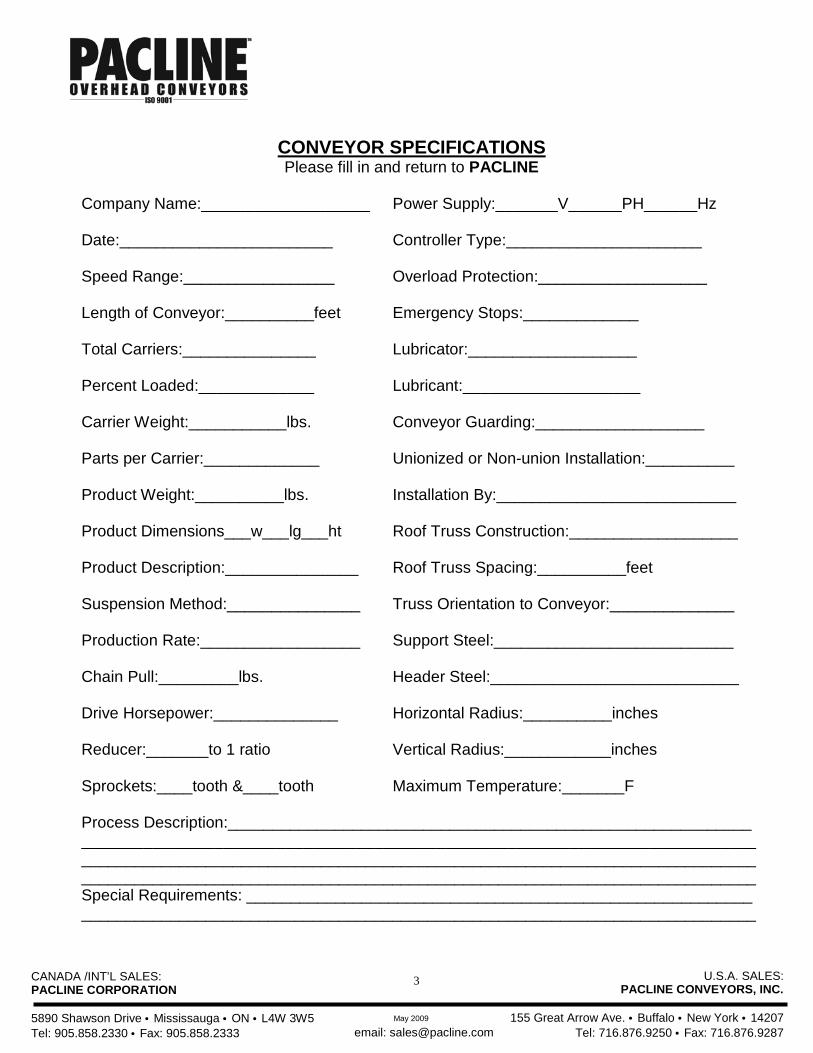
CONVEYOR SPECIFICATIONS Please fill in and return to PACLINE
Company Name:___________________ Power Supply:_______V______PH______Hz Date:________________________ Controller Type:______________________ Speed Range:_________________ Overload Protection:___________________ Length of Conveyor:__________feet Emergency Stops:_____________ Total Carriers:_______________ Lubricator:___________________ Percent Loaded:_____________ Lubricant:____________________ Carrier Weight:___________lbs. Conveyor Guarding:___________________ Parts per Carrier:_____________ Unionized or Non-union Installation:__________ Product Weight:__________lbs. Installation By:___________________________ Product Dimensions___w___lg___ht Roof Truss Construction:___________________ Product Description:_______________ Roof Truss Spacing:__________feet Suspension Method:_______________ Truss Orientation to Conveyor:______________ Production Rate:__________________ Support Steel:___________________________ Chain Pull:_________lbs. Header Steel:____________________________ Drive Horsepower:______________ Horizontal Radius:__________inches Reducer:_______to 1 ratio Vertical Radius:____________inches Sprockets:____tooth &____tooth Maximum Temperature:_______F Process Description:___________________________________________________________ ____________________________________________________________________________ ____________________________________________________________________________ ____________________________________________________________________________ Special Requirements: _________________________________________________________ ____________________________________________________________________________
CANADA /INT’L SALES: PACLINE CORPORATION 5890 Shawson Drive • Mississauga • ON • L4W 3W5 Tel: 905.858.2330 • Fax: 905.858.2333
U.S.A. SALES: PACLINE CONVEYORS, INC.
155 Great Arrow Ave. • Buffalo • New York • 14207
Tel: 716.876.9250 • Fax: 716.876.9287 email: [email protected] May 2009
4
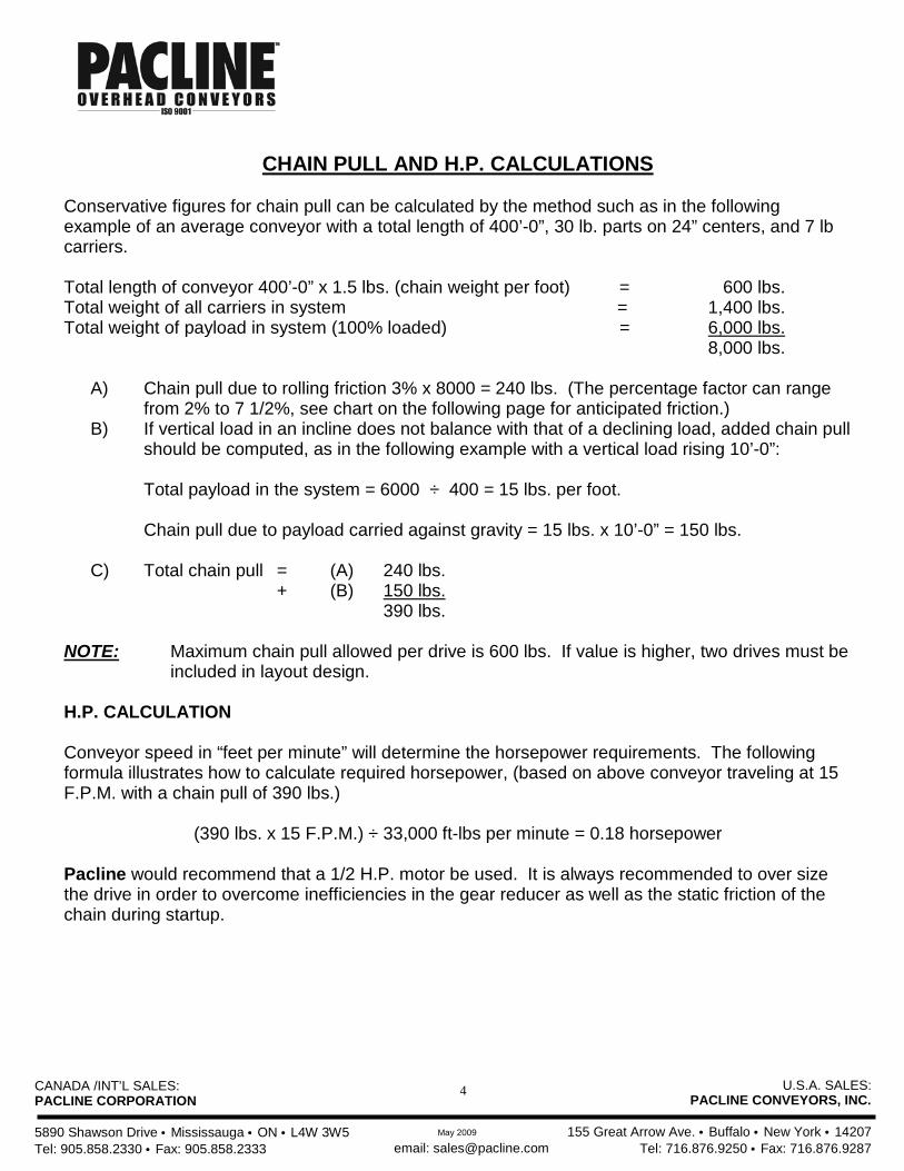
CHAIN PULL AND H.P. CALCULATIONS
Conservative figures for chain pull can be calculated by the method such as in the following example of an average conveyor with a total length of 400’-0”, 30 lb. parts on 24” centers, and 7 lb carriers. Total length of conveyor 400’-0” x 1.5 lbs. (chain weight per foot) = 600 lbs. Total weight of all carriers in system = 1,400 lbs. Total weight of payload in system (100% loaded) = 6,000 lbs. 8,000 lbs.
A) Chain pull due to rolling friction 3% x 8000 = 240 lbs. (The percentage factor can range from 2% to 7 1/2%, see chart on the following page for anticipated friction.)
B) If vertical load in an incline does not balance with that of a declining load, added chain pull should be computed, as in the following example with a vertical load rising 10’-0”:
Total payload in the system = 6000 ÷ 400 = 15 lbs. per foot.
Chain pull due to payload carried against gravity = 15 lbs. x 10’-0” = 150 lbs.
C) Total chain pull = (A) 240 lbs.
+ (B) 150 lbs. 390 lbs. NOTE: Maximum chain pull allowed per drive is 600 lbs. If value is higher, two drives must be
included in layout design. H.P. CALCULATION Conveyor speed in “feet per minute” will determine the horsepower requirements. The following formula illustrates how to calculate required horsepower, (based on above conveyor traveling at 15 F.P.M. with a chain pull of 390 lbs.)
(390 lbs. x 15 F.P.M.) ÷ 33,000 ft-lbs per minute = 0.18 horsepower Pacline would recommend that a 1/2 H.P. motor be used. It is always recommended to over size the drive in order to overcome inefficiencies in the gear reducer as well as the static friction of the chain during startup.
CANADA /INT’L SALES: PACLINE CORPORATION 5890 Shawson Drive • Mississauga • ON • L4W 3W5 Tel: 905.858.2330 • Fax: 905.858.2333
U.S.A. SALES: PACLINE CONVEYORS, INC.
155 Great Arrow Ave. • Buffalo • New York • 14207
Tel: 716.876.9250 • Fax: 716.876.9287 email: [email protected] May 2009
5
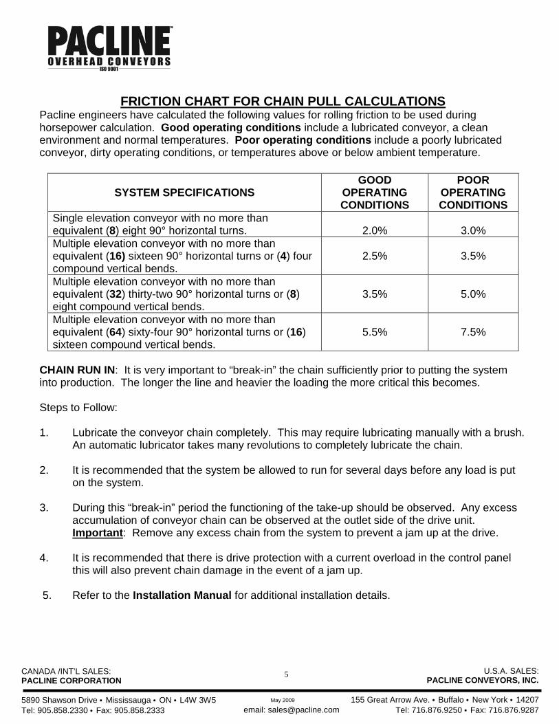
FRICTION CHART FOR CHAIN PULL CALCULATIONS
Pacline engineers have calculated the following values for rolling friction to be used during horsepower calculation. Good operating conditions include a lubricated conveyor, a clean environment and normal temperatures. Poor operating conditions include a poorly lubricated conveyor, dirty operating conditions, or temperatures above or below ambient temperature.
SYSTEM SPECIFICATIONS
GOOD OPERATING CONDITIONS
POOR OPERATING CONDITIONS
Single elevation conveyor with no more than equivalent (8) eight 90° horizontal turns.
2.0%
3.0%
Multiple elevation conveyor with no more than equivalent (16) sixteen 90° horizontal turns or (4) four compound vertical bends.
2.5%
3.5%
Multiple elevation conveyor with no more than equivalent (32) thirty-two 90° horizontal turns or (8) eight compound vertical bends.
3.5%
5.0%
Multiple elevation conveyor with no more than equivalent (64) sixty-four 90° horizontal turns or (16) sixteen compound vertical bends.
5.5%
7.5%
CHAIN RUN IN: It is very important to “break-in” the chain sufficiently prior to putting the system into production. The longer the line and heavier the loading the more critical this becomes. Steps to Follow: 1. Lubricate the conveyor chain completely. This may require lubricating manually with a brush.
An automatic lubricator takes many revolutions to completely lubricate the chain. 2. It is recommended that the system be allowed to run for several days before any load is put
on the system. 3. During this “break-in” period the functioning of the take-up should be observed. Any excess
accumulation of conveyor chain can be observed at the outlet side of the drive unit. Important: Remove any excess chain from the system to prevent a jam up at the drive.
4. It is recommended that there is drive protection with a current overload in the control panel
this will also prevent chain damage in the event of a jam up. 5. Refer to the Installation Manual for additional installation details.
CANADA /INT’L SALES: PACLINE CORPORATION 5890 Shawson Drive • Mississauga • ON • L4W 3W5 Tel: 905.858.2330 • Fax: 905.858.2333
U.S.A. SALES: PACLINE CONVEYORS, INC.
155 Great Arrow Ave. • Buffalo • New York • 14207
Tel: 716.876.9250 • Fax: 716.876.9287 email: [email protected] May 2009
6
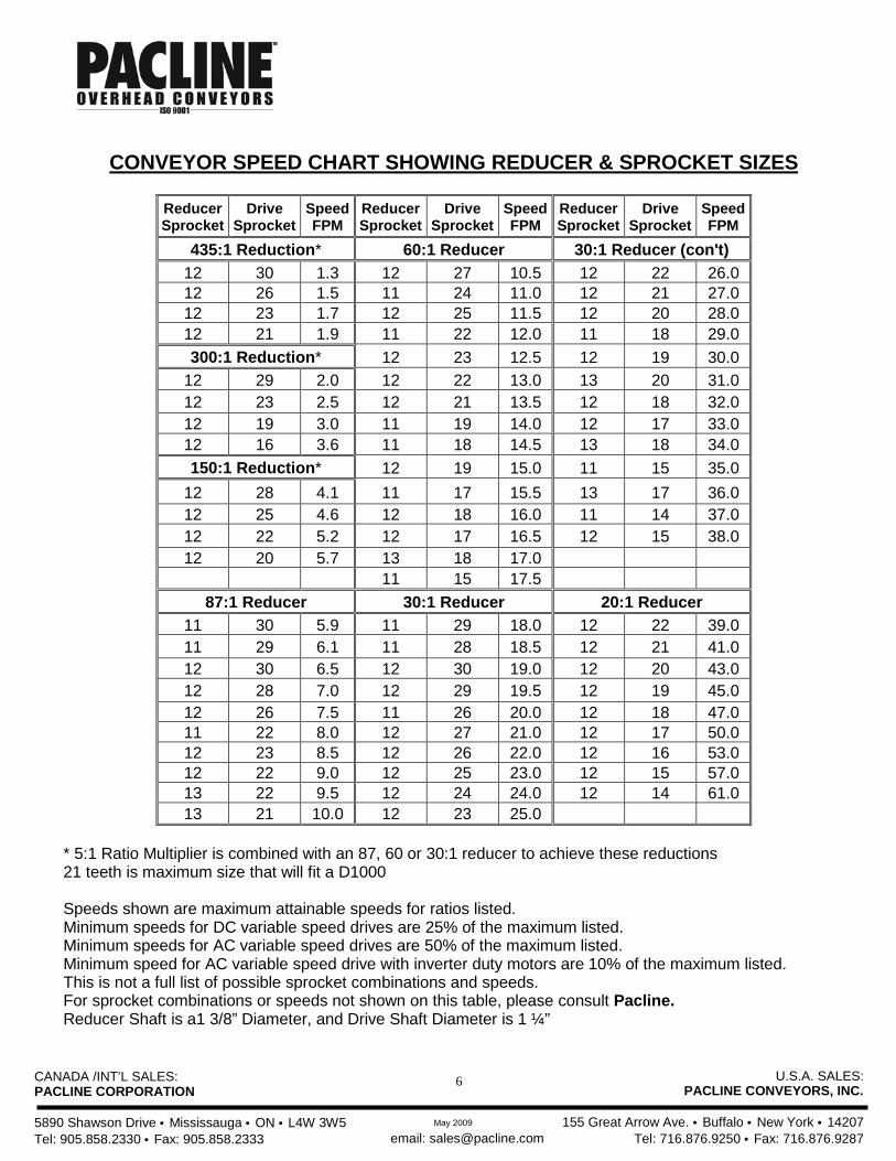
CONVEYOR SPEED CHART SHOWING REDUCER & SPROCKET SIZES
Reducer Sprocket
Drive Sprocket
Speed FPM
Reducer Sprocket
Drive Sprocket
Speed FPM
Reducer Sprocket
Drive Sprocket
Speed FPM
435:1 Reduction* 60:1 Reducer 30:1 Reducer (con't) 12 30 1.3 12 27 10.5 12 22 26.0 12 26 1.5 11 24 11.0 12 21 27.0 12 23 1.7 12 25 11.5 12 20 28.0 12 21 1.9 11 22 12.0 11 18 29.0 300:1 Reduction* 12 23 12.5 12 19 30.0
12 29 2.0 12 22 13.0 13 20 31.0 12 23 2.5 12 21 13.5 12 18 32.0 12 19 3.0 11 19 14.0 12 17 33.0 12 16 3.6 11 18 14.5 13 18 34.0 150:1 Reduction* 12 19 15.0 11 15 35.0
12 28 4.1 11 17 15.5 13 17 36.0 12 25 4.6 12 18 16.0 11 14 37.0 12 22 5.2 12 17 16.5 12 15 38.0 12 20 5.7 13 18 17.0 11 15 17.5
87:1 Reducer 30:1 Reducer 20:1 Reducer 11 30 5.9 11 29 18.0 12 22 39.0 11 29 6.1 11 28 18.5 12 21 41.0 12 30 6.5 12 30 19.0 12 20 43.0 12 28 7.0 12 29 19.5 12 19 45.0 12 26 7.5 11 26 20.0 12 18 47.0 11 22 8.0 12 27 21.0 12 17 50.0 12 23 8.5 12 26 22.0 12 16 53.0 12 22 9.0 12 25 23.0 12 15 57.0 13 22 9.5 12 24 24.0 12 14 61.0 13 21 10.0 12 23 25.0
* 5:1 Ratio Multiplier is combined with an 87, 60 or 30:1 reducer to achieve these reductions 21 teeth is maximum size that will fit a D1000 Speeds shown are maximum attainable speeds for ratios listed. Minimum speeds for DC variable speed drives are 25% of the maximum listed. Minimum speeds for AC variable speed drives are 50% of the maximum listed. Minimum speed for AC variable speed drive with inverter duty motors are 10% of the maximum listed. This is not a full list of possible sprocket combinations and speeds. For sprocket combinations or speeds not shown on this table, please consult Pacline. Reducer Shaft is a1 3/8” Diameter, and Drive Shaft Diameter is 1 ¼”
CANADA /INT’L SALES: PACLINE CORPORATION 5890 Shawson Drive • Mississauga • ON • L4W 3W5 Tel: 905.858.2330 • Fax: 905.858.2333
U.S.A. SALES: PACLINE CONVEYORS, INC.
155 Great Arrow Ave. • Buffalo • New York • 14207
Tel: 716.876.9250 • Fax: 716.876.9287 email: [email protected] May 2009
7
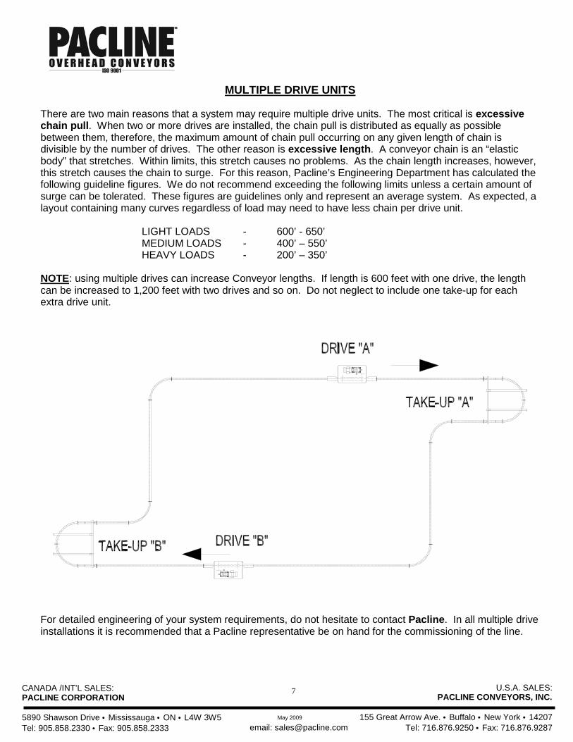
MULTIPLE DRIVE UNITS There are two main reasons that a system may require multiple drive units. The most critical is excessive chain pull. When two or more drives are installed, the chain pull is distributed as equally as possible between them, therefore, the maximum amount of chain pull occurring on any given length of chain is divisible by the number of drives. The other reason is excessive length. A conveyor chain is an “elastic body” that stretches. Within limits, this stretch causes no problems. As the chain length increases, however, this stretch causes the chain to surge. For this reason, Pacline’s Engineering Department has calculated the following guideline figures. We do not recommend exceeding the following limits unless a certain amount of surge can be tolerated. These figures are guidelines only and represent an average system. As expected, a layout containing many curves regardless of load may need to have less chain per drive unit.
LIGHT LOADS - 600’ - 650’ MEDIUM LOADS - 400’ – 550’ HEAVY LOADS - 200’ – 350’
NOTE: using multiple drives can increase Conveyor lengths. If length is 600 feet with one drive, the length can be increased to 1,200 feet with two drives and so on. Do not neglect to include one take-up for each extra drive unit.
For detailed engineering of your system requirements, do not hesitate to contact Pacline. In all multiple drive installations it is recommended that a Pacline representative be on hand for the commissioning of the line.

CANADA /INT’L SALES: PACLINE CORPORATION 5890 Shawson Drive • Mississauga • ON • L4W 3W5 Tel: 905.858.2330 • Fax: 905.858.2333
U.S.A. SALES: PACLINE CONVEYORS, INC.
155 Great Arrow Ave. • Buffalo • New York • 14207
Tel: 716.876.9250 • Fax: 716.876.9287 email: [email protected] May 2009
8
PACLINE L-275, L-375 & L-475 BRUSH LUBRICATOR
These lubricators are designed to be a dependable and economical method of applying the necessary amount of lubricant to the conveyor chain. ADVANTAGES
• Simple and economical • Safe operation • Long lasting • Low maintenance • Clean and effective
SPECIFICATIONS MOUNTING: Can be bolted easily to any standard track inspection port. POWER: L-275: not required L-375: 115 or 230 VAC 50/60 Hz L-475: 115 or 230 VAC 50/60 Hz WARRANTY: One year DELIVERY: Stock OPERATION The L-275 Brush Lubricator, comes complete with a long life, stainless steel brush which applies lubricant to the chain quietly and efficiently. The flow is metered by a needle valve and monitored through a sight glass. A transparent reservoir allows a visual check of the oil supply at all times. The L-375 model has the extra feature of a control solenoid, which opens and closes the oiler valve as required. The solenoid may be wired simply to a switch or timer for control. The L-475 model is available with Nylon or Stainless Steel brushes and comes with a total of 3 brushes. This design ensures quicker and a more even coverage of the conveyor chain. A 1-gallon reservoir extends the period between refills. An integrated control panel with a photo sensor and a programmable timer ensures accurate lubrication intervals on the L-475 oiler. Note: Because each system differs in length/speed/loads/temps etc, the amount of lubrication must be determined through trial and error. See Pacline Drawings No. 123, 123A & 123B.
CANADA /INT’L SALES: PACLINE CORPORATION 5890 Shawson Drive • Mississauga • ON • L4W 3W5 Tel: 905.858.2330 • Fax: 905.858.2333
U.S.A. SALES: PACLINE CONVEYORS, INC.
155 Great Arrow Ave. • Buffalo • New York • 14207
Tel: 716.876.9250 • Fax: 716.876.9287 email: [email protected] May 2009
9
PACLINE L-565 SHOT LUBRICATOR
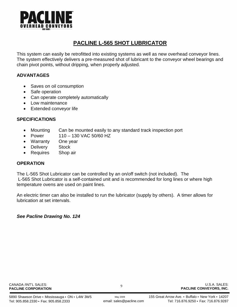
This system can easily be retrofitted into existing systems as well as new overhead conveyor lines. The system effectively delivers a pre-measured shot of lubricant to the conveyor wheel bearings and chain pivot points, without dripping, when properly adjusted. ADVANTAGES
• Saves on oil consumption • Safe operation • Can operate completely automatically • Low maintenance • Extended conveyor life
SPECIFICATIONS
• Mounting Can be mounted easily to any standard track inspection port • Power 110 – 130 VAC 50/60 HZ • Warranty One year • Delivery Stock • Requires Shop air
OPERATION The L-565 Shot Lubricator can be controlled by an on/off switch (not included). The L-565 Shot Lubricator is a self-contained unit and is recommended for long lines or where high temperature ovens are used on paint lines. An electric timer can also be installed to run the lubricator (supply by others). A timer allows for lubrication at set intervals. See Pacline Drawing No. 124
CANADA /INT’L SALES: PACLINE CORPORATION 5890 Shawson Drive • Mississauga • ON • L4W 3W5 Tel: 905.858.2330 • Fax: 905.858.2333
U.S.A. SALES: PACLINE CONVEYORS, INC.
155 Great Arrow Ave. • Buffalo • New York • 14207
Tel: 716.876.9250 • Fax: 716.876.9287 email: [email protected] May 2009
10
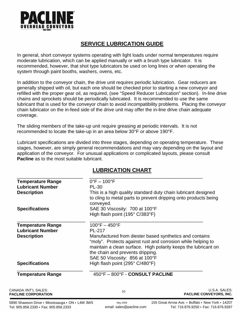
SERVICE LUBRICATION GUIDE
In general, short conveyor systems operating with light loads under normal temperatures require moderate lubrication, which can be applied manually or with a brush type lubricator. It is recommended, however, that shot type lubricators be used on long lines or when operating the system through paint booths, washers, ovens, etc. In addition to the conveyor chain, the drive unit requires periodic lubrication. Gear reducers are generally shipped with oil, but each one should be checked prior to starting a new conveyor and refilled with the proper gear oil, as required, (see “Speed Reducer Lubrication” section). In-line drive chains and sprockets should be periodically lubricated. It is recommended to use the same lubricant that is used for the conveyor chain to avoid incompatibility problems. Placing the conveyor chain lubricator on the in-feed side of the drive unit may offer the in-line drive chain adequate coverage. The sliding members of the take-up unit require greasing at periodic intervals. It is not recommended to locate the take-up in an area below 30°F or above 190°F. Lubricant specifications are divided into three stages, depending on operating temperature. These stages, however, are simply general recommendations and may vary depending on the layout and application of the conveyor. For unusual applications or complicated layouts, please consult Pacline as to the most suitable lubricant.
LUBRICATION CHART _________________________ ___________________________________________ Temperature Range Lubricant Number Description Specifications
0°F – 100°F PL-30 This is a high quality standard duty chain lubricant designed to cling to metal parts to prevent dripping onto products being conveyed. SAE 30 Viscosity: 700 at 100°F High flash point (195° C/383°F)
__________________________ Temperature Range Lubricant Number Description Specifications
___________________________________________ 100°F – 450°F PL-217 Manufactured from diester based synthetics and contains “moly”. Protects against rust and corrosion while helping to maintain a clean surface. High polarity keeps the lubricant on the chain and prevents dripping. SAE 50 Viscosity: 856 at 100°F High flash point (295° C/480°F)
_________________________ ___________________________________________ Temperature Range 450°F – 800°F - CONSULT PACLINE
CANADA /INT’L SALES: PACLINE CORPORATION 5890 Shawson Drive • Mississauga • ON • L4W 3W5 Tel: 905.858.2330 • Fax: 905.858.2333
U.S.A. SALES: PACLINE CONVEYORS, INC.
155 Great Arrow Ave. • Buffalo • New York • 14207
Tel: 716.876.9250 • Fax: 716.876.9287 email: [email protected] May 2009
11
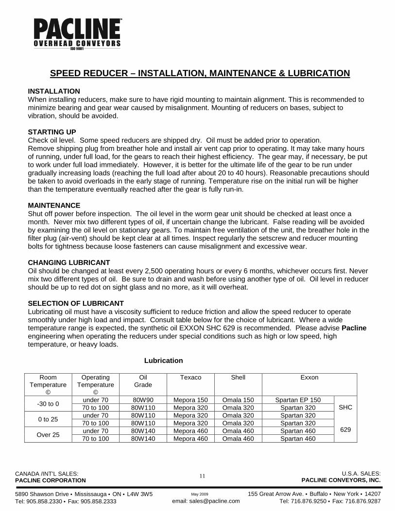
SPEED REDUCER – INSTALLATION, MAINTENANCE & LUBRICATION
INSTALLATION When installing reducers, make sure to have rigid mounting to maintain alignment. This is recommended to minimize bearing and gear wear caused by misalignment. Mounting of reducers on bases, subject to vibration, should be avoided. STARTING UP Check oil level. Some speed reducers are shipped dry. Oil must be added prior to operation. Remove shipping plug from breather hole and install air vent cap prior to operating. It may take many hours of running, under full load, for the gears to reach their highest efficiency. The gear may, if necessary, be put to work under full load immediately. However, it is better for the ultimate life of the gear to be run under gradually increasing loads (reaching the full load after about 20 to 40 hours). Reasonable precautions should be taken to avoid overloads in the early stage of running. Temperature rise on the initial run will be higher than the temperature eventually reached after the gear is fully run-in. MAINTENANCE Shut off power before inspection. The oil level in the worm gear unit should be checked at least once a month. Never mix two different types of oil, if uncertain change the lubricant. False reading will be avoided by examining the oil level on stationary gears. To maintain free ventilation of the unit, the breather hole in the filter plug (air-vent) should be kept clear at all times. Inspect regularly the setscrew and reducer mounting bolts for tightness because loose fasteners can cause misalignment and excessive wear. CHANGING LUBRICANT Oil should be changed at least every 2,500 operating hours or every 6 months, whichever occurs first. Never mix two different types of oil. Be sure to drain and wash before using another type of oil. Oil level in reducer should be up to red dot on sight glass and no more, as it will overheat. SELECTION OF LUBRICANT Lubricating oil must have a viscosity sufficient to reduce friction and allow the speed reducer to operate smoothly under high load and impact. Consult table below for the choice of lubricant. Where a wide temperature range is expected, the synthetic oil EXXON SHC 629 is recommended. Please advise Pacline engineering when operating the reducers under special conditions such as high or low speed, high temperature, or heavy loads. Lubrication
Room Temperature
©
Operating Temperature
©
Oil Grade
Texaco Shell Exxon
-30 to 0 under 70 80W90 Mepora 150 Omala 150 Spartan EP 150 SHC
629
70 to 100 80W110 Mepora 320 Omala 320 Spartan 320
0 to 25 under 70 80W110 Mepora 320 Omala 320 Spartan 320 70 to 100 80W110 Mepora 320 Omala 320 Spartan 320
Over 25 under 70 80W140 Mepora 460 Omala 460 Spartan 460 70 to 100 80W140 Mepora 460 Omala 460 Spartan 460
CANADA /INT’L SALES: PACLINE CORPORATION 5890 Shawson Drive • Mississauga • ON • L4W 3W5 Tel: 905.858.2330 • Fax: 905.858.2333
U.S.A. SALES: PACLINE CONVEYORS, INC.
155 Great Arrow Ave. • Buffalo • New York • 14207
Tel: 716.876.9250 • Fax: 716.876.9287 email: [email protected] May 2009
12
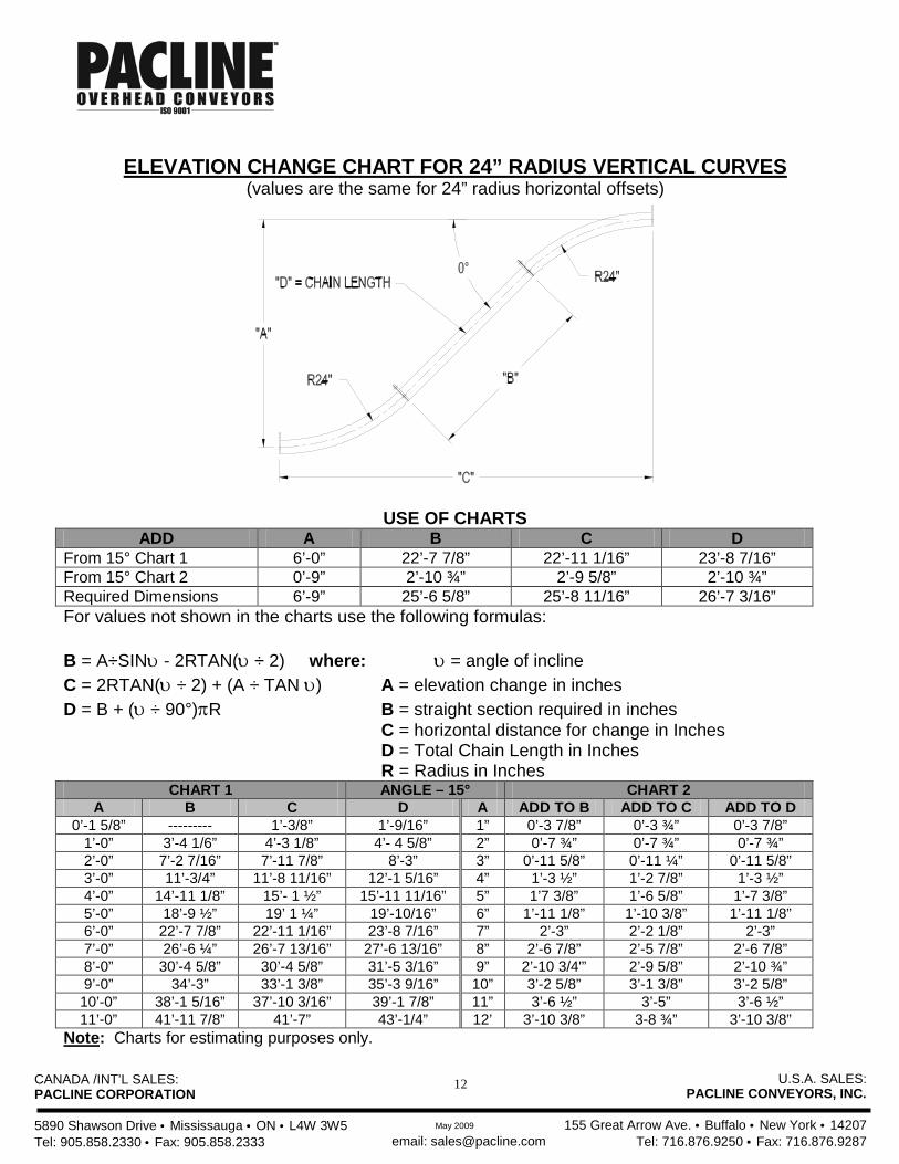
ELEVATION CHANGE CHART FOR 24” RADIUS VERTICAL CURVES
(values are the same for 24” radius horizontal offsets)
USE OF CHARTS ADD A B C D
From 15° Chart 1 6’-0” 22’-7 7/8” 22’-11 1/16” 23’-8 7/16” From 15° Chart 2 0’-9” 2’-10 ¾” 2’-9 5/8” 2’-10 ¾” Required Dimensions 6’-9” 25’-6 5/8” 25’-8 11/16” 26’-7 3/16” For values not shown in the charts use the following formulas: B = A÷SINυ - 2RTAN(υ ÷ 2) where: υ = angle of incline C = 2RTAN(υ ÷ 2) + (A ÷ TAN υ) A = elevation change in inches D = B + (υ ÷ 90°)πR B = straight section required in inches C = horizontal distance for change in Inches D = Total Chain Length in Inches R = Radius in Inches
CHART 1 ANGLE – 15° CHART 2 A B C D A ADD TO B ADD TO C ADD TO D
0’-1 5/8” --------- 1’-3/8” 1’-9/16” 1” 0’-3 7/8” 0’-3 ¾” 0’-3 7/8” 1’-0” 3’-4 1/6” 4’-3 1/8” 4’- 4 5/8” 2” 0’-7 ¾” 0’-7 ¾” 0’-7 ¾” 2’-0” 7’-2 7/16” 7’-11 7/8” 8’-3” 3” 0’-11 5/8” 0’-11 ¼” 0’-11 5/8” 3’-0” 11’-3/4” 11’-8 11/16” 12’-1 5/16” 4” 1’-3 ½” 1’-2 7/8” 1’-3 ½” 4’-0” 14’-11 1/8” 15’- 1 ½” 15’-11 11/16” 5” 1’7 3/8” 1’-6 5/8” 1’-7 3/8” 5’-0” 18’-9 ½” 19’ 1 ¼” 19’-10/16” 6” 1’-11 1/8” 1’-10 3/8” 1’-11 1/8” 6’-0” 22’-7 7/8” 22’-11 1/16” 23’-8 7/16” 7” 2’-3” 2’-2 1/8” 2’-3” 7’-0” 26’-6 ¼” 26’-7 13/16” 27’-6 13/16” 8” 2’-6 7/8” 2’-5 7/8” 2’-6 7/8” 8’-0” 30’-4 5/8” 30’-4 5/8” 31’-5 3/16” 9” 2’-10 3/4'” 2’-9 5/8” 2’-10 ¾” 9’-0” 34’-3” 33’-1 3/8” 35’-3 9/16” 10” 3’-2 5/8” 3’-1 3/8” 3’-2 5/8” 10’-0” 38’-1 5/16” 37’-10 3/16” 39’-1 7/8” 11” 3’-6 ½” 3’-5” 3’-6 ½” 11’-0” 41’-11 7/8” 41’-7” 43’-1/4” 12’ 3’-10 3/8” 3-8 ¾” 3’-10 3/8”
Note: Charts for estimating purposes only.
CANADA /INT’L SALES: PACLINE CORPORATION 5890 Shawson Drive • Mississauga • ON • L4W 3W5 Tel: 905.858.2330 • Fax: 905.858.2333
U.S.A. SALES: PACLINE CONVEYORS, INC.
155 Great Arrow Ave. • Buffalo • New York • 14207
Tel: 716.876.9250 • Fax: 716.876.9287 email: [email protected] May 2009
13
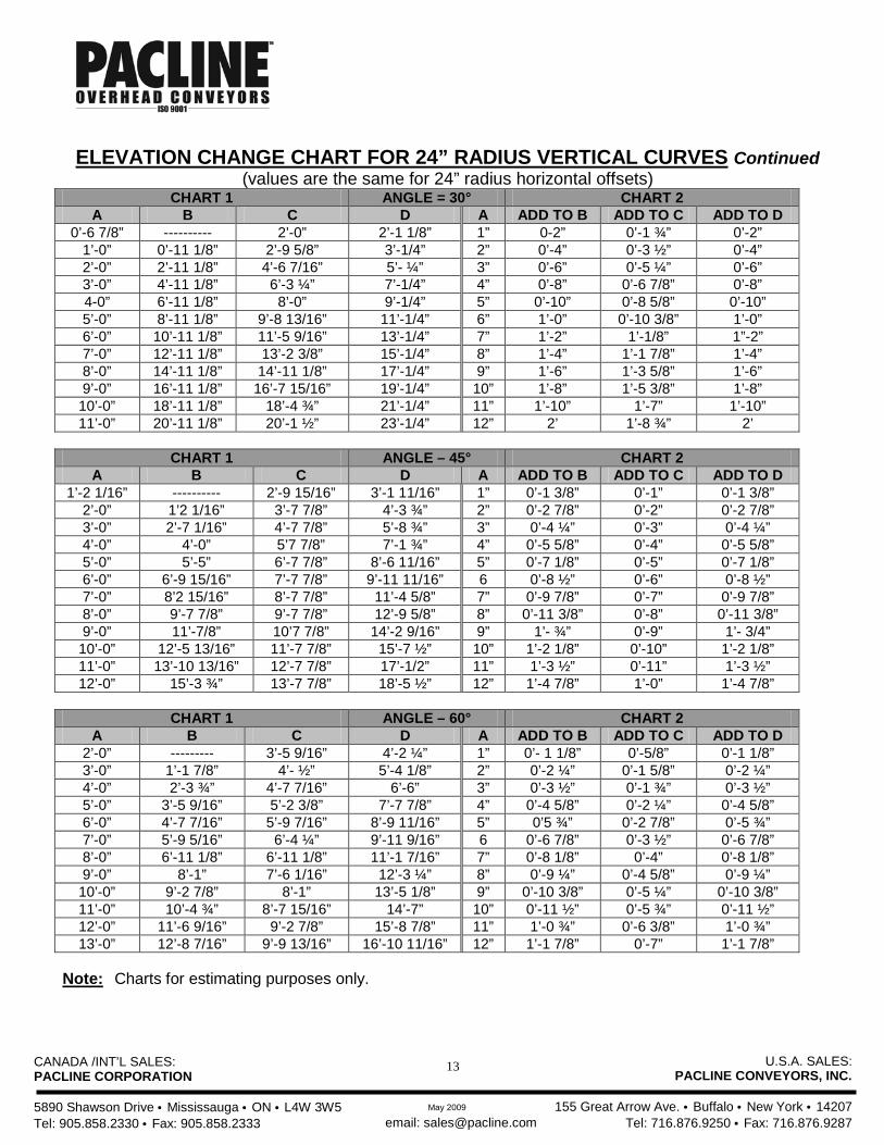
ELEVATION CHANGE CHART FOR 24” RADIUS VERTICAL CURVES Continued
(values are the same for 24” radius horizontal offsets) CHART 1 ANGLE = 30° CHART 2
A B C D A ADD TO B ADD TO C ADD TO D 0’-6 7/8” ---------- 2’-0” 2’-1 1/8” 1” 0-2” 0’-1 ¾” 0’-2”
1’-0” 0’-11 1/8” 2’-9 5/8” 3’-1/4” 2” 0’-4” 0’-3 ½” 0’-4” 2’-0” 2’-11 1/8” 4’-6 7/16” 5’- ¼” 3” 0’-6” 0’-5 ¼” 0’-6” 3’-0” 4’-11 1/8” 6’-3 ¼” 7’-1/4” 4” 0’-8” 0’-6 7/8” 0’-8” 4-0” 6’-11 1/8” 8’-0” 9’-1/4” 5” 0’-10” 0’-8 5/8” 0’-10” 5’-0” 8’-11 1/8” 9’-8 13/16” 11’-1/4” 6” 1’-0” 0’-10 3/8” 1’-0” 6’-0” 10’-11 1/8” 11’-5 9/16” 13’-1/4” 7” 1’-2” 1’-1/8” 1”-2” 7’-0” 12’-11 1/8” 13’-2 3/8” 15’-1/4” 8” 1’-4” 1’-1 7/8” 1’-4” 8’-0” 14’-11 1/8” 14’-11 1/8” 17’-1/4” 9” 1’-6” 1’-3 5/8” 1’-6” 9’-0” 16’-11 1/8” 16’-7 15/16” 19’-1/4” 10” 1’-8” 1’-5 3/8” 1’-8” 10’-0” 18’-11 1/8” 18’-4 ¾” 21’-1/4” 11” 1’-10” 1’-7” 1’-10” 11’-0” 20’-11 1/8” 20’-1 ½” 23’-1/4” 12” 2’ 1’-8 ¾” 2’
CHART 1 ANGLE – 45° CHART 2
A B C D A ADD TO B ADD TO C ADD TO D 1’-2 1/16” ---------- 2’-9 15/16” 3’-1 11/16” 1” 0’-1 3/8” 0’-1” 0’-1 3/8”
2’-0” 1’2 1/16” 3’-7 7/8” 4’-3 ¾” 2” 0’-2 7/8” 0’-2” 0’-2 7/8” 3’-0” 2’-7 1/16” 4’-7 7/8” 5’-8 ¾” 3” 0’-4 ¼” 0’-3” 0’-4 ¼” 4’-0” 4’-0” 5’7 7/8” 7’-1 ¾” 4” 0’-5 5/8” 0’-4” 0’-5 5/8” 5’-0” 5’-5” 6’-7 7/8” 8’-6 11/16” 5” 0’-7 1/8” 0’-5” 0’-7 1/8” 6’-0” 6’-9 15/16” 7’-7 7/8” 9’-11 11/16” 6 0’-8 ½” 0’-6” 0’-8 ½” 7’-0” 8’2 15/16” 8’-7 7/8” 11’-4 5/8” 7” 0’-9 7/8” 0’-7” 0’-9 7/8” 8’-0” 9’-7 7/8” 9’-7 7/8” 12’-9 5/8” 8” 0’-11 3/8” 0’-8” 0’-11 3/8” 9’-0” 11’-7/8” 10’7 7/8” 14’-2 9/16” 9” 1’- ¾” 0’-9” 1’- 3/4” 10’-0” 12’-5 13/16” 11’-7 7/8” 15’-7 ½” 10” 1’-2 1/8” 0’-10” 1’-2 1/8” 11’-0” 13’-10 13/16” 12’-7 7/8” 17’-1/2” 11” 1’-3 ½” 0’-11” 1’-3 ½” 12’-0” 15’-3 ¾” 13’-7 7/8” 18’-5 ½” 12” 1’-4 7/8” 1’-0” 1’-4 7/8”
CHART 1 ANGLE – 60° CHART 2
A B C D A ADD TO B ADD TO C ADD TO D 2’-0” --------- 3’-5 9/16” 4’-2 ¼” 1” 0’- 1 1/8” 0’-5/8” 0’-1 1/8” 3’-0” 1’-1 7/8” 4’- ½” 5’-4 1/8” 2” 0’-2 ¼” 0’-1 5/8” 0’-2 ¼” 4’-0” 2’-3 ¾” 4’-7 7/16” 6’-6” 3” 0’-3 ½” 0’-1 ¾” 0’-3 ½” 5’-0” 3’-5 9/16” 5’-2 3/8” 7’-7 7/8” 4” 0’-4 5/8” 0’-2 ¼” 0’-4 5/8” 6’-0” 4’-7 7/16” 5’-9 7/16” 8’-9 11/16” 5” 0’5 ¾” 0’-2 7/8” 0’-5 ¾” 7’-0” 5’-9 5/16” 6’-4 ¼” 9’-11 9/16” 6 0’-6 7/8” 0’-3 ½” 0’-6 7/8” 8’-0” 6’-11 1/8” 6’-11 1/8” 11’-1 7/16” 7” 0’-8 1/8” 0’-4” 0’-8 1/8” 9’-0” 8’-1” 7’-6 1/16” 12’-3 ¼” 8” 0’-9 ¼” 0’-4 5/8” 0’-9 ¼” 10’-0” 9’-2 7/8” 8’-1” 13’-5 1/8” 9” 0’-10 3/8” 0’-5 ¼” 0’-10 3/8” 11’-0” 10’-4 ¾” 8’-7 15/16” 14’-7” 10” 0’-11 ½” 0’-5 ¾” 0’-11 ½” 12’-0” 11’-6 9/16” 9’-2 7/8” 15’-8 7/8” 11” 1’-0 ¾” 0’-6 3/8” 1’-0 ¾” 13’-0” 12’-8 7/16” 9’-9 13/16” 16’-10 11/16” 12” 1’-1 7/8” 0’-7” 1’-1 7/8”
Note: Charts for estimating purposes only.

CANADA /INT’L SALES: PACLINE CORPORATION 5890 Shawson Drive • Mississauga • ON • L4W 3W5 Tel: 905.858.2330 • Fax: 905.858.2333
U.S.A. SALES: PACLINE CONVEYORS, INC.
155 Great Arrow Ave. • Buffalo • New York • 14207
Tel: 716.876.9250 • Fax: 716.876.9287 email: [email protected] May 2009
14
ELEVATION CHANGE CHART FOR 18” RADIUS VERTICAL CURVES (values are the same for 18” radius horizontal offsets)
USE OF CHARTS
ADD A B C D
From 15° Chart 1 6’-0” 22’-9 7/16” 22’-9 7/16” 23’-6 7/8” From 15° Chart 2 0’-9” 2’-10 ¾” 2’-9 5/8” 2’-10 ¾” Required Dimensions 6’-9” 25’-8 3/16” 25’-7 1/16” 26’-5 5/8” For values not shown in the charts use the following formulas: B = A÷SINυ - 2RTAN(υ ÷ 2) where: υ = angle of incline C = 2RTAN(υ ÷ 2) + (A ÷ TANυ) A = elevation change in inches D = B + (υ ÷ 90°)πR B = straight section required in inches C = horizontal distance for change in Inches D = Total Chain Length in Inches R = Radius in Inches
CHART 1 ANGLE – 15° CHART 2 A B C D A ADD TO B ADD TO C ADD TO D
0’-1 ½” ---------- 0’-9 5/16” 0’-9 3/8” 1” 0’-3 7/8” 0’-3 ¾” 0’-3 7/8” 1’-0” 3’5 5/8” 4’-1 ½” 4’-3 1/16” 2” 0’-7 ¾” 0’-7 ¾” 0’-7 ¾” 2’-0” 7’-4” 7’-10 5/16” 8’-1 7/16” 3” 0’-11 5/8” 0’-11 ¼” 0’-11 5/8” 3’-0” 11’-2 3/8” 11’-7 1/8” 11’-11 13/16” 4” 1’-3 ½” 1’-2 7/8” 1’-3 ½” 4’-0” 15’-3/4” 15’-3 7/8” 15’-10 3/16” 5” 1’-7 3/8” 1’-6 5/8” 1’-7 3/8” 5’-0” 18’-11 1/8” 19’-11/16” 19’-8 9/16” 6” 1’-11 1/8” 1’-10 3/8” 1’-11 1/8” 6’-0” 22’-9 7/16” 22’-9 7/16” 23’-6 7/8” 7” 2’-3” 2’-2 1/8” 2’-3” 7’-0” 26’-7 13/16” 26’-6 ¼” 27’-5 ¼” 8” 2’-6 7/8” 2’-5 7/8” 2’-6 7/8” 8’-0” 30’-6 ¼” 30’-3” 31’-3 11/16” 9” 2’-10 ¾” 2’-9 5/8” 2’-10 ¾” 9’-0” 34’-4 9/16” 33’-11 13/16” 35’-2” 10” 3’-2 5/8” 3’-1 3/8” 3’-2 5/8” 10’-0” 38’-2 7/8” 37’-8 9/16” 39’- 5/16” 11” 3’-6 ½” 3’-5” 3’-6 ½” 11’-0” 42’-1 1/4” 41’-5 3/8” 42’- 10 11/16” 12” 3’-10 3/8” 3’-8 ¾” 3’-10 3/8”
Note: Charts for estimating purposes only.
CANADA /INT’L SALES: PACLINE CORPORATION 5890 Shawson Drive • Mississauga • ON • L4W 3W5 Tel: 905.858.2330 • Fax: 905.858.2333
U.S.A. SALES: PACLINE CONVEYORS, INC.
155 Great Arrow Ave. • Buffalo • New York • 14207
Tel: 716.876.9250 • Fax: 716.876.9287 email: [email protected] May 2009
15
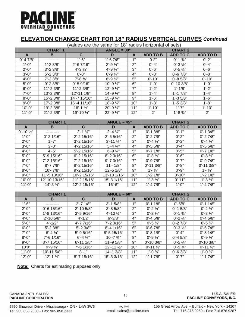
ELEVATION CHANGE CHART FOR 18” RADIUS VERTICAL CURVES Continued (values are the same for 18” radius horizontal offsets)
CHART 1 ANGLE = 30° CHART 2 A B C D A ADD TO B ADD TO C ADD TO D
0’-4 7/8” ---------- 1’-6” 1’-6 7/8” 1” 0-2” 0’-1 ¾” 0’-2” 1’-0” 1’-2 3/8” 2’-6 7/16” 2’-9 ¼” 2” 0’-4” 0’-3 ½” 0’-4” 2’-0” 3’-2 3/8” 4’-3 ¼” 4’-9 ¼” 3” 0’-6” 0’-5 ¼” 0’-6” 3’-0” 5’-2 3/8” 6’-0” 6’-9 ¼” 4” 0’-8” 0’-6 7/8” 0’-8” 4’-0” 7’-2 3/8” 7’-8 ¾” 8’-9 ¼” 5” 0’-10” 0’-8 5/8” 0’-10” 5’-0” 9’-2 3/8” 9’-5 9/16” 10’-9 ¼” 6” 1’-0” 0’-10 3/8” 1’-0” 6’-0” 11’-2 3/8” 11’-2 3/8” 12’-9 ¼” 7” 1’-2” 1’-1/8” 1’-2” 7’-0” 13’-2 3/8” 12’-11 1/8” 14’-9 ¼” 8” 1’-4” 1’-1 7/8” 1’-4” 8’-0” 15’-2 3/8” 14’-7 15/16” 15’-9 ¼” 9” 1’-6” 1’-3 5/8” 1’-6” 9’-0” 17’-2 3/8” 16’-4 11/16” 18’-9 ¼” 10” 1’-8” 1’-5 3/8” 1’-8” 10’-0” 19’-2 3/8” 18’-1 ½” 20’-9 ¼” 11” 1’-10” 1’-7” 1’-10” 11’-0” 21’-2 3/8” 19’-10 ¼” 22’-9 ¼” 12” 2’ 1’-8 ¾” 2’
CHART 1 ANGLE – 45° CHART 2
A B C D A ADD TO B ADD TO C ADD TO D 0’-10 ½” ---------- 2’-1 ½” 2’-4 ¼” 1” 0’-1 3/8” 0’-1” 0’-1 3/8”
1’-0” 0’-2 1/16” 2’-2 15/16” 2’-6 5/16” 2” 0’-2 7/8” 0’-2” 0’-2 7/8” 2’-0” 1’-7” 3’-2 15/16” 3’-11 ¼” 3” 0’-4 ¼” 0’-3” 0’-4 ¼” 3’-0” 3’-0” 4’-2 15/16” 5’-4 ¼” 4” 0’-5 5/8” 0’-4” 0’-5 5/8” 4’-0” 4’-5” 5’-2 15/16” 6’-9 ¼” 5” 0’-7 1/8” 0’-5” 0’-7 1/8” 5’-0” 5’-9 15/16” 6’-2 15/16” 8’-2 3/16” 6” 0’-8 ½” 0’-6” 0’-8 ½” 6’-0” 7’-2 15/16” 7’-2 15/16” 9’-7 3/16” 7” 0’-9 7/8” 0’-7” 0’-9 7/8” 7’-0” 8’-7 7/8” 8’-2 15/16” 11’- 1/8” 8” 0’-11 3/8” 0’-8” 0’-11 3/8” 8’-0” 10’- 7/8” 9’-2 15/16” 12’-5 1/8” 9” 1’- ¾” 0’-9” 1’- ¾” 9’-0” 11’-5 13/16” 10’-2 15/16” 13’-10 1/16” 10” 1’-2 1/8” 0’-10” 1’-2 1/8” 10’-0” 12’-10 13/16” 11’-2 15/16” 15’-3 1/16” 11” 1’-3 ½” 0’-11” 1’-3 ½” 11’-0” 14’-3 ¾” 12’-2 15/16” 16’-6” 12” 1’-4 7/8” 1’-0” 1’-4 7/8”
CHART 1 ANGLE – 60° CHART 2
A B C D A ADD TO B ADD TO C ADD TO D 1’-6” ---------- 2’-7 1/8” 3’-1 5/8” 1” 0’-1 1/8” 0’-5/8” 0’-1 1/8” 2’-0” 0’-6 15/16” 2’-10 5/8” 3’-8 5/8” 2” 0’-2 ¼” 0’-1 5/8” 0’-2 ¼” 3’-0” 1’-8 13/16” 3’-5 9/16” 4’-10 ½” 3” 0’-3 ½” 0’-1 ¾” 0’-3 ½” 4’-0” 2’-10 5/8” 4’-1/2” 6’-3/8” 4” 0’-4 5/8” 0’-2 ¼” 0’-4 5/8” 5’-0” 4’-1/2” 4’-7 7/16” 7’-2 3/16” 5” 0’-5 ¾” 0’-2 7/8” 0’-5 ¾” 6’-0” 5’-2 3/8” 5’-2 3/8” 8’-4 1/16” 6” 0’-6 7/8” 0’-3 ½” 0’-6 7/8” 7’-0” 6’-4 ¼” 5’-9 5/16” 9’-5 15/16” 7” 0’-8 1/8” 0’-4” 0’-8 1/8” 8’-0” 7’-6 1/16” 6’-4 ¼” 10’-7 ¾” 8” 0’-9 ¼” 0’-4 5/8” 0’-9 ¼” 9’-0” 8’-7 15/16” 6’-11 1/8” 11’-9 5/8” 9” 0’-10 3/8” 0’-5 ¼” 0’-10 3/8” 10’0” 9’-9 ¾” 7’-6 1/16” 12’-11 ½” 10” 0’-11 ½” 0’-5 ¾” 0’-11 ½” 11’-0” 10’-11 5/8” 8’-1” 14’-1 3/8” 11” 1’-0 ¾” 0’-6 3/8” 1’-0 ¾” 12’-0” 12’-1 ½” 8’-7 15/16” 15’-3 3/16” 12” 1’-1 7/8” 0’-7” 1’-1 7/8”
Note: Charts for estimating purposes only.
CANADA /INT’L SALES: PACLINE CORPORATION 5890 Shawson Drive • Mississauga • ON • L4W 3W5 Tel: 905.858.2330 • Fax: 905.858.2333
U.S.A. SALES: PACLINE CONVEYORS, INC.
155 Great Arrow Ave. • Buffalo • New York • 14207
Tel: 716.876.9250 • Fax: 716.876.9287 email: [email protected] May 2009
16
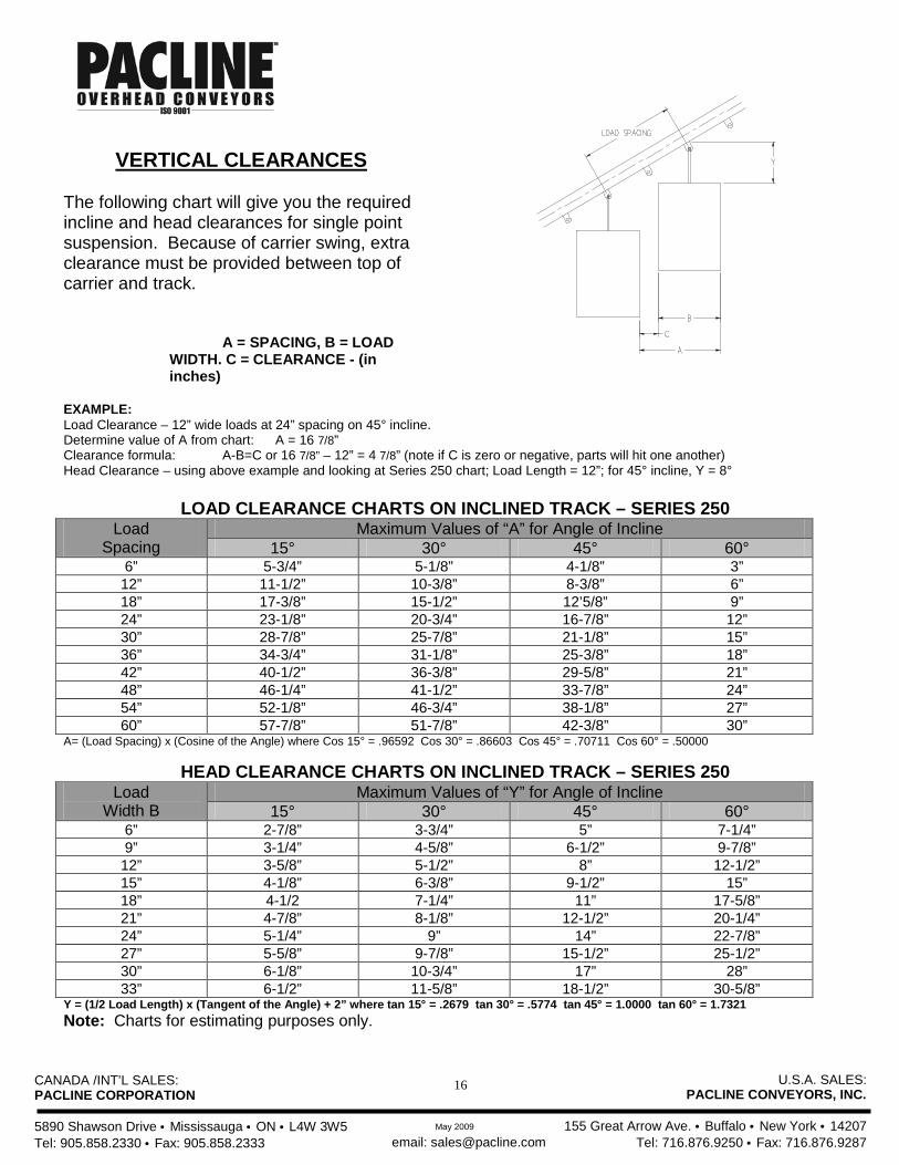
VERTICAL CLEARANCES
The following chart will give you the required incline and head clearances for single point suspension. Because of carrier swing, extra clearance must be provided between top of carrier and track.
A = SPACING, B = LOAD WIDTH. C = CLEARANCE - (in inches)
EXAMPLE: Load Clearance – 12” wide loads at 24” spacing on 45° incline. Determine value of A from chart: A = 16 7/8” Clearance formula: A-B=C or 16 7/8” – 12” = 4 7/8” (note if C is zero or negative, parts will hit one another) Head Clearance – using above example and looking at Series 250 chart; Load Length = 12”; for 45° incline, Y = 8°
LOAD CLEARANCE CHARTS ON INCLINED TRACK – SERIES 250
Load Spacing
Maximum Values of “A” for Angle of Incline 15° 30° 45° 60°
6” 5-3/4” 5-1/8” 4-1/8” 3” 12” 11-1/2” 10-3/8” 8-3/8” 6” 18” 17-3/8” 15-1/2” 12’5/8” 9” 24” 23-1/8” 20-3/4” 16-7/8” 12” 30” 28-7/8” 25-7/8” 21-1/8” 15” 36” 34-3/4” 31-1/8” 25-3/8” 18” 42” 40-1/2” 36-3/8” 29-5/8” 21” 48” 46-1/4” 41-1/2” 33-7/8” 24” 54” 52-1/8” 46-3/4” 38-1/8” 27” 60” 57-7/8” 51-7/8” 42-3/8” 30”
A= (Load Spacing) x (Cosine of the Angle) where Cos 15° = .96592 Cos 30° = .86603 Cos 45° = .70711 Cos 60° = .50000
HEAD CLEARANCE CHARTS ON INCLINED TRACK – SERIES 250 Load
Width B Maximum Values of “Y” for Angle of Incline
15° 30° 45° 60° 6” 2-7/8” 3-3/4” 5” 7-1/4” 9” 3-1/4” 4-5/8” 6-1/2” 9-7/8” 12” 3-5/8” 5-1/2” 8” 12-1/2” 15” 4-1/8” 6-3/8” 9-1/2” 15” 18” 4-1/2 7-1/4” 11” 17-5/8” 21” 4-7/8” 8-1/8” 12-1/2” 20-1/4” 24” 5-1/4” 9” 14” 22-7/8” 27” 5-5/8” 9-7/8” 15-1/2” 25-1/2” 30” 6-1/8” 10-3/4” 17” 28” 33” 6-1/2” 11-5/8” 18-1/2” 30-5/8”
Y = (1/2 Load Length) x (Tangent of the Angle) + 2” where tan 15° = .2679 tan 30° = .5774 tan 45° = 1.0000 tan 60° = 1.7321 Note: Charts for estimating purposes only.
CANADA /INT’L SALES: PACLINE CORPORATION 5890 Shawson Drive • Mississauga • ON • L4W 3W5 Tel: 905.858.2330 • Fax: 905.858.2333
U.S.A. SALES: PACLINE CONVEYORS, INC.
155 Great Arrow Ave. • Buffalo • New York • 14207
Tel: 716.876.9250 • Fax: 716.876.9287 email: [email protected] May 2009
17
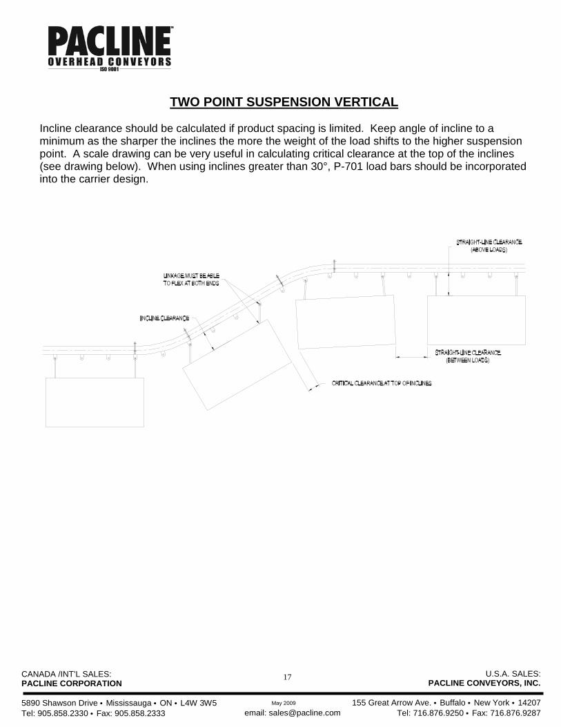
TWO POINT SUSPENSION VERTICAL
Incline clearance should be calculated if product spacing is limited. Keep angle of incline to a minimum as the sharper the inclines the more the weight of the load shifts to the higher suspension point. A scale drawing can be very useful in calculating critical clearance at the top of the inclines (see drawing below). When using inclines greater than 30°, P-701 load bars should be incorporated into the carrier design.
CANADA /INT’L SALES: PACLINE CORPORATION 5890 Shawson Drive • Mississauga • ON • L4W 3W5 Tel: 905.858.2330 • Fax: 905.858.2333
U.S.A. SALES: PACLINE CONVEYORS, INC.
155 Great Arrow Ave. • Buffalo • New York • 14207
Tel: 716.876.9250 • Fax: 716.876.9287 email: [email protected] May 2009
18
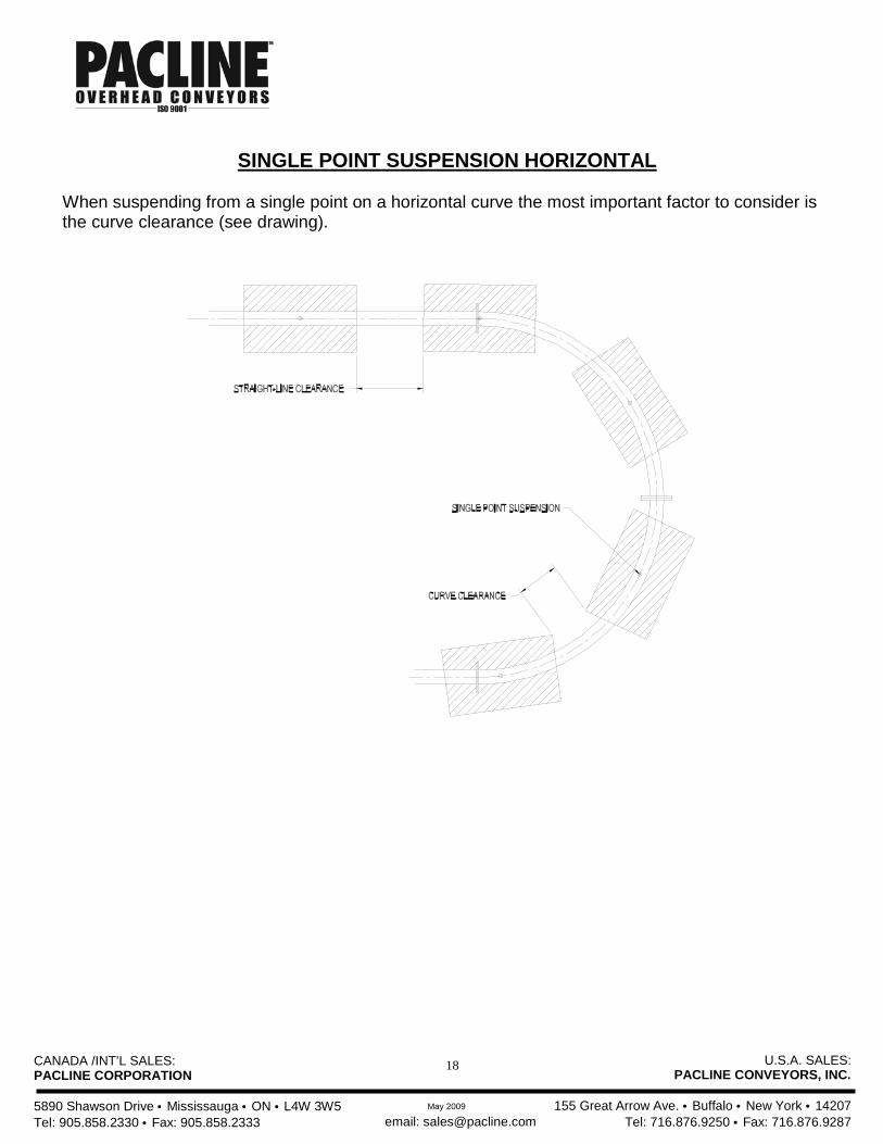
SINGLE POINT SUSPENSION HORIZONTAL
When suspending from a single point on a horizontal curve the most important factor to consider is the curve clearance (see drawing).
CANADA /INT’L SALES: PACLINE CORPORATION 5890 Shawson Drive • Mississauga • ON • L4W 3W5 Tel: 905.858.2330 • Fax: 905.858.2333
U.S.A. SALES: PACLINE CONVEYORS, INC.
155 Great Arrow Ave. • Buffalo • New York • 14207
Tel: 716.876.9250 • Fax: 716.876.9287 email: [email protected] May 2009
19
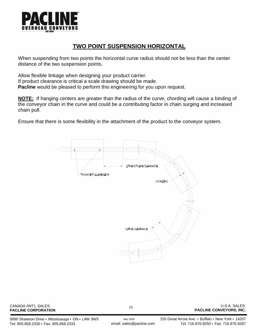
TWO POINT SUSPENSION HORIZONTAL
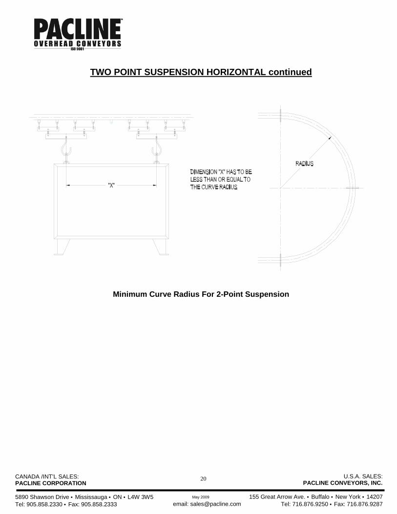
When suspending from two points the horizontal curve radius should not be less than the center distance of the two suspension points. Allow flexible linkage when designing your product carrier. If product clearance is critical a scale drawing should be made. Pacline would be pleased to perform this engineering for you upon request.
NOTE: If hanging centers are greater than the radius of the curve, chording will cause a binding of the conveyor chain in the curve and could be a contributing factor in chain surging and increased chain pull. Ensure that there is some flexibility in the attachment of the product to the conveyor system.
CANADA /INT’L SALES: PACLINE CORPORATION 5890 Shawson Drive • Mississauga • ON • L4W 3W5 Tel: 905.858.2330 • Fax: 905.858.2333
U.S.A. SALES: PACLINE CONVEYORS, INC.
155 Great Arrow Ave. • Buffalo • New York • 14207
Tel: 716.876.9250 • Fax: 716.876.9287 email: [email protected] May 2009
20
TWO POINT SUSPENSION HORIZONTAL continued
Minimum Curve Radius For 2-Point Suspension
CANADA /INT’L SALES: PACLINE CORPORATION 5890 Shawson Drive • Mississauga • ON • L4W 3W5 Tel: 905.858.2330 • Fax: 905.858.2333
U.S.A. SALES: PACLINE CONVEYORS, INC.
155 Great Arrow Ave. • Buffalo • New York • 14207
Tel: 716.876.9250 • Fax: 716.876.9287 email: [email protected] May 2009
21
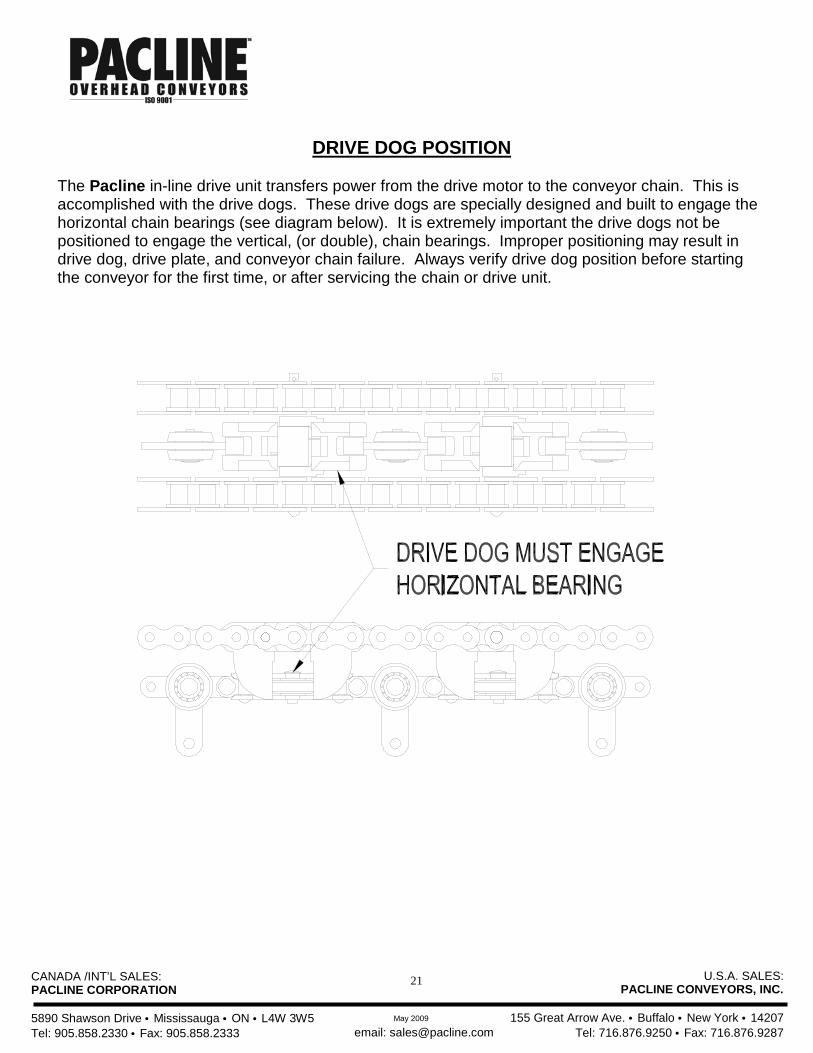
DRIVE DOG POSITION
The Pacline in-line drive unit transfers power from the drive motor to the conveyor chain. This is accomplished with the drive dogs. These drive dogs are specially designed and built to engage the horizontal chain bearings (see diagram below). It is extremely important the drive dogs not be positioned to engage the vertical, (or double), chain bearings. Improper positioning may result in drive dog, drive plate, and conveyor chain failure. Always verify drive dog position before starting the conveyor for the first time, or after servicing the chain or drive unit.

CANADA /INT’L SALES: PACLINE CORPORATION 5890 Shawson Drive • Mississauga • ON • L4W 3W5 Tel: 905.858.2330 • Fax: 905.858.2333
U.S.A. SALES: PACLINE CONVEYORS, INC.
155 Great Arrow Ave. • Buffalo • New York • 14207
Tel: 716.876.9250 • Fax: 716.876.9287 email: [email protected] May 2009
22
WELDING SPECIFICATIONS PACLINE CONVEYOR TRACK
1) Welding Wire Type - ER70S6035
2) Gas Type - 92% Argon
8% C02
3) Parameters - 220 AMPS at 28 Volts
4) Welding Type - MIG G.M. A.W.
5) Weld Leg Size - Approx. 5/16”
6) Weld Angle - 45 deg. At 10 o’clock position
7) Weld Application - Automatic
After welding processes:
All tracks are zinc plated.
Horizontal and vertical curves are heat treated to RC 58-60 .008” to .010”