guinform: interactive fiction for gui prototyping - portland state
TRANSCRIPT
GUInform: Interactive Fiction for GUI Prototyping
Tesca FitzgeraldPortland State University
P.O. Box 751Portland, OR 97207
ABSTRACTThere are many methods of rapidly prototyping a graphicaluser interface (GUI), the most prominent being paper pro-totyping and wireframe prototyping. In paper prototyping,the developer creates a physical GUI prototype using simplematerials such as paper, pencils, and tabbed cards. Paperprototyping, while easy to implement, leads to unrealisticand awkward user interaction. Wireframe prototyping in-volves the use of simplified software tools to develop a prim-itive version of the proposed user interface. This methodenables graceful interaction, but requires major implemen-tation e↵ort. I propose a middle ground: a method of rapid,interactive GUI prototyping using Interactive Fiction (IF)tools.
I have modified Gargoyle, an IF environment, to render anddisplay SVG in the interactive console. I have also built li-braries for the Inform 7 IF description language, enablingSVG rendering of GUI elements. The resulting system,GUInform, permits a GUI developer to use Inform 7 to de-fine the elements of a GUI prototype and how they respondto interaction. A user can then interact with this prototypeby typing textual commands and viewing the displayed re-sponses.
KeywordsGraphical User Interface, Prototype, Interactive Fiction
1. INTRODUCTIONPrototyping is an essential step in the development of a soft-ware product. By prototyping their graphical user interfacedesigns, software developers can test that their designs areintuitive and e↵ective. The method that developers chooseto prototype their graphical user interface (GUI) designsmay impact the e�ciency and e↵ectiveness of the process.Choosing a method that is rapid while allowing for inter-active testing can be di�cult, as each method is associatedwith features and drawbacks that impact the prototyping
To appear as Portland State University Computer Science Department Tech-
nical Report #13-01, June 2013.
process.
In this paper, I evaluate the uses, features, and drawbacksof paper prototyping and wireframe prototyping. I discussthe background of Interactive Fiction (IF) systems, followedby an introduction of a new method of interactive prototyp-ing using the Inform 7 IF description language for rapidlyprototyping GUIs.
Section 2 discusses the importance of user interface proto-typing and review the general classification of prototypingmethods. Sections 3 and 4 discuss the benefits and draw-backs of using paper prototyping and wireframe prototyp-ing. Section 5 provides a summary of interactive fiction andits technologies. Section 6 describes the process involvedin developing the GUInform prototyping system. Sections7 draws conclusions and makes recommendations for futurework.
I call this project the ”GUInform”system for interactive pro-totyping. The main contributions of this work can be sum-marized as follows.
1. A method of rapid GUI prototype development usingan IF platform
2. A system for textual interaction with GUI prototypes
3. The addition of SVG capabilities to Gargoyle, an IFenvironment
4. An extension for the Inform 7 description languagethat provides a toolkit of elements for creating GUIprototypes
2. BACKGROUNDPrototyping is an important stage in the software develop-ment process, and is used to incrementally improve a de-sign prior to its implementation. While prototyping oftentakes significant time and e↵ort to complete, its benefits faroutweigh its cost. Prototyping allows the developers to cor-rect ambiguities found during the requirements and specifi-cations stage of the software engineering process [10]. Catch-ing such ambiguities during the specifications process oftenrequires less time and money to correct than if discoveredduring the development or production stages.
In applications with a graphical user interface (GUI), theprototyping stage involves viewing or interacting with a vi-
sual design of variable finality. In creating such a prototype,the developer is forced to consider the intended interface inmore detail. An interface that may have seemed intuitive inconcept may be revealed as too complex or di�cult to nav-igate only once a visual, GUI prototype of the interface hasbeen developed. As a result, time and e↵ort can be saved ifthis realization can be made during the prototyping stage,rather than following the GUI’s implementation. Interact-ing with a GUI prototype can be accomplished in multipleways depending on the degree to which the user interfacehas been implemented. User interface prototyping can beaccomplished using several approaches. Exploratory, exper-imental, and evolutionary prototyping are common meth-ods [6].
2.1 DefinitionsSeveral terms are recurrent throughout this paper. A devel-oper is a person designing or implementing a GUI prototype,which is then evaluated by a test user. I refer to ”interac-tive” prototyping as any prototyping process in which theGUI prototyping system provides the test user with real-time feedback. This feedback may be in the form of an up-dated image, pop-up window, change in page view, or otherinteraction between the prototype and the user. Each visualaspect of the interface, such as a button or drop-down menu,is referred to as an element. Finally, a ”rapid” prototypingprocess allows a GUI prototype developer to easily createand modify their designs.
2.2 Prototyping MethodsThe aim of exploratory prototyping is to develop a proto-type that explores a potential solution to a posed problem.As a result, this prototyping method often results in a pre-sentation prototype or functional prototype. A presentationprototype is used to demonstrate how a user interface de-sign fits the user’s specifications. A functional prototype isalso used to demonstrate the user interface design, but alsoincorporates the usability and functionality of the proposedinterface.
Experimental prototyping is focused on the usability of theinterface. The most important result of this type of proto-typing is a demonstration of how the interface is used, ratherthan how it appears to the user. As a result, a common de-liverable of this type of prototyping is a functional prototypeor breadboard. A breadboard represents the technical de-tails of a prototype’s functionality. Rather than representthe project as a whole, breadboards can be used to test anddesign particular portions of the project that must be eval-uated for risk.
Finally, evolutionary prototyping is a method used to changeand evaluate a usable prototype over time. Rather than asingle project, evolutionary prototyping is focused on adapt-ing a prototype to further its development. As a result, acommon deliverable of this prototyping method is a pilotsystem. A pilot system is a refined prototype that can beincorporated into the final design, and represents an inter-face design that has already been refined and implemented.
Once a usable prototype, such as a functional prototype orpilot system, has been created, the developer may choose topresent it to a test user, who may be a potential end-user of
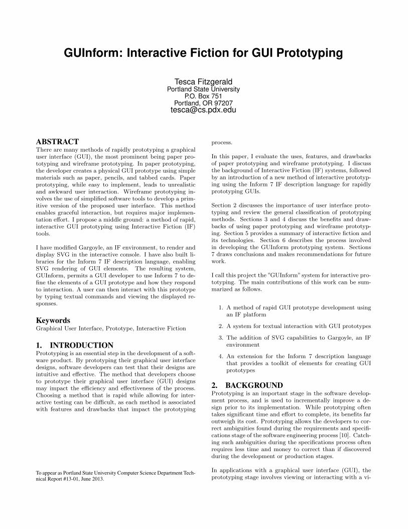
Figure 1: A Simple Paper Prototype [21]
the product. After the developer has given the test user atask to complete, such as ”Locate the product informationpage,” the test user interacts with the prototype to completethe task. By reviewing or recording the test user’s interac-tions with the prototype, the developer can learn whetherthe interface design is intuitive, e↵ective, and meets the in-terface design criteria. Changes may then be made to en-hance the prototype in response to this testing feedback.
3. PAPER PROTOTYPINGPaper prototyping is a common method of application pro-totyping for usability testing, and was first used in the early1990’s [23]. This method is a form of exploratory proto-typing, as it is an easily implemented method of exploringpotential user interface designs. The aim of this form ofprototyping is to create a presentation prototype that mayillustrate the proposed interface, but does not allow for easyusability or functionality testing. Creating a paper proto-typing consists of using pen, paper, and other common craftsupplies to create a prototype of the proposed user inter-face. Elements of the interface are drawn onto the paper.Figure 1 depicts an example of a paper prototype of a web-site’s shopping cart page.
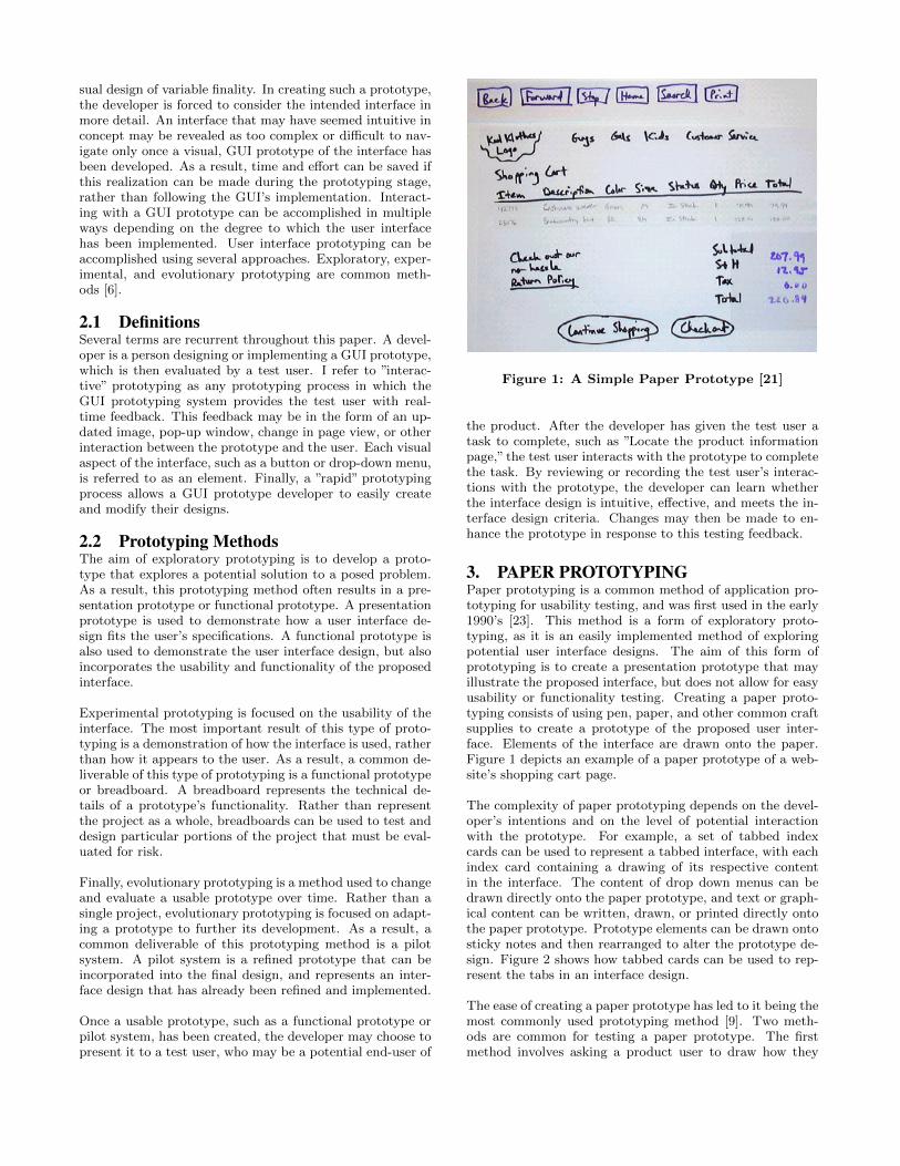
The complexity of paper prototyping depends on the devel-oper’s intentions and on the level of potential interactionwith the prototype. For example, a set of tabbed indexcards can be used to represent a tabbed interface, with eachindex card containing a drawing of its respective contentin the interface. The content of drop down menus can bedrawn directly onto the paper prototype, and text or graph-ical content can be written, drawn, or printed directly ontothe paper prototype. Prototype elements can be drawn ontosticky notes and then rearranged to alter the prototype de-sign. Figure 2 shows how tabbed cards can be used to rep-resent the tabs in an interface design.
The ease of creating a paper prototype has led to it being themost commonly used prototyping method [9]. Two meth-ods are common for testing a paper prototype. The firstmethod involves asking a product user to draw how they
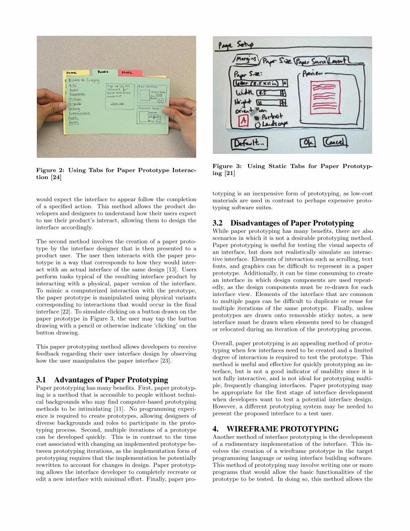
Figure 2: Using Tabs for Paper Prototype Interac-tion [24]
would expect the interface to appear follow the completionof a specified action. This method allows the product de-velopers and designers to understand how their users expectto use their product’s interact, allowing them to design theinterface accordingly.
The second method involves the creation of a paper proto-type by the interface designer that is then presented to aproduct user. The user then interacts with the paper pro-totype in a way that corresponds to how they would inter-act with an actual interface of the same design [13]. Usersperform tasks typical of the resulting interface product byinteracting with a physical, paper version of the interface.To mimic a computerized interaction with the prototype,the paper prototype is manipulated using physical variantscorresponding to interactions that would occur in the finalinterface [22]. To simulate clicking on a button drawn on thepaper prototype in Figure 3, the user may tap the buttondrawing with a pencil or otherwise indicate ’clicking’ on thebutton drawing.
This paper prototyping method allows developers to receivefeedback regarding their user interface design by observinghow the user manipulates the paper interface [23].
3.1 Advantages of Paper PrototypingPaper prototyping has many benefits. First, paper prototyp-ing is a method that is accessible to people without techni-cal backgrounds who may find computer-based prototypingmethods to be intimidating [11]. No programming experi-ence is required to create prototypes, allowing designers ofdiverse backgrounds and roles to participate in the proto-typing process. Second, multiple iterations of a prototypecan be developed quickly. This is in contrast to the timecost associated with changing an implemented prototype be-tween prototyping iterations, as the implementation form ofprototyping requires that the implementation be potentiallyrewritten to account for changes in design. Paper prototyp-ing allows the interface developer to completely recreate oredit a new interface with minimal e↵ort. Finally, paper pro-
Figure 3: Using Static Tabs for Paper Prototyp-ing [21]
totyping is an inexpensive form of prototyping, as low-costmaterials are used in contrast to perhaps expensive proto-typing software suites.
3.2 Disadvantages of Paper PrototypingWhile paper prototyping has many benefits, there are alsoscenarios in which it is not a desirable prototyping method.Paper prototyping is useful for testing the visual aspects ofan interface, but does not realistically simulate an interac-tive interface. Elements of interaction such as scrolling, textfonts, and graphics can be di�cult to represent in a paperprototype. Additionally, it can be time consuming to createan interface in which design components are used repeat-edly, as the design components must be re-drawn for eachinterface view. Elements of the interface that are commonto multiple pages can be di�cult to duplicate or reuse formultiple iterations of the same prototype. Finally, unlessprototypes are drawn onto removable sticky notes, a newinterface must be drawn when elements need to be changedor relocated during an iteration of the prototyping process.
Overall, paper prototyping is an appealing method of proto-typing when few interfaces need to be created and a limiteddegree of interaction is required to test the prototype. Thismethod is useful and e↵ective for quickly prototyping an in-terface, but is not a good indicator of usability since it isnot fully interactive, and is not ideal for prototyping multi-ple, frequently changing interfaces. Paper prototyping maybe appropriate for the first stage of interface developmentwhen developers want to test a potential interface design.However, a di↵erent prototyping system may be needed topresent the proposed interface to a test user.
4. WIREFRAME PROTOTYPINGAnother method of interface prototyping is the developmentof a rudimentary implementation of the interface. This in-volves the creation of a wireframe prototype in the targetprogramming language or using interface building software.This method of prototyping may involve writing one or moreprograms that would allow the basic functionalities of theprototype to be tested. In doing so, this method allows the
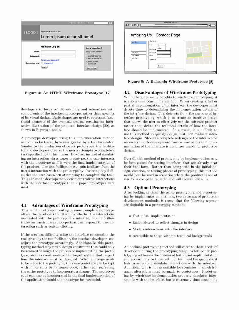
Figure 4: An HTML Wireframe Prototype [12]
developers to focus on the usability and interaction withcomponents of the interface prototype, rather than specificsof its visual design. Basic shapes are used to represent func-tional elements of the eventual design, creating an inter-active illustration of the proposed interface design [20], asshown in Figures 4 and 5.
A prototype developed using this implementation methodwould also be tested by a user guided by a test facilitator.Similar to the evaluation of paper prototypes, the facilita-tor and developers observe the user’s attempts to complete atask specified by the facilitator. However, instead of simulat-ing an interaction via a paper prototype, the user interactswith the prototype as if it were the final implementation ofthe product. The test facilitators can gain feedback from theuser’s interaction with the prototype by observing any di�-culties the user has when attempting to complete the task.This allows the developers to view more realistic interactionswith the interface prototype than if paper prototypes wereused.
4.1 Advantages of Wireframe PrototypingThis method of implementing a more complete prototypeallows the developers to determine whether the interactionsassociated with the prototype are intuitive. Figure 5 illus-trates an wireframe prototype that can respond to user in-teraction such as button clicking.
If the user has di�culty using the interface to complete thetask given by the test facilitator, the interface developers canadjust the prototype accordingly. Additionally, this proto-typing method may reveal design constraints that could onlybe realized through the process of implementing the proto-type, such as constraints of the target system that impacthow the interface must be designed. When a change needsto be made to the prototype, the same prototype can be keptwith minor edits to its source code, rather than recreatingthe entire prototype to incorporate a change. The prototypecode can also be incorporated in the final implementation ofthe application should the prototype be successful.
Figure 5: A Balsamiq Wireframe Prototype [8]
4.2 Disadvantages of Wireframe PrototypingWhile there are many benefits to wireframe prototyping, itis also a time consuming method. When creating a full orpartial implementation of an interface, the developer mustdevote time to determining the implementation details ofthe interface design. This detracts from the purpose of in-terface prototyping, which is to create an intuitive designthat allows the user to e↵ectively use the software productrather than define the technical details of how the inter-face should be implemented. As a result, it is di�cult touse this method to quickly design, test, and evaluate inter-face designs. Should a complete redesign of the interface benecessary, much development time is wasted, as the imple-mentation of the interface is no longer usable for prototypedesign.
Overall, this method of prototyping by implementation maybe best suited for testing interfaces that are already neartheir final form. Rather than being used in the initial de-sign, creation, or testing phases of prototyping, this methodwould best be used in scenarios where the product is not atrisk for a complete redesign and will require few edits.
4.3 Optimal PrototypingAfter looking at these the paper prototyping and prototyp-ing by implementation methods, two extremes of prototypedevelopment methods, it seems that the following aspectsare desirable in a prototyping method:
• Fast initial implementation
• Easily altered to reflect changes in design
• Models interactions with the interface
• Accessible to those without technical backgrounds
An optimal prototyping method will cater to these needs ofdevelopers during the prototyping stage. While paper pro-totyping addresses the criteria of fast initial implementationand accessibility to those without technical backgrounds, itfails to accurately simulate interactions with the interface.Additionally, it is not as suitable for scenarios in which fre-quent alterations must be made to prototypes. Prototyp-ing by wireframe implementation properly simulates inter-actions with the interface, but is extremely time consuming
to create initially and is not suitable for frequently changingdesigns. An optimal prototyping method will strike a bal-ance between the two extremes of the paper and wireframemethods.
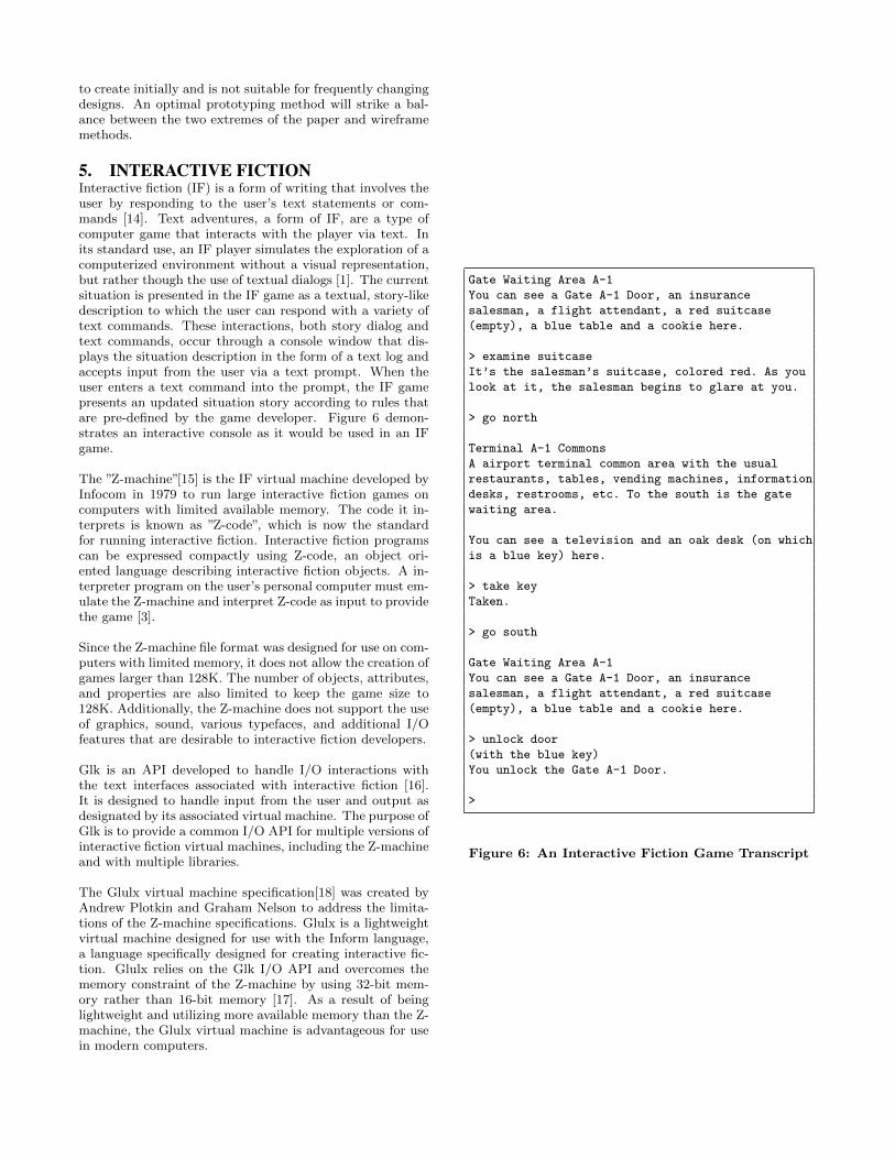
5. INTERACTIVE FICTIONInteractive fiction (IF) is a form of writing that involves theuser by responding to the user’s text statements or com-mands [14]. Text adventures, a form of IF, are a type ofcomputer game that interacts with the player via text. Inits standard use, an IF player simulates the exploration of acomputerized environment without a visual representation,but rather though the use of textual dialogs [1]. The currentsituation is presented in the IF game as a textual, story-likedescription to which the user can respond with a variety oftext commands. These interactions, both story dialog andtext commands, occur through a console window that dis-plays the situation description in the form of a text log andaccepts input from the user via a text prompt. When theuser enters a text command into the prompt, the IF gamepresents an updated situation story according to rules thatare pre-defined by the game developer. Figure 6 demon-strates an interactive console as it would be used in an IFgame.
The ”Z-machine”[15] is the IF virtual machine developed byInfocom in 1979 to run large interactive fiction games oncomputers with limited available memory. The code it in-terprets is known as ”Z-code”, which is now the standardfor running interactive fiction. Interactive fiction programscan be expressed compactly using Z-code, an object ori-ented language describing interactive fiction objects. A in-terpreter program on the user’s personal computer must em-ulate the Z-machine and interpret Z-code as input to providethe game [3].
Since the Z-machine file format was designed for use on com-puters with limited memory, it does not allow the creation ofgames larger than 128K. The number of objects, attributes,and properties are also limited to keep the game size to128K. Additionally, the Z-machine does not support the useof graphics, sound, various typefaces, and additional I/Ofeatures that are desirable to interactive fiction developers.
Glk is an API developed to handle I/O interactions withthe text interfaces associated with interactive fiction [16].It is designed to handle input from the user and output asdesignated by its associated virtual machine. The purpose ofGlk is to provide a common I/O API for multiple versions ofinteractive fiction virtual machines, including the Z-machineand with multiple libraries.
The Glulx virtual machine specification[18] was created byAndrew Plotkin and Graham Nelson to address the limita-tions of the Z-machine specifications. Glulx is a lightweightvirtual machine designed for use with the Inform language,a language specifically designed for creating interactive fic-tion. Glulx relies on the Glk I/O API and overcomes thememory constraint of the Z-machine by using 32-bit mem-ory rather than 16-bit memory [17]. As a result of beinglightweight and utilizing more available memory than the Z-machine, the Glulx virtual machine is advantageous for usein modern computers.
Gate Waiting Area A-1
You can see a Gate A-1 Door, an insurance
salesman, a flight attendant, a red suitcase
(empty), a blue table and a cookie here.
> examine suitcase
It’s the salesman’s suitcase, colored red. As you
look at it, the salesman begins to glare at you.
> go north
Terminal A-1 Commons
A airport terminal common area with the usual
restaurants, tables, vending machines, information
desks, restrooms, etc. To the south is the gate
waiting area.
You can see a television and an oak desk (on which
is a blue key) here.
> take key
Taken.
> go south
Gate Waiting Area A-1
You can see a Gate A-1 Door, an insurance
salesman, a flight attendant, a red suitcase
(empty), a blue table and a cookie here.
> unlock door
(with the blue key)
You unlock the Gate A-1 Door.
>
Figure 6: An Interactive Fiction Game Transcript
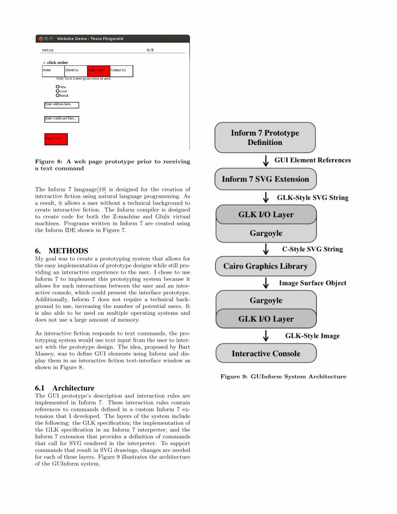
Figure 8: A web page prototype prior to receivinga text command
The Inform 7 language[19] is designed for the creation ofinteractive fiction using natural language programming. Asa result, it allows a user without a technical background tocreate interactive fiction. The Inform compiler is designedto create code for both the Z-machine and Glulx virtualmachines. Programs written in Inform 7 are created usingthe Inform IDE shown in Figure 7.
6. METHODSMy goal was to create a prototyping system that allows forthe easy implementation of prototype designs while still pro-viding an interactive experience to the user. I chose to useInform 7 to implement this prototyping system because itallows for such interactions between the user and an inter-active console, which could present the interface prototype.Additionally, Inform 7 does not require a technical back-ground to use, increasing the number of potential users. Itis also able to be used on multiple operating systems anddoes not use a large amount of memory.
As interactive fiction responds to text commands, the pro-totyping system would use text input from the user to inter-act with the prototype design. The idea, proposed by BartMassey, was to define GUI elements using Inform and dis-play them in an interactive fiction text-interface window asshown in Figure 8.
6.1 ArchitectureThe GUI prototype’s description and interaction rules areimplemented in Inform 7. These interaction rules containreferences to commands defined in a custom Inform 7 ex-tension that I developed. The layers of the system includethe following: the GLK specification; the implementation ofthe GLK specification in an Inform 7 interpreter; and theInform 7 extension that provides a definition of commandsthat call for SVG rendered in the interpreter. To supportcommands that result in SVG drawings, changes are neededfor each of these layers. Figure 9 illustrates the architectureof the GUInform system.
Figure 9: GUInform System Architecture
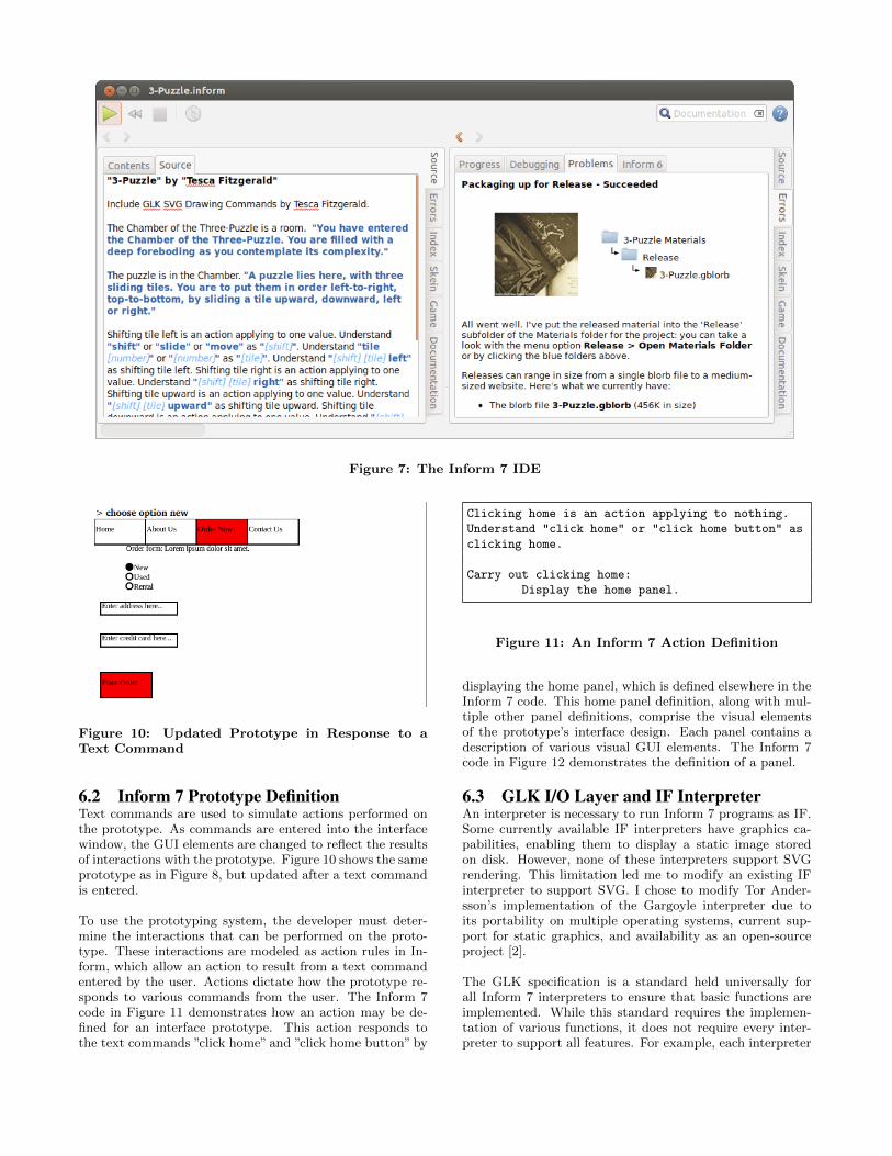
Figure 7: The Inform 7 IDE
Figure 10: Updated Prototype in Response to aText Command
6.2 Inform 7 Prototype DefinitionText commands are used to simulate actions performed onthe prototype. As commands are entered into the interfacewindow, the GUI elements are changed to reflect the resultsof interactions with the prototype. Figure 10 shows the sameprototype as in Figure 8, but updated after a text commandis entered.
To use the prototyping system, the developer must deter-mine the interactions that can be performed on the proto-type. These interactions are modeled as action rules in In-form, which allow an action to result from a text commandentered by the user. Actions dictate how the prototype re-sponds to various commands from the user. The Inform 7code in Figure 11 demonstrates how an action may be de-fined for an interface prototype. This action responds tothe text commands ”click home” and ”click home button” by
Clicking home is an action applying to nothing.
Understand "click home" or "click home button" as
clicking home.
Carry out clicking home:
Display the home panel.
Figure 11: An Inform 7 Action Definition
displaying the home panel, which is defined elsewhere in theInform 7 code. This home panel definition, along with mul-tiple other panel definitions, comprise the visual elementsof the prototype’s interface design. Each panel contains adescription of various visual GUI elements. The Inform 7code in Figure 12 demonstrates the definition of a panel.
6.3 GLK I/O Layer and IF InterpreterAn interpreter is necessary to run Inform 7 programs as IF.Some currently available IF interpreters have graphics ca-pabilities, enabling them to display a static image storedon disk. However, none of these interpreters support SVGrendering. This limitation led me to modify an existing IFinterpreter to support SVG. I chose to modify Tor Ander-sson’s implementation of the Gargoyle interpreter due toits portability on multiple operating systems, current sup-port for static graphics, and availability as an open-sourceproject [2].
The GLK specification is a standard held universally forall Inform 7 interpreters to ensure that basic functions areimplemented. While this standard requires the implemen-tation of various functions, it does not require every inter-preter to support all features. For example, each interpreter
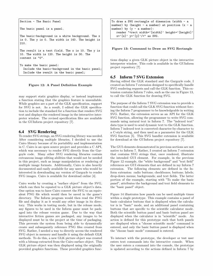
Section - The Basic Panel
The basic panel is a panel.
The basic-background is a white background. The x
is 0. The y is 0. The width is 140. The height is
210.
The result is a text field. The x is 10. The y is
10. The width is 120. The height is 30. The
content is "0".
To make the basic panel:
Include the basic-background in the basic panel;
Include the result in the basic panel;
Figure 12: A Panel Definition Example
may support static graphics display, or instead implementa function stating that the graphics feature is unavailable.While graphics are a part of the GLK specification, supportfor SVG is not. As a result, I edited the GLK specifica-tion to include the standard for a function that renders SVGtext and displays the rendered image in the interactive inter-preter window. The revised specification files are availablein the GUInform project repository [7].
6.4 SVG RenderingTo render SVG strings, an SVG rendering library was needed.After considering multiple libraries, I decided to use theCairo library because of its portability and implementationin C. Cairo is an open source project and provides a C API,which was necessary to render SVG directly from the Gar-goyle code. Many other SVG rendering libraries containextraneous image editing abilities that would not be neededin this project, such as image manipulation or rendering ofmultiple image formats. Additionally, Cairo is also heavilydocumented and easily available for any users who would beinterested in downloading my version of Gargoyle to renderSVG images. Cairo is available for download online [4].
Cairo works by creating a ”surface object” from the SVG,which can then be equated to a GLK picture object’s data.One option was to have Cairo convert the SVG to an equiv-alent PNG file which would then be saved in the game’sdirectory. The Inform program would then read the PNGfile and display it as it would any other image in its direc-tory. This works in testing mode, but in the release mode,any figures to be used in the Inform game must be pack-aged into the release version game. Due to the way thatinteractive fiction games are packaged, any images to bedisplayed must be in the project at the time of packaging.This prevents the system from being able to dynamicallycreate and subsequently reference PNG files created fromSVG. Rather, I needed a way to directly access the renderedSVG object in memory and handle it using the default GLKmethods. To do this, a new GLK picture object was createdwith a bitmap extracted from the Cairo surface object. ThisGLK picture object was then displayed using the originallyprovided graphics functions. These provided graphics func-
To draw a SVG rectangle of dimension (width - a
number) by (height - a number) at position (x - a
number) by (y - a number):
render "<rect width=’[width]’ height=’[height]’
x=’[x]’ y=’[y]’/>" as SVG.
Figure 13: Command to Draw an SVG Rectangle
tions display a given GLK picture object in the interactiveinterpreter window. This code is available in the GUInformproject repository [7].
6.5 Inform 7 SVG ExtensionHaving edited the GLK standard and the Gargoyle code, Icreated an Inform 7 extension designed to specifically handleSVG rendering requests and call the GLK function. This ex-tension contains Inform 7 rules, such as the one in Figure 13,to call the GLK function for drawing SVG.
The purpose of the Inform 7 SVG extension was to provide afunction that could call the GLK SVG function without forc-ing the Inform 7 programmer to be knowledgeable in writingSVG. Rather, the extension serves as an API for the GLKSVG function, allowing the programmer to write SVG com-mands using natural text in Inform 7. The ”indexed text”data type is used to send dynamic text to the GLK function.Inform 7 indexed text is converted character-by-character toa C-style string, and then used as a parameter for the GLKSVG function [5]. This SVG handler extension is availablefor download at the GUInform project repository [7].
The GUI elements demonstrated in previous sections are notnative to Inform 7. Rather, I created an Inform 7 extensionthat contains SVG strings that, once rendered, illustratethe intended GUI element. For example, in the previousFigure 12 example, the ”white background” and ”text field”references are GUI elements that are defined in my Inform 7extension. The following elements are defined in the In-form extension: radio buttons; checkboxes; buttons; labels;drop-down menus; backgrounds; and text fields. The latterportion of the example, starting with ”To make the basicpanel”, attributes the background and text field elements tothe ”basic panel” object.
Figure 14 illustrates how panels can be used multiple timeswithin a single prototype. This example contains a panel ofbasic calculator buttons that is displayed when the calcula-tor is in ”basic” mode, and an additional panel containingbuttons that are specific to the scientific calculator mode.Both the scientific button panel and basic button panel aredisplayed when the calculator is in ”scientific” mode. Anaction is defined for this prototype such that both panelsare displayed when a ”choose scientific mode” command isentered, and only the basic button panel is displayed whenthe ”choose basic mode” command is entered.
To interact with the prototype, the developer or test userenters text commands into the interactive console. Whenthe user enters a command into the console, the prototypeis updated according to the actions defined in Inform 7 by
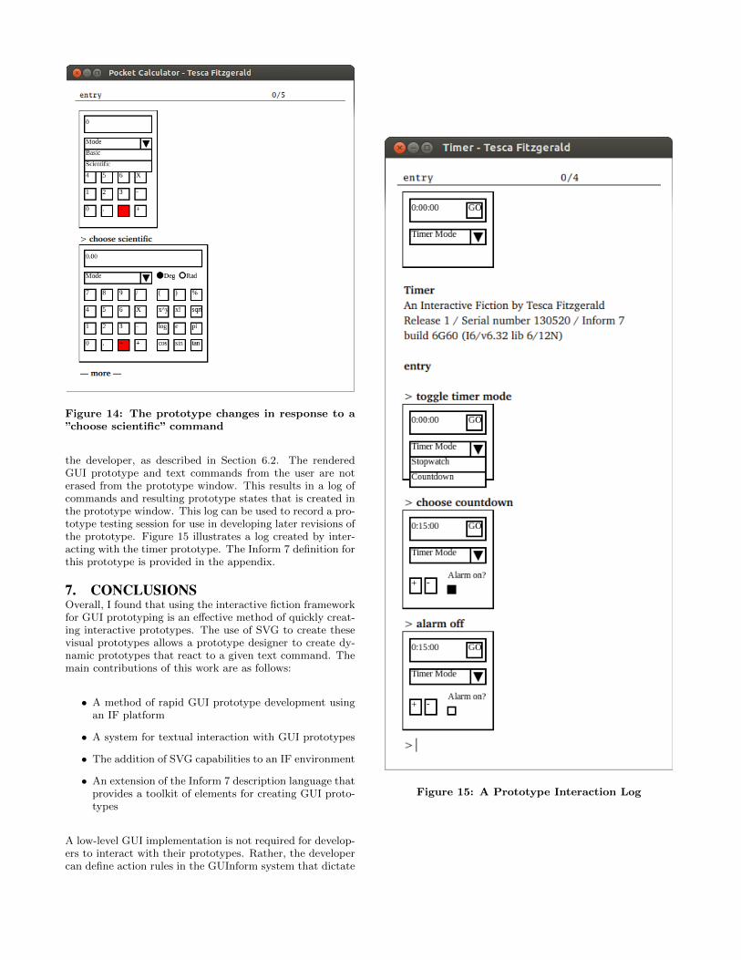
Figure 14: The prototype changes in response to a”choose scientific” command
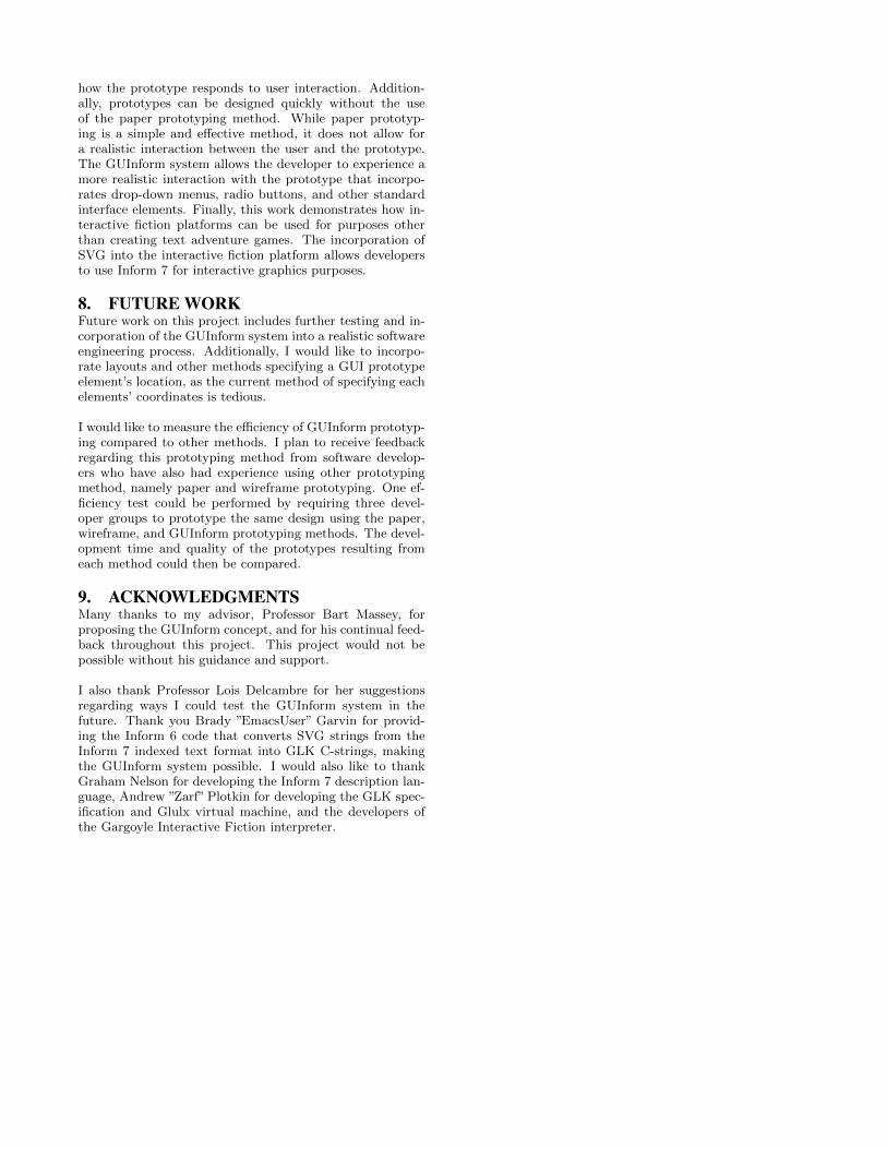
the developer, as described in Section 6.2. The renderedGUI prototype and text commands from the user are noterased from the prototype window. This results in a log ofcommands and resulting prototype states that is created inthe prototype window. This log can be used to record a pro-totype testing session for use in developing later revisions ofthe prototype. Figure 15 illustrates a log created by inter-acting with the timer prototype. The Inform 7 definition forthis prototype is provided in the appendix.
7. CONCLUSIONSOverall, I found that using the interactive fiction frameworkfor GUI prototyping is an e↵ective method of quickly creat-ing interactive prototypes. The use of SVG to create thesevisual prototypes allows a prototype designer to create dy-namic prototypes that react to a given text command. Themain contributions of this work are as follows:
• A method of rapid GUI prototype development usingan IF platform
• A system for textual interaction with GUI prototypes
• The addition of SVG capabilities to an IF environment
• An extension of the Inform 7 description language thatprovides a toolkit of elements for creating GUI proto-types
A low-level GUI implementation is not required for develop-ers to interact with their prototypes. Rather, the developercan define action rules in the GUInform system that dictate
Figure 15: A Prototype Interaction Log
how the prototype responds to user interaction. Addition-ally, prototypes can be designed quickly without the useof the paper prototyping method. While paper prototyp-ing is a simple and e↵ective method, it does not allow fora realistic interaction between the user and the prototype.The GUInform system allows the developer to experience amore realistic interaction with the prototype that incorpo-rates drop-down menus, radio buttons, and other standardinterface elements. Finally, this work demonstrates how in-teractive fiction platforms can be used for purposes otherthan creating text adventure games. The incorporation ofSVG into the interactive fiction platform allows developersto use Inform 7 for interactive graphics purposes.
8. FUTURE WORKFuture work on this project includes further testing and in-corporation of the GUInform system into a realistic softwareengineering process. Additionally, I would like to incorpo-rate layouts and other methods specifying a GUI prototypeelement’s location, as the current method of specifying eachelements’ coordinates is tedious.
I would like to measure the e�ciency of GUInform prototyp-ing compared to other methods. I plan to receive feedbackregarding this prototyping method from software develop-ers who have also had experience using other prototypingmethod, namely paper and wireframe prototyping. One ef-ficiency test could be performed by requiring three devel-oper groups to prototype the same design using the paper,wireframe, and GUInform prototyping methods. The devel-opment time and quality of the prototypes resulting fromeach method could then be compared.
9. ACKNOWLEDGMENTSMany thanks to my advisor, Professor Bart Massey, forproposing the GUInform concept, and for his continual feed-back throughout this project. This project would not bepossible without his guidance and support.
I also thank Professor Lois Delcambre for her suggestionsregarding ways I could test the GUInform system in thefuture. Thank you Brady ”EmacsUser” Garvin for provid-ing the Inform 6 code that converts SVG strings from theInform 7 indexed text format into GLK C-strings, makingthe GUInform system possible. I would also like to thankGraham Nelson for developing the Inform 7 description lan-guage, Andrew ”Zarf” Plotkin for developing the GLK spec-ification and Glulx virtual machine, and the developers ofthe Gargoyle Interactive Fiction interpreter.
10. REFERENCES[1] About interactive fiction.
http://www.inform7.com/if. Accessed 2013-05-25.[2] garglk - a cross-platform io layer for an interactive
fiction player. http://code.google.com/p/garglk/.Accessed 2013-05-27.
[3] How to fit a large program into a small machine. http://www.csd.uwo.ca/Infocom/Articles/small.html,Jul 1995. Accessed 2013-01-03.
[4] Cairo. http://www.cairographics.org, March 2012.Accessed 2013-05-28.
[5] Indexed text to glk function using if6.http://www.intfiction.org/forum/viewtopic.php?
t=5518&p=40129, August 2012. Accessed 2013-05-28.[6] Dirk Baumer, Walter R. Bischofberger, Horst Lichter,
and Heinz Zullighoven. User interfaceprototyping–concepts, tools, and experience. InProceedings of the 18th international conference on
Software engineering, ICSE ’96, pages 532–541,Washington, DC, USA, 1996. IEEE Computer Society.
[7] Tesca Fitzgerald.http://github.com/TescaF/GUInform. Accessed2013-05-28.
[8] Gus Fraser. Balsamiq vs powerpoint storyboardingwith vs 2012.http://techblurt.com/2012/09/13/balsamiq-vs-
powerpoint-storyboarding-with-vs-2012/,September 2012. Accessed 2013-05-19.
[9] Tracy Frayne. Tools of i.a. focus on prototyping.http://csusap.csu.edu.au/~tfrayn01/
paperprototyping.html, June 2010. Accessed2013-05-27.
[10] Hassan Gomaa and B.H. Scott Douglas. Prototypingas a tool in the specification of user requirements.IEEE, pages 333–342, 1981.
[11] J.A. Landay and B.A. Myers. Sketching interfaces:Toward more human interface design. IEEEComputer, 34, 2001.
[12] Patrick Lynch and Sarah Horton. The design process.http://webstyleguide.com/wsg3/10-forms-and-
applications/4-design-process.html. Accessed2013-05-28.
[13] Shawn Medero. Paper prototyping.http://alistapart.com/article/paperprototyping,January 2007. Accessed 2013-05-23.
[14] Stuart Moulthrop and Nancy Kaplan. Something toimagine: Literature, composition and interactivefiction. Computers and Composition, 9(1):7–23, Nov1991.
[15] Graham Nelson. The z-machine standards document.http://www.gnelson.demon.co.uk/zspec/, June1997. Accessed 2013-01-03.
[16] Andrew Plotkin. Glk api specification.http://eblong.com/zarf/glk/glk-spec-074.txt.Accessed 2013-01-03.
[17] Andrew Plotkin. Glulx: A 32-bit virtual machine forif. http://www.eblong.com/zarf/glulx/, October2012. Accessed 2013-01-03.
[18] Andrew Plotkin. Glulx specifications. http://www.eblong.com/zarf/glulx/glulx-spec_0.html,October 2012. Accessed 2013-01-03.
[19] Aaron Reed. Creating Interactive Fiction with Inform
7. Course Technology Press, Boston, MA, UnitedStates, 1st edition, 2010.
[20] Garr Reynolds. The importance of wireframes in webdesign and 9 tools to create wireframes.http://www.onextrapixel.com/2009/07/15/the-
importance-of-wireframes-in-web-design-and-9-
tools-to-create-wireframes/, July 2009. Accessed2013-05-27.
[21] Caroline Snyder. Paper prototyping.http://www.snyderconsulting.net/article_
paperprototyping.htm. Accessed 2013-05-28.[22] Caroline Snyder. Using paper prototypes to manage
risk.http://www.uie.com/articles/prototyping_risk/.Accessed 2013-01-02.
[23] Carolyn Snyder. Paper Prototyping: The Fast and
Easy Way to Design and Refine User Interface.Morgan Kaufmann, 1st edition, April 2003.
[24] Terry Winograd and Bill Verplank. Paper prototyping- climate control.http://hci.stanford.edu/courses/cs247/2009/
handouts/paper-2009-exercise.html, 2009.Accessed 2013-05-28.
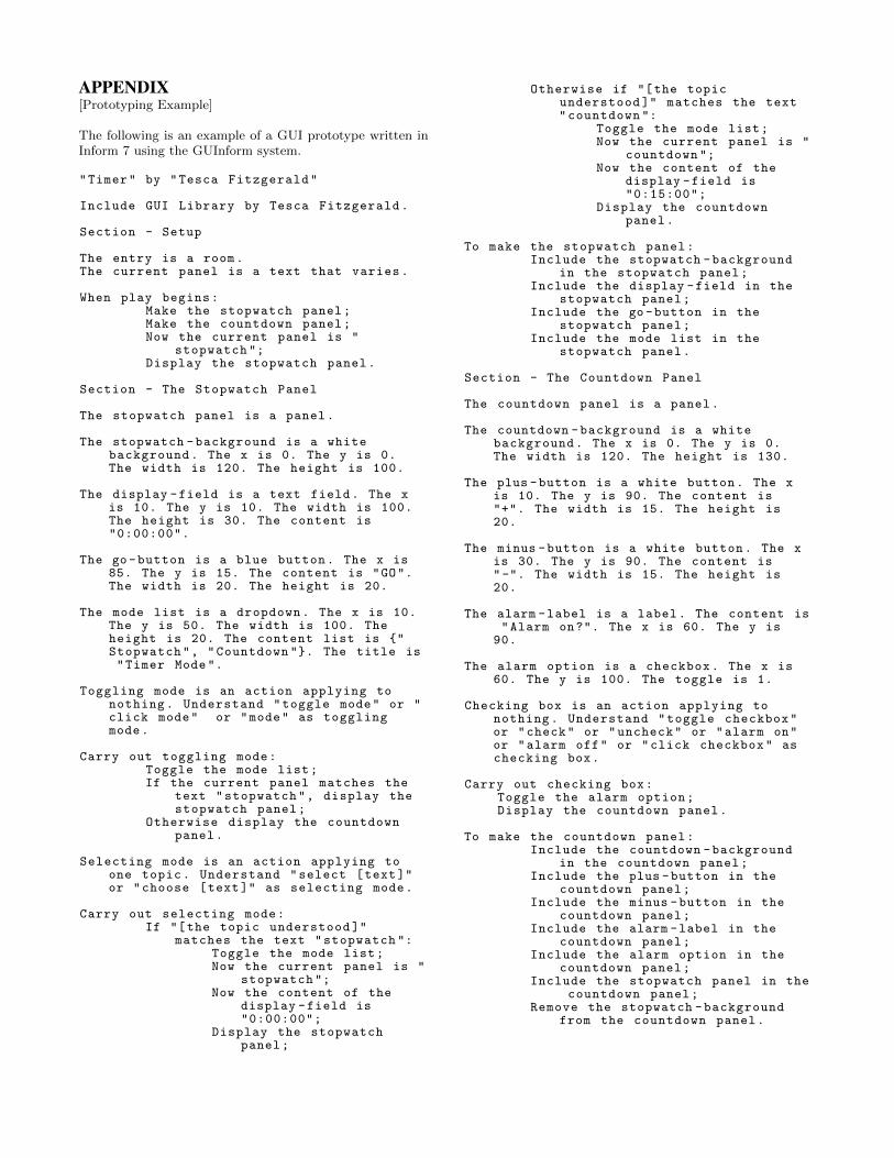
APPENDIX[Prototyping Example]
The following is an example of a GUI prototype written inInform 7 using the GUInform system.
"Timer" by "Tesca Fitzgerald"
Include GUI Library by Tesca Fitzgerald.
Section - Setup
The entry is a room.The current panel is a text that varies.
When play begins:Make the stopwatch panel;Make the countdown panel;Now the current panel is "
stopwatch ";Display the stopwatch panel.
Section - The Stopwatch Panel
The stopwatch panel is a panel.
The stopwatch -background is a whitebackground. The x is 0. The y is 0.The width is 120. The height is 100.
The display -field is a text field. The xis 10. The y is 10. The width is 100.The height is 30. The content is"0:00:00".
The go-button is a blue button. The x is85. The y is 15. The content is "GO".The width is 20. The height is 20.
The mode list is a dropdown. The x is 10.The y is 50. The width is 100. Theheight is 20. The content list is {"Stopwatch", "Countdown "}. The title is"Timer Mode".
Toggling mode is an action applying tonothing. Understand "toggle mode" or "click mode" or "mode" as togglingmode.
Carry out toggling mode:Toggle the mode list;If the current panel matches the
text "stopwatch", display thestopwatch panel;
Otherwise display the countdownpanel.
Selecting mode is an action applying toone topic. Understand "select [text]"or "choose [text]" as selecting mode.
Carry out selecting mode:If "[the topic understood ]"
matches the text "stopwatch ":Toggle the mode list;Now the current panel is "
stopwatch ";Now the content of the
display -field is"0:00:00";
Display the stopwatchpanel;
Otherwise if "[the topicunderstood ]" matches the text"countdown ":
Toggle the mode list;Now the current panel is "
countdown ";Now the content of the
display -field is"0:15:00";
Display the countdownpanel.
To make the stopwatch panel:Include the stopwatch -background
in the stopwatch panel;Include the display -field in the
stopwatch panel;Include the go-button in the
stopwatch panel;Include the mode list in the
stopwatch panel.
Section - The Countdown Panel
The countdown panel is a panel.
The countdown -background is a whitebackground. The x is 0. The y is 0.The width is 120. The height is 130.
The plus -button is a white button. The xis 10. The y is 90. The content is"+". The width is 15. The height is20.
The minus -button is a white button. The xis 30. The y is 90. The content is"-". The width is 15. The height is20.
The alarm -label is a label. The content is"Alarm on?". The x is 60. The y is
90.
The alarm option is a checkbox. The x is60. The y is 100. The toggle is 1.
Checking box is an action applying tonothing. Understand "toggle checkbox"or "check" or "uncheck" or "alarm on"or "alarm off" or "click checkbox" aschecking box.
Carry out checking box:Toggle the alarm option;Display the countdown panel.
To make the countdown panel:Include the countdown -background
in the countdown panel;Include the plus -button in the
countdown panel;Include the minus -button in the
countdown panel;Include the alarm -label in the
countdown panel;Include the alarm option in the
countdown panel;Include the stopwatch panel in the
countdown panel;Remove the stopwatch -background
from the countdown panel.