gujarat technological university€¦ · q.5 (a) give the advantages of bode plots. 04 (b) sketch...
TRANSCRIPT

1
Seat No.: _____________ Enrolment No._____________
GUJARAT TECHNOLOGICAL UNIVERSITY P.D.D.C. Sem- III Examination December 2010
Subject code: X30903
Subject Name: Control Theory
Date: 15 /12 /2010 Time: 10.30 am – 01.00 pm
Total Marks: 70
Instructions: 1. Attempt all questions.
2. Make suitable assumptions wherever necessary.
3. Figures to the right indicate full marks.
4. Use of Graph Paper / Semi-log Graph Paper is permissible.
Q.1 (a) What is control system? State types of control systems. Explain in brief open
loop and closed loop control system with suitable example. Also compare both
the systems.
07
(b) Using block diagram reduction technique find the closed loop transfer function
of the system whose block diagram is shown in Fig.1.
07
Q.2 (a) Define term signal flow graph and using Manson’s gain formula obtain overall
transfer function of signal flow graph shown in Fig.2.
07
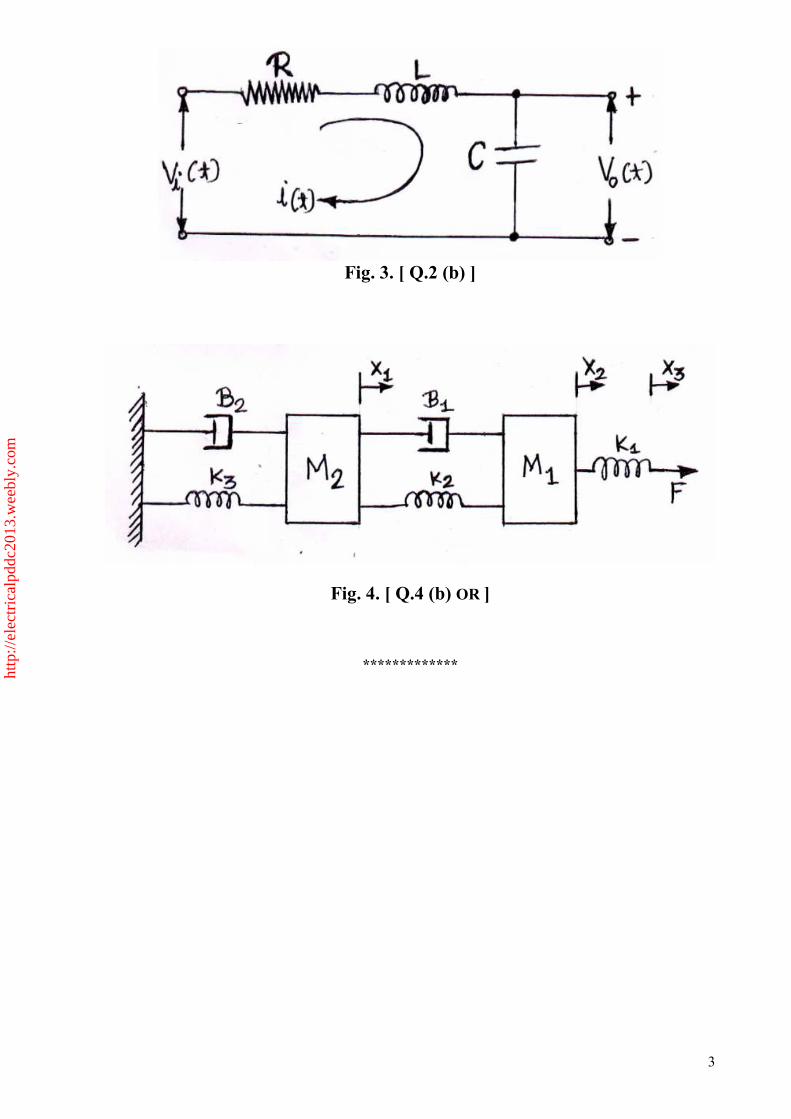
(b) Obtain the state space model of the electrical system shown in Fig.3. 07
OR
(b) (i) Determine the range of K for system to be stable. The characteristic
equation of the system is, 3 23 ( 2 ) 4 0S K S K S+ + + + =
(ii) Using Routh criterion, determine the stability of following system. If
system is unstable determine the number of roots in right half of the s-
plane. 4 3 22 4 2 0S S S S+ + + + =
04
03
Q.3 (a) What is root-locus? State and define types of root- locus. 04
(b) A unity feedback control system has an open-loop transfer function
2( )
( 4 1 3)
KG s
s s s=
+ +
Sketch the root-locus plot of the system by determining the following.
(i) Number and angle of Asymptotes.
(ii) Centroid.
(iii) Break away points if any.
(iv) Angle of departure of root loci from the imaginary poles.
(v) The value of K and the frequency at which the root loci cross the
imaginary axis.
10
OR
Q.3 (a) Sketch the polar plot of the following transfer function. Determine whether the
plot crosses the real axis and imaginary axis. If so, determine the frequency at
which these axes are crossed and corresponding magnitudes.
1( )
(1 )(1 2 )G s
s s=
+ +
07
(b) Compare Block diagram and Signal flow graph method. 07
http
://el
ectr
ical
pddc
2013
.wee
bly.
com
2
Q.4 (a) Define steady state error. Derive equation for steady state error (ess). 07
(b) Define thermal resistance and thermal capacitance. Explain thermal systems. 07
OR
Q.4 (a) Define Following term:
(i) State.
(ii) State Variables.
(iii) State Vector.
(iv) State Space.
04
(b) Obtain differential equations describing the mechanical system shown in Fig.4
and Draw the electric network using force- voltage analogy.
10
Q.5 (a) Give the advantages of bode plots. 04
(b) Sketch Bode plots of a control system having transfer function as given below.
Determine gain margin and phase margin.
10( ) ( )
( 1)( 10)G s H s
s s s=
+ +
10
OR
Q.5 (a) Explain constant-M circles and constant-N circles by deriving related
expressions.
06
(b) Draw Nyquist plot for system having transfer function
1 2
1( )
( )( )GH s
s p s p=
+ +
Where 1 2, 0p p >
08
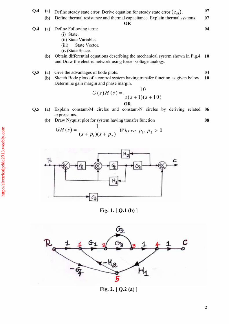
Fig. 1. [ Q.1 (b) ]
Fig. 2. [ Q.2 (a) ]
http
://el
ectr
ical
pddc
2013
.wee
bly.
com
3
Fig. 3. [ Q.2 (b) ]
Fig. 4. [ Q.4 (b) OR ]
*************
http
://el
ectr
ical
pddc
2013
.wee
bly.
com

1
Seat No.: _____________ Enrolment No._______________
GUJARAT TECHNOLOGICAL UNIVERSITY P.D.D.C Sem-III Examination May 2011
Subject code: X30903 Subject Name: Control Theory Date:25/05/2011 Time: 10.30 am – 01.00 pm
Total Marks: 70
Instructions: 1. Attempt all questions. 2. Make suitable assumptions wherever necessary. 3. Figures to the right indicate full marks.
4. Use of Graph Paper / Semi-log Graph Paper is permissible.
Q.1 (a) State and explain the necessary and sufficient conditions as applied to
Routh hurwittz criterion, so that all the roots of the characteristic equation
F(S) lie in the left half of the s Space.
07
(b) State and explain the principle of arguments. How it is applied in the
Nyquist stability criterion to determine system stability 07
Q.2 (a) Define term signal flow graph and using Manson’s gain formula. 04
(b) The characteristics equation of a system in differential equation form is
- (K+2) + 92K+5) x = 0 find the values of K for which the system is
(i) stable (ii) limitedly stable (iii)Unstable
10
OR
(b) Explain the time domain specification for transient response of second
order system with the unit step input with diagram 10
Q.3 (a) What is root-locus? State and define types of root- locus. 04
(b) A unity feedback control system has an open-loop transfer function
Sketch the root-locus plot. Determine the value of K for which all the roots
are equal. What is the value of these roots?
10
OR
Q.3 (a) Define Following term:
(i) State.
(ii) State Variables.
(iii)State Vector.
(iv) State Space.
07
(b) Compare Block diagram and Signal flow graph method. 07
Q.4 (a) Define steady state error. Derive equation for steady state error (ess). 07
(b) Explain in brief the frequency response specifications and time response
specifications 07
http
://el
ectr
ical
pddc
2013
.wee
bly.
com

2
OR
Q.4 (a) Mention the types of rules used for the block diagram reduction technique. 07
(b) State and explain necessary sufficient condition as applied to R-H Criterion
so that all the roots of the characteristic equation F(s) lie in the left half of
the S plane.
07
Q.5 (a) Give the advantages of bode plots. 04
(b) Sketch the Nyquist plot of the open loop transfer function of unity feedback
control systems
10
OR
Q.5 (a) Explain the general procedure for constructing the Bode Plot 07
(b) What is analogues system, explain the force voltage and force current
analogy with suitable example. 07
*************
http
://el
ectr
ical
pddc
2013
.wee
bly.
com
Page 1 of 3
Seat No.: _________ Enrolment No._______________
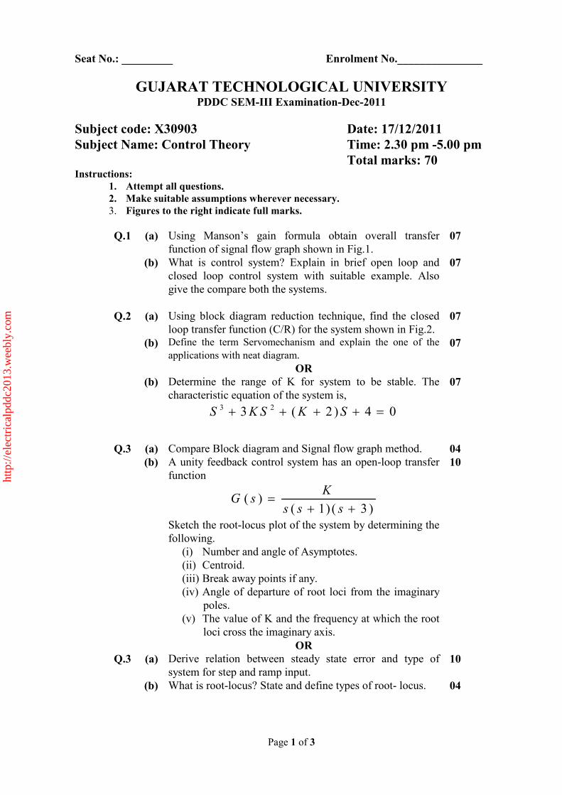
GUJARAT TECHNOLOGICAL UNIVERSITY PDDC SEM-III Examination-Dec-2011
Subject code: X30903 Date: 17/12/2011
Subject Name: Control Theory Time: 2.30 pm -5.00 pm
Total marks: 70 Instructions:
1. Attempt all questions.
2. Make suitable assumptions wherever necessary.
3. Figures to the right indicate full marks.
Q.1 (a) Using Manson’s gain formula obtain overall transfer
function of signal flow graph shown in Fig.1.
07
(b) What is control system? Explain in brief open loop and
closed loop control system with suitable example. Also
give the compare both the systems.
07
Q.2 (a) Using block diagram reduction technique, find the closed
loop transfer function (C/R) for the system shown in Fig.2.
07
(b) Define the term Servomechanism and explain the one of the
applications with neat diagram. 07
OR
(b) Determine the range of K for system to be stable. The
characteristic equation of the system is, 3 23 ( 2 ) 4 0S K S K S+ + + + =
07
Q.3 (a) Compare Block diagram and Signal flow graph method. 04
(b) A unity feedback control system has an open-loop transfer
function
( )( 1) ( 3 )
KG s
s s s=
+ +
Sketch the root-locus plot of the system by determining the
following.
(i) Number and angle of Asymptotes.
(ii) Centroid.
(iii) Break away points if any.
(iv) Angle of departure of root loci from the imaginary
poles.
(v) The value of K and the frequency at which the root
loci cross the imaginary axis.
10
OR
Q.3 (a) Derive relation between steady state error and type of
system for step and ramp input.
10
(b) What is root-locus? State and define types of root- locus.
04
http
://el
ectr
ical
pddc
2013
.wee
bly.
com

Page 2 of 3
Q.4 (a) Sketch the polar plot of the following transfer function.
1 2
1( )
(1 )(1 )G s
P s P s=
+ +
10
(b) Give the advantages of bode plots. 04
OR
Q.4 (a) Derive equation for steady state error (ess). 04
Q.4 (b) Draw Nyquist plot for system having transfer function
1( )
( 1)GH s
s=
+
10
Q.5 (a) Explain thermal system. 04
(b) Sketch Bode plots of a control system having transfer
function as given below. Determine gain margin and phase
margin.
10( ) ( )
( 1)( 10)G s H s
s s s=
+ +
10
OR
Q.5 (a) Explain constant-M circles by deriving related expressions. 06
(b) Obtain differential equations describing the mechanical
system shown in Fig.3 and Draw the electric network using
force- voltage analogy.
08
Fig. 1. [Q. 1 (a)]
Fig. 2. [Q.2 (a)]
http
://el
ectr
ical
pddc
2013
.wee
bly.
com

Page 3 of 3
Fig. 3. [Q.5 (b), OR]
*************
http
://el
ectr
ical
pddc
2013
.wee
bly.
com

1
Seat No.: _____ Enrolment No.______
GUJARAT TECHNOLOGICAL UNIVERSITY
PDDC-Semester –III (May-2012) Examination
Subject code: X30903
Subject Name: CONTROL THEORY
Date: 16/05/2012
Time: 02.30 pm – 05.00 pm Total Marks: 70
Instructions: 1. Attempt all questions.
2. Make suitable assumptions wherever necessary.
3. Figures to the right indicate full marks.
Q.1 (a) Establish correlation between transfer function and state space equation. 07
(b) Discuss basic principle for obtaining derivative control action. Explain effect of
P and PD controller with suitable example. 07
Q.2 (a) Discuss major advantages and disadvantages of open loop control system.
Compare it with closed loop control systems. 07
(b) For the system shown in Figure-1, obtain the closed loop transfer function
Y(s)/X(s) by use of Mason’s fain formula. 07
OR
(b) For the system shown in Figure-2, obtain the closed loop transfer function
Y(s)/U(s) by use of block diagram reduction technique. 07
Q.3 (a) Discuss unit step response curve showing transient response specifications:
delay time (td), rise time (tr), peak time (tp), maximum overshoot (Mp) and
settling time (ts). Discuss these specifications for the second order system.
07
(b) Discuss steady state error in unity feedback control system. Explain static
position, velocity and acceleration error constants. 07
OR
Q.3 (a) Explain procedure to check system stability using Routh’s stability criterion.
Discuss special cases. 07
(b) With appropriate example discuss effect of integral and derivative control
actions on system performance. 07
Q.4 (a) What is root locus? Discuss angle and magnitude conditions. For the feedback
system with , ; find angle and magnitude conditions.
07
(b) What is transportation lag? Obtain magnitude and angle conditions for the
system with , .
07
OR
Q.4 (a) Discuss in brief, general rules for construction of root loci. 07
(b) Explain conditionally stable systems with appropriate example. 07
Q.5 (a) Draw Bode magnitude and phase diagram for;
• Gain (K)
• Derivative and Integral factors
• First order factors
07
(b) Discuss phase margin and gain margin of stable and unstable system with the
help of (a) Bode diagrams and (b) Polar plots. 07
OR
http
://el
ectr
ical
pddc
2013
.wee
bly.
com

2
Q.5 (a) Discuss minimum phase and non minimum phase systems. Draw pole zero
configuration and discuss phase angle characteristics of minimum phase and
non minimum phase systems.
07
(b) Sketch the polar plot for the transfer function . 07
Figure-1 Block diagram representation for Q. 2(b)
Figure-2 Block diagram representation for Q. 2(b) OR
*************
http
://el
ectr
ical
pddc
2013
.wee
bly.
com

Seat No.: ________ Enrolment No.______________
GUJARAT TECHNOLOGICAL UNIVERSITY PDDC - SEMESTER – III • EXAMINATION – WINTER 2012
Subject code: X 30903 Date: 31/12/2012 Subject Name: Control Theory Time: 10.30 am - 01.00 pm Total Marks: 70 Instructions:
1. Attempt all questions. 2. Make suitable assumptions wherever necessary. 3. Figures to the right indicate full marks.
Q.1 (a) Compare closed loop versus open loop control system. 07
(b) Establish relationship between transfer function and state space equation.
07
Q.2 (a) Simplify the block diagram shown in figure-1. 07
(b) For the mechanical system shown in figure-2, write state space equations.
07
OR (b) For the electrical system shown in figure-3, write state space
equations. 07
Q.3 (a) Find transfer function using Mason’s gain formula for the system
shown in figure-1. 07
(b) Explain thermal systems in brief. Also define thermal resistance and thermal capacitance.
07
OR Q.3 (a) Explain liquid systems in brief. Also define resistance and
capacitance of liquid level system. 07
(b) Discuss step response of second order system for underdamped, critically damped and overdamped cases.
07
Q.4 (a) Discuss various transient response specifications. 07
(b) For the system shown in figure-4, =0.6, =5 rad/sec. Find rise time , peak time , Maximum overshoot and settling time when the unit step input is applied to the system.
07
OR Q.4 (a) Mention procedure of Routh’s stability criterion. Discuss special
cases with suitable example. 07
Q.4 (b) Consider the closed loop system shown in figure-5. Determine the range of K for stability. Assume K>0.
07
Q.5 (a) Draw the root locus for the system shown in figure-6. 07
(b) Discuss Nyquist stability criterion. Comment on stability analysis. 07 OR
Q.5 (a) Find gain and phase margin for the system shown in figure-7 using bode plot technique. Here K=10.
07
(b) Explain root loci for system with transport lag. 07
P.T.O. *************
1
http
://el
ectr
ical
pddc
2013
.wee
bly.
com

Subject code: X30903 Subject Name: CONTROL THEORY
FIGURES
Fig. 1
Fig. 2
Fig. 3
Fig. 4 Fig. 5
Fig. 6 Fig. 7 2
http
://el
ectr
ical
pddc
2013
.wee
bly.
com

1
Seat No.: ________ Enrolment No.___________
GUJARAT TECHNOLOGICAL UNIVERSITY PDDC - SEMESTER–III • EXAMINATION – SUMMER 2013
Subject Code: X 30903 Date: 15-05-2013 Subject Name: Control Theory Time: 02.30 pm - 05.00 pm Total Marks: 70 Instructions:
1. Attempt all questions. 2. Make suitable assumptions wherever necessary. 3. Figures to the right indicate full marks.
Q.1 (a) Discuss translational-rotational elements. 07
(b) Find out the transfer function using Mason’s Gain Formula for the block diagram: (fig. 1).
Fig. 1
07
Q.2 (a) Compare the Closed Loop System and Open Loop System. Draw the block diagram for an automatic temperature controlled a class room of your college.
07
(b) Draw the block diagram for the following Mechanical Systems and derive the transfer function: (fig.2)
Fig. 2
07
OR (b) Draw the block diagram for the following Mechanical Systems and derive the
transfer function: (fig.3) 07
http
://el
ectr
ical
pddc
2013
.wee
bly.
com

2
Fig. 3
Q.3 (a) Explain force-voltage analogy with suitable example. 07 (b) Define the following terms:
a) Phase Margin b) Gain Margin
c) Non touching Loop d) Loop Gain
e) Closed Loop System f) Feedback g) Overshoot
07
OR Q.3 (a) Explain force-current analogy with suitable example. 07
(b) Define the following terms:
a) Delay Time b) Rise Time
c) Settling Time d) Peak Time
e) Steady State Error f) Mason’s Gain Formula
g) Maximum Overshoot
07
Q.4 (a) Draw the Bode Plot for the following Transfer Function:
10/(1+s)(4+s)
07
(b) Second order control system is depicted by:
.
A unit step is applied. Find the time response c(t) if (i) δ=1 and (ii) 0 < δ <1.
07
OR Q.4 (a) Draw the Bode Plot for the following Transfer Function:
1/s(1+s)2
07
Q.4 (b) Derive an expression for peak time tp, rise time tr and maximum overshoot in terms of natural frequency ωn and damping ratio ξ for a second order control system.
07
http
://el
ectr
ical
pddc
2013
.wee
bly.
com

3
Q.5 (a) Draw the Nyquist Plot for the following Transfer Function:
10/s2 (1+s)(1+2s)
07
(b) Consider a system with characteristic equation given below. Using R-H
criterion comments on its stability and find the number of roots in the right-half
of the s-plane if any.
07
OR Q.5 (a) Draw the Nyquist Plot for the following Transfer Function:
(1+0.2s)(1+0.025s)/s3(1+0.005s)(1+0.001s)
07
(b) For a unity feedback system having an open-loop transfer function:
Determine (a) type of system, (b) error constants Kp, Kv and Ka and
(c) steady-state error for unit step, unit ramp and unit parabolic inputs.
07
*************
http
://el
ectr
ical
pddc
2013
.wee
bly.
com

1
Seat No.: ________ Enrolment No.___________
GUJARAT TECHNOLOGICAL UNIVERSITY PDDC – SEMESTER – III • EXAMINATION – SUMMER 2014
Subject Code: X30903 Date: 24-06-2014
Subject Name: CONTROL THEORY
Time: 02:30 pm to 05:00 pm Total Marks: 70 Instructions:
1. Attempt all questions.
2. Make suitable assumptions wherever necessary.
3. Figures to the right indicate full marks.
Q.1 (a) Define STATE of control system & Derive the equation also explain the name
& size of each matrix
07
(b) Explain Force-Voltage & Force –current analogy 07
Q.2 (a) Compare Open loop & close loop System & Derive the equation for transfer
function for close loop system
07
(b) Derive STATSPACE model for RLC series circuit supplied by input voltage
source [ei]=Vm sin(wt) & eo=output use Fig-B
07
OR
(b) Explain Mason’s gain formula for signal flow with an example 07
Q.3 (a) Derive the electrical Equivalent model from Mechanical model of Fig-A, apply
Force current analogy
07
(b) Apply Block Reduction technique & derive transfer function of Fig-C 07
OR
Q.3 (a) Draw a nyquist plot for transfer function
07
(b) Define steady state error & derive the equation for steady state error 07
Q.4 (a) For given transfer function find the Value of damping ratio, natural frequency
;over shoot & Peak time
07
(b) Derive the relationship between steady state error & order of system, when
applied step input 07
OR
Q.4 (a) Explain the steps to draw root locus 07
(b) Check the system stability using Routh’s stability criteria for system having
characteristic equation;
S6+2S
5+8S
4+12S
3+16S+16=0
07
Q.5 (a) Sketch a polar plot for following transfer function
07
(b) Explain the advantages of state space over classical approaches & also define
State variable, State-space & state-vector
07
OR
http
://el
ectr
ical
pddc
2013
.wee
bly.
com

2
Q.5 (a) Draw a bode plot for below given transfer function & derive value for gain
margin & phase margin
10
(b) Explain various types of standard inputs used in control system 04
Fig-A
Fig-A
Fig-B
Fig-C
*************
http
://el
ectr
ical
pddc
2013
.wee
bly.
com

3
http
://el
ectr
ical
pddc
2013
.wee
bly.
com