gunawan wibisono dept electrical engineering university of indonesia
TRANSCRIPT

Gunawan WibisonoGunawan Wibisono
Dept electrical engineeringDept electrical engineeringuniversity of indonesiauniversity of indonesia

Agenda
Cable Modem DSL

Broadband Network

9.4
CABLE TV FOR DATA TRANSFERCABLE TV FOR DATA TRANSFER
Cable companies are now competing with telephone Cable companies are now competing with telephone companies for the residential customer who wants companies for the residential customer who wants high-speed data transfer. In this section, we briefly high-speed data transfer. In this section, we briefly discuss this technology.discuss this technology.
BandwidthSharingCM and CMTSData Transmission Schemes: DOCSIS
Topics discussed in this section:Topics discussed in this section:

9.5
Division of coaxial cable band by CATV

9.6
Downstream data are modulated using the 64-QAM modulation technique.
The theoretical downstream data rateis 30 Mbps.
Upstream data are modulated using the QPSK modulation technique.
The theoretical upstream data rate is 12 Mbps.

CEENET #8 8.2002 7
Changes in the Cable Network Changes in the Cable Network
• The cable network was designed to deliver TV signals in one direction from the Head-End to the subscribers homes
• To provide TV services Cable Operators had to recreate a portion of the over-the-air radio frequency (RF) spectrum within a sealed coaxial cable line
• Operators had to upgrade the cable network so that signals could flow in both directions

CEENET #8 8.2002 8
Changes in the Cable Network Changes in the Cable Network
• Cable Operators assign a spectrum of signal frequencies to the cable network
• One spectrum is used for the signals that move from the Head-End towards the cable subscriber
• Another spectrum of signal frequencies are used for the signals that move from the cable subscriber towards the Head-End

CEENET #8 8.2002 9
Changes in the Cable Network Changes in the Cable Network
• By replacing existing one way amplifiers with two way amplifiers Cable Operators are able to separate the upstream and downstream signals and amplify each direction separately in the right frequency range

CEENET #8 8.2002 10
Changes in the Cable Network Changes in the Cable Network
A Traditional Cable network

CEENET #8 8.2002 11
Changes in the Cable Network Changes in the Cable Network
A Modern Cable network

CEENET #8 8.2002 12
What is a Cable Modem? What is a Cable Modem?

9.13
Figure 9.17 Cable modem (CM)

9.14
Figure 9.18 Cable modem transmission system (CMTS)

CEENET #8 8.2002 15
How Fast is a Cable Modem? How Fast is a Cable Modem?
• Cable modem speeds vary widely – Depends on the cable modem system
– Cable network architecture
– Traffic load.
• In the downstream direction (from the network to the computer), network speeds can be up to 27 Mbps– BUT, this is an aggregate amount of bandwidth that is
shared by users.

CEENET #8 8.2002 16
How Fast is a Cable Modem? How Fast is a Cable Modem?
• Few computers will be capable of connecting at such high speeds or have exclusive access to the network– A more realistic number is 1 to 3 Mbps.
• In the upstream direction (from computer to network), speeds can be up to 10 Mbps. – However, most modem producers have selected a more
optimum speed between 500 Kbps and 2.5 Mbps
– AND, many cable operators limit the upstream bandwidth to 128 or 384kbs

CEENET #8 8.2002 17
How Fast is a Cable Modem? How Fast is a Cable Modem?
• An asymmetric cable modem scheme is most common. The downstream channel has a much higher bandwidth allocation (faster data rate) than the upstream,
• primarily because Internet applications tend to be asymmetric in nature.
• Activities such as World Wide Web (http) navigating and newsgroups reading (nntp) send much more data down to the computer than to the network.

CEENET #8 8.2002 18
How Fast is a Cable Modem? How Fast is a Cable Modem?
• Mouse clicks (URL requests) and e-mail messages are not bandwidth intensive in the upstream direction.
• Image files and streaming media (audio and video) are very bandwidth intensive in the downstream direction.

What is a Cable Modem &What is a Cable Modem & how does it work? how does it work?
A Cable Modem is a digital modem that uses a coaxial cable connection for the data transmission.
This data connection is received by a cable modem that decodes the signal into your PC.
http://www.cable-modems.org/tutorial/01.htm
http://www.cable-modems.org/tutorial/02.htm
MORE INFO...

How fast is a Cable Modem?How fast is a Cable Modem?
Cable modems are up to 10-20Mbps downloads. Typical downloads are over 300Kbps, or close to 600Kbps, but the speed of the cable modem depends on a few things.
First it depends on how many users are on the system since the cable technology is a "shared" bandwidth. Too many users using too much throughput can drain this “shared” technology.
The second factor to cable modem speed is a limit on the cable modem itself. Some cable providers will limit the upload or download speed on the cable modem, and this could affect your connection speed.
How secure is a Cable Modem?How secure is a Cable Modem?
Cable connections are not 100% secure in any instance like many other connections on the Internet. Even though most cable providers block ports 137-139, cable modems are likely to be generated in any case where a user has file and print sharing turned on, or possibly other services like SMTP (Simple mail transfer protocol), Web Servers and Telnet services. A general rule is to keep passwords long and turn off any service that you don't absolutely need running. A firewall type application should be used to keep a network as secure as possible.
CEENET #8 8.2002 22
Real-world performanceReal-world performance
• The theoretical performance of a Cable Modem is based upon all other devices being able to work at the same speed and performance as the Cable Modem
• However, in a similar way that the actual usable bandwidth on a 10Mbps Ethernet connection reduces to a 4Mbps, so too will the performance of a Cable Modem connection be reduced

CEENET #8 8.2002 23
Real-world performanceReal-world performance
• The Cable network itself will suffer the same problems of Internet performance as any other Internet Service Provider (ISP)
• Although performance to services on the cable network itself can be amazingly fast, access to 'the outside world' will be slowed down by the performance of other connections on the way.
CEENET #8 8.2002 24
Real-world performanceReal-world performance
• As usage on your segment grows (as more customers are added) the bandwidth must be shared by more people– Adding more cable network segments is very expensive
for the cable operator
• If you connect to a remote Internet site that itself has a connection speed equivalent to a T1 connection (1.5Mbps), then that is as fast as the data can be served to you, no matter how fast your receiving equipment is

CEENET #8 8.2002 25
Who Makes Cable Modems? Who Makes Cable Modems?
• 3Com, Cisco Systems, Com21, General Instrument, Motorola, Nortel Networks, Phasecom, Samsung, Terayon, Toshiba, Zenith
• And many others
CEENET #8 8.2002 26
• It MOdulates and DEModulates signals• Much more complicated than their telephone
counterparts• Cable modems can be part modem, part tuner, part
encryption/decryption device, part bridge, part router, part network interface card, part SNMP agent, and part Ethernet hub
Cable Modem Technology Cable Modem Technology

CEENET #8 8.2002 27
• Typically, a cable modem sends and receives data in two slightly different fashions– In the downstream direction
• he digital data is modulated and then placed on a typical 6 MHz television channel, somewhere between 50 MHz and 750 MHz
• 64 QAM is the preferred downstream modulation technique, offering up to 27 Mbps per 6 MHz channel
• This signal can be placed in a 6 MHz channel adjacent to TV signals on either side without disturbing the cable television video signals.
Cable Modem Technology Cable Modem Technology
CEENET #8 8.2002 28
Cable Modem Technology Cable Modem Technology
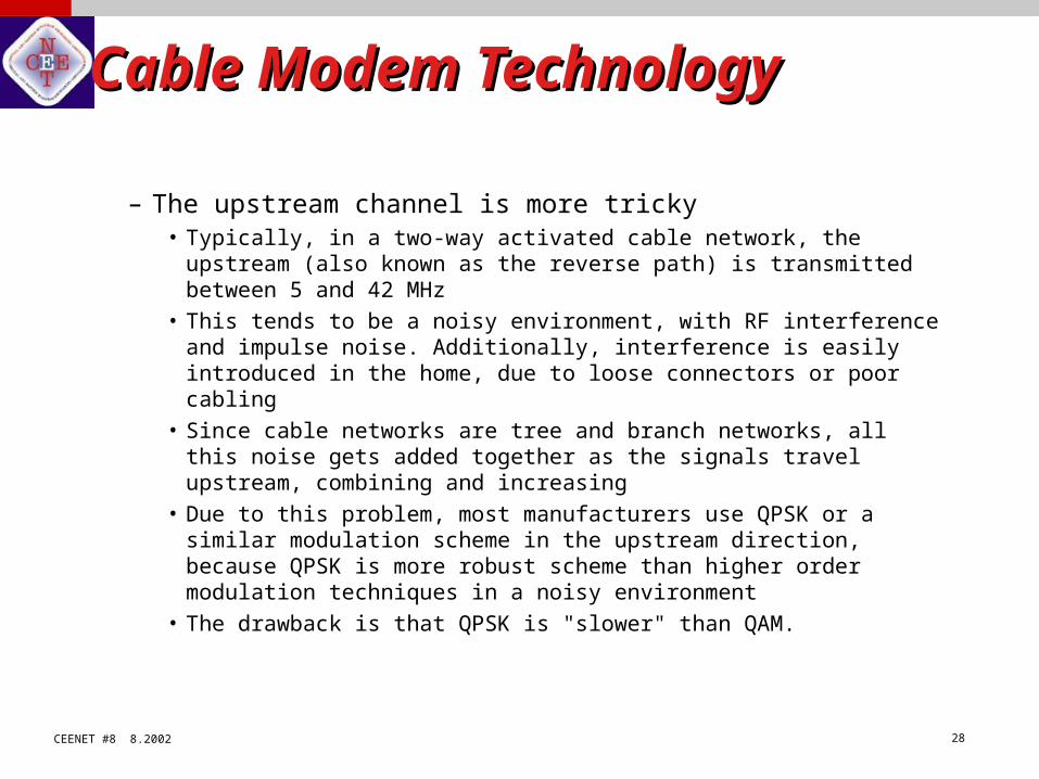
– The upstream channel is more tricky• Typically, in a two-way activated cable network, the upstream (also
known as the reverse path) is transmitted between 5 and 42 MHz
• This tends to be a noisy environment, with RF interference and impulse noise. Additionally, interference is easily introduced in the home, due to loose connectors or poor cabling
• Since cable networks are tree and branch networks, all this noise gets added together as the signals travel upstream, combining and increasing
• Due to this problem, most manufacturers use QPSK or a similar modulation scheme in the upstream direction, because QPSK is more robust scheme than higher order modulation techniques in a noisy environment
• The drawback is that QPSK is "slower" than QAM.

CEENET #8 8.2002 29
Cable Modem Services Cable Modem Services
• The dominant service is high-speed Internet access– This enables the typical array of Internet services to be
delivered at speeds far faster than those offered by dial-up telephone modems
– Other services will include
– access to streaming audio and video servers, local content (community information and services)
– access to CD-ROM servers
– a wide variety of other service offerings. New service ideas are being developed daily.

CEENET #8 8.2002 30
• In North America, cable operators are packaging high-speed data services much like they do basic cable television service
• Typically charging $40 - $60 per month for an Internet service package – Includes software, unlimited Internet access,
specialized content and rental of a cable modem
Cost of Cable Modem ServiceCost of Cable Modem Service

CEENET #8 8.2002 31
Cost of Cable Modem ServiceCost of Cable Modem Service
• At the low end of this pricing scale, a very robust Internet service is available to consumers for about the cost of a dial-up account with a local Internet service provider and a second telephone line
• Even at $60 per month, cable is a far better value than ISDN.

CEENET #8 8.2002 32
"Telco-Return" Modems"Telco-Return" Modems
• Not really a cable technology• Used more often with Direct Satellite video
systems• Satellite down link is used for fast downstream
transmission• A telephone modem handles upstream
communication over the public telephone network.
CEENET #8 8.2002 33
Support for Multiple PCsSupport for Multiple PCs
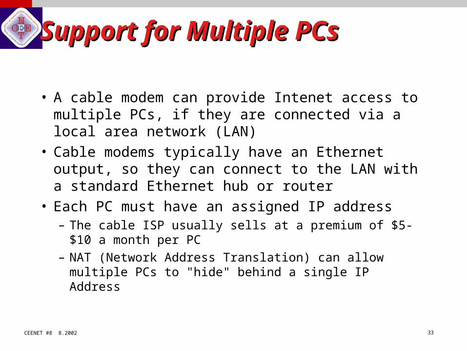
• A cable modem can provide Intenet access to multiple PCs, if they are connected via a local area network (LAN)
• Cable modems typically have an Ethernet output, so they can connect to the LAN with a standard Ethernet hub or router
• Each PC must have an assigned IP address– The cable ISP usually sells at a premium of $5-$10 a month per
PC
– NAT (Network Address Translation) can allow multiple PCs to "hide" behind a single IP Address

Cable Modems vs. ADSL
There is one major advantage that ADSL has over cable modems. Cable modems use a shared networking technology where all the cable modems share a single pipe to the Internet. This pipe speed will fluctuate depending on the number of subscribers on the network.
When ADSL is used, the pipe to the Internet is solely "yours", and is not shared along the way to a central office. This allows for a more consistent speed, and this speed does not typically fluctuate like cable modem networks.
MORE INFO... http://www.whatis.com/adsl.htm

ADSL vs. cable modem
Pro:– Secure. “Point to point
connectivity” of ADSL ensures the security of the service. Cable, by contrast, is shared media and is not secure at all.
– Bigger coverage area.– Cheap. ADSL uses
existing twisted pair, hence is cheap in installation and also cheap in monthly payment.
Cons:– Bandwidth. ADSL has
about 1.1MHz BW due to loop limitations, while cable modem has about 745MHz BW.
– Bridge taps, DLCs, load coils can lead to problems.
– Mutual noise among different DSL lines, T1 lines.

Stein Intro DSL 36
Introduction Introduction
toto
DSLDSL
Introduction Introduction
toto
DSLDSL
Yaakov J. Stein
Chief ScientistRAD Data Communications

Stein Intro DSL 37
PSTNPSTN

Stein Intro DSL 38
Original PSTNOriginal PSTN
UTP
Manual switching directly connected two local loops
Due to microphone technology, audio BW was 4 kHz
UTP

Stein Intro DSL 39
Analog switched PSTNAnalog switched PSTN
Invention of tube amplifier enabled long distance
Between central offices used FDM spaced at 4 kHz (each cable carrying 1 group = 12 channels)
Developed into hierarchical network of automatic switches(with supergroups, master groups, supermaster groups)
Stein Intro DSL 40
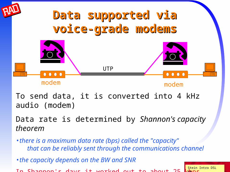
Data supported viaData supported viavoice-grade modemsvoice-grade modems
UTP
modemmodem
To send data, it is converted into 4 kHz audio (modem)
Data rate is determined by Shannon's capacity theorem
•there is a maximum data rate (bps) called the "capacity"that can be reliably sent through the communications channel
•the capacity depends on the BW and SNR
In Shannon's days it worked out to about 25 kbpstoday it is about 35 kbps (V.34 modem - 33.6 kbps)
Stein Intro DSL 41
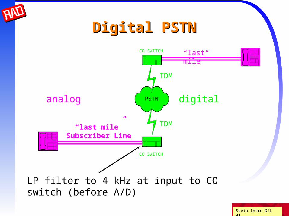
Digital PSTNDigital PSTN
“last mile”CO SWITCH
“last mile”Subscriber Line
PSTN
CO SWITCH
TDM
TDM
digitalanalog
LP filter to 4 kHz at input to CO switch (before A/D)

Stein Intro DSL 42
Digital PSTNDigital PSTNSample 4 kHz audio at 8 kHz (Nyquist) Need 8 bits per sample = 64 kbpsMultiplexing 64 kbps channels leads to higher and higher rates
Only the subscriber line (local loop) remains analog(too expensive to replace)
Can switch (cross connect) large number of channels
Noise and distortion could be eliminated due to Shannon's theorems1. Separation theorem2. Source coding theorem3. Channel capacity theorem
Stein Intro DSL 43
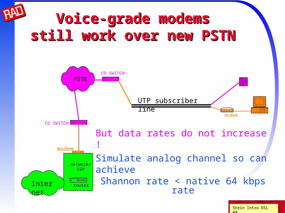
Voice-grade modemsVoice-grade modemsstill work over new PSTNstill work over new PSTN
UTP subscriber line
CO SWITCH
network/ISP
router
modem
PSTN
modem
CO SWITCH
But data rates do not increase !
Simulate analog channel so can achieve Shannon rate < native 64 kbps rate
Internet

Stein Intro DSL 44
Where is the limitationWhere is the limitation? ?
The digital network was developed incrementally
No forklift upgrades to telephones, subscriber lines, etc.
Evolutionary deployment meant that the new network needed to simulate pre-existing analog network
So a 4 kHz analog channel is presented to subscriber
The 4 kHz limitation is enforced by LP filter
at input to CO switch (before 8 kHz sampling)
The actual subscriber line is not limited to 4 kHz
Is there a better way to use the subscriber line for digital transmissions ?

Stein Intro DSL 45
UTPUTP

Stein Intro DSL 46
What is UTP?What is UTP?
The achievable data rate is limited by physics of the subscriber line
The subscriber line is an Unshielded Twisted Pair of copper wires
Two plastic insulated copper wires
Two directions over single pair
Twisted to reduce crosstalk
Supplies DC power and audio signal
Physically, UTP is – distributed resistances in series– distributed inductances in series– distributed capacitances in parallelso the attenuation increases with frequency
Various other problems exist (splices, loading coils, etc.)

Stein Intro DSL 47
UTP characteristicsUTP characteristics Resistance per unit distance
Capacitance per unit distance
Inductance per unit distance
Cross-admittance (assume pure reactive) per unit distance
R L
X
G C

Stein Intro DSL 48
UTP resistanceUTP resistance
Influenced by gauge, copper purity, temperature
Resistance is per unit distance
24 gauge 0.15 kft 26 gauge 0.195 kft
Skin effect: Resistance increases with frequency
Theoretical result R ~ f 1/2
In practice this is a good approximation

Stein Intro DSL 49
UTP capacitanceUTP capacitance
Capacitance depends on interconductor insulation
About 15.7 nF per kft
Only weakly dependent on gauge
Independent of frequency to high degree

Stein Intro DSL 50
UTP inductanceUTP inductance
Higher for higher gauge
24 gauge 0.188 mH per kft
26 gauge 0.205 mH per kft
Constant below about 10 kHz
Drops slowly above

Stein Intro DSL 51
UTP admittanceUTP admittance
Insulation good so no resistive admittance
Admittance due to capacitive and inductive coupling
Self-admittance can usually be neglected
Cross admittance causes cross-talk!

Stein Intro DSL 52
Propagation lossPropagation loss
Voltage decreases as travel along cable
Each new section of cable reduces voltage by a factor
So the decrease is exponential
Va / Vb = e - x = H(f,x)
where x is distance between points a and b
We can calculate and hence loss, directly from RCLG model
1v 1/2 v 1/4 v

Stein Intro DSL 53
Attenuation vs. frequencyAttenuation vs. frequency
0 2 4 6 8 10-90
-80
-70
-60
-50
-40
-30
-20
-10
024 and 26 AWG Cables
Freq [MHz]
Atte
nua
tion
[dB
/Km
]
24 AWG
26 AWG

Stein Intro DSL 54
Why twisted?Why twisted?
from Alexander Graham Bell’s 1881 patent
To place the direct and return lines close together.
To twist the direct and return lines around one another so that they
should be absolutely equidistant from the disturbing wires
V = (a+n) - (b+n)
n
a
b

Stein Intro DSL 55
Why twisted? - continuedWhy twisted? - continued
So don't need shielding, at least for audio (low) frequencies
But at higher frequencies UTP has cross-talk
George Cambell was the first to model (see BSTJ 14(4) Oct 1935)
Cross-talk due to capacitive and/or inductive mismatch
|I2| = Q f V1 where Q ~ (Cbc-Cbd) or Q~(Lbc-Lad)
a
d
c
b
C bc C bd
L bc L ad

Stein Intro DSL 56
Loading coilsLoading coilsLong loops have loading coils to prevent voice distortionWhat does a loading coil do?
Flattens response in voice bandAttenuates strongly above voice frequencies
loops longer than 18 kft need loading coils88 mH every 6kft starting 3kft

Stein Intro DSL 57
There may also be bridged taps
Parallel run of unterminated UTP unused piece left over from old installation placed for subscriber flexibility
High frequency signals are reflected from the open end
A bridged tap can act like a notch filter!
Bridge tapsBridge taps

Stein Intro DSL 58
Splices
Subscriber lines are seldom single runs of cableIn the US, UTP usually comes in 500 ft lengths
So splices must be made every 500 ft
Average line has >20 splices
Splices are pressure connections that add to attenuation
Over time they corrode and may spark, become intermittent, etc.
Gauge changesUS binder groups typically start off at 26 AWG
Change to 24 AWG after 10 kft
In rural areas they may change to 19 AWG after that
Other problemsOther problems

Stein Intro DSL 59
Binder groupsBinder groups
UTP are not placed under/over ground individually
In central offices they are in cable bundles with 100s of other UTP
In the outside plant they are in binder groups with 25 or 50 pairs per group
We will see that these pairs interfere with each othera phenomenon called cross-talk (XTALK)

Stein Intro DSL 60
CSA guidelinesCSA guidelines
1981 AT&T Carrier Service Area guidelines advise as follows for new deployments
No loading coils Maximum of 9 kft of 26 gauge (including bridged taps)
Maximum of 12 kft of 24 gauge (including bridged taps)
Maximum of 2.5 kft bridged taps Maximum single bridged tap 2 kft Suggested: no more than 2 gauges
In 1991 more than 60% of US lines met CSA requirements

Stein Intro DSL 61
Present US PSTNPresent US PSTN
UTP only in the last mile (subscriber line) 70% unloaded < 18kft 15% loaded > 18kft 15% optical or digital to remote terminal + DA (distribution area)
PIC, 19, 22, 24, 26 gauge
Built for 2W 4 KHz audio bandwidth
DC used for powering
Above 100KHz: severe attenuation cross-talk in binder groups (25 - 1000 UTP) lack of intermanufacturer consistency

Stein Intro DSL 62
Present US PSTN - continuedPresent US PSTN - continued
We will see, that for DSL - basically four cases
Resistance design > 18Kft loaded line - no DSL possible
Resistance design unloaded <18 Kft <1300 - ADSL
CSA reach - HDSL
DA (distribution area) 3-5 kft - VDSL
Higher rate - lower reach
(because of attenuation and noise!)

ADSL — What is it?
ADSL — Asymmetric Digital Subscriber Line – High speed communications over twisted pair.– Concurrent with POTS (plain old telephone
service).– Secure way of Internet access.– Originally standardized in ANSI (American
National Standards Institute) T1.231-1993.– Currently standardized in ANSI T1.413-1998.– Growing really fast.

9.64
ADSL is an asymmetric communication technology designed for residential
users; it is not suitable for businesses.
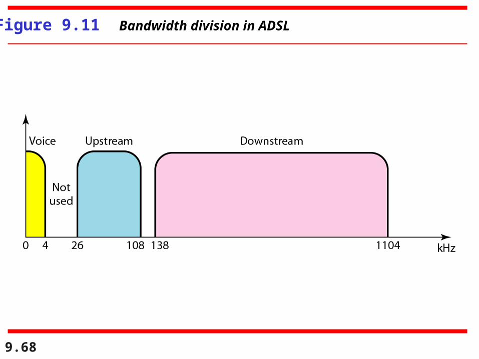
The existing local loops can handle bandwidths up to 1.1 MHz.
ADSL is an adaptive technology. The system uses a data ratebased on the condition of
the local loop line.

Stein Intro DSL 65
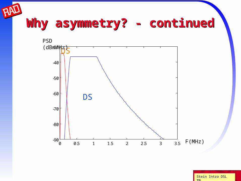
Why asymmetry?Why asymmetry?
NEXT is the worst interferer stops HDSL from achieving higher rates
FEXT much less (attenuated by line)
FDD eliminates NEXT
All modems must transmit in the SAME direction
A reversal would bring all ADSL modems down
Upstream(US) at lower frequencies and power density
Downstream (DS) at high frequencies and power

Why ADSL?
Over the past 15 years, a thousand-fold transmission rate is realized. But it still does not meet today’s need.– Viewing a full-motion movie requires about 5Mbps.– Downloading Netscape requires 10 minutes.
ADSL:– 20 fold faster

9.67
Figure 9.10 Discrete multitone technique
9.68
Figure 9.11 Bandwidth division in ADSL

9.69
Figure 9.12 ADSL modem

9.70
Figure 9.13 DSLAM

9.71
Table 9.2 Summary of DSL technologies
Stein Intro DSL 72
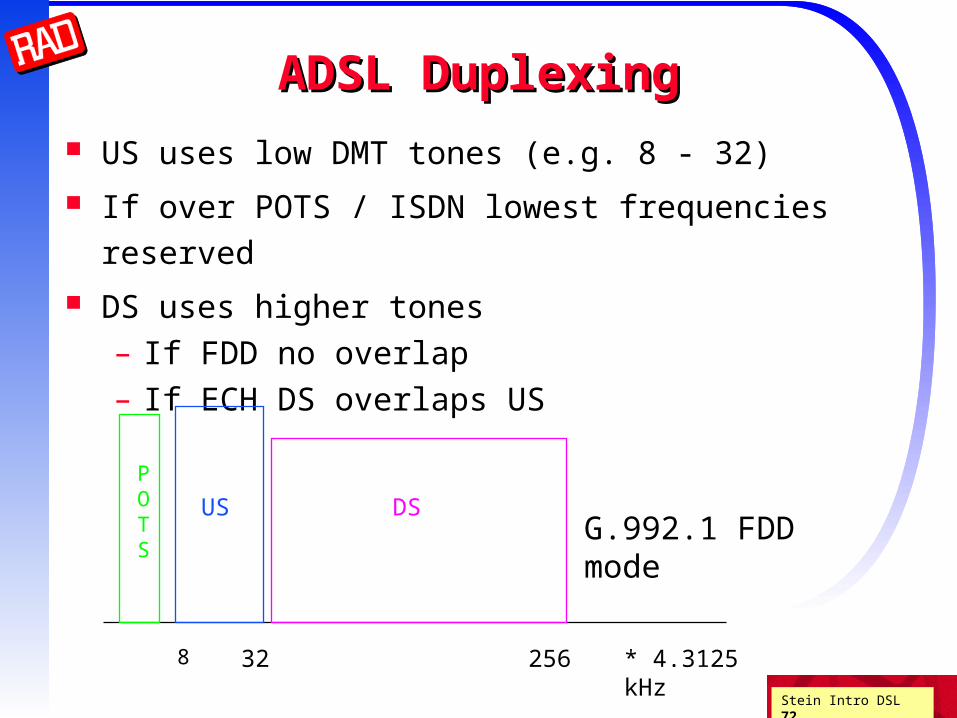
ADSL DuplexingADSL Duplexing
US uses low DMT tones (e.g. 8 - 32)
If over POTS / ISDN lowest frequencies reserved
DS uses higher tones – If FDD no overlap– If ECH DS overlaps US
POTS
US DS
8 32 256
G.992.1 FDD mode
* 4.3125 kHz
Stein Intro DSL 73
Why asymmetry? - continuedWhy asymmetry? - continued
0 0.5 1 1.5 2 2.5 3 3.5-90
-80
-70
-60
-50
-40
-30US
DS
PSD (dBm/Hz)
F(MHz)
Stein Intro DSL 74
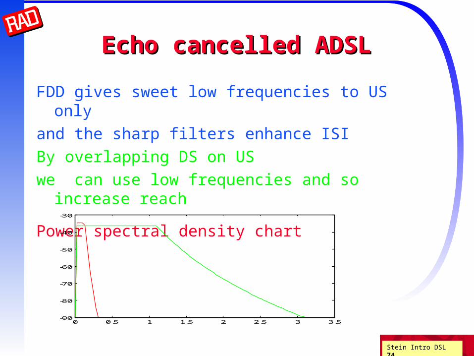
Echo cancelled ADSLEcho cancelled ADSL
FDD gives sweet low frequencies to US only
and the sharp filters enhance ISI
By overlapping DS on US
we can use low frequencies and so increase reach
Power spectral density chart
0 0.5 1 1.5 2 2.5 3 3.5-90
-80
-70
-60
-50
-40
-30
Stein Intro DSL 75
ADSL - continuedADSL - continued
ADSL system design criterion BER 10-12 (1 error every 2 days at 6 Mbps)
Raw modem can not attain this low a BER!
For video on demand: RS and interleaving can deliver (error bursts of 500 sec) but add 17 msec delay
For Internet: TCP can deliver high raw delay problematic
So the G.992.1 standard defines TWO framers
fast (noninterleaved ) and slow (interleaved) buffers

Stein Intro DSL 76
ADSL standardADSL standard
ITU (G.dmt) G.992.1, ANSI T1.413i2 standardDS - 6.144 Mbps (minimum)
US- 640 kbps
First ADSL data implementations were CAP (QAM)
ITU/ANSI/ETSI standards are DMT with spacing of 4.3125 kHz
DMT allows approaching water pouring capacity DMT is robust DMT requires more complex processing DMT may require more power

Stein Intro DSL 77
... once more...
Broadband Network (Internet)
Wiring Distribution Frame) Customer
Premises Wiring

Stein Intro DSL 78
= Assymmetric Digital Subscriber Line
- inmodulation band (not baseband)
- ANSI standards (T1.413 of T1E1.4 group), ETSI (european requirement added to T1.413), ITU (groups of standards ITU-T G.991, 992, 995 etc. – they are downloadable from : ITU - publications – ITU-T)
ADSL
Specifications:• high bit rate transmission + telephone (and also analog) connection, or ISDN • max. downstream from 1,5 to 8 Mbps / max. upstream from 16 to 832 kbps (basic ADSL system) – various data speeds in dependence from user distance• freq.band up to 1,1 MHz, DMT modulation scheme (Discrete Multitone Transmission), max. 256 DMT channels, each is 4 kHz wide• for analog teleph.- lower 4 kHz, for ISDN up to 80 kHz (if there is ISDN transmission, the band for digital data is reduced)• reach - 5,5 km• frame transmission by means Cu- lines• Full / Lite versions

Stein Intro DSL 79
Analog teleph.signal
Frequency
Fig. 1 ADSL spectrum with various variants [2]
ADSL variant
number of subchannels
from to speed number of subchannels
speedfrom to
only data
Tab.1 Comparison of ADSL variants
ISDN-BRA
Stein Intro DSL 80
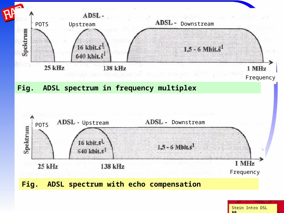
POTS Upstream Downstream
Fig. ADSL spectrum in frequency multiplex
Frequency
POTS Upstream Downstream
Frequency
Fig. ADSL spectrum with echo compensation

Stein Intro DSL 81
ADSL and ISDN
Upstream Downstream
Frequency
Frequency
Frequency
Basic Access (4B3T link code)
Basic Access (2B1Q link code)

Stein Intro DSL 82
ADSL

Stein Intro DSL 83
btw., relation between bandwidth and data speed:
Shannon-Hartley theorema for information capacity of channel with both digital signal with mean power S and additive Gauss noise with mean power N. Bandwidth of channel is B [Hz].
N
SBC 1log2 [bps] ... channel information capacity
B ... bandwidth [Hz]
S ...power of signal in the given band B [V2 or W]
N...power of noise in the given band B [V2 or W]
S/N . .. signal–to-noise ratio [-]
(we know already SNR[dB] =10 log (S/N) )

Stein Intro DSL 84
symmetrical pair
LF
HF
Fig.2 Typical termination of ADSL line on the user side
Fig.3 ADSL line configuration with splitters
user
Provider
Data network
user line
ATU-C = ADSL transceiver unit at the central office, ATU-R .....at the Remote home or business

Stein Intro DSL 85
Splitter
Stein Intro DSL 86
xDSLxDSL

Stein Intro DSL 87
Alternatives for data servicesAlternatives for data services
Fiber, coax, HFC
COST: $10k-$20k / mile
TIME: months to install
T1/E1
COST: >$5k/mile for conditioning
TIME: weeks to install
DSL
COST: 0 (just equipment price)
TIME: 0 (just setup time)

Stein Intro DSL 88
xDSLxDSL
Need higher speed digital connection to subscribers
Not feasible to replace UTP in the last mile
Older voice grade modems assume 4kHz analog line
Newer (V.90) modems assume 64kbps digital line
DSL modems don’t assume anything
Use whatever the physics of the UTP allows

Stein Intro DSL 89
xDSLxDSL System Reference Model System Reference Model
POTSSPLITTER
UTP
CO SWITCH
DSLAM
xTU-C
network/ISP
router xTU-R
POTSSPLITTER
PSTN
PDN
POTS-RPOTS-C
WAN
x = H, A, V, ...
Analog modem
frequencyDC 4 kHz
POTS xDSL

Stein Intro DSL 90
SplitterSplitter
Splitter separates POTS from DSL signals Must guarantee lifeline POTS services! Hence usually passive filter Must block impulse noise (e.g. ring) from phone into DSL
ADSLforum/T1E1.4 specified that splitter be separate from modemNo interface specification (but can buy splitter and modem from different vendors)
Splitter requires installation Costly technician visit is the major impediment to deployment ADSL has splitterless versions to facilitate residential deployment

Stein Intro DSL 91
Why is DSL better Why is DSL better than a voice-grade modem?than a voice-grade modem?
Analog telephony modems are limited to 4 KHz bandwidth
Shannon’s channel capacity theorem gives the maximum transfer rate
C = BW log2 ( SNR + 1 )
So by using more BW we can get higher transfer rates!
But what is the BW of UTP?
S
N
for SNR >> 1
C(bits/Hz) SNR(dB) / 3

Stein Intro DSL 92
Maximum reachMaximum reachTo use Shannon's capacity theorem
we need to know how much noise there is
One type of noise that is always present
(above absolute zero temperature) is thermal noise
Maximum reach is the length of cable for reliable communications
ASSUMING ONLY THERMAL NOISE
Bellcore study in residential areas (NJ) found -140 dBm / Hz white (i.e. independent of frequency)
is a good approximation
We can compute the maximum reach from known UTP attenuation

Stein Intro DSL 93
xDSL - Maximum ReachxDSL - Maximum Reach
0 10 20 30 40 50 600
1
2
3
4
5
6DSL MAXIMUM REACH
Rate[Mbps]
Re
ach
[Km
]

Stein Intro DSL 94
Other sources of noiseOther sources of noise
But real systems have other sources of noise,
and thus the SNR will be lower
and thus will have lower reach
There are three other commonly encountered types of noise
RF ingress
Near End Cross Talk (NEXT)
Far End Cross Talk (FEXT)

Stein Intro DSL 95
Sources of InterferenceSources of Interference
XMTR RCVR
RCVR XMTR FEXT
NEXT
RCVR XMTR
XMTR RCVR
RF INGRESS
THERMAL NOISE

Stein Intro DSL 96
Unger’s discoveryUnger’s discovery
What happens with multiple sources of cross-talk?
Unger (Bellcore) : 1% worst case NEXT (T1D1.3 185-244)
50 pair binders 22 gauge PIC 18 Kft
Found empirically that cross-talk only increases as N0.6
This is because extra interferers must be further away

Channel Modeling(characteristic impedance, propagation constant, channel attenuation)
)()(
)()()(
fsCfG
fsLfRsZ
)(686.8)(10ln
20),(log20),( 10 fdfdfdHfdLdB
)()()(),( fdjfdsd eeesdH

Noise
There are three main types of noise that affect
DSL system performance:
NEXT (Near End Crosstalk) FEXT (Far End Crosstalk) Impulse Noise

NEXT
When a transceiver sends a signal and a nearby transceiver at the same end “hears” the signal, it’s NEXT.
A simplified NEXT model for N disturbers:
2
3
13
6.0
10134.1
1)
49( fN
NEXTN

Stein Intro DSL 100
NEXTNEXTOnly close points are important
Distant points are twice attenuated by line attenuation |H(f,x)|2
Unger dependence on number of interferers
Frequency dependence
Transfer function ~ I2Campbell / R ~ f
2 / f 1/2
= f 3/2
Power spectrum of transmission
Total NEXT interference (noise power)
KNEXT N0.6 f 3/2 PSD(f)

FEXT
When a transceiver sends a signal and a transceiver at the far end “hears” the signal, FEXT occurs.
A simplified FEXT model for N disturbers:
226.0 )()49
( fHdfkN
FEXTN
Stein Intro DSL 102
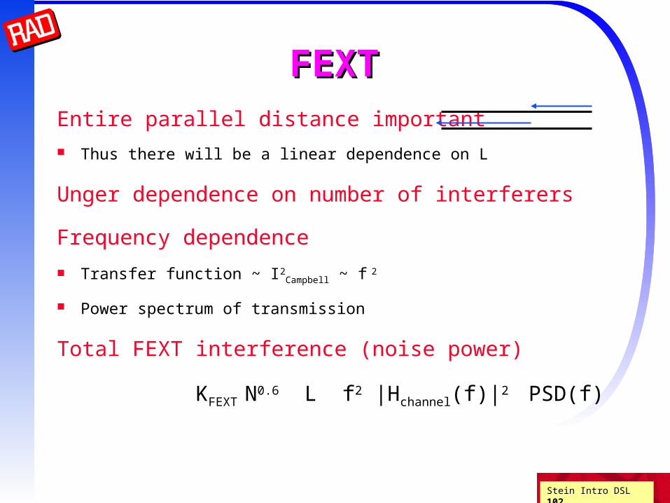
FEXTFEXT
Entire parallel distance important
Thus there will be a linear dependence on L
Unger dependence on number of interferers
Frequency dependence
Transfer function ~ I2Campbell ~ f
2
Power spectrum of transmission
Total FEXT interference (noise power)
KFEXT N0.6 L f2 |Hchannel(f)|2 PSD(f)

Impulse Noise
Impulse noises are large surges of noise with short duration. The sources of impulse noises are not well understood yet. It is a very devastating noise if not handled well.
A concatenated code, using a 2-dimensional 8-state trellis code and a 4-error-correcting Reed-Solomon code with an interleaving depth of 18 symbols, was found to be suitable for eliminating impulse noise.
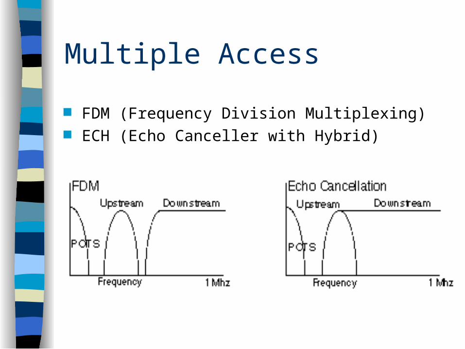
FDM (Frequency Division Multiplexing) ECH (Echo Canceller with Hybrid)
Multiple Access

Two main contenders: DMT — Discrete MultiTone
– A multi-carrier system using Discrete Fourier Transforms to create and demodulate individual carriers.
CAP — Carrierless Amplitude and Phase– A version of suppressed carrier QAM.
Line Code

DMT
Existing ANSI and ETSI standards Consists of up to 256 sub-channels, (also
called tones or bins), of 4.3125KHz– upstream use 25-163KHz (bins 6 to 38)– downstream use 142KHz-1.1MHz (bins 33 to 255)– bins 16 (69KHz) and 64 (276KHz) are pilot tones.
Outperforms CAP in field trials More expensive and complex

DMT Line Code

Observations
Three Channels: POTS channel
– POTS channel is split off from the digital modem by filters, thus guaranteeing uninterrupted POTS.
High speed downstream channel– Its data rate depends on length of the copper line,
its wire gauge, presence of bridged taps, cross talk, etc.
Medium speed upstream channel

DMT Features
Discretely divides the available frequencies into 256 sub-channels or tones.
Incoming data is broken down into a variety of bits and distributed to a specific combination of sub-channels.
To rise above noise, more data resides in the lower frequencies and less in the upper frequencies.

DMT Transmission Parameters
Downstream– symbol rate: 4KHz– FFT size: 512– Cyclic prefix: 32– Sampling rate:
2.208MHz– Transmit power:
20dBm– Highpass filter:
62.5kHz
Upstream– Symbol rate: 4kHz– FFT size: 64– Cyclic prefix: 4– Sampling rate:
276kHz– Transmit
Power:7dBm– Lowpass filter:
43.875kHz

DMT Block Diagram
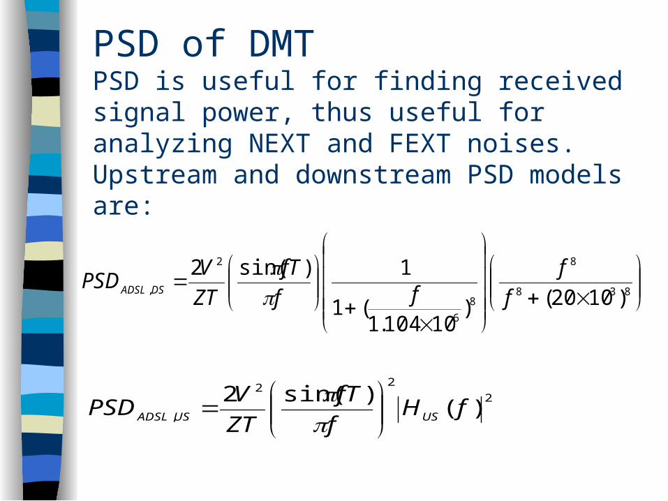
PSD of DMTPSD is useful for finding received signal power, thus useful for analyzing NEXT and FEXT noises.Upstream and downstream PSD models are:
838
8
8
6
2
, )1020()10104.1
(1
1)sin(2
f
fff
fT
ZT
VPSD DSADSL
2
22
, )()sin(2
fHf
fT
ZT
VPSD USUSADSL
Stein Intro xDSL 3.113
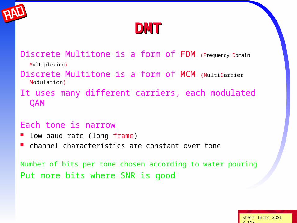
DMTDMT
Discrete Multitone is a form of FDM (Frequency Domain
Multiplexing)
Discrete Multitone is a form of MCM (MultiCarrier Modulation)
It uses many different carriers, each modulated QAM
Each tone is narrow low baud rate (long frame) channel characteristics are constant over tone
Number of bits per tone chosen according to water pouring
Put more bits where SNR is good
Stein Intro xDSL 3.114
DMT - continuedDMT - continued
DMT is OFDM (Orthogonalized FDM) Carrier spacing is precisely baud rate Center of tone is precisely the zero of all other sincs ICI minimized
ISI minimized by having a long interframe guard time
DMT modem can be efficiently implemented using FFT DFT is mathematically equivalent to a bank of filters
Filtering is equivalent to cyclic convolution
So use cyclic prefix rather than guard time

Stein Intro xDSL 3.115
DMT - continuedDMT - continued
time
frequency

Stein Intro xDSL 3.116
ADSL DMTADSL DMT
Baud rate (and channel spacing) is 4.3125 KHz
US uses tones 8 - 32 (below 30 KHz reserved)
DS uses 256 tones (FDM from tone 33, EC from tone 8)
POTS
US DS
8 32 256
Stein Intro xDSL 3.117
DMT misc.DMT misc.
bit handling ((de)framer, CRC, (de)scrambler, RS, (de)interleaver)
tone handling (bit load, gain scaling, tone ordering, bit swapping)
QAM modem (symbolizer, slicer)
signal handling (cyclic prefix insertion/deletion, (I)FFT, interpolation, PAR reduction)
synchronization (clock recovery)
channel handling (probing and training, echo cancelling, FEQ, TEQ)

Stein Intro DSL 118
Splitterless ADSLSplitterless ADSL
Splitterless ADSL, UAWG, G.lite, G.992.2, G.992.4
Splitterless operation fast retrain power management to eliminate clipping initialization includes probing telephone sets for power level microfilters modems usually store environment parameters
G.992.2 - cost reduction features G.992.1 compatible DMT compatible using only 128 tones 512 Kbps US / 1.5 Mbps DS (still >> V.34 or V.90 modems) features removed for simplicity simpler implementation (only 500 MIPS < 2000 MIPS for full rate)

Frame Structure

Frame Structure (cont.)
A super frame is defined for every 68 IFFT/FFT
operations.The super frame has a time duration
of 68/4k=17ms for baud rate of 4kHz.
CAP
Initial ADSL implementations were done using CAP
1996 - 90% of world-wide ADSL implementation based on CAP
Variant of QAM - widely understood Not yet incorporated in ANSI standards
T1.413 or ETSI Supported by GlobeSpan Technologies

CAP Transmission Parameters
Downstream– Constellation size: 64– Baud rate: 266.67KHz– Throughput: 1.6 Mbps– Sampling
rate:1.0667MHz– Transmit power: 12dBm– Signal spectrum:
170 ~ 410KHz
Upstream– Constellation size: 16– Baud rate: 6KHz– Throughput: 24Kbps– Transmit power:-
4.8dBm– Signal spectrum:
96 ~ 102KHz
Stein Intro DSL 123
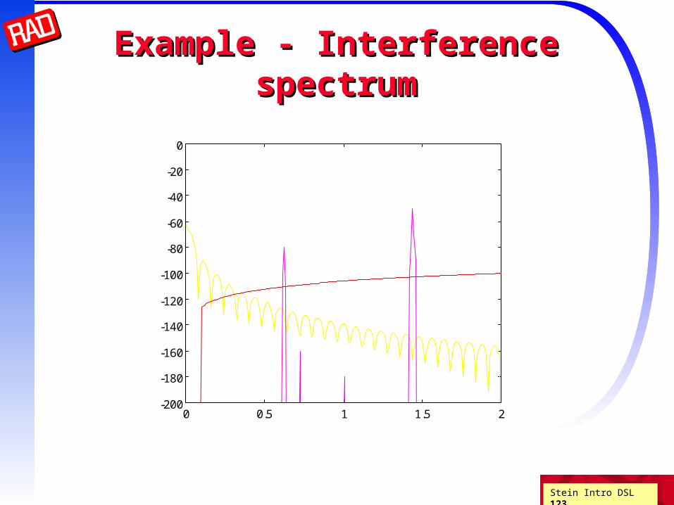
Example - Interference spectrumExample - Interference spectrum
0 0.5 1 1.5 2-200
-180
-160
-140
-120
-100
-80
-60
-40
-20
0ISDN NEXT, AM INGRESS, SELF FEXT
Freq [MHz]
Inte
rfe
renc
e [d
Bm
/Hz]

Stein Intro DSL 124
Examples of Realistic ReachExamples of Realistic Reach
More realistic design goals (splices, some xtalk)
1.5 Mbps 18 Kft 5.5 km (80% US loops)
2 Mbps 16 Kft 5 km
6 Mbps 12 Kft 3.5 km (CSA 50% US loops)
10 Mbps 7 Kft 2 km
13 Mbps 4.5 Kft 1.4 km
26 Mbps 3 Kft 900 m
52 Mbps 1 Kft 300 m (SONET STS-1 = 1/3 STM-1)

Stein Intro DSL 125
ISDN
ADSL
FTTx, VDSL2,ADSL2plus
EnhancedCopper
Hybrid Fibre/Copper
Pure Fibre
ADSL Speed ComparisonADSL Speed Comparison
Voice bandModem
FTTH

Stein Intro DSL 126
ADSL RangeADSL RangeoIn general, the maximum range for DSL without a repeater
is 5.5 km oAs distance decreases toward the telephone company
office, the data rate increases
For larger distances, you may be able to have DSL if your phone company has extended the local loop with optical fiber cable
Data Rate Wire gauge Wire size Distance
1.5 or 2 Mbps 24 AWG 0.5 mm 5.5 km
1.5 or 2 Mbps 26 AWG 0.4 mm 4.6 km
6.1 Mbps 24 AWG 0.5 mm 3.7 km
1.5 or 2 Mbps 26 AWG 0.4 mm 2.7

Stein Intro DSL 127
ADSL Speed FactorsADSL Speed Factors
The distance from the local exchange
The type and thickness of wires used
The number and type of joins in the wire
The proximity of the wire to other wires carrying ADSL, ISDN and other non-voice signals
The proximity of the wires to radio transmitters.
Stein Intro DSL 128
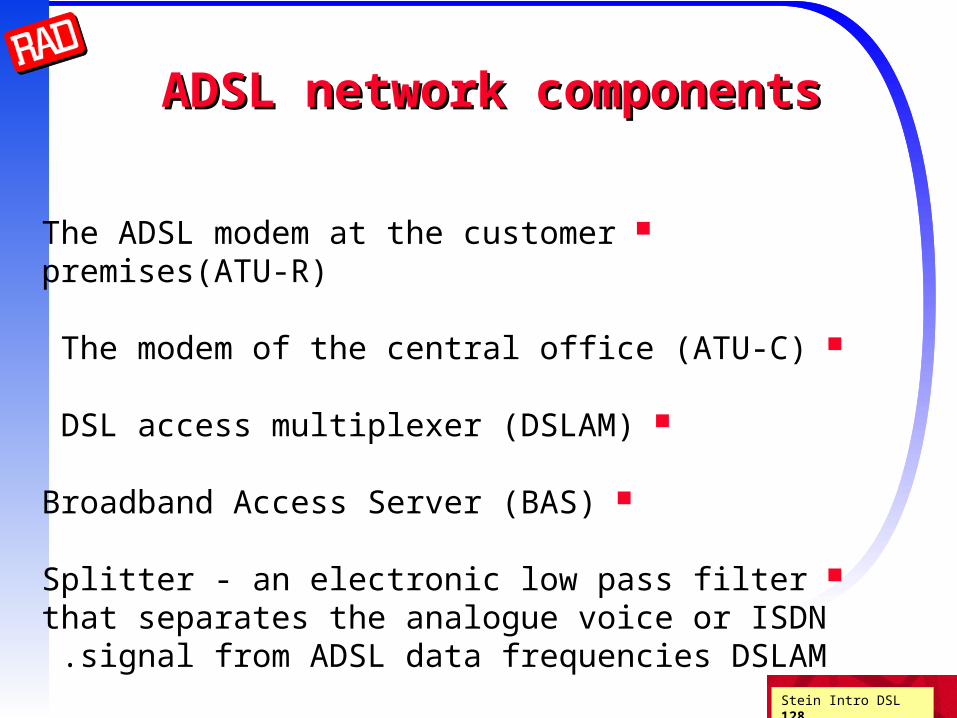
ADSL network componentsADSL network components
The ADSL modem at the customer premises(ATU-R)
The modem of the central office (ATU-C)
DSL access multiplexer (DSLAM)
Broadband Access Server (BAS)
Splitter - an electronic low pass filter that separates the analogue voice or ISDN signal from ADSL data frequencies DSLAM .

Stein Intro DSL 129
Bonding (inverse mux)Bonding (inverse mux)
If we need more BW than attainable by Shannon bounds
we can use more than one UTP pair (although XT may reduce)
This is called bonding or inverse multiplexing
There are many ways of using multiple pairs: ATM - extension of IMA (may be different rates per pair)
ATM cells marked with SID and sent on any pair Ethernet - based on 802.3(EFM) frames are fragmented, marked with SN, and sent on many pairs Time division inverse mux Dynamic Spectral Management (Cioffi) Ethernet link aggregation

Stein Intro DSL 130
DuplexingDuplexingUp to now we assumed that only one side transmits
Bidirectional (full duplex) transmission requires some form of duplexing
For asymmetric applications we usually speak ofDS downstream and US upstream
Four methods are in common use: Half duplex mode (4W mode) (as in E1/T1)
Echo cancellation mode (ECH) Time Domain Duplexing (requires syncing all binder contents)
Frequency Domain Duplexing
frequencyDC 4 kHz
POTS US DS

Stein Intro DSL 131
Muxing, inverse muxing, duplexingMuxing, inverse muxing, duplexing
Duplexing = 2 data streams in 2 directions on 1 physical line
Multiplexing = N data streams in 1 direction on 1 physical line
Inverse multiplexing = 1 data stream in 1 direction on N physical lines
data streams physical line
multiplexing
data stream physical lines
inverse multiplexing
duplexing

Stein Intro DSL 132
(Adaptive) echo cancellation(Adaptive) echo cancellation
Signal transmitted is known to transmitter
It is delayed, attenuated and distorted in the round-trip
Using adaptive DSP algorithms we can find the delay/attenuation/distortion subtract
modulator
demodulator
4W to 2W
HYBRID
Stein Intro DSL 133
xDSL types xDSL types and and
historyhistory
Stein Intro DSL 134
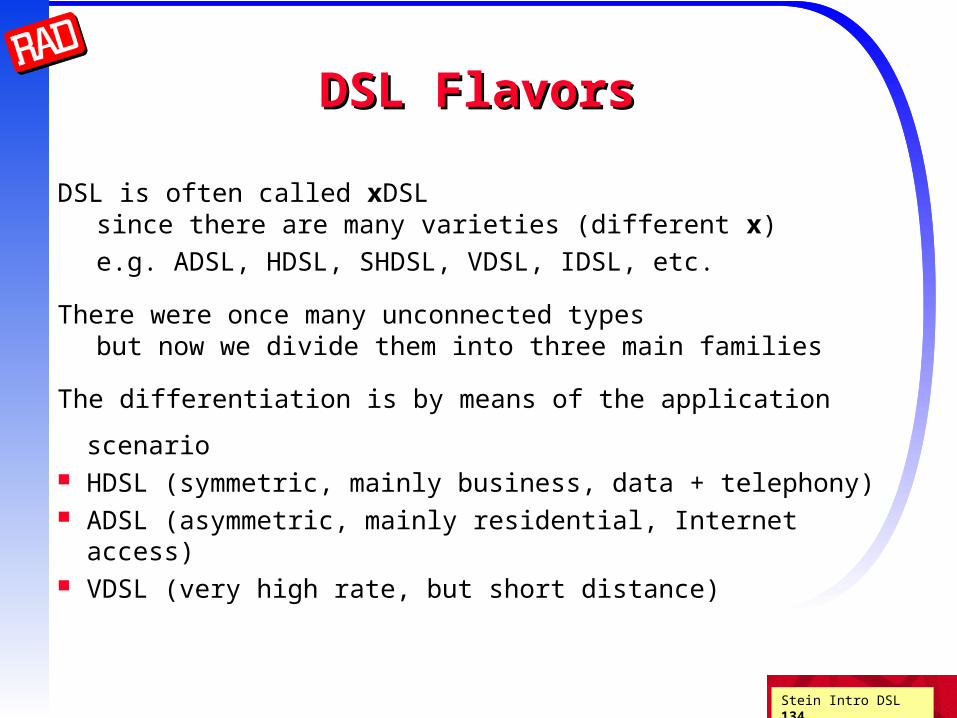
DSL FlavorsDSL Flavors
DSL is often called xDSLsince there are many varieties (different x)
e.g. ADSL, HDSL, SHDSL, VDSL, IDSL, etc.
There were once many unconnected typesbut now we divide them into three main families
The differentiation is by means of the application scenario HDSL (symmetric, mainly business, data + telephony) ADSL (asymmetric, mainly residential, Internet access) VDSL (very high rate, but short distance)

Stein Intro DSL 135
Some xDSL PSDsSome xDSL PSDs
0 0.5 1 1.5 2 2.5 3 3.5-90
-80
-70
-60
-50
-40
-30
F(MHz)
PSD(dBm/Hz)
IDSLT1
HDSL HDSL2
ADSL
Stein Intro DSL 136
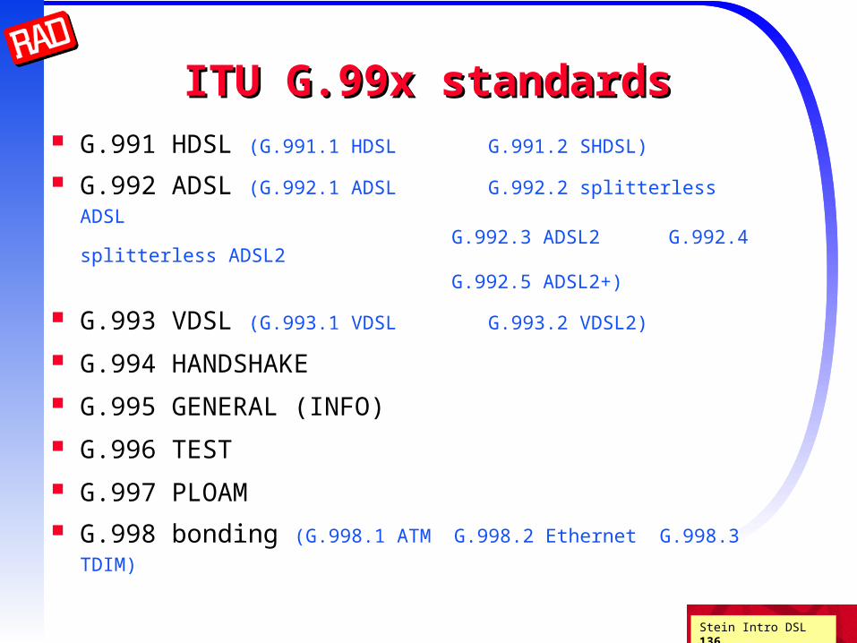
ITU G.99x standardsITU G.99x standards G.991 HDSL (G.991.1 HDSL G.991.2 SHDSL)
G.992 ADSL (G.992.1 ADSL G.992.2 splitterless ADSL G.992.3 ADSL2 G.992.4 splitterless ADSL2 G.992.5 ADSL2+) G.993 VDSL (G.993.1 VDSL G.993.2 VDSL2)
G.994 HANDSHAKE
G.995 GENERAL (INFO)
G.996 TEST
G.997 PLOAM G.998 bonding (G.998.1 ATM G.998.2 Ethernet G.998.3 TDIM)

Stein Intro DSL 137
ITU xDSL layer modelITU xDSL layer model
Transport protocol (ATM, STM, PTM)
Transport Protocol Specific - Transmission Convergence (TPS-TC)
Physical Medium Specific - Transmission Convergence (PMS-TC)
Physical Medium Dependent (PMD)
Physical medium

Stein Intro DSL 138
More xDSL flavorsMore xDSL flavors
modem speed reach main applications
IDSL 160 (144) Kbps 5.5 km POTS replacement, videoconferencing, Internet access
HDSL 2 Mbps (4-6W) 3.6-4.5 km T1/E1 replacement PBX interconnect, FR
HDSL2 2 Mbps (2W) 3 km same as HDSL
SHDSL 2.3 Mbps 3 km same as HDSL
SHDSLbis 4.6 Mbps 3 km same as HDSL

Stein Intro DSL 139
More xDSL flavors (cont.)More xDSL flavors (cont.)
modem speed reach main applications
ADSL 6 Mbps DS 640 Kbps US
3.5-5.5 km residential Internet, video-on-demand
ADSL2 8 Mbps DS 800 Kbps US
> ADSL Internet access, VoIP
ADSL2+ 16 Mbps DS 800 Kbps US
< 2 km “
VDSL <= 52 Mbps 300m - 1 km LAN interconnect, HDTV, combined services
VDSL2 200 Mbps (aggregate)
up to 1.8 km “
cable modem 10-30Mbps DS shared
50 km residential Internet
HPNA 1, 10 Mbps home wiring residential networking
Not DSL

Stein Intro DSL 140
HDSL2HDSL2
With the success of HDSL, customers requested HDSL service that would : require only a single UTP HDSL attain at least full CSA reach be spectrally compatible w/ HDSL, T1, ADSL, etc.
The result, based on high order PAM, was called HDSL2 (ANSI) SDSL Symmetric DSL (ETSI)
and is now called SHDSL Single pair HDSL (ITU)

Stein Intro DSL 141
SHDSLSHDSL
Uses Trellis Coded 16-PAM with various shaping options
Does not co-exist with POTS service on UTP
Can uses regenerators for extended reach
single-pair operation 192 kbps to 2.312 Mbps in steps of 8 kbps 2.3 Mbps should be achieved for reaches up to 3.5 km
dual-pair operation (4-wire mode) 384 kbps to 4.608 Mbps in steps of 16 kbps line rate is the same on both pairs
Latest standard (G.shdsl.bis - G.991.2 2003 version) bonding up to 4 pairs rates up to 5696 kbps optional 32-PAM (instead of 16-PAM) dynamic rate repartitioning

Stein Intro DSL 142
ADSLADSL
Asymmetric - high rate DS, lower rate US
Originally designed for video on demand
New modulation type - Discrete MultiTone
FDD and ECH modes
Almost retired due to lack of interest
…but then came the Internet
Studies - DS:US for both applications can be about 10:1
Some say ADSL could mean All Data Subscribers Living
Stein Intro DSL 143
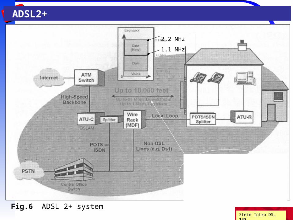
Fig.6 ADSL 2+ system
2,2 MHz
1,1 MHz
Up to 18,000 feet (5.5 km)
Up to 25 Mbps down
Up to 1 Mbps Upstream
ADSL2+

Stein Intro DSL 144
ADSL2
- ITU-T G. 992.3, .4
- 2nd generation of ADSL standard
- downstream - up to 12 Mbps
- DMT modulation
- bandwidth - up to 2,2 MHz
- but: shorter reach (only from 1,5 to 2 km) !
- CVoDSL
ADSL2 + (fig.6)
- ITU-T G. 992.5
- downstream - up 24 Mbps
- bandwidth - up to 2,2 MHz (512 subchannels DMT, each 4kHz wide, up to 2,2 MHz)
- full data speed only in reach of max. 1,5 km from DSLAM (!)
Stein Intro DSL 145
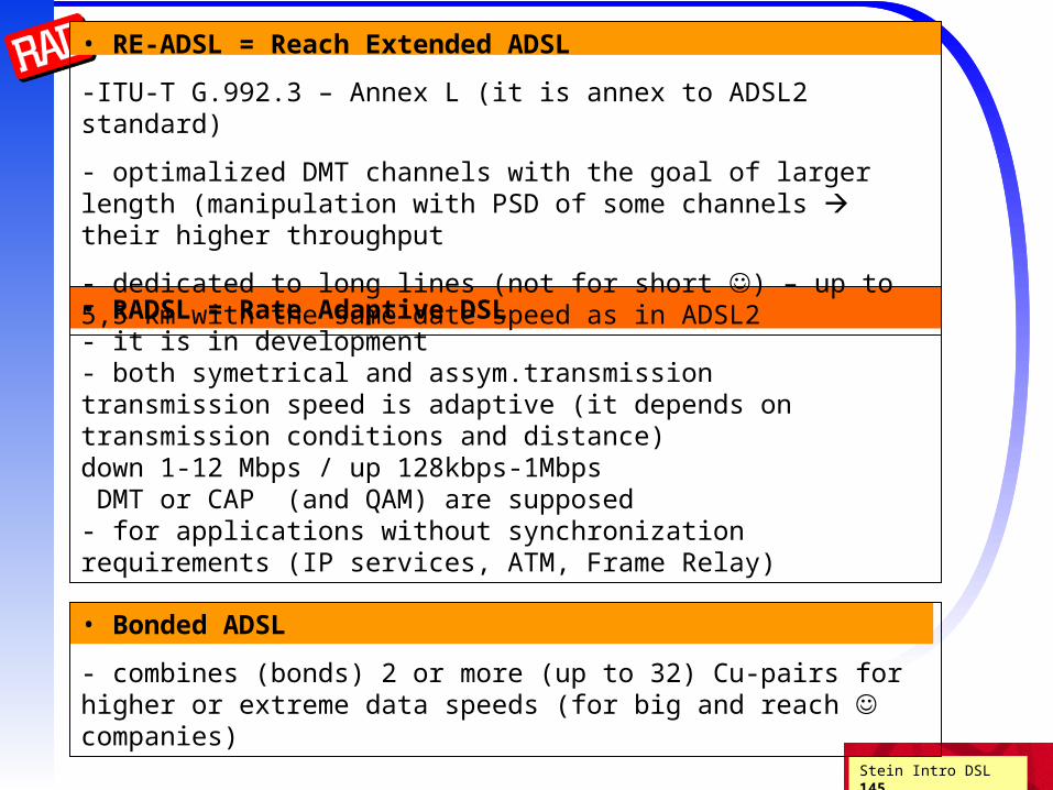
• RE-ADSL = Reach Extended ADSL
-ITU-T G.992.3 – Annex L (it is annex to ADSL2 standard)
- optimalized DMT channels with the goal of larger length (manipulation with PSD of some channels their higher throughput
- dedicated to long lines (not for short ) – up to 5,5 km with the same date speed as in ADSL2
• RADSL = Rate Adaptive DSL- it is in development- both symetrical and assym.transmissiontransmission speed is adaptive (it depends on transmission conditions and distance)down 1-12 Mbps / up 128kbps-1Mbps DMT or CAP (and QAM) are supposed- for applications without synchronization requirements (IP services, ATM, Frame Relay)
• Bonded ADSL
- combines (bonds) 2 or more (up to 32) Cu-pairs for higher or extreme data speeds (for big and reach companies)

Stein Intro DSL 146
ADSL2ADSL2
ADSL uses BW from 20 kHz to 1.1 MHz
ADSL2 Increases rate/reach of ADSL by using 20 kHz - 4.4 MHz
Also numerous efficiency improvements better modulation reduced framing overhead more flexible format (see next slide) stronger FEC reduced power mode misc. algorithmic improvements
for given rate, reach improved by 200 m
3 user data types - STM, ATM and packet (Ethernet)
ADSL2+ dramatically increased rate at short distances

Stein Intro DSL 147
More ADSL2 featuresMore ADSL2 features
Dynamic training features
Bit Swapping (dynamic change of DMT bin bit/power allocations)
Seamless Rate Adaptation (dynamic change of overall rate)
Frame bearers
Multiple (up to 4) frame bearers (data flows)
Multiple latencies for different frame bearers (FEC/interleave lengths)
Dynamic rate repartitioning (between different latencies)
Stein Intro DSL 148
VDSLVDSL
Optical network expanding (getting closer to subscriber)
Optical Network Unit ONU at curb or basement cabinet
FTTC (curb), FTTB (building)
These scenarios usually dictates low power
Rates can be very high since required reach is minimal!
Proposed standard has multiple rates and reaches

Stein Intro DSL 149
VDSL - rate goalsVDSL - rate goals
Symmetric rates 6.5 4.5Kft (1.4 Km)
13 3 Kft (900 m)
26 1 Kft (300 m)
Asymmetric rates (US/DS)0.8/ 6.5 6 Kft (1.8 Km)
1.6/13 4.5 Kft (1.4Km)
3.2/26 3 Kft (900 m)
6.4/52 1 Kft (300 m)
Stein Intro DSL 150
VDSL - Power issuesVDSL - Power issues
Basic template is -60 dBm/Hz from 1.1MHz to 20 MHz
Notches reduce certain frequencies to -80 dBm/Hz
Power boost on increase power to -50 dBm/Hz
Power back-off reduces VTU-R power so that won’t block another user
ADSL compatibility off use spectrum down to 300 KHz

Stein Intro xDSL 3.151
VDSL - duplexingVDSL - duplexing
In Japan and campus applications can operate TDD (ping pong)
SDMT Synchronous DMT (2 KHz frame can be heard in adjacent pairs or hearing aids)
Rest of world PSTN only FDD is allowed
Can divide US and DS into 2 areas (e.g. ADSL) or more
Need guard frequencies because of clock master/slave problems
Zipper - large number of interleaved frequency regions
(even on a bin by bin basis)

Stein Intro xDSL 3.152
VDSL line code warsVDSL line code wars
VDSL Alliance VDSL Coalition
DMT QAM
MORE LESS
robust to noise power
capacity complex
spectral compatibility expensive
IPR A/D bits
With no complexity constraints probably equivalent
Stein Intro DSL 153
VDSL2VDSL2
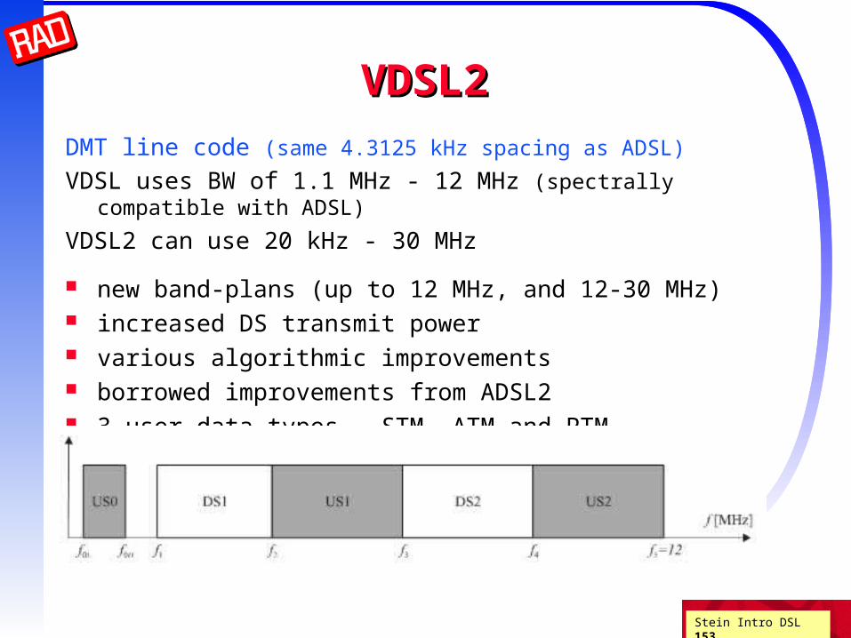
DMT line code (same 4.3125 kHz spacing as ADSL)
VDSL uses BW of 1.1 MHz - 12 MHz (spectrally compatible with ADSL)
VDSL2 can use 20 kHz - 30 MHz
new band-plans (up to 12 MHz, and 12-30 MHz) increased DS transmit power various algorithmic improvements borrowed improvements from ADSL2 3 user data types - STM, ATM and PTM
Stein Intro DSL 154
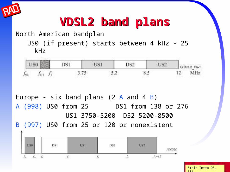
VDSL2 band plansVDSL2 band plansNorth American bandplan
US0 (if present) starts between 4 kHz - 25 kHz
and ends between 138-276 kHz
Europe - six band plans (2 A and 4 B)
A (998) US0 from 25 DS1 from 138 or 276
US1 3750-5200 DS2 5200-8500
B (997) US0 from 25 or 120 or nonexistent
DS1 from 138 or 276
US1 3000-5100 DS2 5100-7050