guy cable design and damping for vertical axis wind...
TRANSCRIPT

SAND80-2669
Unlimited ReleaseUC-60
;
Guy Cable Design and Damping forVertical Axis Wind Turbines
Thomas G. Carrie
o)

. . . ,,,, . . . . ..- L
Issued by Sand@ National ,Laboratories, operated for the United States Department ofEnergy by Sand,. Corporatmn.
Printed in the United States of America
Available from:
National Technical Information ServiceU. S. Department of Commerce5285 Port Royal RoadSpringfield, VA 22161
NTIS Price Codes:
Printed Copy $6.00; Microfiche: AO3

SAND80-2669
GUY CABLE DESIGN AND DAMPING FOR VERTICAL AXIS WIND TURBINES.
Thomas G. CarrieSandia National Laboratories
Division 5523Albuquerque, New Mexico 87185
ABSTRACT
Guy cables are frequently used to support vertical axis windturbines since guying the turbine reduces some of thestructural requirements on the tower. The guys must bedesigned to provide both the required strength and the requiredstiffness at the top of the turbine. The axial load which theguys apply to the tower, bearings, and foundations is anundesirable consequence of using guys to support the turbine.Limiting the axial load so that it does not significantlyaffect the cost of the turbine is an important objective of thecable design. The lateral vibration of the cables is anotherfeature of the cable design which needs to be considered.These aspects of the cable design are discussed in this paper,and a technique for damping cable vibrations is mathematicallyanalyzed and demonstrated with experimental data.
* This work was supported by the U. S. Department of EnergyContract DE-AC094-76DPO0789.
** A U. S. Department of Energy Facility

TABLE OF CONTENTS
PageIntroduction. . . . . . . . . . . . . . . . . . . . . . . 6Design Guidelines . . . . . . . . . . . .
. . . . ● m., 7
Cable Vibrations. . . . . . . . . . . . .. . . . .,., 12
Conclusions . . . . . . . . . . . . . . . . . . . . . . . 25
Acknowledgements. . . . . . . . . . . .. . . . .*,. . 25 v
References. . . . . . . . . . . . . . . . . ..O . . . . 25
ILLUSTRATIONS
FigureI
Page
1
2
3
4
5
6
7
8
9
10
11
Modal Frequencies Versus Cable Stiffness,K=4440 lbs\in, speed = 48.1 rpm.
Diagram of Cable Damping Concept
Diagram of Cable with Damper
-
9
13
14
The Variation in Damping Factor withViscous Damping Coefficient
17
CableSpeed
CableSpeed
CableSpeed
CableSpeed
CableSpeed
CableSpeed
Horizontal Acceleration Versus Windfor Tension 1, Undamped
21
Horizontal Acceleration Versus Windfor Tension 2, Undamped
21
Horizontal Acceleration Versus Windfor Tension 2, Damped
21
Horizontal Acceleration Versus Windfor Tension 3, Undamped
22
Horizontal Acceleration Versus Windfor Tension 3, Damped
22
Vertical Acceleration Versus Windfor Tension 1, Undamped
23
Vertical Acceleration Versus Windfor Tension 2, Undamped
?2
CableSpeed
..

ILLUSTRATIONS (Cont.)
Figure—
12 Cable Vertical Acceleration Versus WindSpeed for ‘Tension 2, Damped
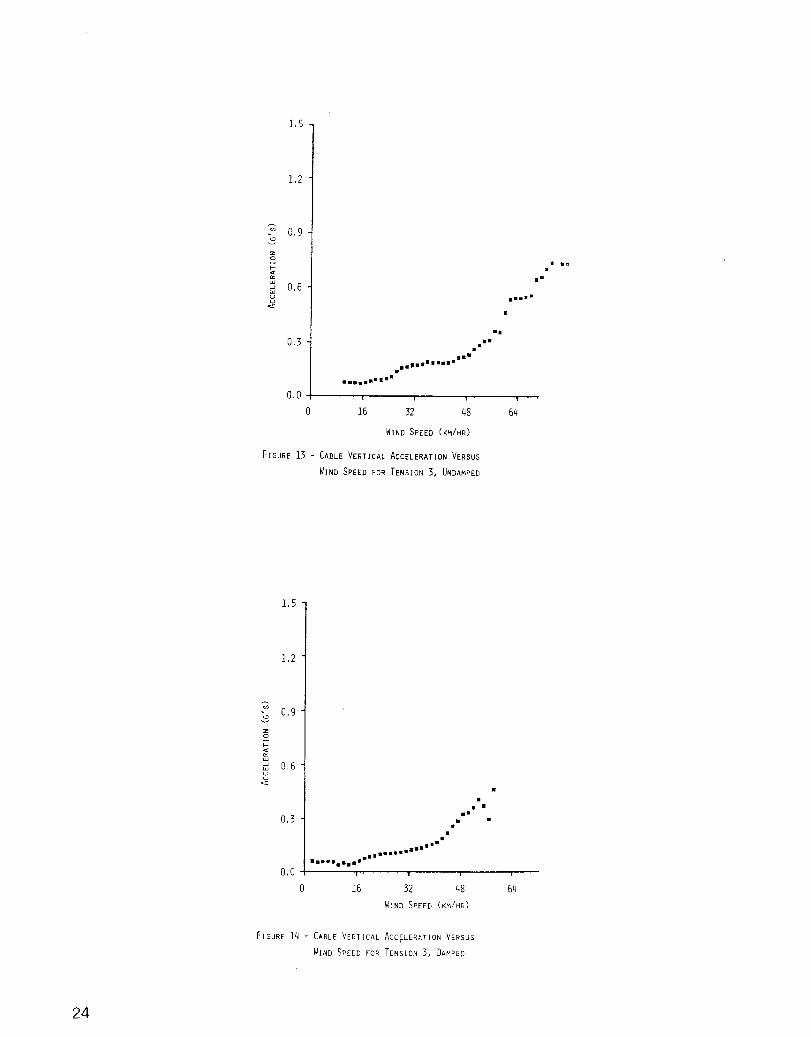
13 Cable Vertical Acceleration Versus WindSpeed for Tension 3, Undamped
14 Cable Vertical Acceleration Versus WindSpeed for Tension 3, Damped
Page
23
24
24

Introduction
Most vertical axis wind turbines use guy cables to support the
top of a single, fully rotating central tower. Other”designs,
such as a cantilevered tower or two concentric towers (one
stationary to react cable loads) have been found to be,
generally, less cost effective. The guy cables serve two
primary functions while supporting the turbine. They provide
the strength necessary to hold the turbine during hurricane
winds, and they provide the stiffness at the top of the rotor.
The strength and stiffness requirements are not competing
design objectives, however, one or the other may “drive” the
various parameters involved in the cable design.
There are two important consequences of using guy cables to
support the rotor. First, since guys have an initial tension,
the vertical component of the tension is reacted through the
tower, the foundation and, in this case, the bearings. This
axial load imposed by the guys impacts the cost of these
components. The second consequence of the guy support is
lateral vibrations of the cables. Cable vibration will be
excited by the motion of the top of the turbine while it is
operating. There is always excitation to the cables as long as
the turbine is operating in wind. If the excitation frequency
is near one of the cable natural frequencies, then the
amplitude of vibration can be quite large. Large amplitude
cable vibrations need to be avoided in order to reduce fatigue

in the cables and their terminations and also to maintain a
reasonable blade/cable clearance distance. Other aspects of
the cable design, which include the cable sag, the required
blade/cable clearance distance, thermal expansion effects, and
cable anchors, are discussed in some detail in Ref. 1-5.
Design Guidelines
There are a number of cable parameters which have to be
chosen in order to establish the design for the guys. These
parameters a~e the cross-sectional area of a cable, the number
of cables, the length of the cables, the pretension of the
cables, the cable elevation angle, and the cable material
(density and modulus). All of these parameters affect the two
key design requirements on the guys, their support strength and
the stiffness they create at the top of the turbine [Ref. 3].
These cable parameters also affect the consequences of the
cable design which include lateral cable vibrations, cable sag,
and the resulting axial load on the turbine due to the tension
in the guys [Ref. 3].
The strength requirement on the guys is the easiest to
specify. The cross-sectional area of the cables must be
sufficiently large to support the turbine during parked
survival in hurricane winds without the tension in the cables
exceeding their ultimate strength divided by a factor of
safety. A factor of safety of at least three is recommended
for cables with an expected life of thirty years. This factor

of safety is not conservative when compared to other cable
applications and should be increased if the turbine will be
placed in an environment which is particularly harsh for
corrosion. The tension in cables during the parked survival
condition will be the initial tension plus the increase (or
decrease) due to the wind drag on the turbine. Thus the value
of the initial tension will affect the cable tension during
parked survival unless the initial tension is suf~iciently lnw
that the downwind cable goes slack during the hurricane winds.
The stiffness requirement for the guys is impossible to
generalize for all turbine,designs. The required stiffness
will have to be chosen interactively with the rest of the
turbine design. This is due to the fact that the stiffness at
the top of the turbine affects the frequencies of the natural
modes of vibration. However, these frequencies are also
controlled by the whole turbine structure especially the blades
and the tower. Consequently, depending on the desirable values
for these modal frequencies, the operational frequency of the
turbine, and the structural properties of the turbine, the guy
cable stiffness will have to be chosen accordingly.
Figure 1 shows the variation in the modal frequencies with
the guy stiffness for the 17-Meter Low Cost Turbine. Examining
this figure, one can see that some of the modes are quite
sensitive to the guy stiffness. Further, we can see that, in
order to keep the modal frequencies away from the excitation
frequencies, the guy stiffness is forced to be greater than
three k.
8

2nd Eiymm Blade ~
I4.0
1
.
N
~ 3.O\rev -9 .— - .—. —- .— i-— — —- .— .— -
2.0
j ---------- ,--”--
1 o/rO~r - ——. —.’
E
A. L.. ”
III
I/
+I?rope ler I
~Butterfly !1 . .
k/32 k/16-.
k/8 k/4 k/2 k 2k 4k -k
CABLE STIFFNESS
FIGUREI - IIODALFREQUENCIESVERSUSCABLE STIFFNESS
K = 4440 LBS/lN, SPEED = 48,1 RPM

Another consideration for choosing the cable stiffness is
the allowable angle change for the bearings at the bottom of
the rotor. If the bearing can only allow a small angle change
of the rotor, then the cable stiffness will have to be
sufficiently high to restrain the rotor from leaning. However,
if a universal joint is used to protect the bearing or some
more tolerant bearing design is used, then this constraint on
the stiffness will not apply.
The frequencies of lateral vibrations of the guy cables are
a consequence of the guy design, and they can place a
constraint on the design. The natural frequencies of vibration
of the cables are fn = n(T/pA)%/2L [Ref. 3] where n is the
mode number, L is the cable length, T is the guy tension, A is
the cable cross-sectional area, and P is the mass density. In
many designs these parameters cannot be chosen so that the
first cable frequency is above the excitation frequency of
2.O/rev (for a two bladed turbine) since that would force the
tension to be larger than would otherwise be desirable.
Further, since the tensions in the cables vary with the wind
velocity and temperature, it may not be possible to completely
avoid all cable resonances in any case. The cable vibration
problem is discussed in the last section of this paper and a
technique for restraining the vibrations is analyzed and
demonstrated.
The sag of the guy cables is another consequence of the guy
design, and it must be evaluated and compared with the
10

bl,ades/cable clearance distance. If the sag is too large for
available clearance, then the cable design will have to be
changed. More discussion of the clearance requirements can be
foupd in Ref. 3.
The axial load which is applied to the turbine by the guys
can be the most serious consequence of the guy design.
Reducing the axial load within the constraints of the design
will reduce the cost of the turbine. Nellums in Ref. 6 has
shown that reductions in the costs of the bearings and tower
result from reducing the cable imposed axial load for a 150
foot tall turbine. Foundation costs would also be reduced.
The axial load is simply the total of the guy tensions
times the sine of the cable elevation angle at the top of the
turbine. Reducing either the tension or the elevation angle
will reduce the axial load. However, both of these changes
also decrease the guy stiffness, so the required stiffness will
restrict the design choices. It can be shown that to obtain a
minimum axial load, for a given stiffness, the elevation angle
should be 35.3 degrees.
The axial load on the turbine will change as the guy
tensions change~ so during hurricane survival the axial load
may increase. Depending on the tower and bearings designs, an
increase in the axial load during the parked survival condition
may or may not affect the cost of these components.
11

In view of the requirements and consequences of the cable
design, it is clear that the design process must be iterative
and interactive with the total turbine design. The starting
point for the cable design must be the strength requirement.
Then, using an elevation angle of thirty-five degrees,
determine a tension and an area for the stiffness requirement.
This new area and tension will then be factored back into the
strength requirement, and then the stiffness reevaluated, and
during this design iteration the axial load, cable sag, and
cable natural frequencies need to be computed and evaluated for
acceptability.
Cable Vibrations
If the design of the guys results in the first cable
frequency being less than n per rev where n is the number of
blades, then lateral vibrations of the cables can result.
Excessive cable vibration could cause a blade strike or fatigue
the cable terminations or anchors. Excitation of the cables
always exists since the top of the rotor moves while it is
operating, and the cables have exceptionally low inherent
damping (less than 0.2 percent of critical), so very high
resonant responses can result. Experience has shown that
the first cable frequency is above the primary excitation
frequency, n per rev, then there is no problem with cable
vibrations. i~owever, keeping cable frequencies that high
be costly, par~-icularly for large turbines.
if
can
12

There are two direct solutions to alleviate the cable
vibration problem. One is to constrain the cable so that the
cable modes are shifted to a higher frequency. This can be
dclneby forcing one or more nodal points along the span of the
cable. The other solution would be to add damping to the cable
SQIthat resonant responses, when they occur, would be limited
in.magnitiud~.
The rest of this paper will discuss a cable damping system
which was developed for this purpose.
The concept for the dampers utilizes Coulomb friction to
dissipate the energy. It is simply a pair of weights which are
suspended from the cable and slide on two inclined surfaces
whenever the cable moves. The two surfaces are at right angles
FIGURE 2 - DIAGRAM OF CABLE DAMPING CONCEPT
13

to each other and at right angles to the cable, thus they can
damp the motion of any lateral cable vibration. The dampers
can be placed near the anchors so that they are
out-of-the-way. They can be built inexpensively and require no
power to operate them. They could be designed to require very
little maint~nance and be very reliable. Figure 2 shows a
diagram of the damping concept with just one friction surface
shown, omit+ing the other for clarity purposes.
FIGURE 3, DIAGRAM OF CABLE WITH DAMPER
14
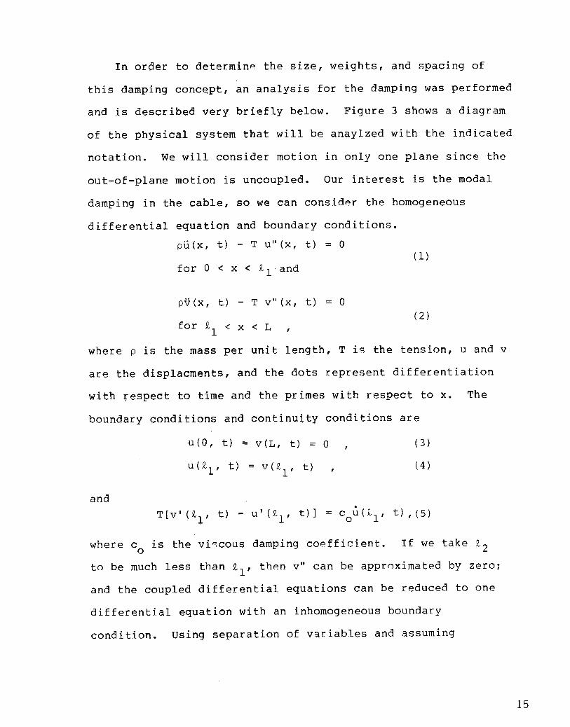
In order to determin~ the size, weights, and spacing of
this damping concqpt, an analysis for the damping was performed
and is described very briefly below. Figure 3 shows a diagram
of the physical system that will be anaylzed with the indicated
notation. We will consider motion in only one plane since the
out-of-plane motion is uncoupled. Our interest is the modal
damping in the cable, so we can consider the homogeneous
differential equation and boundary conditions=
pu(x, t) -Tu’’(x, t) =0(1)
pv(x, t) -Tv’’(x, t) =~(2)
for 11 <x<L,
w’here p is the mass per unit length? T is the tension~ u and v
are the displacements, and the dots represent differentiation
with respect to time and the primes with respect to x. The
boundary conditions and continuity conditions are
U(o, t) = v(L, t) = O , (3)
(4)
and
T[v’(kl, t) - U’(L1, t)] = CO:(L1, t),(s)
where c is the vi%cous damping co~fficient. If we take !L2o
to be much less than 11, then V“ can be aPPr~ximated bY zero;
and the coupled differential equations can be reduced to one
differential equation with an inhomogeneous boundary
condition. Using separation of variables and assuming
15
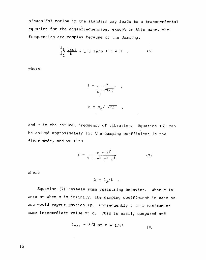
sinusoidal motion in the standard way leads to a transcendental
equation for the eigenfrequencies, except in this case, the
frequencies are complex because of the damping.
‘1 tan~.— + i c tanc + 1 = O , (6)% b
where
and u is the natural frequency of vibration. Equation (6) can
be solved approximately for the damping coefficient in the
first mode, and we find
(7)
where
Equation
zero or when
A = 12/L .
(7) reveals some reassuring behavior. When c is
c is infinity, the damping coefficient is zero as
one would expect physically. Consequently ~ is a maximum at
some intermediate value of c. This is easily computed and
L = A/2 at c = l/-ITAmax (8)
16

Figure 4 shows a series of plots of the damping
coefficient i as a function of c for various values of A. One
can see the maxima of L shift as A is increased. Also note
that the curves become steeper near the maximum L with
increasing A.
,10I
0,c 5 10 15 20
C7T
FIGURE !+ - THE VARIATION IN DAMPING FACTOR WITH
VISCOUS DAMPING COEFFICIENT
17

The magnitud~ of the damping coefficient that can be
obtained with this systeq appears quite attractive. With the
damping syst~m connected to the cable one-tenth of ~he distance
along the cable (A = 0.1), damping values as high as five
percent of critical can be obtained. Even if only two percent
damping were achieved, this still represents an increase by a
factor of ten over the damping inherently in the cables.
The analysis of the cable damping was performed assuming
viscous damping, but the actual damping mechanism is Coulomb
friction. By equating the energy dissipated in one cycle of
the viscous damper to that of the friction damper, a
relationship between the viscous coefficient and friction
coefficient can be obtained. The energy dissipated in one
cycle is
f
21r/(J.!
‘D = ‘D “~dto
where FD
is the damping force. Evaluating UD for both the
viscous damping and the friction damping and equating the
results, we find that the sliding weight W which must be
suspended by the cable for the same energy dissipation is
c~ ~ u U(xo)w=
4 p Cos y (9)
where P is the friction coefficient, Y is the elevation angle
of *he friction surface, and U(xo) is the displacement of the
18

cable at the attachment point. Equation (9) reveals the basic
nonlinearity of friction damping as opposed to viscous damping;
the weight required for equivalent damping is proportional to
the displacement U(XO). Thus , the equivalent co goes down
with increasing amplitude and goes up with decreasing
amplitude. Consequently, an anticipated displacement U(xo)
must be known before an equivalent weight W can be calculated.
This nonlinearity also reveals itself when the cable motion is
s:mall,then the equivalent c is large, and the dampero
creates a large force relative to the elastic force at the
connection. This force just drives a node point and the energy
dissipation goes to zero.
This damping scheme was tested on the 17-Meter Research
Turbine at Sandia National Laboratories in order to determine
the effect of the damping on the cable vibrations. A single
pair of friction dampers at right angles were connected to just
one of the four guy cables four meters from the cable end (A =
0.1). A pair of 18 kg weights were used as the sliding
elements. The surfaces were inclined at thirty-five degree
from the horizontal and had a friation coefficient u = 0.20.
The size, mass, and location of these dampers were quite
reasonable and should have yielded between two to five percent
damping depending on the amplitude of the cable motion.
Acceleration measurements were takqn on the cable in the
horizontal and vertical directions while the turbine was
operating in a variety of wind speeds. The acceleration data
19

was analyzed using the Method of Bins [Ref. 7] so that the rms
acceleration amplitude could be plotted as a function of wind
speed. One would expect the cable vibrations to increase with
wind speed since the excitation increases. Measurements were
taken with and without the damping system connected and at
thr~e different cable tensions, T1, T2, and T3.
The highest tension, T1 = 80 kN, caused the first cable
frequency to be about twenty percent higher than two per rev;
the second tension, T2 = 54 kN, produced a cable frequency
very near two per rev; and the third tension, T3 = 27 kN,
created a cable frequency at about seventy percent of two per
rev. The Bins data for the horizontal and vertical
accelerations with the three tensions are shown in Figures
5-14. The first five figures are the horizontal acceleration
plots: Tension 1 without damping, Tension 2 without damping,
Tension 2 with damping, Tension 3 without damping, and Tension
3 with damping. The last five figures are the vertical
acceleration plots in that same order. Note the tremendous
difference in the acceleration levels between Figs. 5 and 6,
and then adding the damper in Fig. 7 brings the acceleration
levels back down to the levels of Fig. 5. Figs. 8 and 9 are
the undamped and damped cases for tension T3. There is
hardly any difference between the plots. This is the expected
result since this case is not a resonant response, but merely a
forced response, and damping does very little unless a
resonance exists. Figs 10-14 show the same data but for the
vertical direction. The same trends are exhibited in these
figures.
20

AC
CE
LE
RA
TIO
N(G
’s)
r+
00
00
.t-
0‘~
”
-+0
N
‘m.
.’
m . . . . . ,. . ‘.
*
: :■
■
AC
CE
LE
RA
TIO
N(G
’s)
-n zA
CC
EL
ER
AT
ION
(G’s
)
5 WI
00
00
PI’
-
L.n
-0L
min
L-u
00
L0
;w
l.-
&i+
-L1
,,
1
. . : . . : . . . . , *.
.m m . .
. . . . . : .’

0
FIGIJRE8 -
o
FIGURE 9 -
mm
.,
..1,.e?.
●
,*’”,mm
■ a,m.mmm.n~
?’, , !
16 32 48 64
WIND SPEED (KM/HR)
CABLE HORIZONTALACCELERATION
VERSUS WIND SPEED FOR TENSION 3, UNDAMPED
. .*.. .
●a.“
.s
, =,....=”*’”.,. .*-= D””
1 , , t
16 32 48 64
WIND SPEED (KM/HR)
CABLE HORIZONTAL ACCELERATION
VERSUS WIND SPEEP FOR TENSION 3, DAqPED
22

■ “..W,
. . ..s8 mm-.a~m~mmm,,=,.mmmvm
o,o- , r r
0 16 32 48 64
NIND SPEED (KM/HR)
FIGURE 10 - CABLE VERTICAL ACCELERATIONVERSUS
WIND SPEED FOR TENSION 1, UNDAMPED
.’8
m,,mm, m
m ,m. m.“,m
s“” ■ ■
a■ .m
●
o 16 32 48 64
WINO SPEED (KM/HR)
FIGURE 11 - CABLE VERTICAL ACCELERATIONVERSUS
WIND SPEED FOR TENSION 2, UNDAMPED
‘m
o 16 32 48 64WIND SPEED (KM/HR)
FIGURE 12 - CABLE VERTICAL ACCELERATIONVERSUS
WIND SPEED FOR TENSION 2, DAMPED
* m,,
*.
.,.“
,s~warn.m.,.?87
m... m=mn’9-
0
FIGIJRE13 -
16 32 48 64
141NDSPEED (KM/tiR)
CABLE VERTICAL ACCELERATIONVERSUS
WIND SPEED FOR TENSION 3, UNDAMPED
m
a,8
*.m=
.
.“.....,.8s-””=
=mm. mm.m..
o 16 32 48 64
WIND SPEED (KM/HR)
FIGURE 14 - CABLE VERTIC4L ACCELERATIONVERSUS
WIND SPEED FOR TENSION 3,DAMPED
24

Inclusions
The design of the guy cables is not a straightforward
process. It must be iterative since there are multiple
requirements and constraints, and it must be interactive with
the rest of the structural design since the cable stiffness
affects the modal frequencies.
The cable damping concept demonstrated here appears to work
quite well in reduci’ng resonant vibrations of the cables. The
system appears simple to design and install. Consequently,
this system or something similar can be used to eliminate the
constraint of cable vibrations on the design of the guys.
Acknowledqement5—
G. M. McNerney collected and processed all.of the
acceleration data for the Bins plots, and his contributions
were essential to this bork. R. O. Nellums’ discussions with
me were most helpful and are acknowledged.
References.
1.
2.
3.
Reuter, R. C., Jr., Tie-Down Cable Selection and InitialTensioning for the Sandia 17-Meter Vertical Axis WindTurbine, SAND 76-0616 (Albuquerque, NM: Sandia NationalLaboratories, 1977).
Reuter, R. C., Jr., Vertical Axis Wind Turbine Tie-DownDesign with an Example, SAND77-1919 (Albuquerque, NM:Sandia National Laboratories, 1977).
Carrie, T. G., “Guy Cable and Foundation Design Techniques,”SAND80-0984, Proceedings of the Vertical Axis Wind Turbine(VAWT) Design Technology Seminar for Industry, (Albuquerque,NM: Sandia National Laboratories, 1980).
25

4. Auld , H. E. and Lodde, P. F., A Study of Foundation/AnchorRequirements for Prototype Vertical-Axis Wind Turbines,SAND78-7046 (Albuquerque, NM: Sandia NationalLaboratories, 1979).
5. Lodde, P. F., Wind Turbine Foundation Parameter Study,SAND80-7015 (Albuquerque, NM: Sandia NationalLaboratories, 1980).
6. Nellums, R. O., “Economic Assessment of the Darrieus WindTurbine,” AIAA Paper 80-0614, Proceedings of the AIAA/SERIWind Energy Conference, April 9-11, 1980, Boulder, Colorado.
7. Sullivan, W. N., “5-Me~er Turbine Field Testing,”SAND76-5586, Proceedings of the Vertical Axis Wind TurbineTechnology Workshop, May? 1976 (Albuquerque, NM: SandiaNational Laboratories, 1976),
26

TID-45CCI--R66UC-6C (2E3)
Ae~~ ~~gi*eering~epartrnent(2)Wichita State Universityhichita,KS 6720~Pttn: P. Snyeer
w. &entz
K. E. Akins, Assistant PrQfessorC(epartmentof L?ngineeringScienceand !!echanics
Virginia Polytechnic Institute &State University
Flacksburg, VP 2406C
fi.lcoaLaboratories (5)Alcoa Technical CenterAluminum Company of AmericaAlcoa Center, FA 15f169
Pttn: D. Y. Ai?..C. CraigJ. ‘I.HuangJ. P. Jon?bockP. }’.Vosbur’gh
Mr. Fobert E. ?.llenGeneral ?tanager12ynergyCorporationP.C. Fox 4281269 Union AvenueLaconia, NE 03246
American hind Energy Association1609 Connecticut Avenue NWWashington, CC 20009
E. E. AndersonSouth Dakota School of Ninesand Technology
Department of Mechanical Eng.Rapid City, SE 57701
Scott P.nderson318 F!illisHalluniversity of VermontBurlington, VT 0540!5
cl.‘I.P.nkrumtOF\Cffice of CommercializationZ,O~;assachusettsAvenue NhY.ailStation 2221CWashington, LC 205E5
Eolt AshleyStanford UniversityDepartment of Aeronautics andAstronautics Mechanical Eng.
Stanford, CA 94305
Kevin AustinConsolidated Edison Company ofNew York, Inc.
4 Irving PlaceNew York, NY 10003
E. H. Earksdale, Jr.Iiayes,Seay, Nattern, and Kattern131!5Franklin Road SWPoanoke, VA 24016
Dr. E. J. EaumInstitute of Geophysicsand Planetary PhysicsUniversity of CaliforniaRiverside, CA ?2521
Gaston Beaulieu, M.SC.Instit de recherched’Hydro-Qu&bec1800 Mont&e Ste-JulieVarennesr Que.Canada JOL2P0
F. K. BechtelWashington State UniversityDepartment of Electrical Eng.College of EngineeringPullman, hA 99163
k!.E. ~eecherArizona State UniversitySolar Energy CollectionUniversity LibraryTempe, AZ 85281
Leon l?jervigCivilingenior, MCIF“Osterbyhus”, 6990 UlfborgCK6990DENMARK
K. BergeyUniversity of OklahomaAero Engineering DepartmentNorman, CK 73C69
27

Steve ~lakeWind Fnergy SystemsRoute 1, Box 93-AOskaloosar KS 66066
Robert E?rulleFcConnell-Louglas P.ircraftCorp.p.~. POX 516Department 341, Building 32/2St. Louis, NC 63166
F. CamereroFaculty of Ppplied ScienceUniversity of SherbrookeSherbrooke, QuebecCANACA JIK 2R1
cERcEi’+1
49 Rue du Commandant I?olland93350 Le BourgetFFANCl?Attn: G. Earrieus
J. Eelassus
Professor V. A. L. ChasteauSchool of EngineeringUniversity of AucklandPrivste PacjAuckland, NEW ZFALAND
FJowardT. ClarkMcDonnell Aircraft CorporationF’.@.~OX 516Department 337, Puilding 32St. Louis, MO 63166
Dr. R. N. ClarkUSDA Agricultural Resea$ch Svc.Southwest Great Plains
Research CenterBushland, TX 79012
Joan D. CohenConsumer Outreach CoordinatorState of New YorkExecutive DepartmentState Consumer Protection Foar$99 \$ashingtonAvenueAlbany, NY 12210
Er. L. E. CromackPssociate Frofessor~~echanicalznd Aerospzce Eng.
EepartinentUniversity of MassachusettsAmherst, NA 01003
Gale E. CurtisTumac Industries656 Ford StreetColorado Springs, CO 80915
120E/ALO (2)Albuquerque, KY 87115Attn: G. P. Tennyson
COL Eeadqvarters/hESr (20)600 E Street B?iiWashington, DC 20545Attn: D. F. Ancona
C. E. AsplidenL. V. Pivoneii.C. Reddick
C. W. EoddSchool of EngineeringSouthern Illinois UniversityCarbondale, IL 62901
D. D. Doerr&aiser Alumi,nu and
Chemical Sales, Inc.6177 Sunol Blvd.P. O. BOX 877Pleasonton, CA 94566
Dominion AluminumFabricating Ltd. (2)
3570 Hawkenstone RoadMissi.ssauga,OntarioCANADA L5C ,2u8Attn: L. Schienbej_n
C. Vlood
J. B. DragtNederlands Energy Research
Foundation (E.C.N.)Physics DepartmentWesterduinweg 3 Patten (nh)THE NETHERLANDS
c. E. Ll~erkinBattelle-Facific Northwest Lab,F.O. FOX 999Richland, tip 99352
Frank F’.Eldridge, Jr.The Mitre Corporation1820 Eolley Kadison Plvd.McLean, LA. 22102
28
Electric Power Research Institute3412 Hillview AvenueFalo Altor CA 94304Attn: E. Eemeo
F,ichardG. Ferreira, ChiefThe Resources AgencyDepartment of Kater Reso~rcesEnergy Eivision1416 Sth StreetP.c. BOX 368Sacramento, CA. 95P02
Finley;~wR;ngland Geosystemsl>,OQ~OX 128East Gerry, KH 03041
:JamesD. Fock, Jr.I)epartmentof Aerospace
Engineering Sciences[Universityof ColoradoBoulder, CO 80309
[)r.Lawrence C. FrederickPublic Service Company
of New Hampshire1.000Elm StreetManchester, NH 03105
H. GerardinMechanical Engineering Dept.Faculty of Sciences & Eng.[JniversiteLaval-QuebecCANADA GIK 7P4
L. GilmoreAmarillo CollegeAmarillo, TX 79100
Paul GipeKind Fewer CiqestP.c. 130x539Harrisburg, PA 17108
Roger T. Griffiths“UniversityCollege of SwanseaDept. of Mechanical Eng.Singleton Park,SwanseaSA2 8PP‘UNITEDKINGDOM
Richard Had&ad101 ArizonaP.O. Box 530El Paso, TX 79944
A. A. HagmanKaiser Aluminum and
Chemical Sales, Inc.14200 Cottage Grove Ave.Dolton, IL 60419
Nartin L. Hally, Section YanagerProject DepartmentElectricity Supply18 St. Stephen’s GreenCublin 2, IRELAND
Professor N. P. HamMassachusetts Institute of Tech.77 Massachusetts AvenueCambridge, MA 02139
C. F. HarrisWind Engineering CorporationA’irportIndustrial AreaBOX 5936Lubbock, TX 79415
W. L. HarrisAero/Astro 12epartmentMassachusetts Institute of Tech.Cambridge, MA 02139
Terry Healy (2)Rockwell InternationalRocky Flats PlantP.O. BOX 464Golden, CO 80401
HelionF.O. BOX 4301Sylmar, CA 91342
Eon HinrichsenAssociate EditorAME?IOKVAFack, S-10405StockholmSWEDEN
Sven HugossonBOX 21048S. 100 31 Stockholm 21SWEDEN
o. IgraDept. of Mechanical Eng.Ben-Gurion University
of NegevBeer-Sheva, ISRAEL
29

Indian Cil Corporation, ~td.Narketing Eivision254-C, Er. Annie Eesant RoadFrabhadevi, !20mbay-400025IN!21A
JFF Scientific Corporation2 Jewel DriveWilmington, YD ~lp17Attn: E. E. Johansori
Lr. Cary L. Johnson, F.E.Electrical Engineering 12epartmentFansas State UniversityP+anhattan,KS 66506
E. C. Kaddyr Jr.‘POX35331 Union StreetHillsboro, ~H 63244
Kaman Aerospace CorporationCld Windsor RoadEloomfieldr CT 06C02Attn: k;.Fstesol
P L.\. Katzenberg2820 Upton St. NWKsshington, EC 200CP
Robert E. F;ellandThe College of Trades and Tech,~.~. BOX 1693Frince Fhilip Crive~t. John’s, NewfoundlandCANADA.F.lC5F7
5. KingNatural Fewer, Inc.l~ewEoston, I;H 0307C
Larry KinnettF.C,.POX 6593Santa Earbara, CA 93111
Samuel R. Kohler272 Cld Lelp F.oadLancaster, PA 176(!2
G. F.rauss!;ic!:igan.State ~niversityEivision of Engineering researchEast Lsnsinq, NI 48P24
Carol Lamb25F4 East Geddes AvenueLittleton, C5 80122
Lawrence Llvermcre ~ai>oraroryP,c. Box .!308L-34GLivermore, CA 9455~
Attn: c. w. Born
M. LechnerPublic Service of
New MexicoP. O. BOX 2267Albuquerque, NM 87103
Kalman Nagy LehoczkyCort Adelers CT. 300s10 2KPRKAY
Ceorge E. LennoxIndustry EirectorKill Froducts LivisionReynclds Eetals Company6601 iiestEroad StreetRichmond, VA 23261
J. LernerState Energy CommissionResearch and 12evelopmentZivision1111 Eowe ?.venueSacramento, CA g~p~~
L. LiljidahlEuilding 3C3Agriculture Fesearch CenterUSLA!3eltsvillq,Y4E 2(!705
P. 5. s. LissamanAeroenvironment, Inc.660 South Arroyo FarkwayFasadena, CA 91105
One LjqngstromFFA, The Aeronautical Research
InstituteBox 11021s-16111 BrommaSWEDEN
, ;“‘L. >. Logan. . Turbine Corporation
Glde Courthouse EuildingCanfield, GE 444G6
J. P. LonqendyckSiltex7 Capitol Drivek!oonachie,IiJ C7C74
30

Los Alamos Scientific
Laboratoriesp-c. BOX 1663I.OSAlamos, KM P7544?~ttn: J. D. Ealcomb C-DC-T
Beatrice de Saint LouventEstablissement d’Etudes et
de Recherches Meteorologigues77, Rue de Serves92106 130ulogne-Rillancourt CedexFRANCE
Lrnel L. LutherSenior AssociatePRC Energy Analysis Co.7600 Cld Springhouse Rd.McLean, VA 22101
“L.Ii.J. Maile48 York Mills lid.Willowdale, OntarioCANAEA M2P 1E4
David J. MalcolmStructural DynamicistDAF Indal Ltd.3570 Hawkestone Rd.Mississauga, Ont.,Canada L5C2V8
.E. L. MarkowskiMotolola, Inc.G.E#12.Mail Drop 14298201 E. McDowell Rd.P.o. BOX 1417Scottsdale, AZ t5252
Jacques R. MaroniFord Motor CompanyEnvironmental Research and
Energy Planning DirectorEnvironmental and Safety
Engineering StaffThe American RoadDearborn, MI 48121
Frank Matanzo‘ 12ardalenAssociates15110 Frederick RoadWoodbine, MD 21797
H. S. Matsuda, KanagerComposite Materials LaboratoryPioneering R&!2LaboratoriesToray Industries, Inc.Sonoyama, Ctsu, ShigaJAPAK 520
J. F. licCOnnellTumac Industries, Inc.650 Ford St.Colorado Springs, CO E0915
James MeiggsKaman Sciences CorporationP.O. ~OX 7463Colorado Springs, CC /30933
R. N. MeroneyColorado State UniversityDepartment of Civil EngineeringFort Collins, CC 80521
G. If.MonssonDepartment of Economic Planningand 12evelopment
Barrett EuildingCheyenne, MY 82002
~TsA Lewis ~esesrch center (4)
21000 Brookpark RoadCleveland, OH 44135Attn: J. Savino
K. L. ThomasW. RobbinsK. Kaza
Anthony A. NeddThe Power Company, Inc.P.o. Box 221Genesee Depot,WI 53217
V. NelsonWest Texas State UniversityDepartment of PhysicsF.O. ~OX 248Canyon, TX 79016
Leander NicholsNatural Power, Inc.New Boston, NH 03070
Ronald NousainJ?.o.I?ox111Rome 1132Los Angeles, CA 90051
31

Oklahoma State University (2)Stillwater, GK 76C74Attn: Ii.L. Hughes
FE DepartmentL. K. KcLaughlinME Department
Oregon State University (2)Corvallis, OR 9733.1P.ttn: R. E. Wilson
ME DepartmentR. h. ThresherME Department
Fat F. C’F.ourkePrecinct 4County CommissionerCity-County EuildingEl Paso, TX 79961
v. h. FaalmanDow Chemical IJSP.Research Center2806 Mitchell Drivehzlnut Creekr C> 945’38
Ion FaraschivoiuII?EQ1800 montee Ste-JulieVarennes, QeubecCANFIEAJCL 2Po
R. A. ParmaleeNorthwestern UniversityDepartment of Civil EngineeringE’vanston,IL 60201
Helge FetersenRiso Nationa,lLaboratoryDK-4000 RoskildeDENMARK
Wilson Prichett, IIINational Rural Electric Coop.?.ssociation
1800 Massachusetts Avenue NWWashington, DC 20C36
S. Quraeshi, Eng.Shawinigan En9. comPanY ‘td”620 Dorchester Blvd. WeWest, MontrealQuebec, Canada, H3B1N8
13r. Barry Rawlings, ChiefDivision of Mechanical Eng.Commonwealth Scientific and
Industrial ResearchOrganization
Graham Road, HighettVictoria, 3190fi.tiSTRALIA
Thomas W. ReddochPssociate ProfessorDepartment of Electrical.!Zng.The University of TennesseeKnoxville, TN 37916
Ray G. RichardsAtlanpic Wind Test SiteF.o. Eox 1s9TicjnishP.E.I.COB 2BC CANAPA
A. RobbMemorial University of
~~ewfoundlandFaculty of Engineering and
Applied SciencesSt. John’s NewfoundlandCANADA AIC 5s7
J. R. RodriguezSolarwind Energy Corporation1163 Fomona RoadUnit ACorona, CA 917~o
L?r. -Ing. Hans RuscheweyhInstitut fur LeichbauTechnische FlochschuleAachenWUllrlerStra~Se ~
GERMANY
Gwen SchreinerLibrarianNational Atomic KupeurnAlbuquerque, liM 87185
Eouglas E. Seely, F.E.Us. Department of EnergyP.O. BOX 3621102 NE HolladayPortland, CR 97208
32

Arnan SeginerProfessor of AerodynamicsTechnion-Israel Institute of
TechnologyDepartment of Aeronautical
EngineeringHaifa, ISRAEL
12r. Horst Seizer12ipl.-Fhys.W’ehrtechnikund EnergieforschungERNO-Raumfahrttechnik GmbHHunefeldstr. 1-5Postfach 10 59 092800 Bremen 1GERMANY
E. Se.vierRocket and Space LivisionEristol Aerospace Ltd.P.c. Eox !374Winnipeg, ManitobaCANADA R3C 2S4
P. N. ShankarAerodynamics DivisionNational Aeronautical Laboratory2angalore 560017INDIA
David SharpeKingston PolytechnicCanbury park RoadKingston, SUrrf2Y
LltVITED KINGDOM
E. G. ShepherdCclrnellUniversitySibley School of Necha.nicalandAerospace Engineering
Ithaca, NY 14853
E:r . Fred SmithMechanical Engineering
13epartmentHeadColorado State UniversityFt. Collins, CC 60521
Kent SmithInstituto !Iechnologico
Costa RicaApartado 159 CartagoCOSTA RICA
Leo H. SoderholmIowa State UniversityAgricultural Engineering,
FOOm 213Ames, IA ~colo
Bent SorensonRoskilde University CenteryEnergy JGroup, Bldg. 17.2IMFL?FAP.C. BOX 260!JK-400RoskildeDENMARK
Southwest Research Institute (2)P.O. Drawer 28501San Antonio, TX 78284At’tn: W. L. Donaldson,
Senior Vice PresidentR. K. Swanson “
Rick StevensonPoute 2Box 65,Springfield, NC, 65P02
Lale T. Stjernholm, P.E.Mechanical Eesign EngineerMorey/Stjernholm and Associates1050 l:agnoliaStreetColorado Springs, CO 80907
G. k;.Stricker383 Van Gordon 30-559Lakewood, CO 8022E
C. J. SwetRoute 4BOX 358Et. Airy, MD 21771
John TaylorlJationalResearch CouncilASEP2101 Constitution AvenueWashington, EC 20418
k. J. Templin (3)Low Speed Aerodynamics SectiorNRC-National Aeronautical
EstablishmentOttawa 7, OntarioCANADA KIA 0R6
33

Texas Tech University (3)P.c. Fox 43E?9Lubbock, TX 79409
Attn: K. c. Vehta, CF DepartmentJ. Strickland, ME departmentJ. Lawrence, ME Department
Fred ThompsonP.tari,Inc.155 ~~offettpark DriveSunnyvale, CA 94086
J. M. Turner, Group LeaderTerrestrial Energy Technology
Program OfficeEnergy Conversion EranchAerospace Fewer DivisionAero Propulsion Laboratory~epal-tment of the Air ForceAir Force Wright Aeronautical
Laboratories (AFSC)wright-Eatterson Air Force Ease, CH
45433
Otto de VriesNational Aerospace LaboratoryAnthony Fokkerweg 2Amsterdam 1017THE NETHERLANDS
R. haltersWest Virginia UniversityDepartment of Aero Engineering1062 Kountz PvenueMorgantown, KV 26505
E, J. harcholBonneville Power AdministrationF.0. BOX 3621Portland, CR 97225
E. F. Warne, ManagerEnergy and Power SystemsERA Ltd.Cleeve Fd.LeatherheadSurrey KT’227SAENGLANC
[.nitedEnqineers and Constructors, Inc.A6vanced engineering !3epartment30 South 17th StreetPhiladelphia, PA 19101Attn: A. J. Itaralis
University of New Mexico (2)New Xexico Engineering Research
Institutecampus, F.C. ~OX 25Albuquerque, N.M. 87131Attn: G. G. Leigh
University of New Mexico (2)Albuquerque, NM 87106Attn: K. T. Feldman
Energy Research Centerv. SloglundME Department
Nishikant R. Vaidya, Ph.D.Senior Project EngineerD’AppoloniaConsulting Engineersr Inc.10 Duff Roadr Pittsburghr VA 15235
Jan VacekEolienne experimentaleC.F. 27gr Cap-aux-MeulesIles de la ~Kadeleine,~uebecCANALA
Irwin E. VasSolar Energy Research Institute1617 Cole Slvd.Golden, CC P0401
PC. R. hatson, project kanagerThe Energy CenterPennine house4 Osborne TerraceNewcastle upon Tyne NE2 lNEUNITED KINGECK
R. J. hatsonWatson Eowman Associates, Inc.1280 Niagara St.Buffalo, NY 14213
R. G. hattsTulane L’niversityDepartment of Mechanical EngineeringNew Orleans, LA 70018
W. G. Wells, F.F.Associate ProfessorMechanical Engineering DepartmentMississippi State UniversityMississippi State, PiS 39762
T. Kentink, Jr.University of AlaskaGeophysical InstituteFairbanks, AK 99701
;iestTexas state UniversityGovernment Depository LibraryNumber 613Canyon, ‘IX 79015
34
Wind Energy ReportQ(2X14102 S. Village Ave.Rockville Centre, NY 11571Attn; Farrell Smith Seiler
Wind ProgramManagerWisconsinDivisionof State Energy8th Floor101 South Webster StreetMadisc)n,WI 53702
Richard E. hongAssistant rirectorCentral Golar Energy ReSearCh Corp.1200 Sixth Street328 Executive FlazaLetroit,MI 46226
1000 G. A. Fowl.er1200 L. E. Smith3141 T. L. herner (5)3151 W. L. Garner (3)
For DOE/TIC (Unlimited Release)3161 J. E. Mitchell (15)3161 P. S. Wilson4533 J, W. Reed4700 J. H. Scott4710 G. E. E!randvold4715 R. E. Eraasch4715 J. D. Cyrus4715 R, L. Grover47$5 E. G. Kadlec4715 F. C. Klimas4715 M. T. Kattison4745 R. C. Nellums4715 W, N. Sullivan4715 R, A. Katson4715 r. F. wolf4715 ,M. E. horstell5000 0. E. Jones!5510 D. B. Hdyl;S ,55210 T. E. Lane5523 R. C. Reuter, Jr.5523 T.mG. Carrie (20)5523 D. B. Clauss5523 D. W. Lubitz5523 D. A. P~pelka5523 P. S. Veers5523 File5530 W. Herrrnann5600 D. B. Schuster5620 M. M. Newsom5630 R. C. Maydew5633 R. E. Sheldahl5636 J. K.,COle5636 D. E. Eerg5636 W. H. Curry8266 E, A. AasDOE/TIC (25)
(R. P. Campbell, 3172-3)
35f