gx-2009 user setup program operator’s manual · gx-2009 user setup program operator’s manual...
TRANSCRIPT

GX-2009 User Setup ProgramOperator’s Manual
Part Number: 71-0162RK
Revision: H
Released: 6/20/17
www.rkiinstruments.com
Warranty
RKI Instruments, Inc. warrants gas alarm equipment sold by us to be free from defects in materials and workmanship, and performance for a period of one year from date of shipment from RKI Instruments, Inc. Any parts found defective within that period will be repaired or replaced, at our option, free of charge. This warranty does not apply to those items which by their nature are subject to deterioration or consumption in normal service, and which must be cleaned, repaired, or replaced on a routine basis. Examples of such items are:
Warranty is voided by abuse including mechanical damage, alteration, rough handling, or repairs procedures not in accordance with the instruction manual. This warranty indicates the full extent of our liability, and we are not responsible for removal or replacement costs, local repair costs, transportation costs, or contingent expenses incurred without our prior approval.This warranty is expressly in lieu of any and all other warranties and representations, expressed or implied, and all other obligations or liabilities on the part of RKI Instruments, Inc. including but not limited to the warranty of merchantability or fitness for a particular purpose. In no event shall RKI Instruments, Inc. be liable for indirect, incidental, or consequential loss or damage of any kind connected with the use of its products or failure of its products to function or operate properly.This warranty covers instruments and parts sold to users only by authorized distributors, dealers, and representatives as appointed by RKI Instruments, Inc.We do not assume indemnification for any accident or damage caused by the operation of this gas monitor and our warranty is limited to replacement of parts or our complete goods.
Absorbent cartridges Batteries
Pump diaphragms and valves Filter elements
Fuses
2 • Warranty

Table of ContentsWarranty . . . . . . . . . . . . . . . . . . . . . . . . . . . . . . . . . . . . . . . . . . . . . . . . . . 2Table of Contents . . . . . . . . . . . . . . . . . . . . . . . . . . . . . . . . . . . . . . . . . . . 3Introduction . . . . . . . . . . . . . . . . . . . . . . . . . . . . . . . . . . . . . . . . . . . . . . . 4System Requirements . . . . . . . . . . . . . . . . . . . . . . . . . . . . . . . . . . . . . . . 6Installing the GX-2009 User Setup Program . . . . . . . . . . . . . . . . . . . . . 6Installing a Newer Version of the GX-2009 User Setup Program . . . . . 7IrDA Downloading Cable . . . . . . . . . . . . . . . . . . . . . . . . . . . . . . . . . . . . 10
Installing an IrDA Adapter Cable . . . . . . . . . . . . . . . . . . . . . . . . . . . 10
Windows® Wireless Link Operation Note . . . . . . . . . . . . . . . . . . . . .11Launching the Program . . . . . . . . . . . . . . . . . . . . . . . . . . . . . . . . . . . . . 13Connecting a GX-2009 to the User Setup Program . . . . . . . . . . . . . . 15Read Commands . . . . . . . . . . . . . . . . . . . . . . . . . . . . . . . . . . . . . . . . . . 19
Instrument Information . . . . . . . . . . . . . . . . . . . . . . . . . . . . . . . . . . 20Information Get & Save . . . . . . . . . . . . . . . . . . . . . . . . . . . . . . . . . 23
Write Commands . . . . . . . . . . . . . . . . . . . . . . . . . . . . . . . . . . . . . . . . . . 25Update . . . . . . . . . . . . . . . . . . . . . . . . . . . . . . . . . . . . . . . . . . . . . . . 25Date/Time Set . . . . . . . . . . . . . . . . . . . . . . . . . . . . . . . . . . . . . . . . . 26Calibration . . . . . . . . . . . . . . . . . . . . . . . . . . . . . . . . . . . . . . . . . . . . 27
Setting Commands . . . . . . . . . . . . . . . . . . . . . . . . . . . . . . . . . . . . . . . . 34Power Off. . . . . . . . . . . . . . . . . . . . . . . . . . . . . . . . . . . . . . . . . . . . . 34Load Local File . . . . . . . . . . . . . . . . . . . . . . . . . . . . . . . . . . . . . . . . 35Store Local File . . . . . . . . . . . . . . . . . . . . . . . . . . . . . . . . . . . . . . . . 38Detail Settings . . . . . . . . . . . . . . . . . . . . . . . . . . . . . . . . . . . . . . . . . 41Updating an Instrument’s Detail Settings. . . . . . . . . . . . . . . . . . . . . 47Exit. . . . . . . . . . . . . . . . . . . . . . . . . . . . . . . . . . . . . . . . . . . . . . . . . . 50Compare Master . . . . . . . . . . . . . . . . . . . . . . . . . . . . . . . . . . . . . . . 50
Spare Parts List. . . . . . . . . . . . . . . . . . . . . . . . . . . . . . . . . . . . . . . . . . . . 52
Table of Contents • 3

Introduction
NOTE: The bump test function in Calibration Mode is included in instruments with firmware version 03955 or later installed. See page 45 for a description of the bump test function. GX-2009 instruments shipped after May 2011 include the bump test function. Instruments that have a serial number starting with 04516 or later shipped from the factory with the bump test function available. Instruments that have a serial number starting with 04515 did not include the bump test function when shipped from the factory. The factory setting for the bump test function is off.
CAUTION: Read and understand this manual before using the GX-2009 User Setup Program. Also read and understand the GX-2009 Operator’s Manual included with the GX-2009 portable gas monitor.
Using an advanced detection system consisting of up to four gas sensors, the GX-2009 Personal Gas Monitor detects the presence of combustible gases, oxygen (O2), carbon monoxide (CO), and hydrogen sulfide (H2S) simultaneously. The GX-2009’s compact size and easy-to-use design make it ideally suited for a wide range of applications as described in the GX-2009 Operator’s Manual. Please read the GX-2009 Operator’s Manual first before using the GX-2009 User Setup Program.The GX-2009 User Setup Program allows you to change various instrument parameters not accessible in the GX-2009’s Calibration Mode or User Setup Mode. It also allows you to save parameter configuration files based on instruments’ parameter settings that can be viewed or used to update another instrument’s parameter settings
4 • Introduction
The purpose of this manual is to explain how to use the GX-2009 User Setup Program. You will learn how to:• install and launch the program
• install the downloading cable (if needed)
• connect to the GX-2009 with the program
• change parameters in the GX-2009
• save parameter configuration files that can be opened and viewed in a spread sheet program
• save parameter configuration files that can be uploaded to an instrument to change its parameter settings
• upload parameter configuration files to an instrument to change its parameter settings
Before you get started, be sure to review system requirements in the next section.
CAUTION: The GX-2009 detects oxygen deficiency and elevated levels of oxygen, combustible gases, carbon monoxide, and hydrogen sulfide, all of which can be dangerous or life threatening. When using the GX-2009, you must follow the instructions and warnings in the GX-2009 Operator’s Manual to assure proper and safe operation of the unit and to minimize the risk of personal injury.
CAUTION: The operator of this instrument is advised that if the equipment is used in a manner not specified in this manual, the protection provided by the equipment may be impaired.
Introduction • 5

System RequirementsTo use the GX-2009 Data Logging Software, your personal computer must meet the following requirements:
• Operating Systems: Windows® 7, Windows® 8, or Windows® 10.
• Processor: IBM® compatible PC running Pentium® 2 or higher.
• Memory: 32 MB RAM minimum
• Available Hard Disk Space: 32 MB minimum
• Infrared port or USB port and a USB/IrDA adapter cable
Installing the GX-2009 User Setup Program 1. Launch Windows®.
2. Exit from all applications and open windows.
3. Go to www.rkiinstruments.com/gx2009.
4. Click on the Download tab.
5. Click the User Setup Program Software link.
6. A .zip file will begin to download. Select whether you want to open or save the .zip file.
7. Extract the contents of the .zip file.
8. Double click the setup.exe file.
9. After a few seconds, a screen appears indicating that the InstallShield Wizard is preparing to install the User Setup Program, then the GX-2009 Configuration for User InstallShield Wizard window appears to guide you through installation.
10.Follow the on-screen instructions in the Installation Wizard Window to install the program.
6 • System Requirements
11.If the InstallShield Wizard finds versions of Windows® files on your computer newer than those in the downloaded .zip file, it will ask you if you want to keep these newer files. Click Yes.
12.When the InstallShield Wizard indicates that installation is complete, click the Finish button.
Installing a Newer Version of the GX-2009 User Setup Program
If you are installing a more recent version of the GX-2009 User Setup Program software, you must follow these instructions. 1. Uninstall the currently installed version of the software.
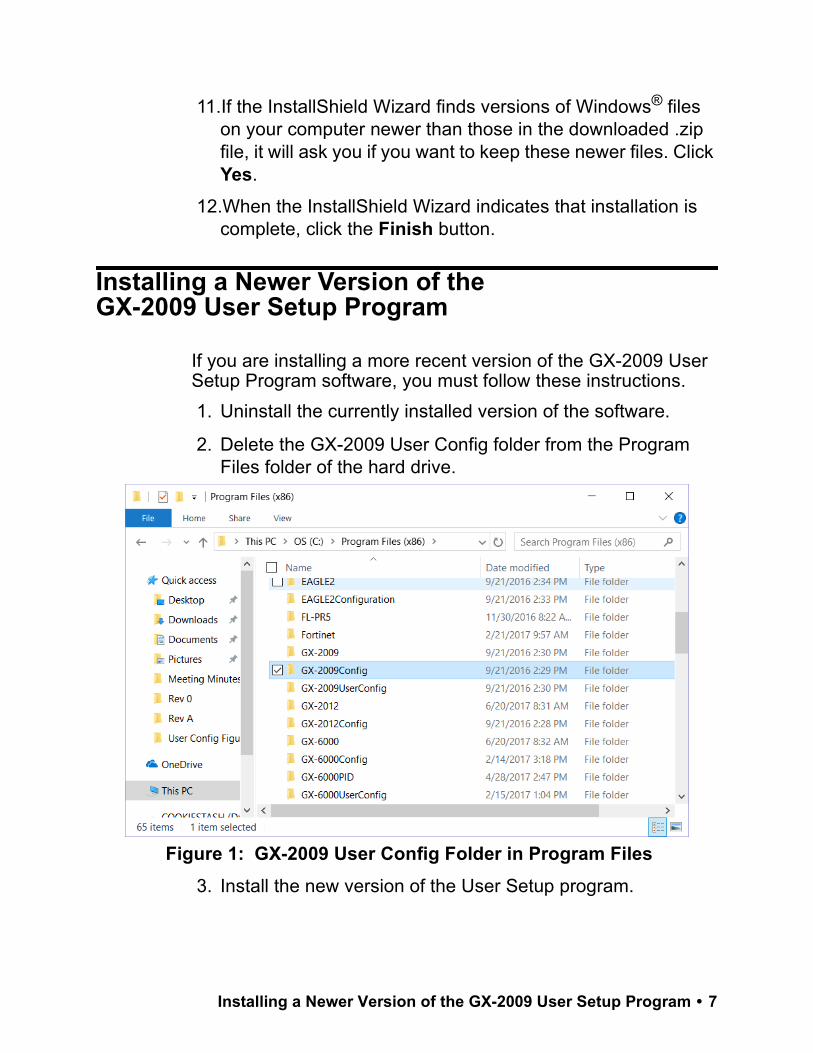
2. Delete the GX-2009 User Config folder from the Program Files folder of the hard drive.
3. Install the new version of the User Setup program.
Figure 1: GX-2009 User Config Folder in Program Files
Installing a Newer Version of the GX-2009 User Setup Program • 7
4. In the Program Files folder on the hard drive, ensure that the GX-2009 User Config folder contains only the following 3 files:
• FILEMOVE.AVI
• RkIrDA11.ocx
• GX2009UserConfig.exe
If any other files are in this folder, delete them.
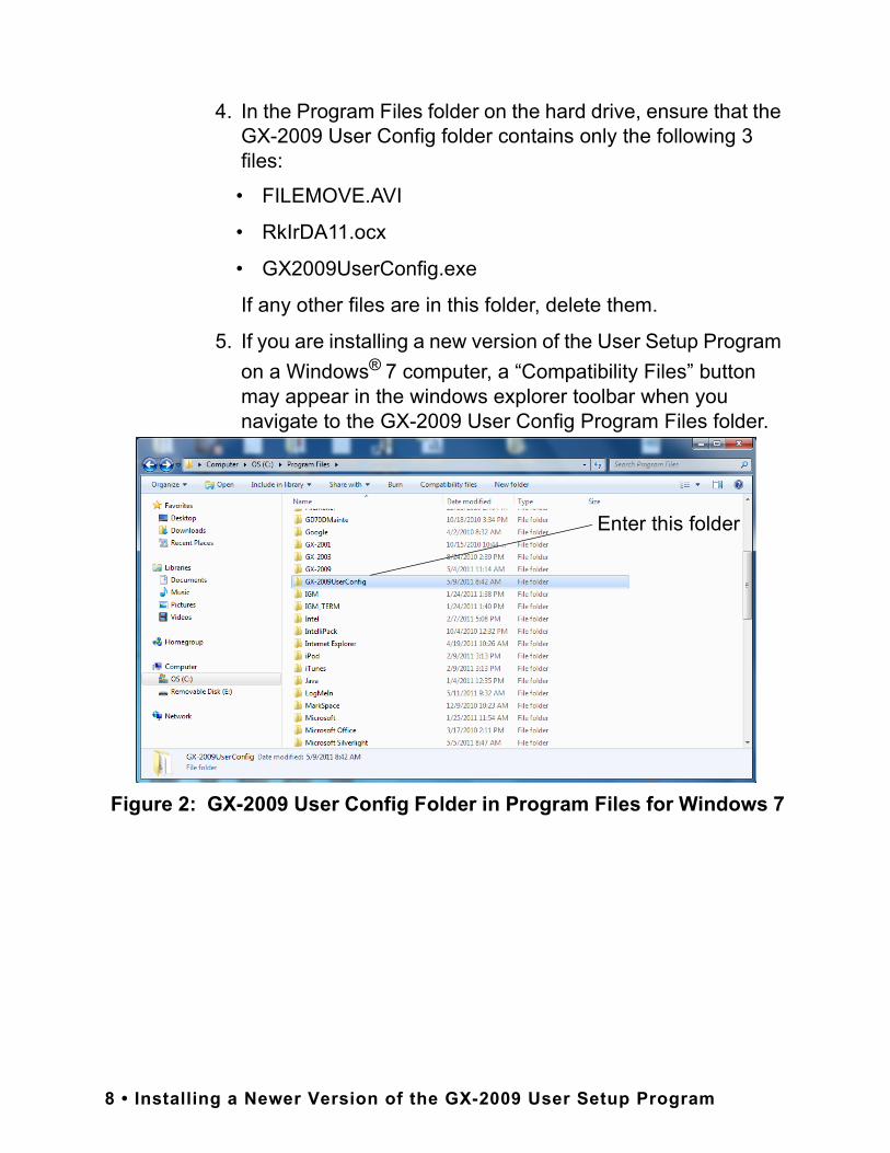
5. If you are installing a new version of the User Setup Program on a Windows® 7 computer, a “Compatibility Files” button may appear in the windows explorer toolbar when you navigate to the GX-2009 User Config Program Files folder.
Figure 2: GX-2009 User Config Folder in Program Files for Windows 7
Enter this folder
8 • Installing a Newer Version of the GX-2009 User Setup Program
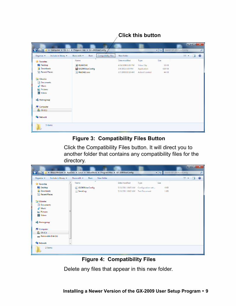
Click the Compatibility Files button. It will direct you to another folder that contains any compatibility files for the directory.
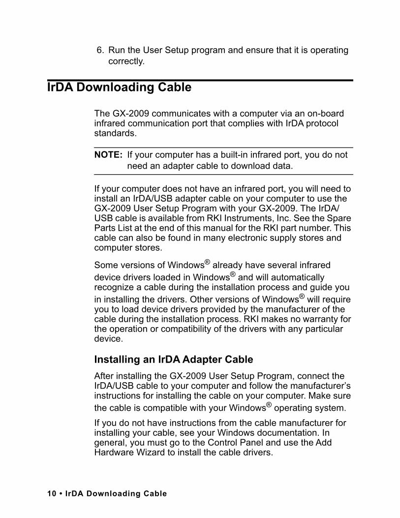
Delete any files that appear in this new folder.
Figure 3: Compatibility Files Button
Click this button
Figure 4: Compatibility Files
Installing a Newer Version of the GX-2009 User Setup Program • 9
6. Run the User Setup program and ensure that it is operating correctly.
IrDA Downloading Cable
The GX-2009 communicates with a computer via an on-board infrared communication port that complies with IrDA protocol standards.
NOTE: If your computer has a built-in infrared port, you do not need an adapter cable to download data.
If your computer does not have an infrared port, you will need to install an IrDA/USB adapter cable on your computer to use the GX-2009 User Setup Program with your GX-2009. The IrDA/USB cable is available from RKI Instruments, Inc. See the Spare Parts List at the end of this manual for the RKI part number. This cable can also be found in many electronic supply stores and computer stores.
Some versions of Windows® already have several infrared device drivers loaded in Windows® and will automatically recognize a cable during the installation process and guide you in installing the drivers. Other versions of Windows® will require you to load device drivers provided by the manufacturer of the cable during the installation process. RKI makes no warranty for the operation or compatibility of the drivers with any particular device.
Installing an IrDA Adapter CableAfter installing the GX-2009 User Setup Program, connect the IrDA/USB cable to your computer and follow the manufacturer’s instructions for installing the cable on your computer. Make sure the cable is compatible with your Windows® operating system.If you do not have instructions from the cable manufacturer for installing your cable, see your Windows documentation. In general, you must go to the Control Panel and use the Add Hardware Wizard to install the cable drivers.
10 • IrDA Downloading Cable

Windows® Wireless Link Operation NoteWhen using an IrDA adapter cable and the GX-2009 User Setup Program on a Windows® computer, it is necessary to make a special setting in the Wireless Link Configuration window for proper communication between the GX-2009 and the GX-2009 User Setup Program. This must be done before attempting to use the program. Follow these steps to make this setting:
1. Click Start on the Windows® Icon Tray.
2. If Control Panel is available to select in the Start menu, select it. The Control Panel will appear.
If Control Panel is not selectable in the Start menu but Settings is, select Settings, then select Control Panel. The Control Panel will appear.
3. Double click on Wireless Link. The Wireless Link Configuration window will appear.
4. Click on the Image Transfer tab.
5. Deselect the selection box for “Use Wireless Link to transfer images from a digital camera to your computer.”
IrDA Downloading Cable • 11
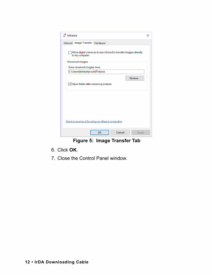
6. Click OK.
7. Close the Control Panel window.
Figure 5: Image Transfer Tab
12 • IrDA Downloading Cable

Launching the Program
1. For Windows® 7 computers, click the Start icon in the Windows® Icon Tray, then select Programs, then select GX-2009 Config. Your operating system may also have a shortcut installed in the Start menu.
For Windows® 8 and Windows® 10 computers, click the Start icon in the Windows® Icon Tray, then click the downward-pointing arrow icon in the lower left corner of the screen, then select GX-2009 Config from the list of apps.
2. The program will launch and the Password Window will appear.
3. The password to enter the User Setup Program is “1994”. Type in the password and click OK to proceed.
Figure 6: Password Window
Launching the Program • 13

4. The Main Window will appear.
5. For convenience, make a shortcut of the GX-2009 User Setup Program and place it on the Windows® desktop. See your Windows® documentation for information about making shortcuts.
Figure 7: The Main Window
14 • Launching the Program

Connecting a GX-2009 to the User Setup Program
Follow these steps to connect a GX-2009 to the User Setup Program: 1. Launch the GX-2009 User Setup Program as described in
“Launching the Program” on page 13. The Main Window displays.
2. Place the GX-2009 within an inch or two of the infrared port on your computer aligning the infrared port on the top of the GX-2009 with the infrared port on your computer. If your computer does not have a built in infrared port, place the GX-2009 within an inch or two of the infrared port on the IrDA adapter cable as shown in Figure 9 below, aligning the infrared port on the top of the GX-2009 with the infrared port on the cable.
Figure 8: The Main Window
Connecting a GX-2009 to the User Setup Program • 15

3. Press and hold the POWER MODE button on the GX-2009 until you hear a beep, then release it.
4. The GX-2009 will begin its power up sequence (see exceptions below in step 6). If a successful connection between the GX-2009 and the computer occurs, the Connect Light in the Status area turns green after a few seconds and“GX-2009 . . . Connection Successful.” displays in the Download State area.
5. The following screen will appear on the GX-2009 display and The Windows® icon tray will indicate that a wireless connection is in effect.
GX-2009
Cable's Infrared Port
Sensor Diffusion Port, 4X
Infrared Port
To ComputerUSB Port
Figure 9: Aligning the GX-2009 with the Cable Infrared Port
Figure 10: Connection Message
PC
TRANSMIT
16 • Connecting a GX-2009 to the User Setup Program
6. There are two exceptions to the sequence described in step 3 above. See “Detail Settings” on page 41 for a description of the Cal Limit Display and Cal Limit Check parameters.
• When Cal Limit Display is set to On and Cal. Limit Check is set to Can’t Use, if the GX-2009 is due for calibration the instrument will show a calibration expired failure screen and the buzzer and LED arrays will pulse for a few seconds and before connecting to the program. The failure screen will remain on the display while the unit is connected to the program. You can still use the User Setup Program with an instrument if this failure indication occurs.
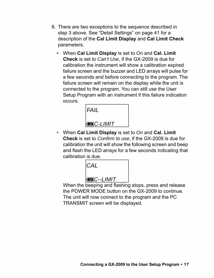
• When Cal Limit Display is set to On and Cal. Limit Check is set to Confirm to use, if the GX-2009 is due for calibration the unit will show the following screen and beep and flash the LED arrays for a few seconds indicating that calibration is due.
When the beeping and flashing stops, press and release the POWER MODE button on the GX-2009 to continue. The unit will now connect to the program and the PC TRANSMIT screen will be displayed.
FAIL
C-LIMIT
CAL
C--LIMIT
Connecting a GX-2009 to the User Setup Program • 17
7. There are two additional exceptions to the sequence described in step 3 above if the unit includes the bump test function and if Bump Limit Display is set to On. See “Detail Settings” on page 41 for a description of the Bump Limit Display and Bump Limit Check parameters.
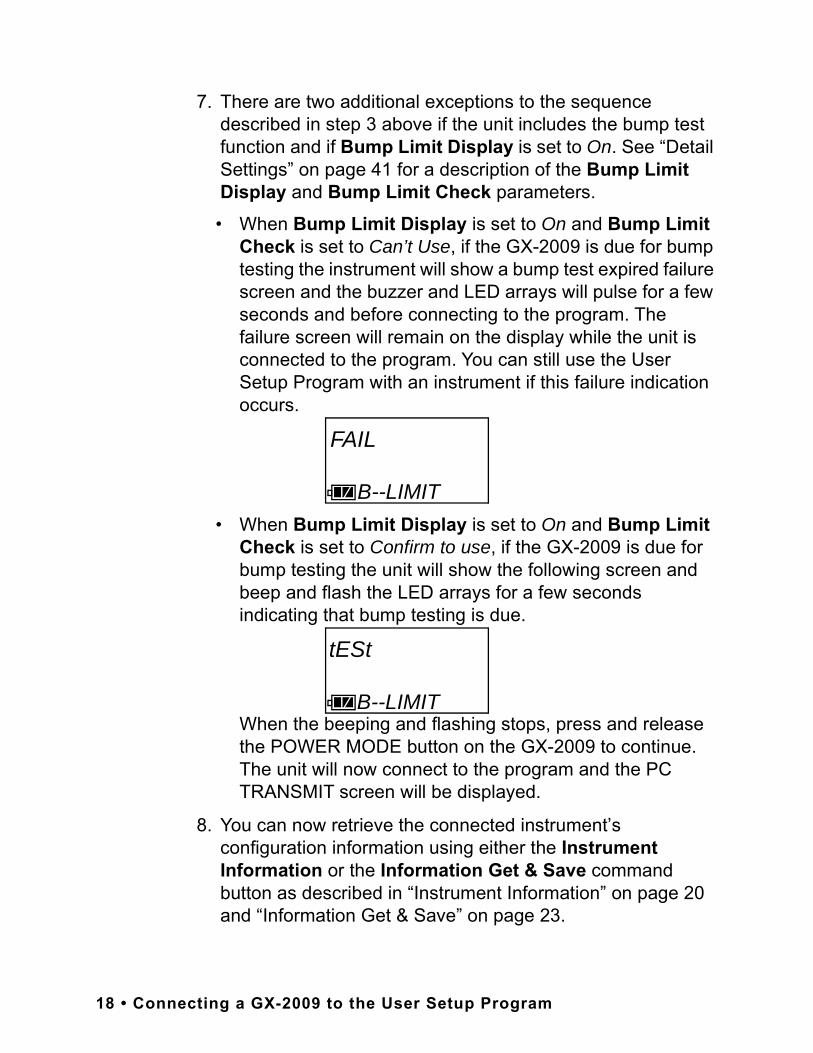
• When Bump Limit Display is set to On and Bump Limit Check is set to Can’t Use, if the GX-2009 is due for bump testing the instrument will show a bump test expired failure screen and the buzzer and LED arrays will pulse for a few seconds and before connecting to the program. The failure screen will remain on the display while the unit is connected to the program. You can still use the User Setup Program with an instrument if this failure indication occurs.
• When Bump Limit Display is set to On and Bump Limit Check is set to Confirm to use, if the GX-2009 is due for bump testing the unit will show the following screen and beep and flash the LED arrays for a few seconds indicating that bump testing is due.
When the beeping and flashing stops, press and release the POWER MODE button on the GX-2009 to continue. The unit will now connect to the program and the PC TRANSMIT screen will be displayed.
8. You can now retrieve the connected instrument’s configuration information using either the Instrument Information or the Information Get & Save command button as described in “Instrument Information” on page 20 and “Information Get & Save” on page 23.
FAIL
B--LIMIT
tESt
B--LIMIT
18 • Connecting a GX-2009 to the User Setup Program

You must retrieve the connected instrument’s configuration information before you can perform some operations such as saving the instrument’s parameter configuration to a file and changing the instruments parameter configuration.
The three basic command sets for performing these operations are the Read Commands, Write Commands, and Setting Commands. These command sets are described in the sections that follow.
Read Commands
Use the Read Commands to retrieve parameter configuration information from a GX-2009 and to save several of the instrument’s parameter settings and most recent calibration information to a .csv (comma separated value) file. The two Read Commands are Instrument Information and Information Get & Save.
Figure 11: Read Commands, Blanked Out
Read Commands • 19
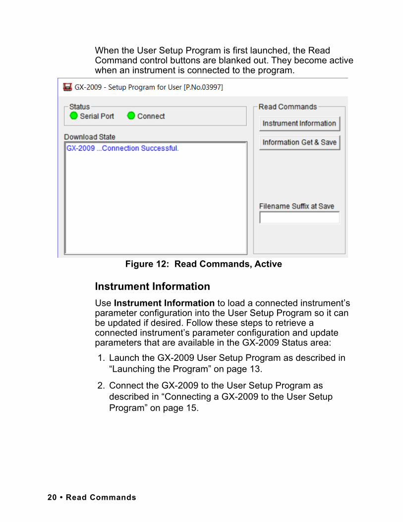
When the User Setup Program is first launched, the Read Command control buttons are blanked out. They become active when an instrument is connected to the program.
Instrument InformationUse Instrument Information to load a connected instrument’s parameter configuration into the User Setup Program so it can be updated if desired. Follow these steps to retrieve a connected instrument’s parameter configuration and update parameters that are available in the GX-2009 Status area: 1. Launch the GX-2009 User Setup Program as described in
“Launching the Program” on page 13.
2. Connect the GX-2009 to the User Setup Program as described in “Connecting a GX-2009 to the User Setup Program” on page 15.
Figure 12: Read Commands, Active
20 • Read Commands

3. With the Read Command Buttons now active, click Instrument Information to retrieve the instrument’s parameter configuration. The program indicates that it is downloading information from the instrument.
4. The instrument’s parameter configuration is now loaded in the User Setup Program and parameters are available for updating in the GX-2009 Status area of the Main Window and in the Factory Settings Window. The Factory Settings Window is accessed using the Detail Settings command button in Setting Commands. See “Detail Settings” on page 41 for a description of Detail Settings.
5. Various parameters are available for updating in the GX-2009 Status area. The fields for these parameters are white. Items in grey fields such as the Program Number and SUM cannot be edited. The following items can be changed:
• Serial No., Station ID, and User IDClick in the field and type in the desired string.
• Interval Trend TimeClick in the field. A drop down menu will appear. Select the desired value.
• Alarm Points & Auto Cal. ValueDouble click in the field and type in the desired setting.
• Enable StatusClick in an enable selection box to select or deselect the box. If the box is selected, the corresponding channel will be enabled when the change is uploaded to a GX-2009. If the box is deselected, the corresponding channel will be disabled when the change is uploaded.
Figure 13: Instrument Information Downloading
Read Commands • 21

6. Once you have made the desired parameter edits, click Update in the Write Commands.The following window appears prompting you to confirm that you want to make the update.
7. Click Yes to proceed. The program will indicate that it is uploading information to the GX-2009.
8. When the uploading is complete, the program will indicate that it is done.
9. Click OK. The program will return to the Main Window.
Figure 14: Update Window
Figure 15: Upload Window
Figure 16: Upload Complete Window
22 • Read Commands
Information Get & SaveUse Information Get & Save to load a connected instrument’s parameter configuration into the User Setup Program and edit parameters, just like Instrument Information. In addition, you can save an instrument’s parameter configuration and most recent calibration information to a .csv (comma separated value) file which can be opened with a spread sheet application such as Microsoft Excel. Follow these steps to retrieve a connected instrument’s parameter configuration, update parameters in the GX-2009 Status area, and save the parameter information and most recent calibration information to a .csv file: 1. Launch the GX-2009 User Setup Program as described in
“Launching the Program” on page 13.
2. Connect a GX-2009 to the User Setup Program as described in “Connecting a GX-2009 to the User Setup Program” on page 15. The Read Command buttons are now active and the Filename Suffix at Save field is available for entering a filename suffix.
3. Click in the Filename Suffix at Save field and enter a file name suffix.
When you use Instrument Get & Save, the program saves a connected instrument’s parameter configuration and most recent calibration information to a .csv file with the file name “GX2009_Setting[suffix].csv”.
You can add the instrument’s parameter configuration to an existing file or create a new file by using the Filename Suffix at Save field. The entered suffix is added to the end of the filename, before the file extension. If you do not type in a suffix, then the program will save the parameter configuration to the file “GX2009_Setting.csv”.
If the filename corresponds to an existing file, the program will add a connected instrument’s parameter configuration to the file.
If the filename does not exist, the program will create a new
Read Commands • 23
file and save the instrument’s parameter configuration to it. The suffix allows you to differentiate the .csv files from one another, such as between different instruments or between different downloads of the same instrument.
The file that the instrument’s parameter configuration is saved to by Instrument Get & Save is located in the User Setup Program’s folder on the computer’s C drive. The file path is: C:\Program Files\GX-2009UserConfig\GX2009_Setting[suffix].csv.
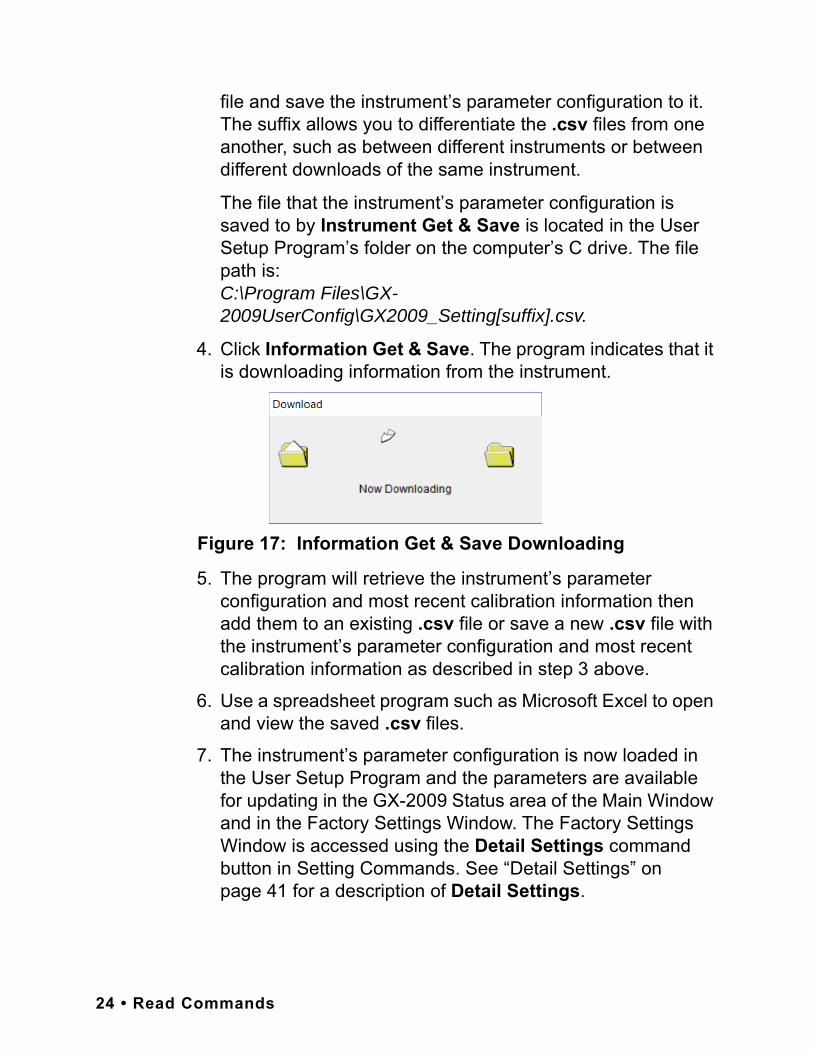
4. Click Information Get & Save. The program indicates that it is downloading information from the instrument.
5. The program will retrieve the instrument’s parameter configuration and most recent calibration information then add them to an existing .csv file or save a new .csv file with the instrument’s parameter configuration and most recent calibration information as described in step 3 above.
6. Use a spreadsheet program such as Microsoft Excel to open and view the saved .csv files.
7. The instrument’s parameter configuration is now loaded in the User Setup Program and the parameters are available for updating in the GX-2009 Status area of the Main Window and in the Factory Settings Window. The Factory Settings Window is accessed using the Detail Settings command button in Setting Commands. See “Detail Settings” on page 41 for a description of Detail Settings.
Figure 17: Information Get & Save Downloading
24 • Read Commands

8. See step 5 through step 9 in “Instrument Information” on page 20 for instructions to update parameters in the GX-2009 Status area of the Main Window.
Write Commands
Use the Write Commands to upload parameter changes and calibration adjustments to a connected instrument.The three Write Commands are Update, Date/Time Set, and Calibration.
When the User Setup program is first launched, the Write Command control buttons are blanked out. They become active when an instrument is connected to the program.
UpdateUse Update to upload changes that have been made to parameters in the GX-2009 Status Area of the Main Window or in the in the Factory Settings Window. The Factory Settings Window is accessed using the Detail Settings command button
Figure 18: Write Commands, Blanked Out
Figure 19: Write Commands, Active
Write Commands • 25
in Setting Commands. See “Detail Settings” on page 41 for a description of Detail Settings. When you click Update, any changes that have been made to a connected instrument’s parameters will be uploaded to the instrument. The use of Update at the appropriate time is described in various other sections in this manual.
Date/Time SetUse Date/Time Set to update the date and time in a connected instrument to match the computer’s date and time. Follow these steps to update an instrument’s date and time: 1. Launch the GX-2009 User Setup Program as described in
“Launching the Program” on page 13.
2. Connect the GX-2009 to the User Setup Program as described in “Connecting a GX-2009 to the User Setup Program” on page 15.
NOTE: It is not necessary to use Instrument Information or Instrument Get & Save in order to update the date and time. Although it is not necessary to use Instrument Information or Instrument Get & Save before updating the instrument’s date and time, you can update the date and time after using either of these commands if desired.
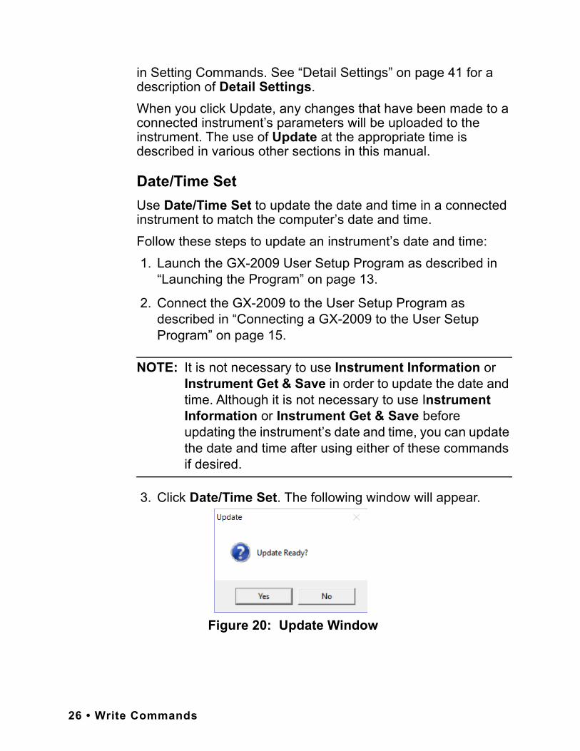
3. Click Date/Time Set. The following window will appear.
Figure 20: Update Window
26 • Write Commands

4. Click Yes. The program will update the instrument’s date and time to match the computer’s, then display the following window.
5. Click OK. The program will return to the Main Window.
CalibrationUse Calibration to calibrate an instrument by adjusting the instrument’s zero (fresh air) and span settings. Performing a span adjustment requires the use of a calibration kit. The procedure below describes a span adjustment of all four channels using a calibration kit that includes a 4-gas calibration cylinder, a 0.5 LPM (liters per minute) regulator, a calibration adapter plate, and non-absorbent sample tubing. The standard 4-gas cylinder consists of 50% LEL methane, 12% oxygen, 25 ppm H2S, 50 ppm CO, and a balance of nitrogen. If the H2S channel on your GX-2009 is active, then use a 4-gas cylinder. If the H2S channel on your GX-2009 is not active, you may use a 3-gas cylinder to adjust the span. The standard 3-gas cylinder consists of 50% LEL methane, 12% oxygen, 50 ppm CO, and a balance of nitrogen. See “Spare Parts List” on page 52 for available calibration kits and calibration kit spare parts.The area where you perform the calibration must be a fresh air environment, an environment of normal oxygen content (20.9%) that is free of toxic and combustible gases. Typical desktop computer locations such as an office or laboratory are fresh air environments, but if you are in the field using a laptop to calibrate an instrument, be sure to confirm that the area is a fresh air environment.
Figure 21: Upload Complete Window
Write Commands • 27
Follow these steps to calibrate an instrument: 1. Confirm that the area where you will perform the calibration
is a fresh air environment.
2. Launch the GX-2009 User Setup Program as described in “Launching the Program” on page 13.
3. Connect the GX-2009 to the User Setup Program as described in “Connecting a GX-2009 to the User Setup Program” on page 15.
NOTE: It is not necessary to use Instrument Information or Instrument Get & Save in order to perform a calibration. Although it is not necessary to use Instrument Information or Instrument Get & Save before performing a calibration, you can perform a calibration after using these either of these commands if desired.
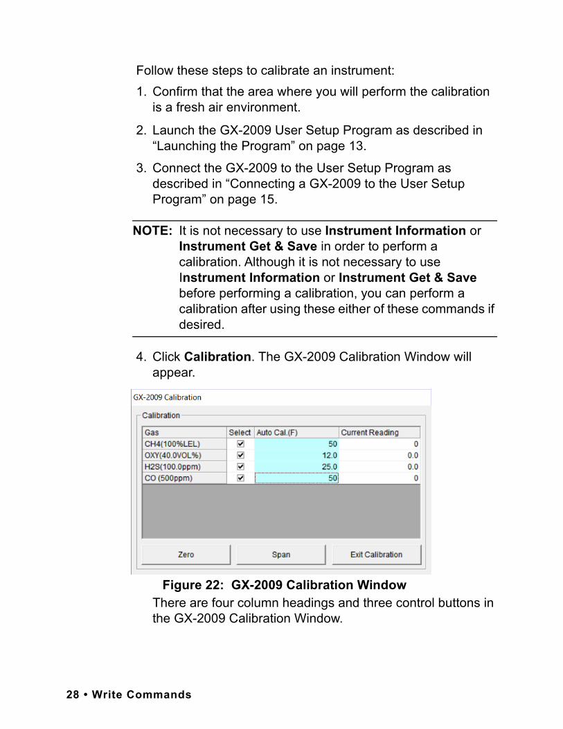
4. Click Calibration. The GX-2009 Calibration Window will appear.
There are four column headings and three control buttons in the GX-2009 Calibration Window.
Figure 22: GX-2009 Calibration Window
28 • Write Commands
• GasThe Gas column shows the four detection channels, the target gas for each channel, and the detection range full scale value for each channel.
• SelectThe Select column has a selection box for each channel that allows you to select or deselect a channel for zero and span adjustments.
• Auto Cal.The Auto Cal. column displays the auto calibration values for each channel. These values are retrieved from an instrument when a connection is established. They cannot be changed in the Calibration Window.
• Current ReadingThe Current Reading column displays the current real time gas reading for each channel.
• Zero ButtonClick Zero at the appropriate time to perform a zero (fresh air) adjustment on the instrument’s selected channels.
• Span ButtonClick Span at the appropriate time to perform a span adjustment on the instrument’s selected channels.
• Exit Calibration ButtonClick Exit Calibration to close the GX-2009 Calibration Window and return to the Main Window.
Write Commands • 29
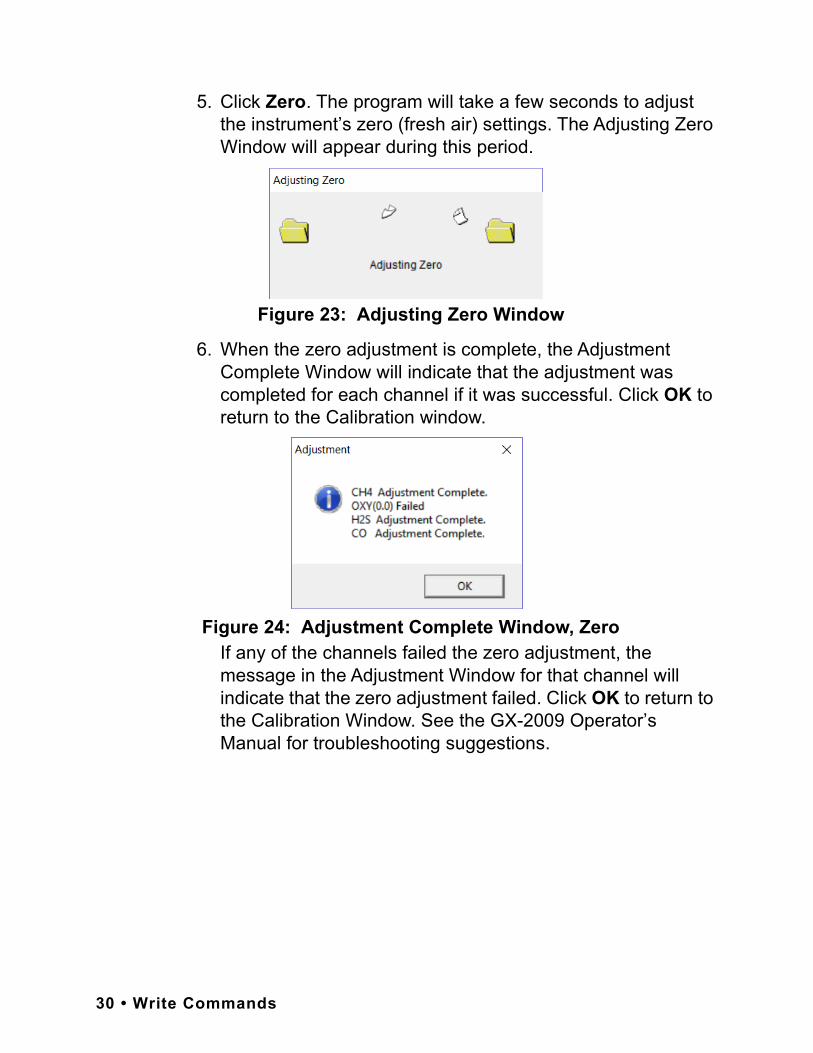
5. Click Zero. The program will take a few seconds to adjust the instrument’s zero (fresh air) settings. The Adjusting Zero Window will appear during this period.
6. When the zero adjustment is complete, the Adjustment Complete Window will indicate that the adjustment was completed for each channel if it was successful. Click OK to return to the Calibration window.
If any of the channels failed the zero adjustment, the message in the Adjustment Window for that channel will indicate that the zero adjustment failed. Click OK to return to the Calibration Window. See the GX-2009 Operator’s Manual for troubleshooting suggestions.
Figure 23: Adjusting Zero Window
Figure 24: Adjustment Complete Window, Zero
30 • Write Commands

7. Use the calibration kit sample tubing to connect the calibration adapter plate to the regulator. Attach the tubing to the adapter plate on the inlet side as shown below in Figure 25.
8. Confirm that the regulator on/off knob is turned all the way clockwise (closed) and screw the calibration gas cylinder onto the regulator.
9. Hold the GX-2009 in place with one hand while pushing the adapter plate onto the GX-2009’s sensor face with the other to avoid moving the GX-2009 excessively and losing the connection to the computer. Make sure the adapter plate is oriented as shown in Figure 26 below with the sensor names on the adapter plate matching up with the sensor names on the instrument.
O2
CO
Flow
To Fixed FlowRegulator
Calibration TubingT
Tu bin g
Adapter Plate
%LE
L
H2S
Figure 25: Calibration Kit Assembly
Write Commands • 31

Figure 26: Installing the Adapter Plate, Auto Cal
10.Turn the regulator on/off knob counterclockwise to open it. Calibration gas will begin to flow.
11.Allow the gas to flow for two minutes.
12.Click Span. The program will take a few seconds to adjust the instrument’s span settings. The Adjusting Span Window will appear during this period.
Flow
%LE
L
H2S
O2
To Fixed FlowRegulator
CO
AIR POWERMODE
RKI GX-2009
H2S CO %LEL O2
Adapter Plate
Figure 27: Adjusting Span Window
32 • Write Commands
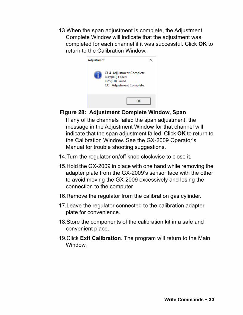
13.When the span adjustment is complete, the Adjustment Complete Window will indicate that the adjustment was completed for each channel if it was successful. Click OK to return to the Calibration Window.
If any of the channels failed the span adjustment, the message in the Adjustment Window for that channel will indicate that the span adjustment failed. Click OK to return to the Calibration Window. See the GX-2009 Operator’s Manual for trouble shooting suggestions.
14.Turn the regulator on/off knob clockwise to close it.
15.Hold the GX-2009 in place with one hand while removing the adapter plate from the GX-2009’s sensor face with the other to avoid moving the GX-2009 excessively and losing the connection to the computer
16.Remove the regulator from the calibration gas cylinder.
17.Leave the regulator connected to the calibration adapter plate for convenience.
18.Store the components of the calibration kit in a safe and convenient place.
19.Click Exit Calibration. The program will return to the Main Window.
Figure 28: Adjustment Complete Window, Span
Write Commands • 33
Setting Commands
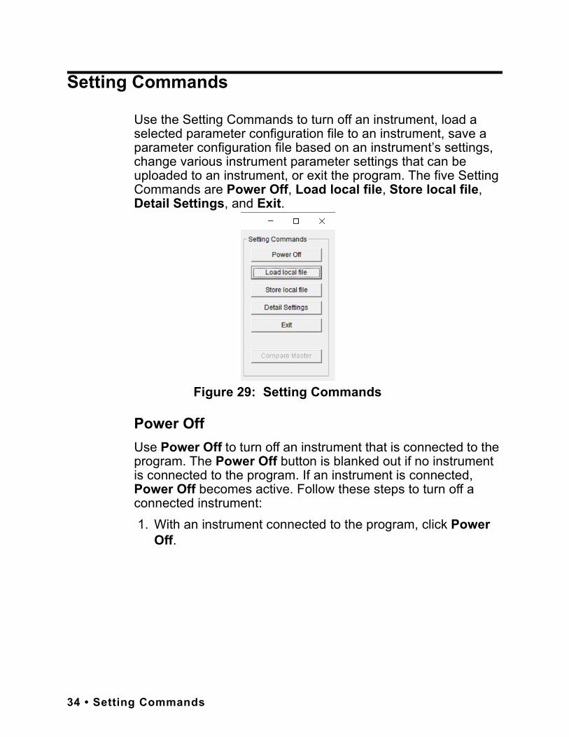
Use the Setting Commands to turn off an instrument, load a selected parameter configuration file to an instrument, save a parameter configuration file based on an instrument’s settings, change various instrument parameter settings that can be uploaded to an instrument, or exit the program. The five Setting Commands are Power Off, Load local file, Store local file, Detail Settings, and Exit.
Power OffUse Power Off to turn off an instrument that is connected to the program. The Power Off button is blanked out if no instrument is connected to the program. If an instrument is connected, Power Off becomes active. Follow these steps to turn off a connected instrument: 1. With an instrument connected to the program, click Power
Off.
Figure 29: Setting Commands
34 • Setting Commands
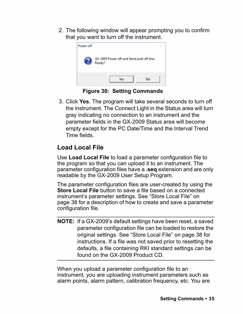
2. The following window will appear prompting you to confirm that you want to turn off the instrument.
3. Click Yes. The program will take several seconds to turn off the instrument. The Connect Light in the Status area will turn gray indicating no connection to an instrument and the parameter fields in the GX-2009 Status area will become empty except for the PC Date/Time and the Interval Trend Time fields.
Load Local FileUse Load Local File to load a parameter configuration file to the program so that you can upload it to an instrument. The parameter configuration files have a .seq extension and are only readable by the GX-2009 User Setup Program. The parameter configuration files are user-created by using the Store Local File button to save a file based on a connected instrument’s parameter settings. See “Store Local File” on page 38 for a description of how to create and save a parameter configuration file.
NOTE: If a GX-2009’s default settings have been reset, a saved parameter configuration file can be loaded to restore the original settings. See “Store Local File” on page 38 for instructions. If a file was not saved prior to resetting the defaults, a file containing RKI standard settings can be found on the GX-2009 Product CD.
When you upload a parameter configuration file to an instrument, you are uploading instrument parameters such as alarm points, alarm pattern, calibration frequency, etc. You are
Figure 30: Setting Commands
Setting Commands • 35
also uploading user and station ID information. Uploading a parameter configuration file to an instrument will not change the instrument’s serial number.Follow these steps to load a parameter configuration file to the program and upload it to an instrument: 1. Launch the GX-2009 User Setup Program as described in
“Launching the Program” on page 13.
2. Connect the GX-2009 to the User Setup Program as described in “Connecting a GX-2009 to the User Setup Program” on page 15.
NOTE: It is not necessary to use Instrument Information or Instrument Get & Save in order to load a parameter configuration file and upload it to an instrument. Although it is not necessary to use Instrument Information or Instrument Get & Save before loading a file and uploading it to an instrument, you can do so after using either of these functions if desired.
36 • Setting Commands

3. Click Load local file. The Open Window will appear allowing you to navigate to a file location and select a file to load.
4. Use the Open Window to navigate to the location of the file you wish to load.
5. Select the file you wish to load and click Open. The program will load the parameter configuration file and all of the parameter fields that can be uploaded from a parameter configuration file will be populated by the file’s settings.
6. Click Update in the Write Commands. The Update Window will appear prompting you to confirm that you want to update the instrument.
Figure 31: Open Window
Figure 32: Update Window
Setting Commands • 37
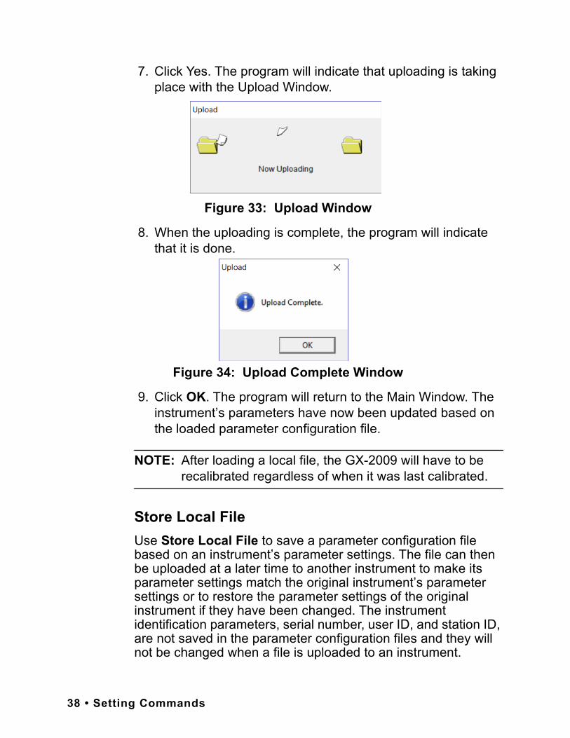
7. Click Yes. The program will indicate that uploading is taking place with the Upload Window.
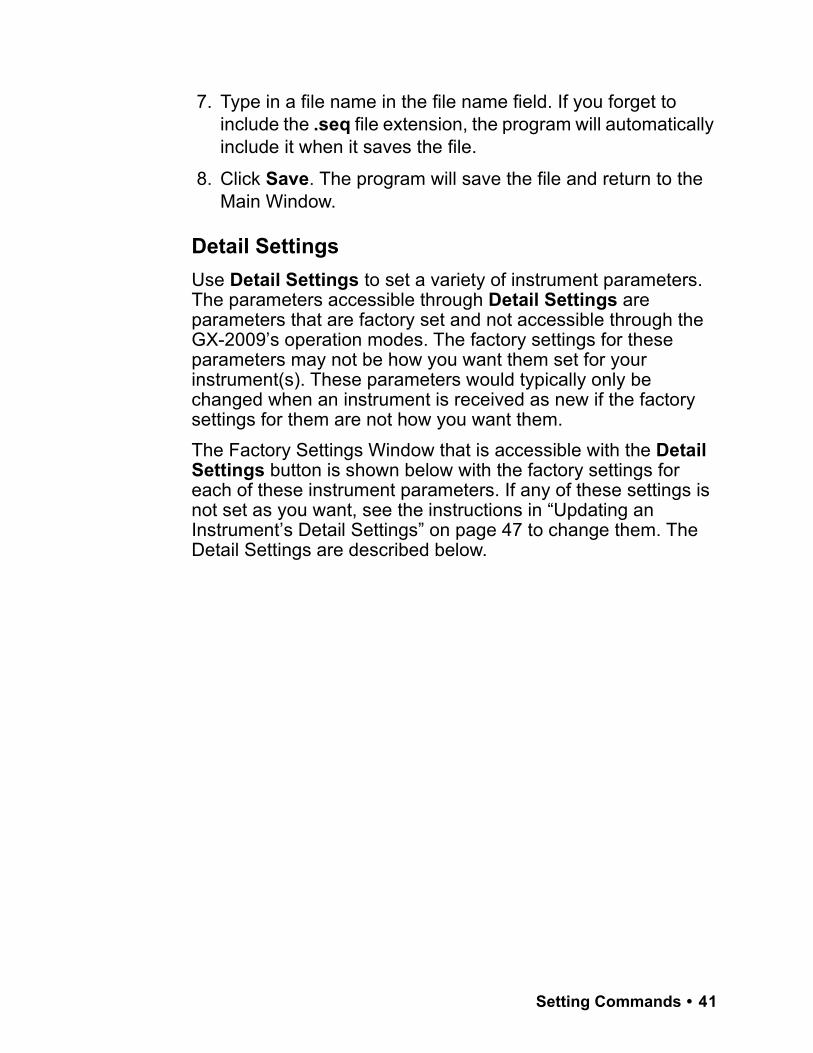
8. When the uploading is complete, the program will indicate that it is done.
9. Click OK. The program will return to the Main Window. The instrument’s parameters have now been updated based on the loaded parameter configuration file.
NOTE: After loading a local file, the GX-2009 will have to be recalibrated regardless of when it was last calibrated.
Store Local FileUse Store Local File to save a parameter configuration file based on an instrument’s parameter settings. The file can then be uploaded at a later time to another instrument to make its parameter settings match the original instrument’s parameter settings or to restore the parameter settings of the original instrument if they have been changed. The instrument identification parameters, serial number, user ID, and station ID, are not saved in the parameter configuration files and they will not be changed when a file is uploaded to an instrument.
Figure 33: Upload Window
Figure 34: Upload Complete Window
38 • Setting Commands

A parameter configuration file that contains your specific configuration information should be saved in case consultation with the factory determines that the instrument’s default settings need to be reset.
NOTE: Consult RKI Instruments, Inc. before resetting the GX-2009’s default settings.
Once the defaults have been reset, the saved parameter configuration file can be loaded into the GX-2009 as described in “Load Local File” on page 35. A parameter configuration file containing RKI standard settings can be found on the GX-2009 Product CD and can be used after a default reset if a parameter configuration file was not saved. Once the RKI standard setting file is loaded, the settings can be changed to match the original configuration of the GX-2009.The parameter configuration files that are created have a .seq file extension. These files can only be used by the User Setup Program. When you use Store Local File, you can save the created files to any accessible location on your hard drive. Make sure to define a convenient location on your hard drive for these files if you use this feature so that you can conveniently find them when you want to upload a file to an instrument. When you select names for these files, you may want to structure the file names so you can identify from which instrument the file was saved or so that you can identify a particular parameter configuration. Structure the file names so that you can easily identify the files as containing the information that is important to you.Follow these steps to create a parameter configuration file based on a connected instrument: 1. Launch the GX-2009 User Setup Program as described in
“Launching the Program” on page 13.
2. Connect the GX-2009 to the User Setup Program as described in “Connecting a GX-2009 to the User Setup Program” on page 15.
Setting Commands • 39

3. With the Read Command Buttons now active, click Instrument Information to retrieve the instrument’s parameter configuration. The program indicates that it is downloading information from the instrument.
4. The instrument’s parameter configuration is now loaded in the User Setup Program.
5. Click Store local file. The Save As Window will appear allowing you to navigate to a file location and save a file to the selected location.
6. Use the Save As Window to navigate to the location where you want to save the file.
Figure 35: Instrument Information Downloading
Figure 36: Save As Window
40 • Setting Commands
7. Type in a file name in the file name field. If you forget to include the .seq file extension, the program will automatically include it when it saves the file.
8. Click Save. The program will save the file and return to the Main Window.
Detail SettingsUse Detail Settings to set a variety of instrument parameters. The parameters accessible through Detail Settings are parameters that are factory set and not accessible through the GX-2009’s operation modes. The factory settings for these parameters may not be how you want them set for your instrument(s). These parameters would typically only be changed when an instrument is received as new if the factory settings for them are not how you want them.The Factory Settings Window that is accessible with the Detail Settings button is shown below with the factory settings for each of these instrument parameters. If any of these settings is not set as you want, see the instructions in “Updating an Instrument’s Detail Settings” on page 47 to change them. The Detail Settings are described below.
Setting Commands • 41
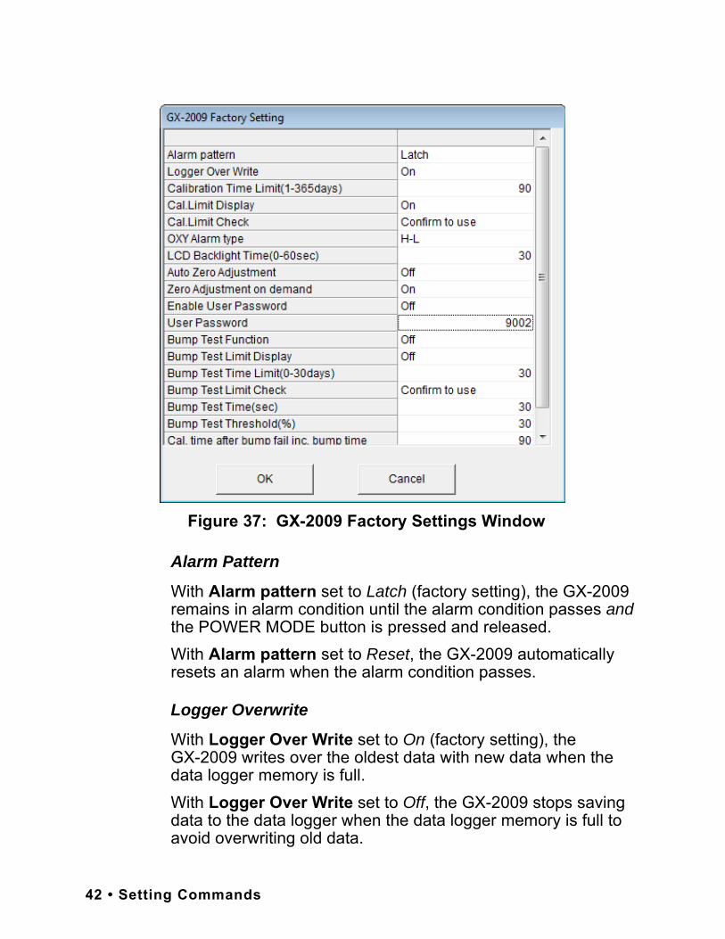
Alarm Pattern
With Alarm pattern set to Latch (factory setting), the GX-2009 remains in alarm condition until the alarm condition passes and the POWER MODE button is pressed and released.With Alarm pattern set to Reset, the GX-2009 automatically resets an alarm when the alarm condition passes.
Logger Overwrite
With Logger Over Write set to On (factory setting), theGX-2009 writes over the oldest data with new data when the data logger memory is full.With Logger Over Write set to Off, the GX-2009 stops saving data to the data logger when the data logger memory is full to avoid overwriting old data.
Figure 37: GX-2009 Factory Settings Window
42 • Setting Commands
Calibration Time Limit
This setting defines the amount of time between calibrations. The minimum setting is 1 day and the maximum setting is 365 days. The factory setting is 90 days.
Cal. Limit Display
With Cal. Limit Display set to On (factory setting), the GX-2009 will give an indication at start up if it is due for calibration. The type of indication will depend on the Cal. Limit Check setting (see next item below).With Cal. Limit Display set to OFF, if an instrument is due for calibration, it will give no indication at startup that it is due for calibration.
Cal. Limit Check
This item defines what indication is given during start up when calibration is due and Cal. Limit Display is set to On.With Cal. Limit Check set to Confirm to use (factory setting), the GX-2009 will give an indication at start up if calibration is due and require the user to press and release the POWER MODE button to continue.With Cal. Limit Check set to Can’t use, if the unit is due for calibration the GX-2009 will give an indication at start up that calibration is due and the unit cannot be used until it is calibrated. With this setting, it is necessary to calibrate the instrument before it can be used. You may calibrate the instrument using the User Setup Program or the GX-2009’s Calibration Mode or User Setup Mode. See “Calibration” on page 27 for instructions to calibrate an instrument using the User Setup Program. See the GX-2009 Operator’s Manual for instructions to calibrate an instrument using Calibration Mode or User Setup Mode.With Cal. Limit Check set to None, no confirmation during startup or calibration is required to use the GX-2009 if it is past due for calibration.
Setting Commands • 43
LCD Backlight Time
This setting indicates the length of time the LCD backlight is on after when you press any button. The minimum setting is 0 seconds. The maximum setting is 60 seconds. The factory setting is 30 seconds.
Auto Zero Adjustment
With Auto Zero Adjustment set to Off (factory setting), no automatic fresh air adjustment will take place during aGX-2009’s startup sequence when it is turned on.With Auto Zero Adjustment set to On, the GX-2009 will perform an automatic fresh air adjustment during the startup sequence when it is turned on.
Zero Adjustment On Demand
With Zero Adjustment on demand set to On (factory setting), you can perform a fresh air adjustment in Measuring Mode by using the GX-2009’s AIR button.With Zero Adjustment on demand set to Off, the GX-2009’s AIR button is not operational in Measuring Mode, so it is not possible to perform a fresh air adjustment in Measuring Mode. You can still perform a fresh air adjustment in Calibration Mode and User Setup Mode.
Enable User Password
With Enable User Password set to On, the GX-2009 prompts you for a password when you enter Calibration Mode or User Setup Mode.With Enable User Password set to Off (factory setting), no password is required to enter Calibration Mode or User Setup Mode.
User Password
User Password allows you to define the password that allows you to enter Calibration Mode or User Setup Mode if Enable User Password is set to On.
44 • Setting Commands
Bump Test Function
This item turns the bump test function on or off (factory setting). With Bump Test Function set to On, the BUMP item will appear in the Calibration Mode menu. This menu item allows you to bump test the GX-2009. With Bump Test Function set to Off (factory setting), the BUMP item will not appear in the Calibration Mode menu.
Bump Test Limit Display
With Bump Test Limit Display set to On, the GX-2009 will give an indication at start up if it is due for bump testing. The type of indication will depend on the Bump Test Limit Check setting.
NOTE: If Bump Test Function is set to Off and the Bump Test Limit Display is set to On, the GX-2009 will still alert you during the startup sequence when a bump test is due.
With Bump Test Limit Display set to OFF (factory setting), if an instrument is due for bump testing, it will give no indication at startup that it is due for bump testing.
Bump Test Time Limit
This setting defines the amount of time between bump tests. The minimum setting is 0 days and the maximum setting is 30 days. If it is set for 0 days, a bump test will always be due. The factory setting is 30 days.
NOTE: If a successful calibration is performed, the next bump test date is reset and starts over even though a bump test was not performed.
Setting Commands • 45
Bump Test Limit Check
This item defines what indication is given during start up when bump testing is due and Bump Test Limit Display is set to On.With Bump Test Limit Check set to Confirm to use (factory setting), the GX-2009 will give an indication at start up if bump testing is due and require the user to press and release the POWER MODE button to continue.With Bump Test Limit Check set to Can’t use, if the unit is due for bump testing the GX-2009 will give an indication at start up that bump testing is due and the unit cannot be used until it is bump tested. With this setting, it is necessary to bump test the instrument before it can be used. You may bump test the instrument using the BUMP menu item in Calibration Mode.With Bump Test Limit Check set to None, no confirmation during startup or bump testing is required to use the GX-2009 if it is past due for bump testing.
Bump Test Time
Length of time gas is applied during a bump test. The factory setting is 30 seconds.
Bump Test Threshold
Percentage that the gas reading may differ from actual gas value to pass a bump test. The factory setting is 30%.
Cal. Time After Bump Fail Inc. Bump Time
Length of time gas is applied during calibration after a bump test has failed if Calibration after Bump Test Failed is set to On. The factory setting is 90 seconds. This time includes the time that the unit was being bump tested. If Cal. Time After Bump Fail Inc. Bump Time is set to 90 seconds and the Bump Test Time is set to 30 seconds, the unit will sample gas for an additional 60 seconds if the bump test fails to bring the total exposure time to 90 seconds.
46 • Setting Commands
Calibration After Bump Test Failed
Calibration automatically begins after a failed bump test if set to On (factory setting).
Updating an Instrument’s Detail SettingsFollow these steps to update an instrument’s detail settings: 1. Launch the GX-2009 User Setup Program as described in
“Launching the Program” on page 13.
2. Connect the GX-2009 to the User Setup Program as described in “Connecting a GX-2009 to the User Setup Program” on page 15.
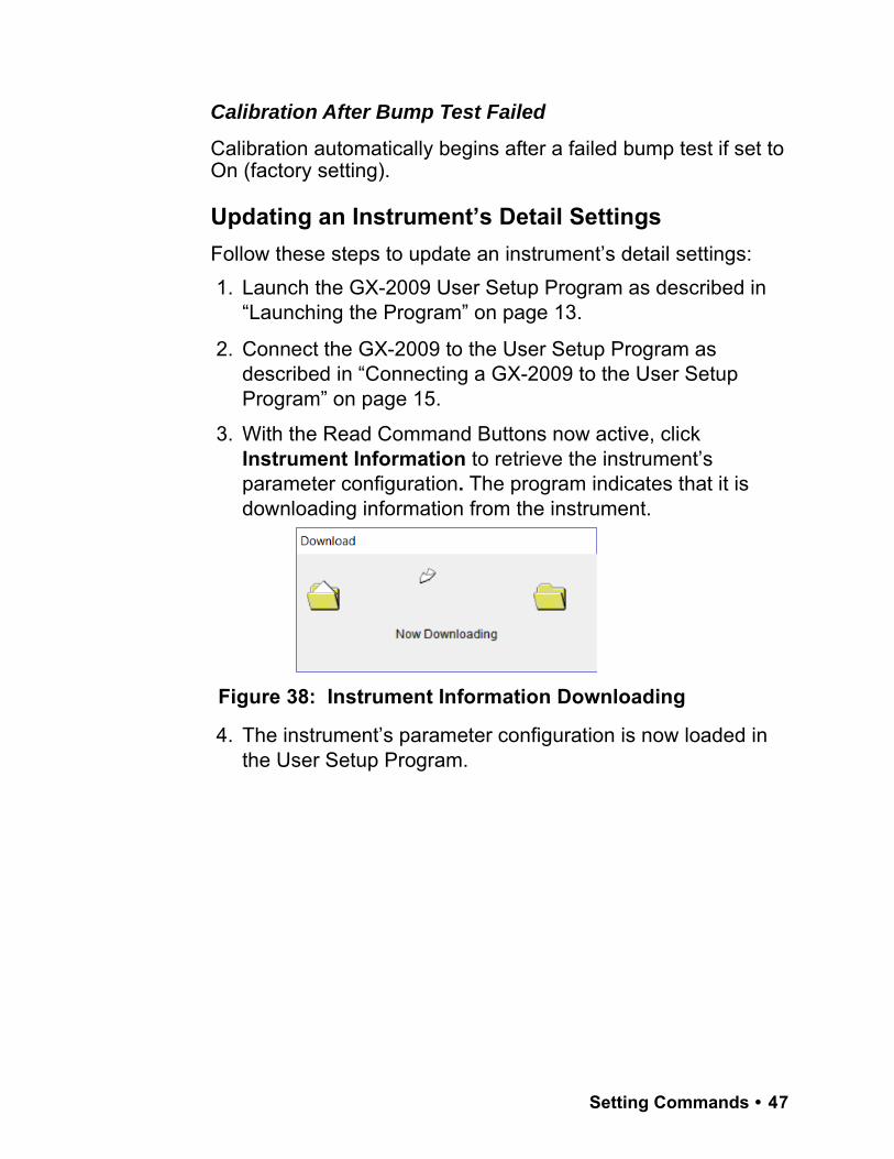
3. With the Read Command Buttons now active, click Instrument Information to retrieve the instrument’s parameter configuration. The program indicates that it is downloading information from the instrument.
4. The instrument’s parameter configuration is now loaded in the User Setup Program.
Figure 38: Instrument Information Downloading
Setting Commands • 47
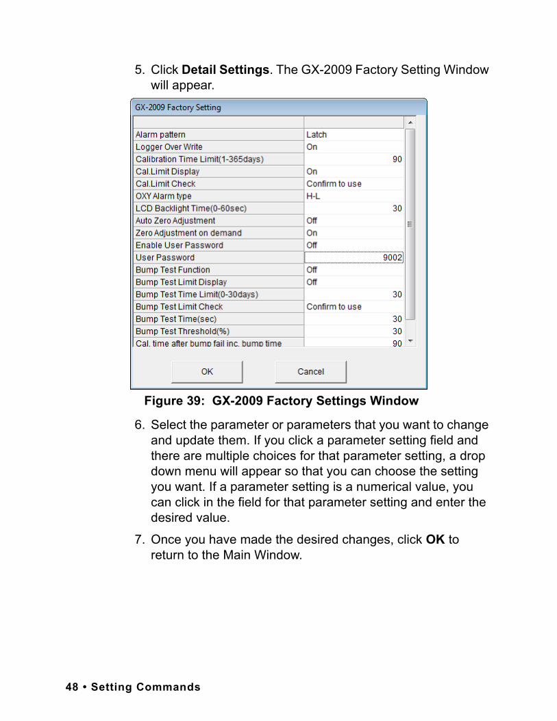
5. Click Detail Settings. The GX-2009 Factory Setting Window will appear.
6. Select the parameter or parameters that you want to change and update them. If you click a parameter setting field and there are multiple choices for that parameter setting, a drop down menu will appear so that you can choose the setting you want. If a parameter setting is a numerical value, you can click in the field for that parameter setting and enter the desired value.
7. Once you have made the desired changes, click OK to return to the Main Window.
Figure 39: GX-2009 Factory Settings Window
48 • Setting Commands
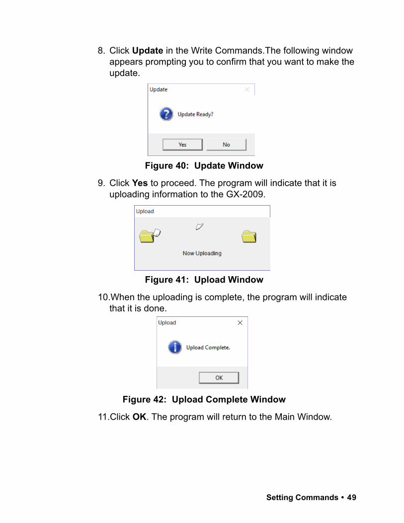
8. Click Update in the Write Commands.The following window appears prompting you to confirm that you want to make the update.
9. Click Yes to proceed. The program will indicate that it is uploading information to the GX-2009.
10.When the uploading is complete, the program will indicate that it is done.
11.Click OK. The program will return to the Main Window.
Figure 40: Update Window
Figure 41: Upload Window
Figure 42: Upload Complete Window
Setting Commands • 49
ExitClick Exit to shut down the User Setup Program. If an instrument is connected to the program, make sure to turn off the instrument before shutting down the program to avoid leaving the instrument on in PC Mode and draining the battery.
Compare MasterThe Compare Master button is useful for checking an instrument’s parameters against a loaded file. The most useful way to use this feature is to save a local file from an instrument set up with standard settings (as described in “Store Local File” on page 38). That file can then be used to check all other instruments that should have the same standard settings. 1. Launch the GX-2009 User Setup Program as described in
“Launching the Program” on page 13.
2. Load a local file as described in step 3 - step 5 on page 37.
3. Connect the GX-2009 to the User Setup Program as described in “Connecting a GX-2009 to the User Setup Program” on page 15.
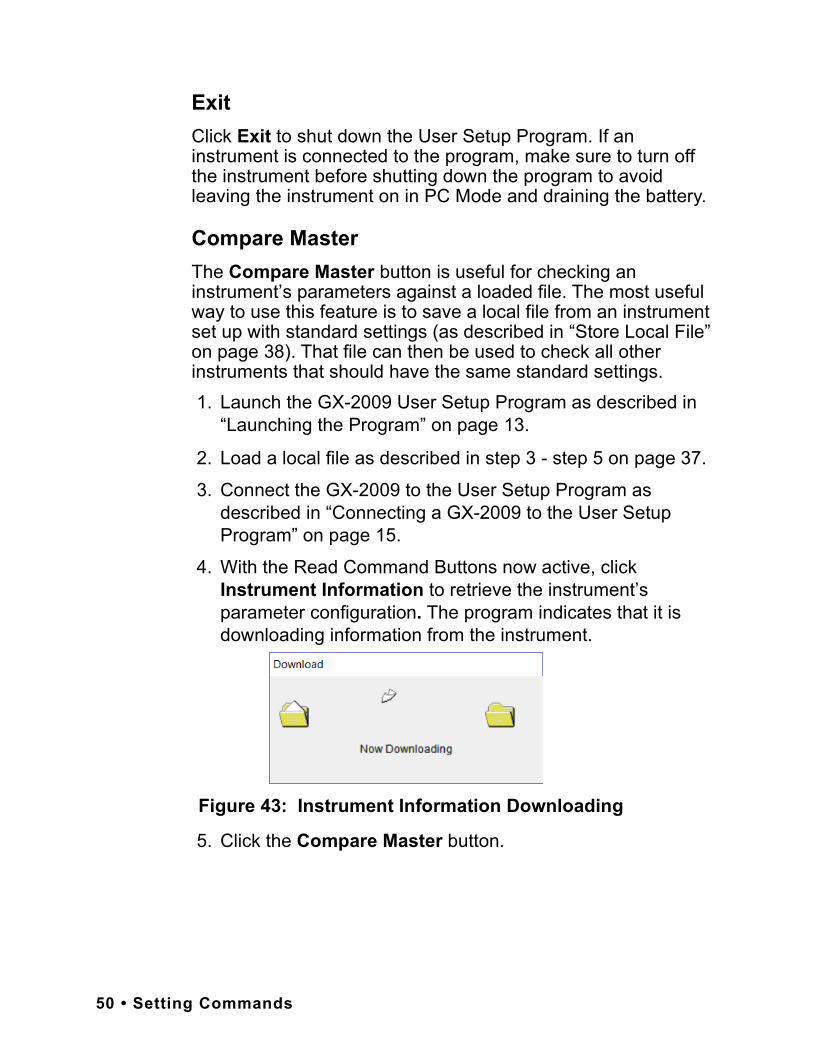
4. With the Read Command Buttons now active, click Instrument Information to retrieve the instrument’s parameter configuration. The program indicates that it is downloading information from the instrument.
5. Click the Compare Master button.
Figure 43: Instrument Information Downloading
50 • Setting Commands
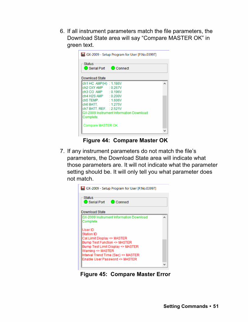
6. If all instrument parameters match the file parameters, the Download State area will say “Compare MASTER OK” in green text.
7. If any instrument parameters do not match the file’s parameters, the Download State area will indicate what those parameters are. It will not indicate what the parameter setting should be. It will only tell you what parameter does not match.
Figure 44: Compare Master OK
Figure 45: Compare Master Error
Setting Commands • 51

8. To rectify the situation, load the local file again and click Update.
NOTE: If a local file is updated, the instrument will have to be recalibrated.
Spare Parts List
Table 1: Spare Parts List
Part Number Description
06-1248RK-03 Calibration kit tubing, 3 foot length
47-5084RK USB/IrDA adapter module (without USB cable)
47-5084RK-01 USB/IrDA adapter assembly (with module and USB cable)
47-5085RK Cable, USB A to USB mini, 6 feet, for USB/IrDA adaptermodule
71-0158RK GX-2009 Operator’s Manual
71-0162RK GX-2009 User Setup Program Operator’s Manual (this document)
71-8002RK GX-2009 Product CD, Includes the GX-2009 Data Logger Management Program, the GX-2009 User Setup Program, and Operator’s Manuals for Each
81-GX01HSCO One 58 ltr. aluminum cylinder, regulator, calibration plate, case & tubing
81-GX01HSCO-LV One 34 ltr. aluminum cylinder, regulator, calibration plate, case & tubing
81-GX01CO One 103 ltr. cylinder, regulator, calibration plate, case &tubing
81-GX01CO-LV One 34 ltr. steel cylinder, regulator, calibration plate, case & tubing
52 • Spare Parts List
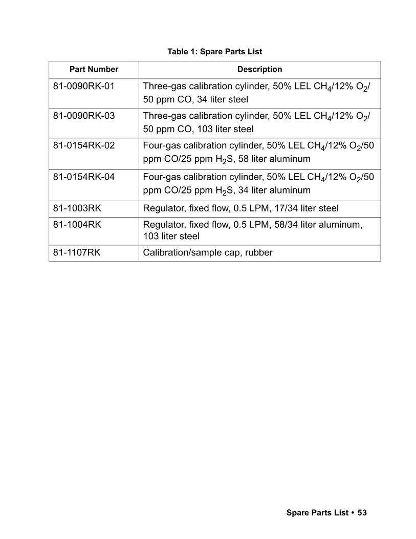
81-0090RK-01 Three-gas calibration cylinder, 50% LEL CH4/12% O2/50 ppm CO, 34 liter steel
81-0090RK-03 Three-gas calibration cylinder, 50% LEL CH4/12% O2/50 ppm CO, 103 liter steel
81-0154RK-02 Four-gas calibration cylinder, 50% LEL CH4/12% O2/50ppm CO/25 ppm H2S, 58 liter aluminum
81-0154RK-04 Four-gas calibration cylinder, 50% LEL CH4/12% O2/50ppm CO/25 ppm H2S, 34 liter aluminum
81-1003RK Regulator, fixed flow, 0.5 LPM, 17/34 liter steel
81-1004RK Regulator, fixed flow, 0.5 LPM, 58/34 liter aluminum, 103 liter steel
81-1107RK Calibration/sample cap, rubber
Table 1: Spare Parts List
Part Number Description
Spare Parts List • 53