h 7 3 2 4 r 7 7 nasa technical nasa tmx- 68249
TRANSCRIPT
H 7 3 2 4 R 7 7
NASA T E C H N I C A LMEMO RANDU M
NASA TMX- 68249
CVI
<t/»<
TITAN/CENTAUR - NASA'S NEWEST LAUNCH VEHICLE
by Andrew J. StofanLewis Research CenterCleveland, Ohio 44135
TECHNICAL PAPER proposed for presentation atSpace Mission Planning and Executive Meeting for theLaunch Vehicle Issues Section sponsored by theAmerican Institute of Aeronautics and Astronautics,American Society of Mechanical Engineers, and theSociety of Automotive EngineersDenver, Colorado, July 10-11, 1973
TITAN/CENTAUR — NASA'S NEWEST LAUNCH VEHICLE
Andrew J. StofanManager, Titan/Centaur Project Office
National Aeronautics and Space AdministrationLewis Research Center
Cleveland, Ohio
inoinr-
iW
Abstract
Titan/Centaur is NASA's last "new-expendable"launch vehicle prior to the advent of the SpaceShuttle. Titan/Centaur is an adaptation of theAir Force Titan III booster with an improved ver-sion of the Centaur stage and a new 4.2 meters (14feet) payload fairing. Titan/Centaur is i n i t i a l l ybeing used for high performance escape missions(Helios Solar Probe - 340 kilograms (750 pounds),Viking Mars Orbiter and Lander - 3,629 kilograms(8,000 pounds), and Mariner Jupiter/Saturn Fly-Bysat 771 kilograms (1,700 pounds)) but is also partic-ularly suited for larger spacecraft in synchronousorbits (transfer - 7,031 kilograms (15,500 pounds)and equatorial-, with three Cuntaur burns - 3,175kilograms (7,000 pounds)). The program which beganin 1965 with internal NASA f e a s i b i l i t y studies w i l lculminate in a "Proof Flight" launch in early 1974.With the new payload fairing, which also enclosesCentaur, paylosds of nearly 8.5 meters (28 feet)long and 3.8 meters (12-1/2 feet) in diameter canbe accommodated.
Culminating over five years of intensive plan-ning, engineering, development, testing, launchsite modifications, and hardware fabrication,NASA's proof fl i g h t of the Titan/Centaur launchvehicle is rapidly approaching.
Introduction
A little over a decade ago the Centaur programpioneered the use of high energy vehicles fueledwith l i q u i d oxygen and l i q u i d hydrogen. Centaurhas flown successfully with the Atlas booster de-livering payloads to earth orbit, synchronoustransfer orbit, and lunar and planetary trajec-tories .
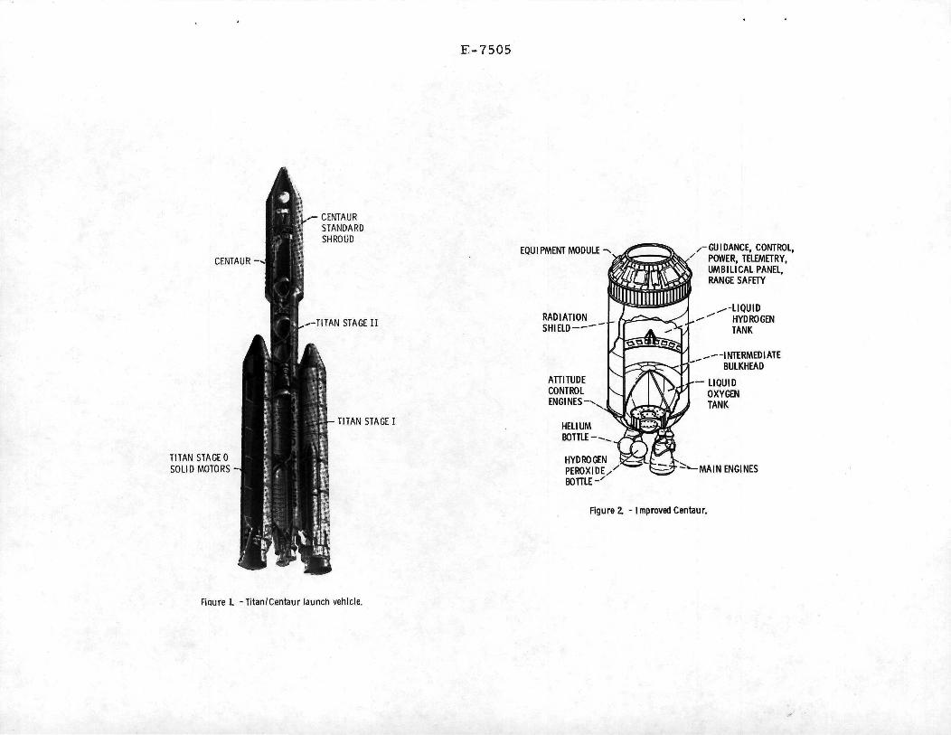
The earlier version of Centaur has been im-proved and integrated with the modified Atlasbooster. This Atlas/Improved Centaur launch ve-hicle system proved itself April 5, 1973, byplacing the Pioneer 11 spacecraft on the propertrajectory to the planet Jupiter. The ImprovedCentaur is currently being integrated with theUnited States Air Force (USAF) Titan III boosterand a new shroud system. The configuration ofthis new Titan/Centaur launch vehicle is shown inFigure 1. The overall length is 48.8 meters (160feet) with a total lift-off weight of 6.4 X IflSkilograms (1.4 X 10° pounds). The Titan/Centaurw i l l be used to launch operational payloads suchas Helios, a joint undertaking between NASA andthe Federal Republic of Germany Space Agency toinvestigate space near the sun; Viking, a combi-nation Martian orbiter and lander, and MarinerJupiter/Saturn, a fly-by of these planets.
The effort to integrate the Titan with theCentaur began in the mid-sixties. NASA-Lewis Re-search Center studies were conducted to define anImproved Centaur vehicle and to integrate the Cen-taur with the USAF Titan III booster. This devel-opment was undertaken because NASA recognized theneed to fill a performance and cost gap between theAtlas/Centaur and Saturn launch vehicles. Theunique capabilities of the Titan/Centaur, whichprovide a high energy restartable upper stage, f i l lthe need for a launch vehicle capable of deliveringlarger and heavier payloads to interplanetary tra-jectories and synchronous orbits.
In the late sixties a contract was awarded toGeneral Dynamics' Convair Aerospace Division to de-velop an Improved Centaur vehicle that would beadaptable to Atlas and Titan boosters. It wouldcontain such new features as advanced electronicsdesigned into an integrated astrionics system, mod-'ulorized software, and mechanical modifications toincrease r e l i a b i l i t y and operational flexibility.The Martin Marietta Corporation, Denver Division,during this same period, conducted studies for NASAto integrate the Titan III booster with the Im-proved Centaur and to investigate what modifica-tions to the Titan launch facility at the EasternTest Range would be required to checkout and launchthe Titan/Centaur.
The next major events occurred rapidly, begin-ning in 1969, with the NASA decision to proceedwith the Viking mission and selection of the Titan/Centaur as the launch vehicle. Thus, the adventof the Viking program gave the impetus to proceedwith the Titan/Centaur development program. Over-all management responsibility for the Titan/Centaurprogram was assigned to the NASA-Lewis ResearchCenter. Subsequently, a series of agreements be-tween NASA and the USAF established the groundrules for management of the Titan booster for NASAmissions.
In 1970 the Lockheed Missiles and Space Com-pany, Inc. was awarded a contract to develop theCentaur Standard Shroud. The shroud system isbeing developed to meet both the Centaur and Vikingspacecraft requirements Curing ground and flightoperations.
The culmination of the development effort w i l lbe the Proof Flight of the Titan/Centaur launchvehicle in the first quarter of 1974. This flightw i l l demonstrate not only the capability to supportmissions such as Viking, but also demonstrate thecapability for three-burn Centaur synchronous or-bit missions.

Centaur Stage Description
The Improved Centaur (Figure 2), is being de-veloped by General Dynamics' Convair Aerospace Di-vision. It incorporates design changes necessaryto meet new mission requirements and to incorporatecertain redundancy and reliability improvements.
The Centaur uses liquid hydrogen and liquidoxygen as the propellants. These are contained inpressure-stabilized thin wall tanks. The propel -lant tanks are separated by a vacuum-insulatedcommon bulkhead. A newly designed equipment modulemounted on the forward end of Centaur provides forthe support of the electronic and guidance equip-ment.
Increased Centaur coast (up to 5-lA hours),to provide improved synchronous orbit capability,is obtained by adding an aluminized mylar radia-tion shield to the hydrogen tank sidewalls. Radi-ation shielding and insulation have been added tocover the exposed portions of the aft and forwardends of the Centaur tanks.
Vehicle thrust is provided by two Pratt andWhitney Aircraft Corporation engines developing66,720 newtons (15,000 pounds) thrust each. TheCentaur tank pressurization and venting systemswere modified to incorporate redundancy featuresand are controlled by the Centaur computer. Re-l i a b i l i t y improvements were made to the hydraulicsystem which provides the necessary force to gimbalthe Centaur engines in response to guidance com-mands. The hydrogen-peroxide system for the pro-pellant boost pumps and attitude control engineshas been redesigned to incorporate redundancyfeatures. Attitude control and propellant set-tling thrust are provided by 26.7 newtons (6pounds) thrust hydrogen-peroxide engines mountedon the vehicle aft bulkhead. The engine arrange-ment, in conjunction with the Centaur computersoftware, can maintain vehicle stability in theevent of a single engine failure.
The Centaur updated astrionics system, shownin Figure 3, integrates many former hardware func-tions into the airborne computer software. Guid-rance and control are accomplished using a newlydeveloped Centaur Digital Computer Unit (DCU) b u i l tby Teledyne Systems Company. This computer is anadvanced, high speed digital computer with exten-sive input and output capabilities. From the DCU,discrete signals are provided to the Sequence Con-trol Unit (SCU) . The SCU provides the necessaryinterface between the OCU and the vehicle systemsthat require switched and/or timed commands. En-gine steering commands go to the Servo InverterUnit (SIU). The SIU contains four servo-amplifiers.Each amplifier operates in conjunction with thehydraulic system to gimbal the engines. The SIUalso contains the electronics for the propellantutilization system and an inverter which suppliesvehicle ac power. Electrical power is provided bybattery. Up to three batteries can be used tomeet expanded mission requirements.
A stable platform and its electronics unitmake up the Honeywell, Inc. Inertia! MeasurementGroup (IMG). The IMG measures acceleration andprovides a time reference for the OCU to make nav-igational computations. The IMG consists of two
packages: the Systems Electronic Unit (SEU) andthe Inertial Reference Unit (IRU). The SEU con-tains filters, power supplies, and mode controlrelays for the IRU. The IRU contains a four gimbalall-attitude stable platform. Three gyros stabi-lize this platform on which are mounted threepulse-rebalanced accelerometers. The IMG, in con-junction with the DCU, performs the navigation andguidance functions for the Titan/Centaur vehicleand also performs the flight control for the Cen-taur phase of flight. During the Titan boost phaseof flight, guidance steering commands are providedby the Centaur guidance system to the Titan flightcontrol system.
The flight software is modularized Into severalspecial purpose subroutines that operate under thecontrol of a real time executive program. The ex-ecutive calls on subroutines to perform varioustasks such as guidance and navigation, sequencingtelemetry, attitude control, and propellant mixtureratio management. This results in a flexible sys-tem readily adaptable to new missions through soft-ware rather than hardware changes.
The Centaur pulse code modulation telemetrysystem is a time division multiplexed system con-trolled by the DCU. Remote multiplexer units pro-vide a convenient means for handling Centaur in-strumentation.
Prelaunch checkout of the Centaur is accom-plished using a ground computer called the ComputerControlled Launch Set (CCLS). The CCLS functionsinclude calibration and alignment of the inertialmeasurement group, loading and verifying storageof Centaur computer programs, and testing of elec-tronic systems.
Titan/Centaur Booster
The Titan/Centaur booster, designated TitanI I IE, is being developed from the family of TitanIII vehicles in use by the Air Force since 19&1*.The Titan I I IE is a modified version of the TitanMID. Modifications were made to the Titan to ac-cept steering commands and discretes from the Cen-taur inertial guidance system instead of a radioguidance system. In addition, a redundant program-mer and sequence system were added. The TitanI I IE, illustrated in Figure 't, consists of twosolid rocket motors designated Stage 0 and theTitan III core vehicle Stages I and II.
The two Solid Rocket Motors (SRM's) provide athrust of 10.6 mil l i o n newtons (2.1* m i l l i o n pounds)at Iift7off. These motors, built by United Tech-nology Center, use propellants which are basicallyaluminum and ammonium perchlorate in a syntheticrubber binder. Flight control during the Stage 0phase of flight is provided by a Thrust VectorControl (TVC) system in resp'onse to commands fromthe Titan flight control computer. Nitrogen te-troxide injected into the SRM nozzle through TVCvalves deflects the thrust vector to provide con-trol . Pressurized tanks attached to each solidrocket motor supply the thrust vector controlfluid. Electrical systems on each SRM providepower for the TVC system.
Titan core Stages I and II are built by theMartin Marietta Corporation. The Stages I and II

propellant tanks are constructed of welded aluminumpanels and domes while interconnect ing skirts use.conventional aluminum shoot ;md strlncjnr construc-tion. The Stage II forward skirt provides theattach point for the Cuntaur stage and also housesa truss structure supporting most of the Titan I I IEelectronics. A thermal barrier was added to iso-late the Titan 11 IE electronics compartment fromthe Centaur engine compartment.
Stages I and I I are both powered by liquidrocket engines made by the Aerojet Liquid RocketCompany. Propellants for both stages are nitrogentetroxide and a 50/50 combination of hydrazine andunsymmetrical dimethylhydrazine. The Stage I en-gine consists of dual thrust chambers and turbo-pumps producing 2.3 m i l l i o n newtons (520,000 pounds)thrust at altitude.
Independent gimballing of the two thrust cham-bers, using a conventional hydraulic system, pro-vides control in pitch, yaw, and roll during StageI flight. The Stage II engine is a single thrustchamber and turbopump producing ̂ 5,000 newtons(100,000 pounds) thrust at altitude. The thrustchamber gimbals for flight control in pitch andyaw and the turbopump exhaust duct rotates to pro-vide roll control during Stage II flight.
The Titan HIE flight control system is il-lustrated in block diagram form in Figure 5. Theflight control computer provides pitch, yaw, androll commands to the solid rocket motor's thrustvector control system and the Stages 1 and 1 I hy-draulic actuators. The flight control computerreceives attitude signals from the three-axis ref-erence system which contains three displacementgyros. Vehicle attitude rates in pitch and yaware provided by the rate gyro system located inStage I. In addition, the flight control computergenerates preprogrammed pitch and yaw signals,provides signal conditioning, filtering and gainchanges, and controls the dump of excess thrustvector control fluid. With the addition of theCentaur inertia! guidance system interface, a rollaxis interface was added to provide a variableflight azimuth capability for planetary launches.The Centaur computer provides steering programsfor Stage 0 wind load relief and guidance steeringfor Titan Stages I and II.
A flight programmer provides timing for flightcontrol programs, gain changes, and other discreteevents. A staging timer provides acceleration-dependent discretes for Stage I ignition and timeddiscretes for other events keyed to staging events.The flight programmer and staging timer, operatingin conjunction with a relay package and enable-disable circuits, comprise the electrical sequenc-ing system. On Titan I I IE a second programmer,relay package, and other circuits were added toprovide redundancy. Also, interfaces were addedwith the Centaur and Centaur Standard Shroud forstaging and shroud jettison.
The Titan uses three batteries: one forflight control and sequencing, one for telemetryand instrumentation, and one for ordnance. OnTitan 11 IE separate redundant Range safety commandsystem batteries were added to satisfy Range re-quirements.
The Titan telemetry system is an S-band fre-quency, pulse code modulation/frequency modulation(PCM/FM) system consisting of one control converterjnd remote multiplexer units. The PCM format Isreprogrammable.
Many of the modifications to the Titan forTitan/Centaur were made to incorporate redundancyand reliability improvements. In addition to thosemodifications previously mentioned, a fourth retro-rocket was added to Stage I I in order to ensureproper Titan/Centaur separation if one motor doesnot fire. All redundancy modifications to TitanII IE utilized Titan flight proven components. Thisfeature, coupled with the large degree of common-al i t y between the various configurations of theTitan, retains for the Titan HIE the proven reli-a b i l i t y of the Titan family.
Additional detaiIs of the Titan III family maybe found in Reference 1.
Centaur Standard Shroud
The Centaur Standard Shroud is a jettisonablefairing designed to protect the Centaur vehicle andits payloads for a variety of space missions. Itis currently under development by Lockheed Missilesand Space Company, Inc. and NASA-Lewis ResearchCenter. The Centaur Standard Shroud, as shown inFigure 6, consists of three major segments: a pay-load section, a tank section, and a boattail sec-tion. The <4.27 meters (I1) feet) diameter of theshroud was selected to accommodate the Vikingspacecraft requirements. The separation jointssever the shroud into clamshell halves.
The shroud basic structure is a ring stiffenedaluminum and magnesium shell. The Cylindrical sec-tions are constructed of two light gage aluminumsheets. The outer sheet is longitudinally corru-gated for stiffness. The sheets are joined by spotwelding through an epoxy adhesive bond. Sheetsplices, ring attachments, and field joints employconventional rivet and bolted construction. Thebi-conic nose is a semi-monocoque magnesium-thoriumsingle skin shell. The nose dome is stainlesssteel. The boattail section accomplishes the tran-sition from the k.27 meters (14 feet) shroud diam-eter to the 3.05 meters (10. feet) Centaur inter-stage adapter. The boattail is constructed of aring stiffened aluminum sheet conical shell havingexternal riveted hat section stiffeners.
The Centaur Standard Shroud modular conceptpermits installation of the tank section around theCentaur independent of the payload section. Thepayload section is installed around the spacecraftin a special clean room, after which the encapsu-lated spacecraft is transported to the launch padfor installation on the Centaur.
The lower section of the shroud provides in-sulation for the Centaur liquid hydrogen tank dur-ing propellant tanking and prelaunch ground holdoperations. This section has seals at each endwhich close off the volume between the Centaurtanks and the shroud. A helium purge Is requiredto prevent formation of ice in this volume.

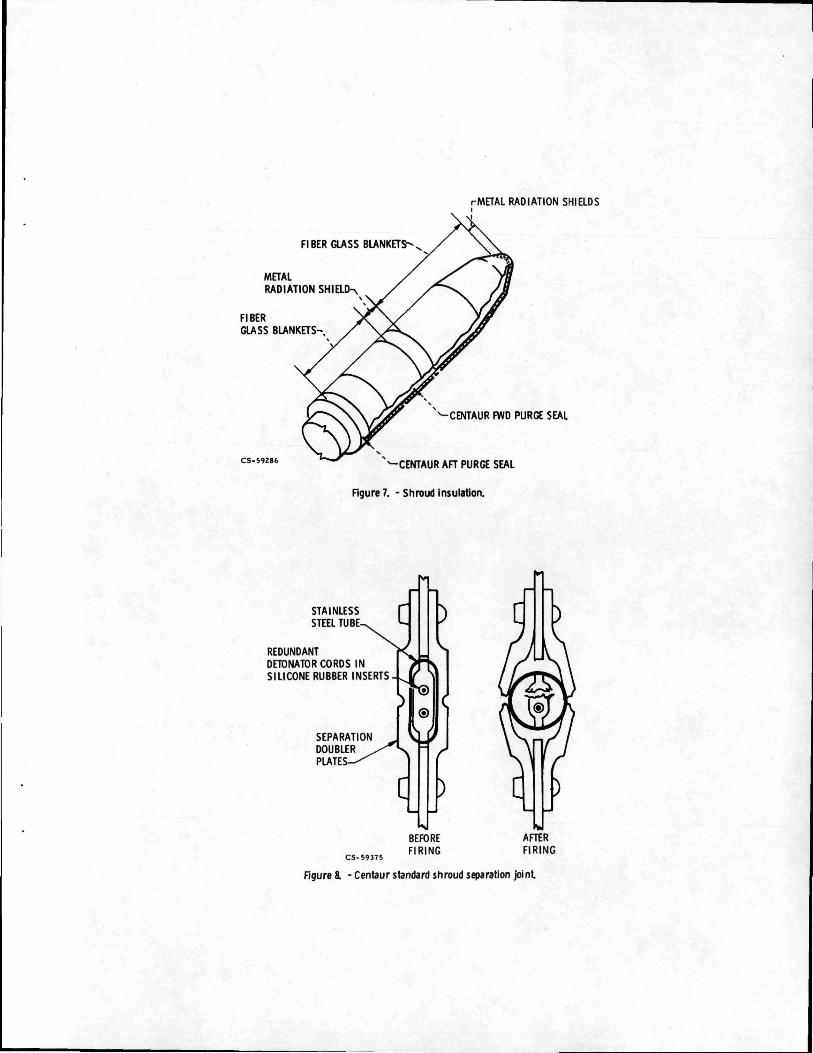
The shroud provides a protective shol) aroundthe Centaur and pay load and protects thorn from airloads and temperatures In excess of !>05 degreesKelvin C450 degrees Fahrenheit) as tho vehiclerises through the earth's atmosphere. Shroud in-sulation is as shown in Figure 7-
The shroud Is separated from the Titan/Centaurduring Titan Stage II flight. Jettison is accom-plished when an electrical command from the Centaurinitiates the separation system detonation. Redun-dant dual explosive cords are confined in a flat-tened steel tube which lies between two notchedplates around the circumference of the shroud nearthe base and up the sides of the shroud to the nosedome. The pressure produced by the explosive corddetonation expands the flattened tubes, breakingthe two notched plates and separating the shroudinto two halves (Figure 8) .
To ensure reliability, two completely redundantelectrical and explosive systems are used. If thefirst system should fail to function, the second isautomatically activated as a backup within one halfsecond.
Four base-mounted, coil-spring thrusters forceeach of the two severed shroud sections to pivotabout hinge poipts at the base of the shroud. Af-ter rotating approximately 60 degrees, each shroudhalf separates from its hinges and continues tofall back and away from the launch vehicle. Theentire separation sequence occurs in a period ofabout four seconds.
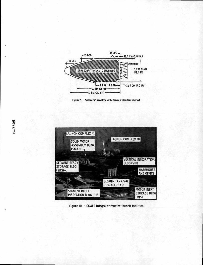
The Centaur Standard Shroud provides a large,environmentally protected volume for the space-craft. An envelope of the volume available to thespacecraft is illustrated in Figure 9.
The Centaur Standard Shroud is undergoing de-velopment and qualification testing at the NASA-Lewis Research Center's Plum Brook Station. Threeseries of tests are being run on the shroud todemonstrate its a b i l i t y to protect the Centaur andpayload during ground hold operations and duringascent- through the atmosphere. The first series oftests is complete and has verified that the shroudw i l l (1) thermally protect the Centaur when it istanked with cryogenic propellants and (2) unlatchor jettison from the Centaur under cryogenic con-ditions. The second series of tests w i l l verifythe structural design of the shroud. The thirdseries of tests w i l l prove that the shroud w i l ljettison successfully at simulated altitude afterit is subjected to heating that simulates theaerodynamic heating during ascent.
Launch Faci1ity
The Titan/Centaur vehicles w i l l be launchedfrom Complex k] at the Cape Kennedy Air Force Sta-tion under the direction of the NASA-John F. Ken-nedy Space Center's Unmanned Launch Operationsorganization. Launch Complex 41 is a part of theAir Force's East Coast Titan launch center, theIntegrate-Transfer-Launch (ITL) facility.
The ITL facility is shown in Figure 10. Itconsists of solid rocket motor servicing and stor-age areas; a Vertical Integration Building (VIB);
a Solid Motor Assembly Building (SMAB); Launch Com-plexes ^0 and 41, and a double-track locomotivesystem which transports tho mated Titan core andCentaur vehicle from the VIB through the SMAB toLaunch Complex 41.
The Titan, Centaur, and Centaur portion of theshroud are erected and mated in the VIB on a mobiletransporter/umbilical mast structure. Attached tothe transporter are three vans housing launch con-trol and monitoring equipment which remain connect-ed to the transporter and vehicle throughout thereceipt-to-launch sequence. Upon completion of in-tegrated tests in the VIB, the assembled Titan andCentaur are moved on the transporter to the SMAB.After the SRM's and core stages are structurallymated, the vehicle is moved to the launch complex.A mobile service structure provides access to allvehicle stages. An environmental enclosure pro-vides protection for the Centaur and the space-craft. The spacecraft prelaunch operations includecheckout and encapsulation in the payload sectionof the shroud and mating of the encapsulated space-craft to Centaur at the launch complex. The pro-cessing of the elements of the launch vehicle fromreceipt to launch is shown in Figure 11.
Modifications at the ITL to support the Titan/Centaur and spacecrafts included addition of Cen-taur propellant and gas services, expansion ofelectrical power and air conditioning, and additionof launch control monitoring equipment. Modifica-tions were made to handle and to give access to theTitan/Centaur vehicle and the spacecraft. The Com-puter Controlled Launch Set (CCLS), discussed pre-viously, is physically located at Launch Complex36. The CCLS supports both the Atlas/Centaur andTitan/Centaur programs.
Titan/Centaur Proof Flight
The first flight of the Titan/Centaur launchvehicle, scheduled for the first quarter of 1974,is a "Proof Flight" designed to demonstrate thecapability of the launch vehicle and its associatedground systems to support operational missions. Inaddition, a series of propellant management experi-ments w i l l be conducted to demonstrate the capabil-ity of the Centaur vehicle to coast for 5-1/4 hoursin a zero gravity environment, to support two-burnmissions with extended parking orbit coast phases,and to support three-burn synchronous orbit mis-s ions .
The payload w i l l consist of a mass model ofthe Viking spacecraft and a secondary spacecraftcalled the SPHINX (Space Plasma High Voltage In-teraction Experiment). The Viking mass model,which weighs approximately 3,545 kilograms (7,800pounds), is a dynamic representation of the Vikingspacecraft. The SPHINX spacecraft weighs approxi-mately 91 kilograms (200 pounds). The project ismanaged by NASA-Lewis Research Center and is de-signed to obtain scientific data. These data wi l lassist in establishing the design and test criteriaof high voltage systems for future spacecraft. TheProof Flight trajectory profile is shown in Figure12. The i n i t i a l phase of flight through the secondCentaur main engine cutoff w i l l simulate the Vikingtrajectory. The Centaur vehicle w i l l then be pro-grammed to coast in zero gravity in a relatively

low earth orbit for about 80 mlnutos. Followlny a.third Centaur burn, tho SPHINX spacecraft w i l l bo'separated. Tho Contour vehicle and tho mass modalw i l l continue to coast In zero gravity for about5-1A hours. The fourth Centaur burn w i l l occurnear synchronous altitude.
Titan/Centaur Performance Capability
As was noted previously, the Titan/Centaur wasadded to the NASA family of launch vehicles to f i l la performance gap between the Atlas/Centaur andSaturn V launch vehicles. The performance datapresented in Figure 13 for the Atlas/Centaur, Ti-tan/Centaur, and the Saturn V vehicles clearly il-lustrate that Titan/Centaur has accomplished thisgoal. Performance data are also presented for theTitan/Centaur vehicle with a spin-stabilized TE-16k-k solid rocket motor stage required for highenergy missions such as Jupiter fly-bys.
These data are based on the following groundrules:
1. Parking orbit ascent.
2. Launch azimuth - 90 degrees.
3. Parking orbit altitude - 167 kilometers(90 nautical miles).
k. Three sigma flight performance reserves.
5. Launch vehicle contingency - 68 kilograms(150 pounds) .
6. Payload capability includes separatedspacecraft, spacecraft adapter, and any other mis-sion peculiar equipment.
The representative Titan/Centaur payload cap-ability for specific missions includes:
1. Circular low earth orbit - 15,^22 kilograms(3̂ ,000 pounds)
2. Synchronous transfer
3. Planetary(C3 = 20 km
2/sec2)
*t. ./nchronous orbit(three-burn Centaur)
- 7,031 kilograms(15,500 pounds)
- 3,629 kilograms(8,000 pounds)
- 3,175 kilograms(7,000 pounds)
A Titan/Centaur ascent profile and majorflight event times are presented in Figure \k foran operational two-burn mission with a 30 minuteparking orbit coast phase.
A more detailed discussion on Titan/Centaurperformance capability is contained in Reference 2.
solar probos, Mars landers, Jupiter/Saturn fly-bys,Jupltor/Uranus fly-bys, dlroct flights to Saturn,and a Comot Encke fly-by.
References
1 . Driggers, G. W., "Short Guide to Titan IIILaunch Vehicles," Astronautics and Aeronautics,Volume II, No. 2. Feb. 1973, pp. 68-73.
2. Anon.: "Centaur Mission Planner's Guide,"Rev. A, Oct. 11, 1973, General Dynamics' Convair,San Diego, Calif.
Launch Schedule
The introduction of the Titan/Centaur launchvehicle in 197** w i l l usher in a new era of plane-tary and solar exploration. Figure 15 presentsthe current NASA planning for missions using theTitan/Centaur launch vehicle. The missions include
E-7505
CENTAUR -
TITAN STAGE 0SOLID MOTORS
CENTAURSTANDARDSHROUD
TITAN STAGE II
•TITAN STAGE I
EQUIPMENT MODULE
RADIATIONSHIELD
ATTITUDECONTROLENGINES —
HELIUMBOTTLE-
HYDROGENPEROXIDEBOTTLE -'
x-GUI DANCE, CONTROL.POWER. TELEMETRY,UMBILICAL PANEL,RANGE SAFETY
^-LIQUIDHYDROGENTANK
-INTERMEDIATEBULKHEAD
— LIQUIDOXYGENTANK
-»- MA IN ENGINES
Figure 2. - Improved Centaur.
Figure L -Titan/Centaur launch vehicle.

T_PULSE
RADIOCODE MODULATION
FREQUENCY SYSTEM
PULSE CODE MODULATIONTELEMETRY MULTIPLEXER
ATTITUDES,VELOCITY.& RATES
DIGITALDATA
STEERINGCOMMANDS
DISCRETES ENGINE
Figure 3. - Centaur astrionics block diagram.
STAGE II3L05MDIAM
25. 80 M (84 6 FT)
STAGE I
SOLID ROCKET MOTORS ' L°5 M DIAM r THRUST VECTORI (10 FT) \ CONTROL TANK
Figure 4 -Titan HIE booster.

COMPUTER
CENTAUR
SEQUENCECONTROL
UNIT
TITAN
GUIDANCE STEERING
DISCRETES
STAGINGTIMER
*
RELAYPACKAGES
DISCRETES
DISCRETES
3- AXISREFERENCE
SYSTEM
RATE-GYROSYSTEM
FLIGHTPROGRAMMER
A
FLIGHTPROGRAMMER
B
ATTITUDESIGNALS
PROGRAMMEDSTEERING
ATTITUDERATES
DISCRETES
DISCRETES
FLIGHTCONTROLSCOMPUTER
COMMANDS—- > STAGES
0, I. & II
Omr^
iW
DISCRETES TOORDNANCE, ENGINES, ETC
Figure 5. - Titan HIE flight control system.
1
Ar
PAYLOADcrrTIHMJLU 1 1 UIN
I
TANKSECTION
BOATTAI L TPTI AMbtt II UN
/
-u
\1l
\1lit-— LONGITUDINAL
*-jj!J SEPARATIONi_I'
);
j
!!jKI
JOINT
~--427MDIAM(14 FT)
17. 1 M <56
\17. 8 M (58. 5 FT)OVERALL LENGTH
FT)JETTI SON LENGTH
s
^CIRCUMFERENTIALcs.59291 SEPARATION JOINT
Figure 6. - Centaur standard shroud.
rMETAL RADIATION SHIELDS
FIBER GLASS BLANKETS-
CS-59286
METAL
RADIATION SHIELCK
FIBER
GLASS BLANKETS-.
CENTAUR FWD PURGE SEAL
^-CENTAUR AFT PURGE SEAL
Figure 7. - Shroud insulation.
STAINLESSSTEEL TUB
REDUNDANTDETONATOR CORDS INSILICONS RUBBER INSERTS
SEPARATIONDOUBLERPLATE:
>sBEFOREFIRING
AFTERFIRING
Figure & - Centaur standard shroud separation joint
SPACECRAFT DYNAMIC ENVELOPE 3L7MDIAMj (12.1 FT)
12.7 CM (5.0 IN.)
Figure 9. - Spacecraft envelope with Centaur standard shroud.
inomr-i
W LAUNCH COMPLEX 41
LAUNCH COMPLEX 40SOLID MOTORASSEMBLY BLDG(SMAB)
VERTICAL INTEGRATIONBLDG(VIB)SEGMENT READY
STORAGE BLDGWAREHOUSEAND OFFICE
SEGMENT ARRIVALSTORAGE(SAS)
• SEGMENT RECEIPTINSPECTION BLDG(RIS)
MOTOR INERTSTORAGE BLDG(MIS)
Rgure 10. - CKAFS integrate-transfer-launch facilities.

CENTAUR
TITAN CORE
atCLT
A
A
m
AIA
SOLID MOTORS & t"™^ *W&css,505 (VERTICAL (SOLIDMOTOR COMPLEX 41
INTEGRATION ASSY BLDG)BLDG)
Figure 1L - Prelaunch hardware assembly at the integrate-transfer-launchfacility.
•a, CENTAUR BURN COAST
PARKING 1ST 135 SEC 12MINORBIT 2ND MSEC 80MIN
3RD 185 SEC 5.25 HR4TH 70 SEC
I INTERMEDIATE ORBIT-
«.»«7 TERMINAL ORBIT
TRANSFERORBIT
ALTITUDE • 357 436 KM19 300 N Ml
Figure 12. - Titan/Centaur proof flight trajectory.

inoinr~i
W
1000008000080 000
40000
20000
>r 10000
r; 8000ea2 6000
3 4000
2000
1000
800
600
400
SATURN V
10 12 14 16CHARACTERISTIC VELOCITY, KM/SEC
Figure 11 -Titan/Centaur performance capability.
18

TITAN/CENTAURSEPARATION ftCENTAUR PRESTARTEVENTS
COAST. ORIENTSPACECRAFT.• SEPARATE
MEC02
TITAN SECOND STAGE ENGINESHUTDOWN ft RETRO FIRE
TITAN FIRST STAGE ENGINE SHUTDOWNft SECOND STAGE ENGINE START
TITAN FIRST STAGE ENGINE STARTft ZERO STAGE SEPARATION
START SOLID ROCKET MOTORS
CENTAURRETROMANEUVERft PROKLIAMT
SMCECRAFTCONTINUES
ENDCENTAURMISSION
EVENT
LIFTOFF ISRMs FIRING. STAGED)
CORE STAGE I IGNITION
JETTISONSRMs
STAGE I SHUTDOWN
CORE STAGE 11 IGNITION
SEPARATE STAGE I AND STAGE II
JETTISON SHROUD
STAGE II SHUTDOWN
SEPARATE TITAN AND CENTAUR
CENTAUR MAIN ENGINE START. MES 1
CENTAUR MAIN ENGINE CUTOFF, MECO 1
CENTAUR MAIN ENGINE START, MES 2
CENTAUR MAIN ENGINE CUTOFF. MECO 2
SPACECRAFT SEPARATION
APPROXIMATE TIME
FROM LIFTOFF.
SEC
D
111
122
258
258
KH
270
467
473
433
613
2413
2725
2956
figure 14 - Typical Titan/Centaur flight profile for a two-burn mission.

mo
W
MISSION
PROOF FLIGHT
*HELIOS (SOLAR PROBE)
VIKING (MARS LANDER)
MARINER 77 (JUPITER/SAT)
MARINER 79 (JUPITER/URANUS)
*PIONEER SATURN
«COMET ENCKE FLYBY
1974
V
T
1975
W
1976
V
1977
*T
1978 1979
V
W
V
1980
V
'REQUIRES SPIN-STABILIZEDTE-364-4 STAGE
T APPROVEDV PROPOSED
Figure 15. - Titan/Centaur launch schedule.
NASA-Lewis