ha 35z-1 ha 2 3.5 mpa small-bore hydraulic cylinder 3 · pdf file ·...
TRANSCRIPT

3.5 MPa Small-bore Hydraulic Cylinder35Z-135Z-1 General Hydraulic Cylinders
2HA
3.5 MPa Small-bore Hydraulic Cylinder 35Z-1General H
ydraulic Cylinders
35Z-1
3HA
Small-bore hydraulic cylinders
Note) Slipper Seal is the registered trade mark of Nippon Valqua Industries, Ltd.
Standard SpecificationsNominal pressurePressure given to a cylinder for convenience of naming.It is not always the same as the working pressure (rated pressure) that guarantees performance under the specified conditions.
Maximum allowable pressureMaximum allowable pressure generated in a cylinder (surge pressure, etc.)
Proof test pressureTest pressure against which a cylinder can withstand without unreliable performance at the return to nominal pressure.
Notes) ●The hydraulic pressure generated in a cylinder due to the inertia of load must be lower than the maximum allowable pressure.●For the internal structure, refer to the sectional drawings at the end of this catalog.
Terminologies
Standard Stroke Range Unit: mm
●The above strokes indicate the maximum available strokes for the standard type.●For the rod buckling, check with the buckling chart in the selection materials. Contact us for longer strokes.
Adaptability of Fluid to Seal Material
Sensor Mountable Minimum Stroke Unit: mm
3.5 MPa
4 MPa
5 MPa
0.1 to 300 mm/s
- 10 to + 70℃
(No freezing)
None
Petroleum-based fluid
(When using another fluid, refer to the table of fluid adaptability.)
JIS 6g/6H
0 to 250 mm 251 to 600 mm
SD, LB, FA, FB, CA, CB with pin
Rod eye (S-end), rod clevis (Y-end), floating joint (F-end)
CB bracket
Type Standard type Switch Set
Nominal pressure
Maximum allowable pressure
Proof test pressure
Working speed range
Working temperature range
(ambient/fluid temperature)
Structure of cushioning
Adaptable fluid
Tolerance for thread
Tolerance of stroke
Mounting style
Accessories
Rod end attachments
Others
+1.0 0
+1.4 0
Seal material
Nitrile rubber
Adaptable fluid
Petroleum-based fluid
Phosphate ester fluid
Water in oil fluid
Oil in water fluid
× ○ ○ ○
Water-glycol fluid
○
Bore
Typef20 f25 f32
Standard type
Switch Set
400
400
500
500
600
600
BoreWith one sensor
AX/AZ type SR type AX/AZ type SR type
With two sensors
f20
f25
f32
10 20
●Tie rod type small-bore hydraulic cylinders.●Slipper seal is used as the piston seal.●Copper alloy bushing, and wear ring fitted to piston.●Reed sensors or solid state sensors can be selected.Solid state sensors which can be easily set in the optimum positions through visual check are available.
Product Lineup
General purpose type
Double acting single rod
Unit: mm
Standard type35Z-1
Switch Set35Z-1R
Series Variation Type f20 f25 f32
Notes)●When using a sensor, use a Switch Set Cylinder.●No sensor can be mounted onto the standard type cylinder.
Double acting single rod
Standard type(35Z-1) Switch Set(35Z-1R)
Weight Table Unit: kg
Sensor Additional Weight Unit: kg
Bore
mm
Basic weight
Basic style35Z-1
Switch Set35Z-1R
f20
f25
f32
0.390
0.473
0.632
0.395
0.480
0.638
0.00223
0.00265
0.00316
0.135
0.150
0.200
0.130
0.145
0.155
0.105
0.120
0.180
0.105
0.125
0.165
0.350
0.350
0.465
0.075
0.075
0.110
0.10
0.10
0.17
0.11
0.11
0.19
Mounting accessory weight Rod end attachment weight
LB styleCB style
with pin/split pinCB style
with bracketRod eye(S-end)CA style
Rod clevis(Y-end)with pin
FA styleFB style
Floating joint(F-end)
Additional weight per
mm of stroke
Sensor
Bore mm
AX/AZ type
Cord length 1.5 m Cord length 5 mWith connectorCord length 5 m
SR type
f20
f25
f32
0.05 0.04 0.22 0.13
Calculation formula Cylinder weight (kg)=basic weight+(cylinder stroke (mm)×additional weight per mm of stroke)+(sensor additional weight×sensor quantity)+mounting accessory weight+rod end attachment weight35Z-1R, bore φ32, cylinder stroke 300 mm, 2 pcs of AX101 (cord length 1.5 m), LB style, rod eye (S-end)0.638+(300×0.00316)+(0.05×2)+0.200+0.110=1.996kg
Calculation example

3.5 MPa Small-bore Hydraulic Cylinder35Z-135Z-1 General Hydraulic Cylinders
4HA
3.5 MPa Small-bore Hydraulic Cylinder 35Z-1General H
ydraulic Cylinders
35Z-1
5HA
35Z-1 1 LB 20 N 100 - C 2 -
35Z-1R 1 LB 20 N 100 - AH 2 -
General Purpose Type
●Standard type
Mounting style
●Switch Set
Nitrile rubber
Bore (mm)f20・f25・f32
No cushion
Cylinder stroke (mm)
Rod eye with spherical bearing (S-end)Rod clevis (Y-end)Floating joint (F-end)
Sensor quantity (1, 2, to n)
Sensor symbolNote) Select applicable sensors out of the
Sensor List.
●! Notes on ordering Switch Set●When no sensor is required, specify 0 for the sensor symbol ❼ and the sensor quantity ❽.●Sensors are not mounted on cylinders at delivery.
Bracket can be fitted.Mounting style: CB
Standard Stroke Range
Sensor Mountable Minimum Stroke
Adaptability of Fluid to Seal Material
Standard specifications
●No cushion on both ends●Port position Ⓐ
Change of port positionThe standard port position is Ⓐ. When modifying the positions, enter the symbol shown in the dimensional drawings.
Port position (A, B, C, D)Example) 35Z-1R 1LB20N100 - B 0 AH 2
No cushion
Note) ○: Applicable ×: Inapplicable
A
C
D B
End Lock Nut Part Number
S
S
B
B
The item enclosed by broken line needs not to be entered, if unnecessary.
f20 f25 f32
Bore Part number
f20
f25
f32
LNA-10B-H
LNA-12B-H
f20
f25
f32
10 20
Type❶
Seal material❷
Mounting style❸
Cylinder bore❹
Cushioning❺
Stroke❻
Sensor symbol❼
Sensor quantity❽
Rod end attachment❾
Bracket10
× ○ ○ ○ ○
Unit: mm
●The above strokes indicate the maximum available strokes for the standard type.●For the rod buckling, check with the buckling chart in the selection materials. Contact us for longer strokes.
Bore
Type
Standard type
Switch Set
400
400
500
500
600
600
Unit: mm
BoreWith one sensor
AX/AZ type SR type AX/AZ type SR type
With two sensors
Seal material
Nitrile rubber
Adaptable fluid
Petroleum-based fluid
Phosphate ester fluid
Water in oil fluid
Oil in water fluid
Water-glycol fluid
Sensor List
Notes) ●For the sensors without a protective circuit, be sure to provide a protective circuit (SK-100) with the load when using any induction load (relay, etc.).●The output logic of AX135CE is B contact. When the piston is detected, the sensor contact turns off (the lamp turns on).●For handling of sensors, be sure to see the sensor specifications at the end of this catalog.●We recommend AND Unit (AU series) for multiple sensors connected in series.For details, refer to AND Unit at the end of this catalog.
Mounting Style
SD style (basic style)SD
LB style (end angles)LB FB style (cap flange)FB
CA style (cap eye)CAFA style (rod flange)FA
CB style (cap clevis) (with pin)CB
■Semi-standard
SR type sensorAX type sensor
Cord type Connector type
None
AF AX101CE
AG AX105CE
AH AX111CE
A J AX115CE
AE AX125CE
AK AX11ACE
A L AX11BCE
AM AX135CE
S SR405
BE AX201CE-1
BF AX205CE-1
CE AX211CE-1
CF AX215CE-1
CT AX211CE-1
CU AX215CE-1
CV AX21BCE-1
CW AZ211CE-1
CX AZ215CE-1
CY AZ21BCE-1
Type Cord length Applicable load
Small relay, programmable controller
Small relay, programmable controller
Sensor symbol Wiring methodIndicating lampLoad current rangeLoad voltage range Protective circuit
None
Provided
Provided
Provided
Provided
None
Provided
Max. switching capacity
1.5 m
5 m
1.5 m
5 m
1.5 m
5 m
0.5 m
1.5 m
5 m
0.5 m
1.5 m
5 m
1.5 m
5 m
5 m
0.5 m
0.5 m
5 m
5 m
Ree
d se
nsor
Sol
id s
tate
sen
sor
0.3 mm², 2-core, outer dia. f4 mm, rear wiring
0.3 mm², 2-core, outer dia. f4 mm, rear wiring
4-pin connector type, rear wiring
4-pin connector type, rear wiring
4-pin connectortype, upper wiring
0.5 mm², 2-core, outer dia. f6 mm, rear wiring
0.3 mm², 2-core, outer dia. f4 mm, rear wiring
0.3 mm², 2-core, outer dia. f4 mm, rear wiring
0.3 mm², 2-core, outer dia. f4 mm, upper wiring
LED(Lights in red
when sensing)
LED (Lights in redwhen sensing)
Neon lamp (Lightswhen not sensing)
LED (Lights in redwhen sensing)
LED (two-LEDtype in red/green)
DC: 1.5 W AC: 2 VA
30 VA
2 VA
1.5 W
5 to 20 mA
5 to 40 mA
DC: 5 to 40 mA AC: 5 to 20 mA
2 to 300 mA
― 5 to 40 mA
LED (two-LEDtype in red/green)
DC: 5 to 30 V
AC: 5 to 120 V
DC: 5 to 30 V
B contact output5 to 300 mAAC/DC: 90 to 240 V
DC: 5 to 30 V AC: 5 to 120 V
AC: 80 to 220 V
DC: 30 V or lessAC: 120 V or less
DC: 40 mA or lessAD: 20 mA or less
LED (Lights in redwhen not sensing)
●How to order
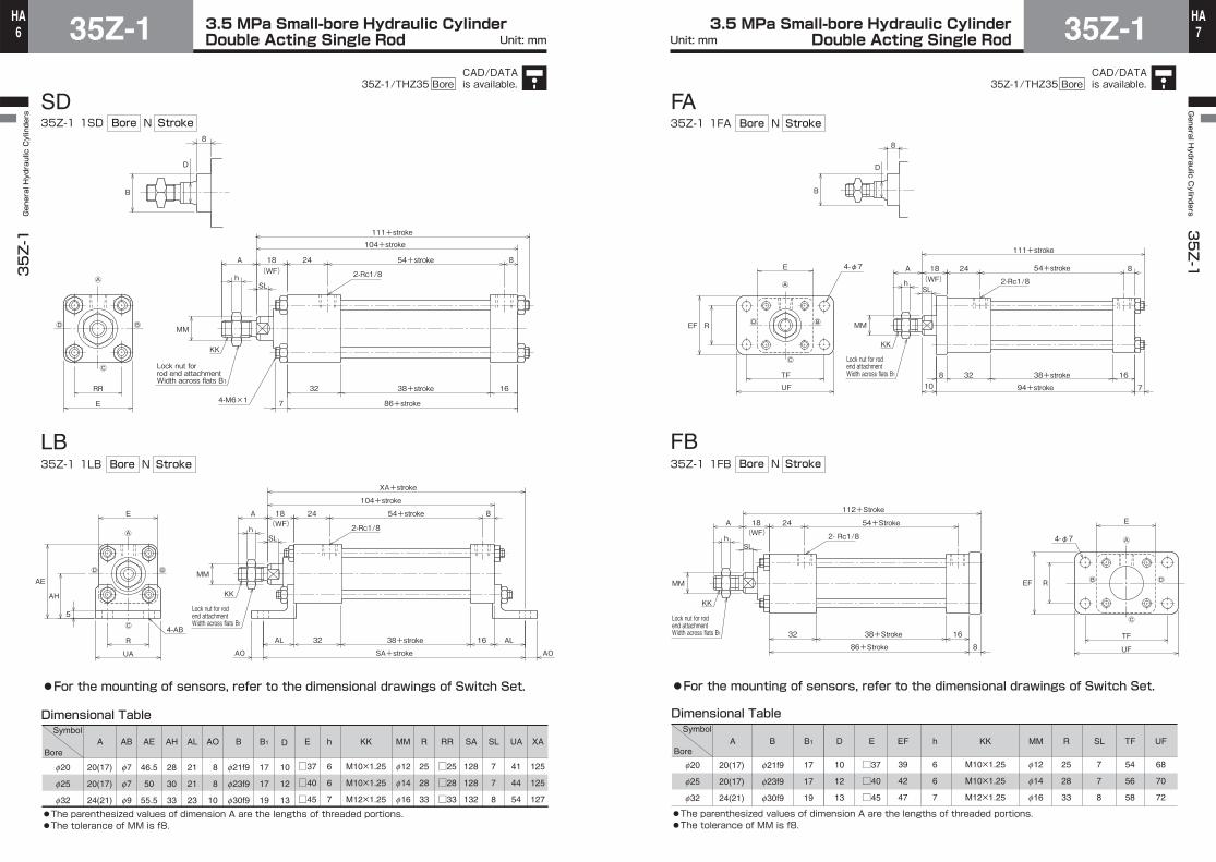
3.5 MPa Small-bore Hydraulic CylinderDouble Acting Single Rod35Z-1
35Z-1 General Hydraulic Cylinders
6HA 3.5 MPa Small-bore Hydraulic Cylinder
Double Acting Single Rod 35Z-1General H
ydraulic Cylinders
35Z-1
7HA
Unit: mm Unit: mm
SDN
LB
35Z-1 1SD StrokeBore
35Z-1 1LB
●For the mounting of sensors, refer to the dimensional drawings of Switch Set.
Dimensional Table
2-Rc1/8
RR
MM
E
54+stroke 82418(WF)
104+stroke111+stroke
A
32 38+stroke 16
86+stroke7
h
B
D
8
Ⓐ
Ⓒ
ⒷⒹ
Lock nut for rod end attachmentWidth across flats B1
4-M6×1
KK
SL
4-AB
2-Rc1/8
R
MM
UA
E
5
AH
AE
54+stroke2418 8(WF)
A
AL 32 38+stroke
AO
AL16
AOSA+stroke
104+stroke
XA+stroke
hⒶ
Ⓒ
Lock nut for rod end attachmentWidth across flats B1
KK
SL
ⒷⒹ
10
12
13
Symbol
Bore
f20
f25
f32
A AB
20(17)
20(17)
24(21)
f7
f7
f9
AE
46.5
50
55.5
AH
28
30
33
AL
21
21
23
8
8
10
AO B
f21f9
f23f9
f30f9
B1
17
17
19
M10×1.25
M10×1.25
M12×1.25
KK
f12
f14
f16
MM
25
28
33
R
□25
□28
□33
RR
128
128
132
SA
7
7
8
SL
41
44
54
UA
125
125
127
XA
6
6
7
h
□37
□40
□45
ED
●The parenthesized values of dimension A are the lengths of threaded portions.●The tolerance of MM is f8.
N StrokeBore
B1BA
f21f9
f23f9
f30f9
20(17)
20(17)
24(21)
f20
f25
f32
17
17
19
D
10
12
13
E
□37
□40
□45
EF
39
42
47
h
6
6
7
KK
M10×1.25
M10×1.25
M12×1.25
MM
f12
f14
f16
R
25
28
33
SL
7
7
8
TF
54
56
58
UF
68
70
72
FA
FB
35Z-1 1FA
35Z-1 1FB
Dimensional Table
4-φ7
MM
2-Rc1/8
TF
EF R
UF
E 54+stroke24 818(WF)
111+stroke
A
8 32 38+stroke 16
94+stroke 7
h
10
B
D
8
Ⓐ
Ⓒ
ⒷⒹ
Lock nut for rod end attachmentWidth across flats B1
KK
SL
2- Rc1/8 4-φ7
54+Stroke2418(WF)
A
38+Stroke32 16
86+Stroke 8
112+Stroke
h
E
REF
TF
UF
MM
Ⓐ
Ⓒ
Ⓑ Ⓓ
Lock nut for rod end attachmentWidth across flats B1
KK
SL
N StrokeBore
N StrokeBore
●For the mounting of sensors, refer to the dimensional drawings of Switch Set.
●The parenthesized values of dimension A are the lengths of threaded portions.●The tolerance of MM is f8.
Symbol
Bore
CAD/DATAis available.35Z-1/THZ35 Bore
CAD/DATAis available.35Z-1/THZ35 Bore

3.5 MPa Small-bore Hydraulic CylinderDouble Acting Single Rod35Z-1
35Z-1 General Hydraulic Cylinders
8HA 3.5 MPa Small-bore Hydraulic Cylinder
Double Acting Single Rod 35Z-1General H
ydraulic Cylinders
35Z-1
9HA
Unit: mm Unit: mm
f20
f25
f32
20(17)
20(17)
24(21)
f21f9
f23f9
f30f9
B
17
17
19
B1
f10
f10
f12
Notes) CD
36
36
46
CP
10
12
13
D
6
6
7
h
f12
f14
f16
MM
R12
R12
R14
MR1
R12
R12
R15
MR2
7
7
8
SL
24
24
32
UB
127
127
129
XC1
122
122
123
XC2
137
137
141
ZC1
132
132
136
ZC2
M10×1.25
M10×1.25
M12×1.25
KK
R14
R14
R16
LR1
R16
R16
R18
LR2
□37
□40
□45
E
12
12
16
EW1
12
12
16
EW2
H9f8
H9f8
H9f8
0-0.058
0-0.058
0-0.070
+0.7+0.5
+0.7+0.5
+0.7+0.5
Notes)
CA
CB
35Z-1 1CA
35Z-1 1CB
Dimensional Table
A
2-Rc1/8
54+Stroke2418 8(WF)
A
38+Stroke 81632
hSL
XC1+Stroke
ZC1+Stroke
EW1
E
MM
B
D
8
Lock nut for rod end attachmentWidth across flats B1
KK
CD
LR1
MR1
CD
LR2
MR2
2-Rc1/8(WF)
Lock nut for rod end attachmentWidth across flats B1
KK
54+Stroke2418 8A
38+Stroke
h
81632
XC2+Stroke
ZC2+Stroke E
EW2
UB
CP
MM
SL
N StrokeBore
N StrokeBore
●For the mounting of sensors, refer to the dimensional drawings of Switch Set.
Symbol
Bore
●f8 is the pin size.●The parenthesized values of dimension A are the lengths of threaded portions.●The tolerance of MM is f8.
Switch SetN35Z-1R 1 StrokeBoreSD – Sensor symbol Sensor quantity
●AX1**, AZ1**(reed sensor)・AX2**, AZ2**(solid state sensor)
●SR type (reed sensor)
Dimensional Table
Operating Range and Hysteresis
Type
BoreSymbol
AX/AZ type SR type
Boremm
Reed sensor Solid state sensor
AX1**・AZ1** SR type AX2**・AZ2**
Operating range Hysteresis Operating range HysteresisOperating range Hysteresis
5 to 10 2 or less3 to 71 or less
f20
f25
f32
7 to 10 2 or less
6 to 10 3 or less
UX UX30 7 SensorRY Max. 3RY
RV
Indicating lamp
RYMax. 3
RYRV
UX UX40 4Sensor
Indicating lamp
RY UX RV RY UX
68
72
78
34
36
39
4
4
5
9
9
9
29
30.5
33
RV
58
61
66
f20
f25
f32
Note) Dimension UX indicates the optimum sensor mounting position for detection of stroke end.
CAD/DATAis available.35Z-1/THZ35 Bore
CAD/DATAis available.35Z-1/THZ35 Bore

3.5 MPa Small-bore Hydraulic CylinderDouble Acting Single Rod35Z-1
35Z-1 General Hydraulic Cylinders
10HA
35Z-1General H
ydraulic Cylinders
35Z-1
11HA
3.5 MPa Small-bore Hydraulic CylinderUnit: mm Unit: mm
●Rod clevis (Y-end) with pin
●Rod eye with spherical bearing (S-end)
PL
CF
CT
PF
CB
CC
CNCL CA
CD
KK
Split pinWasher
W
Dimensional Table
Dimensional TableSymbol
BorePart number
f20
f25
f32
RSA-10-H
RSA-12-H
CA
50
43
CD
f12H9
f10H9
CF
f22
f19
CM
15
13
CN
65
56
DK ED
f15.4
f12.9
GW
30
26
16
14
KK
M12×1.25
M10×1.25
TA
24
21
TV
12±0.1
10.5±0.1
TW
19
17 0 -0.1
0 -0.1
f20
f25
f32
RYA-10-H
RYA-12-H
CA
40
48
CB CC
20
24
CD CF
f18
f20
CL
12
14
CN
52
62
CT
□20
□24
KK
M10×1.25
M12×1.25
PF
2.5
3
PL
30
36.5
W
20
24
H8 f8
H8 f8
+0.4 +0.1
+0.4 +0.1
10
12
f10
f12
Lubricating port
CD
DK
ED CF
TACN
CM CA
GW TW
KK
TV
4°
Symbol
BorePart number
●Floating joint (F-end)
●Bracket for CB style
●f20・f25 ●f32
●The insertion of the floating joint into the socket shall not equal or exceed the dimension of screw diameter. (Return the joint one or two turns after it gets into contact with the socket bottom, and fix it with a lock nut.) Excessive insertion can cause operation failure.●DO NOT use together with CA and CB accessories.
Notes)
Dimensional Table
Dimensional Table
Symbol
Bore
f20
f25
f32
Part number
RFH-10
RFH-12
30
FC
36.5
17
B1
19
20.5
A
24
29
FA
33
4
FD
11
59
FJ
69.5
11
FK
13.5
24
FN
19
6
h
7
M10×1.25
KK
M12×1.25
4.5
FQ
7
FR
f25
FM
f32
1
e
1
10
B2
13
18
20.5
BCA-10-H
BCA-12-H
f20
f25
f32
58
65
XM
76
85
WM
f7
f9
LB
50
56.5
KG
55
63
KC
7
8
BT
10
11.5
BO
9
10
BL
30
35
BH
35
40
BF
e
e
KK
Lock nutWidth across flats B1
Width across flats B2
KK
hFRA FQ
FA FC
FD
FJ
FK
5°
5°
Eccentricity FM FN
Rotating angle
Lock nutWidth across flats B1
Width across flats B2
FM
h
FRA FQ FD
FAFJ
FC
FK
FN
e
e
5°
5°
Eccentricity
Rotating angle
KK
KK
4-LB
KG5
BracketPin
KCBFBO BO
WMXM
BH
BTBL BL
Symbol
BorePart number
CAD/DATAis available.35Z-1/THZ35 Bore
CAD/DATAis available.35Z-1/THZ35 Bore
3.5 MPa Small-bore Hydraulic Cylinder35Z-135Z-1 General Hydraulic Cylinders
12HA
General H
ydraulic Cylinders
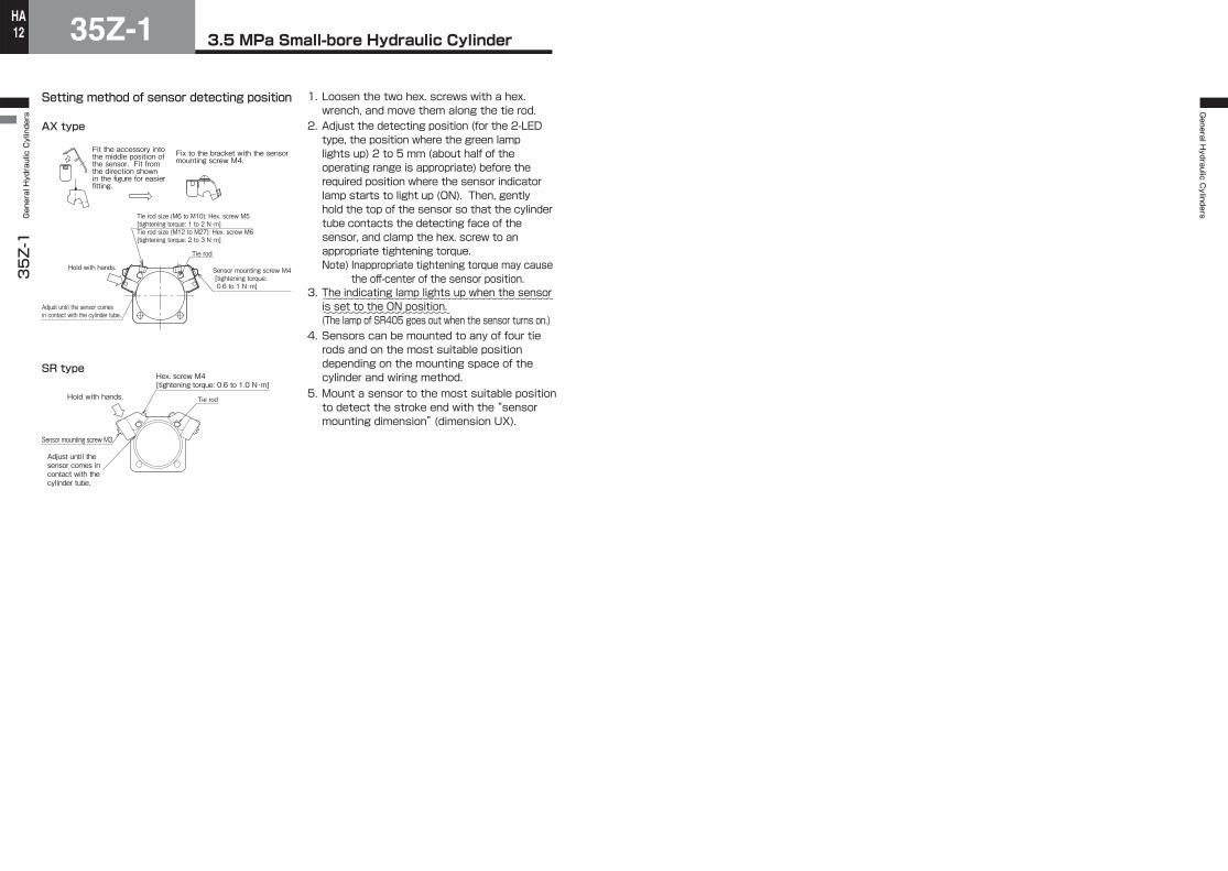
Setting method of sensor detecting position
SR type
1. Loosen the two hex. screws with a hex. wrench, and move them along the tie rod.
2. Adjust the detecting position (for the 2-LED type, the position where the green lamp lights up) 2 to 5 mm (about half of the operating range is appropriate) before the required position where the sensor indicator lamp starts to light up (ON). Then, gently hold the top of the sensor so that the cylinder tube contacts the detecting face of the sensor, and clamp the hex. screw to an appropriate tightening torque.Note) Inappropriate tightening torque may cause
the off-center of the sensor position.3. The indicating lamp lights up when the sensor is set to the ON position.(The lamp of SR405 goes out when the sensor turns on.)
4. Sensors can be mounted to any of four tie rods and on the most suitable position depending on the mounting space of the cylinder and wiring method.
5. Mount a sensor to the most suitable position to detect the stroke end with the “sensor mounting dimension” (dimension UX).
~~~~~~~~~~~~~~~~~~~~~~~~~~~~~~~~~~~~~~~~
~~~~~~~~~~~~~~~~~~~~~~
AX type
Fit the accessory into the middle position of the sensor. Fit from the direction shown in the figure for easier fitting.
Fix to the bracket with the sensor mounting screw M4.
Adjust until the sensor comes in contact with the cylinder tube.
Hold with hands.
Tie rod size (M6 to M10): Hex. screw M5 [tightening torque: 1 to 2 N・m]Tie rod size (M12 to M27): Hex. screw M6 [tightening torque: 2 to 3 N・m]
Tie rod
Sensor mounting screw M4 [tightening torque: 0.6 to 1 N・m]
Tie rod
Adjust until the sensor comes in contact with the cylinder tube.
Sensor mounting screw M3
Hold with hands.
Hex. screw M4 [tightening torque: 0.6 to 1.0 N・m]