hand pumps - dana brevini fluid power · brevini fluid power was established in 2003 in reggio...
TRANSCRIPT
Technical Catalogue
HAND PUMPS
April
2016
web edition
The companyBrevini Fluid Power was established in 2003 in Reggio Emilia where it has its head office.Brevini Fluid Power manufactures hydraulic components and application packages: a very large range suited to several operational requirements and applications thanks to a strict interaction between mechanical, hydraulic and electronic components.Brevini Fluid Power is among the top manufacturers in Italy and a major player in Europe and in the world.
International presenceBrevini Fluid Power operates internationally with 15 branches all over the world placed in major industrialized countries: Italy, France, Germany, English, Romania, Holland, Finland, China, India, Singapore and the United States. The network is constantly expanding by opening new branches in just a few years.The branches are guided by managers that have an excellent knowledge of their own country. The advantages this brings are evident:
The production facilities are located throughout Reggio Emilia, Ozzano Emilia (BO), Noceto (PR), Novellara (RE), Yancheng (province of Jiangsu, China) which was inaugurated in 2009 and became operative since 2010.
Competitive StrategyInnovation combined with the focus on customers is the strength of the Brevini Fluid Power “brand”, born from the forty-year-long
Brevini Fluid Power proposes itself as a “local hub”, as it happened to BPE Electronics in 2008 and OT Oiltechnology in 2009, in order
The purpose is still the development of a very large range of products forming together integrated packages able to meet various ap-plication needs. Our ten-year-long partnership relations with hundreds of customers all over the world are the best synthesis of Brevini
Sharing of know-how and several experiences have made Brevini Fluid Power a more global company, more incisive in international markets and closer to its customers.
Product lines The product lines are numerous and well-structured aimed to cover every needs: a strong basis on which to develop the engineering of application packages and complete systems. The offer is improving in the direction of a solution supplier often developed in co-design with the customer, both for the mobile and industrial sector.
Hydr-App Product Line: Hydraulic power packs and mini hydraulic packs (whether standard or customised), cartridge valves and solenoid valves, gear boxes and transmission components.S.A.M. Hydraulik Product LineAron Product Lineblocks.Brevini Hydraulics Product Line: Proportional directional valves, joysticks and electronic modules.BPE Electronics Product LineVPS Brevini Product LineOT Oiltechnology Product Line

1IE/HP_INTRO/00-2015
Hand pumps
© 2015 Brevini Fluid Power S.p.A. All rights reserved. Hydr-App, SAM Hydraulik, Aron, Brevini Hydraulics, BPE Electronics, VPS Brevini, OT Oiltechnology, logos are trademarks or are registered trademarks of Brevini Fluid Power S.p.A. or other companies of the Brevini Group in Italy and other countries.
The technical features supplied in this catalogue are non binding and no legal action can be taken against such material. Brevini Fluid Power will not be held responsible for information and specifications which may lead to error or incorrect interpretations. Given the continuous technical research aimed at improved technical features of our products, Brevini Fluid Power reserves the right to make change that are considered appropriate without any prior notice. This catalo-gue cannot be reproduced (in while or in part) without the prior written consent of Brevini Fluid Power. This catalogue supersedes all previous ones.
Use of the products in this catalogue must comply with the operating limits given in the technical specifications. The type of application and operating condi-tions must be assessed as normal or in malfunction in order to avoid endangering the safety of people and/or items.
General terms and conditions of sale: see website www.brevinifluidpower.com.
The products shown on this catalog are parts of line.
Table of contentsHow to order ..................................................................................................... 2Technical information ..................................................................................... 3
HAND PUMPS FOR FIXING TO TANK Double acting PM 06/12/25/45 S** 00 2 ........................................................................ 5 PM 06/12/25/45 S** 02 2 ........................................................................ 6 PM 06/12/25/45 S** 03 2 ........................................................................ 7 PM 06/12/25/45 S** 14 2 ........................................................................ 8 PM 06/12/25/45 S** 11 2 ........................................................................ 9 PM 06/12/25/45 S** 12 2 ...................................................................... 10 Double acting and flow divider PMI 06/12/25/45 S** 04 2 ..................................................................... 11 PMI 06/12/25/45 S** 05 2 ..................................................................... 12 PMI 06/12/25/45 S** 00 2 ..................................................................... 13 PMI 06/12/25/45 S** 06 2 ..................................................................... 14 Double acting, flow divider and dual pilot check valve PMB 06/12/25/45 S** 00 2 .................................................................... 15 PMB 06/12/25/45 S** 07 2 .................................................................... 16 PMB 06/12/25/45 S** 08 2 .................................................................... 17 PMB 06/12/25/45 S** 09 2 .................................................................... 18 Single acting 1PMS 20/30/40 S** 00 2 ....................................................................... 19 1PMS 20/30/40 S** 02 2 ....................................................................... 20 1PMS 20/30/40 S** 03 2 ....................................................................... 21 Horizontal 2PMS 08/15 S** 00 2 ............................................................................. 22 2PMS 08/15 S** 02 2 ............................................................................. 23 2PMS 08/15 S** 03 2 ............................................................................. 24
Steel oil tanks ................................................................................................ 25
HAND PUMPS FOR FIXING TO WALL PM 020 00 2 ............................................................................................ 26 PM 020 03 2 ............................................................................................ 27 PM 020 10 2 ............................................................................................ 28 PM 050 00 2 ............................................................................................ 29 PM 050 03 2 ............................................................................................ 30 PM 050 10 2 ............................................................................................ 31
Lever for hand pumps .................................................................................... 32
SPECIAL PUMPSPMP 12 0003 ..................................................................................................... 33
INFOPUMPS INDEX

2IE/HP_INTRO/00-2015
PM 06 S00 no 00 2PMI 12 S01 1 lt. 01PMB 25 S02 2 lt. 02
45 S03 3 lt. 03S05 5 lt. ..
20 S07 7 lt.
1PMS 30 S10 10 lt.
40
2PMS 0815
PM 020 00 2050 01
..
How to order
Hand pump for fixing to tank (without lever*) Hand pump for fixing to wall (without lever*)
* The lever has to be ordered separately, see page 32
lever
release hand knob
HAND PUMP
tank
lever
release hand knob
HAND PUMP
VariantsType Displacementcm³ Serie
TankLiter
Fxin
g to
tank
Fixi
ng to
wal
l
INFOPUMPS INDEX
3
min. max.
ISO VG 10 10 9.00 11.0
ISO VG 15 15 13.5 16.5
ISO VG 22 22 19.8 24.2
ISO VG 32 32 28.8 35.2
ISO VG 46 46 41.4 50.6
ISO VG 68 68 61.2 74.8
ISO VG 100 100 90.0 110
15000
600
4000400
2000
5000
200
1000
1500
100
400
500
40
200
300
20
50
1505 30
50
SSU °E mm²/s
310
20000500
5000
10000 300 3000
2000
150
1500
1000
50
500
400
30
300
200
10
100
100
4
40
2
20
0 1 0
mm²/s°E
°C
°F
ISO
VG
100
ISO
VG
68
ISO
VG
32
ISO
VG
22
ISO
VG
46
-20
2.80
3
3.5
4
4.5
5
6
7
8
9
10
12
11
13
15
17
20
25
30
40
50
60
70
100
150
200
300
400
600
800
1000
1500
2000
3000
5000
7000
10000
2000
1000
500
300
200
100
70
40
20
10
8
6
4
3
2
1.8
1.6
1.4
1.3
1.2
-5-15 0-10 5 10 15 20 40 60 9025 30 50 8070 100
210140 200130100700
110
IE/HP_INTRO/00-2015
INTRODUCTION
VISCOSITy
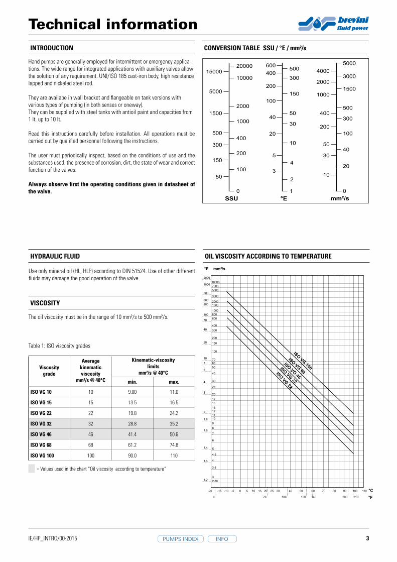
The oil viscosity must be in the range of 10 mm²/s to 500 mm²/s.
Table 1: ISO viscosity grades
Kinematic-viscosity limits
mm²/s @ 40°C
Averagekinematicviscosity
mm²/s @ 40°C
Viscositygrade
= Values used in the chart “Oil viscosity according to temperature”
OIL VISCOSITy ACCORDING TO TEMPERATURE
CONVERSION TABLE SSU / °E / mm²/s
HyDRAULIC FLUID
Use only mineral oil (HL, HLP) according to DIN 51524. Use of other different fluids may damage the good operation of the valve.
Technical information
Hand pumps are generally employed for intermittent or emergency applica-tions. The wide range for integrated applications with auxiliary valves allow the solution of any requirement. UNI/ISO 185 cast-iron body, high resistance lapped and nickeled steel rod.
They are availabe in wall bracket and flangeable on tank versions with various types of pumping (in both senses or oneway).They can be supplied with steel tanks with antioil paint and capacities from 1 lt. up to 10 lt.
Read this instructions carefully before installation. All operations must be carried out by qualified personnel following the instructions.
The user must periodically inspect, based on the conditions of use and the substances used, the presence of corrosion, dirt, the state of wear and correct function of the valves.
Always observe first the operating conditions given in datasheet of the valve.
INFOPUMPS INDEX

4IE/HP_INTRO/00-2015
Type of systemType of valve
Oil filtration recommendationsCleanliness class
recommendedAbsolute filtration
micron rating ( ** )
ISO 4406 : 1999 NAS 1638 ( * )
Systems or components operating at HIGH PRESSURE > 250 bar (3600 psi)HIGH DUTY CYCLE APPLICATIONSSystems or components with LOW dirt tolerance
18 / 16 / 13 7 - 8 5
Systems or components operating at MEDIUM / HIGH PRESSURESystems and components with moderate dirt tolerance
19 / 17 / 14 9 10
Systems or components operating at LOW PRESSURE < 100 bar (1500 psi)LOW DUTY CYCLE APPLICATIONSSystems and components with GOOD dirt tolerance
20 / 18 / 15 10 - 11 20
Type SI units Alternative units Conversion factor
Force Newton (N) [kgm/s²]Kilogram force (kgf) 1 kgf = 9.807 Npound force (lbf) [lbf/s²] 1 lgf = 4.448 N
Lengthmillimeter (mm) [10 m] inch (in) 1 in = 25.4 mmmeter (km) [1000 m] yard (yd) [3ft] 1 m = 1.0936 ydkilometer (km) [1000 m] mile (mile) [1760 yd] 1 mile = 1.609 km
Torque Newton meter (Nm) pound force.feet (lbf.ft) 1 lbf.ft = 1.356 Nm
Power kiloWatt (kW) [1000 Nm/s]horsepower (hp) 1 kW = 1.341 hpmetric horsepower (CV) 1 kW = 1.36 CV
Pressure MegaPascal (MPa) [ N/mm²]bar 1 MPa = 10 barpsi (lbf/ln²) 1 MPa = 145 psiton/f/ln² 1 ton/f/ln² = 15.45 MPa
Flow rate liter/min (l/min)UK gal/min 1 UK gal/min = 4.546 l/minUS gal/min 1 US gal/min = 3.785 l/min
Temperature Degrees Celsius (°C) Farenheit (°F) 1°F = 1.8 °C+32
Ambient temperature range: -25°C to +60°CFluid temperature range (NBR seals): -25°C to +75°C
WORKING TEMPERATURES
CONVERSION CHART
* Contamination class NAS 1638: it is determined by counting the total particles of different size ranges contained in 100 ml of fluid.
** Absolute filtration: it is a characteristic of each filter, it refers the size (in micron) of the largest sperical particle wich may pass through the filter.
Table 2: Reccomanded contamination level.
Observe the functional limits indicated in the technical catalogueOn a periodic basis and based on the conditions of use, check for cleanliness, state of wear or fractures and correct performance of the pump.If the O-rings are damaged, replace them with those supplied by the manu-facturer.To assure the best working conditions at all time, check the oiland replace it periodically (after the first 100 working hours and then after every 2000 working hours or at least once every year).
Attention: all installation and maintenance intervention must be per-formed by qualified staff.
USE AND MAINTENANCE
TRANSPORT AND STORAGE
The pump must be handled with care to avoid damage caused by impact, which could compromise its efficiency.In the case of storage, keep the pump in a dry place and protect against dust and corrosive substances.When storing for periods of more than 6 months, fill the pump with preserving oils and seal it.
For the general warranty and supply conditions, please consult the specific sales contract or the “General terms and conditions of sale” document IOP 7-2-05. Downloaded from the website: www.brevinifluidpower.com
WARRANTy AND SUPPLy CONDITIONS
Technical informationCONTAMINATION
Oil contamination is the main cause of faults and malfunction in hydraulic systems. Abrasive particles in the fluid erode or block moving parts, leading to system malfunction.
However, accurate filtering does guarantee reliability and a long life to all the system’s hydraulic parts. Reliable performance and long working life for all oil-pressure parts is assured by maintaining the level of fluid contamination within the limits specified in the data sheet of the pump.
Hydraulic fluid must also be cleaned properly before filling the hydraulic circuit, especially when commissioning a new system, as this is when the oil contami-nation generally peaks due to its flushing effect on the components, and the running-in of the pump.
The standard ISO 4406:1999 defines the contamination level with three num-bers that relate with the number of particles of average dimension equal or greater than 4 µm, 6 µm e 14 µm, in 1 ml of fluid.
In following table there is a reference to reccomended contamination level and correspondence with old NAS 1638 standard.
INFOPUMPS INDEX

5
PM 06/12/25/45 S** 00 2
D
E
3/8 G
A
95
50
92,5
155,5
25
50
61,5
106,5
30
27
B
C
OIL
OIL
IE/HP_PM06-12-25-45S_002/01-2015
PM06
S**(pag. 25) 00 2
253 166 34 26 31 6 6,970 420 500 2,90
pag. 32
PM12 253 166 34 26 31 12 12,095 220 380 2,90
PM25 273 172 34 30 30 25 25,280 120 350 2,95
PM45 283 172 40 45 33 45 44,532 80 280 3,00
PM 06
PM 12
PM 45
PM 25
HAND PUMP WITH RELEASE HAND KNOB
With release hand knobDouble acting hand pump for single acting cylinderFor fixing to tank
Specifications:• Cast iron body• Piston treated with Niploy• White zinc plated support lever• Lever connection Ø 27• White zinc plated external parts• Standard colour black• Oil tank mounting kit included
EFFORT DIAGRAM HyDRAULIC DIAGRAM
pin in D (distance between centers 40 mm) PM 06 - PM 12pin in E (distance between centers 51 mm) PM 25 - PM 45
EFFO
RT B
Y M
EAN
S OF
LEV
ER 6
00 m
m
PRESSURE
N° 4 clamp screw M8
OPTIMUM EFFORT
Ordering codeA
mmB
mmC
mmD°
E°
Nominal displac. cm³
Actual displac. cm³
Pressure BARMass
kg LeverType Tank Variant No.
serie Optimal Max
INFOPUMPS INDEX

6
PM 06/12/25/45 S** 02 2
3/8 GA
D
E
27
50
95
92,5
155,5
25
50
61,5
114
30
B
C
OIL
OIL
IE/HP_PM06-12-25-45S_022/01-2015
PM06
S**(pag. 25) 02 2
253 166 34 26 31 6 6,970 420 500 2,90
pag. 32
PM12 253 166 34 26 31 12 12,095 220 380 2,90
PM25 273 172 34 30 30 25 25,280 120 350 2,95
PM45 283 172 40 45 33 45 44,532 80 280 3,00
PM 06
PM 12
PM 45
PM 25
HAND PUMP WITH RELIEF VALVE AND RELEASE HAND KNOB
With pressure relief valveWith release hand knobDouble acting hand pump for single cylinderFor fixing to tank
Specifications:• Cast iron body• Piston treated with Niploy• White zinc plated support lever• Lever connection Ø 27• White zinc plated external parts• Standard colour black• Oil tank mounting kit included• Pressure relief valve standard setting: 100 bar
(others settings upon request).
EFFORT DIAGRAM HyDRAULIC DIAGRAM
pin in D (distance between centers 40 mm) PM 06 - PM 12pin in E (distance between centers 51 mm) PM 25 - PM 45
EFFO
RT B
Y M
EAN
S OF
LEV
ER 6
00 m
m
PRESSURE
N° 4 clamp screw M8
OPTIMUM EFFORT
Ordering codeA
mmB
mmC
mmD°
E°
Nominal displac. cm³
Actual displac. cm³
Pressure BARMass
kg LeverType Tank Variant No.
serie Optimal Max
INFOPUMPS INDEX

7
PM 06/12/25/45 S** 03 2
D
E
3/8 G
30
61,5
106,5
25
50
BA
C
27
50
95
56,5
119,5
OIL
OIL
IE/HP_PM06-12-25-45S_032/02-2016
PM06
S**(pag. 25) 03 2
253 166 34 26 31 6 6,970 420 500 2,90
pag. 32
PM12 253 166 34 26 31 12 12,095 220 380 2,90
PM25 273 172 34 30 30 25 25,280 120 350 2,95
PM45 283 172 40 45 33 45 44,532 80 280 3,00
PM 06
PM 12
PM 45
PM 25
HAND PUMP WITHOUT RELEASE HAND KNOB
Without release hand knobDouble acting hand pump for single For fixing to tank
Specifications:• Cast iron body• Piston treated with Niploy• White zinc plated support lever• Lever connection Ø 27• White zinc plated external parts• Standard colour black• Oil tank mounting kit included
EFFORT DIAGRAM HyDRAULIC DIAGRAM
pin in D (distance between centers 40 mm) PM 06 - PM 12pin in E (distance between centers 51 mm) PM 25 - PM 45
EFFO
RT B
Y M
EAN
S OF
LEV
ER 6
00 m
m
PRESSURE
N° 4 clamp screw M8
OPTIMUM EFFORT
Ordering codeA
mmB
mmC
mmD°
E°
Nominal displac. cm³
Actual displac. cm³
Pressure BARMass
kg LeverType Tank Variant No.
serie Optimal Max
INFOPUMPS INDEX

8
PM 06/12/25/45 S** 14 2
IE/HP_PM06-12-25-45S_142/01-2015
PM06
S**(pag. 25) 14 2
253 166 34 26 31 6 6,970 420 500 2,90
pag. 32
PM12 253 166 34 26 31 12 12,095 220 380 2,90
PM25 273 172 34 30 30 25 25,280 120 350 2,95
PM45 283 172 40 45 33 45 44,532 80 280 3,00
PM 06
PM 12
PM 45
PM 25
D
E
3/8 G
30
61,5
114
25
50
BA
C
27
50
95
56,5
119,5
OIL
OIL
HAND PUMP WITH RELIEF VALVE WITHOUT RELEASE HAND KNOB
Without release hand knobWith pressure relief valveDouble acting hand pump for single For fixing to tank
Specifications:• Cast iron body• Piston treated with Niploy• White zinc plated support lever• Lever connection Ø 27• White zinc plated external parts• Standard colour black• Oil tank mounting kit included• Pressure relief valve standard setting: 100 bar
(others settings upon request).
EFFORT DIAGRAM HyDRAULIC DIAGRAM
pin in D (distance between centers 40 mm) PM 06 - PM 12pin in E (distance between centers 51 mm) PM 25 - PM 45
EFFO
RT B
Y M
EAN
S OF
LEV
ER 6
00 m
m
PRESSURE
N° 4 clamp screw M8
OPTIMUM EFFORT
Ordering codeA
mmB
mmC
mmD°
E°
Nominal displac. cm³
Actual displac. cm³
Pressure BARMass
kg LeverType Tank Variant No.
serie Optimal Max
INFOPUMPS INDEX

9
PM 06/12/25/45 S** 11 2
3/8 G
30
25
50
61,5
106,5
BA
C
50
95
27
168,5
231,5
OIL
OIL
D
E
IE/HP_PM06-12-25-45S_112/01-2015
PM06
S**(pag. 25) 11 2
253 166 34 26 31 6 6,970 420 500 2,90
pag. 32
PM12 253 166 34 26 31 12 12,095 220 380 2,90
PM25 273 172 34 30 30 25 25,280 120 350 2,95
PM45 283 172 40 45 33 45 44,532 80 280 3,00
PM 06
PM 12
PM 45
PM 25
HAND PUMP WITH NORMALLy CLOSED MANIPULATOR
With normally closed manipulatorDouble acting hand pump for single acting cylinderFor fixing to tank
Specifications:• Cast iron body• Piston treated with Niploy• White zinc plated support lever• Lever connection Ø 27• White zinc plated external parts• Standard colour black• Oil tank mounting kit included
EFFORT DIAGRAM HyDRAULIC DIAGRAM
pin in D (distance between centers 40 mm) PM 06 - PM 12pin in E (distance between centers 51 mm) PM 25 - PM 45
EFFO
RT B
Y M
EAN
S OF
LEV
ER 6
00 m
m
PRESSURE
N° 4 clamp screw M8
OPTIMUM EFFORT
Ordering codeA
mmB
mmC
mmD°
E°
Nominal displac. cm³
Actual displac. cm³
Pressure BARMass
kg LeverType Tank Variant No.
serie Optimal Max
INFOPUMPS INDEX

10
PM 06/12/25/45 S** 12 2
IE/HP_PM06-12-25-45S_122/01-2015
PM06
S**(pag. 25) 12 2
253 166 34 26 31 6 6,970 420 500 2,90
pag. 32
PM12 253 166 34 26 31 12 12,095 220 380 2,90
PM25 273 172 34 30 30 25 25,280 120 350 2,95
PM45 283 172 40 45 33 45 44,532 80 280 3,00
PM 06
PM 12
PM 45
PM 25
3/8 G
30
25
50
61,5
114
BA
C
50
95
27
168,5
231,5
OIL
OIL
D
E
HAND PUMP WITH RELIEF VALVE AND NORMALLy CLOSED MANIPULATOR
With normally closed manipulatorWith pressure relief valveDouble acting hand pump for single acting cylinderFor fixing to tank
Specifications:• Cast iron body• Piston treated with Niploy• White zinc plated support lever• Lever connection Ø 27• White zinc plated external parts• Standard colour black
• Oil tank mounting kit included• Pressure relief valve standard setting: 100
bar (others settings upon request).
EFFORT DIAGRAM HyDRAULIC DIAGRAM
pin in D (distance between centers 40 mm) PM 06 - PM 12pin in E (distance between centers 51 mm) PM 25 - PM 45
EFFO
RT B
Y M
EAN
S OF
LEV
ER 6
00 m
m
PRESSURE
N° 4 clamp screw M8
OPTIMUM EFFORT
Ordering codeA
mmB
mmC
mmD°
E°
Nominal displac. cm³
Actual displac. cm³
Pressure BARMass
kg LeverType Tank Variant No.
serie Optimal Max
INFOPUMPS INDEX

11
PMI 06/12/25/45 S** 04 2
D
E
3/8 G 3/8 G
19
19
61,5
123
25
50
BA
C
30
50
95
106
169
OIL
OIL OIL
IE/HP_PMI06-12-25-45S_042/01-2015
A1 0 2
B
PMI06
S**(pag. 25) 04 2
253 166 34 26 31 6 6,970 420 500 3,40
pag. 32
PMI12 253 166 34 26 31 12 12,095 220 380 3,40
PMI25 273 172 34 30 30 25 25,280 120 350 3,45
PMI45 283 172 40 45 33 45 44,532 80 280 3,50
PMI 45
PMI 25
PMI 12
PMI 06
HAND PUMP WITH 4/3 FLOW DIVIDER CLOSED CENTRE AND PRESSURE RELIEF VALVE
With 4/3 flow divider closed centreWith pressure relief valveDouble acting hand pump for a double acting cylinderFor fixing to tank
Specifications:• Cast iron body• Piston treated with Niploy• White zinc plated support lever• Lever connection Ø 27• White zinc plated external parts• Standard colour black• Oil tank mounting kit included• Pressure relief valve standard setting: 100 bar
(others settings upon request).
EFFORT DIAGRAM HyDRAULIC DIAGRAM
pin in D (distance between centers 40 mm) PMI 06 - PMI 12pin in E (distance between centers 51 mm) PMI 25 - PMI 45
EFFO
RT B
Y M
EAN
S OF
LEV
ER 6
00 m
m
PRESSURE
N° 4 clamp screw M8
OPTIMUM EFFORT
Ordering codeA
mmB
mmC
mmD°
E°
Nominal displac. cm³
Actual displac. cm³
Pressure BARMass
kg LeverType Tank Variant No.
serie Optimal Max
INFOPUMPS INDEX

12
PMI 06/12/25/45 S** 05 2
D
E
3/8 G 3/8
G
19
19
61,5
123
25
50
BA
C
30
50
95
106
169
OIL
OIL OIL
IE/HP_PMI06-12-25-45S_052/01-2015
PMI06
S**(pag. 25) 05 2
253 166 34 26 31 6 6,970 420 500 3,40
pag. 32
PMI12 253 166 34 26 31 12 12,095 220 380 3,40
PMI25 273 172 34 30 30 25 25,280 120 350 3,45
PMI45 283 172 40 45 33 45 44,532 80 280 3,50
PMI 45
PMI 25
PMI 12
PMI 06
A1 0 2
B
HAND PUMP WITH 4/3 FLOW DIVIDER CLOSED CENTRE AND RELEASE LEVER
With 4/3 flow divider closed centreWith release leverDouble acting hand pump for a double acting cylinderFor fixing to tank
Specifications:• Cast iron body• Piston treated with Niploy• White zinc plated support lever• Lever connection Ø 27• White zinc plated external parts• Standard colour black• Oil tank mounting kit included
EFFORT DIAGRAM HyDRAULIC DIAGRAM
pin in D (distance between centers 40 mm) PMI 06 - PMI 12pin in E (distance between centers 51 mm) PMI 25 - PMI 45
EFFO
RT B
Y M
EAN
S OF
LEV
ER 6
00 m
m
PRESSURE
N° 4 clamp screw M8
OPTIMUM EFFORT
Ordering codeA
mmB
mmC
mmD°
E°
Nominal displac. cm³
Actual displac. cm³
Pressure BARMass
kg LeverType Tank Variant No.
serie Optimal Max
INFOPUMPS INDEX

13
PMI 06/12/25/45 S** 00 2
A1 0 2
B
D
E
3/8 G 3/8 G
61,5
123
25
50
BA
19
19 C
30
50
95
106
169
OIL
OILOIL
IE/HP_PMI06-12-25-45S_002/01-2015
PMI 45
PMI 25
PMI 12
PMI 06
PMI06
S**(pag. 25) 00 2
253 166 34 26 31 6 6,970 420 500 3,40
pag. 32
PMI12 253 166 34 26 31 12 12,095 220 380 3,40
PMI25 273 172 34 30 30 25 25,280 120 350 3,45
PMI45 283 172 40 45 33 45 44,532 80 280 3,50
HAND PUMP WITH 4/3 FLOW DIVIDER CLOSED CENTRE
With 4/3 flow divider closed centreDouble acting hand pump for a double acting cylinderFor fixing to tank
Specifications:• Cast iron body• Piston treated with Niploy• White zinc plated support lever• Lever connection Ø 27• White zinc plated external parts• Standard colour black• Oil tank mounting kit included
EFFORT DIAGRAM HyDRAULIC DIAGRAM
pin in D (distance between centers 40 mm) PMI 06 - PMI 12pin in E (distance between centers 51 mm) PMI 25 - PMI 45
EFFO
RT B
Y M
EAN
S OF
LEV
ER 6
00 m
m
PRESSURE
N° 4 clamp screw M8
OPTIMUM EFFORT
Ordering codeA
mmB
mmC
mmD°
E°
Nominal displac. cm³
Actual displac. cm³
Pressure BARMass
kg LeverType Tank Variant No.
serie Optimal Max
INFOPUMPS INDEX

14
PMI 06/12/25/45 S** 06 2
IE/HP_PMI06-12-25-45S_062/01-2015
PMI06
S**(pag. 25) 06 2
253 166 34 26 31 6 6,970 420 500 3,40
pag. 32
PMI12 253 166 34 26 31 12 12,095 220 380 3,40
PMI25 273 172 34 30 30 25 25,280 120 350 3,45
PMI45 283 172 40 45 33 45 44,532 80 280 3,50
PMI 45
PMI 25
PMI 12
PMI 06
D
E
3/8 G 3/8
G
19
19
61,5
123
25
50
BA
C
30
50
95
106
169
OIL
OIL OIL
A1 0 2
B
HAND PUMP WITH 4/3 FLOW DIVIDER CLOSED CENTRE RELEASE LEVER AND PRESSURE RELIEF VALVE
With 4/3 flow divider closed centreWith release leverWith pressure relief valveDouble acting hand pump for a double acting cylinderFor fixing to tank
Specifications:• Cast iron body• Piston treated with Niploy• White zinc plated support lever• Lever connection Ø 27• White zinc plated external parts• Standard colour black• Oil tank mounting kit included• Pressure relief valve standard setting: 100 bar
(others settings upon request).
EFFORT DIAGRAM HyDRAULIC DIAGRAM
pin in D (distance between centers 40 mm) PMI 06 - PMI 12pin in E (distance between centers 51 mm) PMI 25 - PMI 45
EFFO
RT B
Y M
EAN
S OF
LEV
ER 6
00 m
m
PRESSURE
N° 4 clamp screw M8
OPTIMUM EFFORT
Ordering codeA
mmB
mmC
mmD°
E°
Nominal displac. cm³
Actual displac. cm³
Pressure BARMass
kg LeverType Tank Variant No.
serie Optimal Max
INFOPUMPS INDEX

15
PMB 06/12/25/45 S** 00 2
A
1 0 2
B
D
E
1/4 G 1/4 G
30
30
25
50
55
110
BA
C
27
50
95
107
170
OIL
OILOIL
IE/HP_PMB06-12-25-45S_002/01-2015
PMB 45
PMB 25
PMB 12
PMB 06
PMB06
S**(pag. 25) 00 2
253 166 34 26 31 6 6,970 420 500 3,40
pag. 32
PMB12 253 166 34 26 31 12 12,095 220 380 3,40
PMB25 273 172 34 30 30 25 25,280 120 350 3,45
PMB45 283 172 40 45 33 45 44,532 80 280 3,50
HAND PUMP WITH 4/3 FLOW DIVIDER, DUAL PILOT CHECK VALVE AND BRAKES
With 4/3 flow dividerWith dual pilot check valveWith brakesDouble acting hand pump for a double acting cylinderFor fixing to tank
Specifications:• Cast iron body• Piston treated with Niploy• White zinc plated support lever• Lever connection Ø 27• White zinc plated external parts• Standard colour black• Oil tank mounting kit included• With hydraulic brakes to operate under 50 bar
pressure.
EFFORT DIAGRAM HyDRAULIC DIAGRAM
pin in D (distance between centers 40 mm) PMB 06 - PMB 12pin in E (distance between centers 51 mm) PMB 25 - PMB 45
EFFO
RT B
Y M
EAN
S OF
LEV
ER 6
00 m
m
PRESSURE
N° 4 clamp screw M8
OPTIMUM EFFORT
pilot ratio 5:1
Ordering codeA
mmB
mmC
mmD°
E°
Nominal displac. cm³
Actual displac. cm³
Pressure BARMass
kg LeverType Tank Variant No.
serie Optimal Max
INFOPUMPS INDEX

16
PMB 06/12/25/45 S** 07 2
PMB 45
PMB 25
PMB 12
PMB 06
PMB06
S**(pag. 25) 07 2
253 166 34 26 31 6 6,970 420 500 3,40
pag. 32
PMB12 253 166 34 26 31 12 12,095 220 380 3,40
PMB25 273 172 34 30 30 25 25,280 120 350 3,45
PMB45 283 172 40 45 33 45 44,532 80 280 3,50
IE/HP_PMB06-12-25-45S_072/01-2015
D
E
1/4 G 1/4 G
30
30
25
50
55
110
BA
C
27
50
95
107
170
OIL
OILOIL
A
1 0 2
B
HAND PUMP WITH 4/3 FLOW DIVIDER, DUAL PILOT CHECK VALVE,BRAKESAND PRESSURE RELIEF VALVE IN “A”
With 4/3 flow dividerWith dual pilot check valveWith brakesWith pressure relief valve in “A”Double acting hand pump for a double acting cylinderFor fixing to tank
Specifications:• Cast iron body• Piston treated with Niploy• White zinc plated support lever• Lever connection Ø 27• White zinc plated external parts• Standard colour black• Oil tank mounting kit included• With hydraulic brakes to operate under 50 bar
pressure• Pressure relief valve standard setting: 100 bar
(others settings upon request).
EFFORT DIAGRAM HyDRAULIC DIAGRAM
pin in D (distance between centers 40 mm) PMB 06 - PMB 12pin in E (distance between centers 51 mm) PMB 25 - PMB 45
EFFO
RT B
Y M
EAN
S OF
LEV
ER 6
00 m
m
PRESSURE
N° 4 clamp screw M8
OPTIMUM EFFORT
pilot ratio 5:1
Ordering codeA
mmB
mmC
mmD°
E°
Nominal displac. cm³
Actual displac. cm³
Pressure BARMass
kg LeverType Tank Variant No.
serie Optimal Max
INFOPUMPS INDEX

17
PMB 06/12/25/45 S** 08 2
PMB 45
PMB 25
PMB 12
PMB 06
PMB06
S**(pag. 25) 08 2
253 166 34 26 31 6 6,970 420 500 3,40
pag. 32
PMB12 253 166 34 26 31 12 12,095 220 380 3,40
PMB25 273 172 34 30 30 25 25,280 120 350 3,45
PMB45 283 172 40 45 33 45 44,532 80 280 3,50
IE/HP_PMB06-12-25-45S_082/01-2015
D
E
1/4 G 1/4 G
30
30
25
50
55
110
BA
C
27
50
95
107
170
OIL
OILOIL
A
1 0 2
B
HAND PUMP WITH 4/3 FLOW DIVIDER, DUAL PILOT CHECK VALVE,BRAKESAND PRESSURE RELIEF VALVE IN “B”
With 4/3 flow dividerWith dual pilot check valveWith brakesWith pressure relief valve in”B”Double acting hand pump for a double acting cylinderFor fixing to tank
Specifications:• Cast iron body• Piston treated with Niploy• White zinc plated support lever• Lever connection Ø 27• White zinc plated external parts• Standard colour black• Oil tank mounting kit included• With hydraulic brakes to operate under 50 bar
pressure• Pressure relief valve standard setting: 100 bar
(others settings upon request).
EFFORT DIAGRAM HyDRAULIC DIAGRAM
pin in D (distance between centers 40 mm) PMB 06 - PMB 12pin in E (distance between centers 51 mm) PMB 25 - PMB 45
EFFO
RT B
Y M
EAN
S OF
LEV
ER 6
00 m
m
PRESSURE
N° 4 clamp screw M8
OPTIMUM EFFORT
pilot ratio 5:1
Ordering codeA
mmB
mmC
mmD°
E°
Nominal displac. cm³
Actual displac. cm³
Pressure BARMass
kg LeverType Tank Variant No.
serie Optimal Max
INFOPUMPS INDEX

18
PMB 06/12/25/45 S** 09 2
PMB 45
PMB 25
PMB 12
PMB 06
PMB06
S**(pag. 25) 09 2
253 166 34 26 31 6 6,970 420 500 3,40
pag. 32
PMB12 253 166 34 26 31 12 12,095 220 380 3,40
PMB25 273 172 34 30 30 25 25,280 120 350 3,45
PMB45 283 172 40 45 33 45 44,532 80 280 3,50
IE/HP_PMB06-12-25-45S_092/01-2015
D
E
1/4 G 1/4 G
30
30
25
50
55
110
BA
C
27
50
95
107
170
OIL
OILOIL
A
1 0 2
B
HAND PUMP WITH 4/3 FLOW DIVIDER, DUAL PILOT CHECK VALVE,BRAKESAND PRESSURE RELIEF VALVE IN “A” AND “B”
With 4/3 flow dividerWith dual pilot check valve in “A” and “B”With brakesWith pressure relief valveDouble acting hand pump for a double acting cylinderFor fixing to tank
Specifications:• Cast iron body• Piston treated with Niploy• White zinc plated support lever• Lever connection Ø 27• White zinc plated external parts• Standard colour black• Oil tank mounting kit included• With hydraulic brakes to operate under 50 bar
pressure• Pressure relief valve standard setting: 100 bar
(others settings upon request).
EFFORT DIAGRAM HyDRAULIC DIAGRAM
pin in D (distance between centers 40 mm) PMB 06 - PMB 12pin in E (distance between centers 51 mm) PMB 25 - PMB 45
EFFO
RT B
Y M
EAN
S OF
LEV
ER 6
00 m
m
PRESSURE
N° 4 clamp screw M8
OPTIMUM EFFORT
pilot ratio 5:1
Ordering codeA
mmB
mmC
mmD°
E°
Nominal displac. cm³
Actual displac. cm³
Pressure BARMass
kg LeverType Tank Variant No.
serie Optimal Max
INFOPUMPS INDEX

19
1PMS 20/30/40 S** 00 2
1/4 G
30
25
50
60,5
100,5
BA
27
C
50
95
91
154
OIL
OIL
D
E
IE/HP_1PMS20-30-40S_002/00-2015
1PMS20 S**
(pag. 25) 00 2
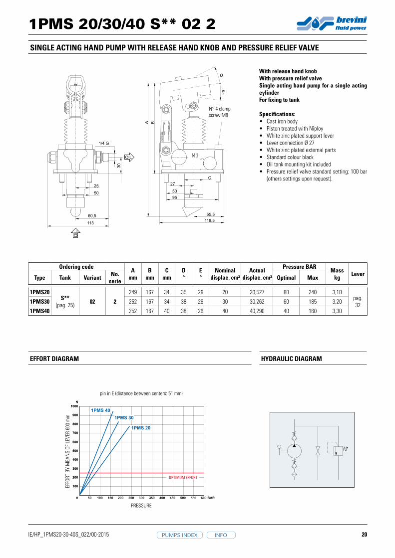
249 167 34 35 29 20 20,527 80 240 3,10pag. 321PMS30 252 167 34 38 26 30 30,262 60 185 3,20
1PMS40 252 167 40 38 26 40 40,290 40 160 3,30
1PMS 40
1PMS 30
1PMS 20
SINGLE ACTING HAND PUMP WITH RELEASE HAND KNOB
With release hand knobSingle acting hand pump for a single acting cylinderFor fixing to tank
Specifications:• Cast iron body• Piston treated with Niploy• White zinc plated support lever• Lever connection Ø 27• White zinc plated external parts• Standard colour black• Oil tank mounting kit included.
EFFORT DIAGRAM HyDRAULIC DIAGRAM
EFFO
RT B
Y M
EAN
S OF
LEV
ER 6
00 m
m
PRESSURE
OPTIMUM EFFORT
pin in E (distance between centers: 51 mm)
N° 4 clamp screw M8
Ordering codeA
mmB
mmC
mmD°
E°
Nominal displac. cm³
Actual displac. cm³
Pressure BARMass
kg LeverType Tank Variant No.
serie Optimal Max
INFOPUMPS INDEX
20
1PMS 20/30/40 S** 02 2
IE/HP_1PMS20-30-40S_022/00-2015
1PMS20 S**
(pag. 25) 02 2
249 167 34 35 29 20 20,527 80 240 3,10pag. 321PMS30 252 167 34 38 26 30 30,262 60 185 3,20
1PMS40 252 167 40 38 26 40 40,290 40 160 3,30
1PMS 40
1PMS 30
1PMS 20
1/4 G
30
25
50
60,5
113
BA
27
C
50
95
55,5
118,5
OIL
OIL
D
E
SINGLE ACTING HAND PUMP WITH RELEASE HAND KNOB AND PRESSURE RELIEF VALVE
With release hand knobWith pressure relief valveSingle acting hand pump for a single acting cylinderFor fixing to tank
Specifications:• Cast iron body• Piston treated with Niploy• White zinc plated support lever• Lever connection Ø 27• White zinc plated external parts• Standard colour black• Oil tank mounting kit included• Pressure relief valve standard setting: 100 bar
(others settings upon request).
EFFORT DIAGRAM HyDRAULIC DIAGRAM
EFFO
RT B
Y M
EAN
S OF
LEV
ER 6
00 m
m
PRESSURE
OPTIMUM EFFORT
pin in E (distance between centers: 51 mm)
N° 4 clamp screw M8
Ordering codeA
mmB
mmC
mmD°
E°
Nominal displac. cm³
Actual displac. cm³
Pressure BARMass
kg LeverType Tank Variant No.
serie Optimal Max
INFOPUMPS INDEX

21
1PMS 20/30/40 S** 03 2
IE/HP_1PMS20-30-40S_032/00-2015
1PMS20 S**
(pag. 25) 03 2
249 167 34 35 29 20 20,527 80 240 3,10pag. 321PMS30 252 167 34 38 26 30 30,262 60 185 3,20
1PMS40 252 167 40 38 26 40 40,290 40 160 3,30
1PMS 40
1PMS 30
1PMS 20
1/4 G
30
25
50
60,5
100,5
BA
27
C
50
95
55,5
118,5
OIL
OIL
D
E
SINGLE ACTING HAND PUMP WITHOUT RELEASE HAND KNOB
Without release hand knobSingle acting hand pump for a single acting cylinderFor fixing to tank
Specifications:• Cast iron body• Piston treated with Niploy• White zinc plated support lever• Lever connection Ø 27• White zinc plated external parts• Standard colour black• Oil tank mounting kit included
EFFORT DIAGRAM HyDRAULIC DIAGRAM
EFFO
RT B
Y M
EAN
S OF
LEV
ER 6
00 m
m
PRESSURE
OPTIMUM EFFORT
pin in E (distance between centers: 51 mm)
N° 4 clamp screw M8
Ordering codeA
mmB
mmC
mmD°
E°
Nominal displac. cm³
Actual displac. cm³
Pressure BARMass
kg LeverType Tank Variant No.
serie Optimal Max
INFOPUMPS INDEX

22
2PMS 08/15 S** 00 2
IE/2PMS08-15S_002/01-2015
2PMS08 S**(pag. 25) 00 2
30 26 8 8,042 180 360 3,20 pag. 322PMS15 30 26 15 15,205 110 350 3,20
2PMS 15
2PMS 08
D
E
1/4 G
72
112
25
50
47,5
246,5
93,5
110
38,5
95
SINGLE ACTING HAND PUMP WITH RELEASE HAND KNOB
With release hand knobSingle acting hand pump for a single acting cylinderFor fixing to tank
Specifications:• Cast iron body• Piston treated with Niploy• Iron cast support lever• Lever connection Ø 20• White zinc plated external parts• Standard colour black• Oil tank mounting kit included
EFFORT DIAGRAM HyDRAULIC DIAGRAM
EFFO
RT B
Y M
EAN
S OF
LEV
ER 5
00 m
m
PRESSURE
OPTIMUM EFFORT
N° 4 clamp screw M8
Ordering codeD°
E°
Nominal displac. cm³
Actual displac. cm³
Pressure BARMass
kg LeverType Tank Variant No.
serie Optimal Max
INFOPUMPS INDEX

23
2PMS 08/15 S** 02 2
IE/2PMS08-15S_022/01-2015
2PMS08 S**(pag. 25) 02 2
30 26 8 8,042 180 360 3,20 pag. 322PMS15 30 26 15 15,205 110 350 3,20
2PMS 15
2PMS 08
D
E
1/4 G
72
124
25
50
47,5
246,5
93,5
110
38,5
95
SINGLE ACTING HAND PUMP WITH RELEASE HAND KNOB AND PRESSURE RELIEF VALVE
With release hand knobWith pressure relief valveSingle acting hand pump for a single acting cylinderFor fixing to tank
Specifications:• Cast iron body• Piston treated with Niploy• Iron cast support lever• Lever connection Ø 20• White zinc plated external parts• Standard colour black• Oil tank mounting kit included• Pressure relief valve standard setting:
100 bar (others settings upon request).
EFFORT DIAGRAM HyDRAULIC DIAGRAM
EFFO
RT B
Y M
EAN
S OF
LEV
ER 5
00 m
m
PRESSURE
OPTIMUM EFFORT
N° 4 clamp screw M8
Ordering codeD°
E°
Nominal displac. cm³
Actual displac. cm³
Pressure BARMass
kg LeverType Tank Variant No.
serie Optimal Max
INFOPUMPS INDEX

24
2PMS 08/15 S** 03 2
IE/2PMS08-15S_032/01-2015
2PMS08 S**(pag. 25) 03 2
30 26 8 8,042 180 360 3,20 pag. 322PMS15 30 26 15 15,205 110 350 3,20
D
E
1/4 G
40
80
25
50
47,5
246,593,5
110
38,5
95
2PMS 15
2PMS 08
SINGLE ACTING HAND PUMP WITHOUT RELEASE HAND KNOB
Without release hand knobSingle acting hand pump for a single acting cylinderFor fixing to tank
Specifications:• Cast iron body• Piston treated with Niploy• Iron cast support lever• Lever connection Ø 20• White zinc plated external parts• Standard colour black• Oil tank mounting kit included
EFFORT DIAGRAM HyDRAULIC DIAGRAM
EFFO
RT B
Y M
EAN
S OF
LEV
ER 5
00 m
m
PRESSURE
OPTIMUM EFFORT
N° 4 clamp screw M8
Ordering codeD°
E°
Nominal displac. cm³
Actual displac. cm³
Pressure BARMass
kg LeverType Tank Variant No.
serie Optimal Max
INFOPUMPS INDEX

25
A
D
15
90
C
2
B
50
95
45
5
59
20
M8
M8
M8
M8
R33
R33
S01 1 100 150 120 120 2,2 Ø10 x 85 mm SPM010001
S02 2 100 150 185 120 3,2 Ø10 x 114 mm SPM020001
S03 3 100 150 255 120 3,7 Ø10 x 180 mm SPM030001
15
90
C
D
A B
2
50
95
20
45
5
R33
R33
59
M8
M8
M8M8
S05 5 175 175 200 195 5,3 Ø10 x 156 mm SPM050001
S07 7 175 175 275 195 6,6 Ø10 x 215 mm SPM070001
S10 10 175 175 380 195 8,3 Ø10 x 325 mm SPM100001
IE/HP-TANKS/00-2015
PAINTED STEEL OIL TANKS FOR HAND PUMPS
Specifications:• Suction pipe included• Breather cap 1/4 G• Release cap 1/4 G• Standard colour black
Steel oil tanks
Ø9 through hole
Ø9 through holeØ9 through hole
Ø9 through hole
Specifications:• Suction pipe included• Breather cap 1/4 G• Release cap 1/4 G• Standard colour black
Ø9 through hole Ø9 through hole
Ø9 through holeØ9 through hole
Ordering code
Capacityliters
Amm
Bmm
Cmm
Dmm
Masskg
Suction pipe
Tank kit
Ordering code
Capacityliters
Amm
Bmm
Cmm
Dmm
Masskg
Suction pipe
Tank kit
INFOPUMPS INDEX
26
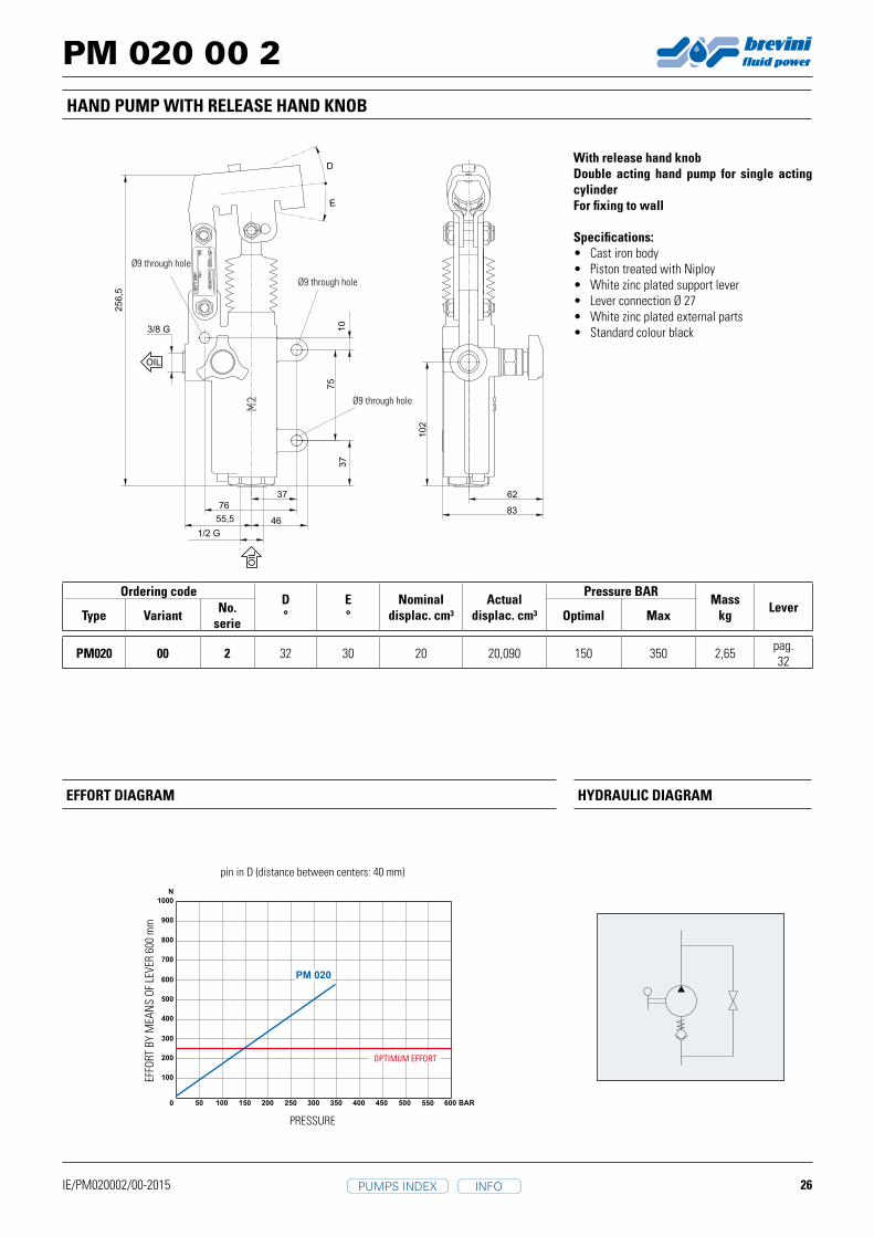
PM 020 00 2
83
6237
75
10
76
3/8 G
1/2 G
10
2
37
25
6,5
4655,5
OIL
OIL
D
E
IE/PM020002/00-2015
PM020 00 2 32 30 20 20,090 150 350 2,65 pag. 32
PM 020
HAND PUMP WITH RELEASE HAND KNOB
With release hand knobDouble acting hand pump for single acting cylinderFor fixing to wall
Specifications:• Cast iron body• Piston treated with Niploy• White zinc plated support lever• Lever connection Ø 27• White zinc plated external parts• Standard colour black
EFFORT DIAGRAM HyDRAULIC DIAGRAM
EFFO
RT B
Y M
EAN
S OF
LEV
ER 6
00 m
m
PRESSURE
OPTIMUM EFFORT
Ø9 through hole
Ø9 through hole
Ø9 through hole
pin in D (distance between centers: 40 mm)
Ordering codeD°
E°
Nominal displac. cm³
Actual displac. cm³
Pressure BARMass
kg LeverType Variant No.
serie Optimal Max
INFOPUMPS INDEX

27
PM 020 03 2
3/8 G
1/2 G
26,5
48
10
2
25
6,5
10
75
37
37
76
55,5 46
OIL
OIL
D
E
IE/PM020032/00-2015
PM020 03 2 32 30 20 20,090 150 350 2,65 pag. 32
PM 020
HAND PUMP WITHOUT RELEASE HAND KNOB
Without release hand knobDouble acting hand pump for single acting cylinderFor fixing to wall
Specifications:• Cast iron body• Piston treated with Niploy• White zinc plated support lever• Lever connection Ø 27• White zinc plated external parts• Standard colour black
EFFORT DIAGRAM HyDRAULIC DIAGRAM
EFFO
RT B
Y M
EAN
S OF
LEV
ER 6
00 m
m
PRESSURE
OPTIMUM EFFORT
Ø9 through hole
Ø9 through hole
Ø9 through hole
pin in D (distance between centers: 40 mm)
Ordering codeD°
E°
Nominal displac. cm³
Actual displac. cm³
Pressure BARMass
kg LeverType Variant No.
serie Optimal Max
INFOPUMPS INDEX

28
PM 020 10 2
42,5
64
10
2
3/8 G
1/2 G
25
6,5
37
76
4655,5
10
75
37
OIL
OIL
D
E
IE/PM020102/00-2015
PM020 10 2 32 30 20 20,090 150 350 2,65 pag. 32
PM 020
HAND PUMP WITH PRESSURE RELIEF VALVE WITHOUT RELEASE HAND KNOB
With pressure relief valveWithout release hand knobDouble acting hand pump for single acting cylinderFor fixing to wall
Specifications:• Cast iron body• Piston treated with Niploy• White zinc plated support lever• Lever connection Ø 27• White zinc plated external parts• Standard colour black• Pressure relief valve standard setting: 100 bar
(others settings upon request)
EFFORT DIAGRAM HyDRAULIC DIAGRAM
EFFO
RT B
Y M
EAN
S OF
LEV
ER 6
00 m
m
PRESSURE
OPTIMUM EFFORT
Ø9 through hole
Ø9 through hole
Ø9 through hole
pin in D (distance between centers: 40 mm)
Ordering codeD°
E°
Nominal displac. cm³
Actual displac. cm³
Pressure BARMass
kg LeverType Variant No.
serie Optimal Max
INFOPUMPS INDEX

29
PM 050 00 2
30
60
87
78
118
27
5
12
31/2 G
1/2 G
65
116
39
OIL
OIL
D
E
IE/PM050002/00-2015
PM050 00 2 38 37 50 43,825 80 280 3,40 pag. 32
PM 050
Without release hand knobDouble acting hand pump for single acting cylinderFor fixing to wall
Specifications:• Cast iron body• Piston treated with Niploy• White zinc plated support lever• Lever connection Ø 27• White zinc plated external parts• Standard colour black
EFFORT DIAGRAM HyDRAULIC DIAGRAM
pin in E (distance between centers: 51 mm)
EFFO
RT B
Y M
EAN
S OF
LEV
ER 6
00 m
m
PRESSURE
OPTIMUM EFFORT
Ø9 through holeØ9 through hole
Ø9 through hole
Ø9 through hole
HAND PUMP WITH RELEASE HAND KNOB
Ordering codeD°
E°
Nominal displac. cm³
Actual displac. cm³
Pressure BARMass
kg LeverType Variant No.
serie Optimal Max
INFOPUMPS INDEX

30
PM 050 03 2
1/2 G
1/2 G
27
5
65
116
12
3 87
39
30
60
42,5
82,5OIL
OIL
D
E
IE/PM050032/00-2015
PM050 03(1) 2 38 37 50 43,825 80 280 3,40 pag.
32
PM 050
Without release hand knobDouble acting hand pump for single acting cylinderFor fixing to wall
Specifications:• Cast iron body• Piston treated with Niploy• White zinc plated support lever• Lever connection Ø 27• White zinc plated external parts• Standard colour black.
EFFORT DIAGRAM HyDRAULIC DIAGRAM
pin in E (distance between centers: 51 mm)
EFFO
RT B
Y M
EAN
S OF
LEV
ER 6
00 m
m
PRESSURE
OPTIMUM EFFORT
Ø9 through holeØ9 through hole
Ø9 through hole
Ø9 through hole
HAND PUMP WITHOUT RELEASE HAND KNOB
Ordering codeD°
E°
Nominal displac. cm³
Actual displac. cm³
Pressure BARMass
kg LeverType Variant No.
serie Optimal Max
INFOPUMPS INDEX
31
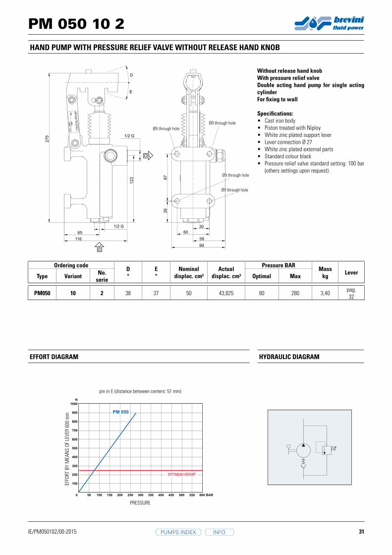
PM 050 10 2
1/2 G
1/2 G
27
5
12
3
65
116
87
39
30
60
59
99
OIL
OIL
D
E
IE/PM050102/00-2015
PM050 10 2 38 37 50 43,825 80 280 3,40 pag. 32
PM 050
Without release hand knobWith pressure relief valveDouble acting hand pump for single acting cylinderFor fixing to wall
Specifications:• Cast iron body• Piston treated with Niploy• White zinc plated support lever• Lever connection Ø 27• White zinc plated external parts• Standard colour black• Pressure relief valve standard setting: 100 bar
(others settings upon request).
EFFORT DIAGRAM HyDRAULIC DIAGRAM
pin in E (distance between centers: 51 mm)
EFFO
RT B
Y M
EAN
S OF
LEV
ER 6
00 m
m
PRESSURE
OPTIMUM EFFORT
Ø9 through holeØ9 through hole
Ø9 through hole
Ø9 through hole
HAND PUMP WITH PRESSURE RELIEF VALVE WITHOUT RELEASE HAND KNOB
Ordering codeD°
E°
Nominal displac. cm³
Actual displac. cm³
Pressure BARMass
kg LeverType Variant No.
serie Optimal Max
INFOPUMPS INDEX
32
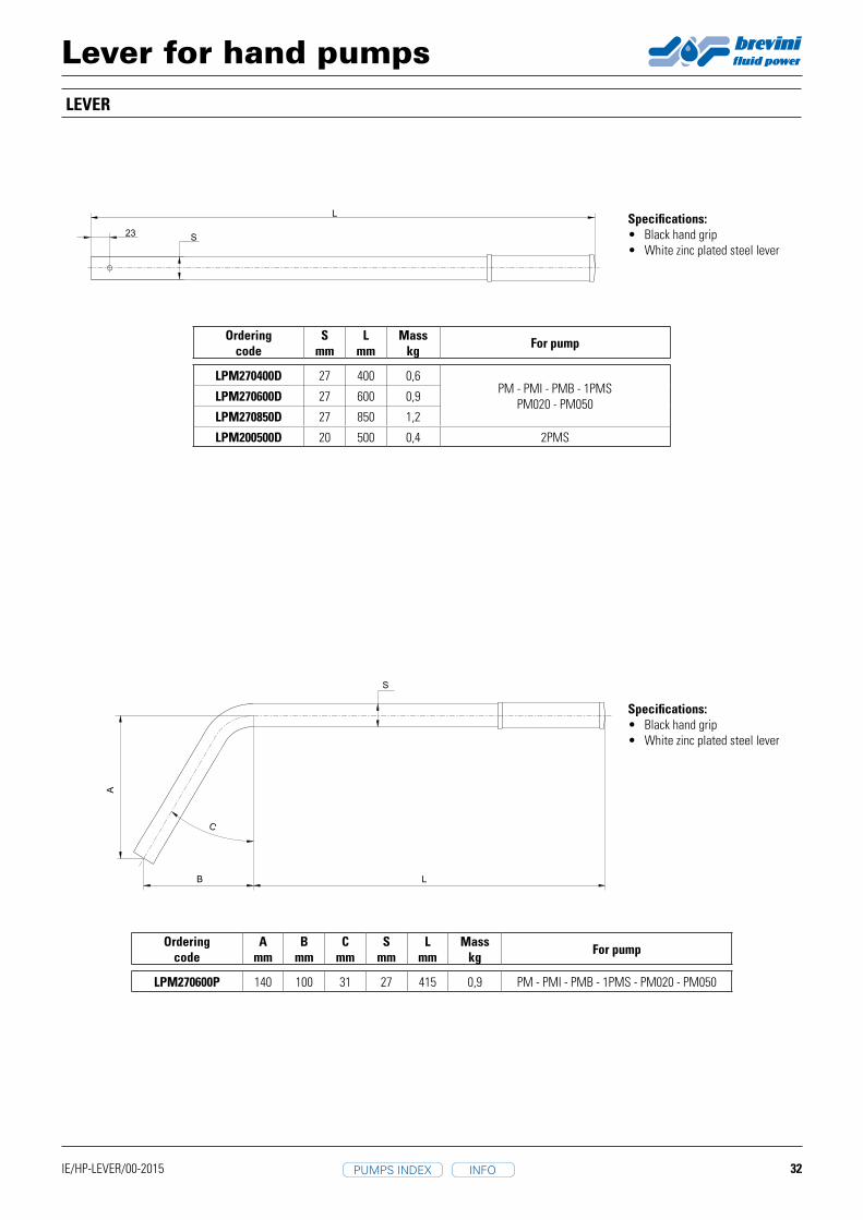
LPM270400D 27 400 0,6PM - PMI - PMB - 1PMS
PM020 - PM050LPM270600D 27 600 0,9
LPM270850D 27 850 1,2
LPM200500D 20 500 0,4 2PMS
23
L
S
IE/HP-LEVER/00-2015
LB
A
C
S
LPM270600P 140 100 31 27 415 0,9 PM - PMI - PMB - 1PMS - PM020 - PM050
LEVER
Lever for hand pumps
Ordering code
Smm
Lmm
Masskg For pump
Ordering code
Amm
Bmm
Cmm
Smm
Lmm
Masskg For pump
Specifications:• Black hand grip• White zinc plated steel lever
Specifications:• Black hand grip• White zinc plated steel lever
INFOPUMPS INDEX

33
PMP 12 0003
46
23
65
8
78
,5
10
5
651
76
Ø20
15
1/4 G
3/8 G
OIL
OIL
IE/PMP120003/00-2015
PMP120003 12 12,265 100 300 2,11
LPM250350D350
Ø 2
5
Ø 2
0,8
HAND PUMP
Without release hand knobDouble acting hand pump for a single acting cylinderFor fixing to a walll
Specifications:• Aluminium body• Piston treated with Niploy• White zinc plated support lever• Lever connection Ø 20• White zinc plated external parts
EFFORT DIAGRAM HyDRAULIC DIAGRAM
EFFO
RT B
Y M
EAN
S OF
LEV
ER 3
50 m
m
PRESSURE
OPTIMUM EFFORT
Ø6.5 through hole Ø6.5 through hole
Ø4.3 through hole
Ø6.5 through hole
Ordering code
Lever for PMP12 pump:• Black hand grip• White zinc plated steel lever
Ordering code
Nominal displac. cm³
Actual displac. cm³
Pressure BARMass
kgOptimal Max
INFOPUMPS INDEX

34
Note
INFOPUMPS INDEX

35
Note
INFOPUMPS INDEX
36
Note
INFOPUMPS INDEX


Brevini Fluid Power S.p.A.Via Moscova, 642124 Reggio Emilia - ItalyTel. +39 0522 270711Fax +39 0522 270660www.brevinifl uidpower.cominfo@brevinifl uidpower.com
Code DOC00069 - Rev. 02