haptic control console gui user guide 1 description
TRANSCRIPT

Haptic Control Console GUI User Guide 1 Description Haptic Control Console, HCC, is an evaluation and development suite for TI Haptic Drivers. HCC supports the evaluation of TI haptic drivers and 3rd party haptic actuators for developing advanced tactile feedback. You can connect TI Haptic Driver evaluation modules (EVM) to HCC via USB to setup, control and evaluate the entire device. HCC includes custom device control consoles, detailed register maps, and basic RAM management (for applicable devices). See board compatibility in table 1.1 below.
2 Features
Supports evaluation of haptic actuators including eccentric rotation mass motors (ERM), linear resonance actuators (LRA), piezos and solenoids.
Includes device management features including custom device control consoles, complete register map access, and RAM management.
Compatible with TI evaluation modules in table 1.1. Includes firmware update utility for compatible EVMs. Adapter board may be required.
3 Related Products TI Devices and corresponding Evaluation Modules (EVM)
DRV2510 – DRV2510EVM
DRV2511 – DRV2511EVM
DRV2604 - DRV2604EVM-CT
DRV2605 - DRV2605EVM-CT
DRV2604L - DRV2604LEVM-CT and DRV2604LDGSEVM-M
DRV2605L - DRV2605LEVM-CT, DRV2605LDGSEVM-M and DRV2605LEVM-MD
DRV2624 - DRV2624EVM-CT
DRV2625 - DRV2625EVM-CT
DRV2667 - DRV2667EVM-CT
USB2ANY – Documentation coming soon
4 Supported Evaluation Modules and Required Hardware
Evaluation Module (EVM) Additional Hardware Required
DRV2510Q1EVM None
DRV2511Q1EVM None
DRV2604EVM-CT USB2ANY
DRV2605EVM-CT USB2ANY
DRV2604LEVM-CT USB2ANY
DRV2605LEVM-CT USB2ANY
DRV2604LDGSEVM-M USB2ANY
DRV2605LDGSEVM-M USB2ANY
DRV2605LEVM-MD None
DRV2624EVM-CT None
DRV2624EVM-MINI USB2ANY
DRV2625EVM-CT None
DRV2625EVM-MINI USB2ANY
2
DRV2667EVM-CT USB2ANY
Table 1.1 – Compatible boards to use with HCC and the required hardware.
Table of Contents
1. Description…………………………………………………………………………………………..1 2. Features……………………………………………………………………………………………….1 3. Related Products………………………………………………………………………………….1 4. Supported Evaluation Modules and Required Hardware…………………….1 5. Getting Started: General Overview………………………………………………………2 6. Board Specific Information…………………………………………………………………..6
6.1 DRV2604/5 and DRV2604L/5L……………………………………………………....6 6.2 DR2605LEVM-MD………………………………………………………………………….7 6.3 DRV2624/5…………………………………………………………………………………….8 6.4 DRV2667………………………………………………………………………………….....12 6.5 DRV2510/1…………………………………………………………………………………..13
7. Suggested Changes…………………………………………………………………….……….14
5 Getting Started: General Overview
The Haptics Control Console (HCC) GUI can be downloaded from the following link:
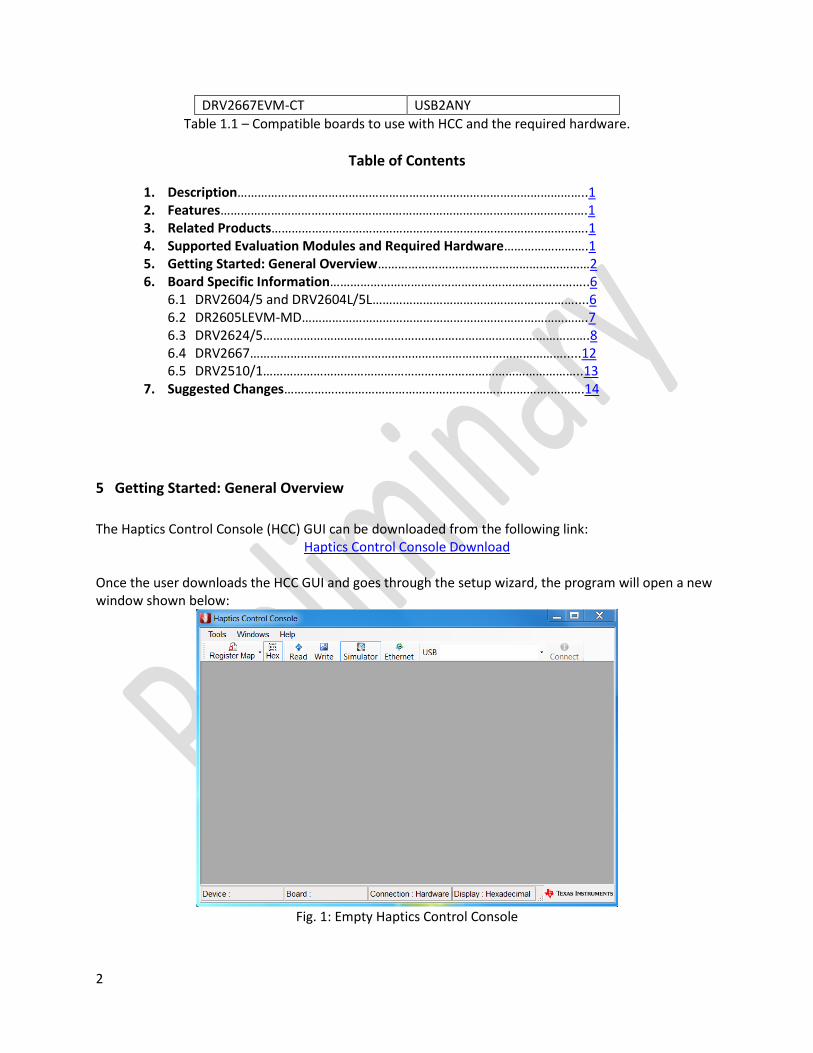
Haptics Control Console Download Once the user downloads the HCC GUI and goes through the setup wizard, the program will open a new window shown below:
Fig. 1: Empty Haptics Control Console

3
To see a list of the Haptic Drivers that the HCC GUI supports, select Tools -> Console.
Fig. 2: List of supported Haptic Drivers.
Next, the user should plug in their board. In this example, we will use the DRV2624EVM-CT, which can be plugged direct into the computer via micro USB. Once plugged in, it must be set to GUI mode by holding down the (+) button for approximately 3 seconds. The LEDs will flash and then the right half of the LEDs will remain on to indicate the board is in GUI mode. For other devices besides the DRV2625EVM-CT, DRV2510Q1EVM and DRV2511Q1EVM, the USB2ANY is required to transfer data between the haptic driver and the computer. Once the user plugs in the device (through the USB2ANY or directly to the computer), the name of the driver will appear next to USB (shown below in Fig. 3). The user must then select “Connect” in order to begin interacting with the device. At the bottom of the screen, the connection to the device is monitored.
Fig. 3: The HCC window once the board is plugged in via USB.
Note: at the top left of the console window, after DRVXXXX, it must say “USB” as boxed in red (shown below in Fig. 4). If instead it says “Simulator,” then the board is not fully connected and the user will not be able to program the device. If it does not read properly the first time, try removing the USB from the computer, restarting HCC program, and connecting again.

4
Fig. 4: The console window for the DRV2624 once the board is connected properly.
The console window for the DRV2624 is divided into three sections: Initialization, Work Mode, and Board Status. To test the board, click the “start” button in the Work Mode section and click it again to stop. The console window may look different for other drivers.
Fig. 5: The different program windows under the “Tools” tab.
Next under Console in the Tools tab is the Register Map, which shows a complete overview of the registers and their values for the selected board. The Register Map updates in real time and has a search bar for easy access (may have to expand the window to view the search bar). For each register, there is a Name, Address, Value and Description. More information about each register is also available in the respective datasheets.

5
Fig. 6: Register Map window that displays once the user selects Register Map -> DRVXXXX.
The user can change the register addresses and values from hexadecimal to decimal and vice-versa by selecting the “Hex” button in the toolbar (right next to Register Map). For the drivers with RAM, the RAM Manager allows the user to upload custom waveforms to the device. The DRV2604, DRV2604L, DRV2624 and DRV2667 can use the RAM manager. For detailed instructions on how to properly load the waveforms through the RAM Manager, view the datasheet of the board being used. The I2CSniffer (or Register Sniffer) records the data exchange between the device and HCC by displaying the data operations for each register. By default the sniffer is off and the user must right click the window and select “Start” to begin observing the transactions.
Fig. 7: The output of the I2CSniffer after operating the actuator using Real Time Playback.
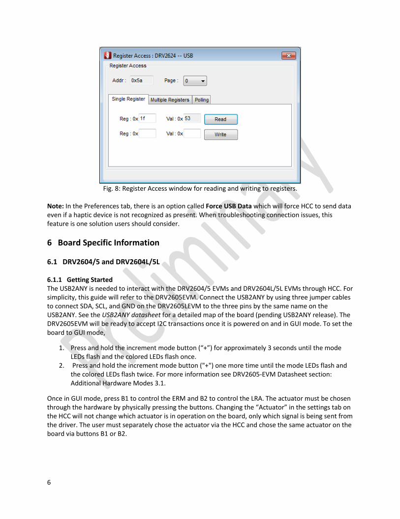
Besides the Register Map, the user has direct control over the registers through the Register Access window (shown below in Fig. 8) when a board is connected. Users can perform single or multi-byte writes and reads. There is also an option to poll the I2C to constantly monitor the communication lines. Finally, the log is a useful tool for users who are experiencing difficulties. It will show errors for improper connections and other errors, such as when the user selects the “Ethernet” button when no Ethernet cable is attached. When something is not functioning correctly, the user should check the log for more information.
6
Fig. 8: Register Access window for reading and writing to registers.
Note: In the Preferences tab, there is an option called Force USB Data which will force HCC to send data even if a haptic device is not recognized as present. When troubleshooting connection issues, this feature is one solution users should consider.
6 Board Specific Information
6.1 DRV2604/5 and DRV2604L/5L 6.1.1 Getting Started The USB2ANY is needed to interact with the DRV2604/5 EVMs and DRV2604L/5L EVMs through HCC. For simplicity, this guide will refer to the DRV2605EVM. Connect the USB2ANY by using three jumper cables to connect SDA, SCL, and GND on the DRV2605LEVM to the three pins by the same name on the USB2ANY. See the USB2ANY datasheet for a detailed map of the board (pending USB2ANY release). The DRV2605EVM will be ready to accept I2C transactions once it is powered on and in GUI mode. To set the board to GUI mode,
1. Press and hold the increment mode button (“+”) for approximately 3 seconds until the mode LEDs flash and the colored LEDs flash once.
2. Press and hold the increment mode button ("+") one more time until the mode LEDs flash and the colored LEDs flash twice. For more information see DRV2605-EVM Datasheet section: Additional Hardware Modes 3.1.
Once in GUI mode, press B1 to control the ERM and B2 to control the LRA. The actuator must be chosen through the hardware by physically pressing the buttons. Changing the “Actuator” in the settings tab on the HCC will not change which actuator is in operation on the board, only which signal is being sent from the driver. The user must separately chose the actuator via the HCC and chose the same actuator on the board via buttons B1 or B2.
7
6.1.2 Console Window Overview The console window is divided into two sections, Settings and Work Mode. The Settings section contains four tabs, Actuator, Voltage, Calibration, and Advanced, that are used to set the registers of the DRV260x device. The Work Mode section has a drop down menu containing the different types of trigger modes, PWM input, Analog input, Real Time Playback, Diagnostics, Actuator Life Test, and Audio to Haptics (for DRV2605/05L only). The user should first input the settings according to the actuator being driven and then choose the appropriate work mode. 6.1.2.1 Console Window – Settings Section In the Actuator tab, the user can choose whether they want to drive an ERM (eccentric rotating mass) or an LRA (linear resonant actuator) by selecting the “actuator” tab and choosing accordingly. From here, they can select closed or open loop to run the device with or without the auto-resonance frequency tracking. The DRV2605/5L have a selection of 6 ERM and 1 LRA libraries for the user to choose from in the “Library” drop-down tab. For LRA mode, you should also enter the resonance frequency of the LRA being driven. This frequency is used in the calculation for Rated Voltage and DRIVE_TIME. In the Voltage tab, the user can adjust rated voltage (full-scale output during closed-loop) and the overdrive voltage (maximum voltage allowed to actuator). In open loop the output voltage is determined by the overdrive Voltage. The corresponding register addresses and values are also shown. The Calibration tab is used to calibrate the ERM or LRA being tested. The result of the calibration will appear letting the user know if the calibration was successful or failed. In the event of failing calibration make sure the ERM and LRA parameters are correct and the actuator is attached to a stable mechanical ground. If the calibration still fails move to the Advanced tab and refer to the datasheet. The Advanced tab contains advanced settings used for calibrating the actuator. The DRIVE_TIME should be set appropriately based on the LRA frequency or the frequency in which the user wants to sample the ERM’s BEMF voltage. The DRIVE_TIME is one half of the period of the LRA’s resonance frequency. The DRV26xx device used this DRIVE_TIME as an initial guess of the LRA frequency as the auto-resonance tracking algorithm begins. BLANKING and IDISS are described in the datasheet. The ZC_DET_TIME only appears in the DRV2604L/5L console window and represents the minimum length of time devoted for detecting a zero crossing. For a more detailed explanation of the registers used in the Actuator, Voltage, Calibration, and Advanced tabs, the user should utilize the Register Map (Tools -> Register Map -> DRV260X) or the datasheet. 6.1.2.1 Console Window – Work Mode Section Within the Work Mode section, the user has several options according to how they wish to control the actuator. For the DRV2605/5L, the internal libraries are available for use in the first three tabs (Internal Trigger, External Edge Trigger, and External Level Trigger). The DRV2604/4L contain RAM for the user to load their own custom waveforms (through the RAM Manager) while the DRV2605/5L have ROM that contains the Licensed Immersion™ Touchsense® waveform library. The first three tabs are not usable for the user with the DRV2604/4L until they upload waveforms onto the board. To control the actuator using an outside waveform, select External PWM or External Analog accordingly and then reference Section 4 of the DRV260XXEVM-CT datasheet for information on how to connect the hardware.

8
Real Time Playback gives the user direct control over the chosen actuator. Remember, the user must have the same actuator chosen on the board (B1 for ERM, B2 for LRA) and on the HCC in the Actuator tab. The Diagnostic mode will run diagnostics and show the results for success of fail. The Actuator Life Test mode give users the ability to run long lifetime tests with specified ON and OFF times. Enter the desired times to be tested and then the number of cycles to test. The last mode, Audio to Haptics, shows the settings for the Audio to Haptics function. Refer to the datasheet for explanations of these settings.
6.2 DRV2605LEVM-MD 6.2.1 Getting Started The DRV2605LEVM-MD is capable of directly connecting to the HCC GUI without external I2C control and therefore does not need the USB2ANY. First, connect the DRV2605LEVM-MD to the PC USB port. Next, the user switch must be pressed. When the user switch is pressed, the board goes to USB communication mode, which disables the capacitive touch buttons. A power cycle or software reset is required to go back to capacitive-touch mode. The user switch is a pushbutton labelled “USER SW” and LED1 turns on to indicate that the firmware is active for USB transactions. After selecting the user switch and ensuring the LED1 light is on, open up the HCC and select “0.TI-Haptics DRV2605LEVM-MD” and then “Connect” in the dropdown window next to USB.
Fig. 9: The HCC after the DRV2605LEVM-MD is connected to the PC.
After connecting, the DRV2605LEVM-MD console window will automatically appear. If properly connected, the console window will have the title “Console: DRV2605LEVM-MD – USB.” If the DRV2605L console window appears instead of the DRV2605LEVM-MD, then the board needs a firmware update to communicate properly with the HCC. To perform a firmware update, go to Help->Firmware Update and then follow the instructions listed at the bottom of the window and try the process again. 6.2.2 Console Window: Driver and Settings In the console window, there are two main tabs: Driver and Settings. Within the Settings tab, the user can properly initialize the board for use with the actuators and run Auto Calibration to ensure optimum performance. Settings can also be imported and exported in the Settings tab. In the Driver tab, there are two modes: Effect Sequence Playback and Real Time Playback (RTP). In Effect Sequencer mode, the user can set different waveform sequences to different actuators, and then trigger all the actuator to vibrate with one click. In RTP mode, all the actuators will vibrate at the same amplitude with one click.

9
6.3 DRV2624/5 6.3.1 Getting Started To control the board with HCC, the user must first plug in the board and then set it to GUI mode. For the DRV2624/5EVM-CT, set the board to GUI mode by holding down the (+) button for approximately 3 seconds. The LEDs will flash and then the right half of the LEDs will remain on to indicate the board is in GUI mode. Once the user plugs in the device, the name of the driver will appear next to USB (shown below in Fig. 10). The user must then select “Connect” in order to begin programming the device. At the bottom of the screen, the connection to the device is monitored. If using the DRV262XEVM-mini, please connect the NRST pin to VDD or a GPIO because the HCC does not control the NRST pin. Also, connect the SDA, SCL, and GND lines to the USB2ANY (required for the mini-board). If the HCC recognizes the USB-COM but not the DRV262XEVM-mini, try using the console window simulator and forcing the USB communication (Tools -> Preferences -> Force USB Data). The DRV262X must be externally powered to receive I2C commands.
Fig. 10: The HCC window once the board is plugged in via USB.
Note: at the top left of the console window, after DVRXXXX, it must say “USB.” If instead it says “Simulator,” then the board is not fully connected and the user will not be able to program the device. If it does not read properly the first time, try removing the USB from the computer, restarting HCC, and connecting again. 6.3.2 Overview of Console Window The DRV2624 and DRV2625 have the same console window layout. The console is divided into three sections. The initialization section is divided into four tabs – Actuator, Voltage, Interrupt, and Advance. This section is used to change the actuator settings. The work mode section is used to start and stop different processes available for driving actuators. The final section contains reset buttons, NRST high/low, and a pulse trigger button. 6.3.2.1 Initialization – Actuator Within the Actuator tab, the user can select the settings at which they would like to operate their chosen haptic actuator. By selecting “Open Loop” instead of “Closed Loop,” the user bypasses the auto-resonance tracking and can manually set the frequency. The TRIG PIN FUNC refers to the type of trigger used to start all processes (RTP, Waveform Sequencer, Calibration and Diagnostics). The trigger can be controlled by software using the GO bit (internal trigger), or by hardware using the TRIG/INTZ pin (external trigger pulse or level). For more information, refer to the DRV2624/5 datasheet. The AUTO BRK OL box will enable auto-braking out of open loop operation. The AUTO BRK INTO STBY will enable braking when the part is put into standby. The user cannot select the Voltage, Interrupt, or Advance tabs until a frequency value is input.

10
6.3.2.2 Initialization – Voltage Within the voltage tab, the user can adjust rated voltage (full-scale output during closed-loop) and the overdrive voltage (maximum voltage allowed to actuator). In open loop the output voltage is determined by the overdrive Voltage. The corresponding register names, values, and addresses are also shown.
Fig 11. Initialization – Voltage Tab
6.3.2.3 Initialization – Interrupt The Interrupt tab contains five different interrupt notifications. The details of each type of notification can be found in the register map with the name of the register as shown in figure 12. The register map window may need to be enlarged to reveal the search bar. More information can be found in the device datasheet.
Fig. 12: Result from searching “OC_DETECT” in the Register Map.
6.3.2.4 Initialization – Advanced The final tab in the Initialization section gives the user advanced control over the actuator. Some actuators may require fine-tuning for proper auto-calibration. The specifics of each parameter can be found by looking up the register in the register map or referring to the datasheet.

11
Fig. 13: Advance tab that gives the user more control over the actuator.
6.3.3 Work Mode - Overview Within the Work Mode section, there are several options: Real Time Playback, Waveform Sequence, Diagnostic, AutoCalibration, and Actuator Life Test. Users should fill out the Initialization section before moving to the work mode section. Next, users should use the auto-calibration mode. 6.3.3.1 Work Mode – Auto-Calibration Before testing the device, the user should run auto-calibration. The auto-calibration routine expects the actuator to have reached a steady acceleration before the calibration factors are calculated. Because the start-time characteristic can be different for each actuator, the AUTO_CAL_TIME parameter can change the duration of the automatic level-calibration routine to optimize calibration performance. The BEMF_GAIN parameter sets the analog gain for the back-EMF amplifier. The auto-calibration routine automatically populates the BEMF_GAIN bit with the most appropriate value for the actuator. 6.3.3.2 Work Mode – Real Time Playback After adjusting the settings, Real Time Playback allows the user to proportionally control the actuator. The user can adjust the playback strength of the actuator by moving the sliding bar and the value is stored in the RTP_INPUT register. If an LRA is operating in closed loop mode, the “Report Freq” box shows the resonant frequency. The user can observe the usefulness of Auto-Resonance Detection by operating a LRA in open loop mode at a frequency different than the resonant frequency and observing the drop in performance. 6.3.3.3 Work Mode – Waveform Sequence For devices with internal ROM such as the DRV2625, the Waveform Sequence tab gives the user control over the waveforms available in the libraries from Immersion. The DRV2624 contains 1 kB of integrated RAM for custom waveforms instead of the library, so the DRV2625 is shown below instead of the DRV2624. For the drivers with RAM such as the DRV2624, the Waveform Sequence tab will not be usable until the user loads waveforms onto the board using the RAM Manager (Tools->RAM Manager-> DRVXXXX).

12
Fig. 14: Waveform Sequence utilized by the DRV2625.
As shown in Figure 14, the user can select from 123 waveforms using the drop down menu to navigate the waveforms and can repeat the waveform up to three times per sequence. Additionally, the user can include a delay into their sequence by selecting the Delay box, and can use the slide bar to set a delay from 0 to 1270ms. There are also several other controls such as play interval, scaling, and main repeat (repeats the entire sequence) to provide ease of use and control. 6.3.3.4 Work Mode – Diagnostic In the Diagnostic tab, the user can determine the actuator impedance. The DRV2624/5 device is capable of determining whether the actuator is not present (open) or shorted. If a fault is detected during the diagnostic process, the DIAG_RESULT bit is asserted. The DRV2624/5 device also features actuator resistance measurement, which is available in the DIAG_Z_RESULT parameter. More information is available in the DRV2624/5 data sheet. 6.3.3.5 Work Mode – Actuator Life Test The final option in Work Mode, the Actuator Life Test, lets the user run the actuator for a number of cycles to observe the performance over time. 6.3.4 Board Status and Pulse Trigger The DRV2624/5 device has an automatic go-to-standby state and a battery preservation function to help reduce power consumption without user intervention. The NRST pin allows for a full shutdown state for additional power savings and the user can set it HIGH or LOW. In order to utilize the Pulse Trigger

13
button, the user must set the TRIG_PIN_FUNC to 0 (Ext-pulse Trigger) within the Actuator tab of the Initialization section.
6.4 DRV2667 6.4.1 Getting Started A USB2ANY is needed to connect the DRV2667 to the computer. Connect the USB2ANY by using three jumper cables to connect SDA, SCL, and GND on the DRV2605LEVM to the three pins by the same name on the USB2ANY. See the USB2ANY datasheet for a detailed map of the board (pending USB2ANY release). The DRV2667EVM will be ready to accept I2C transactions once it is powered on. The DVR2667EVM does not need to be in GUI mode to communicate with the HCC over the USB2ANY through I2C. See External I2C Input on the DRV2667EVM for more information. After connecting the USB2ANY to the DRV2667EVM and both boards to the computer, the user must press Connect to begin controlling their device through the GUI. 6.4.2 Overview of Console Window After connecting to the DRV2667EVM, the console window will appear. The console window is divided into two sections, settings and work mode. In the settings section, the user can adjust the gain, which adjusts the output voltage from the driver that goes into the Piezo. A breakdown of the gain is shown below:
28.8 dB, 50 Vpp
34.8 dB, 100 Vpp
38.4 dB, 150 Vpp
40.7 dB, 200 Vpp
Refer to the datasheet (DRV2667EVM-CT section 3.6.1) to adjust these settings via software or hardware. Within work mode, there are three options: Internal trigger, External Analog, and FIFO Playback. In order to operate the Internal Trigger RAM mode, the user must upload waveforms using the RAM Manager. In External Analog mode, waveforms must be input into the device. In FIFO Playback mode, the user can control the actuator by adjusting the settings and selecting Start.
6.4.2.1 Work Mode – Internal Trigger: Uploading Waveforms To upload waveforms through the RAM Manager, the user must go to Tools -> RAM Manager -> DRV2667. Here the user can load waveforms from binary files (.bin) by selecting Import and then Write RAM. The user can create custom waveforms for non-commercial use through the WaveSynthesizer (shown below) by selecting Advanced in the DRV2667 RAM Manager.

14
Fig. 15: WaveSynthesizer for the DRV2667.
The user can create waveforms by adjusting the frequency, amplitude, duration, and number of times the waveform will repeat and then selecting Create. For haptic applications of piezos, the frequency of the waveforms is generally 100 – 200 Hz. Higher frequency waveforms may emit audible noise. Once created, the waveform will appear in the Waveforms block with the name “Effect 1”. Subsequent waveforms will be named Effect 2, Effect 3, etc. The most recently created waveform will appear in the graph at the bottom. After creating the desired waveforms, selecting Write RAM will make the created waveforms selectable in the DRV2667 console window.

15
Fig. 16: Selecting the waveforms after creating them via the WaveSynthesizer.
Alternatively, the waveforms could be controlled from the WaveSynthesizer window via the Waveform Sequencer block. The user must move the waveforms from the Waveform block to the Waveform Sequencer block by selecting the name of the waveform and clicking the appropriate arrow. To play the waveforms on the attached piezo, select Start Waveforms.
6.4.2.2 Work Mode – External Analog In External Analog mode, waveforms must be input into the device. Section 3.5 of the DRV2667EVM-CT datasheet is referenced below for more information:
Fig. 17: External Analog/PWM Input
The DRV2667EVM-CT accepts analog or PWM inputs for the analog IN+/IN- pins of the DRV2667. To use the IN+/IN- pins of the DRV2667 follow the instructions below:
1. Enter Design & Test Modes. Select Mode 7 (00111’b) using the increment mode button (“+”). 2. Select the gain and voltage using buttons B1–B4:

16
• B1 – 28.8 dB, 50 Vpp • B2 – 34.8 dB, 100 Vpp • B3 – 38.4 dB, 150 Vpp • B4 – 40.7 dB, 200 Vpp
3. Turn on the signal source to begin output. 6.4.2.3 Work Mode – FIFO Playback For immediate control of the piezo, FIFO Playback mode outputs a 200 Hz sine wave or a custom waveform to the piezo. The duration can be adjusted from 5 – 20m
6.5 DRV2510/1 6.5.1 Getting Started The user must plug the DRV2510/1EVM into the computer via micro USB. After “0.TI DRV251XQ1 EVM” appears in the toolbar next to USB, select Connect. The console window should appear with the title “Console: DRV251XEVM – USB.” If instead of USB it says Simulator, then the board is not connected correctly. In addition to the USB, the DRV251XEVM must receive a separate power source for the driver. VDD is provided through jumper J5 on the. The user can now connect the solenoid or voice coil and operate it through HCC. Note: If initially on, the user must toggle “Enable” off and then back on the first time in order for the DRV to respond. 6.5.2 Console Overview The console window is divided into two tabs: Standard Drive and WaveBuilder. Within Standard Drive, the user can control the PWM input frequency and voltage percentage (duty cycle). The frequency can be adjusted for better resolution. Since solenoids don’t see high frequencies, you can also keep the PWM frequency at 32kHz and create a square wave output by using the different types of PWM Playback. The PWM Playback can be changed by clicking on the “Continuous” button at the bottom of the window. The three different modes are Continuous, Pulse, and Single output. If operating in Continuous mode, the user can adjust the frequency down around 200 Hz for best performance with solenoids. The Single and Pulse modes should use a higher PWM frequency with setting that will create an output at the desired frequency. The recommended range for most solenoids is less than 200 Hz. Click the black box in order to enable and disable the output. Note: To change the PWM Input Frequency, the user must press the “enter” key on their keyboard for the HCC to recognize the new frequency. If the user enters a new frequency without pressing enter, the old frequency will be played. The WaveBuilder tab allows users to create custom waveforms for evaluation purposes. The output PWM frequency is set at 32 kHz allowing high resolution. The control buttons do the following: Clear Plot will erease any data in the plot; Add Many Points from Text Box will load the points into the plot; Add Single Point will append the point in the box directly below the button to the plot; Start Waveform enables the output; Triangle, Sine, and Impulse will append preset waveforms to the plot area when clicked. Be careful when adding points to the graph because you cannot delete single points, you can only clear the whole plot. Time Between Steps sets the time each point will last at that magnitude. Users can also select the number of times to repeat the output or set an infinite loop. Lastly, the large box in the middle can be filled with points separated by commas to build the desired evaluation waveform.

17
In the status section of the DRV2510, there is a grid of eight different boxes labeled “Active, HiZ, Diag Active…” and the user can find more information about each one by searching “STA” in the DRV2510 Register Map. If a fault is triggered, it will turn red on the console window. The DRV2511 does not have diagnostic reporting.