hardware description p2300hw-en - software.apextoolgroup.com · the software that is used is not...
TRANSCRIPT

For additional product information visit our website at http://www.ClecoTools.com
Hardware descriptionP2300HW-EN
2018-01
mPro400GCD-PGlobal Nutrunner Controller Primary

2
P2300HW-EN2018-01
Copyright © Apex Tool Group, 2017
No part of this document may be reproduced in any way or in any form, in whole or in part, or in a natural or machine-readable language, or transmitted on electronic, mechanical, optical, or other media, without the express permission of the Apex Tool Group.
DisclaimerApex Tool Group reserves the right to modify, supplement, or improve this document or the product without prior notice.
TrademarkCleco is a trademark of the Apex Tool Group Division.
Apex Tool Group GmbHIndustriestraße 173463 WesthausenGermanyPhone: +49 (0) 73 63 81 0Fax: +49 (0) 73 63 81 222

Contents
P2300HW-EN2018-01
3
1 Notes on this Hardware-Description 4
2 Safety 42.1 General requirements.................................................................................................. 42.2 Warnings and notes..................................................................................................... 52.3 System-relevant safety instructions............................................................................. 6
3 Technical specifications 8
4 Pin assignment 9
5 Storage access 12
6 Items delivered 12
7 Installation 137.1 Location considerations............................................................................................. 137.2 Mounting.................................................................................................................... 13
8 Prior to initial operation 148.1 Series 30/50EAN....................................................................................................... 148.2 Series 18/48EAE ....................................................................................................... 158.3 Connecting the controller to the power source.......................................................... 16
9 System 17
10 Connections 18
11 Dimensions 19

P2300HW-EN2018-01
1 Notes on this Hardware-Description
The original language of this description is German.This description is intended for all persons who connect and install the controller. The software that is used is not the subject of this description.
You can find further documents
Symbols in the text
2 Safety
2.1 General requirements Only operate the controller after you have read this and
fully understood this document. Failure to follow the directions and safety instructions could result in electric shocks, burns and/or serious injuries.
Keep this document in a safe place for future use! These safety instructions must be accessible to the operator at all times. They must be presented and made accessible to all persons using or repairing the device.
Intended useThe product is a part of the Cleco Production Tools tighten-ing system and is intended exclusively for industrial use in fastening processes. Only use the nutrunner controller under the following conditions:• in conjunction with the components listed in the EC
Declaration of Conformity P3268C. • under the prescribed environmental conditions; see the
relevant documentation• with the permissible supply voltage• within the power range, which is specified in the techni-
cal data• in EMC Limit Class A (electromagnetic immunity for
industrial areas). For the currently observed EMC stan-dards, see the EC Declaration of Conformity.
Do not use the nutrunner controller:• in potentially explosive areas• in damp spaces/outdoors• in connection with cutting tools (drills, milling cutters,
grinders…)
No. Document type
P2279SB System handbook
Italic Denotes menu options, e.g.,Diagnostics
> Denotes the selection of a menu option from a menu, e.g., File > Print
<…> Denotes switches, pushbuttons or the keys of an external keyboard, e.g., <F5>
Courier Denotes input fields, check boxes, radio but-tons or dropdown menus.Denotes filenames and paths, e.g., setup.exe
/ Acts as a separator for the subdirectories in a file path, e.g., File/Print (operating system OS9)
• Denotes lists
Denotes instructions that must be followed
4

P2300HW-EN
Operator trainingThe tightening system may only be put into operation, adjusted and tested by qualified and trained personnel. The personnel must be instructed by qualified employees1) of Apex Tool Group. The nutrunner controller has been preset by Apex Tool Group. The adjustment of the nutrunner control-ler to special requirements may only be carried out by a qualified person1).Additional information can be found in the Programming Manual.
Personal protective equipment (PPE)Risk of injury by being wound up in and caught by machin-ery When working with rotating parts, it is not permitted to
wear gloves. Recommendation: Freely rotating u-GUARD protected fastening tools from APEX.
Wear close-fitting clothing. Wear safety shoes. If necessary, wear a hairnet.Risk of injury due to parts being ejected. Wear protective goggles.
2.2 Warnings and notesWarning notes are identified by a signal word and a picto-gram:• The signal word describes the severity and the proba-
bility of the impending danger.• The pictogram describes the type of danger.
Symbols on the productBe sure that you understand their meaning before operation
1. Due to their vocational training, knowledge, expe-rience and understanding of the circumstances involved in this kind of work, suitably qualified per-sonnel are able to identify potential hazards and to initiate appropriate safety measures. Qualified per-sonnel are obliged to comply with regulations.
CAUTION! A symbol combined with the word CAU-TION indicates a hazard with a low level of risk which, if not avoided, could result in minor or moderate injuries or environmental damage.
DANGER! A symbol combined with the word DAN-GER indicates a hazard with a high level of risk which, if not avoided, will result in death or serious injury.
WARNING!A symbol combined with the word WARN-ING indicates a hazard with a medium level of risk which, if not avoided, could result in death or serious injury.
This sign warns of a possibly damaging sit-uation.Failure to observe this note may cause the product or parts thereof to be damaged.
General notes include application tips and useful informa-tion but no hazard warnings.
Electrical voltage
WARNING Disconnect mains before opening.
CE compliantThe product corresponds to the prescribed technical requirements in Europe.
Read all instructions.
ATTENTION!
5
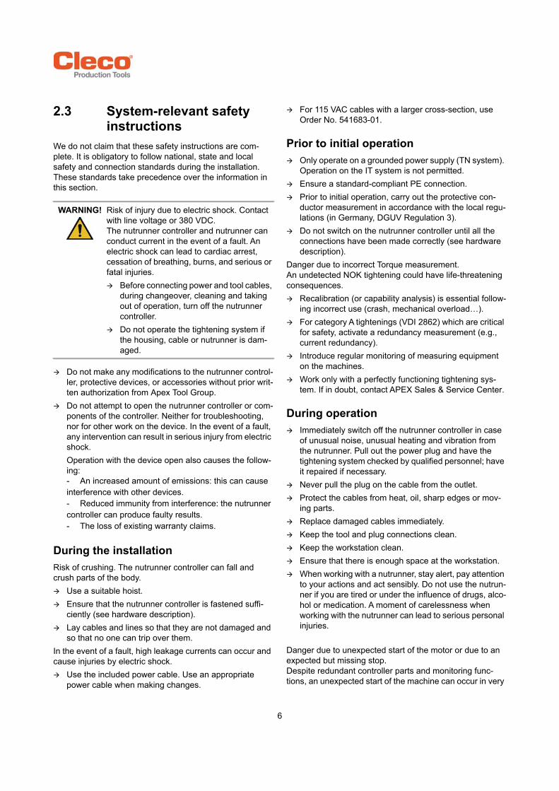
2.3 System-relevant safety instructions
We do not claim that these safety instructions are com-plete. It is obligatory to follow national, state and local safety and connection standards during the installation. These standards take precedence over the information in this section.
Do not make any modifications to the nutrunner control-ler, protective devices, or accessories without prior writ-ten authorization from Apex Tool Group.
Do not attempt to open the nutrunner controller or com-ponents of the controller. Neither for troubleshooting, nor for other work on the device. In the event of a fault, any intervention can result in serious injury from electric shock. Operation with the device open also causes the follow-ing:- An increased amount of emissions: this can cause interference with other devices.- Reduced immunity from interference: the nutrunner controller can produce faulty results.- The loss of existing warranty claims.
During the installationRisk of crushing. The nutrunner controller can fall and crush parts of the body. Use a suitable hoist. Ensure that the nutrunner controller is fastened suffi-
ciently (see hardware description). Lay cables and lines so that they are not damaged and
so that no one can trip over them.In the event of a fault, high leakage currents can occur and cause injuries by electric shock. Use the included power cable. Use an appropriate
power cable when making changes.
For 115 VAC cables with a larger cross-section, use Order No. 541683-01.
Prior to initial operation Only operate on a grounded power supply (TN system).
Operation on the IT system is not permitted. Ensure a standard-compliant PE connection. Prior to initial operation, carry out the protective con-
ductor measurement in accordance with the local regu-lations (in Germany, DGUV Regulation 3).
Do not switch on the nutrunner controller until all the connections have been made correctly (see hardware description).
Danger due to incorrect Torque measurement.An undetected NOK tightening could have life-threatening consequences. Recalibration (or capability analysis) is essential follow-
ing incorrect use (crash, mechanical overload…). For category A tightenings (VDI 2862) which are critical
for safety, activate a redundancy measurement (e.g., current redundancy).
Introduce regular monitoring of measuring equipment on the machines.
Work only with a perfectly functioning tightening sys-tem. If in doubt, contact APEX Sales & Service Center.
During operation Immediately switch off the nutrunner controller in case
of unusual noise, unusual heating and vibration from the nutrunner. Pull out the power plug and have the tightening system checked by qualified personnel; have it repaired if necessary.
Never pull the plug on the cable from the outlet. Protect the cables from heat, oil, sharp edges or mov-
ing parts. Replace damaged cables immediately. Keep the tool and plug connections clean. Keep the workstation clean. Ensure that there is enough space at the workstation. When working with a nutrunner, stay alert, pay attention
to your actions and act sensibly. Do not use the nutrun-ner if you are tired or under the influence of drugs, alco-hol or medication. A moment of carelessness when working with the nutrunner can lead to serious personal injuries.
Danger due to unexpected start of the motor or due to an expected but missing stop.Despite redundant controller parts and monitoring func-tions, an unexpected start of the machine can occur in very
WARNING! Risk of injury due to electric shock. Contact with line voltage or 380 VDC.The nutrunner controller and nutrunner can conduct current in the event of a fault. An electric shock can lead to cardiac arrest, cessation of breathing, burns, and serious or fatal injuries. Before connecting power and tool cables,
during changeover, cleaning and taking out of operation, turn off the nutrunner controller.
Do not operate the tightening system if the housing, cable or nutrunner is dam-aged.
6

rare cases. Possible reasons: Remote control of diagnostic functions, bit dump in the memory of the controller.Mechanical hazards such as jars/jolts due to counter torques; risk of injury due to winding up and seizing can result from the nutrunner. Use the tool at the designated grip points. Use prescribed counter torque absorbers. For torques,
see Instruction manual tool. After switching on the nutrunner controller, wait until the
boot cycle is completed. This usually takes about 60 sec. Only then switch off / on again.
During maintenance Consider local regulations for maintenance and servic-
ing for all operating phases of the tightening system. The nutrunner control is generally maintenance-free.
When cleaning Only clean the tool and the nutrunner controller from
the outside with a damp cloth. Do not immerse the tool and nutrunner controller in
water or cleaning agents. Do not use a high pressure cleaner.
At the repair Send the complete nutrunner controller for repair to
your Sales & Service Center.
At disposalComponents of the tightening system present risks to health and the environment. The tightening system con-tains components that can be recycled, as well as compo-nents that have to be disposed of specifically. Follow the locally applicable regulations. Separate the components and dispose of them by seg-
regating them clearly. Collect auxiliary materials (oils, greases) when draining
and dispose of them properly. Separate the components of the packaging and dis-
pose of them unmixed. Hand in the nutrunner and the defective nutrunner con-
troller at your company collection point or return to the Sales & Service Center.
Observe generally valid disposal guidelines such as, in Germany, the Electrical and Elec-tronic Equipment Act (ElektroG) and the Bat-tery Act (BattG): Used up batteries must be disposed of.
Hand in the batteries at your company collection point or return to the Sales & Service Center.
7

8
P2300HW-EN2018-01
3 Technical specificationsAmbient conditions
Power supply
System data
Weight
Features DataOperation site IndoorsAmbient temperature 0...45 °C1)
Storage temperature -20...70 °CType of cooling Convection (self-cooling)Relative humidity 10 – 90%, no condensationWorking height Up to 2000 m (6,561.7 ft) above sea level1)
1) Note the derating. See system handbook
Protection Class DIN EN 60529 IP42Degree of contamination EN 61010 2Transient overvoltage EN 61010 CAT Shock max. DIN EN 60068-2-27 15 GVibration max. DIN EN 60068-2-5 59.6–160 Hz: 2 G
Features DataSupply voltage, single-phase 100–240 VAC ±10%Rated supply current 1–2 AFrequency 50/60 HzPeak current 16 ARated power 1600 VA max.Idling 160 VA
Features DataSystem functions Battery buffered RealTimeClock, buffer time: 20 years (at 20 °C)Display LC display with touchscreen, 10.4" TFT liquid crystal display,
resolution 800 x 600, connection to Panel & Touch possibleOperating system OS-9000, real-time operating system, bootable without mechanically
moving drives, no UPS requiredHMI (Human-Machine Interface) Virtual keyboard for alphanumeric inputs
Model Weightlb kg
mPro400GC-P 30.2 13.7

P2300HW-EN2018-01
4 Pin assignmentAll connections are short-circuit proof.
X5, X6 – Serial port for additional devices• All outputs provide RS232 conforming signals.• The inputs allow voltages in the range from -15 V to
+15 V.- Voltages < 0.8 V correspond to a zero.- Voltages > 2.4 V are interpreted as a one.- Open inputs are preset to zero using a pulldown
resistor.• The power supply pins are connected directly to the
main board power supply.
X7, X8 – Anybus CCOptional slots for Anybus CC modules,
X21 – TSnet system busInterface port for TSnet cable.
X22 – ARCNET system busThe station controller has an integrated bus termination; therefore, no external termination is necessary.
X23 – Supply
X24 – Tool cable 30/50EAN Series
X25 – Tool cable 18/48EAE Series
Do not connect or disconnect any device during operation. Doing so may result in a system reset.
Pin RS232-1 X5
RS23-2 X6
9 pin D-Sub malewith screw lock
1 – –2 RxD RxD 3 TxD TxD 4 – –5 GND GND 6 – –7 RTS RTS 8 CTS CTS 9 – –
Pin Signal 8 pin M12 circular connectorX-coded
1 Tx +2 Tx -3 Rx +4 RX -5 0 VDC6 0 VDC7 +24 VDC8 +24 VDC
ATTENTION!
5
6
7
81
2
3
4
Pin Signal 8 pin M12 circular connectorA-coded
1 N.C.2 DATA-B3 GND4 +5 VDC5 DATA-A6 N.C.7 0 VDC8 +24 VDC
Description IEC connector C14Connector with fuse holder 2-pin, 5 × 20 mm, 16 A slow-blow
Use plug locking mechanism. See 6.3, "Connecting the controller to the power source", Page 29.
Pin Signal M23 circular connector1-3 Power4 PE (functional ground)5 Tool bus
Pin Signal ECTA circular connectorPush-pull
1-3 Power4 PE5 Signals
Output (Sockel)
6
7
82
3
45
1
ATTEN-TION!
12
3
4
5
5
1 2
3
4
9

P2300HW-EN2018-01
X9, X10 – Input/OutputThe required signal circuits are connected to these input/output connectors. The signal groups are not gal-vanically connected to the power supply; galvanic isolation is required.• 16 digital inputs/outputs, optically isolated for 24 V level/0.5 A• 8 inputs/8 outputs/2 +24 VDC/2 GND• Output current: 500 mA per output, 2000 mA total
Connectors that use an internal 24 V power supply(Primary, Master)Inputs• Internal 24 V power supply for the controller.• Pin 11 and 23 (common GND) serve as a "return line" for the outputs.• Pin 11 and 23 must be connected to Pin 12 or 24 with jumpers.
Outputs• Internal 24 V power supply for the controller• Pin 2 and 14 (common output) are the voltage source for the inputs.• Pin 2 and 14 must be connected to Pin 1 or 13.
A single device must not require a current of more than 500 mA. The current monitor switches off the output in the event of an overcurrent.
Pin Signal X9 Pin Signal X10 2x12 pin Phoenix MCD 0.5/24-G1-2.5 Order No. S981211
12 GND-int 24 GND-int11 GND I/O0–3 23 GND I/O4–710 Output O3 22 Output O79 Output O2 21 Output O68 Output O1 20 Output O57 Output O0 19 Output O46 Input I3 18 Input I75 Input I2 17 Input I64 Input I1 16 Input I53 Input I0 15 Input I42 +24 VDC A0–A3 14 +24 VDC A4–A71 +24 VDC-int 13 +24 VDC-int
Mating connectorPhoenix FK-MC 0.5/12-STZ3-2.5
Order No. S981211
ATTEN-TION!
X9 X10
10

P2300HW-EN2018-01
Connectors that use an external 24 V power supply(Primary, Master)Inputs• External 24 V power supply for the con-
troller.• Pin 11 and 23 (common GND) serve as a
"return line" for the outputs.• The GND for the external 24 V power
supply must be used as the return line for Pin 11 and 23.
Outputs• External 24 V power supply for the con-
troller.• Pin 2 and 14 (common output) are the
voltage source for the inputs.• Pin 2 and 14 must be connected to the
external 24 V power supply.
Signal X9 Signal X10Pin I/O Name Pin I/O Name12 Off GND2 24 Off GND211 On Common GND 23 On Common GND10 Output O3 22 Output O79 Output O2 21 Output O68 Output O1 20 Output O57 Output O0 (linking OK), e.g. 19 Output O46 Input I3 (tool start), e.g. 18 Input I75 Input I2 17 Input I64 Input I1 16 Input I53 Input I0 15 Input I42 On Output O0-O3 common 14 On Output O4-O7 common1 Off +24 V2 13 Off +24 V2
Signal X9 Signal X10Pin I/O Name Pin I/O Name12 Off GND2 24 Off GND211 On Common GND 23 On Common GND10 Output O3 22 Output O79 Output O2 21 Output O68 Output O1 20 Output O57 Output O0 (linking OK), e.g. 19 Output O46 Input I3 (tool start), e.g. 18 Input I75 Input I2 17 Input I64 Input I1 16 Input I53 Input I0 15 Input I42 On Output O0-O3 common 14 On Output O4-O7 common1 Off +24 V2 13 Off +24 V2
+ -
11
P2300HW-EN2018-01
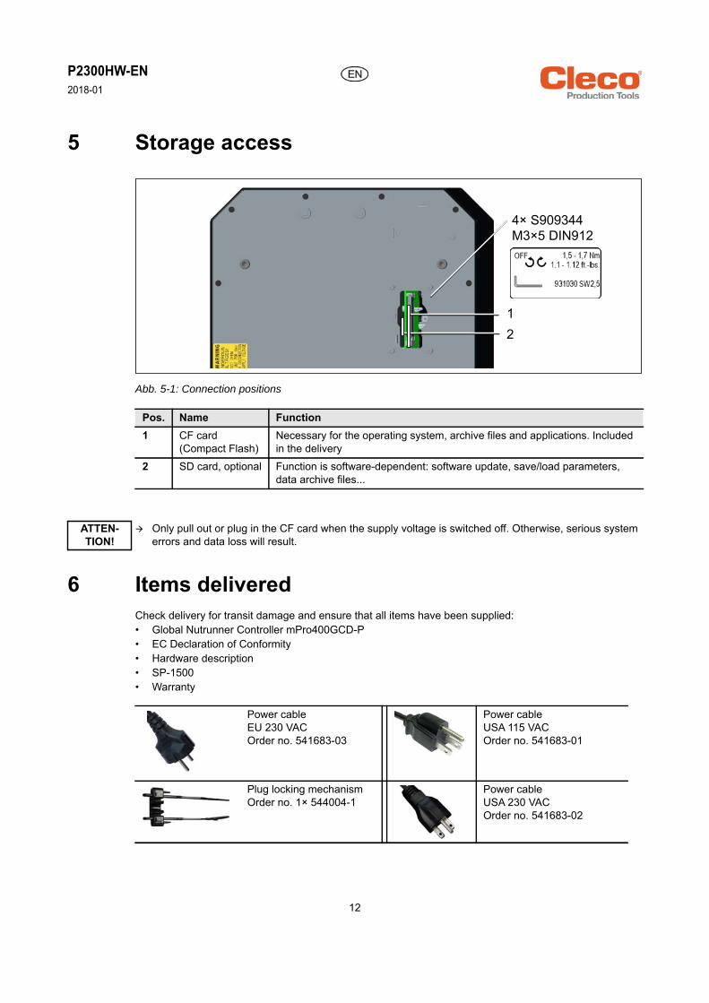
5 Storage access
Abb. 5-1: Connection positions
6 Items deliveredCheck delivery for transit damage and ensure that all items have been supplied:• Global Nutrunner Controller mPro400GCD-P• EC Declaration of Conformity• Hardware description• SP-1500• Warranty
Pos. Name Function1 CF card
(Compact Flash)Necessary for the operating system, archive files and applications. Included in the delivery
2 SD card, optional Function is software-dependent: software update, save/load parameters, data archive files...
Only pull out or plug in the CF card when the supply voltage is switched off. Otherwise, serious system errors and data loss will result.
Power cableEU 230 VACOrder no. 541683-03
Power cableUSA 115 VACOrder no. 541683-01
Plug locking mechanismOrder no. 1× 544004-1
Power cableUSA 230 VACOrder no. 541683-02
21
4× S909344M3×5 DIN912
ATTEN-TION!
12

P2300HW-EN2018-01
7 InstallationSoftware is already installed on the controller. The minimum settings for your bolt connections must be car-ried out by a qualified person with the controller or a PC in order to start fastening work.
7.1 Location considerations Each controller is mainly used as a control and monitoring unit for one or more tools at a workstation. Depending on the peripheral devices that are procured, the controller can also be installed outside of the work environment. Ensure the following:• The main switch must be easily accessible.
The main switch is the disconnecting device in case of danger!• The ambient conditions are met.• The ambient air can circulate around the housing unhindered.• The display, the keypad and the connectors are easily accessible to the configuration.
When connecting accessories and tools, consider the following points: • The assignment tool – controller should be unique and easily recognizable.• Connection of a data acquisition unit• Connection of remote displays, socket trays or remote parameter selection• Connection of the controller to a network or to a computer• Comfortable/safe use
7.2 MountingThe controller can be mounted either on a wall, on a carrier or on a rack.
1. Loosen the central long fastening bolt on the bottom of the controller and disconnect the retaining plate from the controller.
2. Fasten the retaining plate with M6×4 bolts. See 10 Connections, Page 18 of the 10 possible mounting holes.
3. Use the 4 protruding bolts on the back of the controller to attach the controller to the holder.4. Secure the controller on the bottom using the fastening bolt removed in Step 1.
WARNING! Risk of injuryYou can be injured by the falling down of the controller, by vibrations or as a result of an unfavorable arrangement. Always choose a stable, load-bearing base. The mounting fixture or wall must be able to bear a load that is at least 4 times that of the controller to
be mounted.Recommendation: Controller suspension, e.g., Order No. MA-S395290
WARNING! Risk of injuryYou can be injured by tripping or falling over loose cables on the ground. Arrange and fasten all the cables that are connected to the controller so that they can not injure the
operator or other persons.
13

P2300HW-EN2018-01
8 Prior to initial operationThe power is supplied to the tool via the networking with the controller.
8.1 Series 30/50EANCable connection with the tool
Cable connection with the controller
5. Connect the power cable to the controller and a current source: alternating voltage of 100 VAC or 240 VAC.
6. Switch on the controller with the power switch (ON/OFF) on the front panel.
It is not possible to operate the Series 30/50EAN tools on connector X24 and the Series 18/48EAE tools onconnector X25.
1. Make sure that the green marking on the tool cable is visible. If necessary, twist the sleeve counterclockwise.
2. Insert the tool cable into the nutrunner handle. 3. Align the arrow mark on the tool cable with the
mark on the tool handle.4. Hand tighten the sleeve ¼ turn.
1. Turn the tool cable so that Open is on top of the ring.
2. Insert the tool cable into the X24 connector of the controller.
3. Align the Open mark on the tool cable with the arrow on the connector.
4. Hand tighten the ring ¼ turn.
Green mark
X24
X24
14

P2300HW-EN2018-01
8.2 Series 18/48EAECable connection with the tool
Cable connection with the controller
1. Align the groove on the tool cable with the start switch on the tool handle.
2. Insert the tool cable into the handle of the nut-runner and tighten by turning clockwise by hand.
1. Make sure that the sleeve on the X25 connec-tor is pressed back. A red ring is visible.
2. Align the groove on the tool cable with the groove on the connector.
3. Insert the tool cable into the X25 connector.4. Pull the sleeve forward to secure the cable
connector.
5. To secure the connector against extreme forces, such as vibrations, shocks or rotary motions, install the nutrunner cable securing clip (Order No. S800556) as a spacer. Opening of the locking mechanism is prevented.
Start switch
Groove
X25
X25
15

P2300HW-EN2018-01
8.3 Connecting the controller to the power source1. Ensure alternating voltage of 100 VAC or
240 VAC.2. Connect the power cable to the X23 connector.3. To secure the connector, install the plug lock-
ing mechanism (Order No. 544004-1) from the bottom on the cable.
4. Insert both tabs into the grooves.
5. Slide the movable part forward.6. Switch on the controller with the power switch
(ON/OFF) on the front panel.
X23
X23
16

P2300HW-EN2018-01
EN
9 System
1
2
Pos. Product Possible connections1 Serie 30EAN…/50EAN… 1×
2 Serie 18EAE…/48EAE… 1×
3 Serie 17BP…/47BA… 15×
4 Serie 18EAE…/48EAE… + mPro400GC-S 15×
5 Serie 30EAN…/50EAN…+ mPro400GCD-S 15×
6 Access Point
7 ArcNet-Kabel
8 TSNet-Kabel
3
mPro400GCD-P
6
CF-card
Main switch
5
4
7
8
17

P2300HW-EN2018-01
EN
10 Connections
Abb. 10-1: Connection positions
No. Designation No. DesignationX1 Ethernet RJ45 10/100 BASE-T Connector #1 X9 I/O ConnectorX2 Ethernet RJ45 10/100 BASE-T Connector #2 X10 I/O ConnectorX3 USB V2.0 Port #1 X21 System Bus Connector TSnetX4 USB V2.0 Port #2 X22 System Bus Connector ArcNetX5 Serial RS232-1 Connector #1 X23 Power supply connectionX6 Serial RS232-2 Connector #2 X24 Tool Connector Serie 30/50EANX7 Anybus CC – Fieldbus X25 Tool Connector Serie 18/48EAEX8 Anybus CC – Fieldbus
mPr
o400
GC
D-P
_unt
en.p
ng
X21
X1
X2
X3X4
X7
X5
X6
X9
X10
X8
X24 X25
X23
X22
18

P2300HW-EN2018-01
EN
11 Dimensions
266,7 mm(10,500" )
327,66 mm(12,900" )
276,23 mm(10.875" )
381,0 mm(15.000" )
336,30 mm(13.240" )
288,04 mm(11.340")
19

P2300HW-EN2018-01
EN
Mounting platePossible receiving points for fixing the mounting plate of the wall
232 mm(9.134")
197 mm(7.756")
90 mm(3.543")
10× 6,8 mm(0.268")
378 mm14.882")
341,8 mm(13.457")
23,8 mm(0.937" )
71 mm2.795")
17,5 mm(0.689")
2300
_mz.
png
10× 14,4 mm(0.567")
10× 8 mm(0.315")
332,5 mm(13.091")
232,5 mm(9.154")
32,5 mm(1.28" )
20


Please note that all locations may not service all products.Contact the nearest Cleco® Sales & Service Center for the appropriate facility to handle your service requirements.
POWER TOOLS SALES & SERVICE CENTERS
Apex Tool Group, LLCPhone: +1 (800) 845-5629Phone: +1 (919) 387-0099Fax: +1 (803) 358-7681www.ClecoTools.comwww.ClecoTools.de
EUROPE | MIDDLE EAST | AFRICAHungaryApex Tool GroupHungária Kft.Platánfa u. 29027 GyörHungaryPhone: +36 96 66 1383Fax: +36 96 66 1135
NORTH AMERICA | SOUTH AMERICALexington, South CarolinaApex Tool Group670 Industrial DriveLexington, SC 29072Phone: +1 (800) 845-5629Phone: +1 (919) 387-0099Fax: +1 (803) 358-7681
CanadaApex Tool Canada, Ltd.7631 Bath RoadMississauga, Ontario L4T 3T1CanadaPhone: (866) 691-6212Fax: (905) 673-4400
MexicoApex Tool GroupVialidad El Pueblito #103Parque Industrial QuerétaroQuerétaro, QRO 76220MexicoPhone: +52 (442) 211 3800Fax: +52 (800) 685 5560
BrazilApex Tool GroupAv. Liberdade, 4055Zona Industrial IporangaSorocaba, São PauloCEP# 18087-170BrazilPhone: +55 15 3238 3870Fax: +55 15 3238 3938
Detroit, MichiganApex Tool Group2630 Superior CourtAuburn Hills, MI 48236Phone: +1 (248) 393-5644Fax: +1 (248) 391-6295
ASIA PACIFICIndiaApex Power Tool IndiaPrivate LimitedGala No. 1, Plot No. 5S. No. 234, 235 & 245Indialand Global Industrial ParkTaluka-Mulsi, Phase I Hinjawadi, Pune 411057Maharashtra, IndiaPhone: +91 020 66761111
AustraliaApex Tool Group519 Nurigong Street, AlburyNSW 2640AustraliaPhone: +61 2 6058 0300
ChinaApex Power Tool Trading(Shanghai) Co., Ltd.2nd Floor, Area C177 Bi Bo RoadPu Dong New Area, ShanghaiChina 201203 P.R.C.Phone: +86 21 60880320Fax: +86 21 60880298
JapanApex Tool Group JapanKorin-Kaikan 5F,3-6-23 Shibakoen, Minato-Ku,Tokyo 105-0011, JAPANPhone: +81-3-6450-1840Fax: +81-3-6450-1841
KoreaApex Tool Group Korea#1503, Hibrand Living Bldg.,215 Yangjae-dong,Seocho-gu, Seoul 137-924,KoreaPhone: +82-2-2155-0250Fax: +82-2-2155-0252
| Cleco® is a registered trademark of Apex Brands, Inc. | © 2017
EnglandApex Tool Group GmbHC/O Spline GaugesPiccadilly, TamworthStaffordshire B78 2ERUnited KingdomPhone: +44 1827 8727 71Fax: +44 1827 8741 28
FranceApex Tool Group SAS25 Avenue Maurice Chevalier - ZI77330 Ozoir-La-FerrièreFrancePhone: +33 1 64 43 22 00Fax: +33 1 64 43 17 17
GermanyApex Tool Group GmbHIndustriestraße 173463 WesthausenGermanyPhone: +49 (0) 73 63 81 0Fax: +49 (0) 73 63 81 222
Sales CenterService Center