hardware device tree editor - user guide - nxp...
TRANSCRIPT

Hardware Device Tree Editor UserGuide
Document Number: QCSHWDTUGRev 4.0, 07/2014

Hardware Device Tree Editor User Guide, Rev. 4.0, 07/2014
2 Freescale Semiconductor, Inc.

Contents
Section number Title Page
Chapter 1QorIQ Configuration and Validation Suite Device Tree Editor
1.1 Introduction.......................................................................................................................................................................5
1.2 Using Hardware Device Tree Editor.................................................................................................................................6
1.2.1 Create New Project................................................................................................................................................ 6
1.2.2 Importing Device Tree Files.................................................................................................................................. 12
1.2.2.1 Standard DTS files................................................................................................................................... 12
1.2.2.2 C-preprocessing support.......................................................................................................................... 13
1.2.3 Modify Hardware Device Trees.............................................................................................................................15
1.2.3.1 GUI Editor................................................................................................................................................15
1.2.3.1.1 Include Tree............................................................................................................................ 18
1.2.3.1.2 Interrupts View....................................................................................................................... 20
1.2.3.1.3 Memory Map View.................................................................................................................21
1.2.3.2 Text Editor............................................................................................................................................... 24
1.2.4 Validation...............................................................................................................................................................27
1.2.4.1 Syntax Validation.....................................................................................................................................28
1.2.4.2 Property Constraints.................................................................................................................................29
1.2.5 Search in Hardware Device Trees..........................................................................................................................32
1.2.6 Generate Device Tree Blob....................................................................................................................................34
1.2.7 Known Issues/Limitations......................................................................................................................................36
Hardware Device Tree Editor User Guide, Rev. 4.0, 07/2014
Freescale Semiconductor, Inc. 3

Hardware Device Tree Editor User Guide, Rev. 4.0, 07/2014
4 Freescale Semiconductor, Inc.

Chapter 1QorIQ Configuration and Validation Suite DeviceTree Editor
This document introduces the Hardware Device Tree component of QorIQ Configurationand Validation Suite (QCVS). The document describes how to create a new QorIQconfiguration project and use the Hardware Device Tree component.
1.1 Introduction
A hardware device tree is a tree data structure with nodes and properties that describesthe physical devices in a system, that is Direct Memory Access, Universal Serial BusInterface, Frame Manager, or Security Monitor. The ePAPR standard describes thelogical structure of the hardware device tree and specifies a base set of required nodesand properties. This set is minimal, but complete enough to boot a simple operatingsystem.
• DTS (Device Tree Syntax) is the textual representation of a hardware device treeconsumed by a DTC.
• DTC (Device Tree Compiler) is an open source tool used to create DTB files fromDTS files.
• DTB (Device Tree Blob) is a compact binary representation of the hardware devicetree consumed by the Uboot and operating system.
You can find the details of hardware device trees in:• Power.org™ Standard for Embedded Power Architecture™ Platform Requirements
(ePAPR), version 1.0• Booting the Linux/ppc kernel without Open Firmware
• 2005 Benjamin Herrenschmidt <benh at kernel.crashing.org>, IBM Corp.
Hardware Device Tree Editor User Guide, Rev. 4.0, 07/2014
Freescale Semiconductor, Inc. 5

• 2005 Becky Bruce <becky.bruce at freescale.com>, Freescale Semiconductor,FSL SOC and 32-bit additions.
• 2006 MontaVista Software, Inc., Flash chip node definition.
Hardware device trees represent one of the most difficult configuration elements onQorIQ family because of the complexity of the processors and its format. Presently, themodification of hardware device trees is done through text editors. A dedicated devicetree tool in the form of a GUI editor is required that represents its tree like structuregraphically and facilitates its handling.
1.2 Using Hardware Device Tree Editor
The Hardware Device Tree Editor is a graphical tool designed to edit the standard ePAPRdevice trees and support configuration of the processor during the bootstrap processes.
The Hardware Device Tree Editor is used to:• define the devices that need initialization,• support the u-boot’s plug and play functionality,• discover additional capabilities through PCI bus,• configure cache memory, CPU cores and specific MMU configuration of the
processor, and• check for syntactic and semantic errors and data validation.
The dts format is complex for the inexperienced users to read and modify as it is a textualrepresentation of the hardware device tree where each node has a different set ofproperties and values describing the characteristics of the device. The Hardware DeviceTree Editor offers support for both interpreting and writing hardware device trees.
This section describes the following topics:• Create New Project• Modify Hardware Device Trees• Validation• Search in Hardware Device Trees• Generate Device Tree Blob• Known Issues/Limitations
1.2.1 Create New Project
Using Hardware Device Tree Editor
Hardware Device Tree Editor User Guide, Rev. 4.0, 07/2014
6 Freescale Semiconductor, Inc.

The hardware device tree project is created using the New QorIQ Configuration Projectwizard.
You can import an existing hardware device tree file or generate a default one.
To create a new QorIQ project for hardware device tree configuration, follow these steps:1. Select File > New > QorIQ Configuration Project. Follow the steps in the New
QorIQ Configuration Project Wizard.2. Enter project name and click Next3. Select the required target SoC and click Next.4. Select Device Tree Editor in the Toolset Selection screen.
Figure 1-1. Select Device Tree Editor5. Click Next. The Device Tree Configuration screen appears where you can select
from three actions:
Chapter 1 QorIQ Configuration and Validation Suite Device Tree Editor
Hardware Device Tree Editor User Guide, Rev. 4.0, 07/2014
Freescale Semiconductor, Inc. 7

• Import configuration from an existing device tree file
Allows you to import device tree configuration from an existing device tree file(.dts). The file that you import is validated before you proceed to next step. Thefile that you import must have ".dts" extension and must be compatible with theselected SoC. A compatible file is a dts file which specifies the "model" propertycontaining the selected SoC. Figure 1-3 shows an example where importeddevice tree file and chosen SoC do not meet.
• Use default device tree configuration which is the default option• Empty configuration
Allows you to create your own configuration of a hardware device tree with anempty tree data structure with no nodes.
Figure 1-2. Device Tree Configuration Screen
Using Hardware Device Tree Editor
Hardware Device Tree Editor User Guide, Rev. 4.0, 07/2014
8 Freescale Semiconductor, Inc.

Figure 1-3. Import Configuration from Device Tree File• The default hardware device trees are dts files from existing BSPs as shown in
the following figure:
Chapter 1 QorIQ Configuration and Validation Suite Device Tree Editor
Hardware Device Tree Editor User Guide, Rev. 4.0, 07/2014
Freescale Semiconductor, Inc. 9

Figure 1-4. Default Device Tree File Configuration6. If no default hardware device tree exists for the selected SoC, the associated option,
Use default device tree configuration, becomes disabled.7. Click Finish.
The project is created, and the hardware device tree (HWDeviceTree) component isadded to the project under Components folder, as shown in the figure below, and thedata from the device tree file is loaded into the component.
Using Hardware Device Tree Editor
Hardware Device Tree Editor User Guide, Rev. 4.0, 07/2014
10 Freescale Semiconductor, Inc.

Figure 1-5. Hardware Device Tree Project
This operation may take time depending on the size of the file. A dialog appears asshown below on the screen indicating the progress of the procedure.
Figure 1-6. Hardware Device Tree Progress Monitor
Chapter 1 QorIQ Configuration and Validation Suite Device Tree Editor
Hardware Device Tree Editor User Guide, Rev. 4.0, 07/2014
Freescale Semiconductor, Inc. 11
The original file used to create the HWDeviceTree component is added to theImported_Files folder. A new device tree file is generated under the Sources folderbased on the imported file. At this moment, the two files are identical. You will workwith the generated one and the former will remain untouched. There can be more thanone HWDeviceTree component per project.
Follow the tips while working on the hardware device tree project:• Enable Project > Build Automatically setting to always have everything in sync.• Save your session before leaving the application in case you still need it. When you
close the Processor Expert, a pop-up dialog appears allowing you to save thechanges.
• When HWDeviceTree component is removed from the project, the generated devicetree file is also removed.
1.2.2 Importing Device Tree Files
You can import a .dts file.
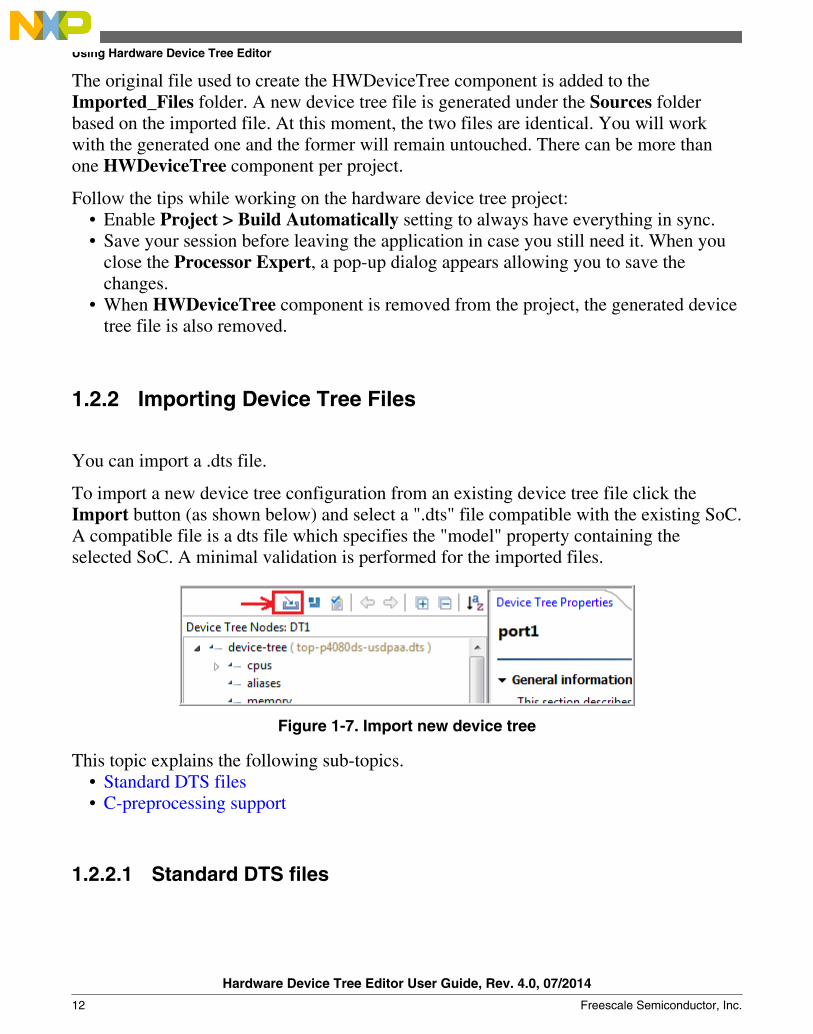
To import a new device tree configuration from an existing device tree file click theImport button (as shown below) and select a ".dts" file compatible with the existing SoC.A compatible file is a dts file which specifies the "model" property containing theselected SoC. A minimal validation is performed for the imported files.
Figure 1-7. Import new device tree
This topic explains the following sub-topics.• Standard DTS files• C-preprocessing support
1.2.2.1 Standard DTS files
Using Hardware Device Tree Editor
Hardware Device Tree Editor User Guide, Rev. 4.0, 07/2014
12 Freescale Semiconductor, Inc.

The standard DTS files are those files that contain the textual representation of a devicetree consumed by a DTC. These files may be used also like input for DTC, without anyprocessing of Hardware Device Tree Tool.
1.2.2.2 C-preprocessing support
Some of the DTS files may contain C-preprocessor syntax that is not supported by DTCtool. This syntax should be supported in preprocessed phase by the Hardware DeviceTree tool. The #define directives or other C-preprocessor syntax should be defined inincluded C-header files. At importing the identifiers are replaced with defined values.
Figure 1-8. C-header file that define used directives
Chapter 1 QorIQ Configuration and Validation Suite Device Tree Editor
Hardware Device Tree Editor User Guide, Rev. 4.0, 07/2014
Freescale Semiconductor, Inc. 13

Figure 1-9. Original DTS files that contain C-preprocessor syntax
Using Hardware Device Tree Editor
Hardware Device Tree Editor User Guide, Rev. 4.0, 07/2014
14 Freescale Semiconductor, Inc.

Figure 1-10. Generated DTS file consumed by DTC
1.2.3 Modify Hardware Device Trees
You can work on the hardware device tree component and modify it along with itsproperties using the GUI editor as well as the text editor.
This topic explains the following sub-topics.• GUI Editor• Text Editor
1.2.3.1 GUI Editor
Chapter 1 QorIQ Configuration and Validation Suite Device Tree Editor
Hardware Device Tree Editor User Guide, Rev. 4.0, 07/2014
Freescale Semiconductor, Inc. 15

When the HWDeviceTree component is selected in the Project Explorer, theComponent Inspector opens displaying the GUI editor and the hardware device treeproperties. This view is split in two parts, a tree structure that handles the nodes, and theDevice Tree Properties view that handles the properties.
Figure 1-11. Device Tree GUI Editor - DeviceTree and Device Tree Properties Views
The hardware device tree nodes are represented in a tree structure. Each node selectionmakes the corresponding properties display in the Device Tree Properties view. TheDevice Tree Properties view displays a list of properties along with the short details ofthe node. You can activate the dynamic context help by pressing F1 key after selectingthe required node for which you want to view the dynamic context help.
Using Hardware Device Tree Editor
Hardware Device Tree Editor User Guide, Rev. 4.0, 07/2014
16 Freescale Semiconductor, Inc.
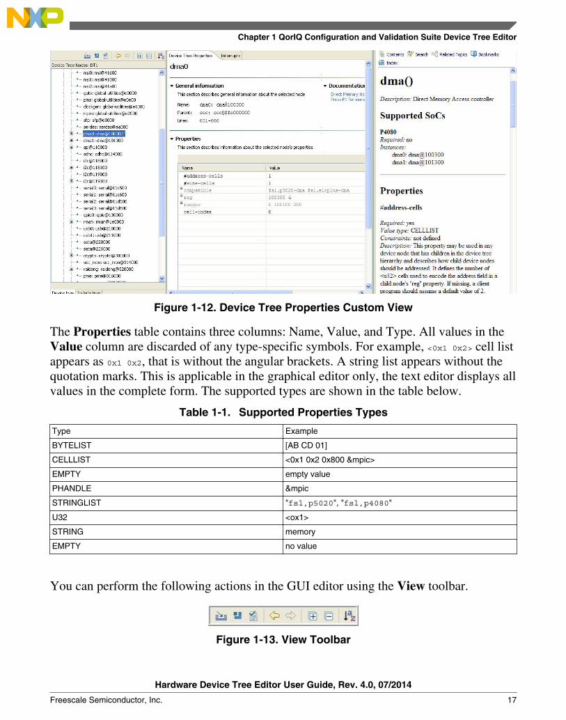
Figure 1-12. Device Tree Properties Custom View
The Properties table contains three columns: Name, Value, and Type. All values in theValue column are discarded of any type-specific symbols. For example, <0x1 0x2> cell listappears as 0x1 0x2, that is without the angular brackets. A string list appears without thequotation marks. This is applicable in the graphical editor only, the text editor displays allvalues in the complete form. The supported types are shown in the table below.
Table 1-1. Supported Properties Types
Type Example
BYTELIST [AB CD 01]
CELLLIST <0x1 0x2 0x800 &mpic>
EMPTY empty value
PHANDLE &mpic
STRINGLIST "fsl,p5020", "fsl,p4080"
U32 <ox1>
STRING memory
EMPTY no value
You can perform the following actions in the GUI editor using the View toolbar.
Figure 1-13. View Toolbar
Chapter 1 QorIQ Configuration and Validation Suite Device Tree Editor
Hardware Device Tree Editor User Guide, Rev. 4.0, 07/2014
Freescale Semiconductor, Inc. 17

• Import a new device tree file.• Include a device tree file.• Perform manual validation against the hardware device tree.• Tree navigation using Go back and Go forward icons from the View toolbar.• Expand/collapse nodes from the toolbar or using the context menu.• Sort the nodes in ascending/descending order.
• Context help support for hardware device tree nodes:
Select the required node in the tree structure and open the Eclipse context help bypressing F1 on Windows and Ctrl+F1 on Linux host. The nodes that have nodocumentation available are marked in the Device Tree Properties view.
Figure 1-14. Node with No Documentation Available
You can edit existing documentation or add missing documentation by performing thefollowing steps:
1. Edit existing file or create a new html file at the location <layout>eclipse/plugins/com.freescale.processorexpert.doc.qoriq.dt/html keeping the same format; the nameof the file must be identical with the name of the node, that is <node-name>.html.
2. If you are creating a new html file, add a new entry in <layout>eclipse/plugins/com.freescale.processorexpert.doc.qoriq.dt/contexts.xml for the new file.
3. Close the Eclipse IDE.4. Open Command Prompt and launch Eclipse using the following command:
>eclipse.exe --clean
This topic contains the following sub-topics:• Include Tree• Interrupts View• Memory Map View
1.2.3.1.1 Include Tree
Using Hardware Device Tree Editor
Hardware Device Tree Editor User Guide, Rev. 4.0, 07/2014
18 Freescale Semiconductor, Inc.

The Include Tree tab in the Component Inspector represents the hierarchy of theincluded hardware device tree files.
The Include Tree tab allows easy navigation among all hardware device tree fragments:dts or dtsi.
Figure 1-15. Include Tree Tab in Component Inspector
The Include Tree tab displays three types of files:• merged hardware device tree file, which represents the all-in-one file merging all
nodes and properties from multiple hardware device trees in a single file.• top-level hardware device tree file, which is the first dts including other hardware
device tree(s).• included files representing fragments with /include/ statement, usually dtsi files.
Chapter 1 QorIQ Configuration and Validation Suite Device Tree Editor
Hardware Device Tree Editor User Guide, Rev. 4.0, 07/2014
Freescale Semiconductor, Inc. 19

1.2.3.1.2 Interrupts View
In the Interrupts view of the hardware device tree, a logical interrupt tree exists thatrepresents the hierarchy and routing of interrupts in the platform hardware. You can viewthis interrupt tree in the Component Inspector when selecting an existing hardwaredevice tree component.
Figure 1-16. Interrupts View in Component Inspector
The left side of the Interrupts view displays the actual representation of the Interrupttree, starting from the root interrupt controller. When you select an element in theInterrupt tree, a table appears on the right side listing the interrupt sources for theselected hardware device tree node. Each row in the table provides a user-friendly viewof a decoded interrupt specifier, and each column in the table represents a specific cell ofthe interrupt specifier.
You can edit the Interrupts table for each node selected from the hardware device tree.An interrupt tree may contain special nodes called interrupt nexuses that map from oneinterrupt domain to another interrupt domain. When you select an interrupt nexus node inthe Interrupt tree, the Domain map table appears below the Interrupts table on theright side. The Domain Map table allows you to perform interrupt domain mapping forthe selected interrupt nexus.
Using Hardware Device Tree Editor
Hardware Device Tree Editor User Guide, Rev. 4.0, 07/2014
20 Freescale Semiconductor, Inc.

Figure 1-17. Interrupts Tree - Nexus Nodes and Domain Map
1.2.3.1.3 Memory Map View
The Memory Map view displays the decoded memory blocks associated with a hardwaredevice component.
You can view a hardware device tree as a representation of different Local AccessWindows (LAWs) within a device. For example, according to the P4080 ReferenceManual, you can define the p4080 address map using a set of maximum 32 LAWs. Anexample of such window is the Configuration Control and Status Register (CCSR) areadefined by soc node in the hardware device tree. All LAWs can be relocated within theentire address space of the platform. Each of these LAWs maps a programmable 4-Kbiteto 64-Gbyte region of the local 36-bit address space to a specified target interface, such asDDR Controller, Localbus, and PCI Express Controller.
Chapter 1 QorIQ Configuration and Validation Suite Device Tree Editor
Hardware Device Tree Editor User Guide, Rev. 4.0, 07/2014
Freescale Semiconductor, Inc. 21

Figure 1-18. LAW Defined Inside Hardware Device Tree
Each hardware device tree node having reg and ranges properties defines memory rangesinside or outside CCSR window. The following figures show an example of such node.
Figure 1-19. reg Property Definition Inside Hardware Device Tree
Using Hardware Device Tree Editor
Hardware Device Tree Editor User Guide, Rev. 4.0, 07/2014
22 Freescale Semiconductor, Inc.

Figure 1-20. ranges Property Definition Inside Hardware Device Tree
In (Figure 1-18), pci2 has one block of memory mapped register starting at F_FE20_2000with size 4-Kbyte in the SoC. There are two pci2 ranges (Figure 1-20) within the entireaddress space which can be accessed by a load or store operation. The first pci2 memoryblock starts at 0xC_4000_0000 with size of 512-MByte; the second pci2 block starts ataddress 0xF_F802_0000 with size of 64-Kbyte.
Once all memory blocks are decoded and gathered, they can be visually represented inthe Memory Map view. The Memory Map view pops-up automatically with the createdmemory block areas when a hardware device tree component is selected in theComponent Inspector . The Memory Map view displays its content created on the basisof DTS file that comes with the component. Block highlighting is available in theMemory Map view. Moreover, selecting a block in the Memory Map view triggers anode selection in the graphical hardware device tree.
Chapter 1 QorIQ Configuration and Validation Suite Device Tree Editor
Hardware Device Tree Editor User Guide, Rev. 4.0, 07/2014
Freescale Semiconductor, Inc. 23
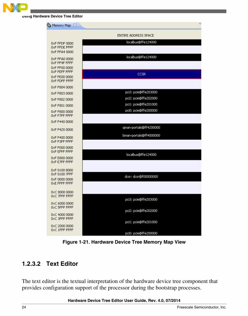
Figure 1-21. Hardware Device Tree Memory Map View
1.2.3.2 Text Editor
The text editor is the textual interpretation of the hardware device tree component thatprovides configuration support of the processor during the bootstrap processes.
Using Hardware Device Tree Editor
Hardware Device Tree Editor User Guide, Rev. 4.0, 07/2014
24 Freescale Semiconductor, Inc.
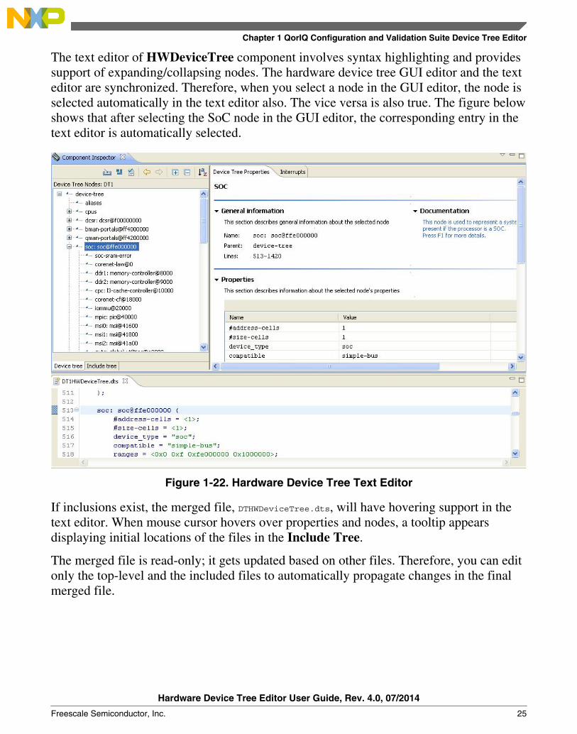
The text editor of HWDeviceTree component involves syntax highlighting and providessupport of expanding/collapsing nodes. The hardware device tree GUI editor and the texteditor are synchronized. Therefore, when you select a node in the GUI editor, the node isselected automatically in the text editor also. The vice versa is also true. The figure belowshows that after selecting the SoC node in the GUI editor, the corresponding entry in thetext editor is automatically selected.
Figure 1-22. Hardware Device Tree Text Editor
If inclusions exist, the merged file, DTHWDeviceTree.dts, will have hovering support in thetext editor. When mouse cursor hovers over properties and nodes, a tooltip appearsdisplaying initial locations of the files in the Include Tree.
The merged file is read-only; it gets updated based on other files. Therefore, you can editonly the top-level and the included files to automatically propagate changes in the finalmerged file.
Chapter 1 QorIQ Configuration and Validation Suite Device Tree Editor
Hardware Device Tree Editor User Guide, Rev. 4.0, 07/2014
Freescale Semiconductor, Inc. 25

Figure 1-23. Origin of Included Files
Hyperlink detection is also supported for /include/ declarations and hardware device treereferences. Use CTRL+left click combination on these statements to change the contextin the referred file or node.
Using Hardware Device Tree Editor
Hardware Device Tree Editor User Guide, Rev. 4.0, 07/2014
26 Freescale Semiconductor, Inc.
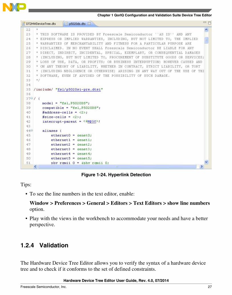
Figure 1-24. Hyperlink Detection
Tips:
• To see the line numbers in the text editor, enable:
Window > Preferences > General > Editors > Text Editors > show line numbersoption.
• Play with the views in the workbench to accommodate your needs and have a betterperspective.
1.2.4 Validation
The Hardware Device Tree Editor allows you to verify the syntax of a hardware devicetree and to check if it conforms to the set of defined constraints.
Chapter 1 QorIQ Configuration and Validation Suite Device Tree Editor
Hardware Device Tree Editor User Guide, Rev. 4.0, 07/2014
Freescale Semiconductor, Inc. 27

There are two approaches to display errors: using markers in the Eclipse Problems viewor using decorators in the Properties custom view table.
This topic contains the following sub-topics:• Syntax Validation• Property Constraints
1.2.4.1 Syntax Validation
Using markers, the error checking is performed for the following:• Syntax errors (inappropriate format)• More than one root node• Duplicate node labels• Undefined node reference• Properties do not preceding sub-nodes
In case of inaccuracies, the text editor displays the markers on the incorrect lines. Themarkers are also visible in the Problems view.
Figure 1-25. Errors Detection Using Markers
It is recommended to not rely on the errors displayed in the GUI tree because errors in thetree configuration might represent incorrect node hierarchy and display inaccurate tree.You can turn on/off the validation against the device tree bindings in the Device Tree
Using Hardware Device Tree Editor
Hardware Device Tree Editor User Guide, Rev. 4.0, 07/2014
28 Freescale Semiconductor, Inc.

Settings page (Figure 1-32). If it is enabled, the validation starts automatically wheneverchanges occur in the hardware device tree. You can also perform validation manuallyusing the third option in the View toolbar (Figure 1-13).
1.2.4.2 Property Constraints
Each hardware device tree node is completed and distinguished by an XML "binding".The binding describes which properties are required, which are optional, what eachproperty means and what constraints are to be met. The repository of hardware devicetree bindings is stored at PEx_Data\Beans\HWDeviceTree\dts_bindings.
The xml binding keeps information about the list of devices supported by the node, nodeinstances, sub-nodes, properties, constraints, and example. The following figure showsthe structure of a node and a property.
Figure 1-26. Xml Node and Property Schema
Following are the types of constraints that can be assigned to a property:• <type> - specifies the type of a property value• <editable> - specifies whether or not the property can be modified• <min-size>, <max-size> - specifies the minimum and maximum number of items
allowed in a property cell• <value-list> - specifies a set of allowed values for a property• <range> - bounds a numeric value between minimum and maximum values; it can also
force a property value to match a regular expression.
Take an example where you have the dma-channel@0 node as follows:
Chapter 1 QorIQ Configuration and Validation Suite Device Tree Editor
Hardware Device Tree Editor User Guide, Rev. 4.0, 07/2014
Freescale Semiconductor, Inc. 29

dma-channel@0 {compatible = "fsl,p5020-dma-channel", "fsl,eloplus-dma-channel";reg = <0x0 0x80>;cell-index = <0>;interrupts = <28 2 0 0>;};
dma-channel@100 {compatible = "fsl,p5020-dma-channel", "fsl,eloplus-dma-channel";reg = <0x100 0x80>;cell-index = <2>;interrupts = <30 2 0 0>;};
Assume you want to define the following constraints:• restrict the type of interrupts property to EMPTY for all dma-channel instances• for dma-channel@0, define reg property
• to have at least 3 items in its value• first item to be in [0xA, 0xC] range• second item to be in [0x0, 0x400] range
• for dma-channel@100• compatible property to be non-editable• to have exactly 3 items in its value
Then the dma-channel.xml file will be modified as shown in the following figure. Using thisrepresentation, you can compare the values set against the device tree bindings.
Using Hardware Device Tree Editor
Hardware Device Tree Editor User Guide, Rev. 4.0, 07/2014
30 Freescale Semiconductor, Inc.
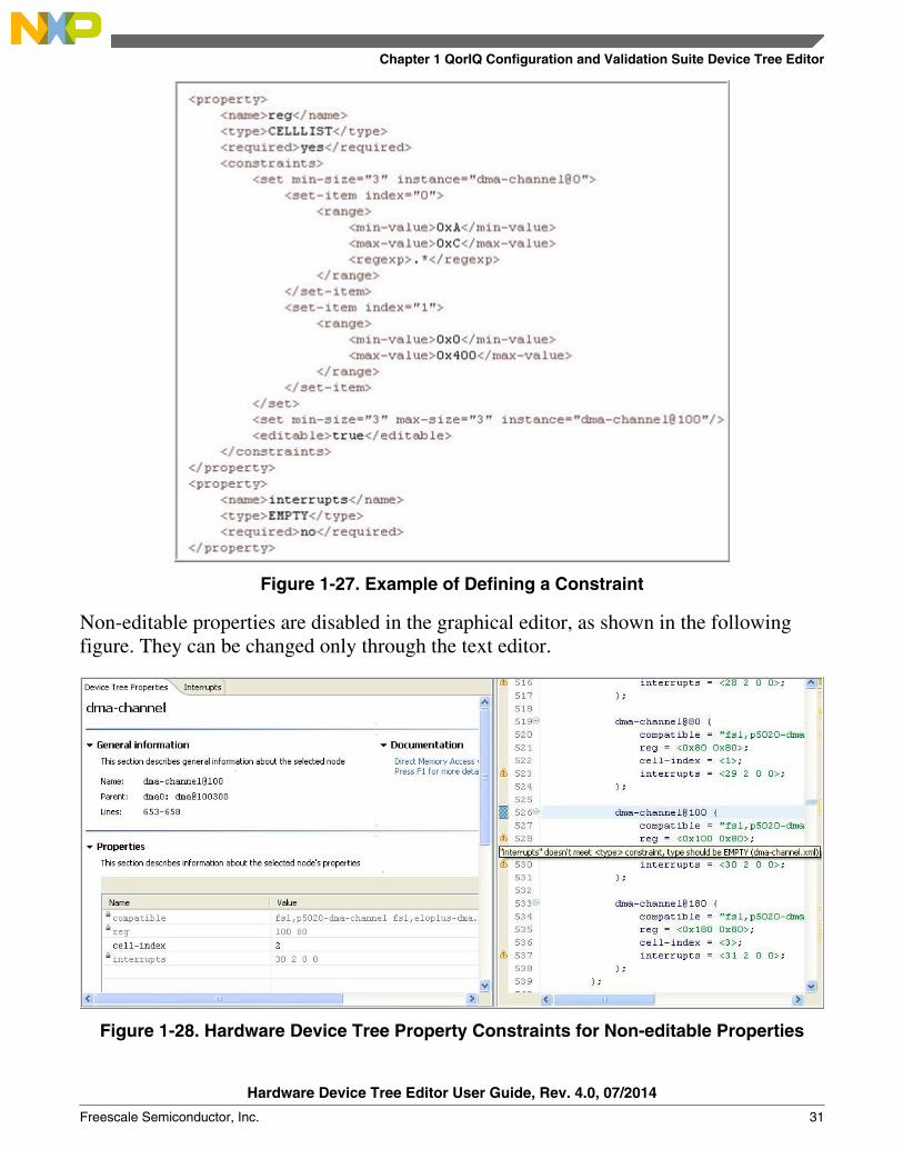
Figure 1-27. Example of Defining a Constraint
Non-editable properties are disabled in the graphical editor, as shown in the followingfigure. They can be changed only through the text editor.
Figure 1-28. Hardware Device Tree Property Constraints for Non-editable Properties
Chapter 1 QorIQ Configuration and Validation Suite Device Tree Editor
Hardware Device Tree Editor User Guide, Rev. 4.0, 07/2014
Freescale Semiconductor, Inc. 31

Setting these constraints produce the following warnings in the Problems view:• "interrupts" does not meet <type> constraint for all dma-channel instances from all
dma nodes (4 instances x 2 nodes)• "reg" does not meet <min-size> constraint at dma-channel@0 and dma-channel@100 instances
(there are 2 items and the constraint requires minimum 3)• "reg" does not meet <min-value> constraint at index 0 at dma-channel@0 instances: item at
index 0 is 0x0 and the constraint requires a value between 0xA, 0xC
Figure 1-29. Hardware Device Tree Property Constraint Warnings
1.2.5 Search in Hardware Device Trees
Use the Search view to search a particular information in the project's device tree files.
The Search view can be opened in three ways:• Select Search > Search > Device Tree Search in the main menu bar.• Search option from the context menu of the hardware device tree graphical editor.• Use the shortcut CTRL+ALT+H.
There are three options that specify the criteria based on which you can search the text:• Case sensitive• Whole word• Regular expression
Using Hardware Device Tree Editor
Hardware Device Tree Editor User Guide, Rev. 4.0, 07/2014
32 Freescale Semiconductor, Inc.
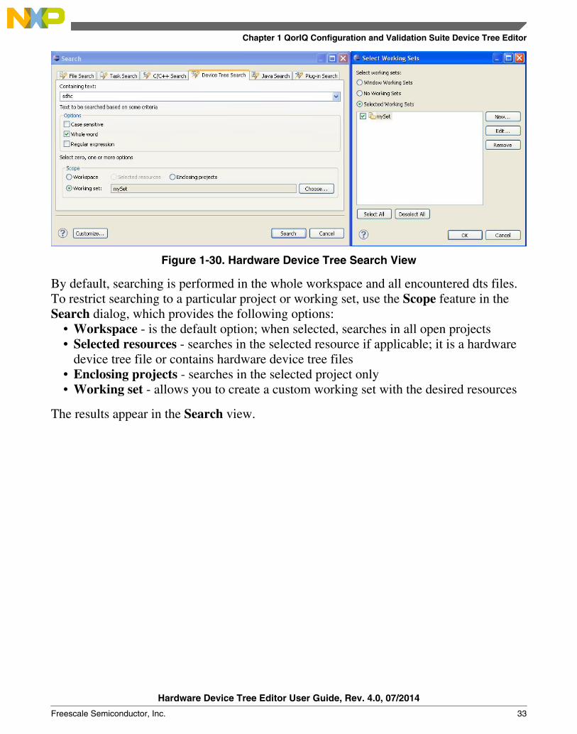
Figure 1-30. Hardware Device Tree Search View
By default, searching is performed in the whole workspace and all encountered dts files.To restrict searching to a particular project or working set, use the Scope feature in theSearch dialog, which provides the following options:
• Workspace - is the default option; when selected, searches in all open projects• Selected resources - searches in the selected resource if applicable; it is a hardware
device tree file or contains hardware device tree files• Enclosing projects - searches in the selected project only• Working set - allows you to create a custom working set with the desired resources
The results appear in the Search view.
Chapter 1 QorIQ Configuration and Validation Suite Device Tree Editor
Hardware Device Tree Editor User Guide, Rev. 4.0, 07/2014
Freescale Semiconductor, Inc. 33

Figure 1-31. Device Tree Search View Results
1.2.6 Generate Device Tree Blob
The Hardware Device Tree Editor enables you to generate device tree binaries if a devicetree compiler is available.
You can find the DTC settings in the Device Tree Compiler page of the Preferencesdialog box, as shown below, which appears on selecting Window > Preferences >Processor Expert > Device Tree Settings.
You can change the default settings. If this functionality is not required, it can beswitched off by clearing the Configure arguments to generate device trees checkbox.
Using Hardware Device Tree Editor
Hardware Device Tree Editor User Guide, Rev. 4.0, 07/2014
34 Freescale Semiconductor, Inc.

Figure 1-32. Device Tree Settings Page
To generate DTB files, select Project > Generate Processor Expert Code from the IDEmenu bar. The code is generated per project, therefore, the device tree blobs are createdfor all encountered device tree sources in the opened projects. The resultant device treeblob files are added to the Generated_Code folder, as shown in the following figure.
Chapter 1 QorIQ Configuration and Validation Suite Device Tree Editor
Hardware Device Tree Editor User Guide, Rev. 4.0, 07/2014
Freescale Semiconductor, Inc. 35

Figure 1-33. DTB File Generation
1.2.7 Known Issues/Limitations
To see a list of known issues and limitations, refer the ReadMe.html file.
Using Hardware Device Tree Editor
Hardware Device Tree Editor User Guide, Rev. 4.0, 07/2014
36 Freescale Semiconductor, Inc.

How to Reach Us:
Home Page:freescale.com
Web Support:freescale.com/support
Information in this document is provided solely to enable system and
software implementers to use Freescale products. There are no express
or implied copyright licenses granted hereunder to design or fabricate
any integrated circuits based on the information in this document.
Freescale reserves the right to make changes without further notice to
any products herein. Freescale makes no warranty, representation, or
guarantee regarding the suitability of its products for any particular
purpose, nor does Freescale assume any liability arising out of the
application or use of any product or circuit, and specifically disclaims
any and all liability, including without limitation consequential or
incidental damages. “Typical” parameters that may be provided in
Freescale data sheets and/or specifications can and do vary in different
applications, and actual performance may vary over time. All operating
parameters, including “typicals,” must be validated for each customer
application by customer's technical experts. Freescale does not convey
any license under its patent rights nor the rights of others. Freescale
sells products pursuant to standard terms and conditions of sale, which
can be found at the following address: freescale.com/
SalesTermsandConditions.
Freescale, the Freescale logo, AltiVec, C-5, CodeTest, CodeWarrior,
ColdFire, ColdFire+, C-Ware, Energy Efficient Solutions logo, Kinetis,
mobileGT, PowerQUICC, Processor Expert, QorIQ, Qorivva, StarCore,
Symphony, and VortiQa are trademarks of Freescale Semiconductor,
Inc., Reg. U.S. Pat. & Tm. Off. Airfast, BeeKit, BeeStack, CoreNet,
Flexis, Layerscape, MagniV, MXC, Platform in a Package, QorIQ
Qonverge, QUICC Engine, Ready Play, SafeAssure, SafeAssure logo,
SMARTMOS, Tower, TurboLink, Vybrid, and Xtrinsic are trademarks of
Freescale Semiconductor, Inc. All other product or service names are
the property of their respective owners.
© 2012–2014 Freescale Semiconductor, Inc.
Document Number QCSHWDTUGRevision 4.0, 07/2014