hardware security evaluation of intel max 10 fpgas
TRANSCRIPT

Hardware security evaluation of Intel MAX 10 FPGAs Hardwear.IO 2019 Conference, The Hague, Netherlands, 23-27 September 2019
Hardware security evaluation ofIntel® MAX 10 FPGAs:
from feasibility study to security boundaries
Dr Sergei Skorobogatovhttp://www.cst.cam.ac.uk/~sps32 email: [email protected]
Dept of Computer Science and Technology

Hardware security evaluation of Intel MAX 10 FPGAs Hardwear.IO 2019 Conference, The Hague, Netherlands, 23-27 September 2019
2
Outline• Present my evaluation of HW security in Intel MAX 10 FPGAs• Discuss challenges in implementation of some attack methods• Summarise certain threats arising during implementation of attacks• Future work• Conclusion
Hardware security evaluation of Intel MAX 10 FPGAs Hardwear.IO 2019 Conference, The Hague, Netherlands, 23-27 September 2019
3
Introduction• Hardware Security is important
– data and IP protection
– cyber security and preventing attacks on services
– countermeasures against all known attacks
– educate hardware engineers
• Hardware Security is about finding flaws and fixing them– evaluation of implemented security features and improving them
• Hardware Security challenges– new attack technologies
– modern fabrication processes (7nm, 10nm, 14nm, 28nm, 40nm, 45nm, 55nm)
– developing countermeasures through understanding of flaws
– prediction of new attack methods

Hardware security evaluation of Intel MAX 10 FPGAs Hardwear.IO 2019 Conference, The Hague, Netherlands, 23-27 September 2019
4
Why security of MAX 10 FPGA is important?• Designed for security applications
– no external Flash with configuration bitstream
– AES encryption option for bitstream protection
– security fuses: Verify Protect, Encrypted POF, JTAG Security
– positioned as secure device
– no detailed documentation on JTAG commands and security features
• Suitable candidate to mitigate modification attacks– can prevent Trojan insertions into SPI flash on PC motherboards (Supermicro
server motherboards compromised in October 2018)
• Pros– small size and low cost
– two configuration images: safe update and easy recovery on errors
• Cons– SRAM FPGA array: prone to soft errors
– keys are stored in Flash

Hardware security evaluation of Intel MAX 10 FPGAs Hardwear.IO 2019 Conference, The Hague, Netherlands, 23-27 September 2019
5
• Design process– compile design into *.sof file which can only be loaded into SRAM
– convert the *.sof file into *.pof file for programming into on-chip Flash• if necessary encrypt the bitstream and add *.ekp file with AES key
– add security fuses and configuration options to *.pof file
• Without any security fuses activated in 10M08SCE144– ICB 0x00000 – 0x007FF read protected, write once after erase
– UFM 0x00800 – 0x1CFFF read and write access
– CFM0 0x1D000 – 0x4E7FF read and write access
– SFM 0x4E800 – 0x4EFFF read access, write protected
• Security Fuses– Verify Protect: 0x1D000 – 0x4E7FF is read protected in JTAG, but not in *.sof file
– Encrypted POF Only: blocks direct SRAM upload (*.sof file), but no effect on JTAG
– JTAG Security: no access via JTAG – highest security but no reprogrammability
• Security flaw: only the combination of Verify Protect + Encrypted POF could prevent access to the configuration bitstream
Security in MAX 10 FPGAs

Hardware security evaluation of Intel MAX 10 FPGAs Hardwear.IO 2019 Conference, The Hague, Netherlands, 23-27 September 2019
6
Security in MAX 10 FPGAs• Bitstream configuration is protected against modification
– *.sof file has 16-byte number unique for each design plus CRC at the end
– *.pof file can be modified as it is a Flash image, but chip will not boot if it fails checks
• Fuse setting in *.pof file– Verify Protect fuse
• 030h: 0F,A5,48,6C; 01D007h: D2; 01D00Ch: F3,0C,59
– Encrypted bitstream• 000h: 16-byte scrambled key (01234..EF => 3B7F195D2A6E084C); 028h: 0F,A5,48,6C;
01D007h: C2; 01D00Ch: E2,0C,98
– Encrypted POF Only fuse• 014h: 0F,A5,48,6C; 01D007h: C3; 01D00Ch: F2,0C,58
– Secured JTAG fuse• 01Ch: 0F,A5,48,6C; 01D007h: C6; 01D00Ch: A7,0C,58
• STAPL file (from *.pof for JTAG programming by user) is obfuscated– variables and subroutines have obscured names (A12, V185, L107)
– IRSCAN, DRSCAN still present and PRINT commands can be added

Hardware security evaluation of Intel MAX 10 FPGAs Hardwear.IO 2019 Conference, The Hague, Netherlands, 23-27 September 2019
7
Attack methods• Invasive attacks (high cost and setup time from weeks to months)
– evaluation of Flash memory cells size
– evaluation of FPGA core logic
– evaluation of JTAG logic complexity
• Semi-invasive attacks (medium cost and setup time in weeks)– optical fault injection
• Non-invasive attacks (low-cost and setup time from hours to days)– undocumented JTAG commands
– data remanence
– power analysis
– electromagnetic analysis
– power glitching
– electromagnetic pulses

Hardware security evaluation of Intel MAX 10 FPGAs Hardwear.IO 2019 Conference, The Hague, Netherlands, 23-27 September 2019
8
Invasive Attacks• Offer unlimited capabilities, hence, are the most dangerous
– high cost can only be afforded by limited number of attackers (organisations)
– require highly skilled and knowledgeable attackers
– time consuming: could take prohibitively long to perform
• Backside polishing and deprocessing down to polysilicon layer– fabrication process is CMOS 55nm
– JTAG logic complexity is approximately 60’000 gates

Hardware security evaluation of Intel MAX 10 FPGAs Hardwear.IO 2019 Conference, The Hague, Netherlands, 23-27 September 2019
9
Invasive Attacks• Flash memory array
– unusually large memory cells 280×660 nm• ten times larger than similar cells of embedded Flash in microcontrollers and SoCs
– visible with optical microscope: more likely to succeed with semi-invasive attacks

Hardware security evaluation of Intel MAX 10 FPGAs Hardwear.IO 2019 Conference, The Hague, Netherlands, 23-27 September 2019
10
Invasive Attacks• Do those attacks pose any danger to the attacker?
– most invasive attacks involve Chemistry
– Chemistry is a science of …
• Deprocessing– Hydrofluoric acid for etching SiO2 and Si
– Piranha solution and solvents for cleaning
• All chemicals are poisonous, hence, protective clothes and training– HF: LD50 = 0.1 g/kg
– H2O2: LD50 = 2 g/kg
– H2SO4: LD50 = 2.1 g/kg
– Acetone: LD50 = 7 g/kg
– NaOH/KOH (pipe cleaner): LD50 = 0.25 g/kg
– Petrol/Gasoline/Diesel: LD50 = 3…7 g/kg
– Alcohol: LD50 = 7 g/kg
– NaCl (table salt): LD50 = 3 g/kg
– Water: LD50 = 90 g/kg

Hardware security evaluation of Intel MAX 10 FPGAs Hardwear.IO 2019 Conference, The Hague, Netherlands, 23-27 September 2019
11
Semi-Invasive Attacks• Experimental setup
– 10M08SCE144 mechanically open from rear side to access bulk silicon
– special adapter board with ZIF socket to hold the sample under microscope
– JTAG commands synchronised with laser pulses using custom test board
– PC software to communicate with the board and move XY stage under microscope

Hardware security evaluation of Intel MAX 10 FPGAs Hardwear.IO 2019 Conference, The Hague, Netherlands, 23-27 September 2019
12
Semi-Invasive Attacks• Experimental setup
– 10M08SCE144 device with test data and different fuse settings
– infrared (1065nm) laser with 50mW output power during the boot process– scanning full surface of the die: 4300×4400µm2 with 100µm steps
• Results– light blue area – corrupted Flash, red area – disabled fuse

Hardware security evaluation of Intel MAX 10 FPGAs Hardwear.IO 2019 Conference, The Hague, Netherlands, 23-27 September 2019
13
Semi-Invasive Attacks• Scanning only the Flash area with Verify Protect fuse set
– 1000×1000µm2 with 10µm steps
– laser power at 50mW with optimised timing
– red area corresponds to disabled Verify Protect fuse

Hardware security evaluation of Intel MAX 10 FPGAs Hardwear.IO 2019 Conference, The Hague, Netherlands, 23-27 September 2019
14
Semi-Invasive Attacks• Scanning only the Flash area with JTAG Security fuse set
– 1000×1000µm2 with 10µm steps
– laser power at 50mW with optimised timing
– blue area corresponds to disabled JTAG Security fuse

Hardware security evaluation of Intel MAX 10 FPGAs Hardwear.IO 2019 Conference, The Hague, Netherlands, 23-27 September 2019
15
Semi-Invasive Attacks• Timing analysis for the optimal fault injection
– laser focused at one of the sensitive locations
– reading data from Flash
• Results– laser pulse overshooting TCK (Y – time before TCK in µs, X – time after TCK)
– laser pulse undershooting TCK (Y – laser pulse time in µs, X – time before TCK)
– only the time before TCK pulse matters

Hardware security evaluation of Intel MAX 10 FPGAs Hardwear.IO 2019 Conference, The Hague, Netherlands, 23-27 September 2019
16
Semi-Invasive Attacks• Do those attacks pose any danger to the attacker?
– many semi-invasive attacks involve Lasers
– Lasers could be invisible (UV, IR)
• Lasers are dangerous, hence, safety glasses and protective clothes– Class 3B lasers (>5 mW) can blind you
– Class 4 lasers (>300 mW) can cut and burn
• Lasers are used in medicine– cut tissues and medical treatment
– used in ophthalmology to cut tissues inside eye and remove unwanted pieces
– it is non-collimated laser beam that represents the biggest threat
– focused beams are almost fine unless they meet a mirror or white wall…

Hardware security evaluation of Intel MAX 10 FPGAs Hardwear.IO 2019 Conference, The Hague, Netherlands, 23-27 September 2019
17
Non-Invasive Attacks• Undocumented JTAG commands
– could there be any backdoors?
– sources: User Guides, BSDL files, convert *.pof into *.jam STAPL files
– scanning JTAG interface for the length of DR registers and their volatility
– observe power consumption to determine active commands
• Results– new commands: 008, 015, 090, 091, 1EE, 206, 207, 2B0, 2D0, 303, 3F5
– no obvious backdoors with none of the commands leaking any data
• Challenges– cannot be used if JTAG Security fuse is activated

Hardware security evaluation of Intel MAX 10 FPGAs Hardwear.IO 2019 Conference, The Hague, Netherlands, 23-27 September 2019
18
Non-Invasive Attacks• Data Remanence
– residual data left after chip erase operation
– full chip erasure disables all fuses
• Experimental setup– initiate Chip Erase operation and terminate power supply of the chip
• Challenges– cannot be used if JTAG Security fuse is activated
– recovery rate is about 97% but can be improved with power glitching

Hardware security evaluation of Intel MAX 10 FPGAs Hardwear.IO 2019 Conference, The Hague, Netherlands, 23-27 September 2019
19
Non-Invasive Attacks• Memory overwriting
– it is possible to change bits in both User and Configuration Flash from 1 to 0
– if checksums or signatures are leaked this could help with data extraction
– timing attack only leaks information within bus width (64 bits in small devices)
– power analysis could reveal single-bit changes in the memory
– when encryption is used a single-bit change results in multiple-bit change and this is easily detectable in the power trace
• Challenges– cannot be used if JTAG Security fuse is activated

Hardware security evaluation of Intel MAX 10 FPGAs Hardwear.IO 2019 Conference, The Hague, Netherlands, 23-27 September 2019
20
Non-Invasive Attacks• Power Analysis
– 10Ω resistor in power supply line (VCORE) and oscilloscope with differential probe
– record traces with different data and settings, then compare them
• Results– boot process from on-chip Flash
– extract timing parameters valuable for fault injection attacks

Hardware security evaluation of Intel MAX 10 FPGAs Hardwear.IO 2019 Conference, The Hague, Netherlands, 23-27 September 2019
21
Non-Invasive Attacks• Results
– averaging helps with noise reduction: no countermeasures implemented
– compare traces with different AES keys
– compare traces between normal and corrupted Flash
• Challenges– hard to manipulate with data as they are fetched from on-chip Flash
Hardware security evaluation of Intel MAX 10 FPGAs Hardwear.IO 2019 Conference, The Hague, Netherlands, 23-27 September 2019
22
Non-Invasive Attacks• Electromagnetic Emission Analysis
– observing leakages using a small magnetic coil or H-probe
– can be positioned above certain area on the chip– no need to remove the chip or cut power traces on PCB to insert 10Ω resistor
– usually requires pre-amplifier to boost the signal before feeding it into oscilloscope
• Results– much weaker signal compared to power analysis
– signal-to-noise ratio is worse than with power analysis
– contribution of the clock signal used by the FPGA design is significantly higher than contribution of the JTAG logic
– improvement from positioning the sensor above certain area is not very significant if the chip is still in package (0.6mm distance between package surface and die)

Hardware security evaluation of Intel MAX 10 FPGAs Hardwear.IO 2019 Conference, The Hague, Netherlands, 23-27 September 2019
23
Non-Invasive Attacks• Power glitching
– disrupt normal VCORE power supply with a glitch to cause controllable fault
– single supply devices (10M16SCE144) use internal regulator to get 1.2V from 3.3V
– dual supply devices (10M16DAF256) use external 1.2V power supply
• Results– dual supply devices are easier to glitch
– if the glitch goes too low it causes the device to reboot
– number of faults in Flash per full read
Single supply 10M16SCE1441.5V 5µs 1.45V 4µs 1.4V 4µs 1.3V 3.5µs
9 1706 1860 17
Dual supply 10M16DAF2560.6V 1.2µs 0.4V 0.7µs 0.3V 0.5µs 0.2V 0.4µs
241 650 13491 9954

Hardware security evaluation of Intel MAX 10 FPGAs Hardwear.IO 2019 Conference, The Hague, Netherlands, 23-27 September 2019
24
Non-Invasive Attacks• Fault injection using electromagnetic (EM) pulse
– setup was described in many publications: coil supplied with high voltage pulse
– fast changing magnetic field creates eddy current inside the chip that disrupts logic
– however, I went into difficulties trying to reproduce some parameters
• Challenge #1: what hardware to use for pulse generation– off-the-shelf setup or custom design
• HV pulse generator with leads to coil
• Signal Generator with HV amplifier and leads to coil
– wires introduce parasitic resistance, inductance and capacitance• pulse voltage is reduced
• pulse fronts become longer
• introduce unnecessary oscillations
– custom design could benefit from better control of the pulse parameters
– custom board could be brought closer to the device under test

Hardware security evaluation of Intel MAX 10 FPGAs Hardwear.IO 2019 Conference, The Hague, Netherlands, 23-27 September 2019
25
Electromagnetic pulse generation• Challenge #2: controlling the duration of the pulse
– the coil that is used for EM pulse injection has certain inductivity
– voltage across the coil:
v(t) = L di(t)/dt
– if we aim to have a fixed voltage pulse as defined in many publications
– average 10-wind coil has 100nH inductance
– at 100V the current will ramp at 1A/ns rate
– it would be very difficult to produce very long pulse• power supply run out of steam
• switch will be unable to hold the high current

Hardware security evaluation of Intel MAX 10 FPGAs Hardwear.IO 2019 Conference, The Hague, Netherlands, 23-27 September 2019
26
Electromagnetic pulse generation• Challenge #3: maintaining the pulse parameters
– the voltage across the coil can be maintained by a capacitor:
U = q/C
– once charged the capacitor will give away high current
– coil will be saturated at some point and turns into a resistor – a very low one (0.1Ω)
– maintaining voltage across the coil will become prohibitively hard• power supply goes belly up (I = U/R = 100V/0.1Ω = 1000A, P = UI = 100kW)
• transistor gets too stressed and starts smoking (channel R=0.01Ω, P = RI2 = 10kW)
• coil becomes too happy and starts firework

Hardware security evaluation of Intel MAX 10 FPGAs Hardwear.IO 2019 Conference, The Hague, Netherlands, 23-27 September 2019
27
Electromagnetic pulse generation• Challenge #4: stopping the pulse
– the coil accumulates energy in the form of magnetic field
– once the current is stopped the energy has to go somewhere and quickly
– flyback voltage across the coil H-field probe next to the coil
– guess which pulse will influence your device under test
– a 50V pulse could easily create 500V flyback which can be damaging• equipment (pulse generator)
• transistor
• insulation

Hardware security evaluation of Intel MAX 10 FPGAs Hardwear.IO 2019 Conference, The Hague, Netherlands, 23-27 September 2019
28
Electromagnetic pulse generation• Challenge #5: getting rid of the unwanted flyback pulse
– modify the pulse generation circuit
– test the result in real circuit

Hardware security evaluation of Intel MAX 10 FPGAs Hardwear.IO 2019 Conference, The Hague, Netherlands, 23-27 September 2019
29
Electromagnetic pulse generation• Finding suitable diodes
– can withstand high reverse voltage (300V…500V) and high peak current (0.5A…5A)
– the natural principle of the diode operation in forward voltage recovery
under stress (high reverse voltage) gets relaxed (zero voltage)
Hardware security evaluation of Intel MAX 10 FPGAs Hardwear.IO 2019 Conference, The Hague, Netherlands, 23-27 September 2019
30
Electromagnetic pulse generation• Finding suitable diodes
– the natural principle of the diode operation in forward voltage recovery
goes into sleep (to recover) ready to operate (recovered)

Hardware security evaluation of Intel MAX 10 FPGAs Hardwear.IO 2019 Conference, The Hague, Netherlands, 23-27 September 2019
31
Electromagnetic pulse generation• Finding suitable diodes
– how long does it sleep?• rectifying diode will do for about 100ns
– maybe there are better diodes?• the best are “super fast rectifying diodes” and “ultra fast rectifying diodes”
• but they are usually low-voltage and low-current devices (1N4148, 1N4151, DFLU1400)
• manufacturers often do not specify tFR but only tRR because it matters for switching PSU
Hardware security evaluation of Intel MAX 10 FPGAs Hardwear.IO 2019 Conference, The Hague, Netherlands, 23-27 September 2019
32
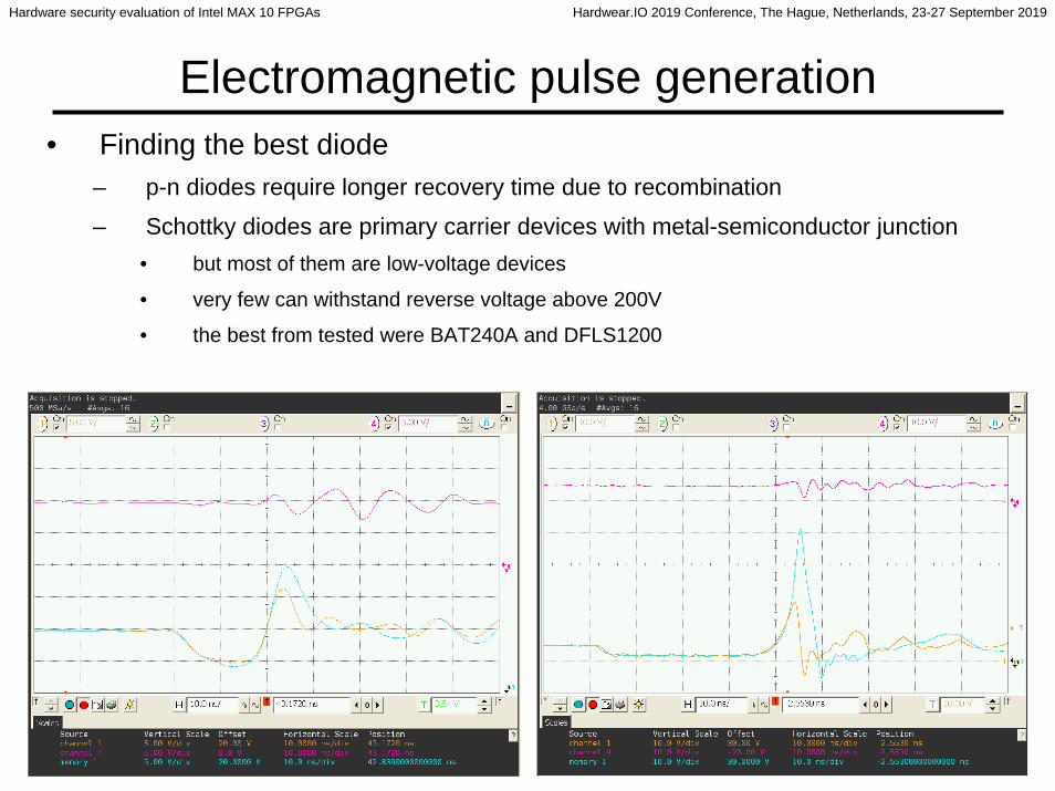
Electromagnetic pulse generation• Finding the best diode
– p-n diodes require longer recovery time due to recombination
– Schottky diodes are primary carrier devices with metal-semiconductor junction• but most of them are low-voltage devices
• very few can withstand reverse voltage above 200V
• the best from tested were BAT240A and DFLS1200

Hardware security evaluation of Intel MAX 10 FPGAs Hardwear.IO 2019 Conference, The Hague, Netherlands, 23-27 September 2019
33
Electromagnetic pulse generation• Finding the best diode
– will Schottky diode from other semiconductor material work better: GaAs, GaN, SiC
– GaN are very rare
– GaAs are low-voltage (VSKY10401406 is 40V max)
– SiC are very promising: high voltage, high temperature, fast rectifying• Tested STPSC406, GB01SLT12, IDV03S60C, CSD01060 (the best)

Hardware security evaluation of Intel MAX 10 FPGAs Hardwear.IO 2019 Conference, The Hague, Netherlands, 23-27 September 2019
34
Electromagnetic pulse generation• Finding the best diode
– still the best diode has the forward recovery time of 3ns (SiC CSD01060)
– datasheet on Infineon 5th Generation thinQTM SiC Schottky diode IDK02G65C5• “Revolutionary semiconductor material”, “No reverse recovery/ No forward recovery”
• BUT down the datasheet: QC = 4 nC, C = 9 pF (300V)
• 4 nC is somewhat 25 billions of electrons, enough to save 1 Gb of data on iPhone
• what is exactly “no time”?
• presumably less than something detectable by modern osclilloscopes: 1 ps
– any attempt to remove 4nC within 1ps will require the current I = q/t = 4000A
– SiC Schottky diode is vertical device with about 0.5mm working area• any attempt to remove the electrons out of the way from that space within 1ps will require
the speed V = l/t = 500,000,000 m/s which is greater than the speed of light
– the diode also has non-zero capacitance of the junction
– so, this magic device definitely worth looking at…

Hardware security evaluation of Intel MAX 10 FPGAs Hardwear.IO 2019 Conference, The Hague, Netherlands, 23-27 September 2019
35
Electromagnetic pulse generation• Finding the best diode
– testing IDK02G65C5 SiC 5th Generation thinQTM Schottky diode from Infineon
• No magic has happend– who writes the “Final Data Sheet” and who checks them?
– the best approach is to characterise the real pulse and benefit from flyback

Hardware security evaluation of Intel MAX 10 FPGAs Hardwear.IO 2019 Conference, The Hague, Netherlands, 23-27 September 2019
36
Non-Invasive Attacks• Electromagnetic Pulse glitching
– disrupt device operation with a glitch to cause controllable fault
– single supply devices (10M16SCE144) use internal regulator to get 1.2V from 3.3V
– dual supply devices (10M16DAF256) use external 1.2V power supply
• Results– single and dual supply devices are equally susceptible to EM glitching
– if the glitch is too high it causes the device to reboot
– number of faults in Flash per full read
Single supply 10M16SCE144190V 27ns 220V 30ns 260V 35ns 290V 40ns
26 80 184 352
Dual supply 10M16DAF256170V 31ns 200V 34ns 240V 30ns 285V 30ns
6 160 191 254

Hardware security evaluation of Intel MAX 10 FPGAs Hardwear.IO 2019 Conference, The Hague, Netherlands, 23-27 September 2019
37
Non-Invasive Attacks• Do those attacks pose any danger to the attacker?
– only if high voltages are involved
• Capacitors are dangerous– once charged they could hold voltage for days or even months
• Inductors are dangerous– if current through them is interrupted the voltage could surge to hundreds of volts
– electromagnetic pulse could easily destroy semiconductor devices

Hardware security evaluation of Intel MAX 10 FPGAs Hardwear.IO 2019 Conference, The Hague, Netherlands, 23-27 September 2019
38
Limitations and improvements• The features
– 55nm process is challenging for full reverse engineering– Flash memory cells are large– large memory size: Megabits– more efficient methods and solutions are necessary
• Proper memory encryption will pose additional challenges for finding keys and decryption algorithm
• Total lack of documentation will likely make the analysis very challenging with the need for silicon level reverse engineering

Hardware security evaluation of Intel MAX 10 FPGAs Hardwear.IO 2019 Conference, The Hague, Netherlands, 23-27 September 2019
39
Future Work• More research is needed for successful non-invasive attacks
– power analysis is unlikely to help with data extraction from Flash memory
– power glitching needs to be better tuned to bypass security fuses
– Electromagnetic fault injection has many benefits but still needs better tuning
• Collaboration with industry– bring new ideas and test new methods
– funding is essential, but it might be possible to go beyond state-of-the-art
• New methods in direct imaging of embedded memory– combined methods did work for semi-invasive techniques so should do for invasive
– more research and development is needed to find new innovative solutions
– the research paper about MAX 10 security will appear at the end of September 2019
– visit my homepage for latest news
http://www.cst.cam.ac.uk/~sps32/

Hardware security evaluation of Intel MAX 10 FPGAs Hardwear.IO 2019 Conference, The Hague, Netherlands, 23-27 September 2019
40
Conclusion• Intel MAX 10 FPGAs can be attacked with different methods
– Is this really a problem? The device is not certified for high level of security
• It is not always true that the latest devices on the market have the best hardware security features
– you never know how the security was implemented by the manufacturer
• There are many interesting targets for security research• But the most importantly…

Hardware security evaluation of Intel MAX 10 FPGAs Hardwear.IO 2019 Conference, The Hague, Netherlands, 23-27 September 2019
41
Conclusion• Be careful with lasers, chemicals, capacitors and inductors!