hawker 800xp refueling/defueling procedures (figures...
TRANSCRIPT

Hawker 800XP
Refueling/Defueling Procedures(Figures 8, 9, 10, 11, 12, 13, 14, 15 and 16)
Pressure Refueling
WARNING: THE AIRPLANE CAN BE PRESSURE REFUELLED WITH THE APU IN OPERATION. THIS DOCUMENT GIVES THE SPECIFIED INSTRUCTIONS FOR THE AIRPLANE CONFIGURATION.
WARNING: YOU CAN ONLY REFUEL THE AIRPLANE WITH THE APU IN OPERATION IF THE CONDITIONS THAT FOLLOW APPLY:•THE AIRPLANE IS PRESSURE REFUELLED, NOT GRAVITY REFUELLED•THE APU IS AN APPROVED RAYTHEON AIRCRAFT COMPANY
INSTALLATION•THE AMBIENT TEMPERATURE IS LESS THAN 40° C
WARNING: THE APU MUST NOT BE USED IF THE AIRPLANE CONTAINS OR WILL BE REFUELLED WITH A WIDE CUT FUEL e.g. JP4.
WARNING: DO NOT START THE APU WHILE REFUELLING IS IN PROGRESS.
LimitationsMaximum refuel pressure (gauge) 50 psi (3.515 kg/sq.cm)Maximum refuel rate 144 US gal/min. (120 Imp), (545 Liters)Maximum defuel suction 11.0 psi (0.773 kg/sq.cm)Minimum wing tank fuel loadwith full ventral tank. 1000 Ib each wing
Preparation for Pressure Refueling
(1)Make sure of the fuel load required.
CAUTION: LOOK FOR CONTAMINATION (OTHER THAN WATER) OF THE DRAINED SAMPLE
(2)Drain all water from the tanks.(3)Make sure that the fuel L and R PUMP switches are set to OFF(4)Energize the DC electrical power supplies.
(a) APU - Shut down (If applicable).(b) Battery switch - ON
NOTE: Paragraph (b) is only applicable if battery power is to be used for refueling.

(5) If airplane battery is the only source of electrical power, switch off all unnecessary loads.Examine wing FUEL contents indicators to check the correct fuel state if wings are to be only partially filled. Fuel contents indicators on MFD's are inoperative on battery only. Airplanes with Pro Line 21 will display fuel contents on the pilot's FMS CDU (Control Display Unit) accessed through the CDU IDX (Index) key.
(6) Open both LP COCKS (Lever fully up).(7) Make sure WING FUEL/X FEED/TRANSFER lever is selected to WING FUEL (Lever
fully up).(8) Make sure AUX FUEL TRANSFER lever is selected closed (Lever fully up).
Test Refuel Control System Before Refueling
(1) Set MASTER switch ON and make sure the MASTER VALVE indicator shows OPEN. (2) Set the VENTRAL and L and R WING switches to REFUEL.(3) Do a system check using 'press to test' facility.(a) Press L OVERFLOW indicator and make sure that: •OVERFLOW is shown•MASTER VALVE shuts•All three tank REFUEL VALVES SHUT
(b) Release pressure on L OVERFLOW indicator and make sure that all indicators show the same indications as those at end of paragraph (2).
(c) Do paragraph (a) and (b) again for R OVERFLOW indicator.(d) Push VENTRAL FULL indicator and make sure that:• Tank FULL indicator comes on•VENTRAL tank refuel indicator changes from OPEN to SHUT
(e) Release pressure on VENTRAL FULL indicator and make sure that all indicators show the same indications as those at end of paragraph (2).
(f) Do paragraph (d) and (e) again, for L & R WING tank FULL indicators.(4) Set the VENTRAL and L and R WING tank REFUEL switches to OFF Make sure all
VALVE indicators go back to SHUT(5) Push the OVERPRESS indicator for more than 1 second, release pressure and make sure
that:(a)OVERPRESS indicator comes on.(b)MASTER VALVE indicator displays SHUT and stays SHUT(c)Set MASTER Refuel Switch to OFF, then after approximately 2 seconds select ON.
Make sure the MASTER VALVE reopens.
Connect and Disconnect the Refuel Hose (Figures 8 and 9)
(1) To remove the cover from the airplane coupling:(a)Push finger towards the center to release the handle, then turn the handle
counterclockwise to remove the cover.(2) To connect the hose end pressure controller (HEPC):
(a)Make sure the air pressure gauge shows 50 psi.(b)Remove the dust cover.

(c)Hold the handwheel, push up the HEPC and put its nose coupling into engagement with the airplane coupling; turn the HEPC clockwise to the limit of its travel, approximately 40°.
(d)Connect the HEPC grounding clip to the grounding point. Move the valve operation lever to the open position to engage the interlock.
(3) To disconnect the HEPC:(a)Move the valve operation lever to the closed position.(b)Disconnect the HEPC grounding clip from the grounding point.(c)Turn the handwheel counterclockwise and disengage the HEPC from the airplane
coupling.(d)Install the cover to the HEPC.
(4) To install cover to the airplane coupling:(a)Put the lanyard in the container on the cover.(b)Install the cover to the coupling.(c)Turn the cover clockwise to lock and then close the handle.
Pressure Refuel Procedure (Figures 8 and 9)
NOTE: Obey the local refueling safety precautions.
NOTE: Make sure the instructions listed previously regarding "Connect and disconnect the refuel hose" are followed.
(1) Connect the refueling equipment to ground per local procedures and connect the hose coupling to the airplane (be sure all equipment connections are properly bonded).
NOTE. A refueling vehicle with either 'hose end' or 'on board' pressure regulation maybe used.
(2) Open refueling vehicle delivery valve, then adjust refueling vehicle pump output pressure and commence pumping fuel into airplane tanks:(a). Hose end regulation (50 psi MAX) only - Adjust refueling vehicle pump output
pressure to 65-70 psi.(b) 'On board' regulation only - Adjust refueling vehicle pump output pressure to 50 psi.
(3) Energize the DC bus bars (Figure 26).(4) At refuel control panel, select switches of those tanks to be refueled to REFUEL.
WARNING: STOP REFUELLING IN THE EVENT OF FIRE, FUEL LEAKAGE OR SPILLAGE. STOP THE APU OR SWITCH OFF EXTERNAL ANDIOR BATTERY ELECTRICAL POWER.
(5) Stop fuelling when all tanks are filled COMPLETELY Set each tank REFUEL switch to OFF when it’s associated tank FULL indicator comes on. Make sure that associated tank refuel valve indicates SHUT
(6)Part fill of wing tanks only:Set each wing tank REFUEL switch to OFF when tank content is:

Contents required (lb)Underfill (Each wing) by (lb.)
1000 to 1500 2001500 to 2000 1502000 to 2500 1002500 to 3000 50ABOVE 3000 AT QUANTITY REQ'D.
NOTE: Allow fuel to settle for approximately 2 minutes to make sure of satisfactory contents indication.
(7)Set the MASTER switch to OFF and make sure all refuel valve indicators indicate SHUT.(8)Do a check of the total uplift with the fuel supplier.(9)Reference the instructions listed previously under "Connect and disconnect the refuel
hose" and disconnect the hose bonding lead and uncouple refuel hose. Disconnect the vehicle bonding lead. Install the blanking cap to the airplane coupling and close the coupling access door.
(10) De-energize the DC bus bars (Figure 26).(11) Report all unusual incidents in the refuel system to the pilot before flight.
Unserviceable Tank Refuel Valve Actuators
(1) The L and R WING and VENTRAL tank refuel valve actuators have manual operation levers for use if actuator failure occurs. If this occurs, the associated tank can be refueled by manual control of the valve, but a signaling system should be put in place to instruct the operator to shut the valve when the associated TANK FULL indicator comes on.
NOTE: The associated tank refuel VALVE position indicator must be serviceable for manual operation.
Airworthiness Requirements
(1)The pre-refuel system check under Test refuel control system before refueling (3)(a), (b), (c), (d), (e) and (f) is given to show compliance with United States 14 C.FR. Part 25.979.
Suction Defueling
CAUTION: DO NOT EXCEED MAXIMUM DEFUEL SUCTION OF 11.0 psi (0.759 bar).
(1)Examine cockpit fuel gauges and indicators, and do a check of the contents of each tank.(2)Make sure of fuel quantity to be off-loaded.
NOTE: The ventral tank must be off-loaded completely with precise load adjustments made in the wing tanks.

CAUTION: LOOK FOR CONTAMINATION (OTHER THAN WATER) IN THE DRAINED SAMPLE.
(3)Drain all water from the tanks (Reference Water Draining, Paragraph 3.D.).(4)Energize DC bus bars (Figure 26).
WARNING: APU MUST NOT BE IN OPERATION.
NOTE: Obey all local refueling safety precautions.
(5) Bond tanker or hydrant to airplane.(6) Open fuel coupling access door, remove protective covers, connect bonding lead of hose
coupling to airplane grounding point, connect refuel/defuel hose to the airplane coupling.(7) On the refuel control panel, set MASTER switch ON. Make sure the MASTER VALVE
magnetic indicator displays OPEN.(8) Off-load ventral tank:
(a) Make sure the LP cock levers are shut.(b) Set REFUEL-OFF-DEFUEL switch to DEFUEL and make sure the ventral tank
VALVE magnetic indicator displays OPEN.(c) Off-load fuel from the ventral tank until the contents magnetic indicator, on the center
instrument panel, displays EMPTY(d) Make sure that the ventral tank VALVE magnetic indicator displays SHUT(e) Set the REFUEL-OFF-DEFUEL switch to OFF.
(9) Off-load wing tanks:(a) Set the LP cock levers to OPEN.(b) Make sure the MASTER VALVE indicator displays OPEN. (c) Off-load required
quantity of fuel.(10) Set the refuel MASTER switch to OFF and make sure the MASTER VALVE magnetic
indicator displays SHUT and the REFUEL ON annunciator goes out.(11) Close the LP cocks.(12) Disconnect the refuel/defuel coupling and associated bonding lead from the airplane. Re-
install protective covers to airplane and hose couplings.(13) Close the refuel/defuel access door.(14) Disconnect tanker or hydrant bonding lead.(15) De-energize DC bus bars (Figure 26).
Water Draining
(1) Use a water drain tool (Figure 12), drain all water from tanks before and after refueling.
CAUTION: LOOK FOR CONTAMINATION (OTHER THAN WATER) IN THE DRAINED SAMPLE.
(2) After refueling, delay the water drain examination, if possible, for about 30 minutes. Free water easily separates from the fuel but water in very fine droplets will remain for

approximately 10 minutes. If the drain sample looks cloudy it contains water and further time is required to allow this water to settle.
(3) To drain water from the wing center tanks, use release tool with extension blade:(a) Put blade of release tool in slot of drain valve spindle.(b) Turn tool and valve counterclockwise 1/4 turn and push up.(c) Drain until the drains container is seen to be full.(d) Release pressure on drains tool and let drain move down to the closed position.(e) Turn tool and valve clockwise to lock valve in position.(f) Check sample and do the drain procedure again, as necessary.
NOTE: This tool can be used without the extension blade to drain the vent surge tanks and the ventral tank.
Gravity Refueling Wing Tanks
NOTE: Refuel the wing tanks at the same time if possible, there is no mandatory sequence in which tanks must be filled. The maximum out of balance between wing tanks for flight is 500 lb.
(1) Make sure of the fuel load required.
CAUTION: LOOK FOR CONTAMINATION (OTHER THAN WATER) IN THE DRAINED SAMPLE.
(2) Drain all water from tanks.
WARNING: APU MUST NOT BE IN OPERATION.
NOTE: Observe the local refueling safety precautions.
(3) If partial tank filling is to be conducted, energize the DC bus bars (Figure 26).(4) Check the contents of each tank with the flight compartment indications.(5) Connect the refueling equipment to ground per local procedures (be sure equipment
connections are properly bonded).(6) Position wing skin protection mat on the wing at the filler point.(7) Bond filler nozzle to grounding point on wing, unlock and remove filler cap from wing. (8) Refuel as required, both tanks at the same time if possible.(9) The wing tanks are full when the fuel level gets to the filler neck flap valve. Do not
overfill.(10) Check the fuel load using the flight compartment indications.(11) De-energize DC bus bars (Figure 26).(12) Remove filler nozzle, install and lock filler cap, disconnect the nozzle bonding lead.(13) Disconnect any tanker or hydrant bonding leads.(14) Drain water from tanks.

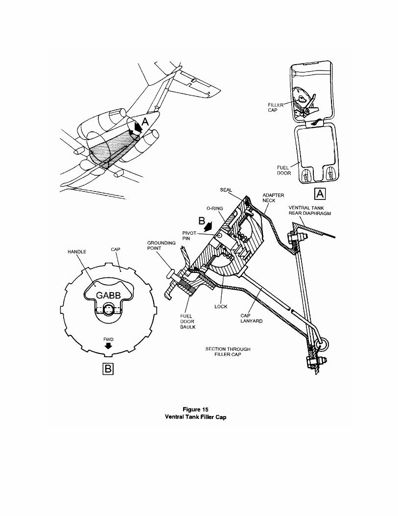
Gravity Refuel Ventral Tank
NOTE: If the ventral tank is to be used in flight it must be full and each wing must contain more than 3450 lb. (1565 kg) of fuel.
NOTE: After refueling the ventral tank to full and after you de-energize and energize the airplane bus bars, the ventral tank indicator may give a cross-hatch "not full" indication due to settling. To confirm that the ventral tank is full, a small amount of fuel can be transferred into the ventral tank.
(1)Use the water drain to drain all the water from the ventral tank.
WARNING: APU MUST NOT BE IN OPERATION.
(2)Energize the DC bus bars (Figure 26).(3)Make sure the VENTRAL tank contents indication is not displaying FULL.(4)Make sure the AUX FUEL TRANSFER valve is shut (lever fully up).(5)Connect the refueling equipment to ground per local procedures (be sure equipment
connections are properly bonded).
NOTE: Observe the local refueling safety instructions.
(6)Open gravity refuel access door in ventral tank rear fairing. Bond filler nozzle to grounding point on tank, remove filler cap from tank and pump fuel into tank until full, remove nozzle.
(7) Make sure the filler cap is operable, install and tighten cap to tank. Disconnect bonding lead and close access door.
(8)Make sure that the VENTRAL tank contents indication is displaying FULL.(9)Disconnect the tanker or hydrant bonding lead.(10) De-energize DC bus bars (Figure 26).(11) Drain water from tanks.(12) Refuel all other tanks as required for flight.
CAUTION: LEAVE THE AUX FUEL TRANSFER VALVE SHUT OR FUEL MAY TRANSFER FROM THE VENTRAL TANK TO THE WING TANKS.
Gravity Defuel Tanks
Equipment Materials Part/Item No.
Gravity refueling drain adapter 25Y867ASuction refueling drain adapter 25Y635A
NOTE: 25Y867A is a sub-assembly of 25Y635A and can be obtained separately.

NOTE: Fuel maybe off-loaded by gravity into a container, or by suction into a tanker or hydrant.
(1) Make sure of the fuel load required.(2) Drain all water from tanks.
NOTE. Observe the local refueling safety precautions.
(3) Bond tanker, hydrant or container to airplane per local refueling procedures.(4) Put a wing skin protection mat on the wing at the filling point for tank being defueled,
unlock and remove filler cap.(5) Remove blanking adapter from fuel drain and install drain adapter to tank. NOTE:
25Y867A is for gravity defueling, 25Y635A is for suction defueling.(6) Off-load fuel as required from each tank.(7) Remove drain adapter and install blanking adapter to fuel drain valve.(8) Install filler cap(s) and lock. Remove wing skin protection mat.