hd standard length sye kit for the np231 - jb … · 2018-01-27 · hd standard length sye kit for...
TRANSCRIPT
1
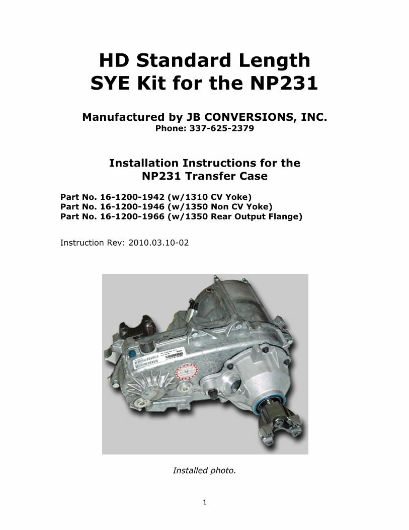
HD Standard Length SYE Kit for the NP231
Manufactured by JB CONVERSIONS, INC. Phone: 337-625-2379
Installation Instructions for the NP231 Transfer Case
Part No. 16-1200-1942 (w/1310 CV Yoke) Part No. 16-1200-1946 (w/1350 Non CV Yoke) Part No. 16-1200-1966 (w/1350 Rear Output Flange)
Instruction Rev: 2010.03.10-02
Installed photo.
2
Applications:
• Use with Jeep NP231J transfer cases in TJ, YJ, and XJ vehicles
• Compatible with GM NP231C & NP233C transfer cases requiring Chrysler type speedometer pickup
• Compatible with Dodge NP231 requiring Chrysler type speedometer pickup
Installation Instructions Note: This kit can be installed without removing the transfer case from the vehicle however it is recommended that the unit be removed to ease installation of the SYE kit.
1) Secure the vehicle and remove the transfer case from the vehicle. Drain the fluid from the case. Remove the rubber boot from the rear bearing housing by prying or cutting the steel band. Remove the front output yoke. A new locknut and rubber "star" washer is included in the kit for reassembly.
2) Remove the dust shield from the mainshaft. This can be easily accomplished by using a chisel to dent the dust shield collar area (where the boot band was located) in two places at 180 degrees apart then prying the shield loose using a screwdriver. Next remove the oil seal from the rear bearing housing.
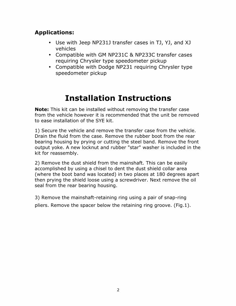
3) Remove the mainshaft-retaining ring using a pair of snap-ring
pliers. Remove the spacer below the retaining ring groove. (Fig.1).
3
FIG: 1
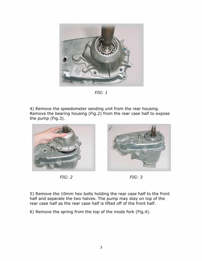
4) Remove the speedometer sending unit from the rear housing. Remove the bearing housing (Fig.2) from the rear case half to expose the pump (Fig.3).
FIG: 2 FIG: 3
5) Remove the 10mm hex bolts holding the rear case half to the front half and separate the two halves. The pump may stay on top of the rear case half as the rear case half is lifted off of the front half.
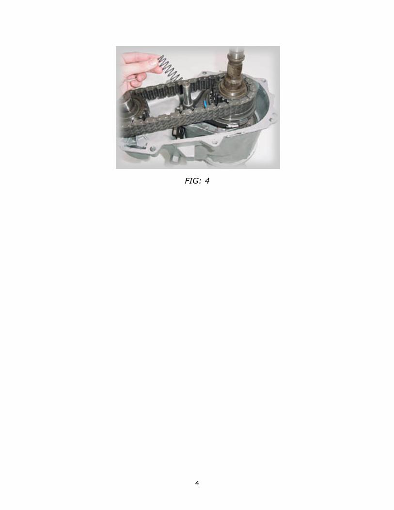
6) Remove the spring from the top of the mode fork (Fig.4).
4
FIG: 4
5
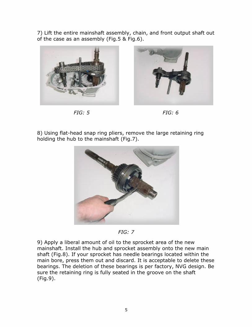
7) Lift the entire mainshaft assembly, chain, and front output shaft out of the case as an assembly (Fig.5 & Fig.6).
FIG: 5 FIG: 6
8) Using flat-head snap ring pliers, remove the large retaining ring holding the hub to the mainshaft (Fig.7).
FIG: 7
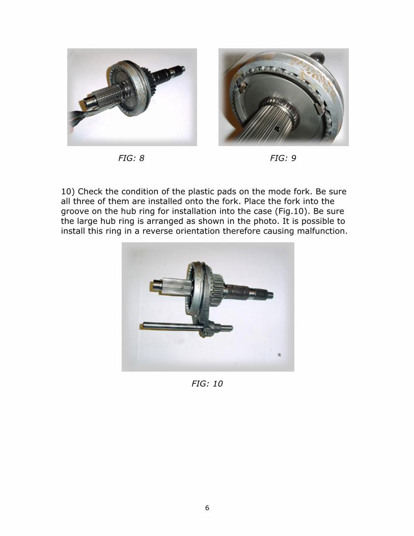
9) Apply a liberal amount of oil to the sprocket area of the new mainshaft. Install the hub and sprocket assembly onto the new main shaft (Fig.8). If your sprocket has needle bearings located within the main bore, press them out and discard. It is acceptable to delete these bearings. The deletion of these bearings is per factory, NVG design. Be sure the retaining ring is fully seated in the groove on the shaft (Fig.9).
6
FIG: 8 FIG: 9
10) Check the condition of the plastic pads on the mode fork. Be sure all three of them are installed onto the fork. Place the fork into the groove on the hub ring for installation into the case (Fig.10). Be sure the large hub ring is arranged as shown in the photo. It is possible to install this ring in a reverse orientation therefore causing malfunction.
FIG: 10
7
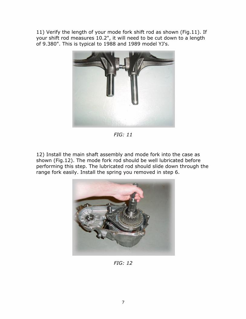
11) Verify the length of your mode fork shift rod as shown (Fig.11). If your shift rod measures 10.2", it will need to be cut down to a length of 9.380". This is typical to 1988 and 1989 model YJ's.
FIG: 11
12) Install the main shaft assembly and mode fork into the case as shown (Fig.12). The mode fork rod should be well lubricated before performing this step. The lubricated rod should slide down through the range fork easily. Install the spring you removed in step 6.
FIG: 12
8
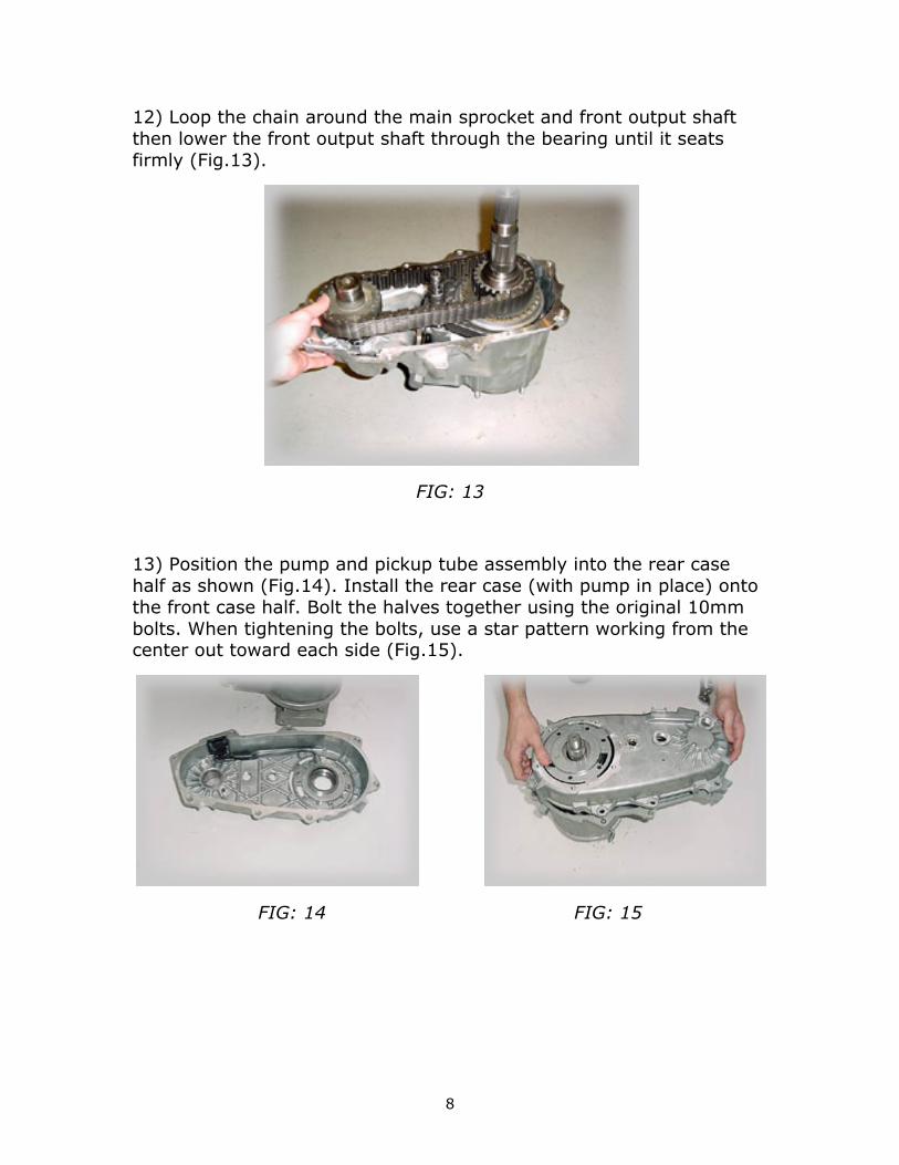
12) Loop the chain around the main sprocket and front output shaft then lower the front output shaft through the bearing until it seats firmly (Fig.13).
FIG: 13
13) Position the pump and pickup tube assembly into the rear case half as shown (Fig.14). Install the rear case (with pump in place) onto the front case half. Bolt the halves together using the original 10mm bolts. When tightening the bolts, use a star pattern working from the center out toward each side (Fig.15).
FIG: 14 FIG: 15
9
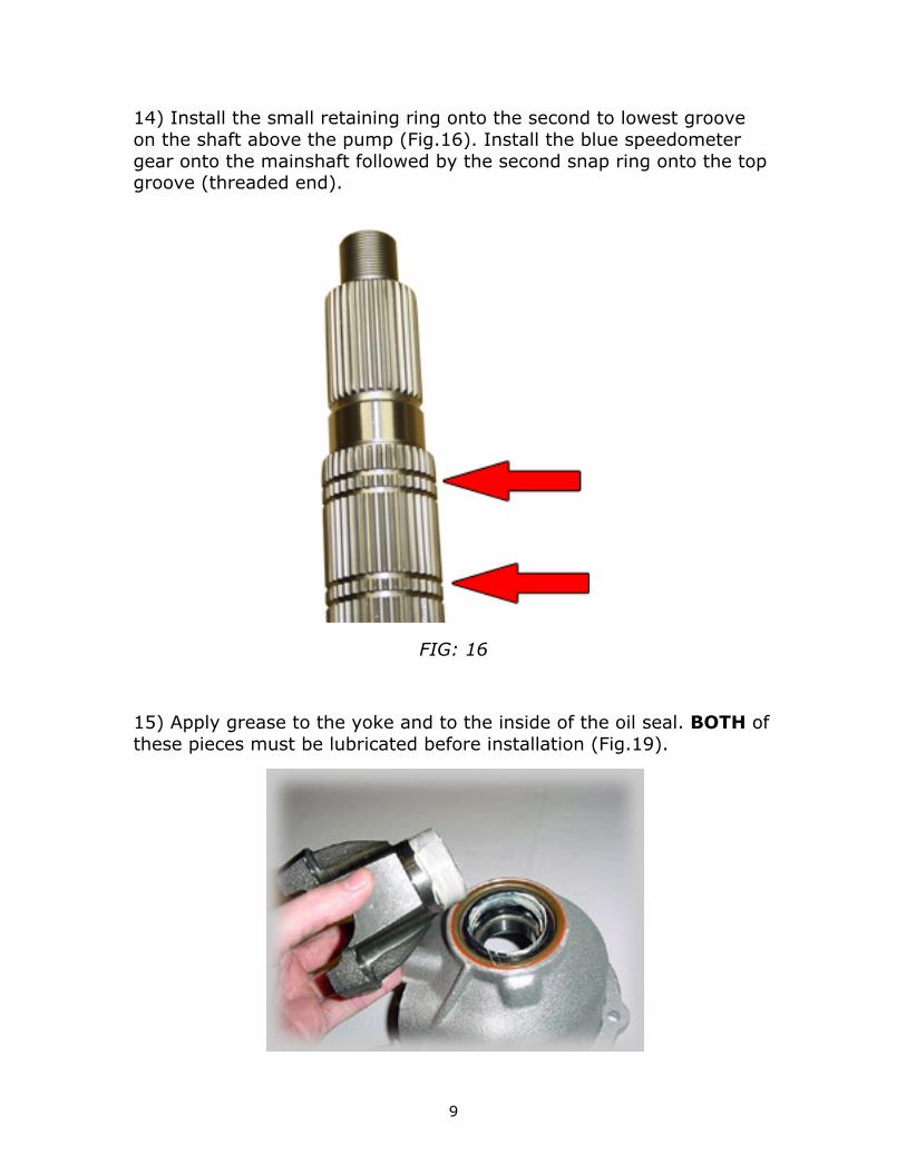
14) Install the small retaining ring onto the second to lowest groove on the shaft above the pump (Fig.16). Install the blue speedometer gear onto the mainshaft followed by the second snap ring onto the top groove (threaded end).
FIG: 16
15) Apply grease to the yoke and to the inside of the oil seal. BOTH of these pieces must be lubricated before installation (Fig.19).
10
FIG: 19
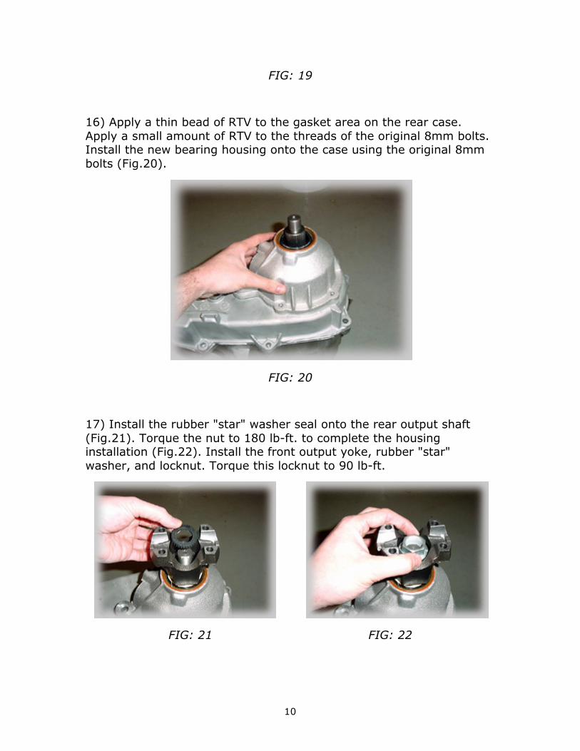
16) Apply a thin bead of RTV to the gasket area on the rear case. Apply a small amount of RTV to the threads of the original 8mm bolts. Install the new bearing housing onto the case using the original 8mm bolts (Fig.20).
FIG: 20
17) Install the rubber "star" washer seal onto the rear output shaft (Fig.21). Torque the nut to 180 lb-ft. to complete the housing installation (Fig.22). Install the front output yoke, rubber "star" washer, and locknut. Torque this locknut to 90 lb-ft.
FIG: 21 FIG: 22
11
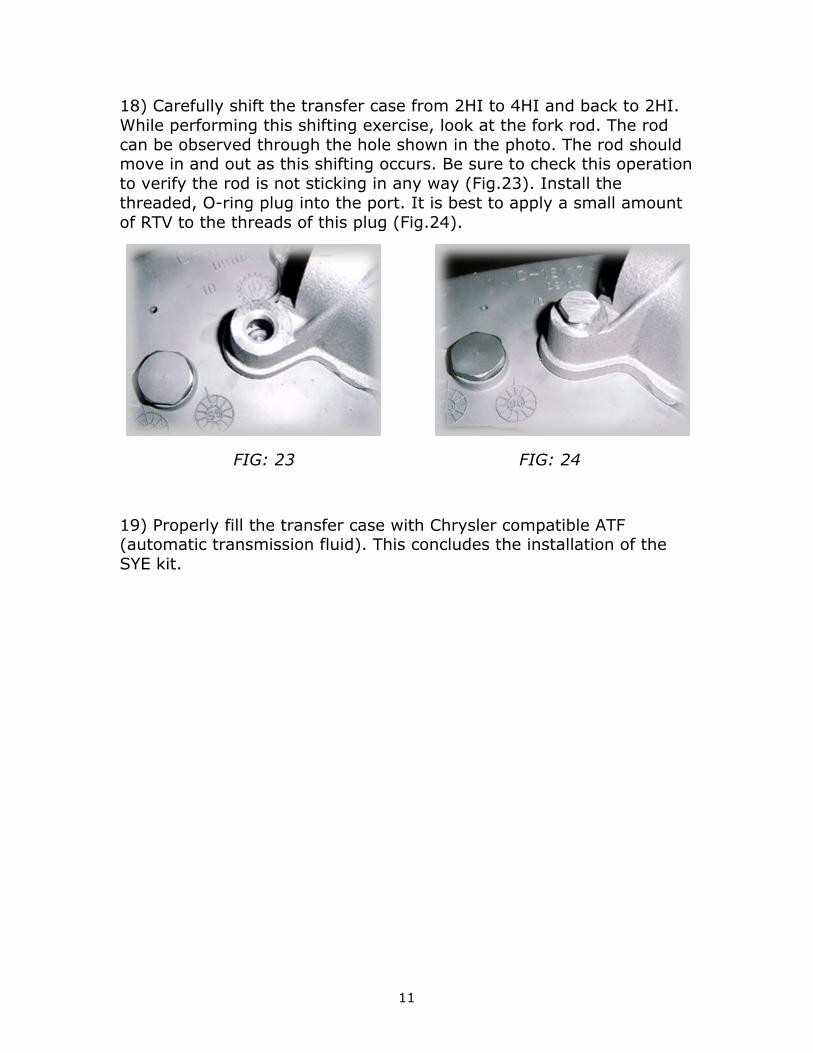
18) Carefully shift the transfer case from 2HI to 4HI and back to 2HI. While performing this shifting exercise, look at the fork rod. The rod can be observed through the hole shown in the photo. The rod should move in and out as this shifting occurs. Be sure to check this operation to verify the rod is not sticking in any way (Fig.23). Install the threaded, O-ring plug into the port. It is best to apply a small amount of RTV to the threads of this plug (Fig.24).
FIG: 23 FIG: 24
19) Properly fill the transfer case with Chrysler compatible ATF (automatic transmission fluid). This concludes the installation of the SYE kit.