hd25000 - texasinternational.com
TRANSCRIPT
HD2500025” (63.5cm) 60K ft-lbsHydraulically Powered Tong
mccoyglobal.com©2010 McCoy Corporation. All rights reserved.Published by McCoy Corporation, Technical Publications Department4225 Hwy 90 East • Broussard, LA USA 70518
Specifications• Operation• Maintenance• Assembly•
TECHNICAL MANUAL

DRI
LLIN
G &
CO
MPL
ETIO
NS
FARR
Section Contentsii
HD25000 25” Tong
Technical Manual

DRI
LLIN
G &
CO
MPL
ETIO
NS
FARR
Section Contents iii Technical Manual
HD25000 25” Tong
This manual covers the following models:
Tong MoDEL REV DESCRIPTIon
80-1903 0 25” Tong c/w Rineer GA125-113 Single Speed motor, chain sling, motor valve & lift valve.
80-1903-1 0 25” Tong c/w Rineer GA125-113 Single Speed motor, chain sling, safety door, motor valve & lift valve.

This page intentionallyleft blank
Section Contentsiv Technical Manual
HD25000 25” Tong
DRI
LLIN
G &
CO
MPL
ETIO
NS
FARR

DRI
LLIN
G &
CO
MPL
ETIO
NS
FARR
Section Contents v Technical Manual
HD25000 25” Tong
WARNINGSThe loAd-beARING devIce SupplIed by FARR cANAdA, A dIvISIoN oF Mccoy coRpoRATIoN (A “loAd-beARING devIce” IS A chAIN SlING, RIGId SlING, SpReAdeR bAR ASSeMbly, FRAMe, oR ANy oTheR devIce ThAT beARS The pARTIAl oR ToTAl WeIGhT oF The equIpMeNT deScRIbed IN ThIS MANuAl) hAS beeN deSIGNed To SuppoRT The equIpMeNT deScRIbed IN ThIS MAN-uAl. FARR cANAdA WIll NoT GuARANTee The AbIlITy oF The loAd-beAR-ING devIce To SuppoRT ANy oTheR pART, ASSeMbly oR coMbINATIoN oF pARTS ANd ASSeMblIeS. FARR cANAdA WIll NoT GuARANTee The AbIlITy oF The loAd-beARING devIce To lIFT The equIpMeNT deScRIbed IN ThIS MANuAl IF TheRe ARe ANy ModIFIcATIoNS To The loAd-beARING devIce, oR ANy AddITIoNS To The equIpMeNT deScRIbed IN ThIS MANuAl ThAT Add WeIGhT To The equIpMeNT, uNleSS SupplIed by FARR cANAdA.
WheN Re-ASSeMblING loAd-beARING devIceS (chAIN SlINGS, RIGId SlINGS, bAcKup leGS, eTc.) NoTe ThAT The ASSocIATed FASTeNeRS MuST be TIGhTeNed To The coRRecT ToRque SpecIFIed FoR ThAT SIZe oF
FASTeNeR (See SecTIoN 4 - oveRhAul).
ANy ReplAceMeNT FASTeNeR (bolTS, NuTS, cAp ScReWS, MAchINe ScReWS, eTc.) uSed duRING MAINTeNANce oR oveRhAul MuST be GRAde
8 oR equIvAleNT uNleSS oTheRWISe SpecIFIed.

This page intentionallyleft blank
Section Contentsvi Technical Manual
HD25000 25” Tong
DRI
LLIN
G &
CO
MPL
ETIO
NS
FARR

DRI
LLIN
G &
CO
MPL
ETIO
NS
FARR
Section Contents vii Technical Manual
HD25000 25” Tong
© Copyright 2010 Farr Canada (A Division Of McCoy Corporation), all rights reserved. This document is the property of Farr Canada and is supplied as reference information for users of our products. This document and the contents within are considered confidential information, not to be disclosed, copied, transmitted, transcribed in any form, or stored on any type of data storage media without the express written consent of Farr Canada.
While continually striving to maintain accuracy, Farr Canada hereby states that the information con-tained in this technical documentation is subject to change without notice. If you feel this document does not meet your needs, please contact our sales office for the most current available documentation for your product.
Summary of Revisionsdate Section page description of Revision
Dec 2009 N/A N/A Intial Release
Aug 2010N/A N/A Revised branding and graphical layout throughout manual
Intro, 6 iii, viii, 6.34, 6.35
Added 80-1903-1 configuration to covered models, added Safety Door Assembly illustration

DRI
LLIN
G &
CO
MPL
ETIO
NS
FARR
Section Contentsviii
HD25000 25” Tong
Technical Manual
Introduction - - - - - - - - - - - - - - - - - - - - - - - - - - - - - - - - - - - - - - - - - - - - - - - - - - - - Section 1 Contact Information - - - - - - - - - - - - - - - - - - - - - - - - - - - - - - - - - - - - - - - - - - - - 1.1 Equipment Specifications - - - - - - - - - - - - - - - - - - - - - - - - - - - - - - - - - - - - - - - - 1.2 Lubricant Specifications - - - - - - - - - - - - - - - - - - - - - - - - - - - - - - - - - - - - - - - - - 1.4Setup & operation- - - - - - - - - - - - - - - - - - - - - - - - - - - - - - - - - - - - - - - - - - - - - - - - Section 2 Sling & Load-Bearing Device Safety - - - - - - - - - - - - - - - - - - - - - - - - - - - - - - - - 2.1 Major Component Identification - - - - - - - - - - - - - - - - - - - - - - - - - - - - - - - - - - - - 2.4 Hydraulic Schematic / Component Identification - - - - - - - - - - - - - - - - - - - - - - - - 2.6 Hydraulic Connections - - - - - - - - - - - - - - - - - - - - - - - - - - - - - - - - - - - - - - - - - - 2.8 Jaw Availability & Installation- - - - - - - - - - - - - - - - - - - - - - - - - - - - - - - - - - - - - - 2.9 Tong Rig-Up & Leveling - - - - - - - - - - - - - - - - - - - - - - - - - - - - - - - - - - - - - - - - - 2.10 System Operation- - - - - - - - - - - - - - - - - - - - - - - - - - - - - - - - - - - - - - - - - - - - - - 2.13 Initial Start-Up & Break In - - - - - - - - - - - - - - - - - - - - - - - - - - - - - - - - - - - - - - 2.13 Valve Operation - - - - - - - - - - - - - - - - - - - - - - - - - - - - - - - - - - - - - - - - - - - - - 2.14 Making Up A Joint- - - - - - - - - - - - - - - - - - - - - - - - - - - - - - - - - - - - - - - - - - - - 2.16 Breaking Out A Joint - - - - - - - - - - - - - - - - - - - - - - - - - - - - - - - - - - - - - - - - - - 2.16 General Comments - - - - - - - - - - - - - - - - - - - - - - - - - - - - - - - - - - - - - - - - - - - 2.16 Cold Weather Operation - - - - - - - - - - - - - - - - - - - - - - - - - - - - - - - - - - - - - - - - - 2.17Maintenance - - - - - - - - - - - - - - - - - - - - - - - - - - - - - - - - - - - - - - - - - - - - - - - - - - - - Section 3 General Maintenance Safety Practices- - - - - - - - - - - - - - - - - - - - - - - - - - - - - - - 3.1 Cleaning - - - - - - - - - - - - - - - - - - - - - - - - - - - - - - - - - - - - - - - - - - - - - - - - - - - - 3.1 Lubrication - - - - - - - - - - - - - - - - - - - - - - - - - - - - - - - - - - - - - - - - - - - - - - - - - - 3.1 Adjustments- - - - - - - - - - - - - - - - - - - - - - - - - - - - - - - - - - - - - - - - - - - - - - - - - - 3.5 Brakeband Adjustments - - - - - - - - - - - - - - - - - - - - - - - - - - - - - - - - - - - - - - - 3.5 Door Adjustments - - - - - - - - - - - - - - - - - - - - - - - - - - - - - - - - - - - - - - - - - - - 3.6 Recommended Periodic Checks - - - - - - - - - - - - - - - - - - - - - - - - - - - - - - - - - - - 3.7 Tong Disassembly - - - - - - - - - - - - - - - - - - - - - - - - - - - - - - - - - - - - - - - - - - - - - 3.7 Tightening Torque Guide - - - - - - - - - - - - - - - - - - - - - - - - - - - - - - - - - - - - - - - - 3.8 Tong Reassembly Procedures- - - - - - - - - - - - - - - - - - - - - - - - - - - - - - - - - - - - - 3.9Troubleshooting - - - - - - - - - - - - - - - - - - - - - - - - - - - - - - - - - - - - - - - - - - - - - - - - - Section 4 Power Unit Pump Makes Excessive Noise - - - - - - - - - - - - - - - - - - - - - - - - - - - - 4.1 Hydraulic System Overheating - - - - - - - - - - - - - - - - - - - - - - - - - - - - - - - - - - - - 4.2 Excessive Wear Of Moving Parts- - - - - - - - - - - - - - - - - - - - - - - - - - - - - - - - - - - 4.3 Tong Running Too Slowly - - - - - - - - - - - - - - - - - - - - - - - - - - - - - - - - - - - - - - - - 4.4 Tong Will Not Develop Sufficient Torque - - - - - - - - - - - - - - - - - - - - - - - - - - - - - 4.5 Failure Of Jaws To Grip Pipe - - - - - - - - - - - - - - - - - - - - - - - - - - - - - - - - - - - - - 4.6 General Comments - - - - - - - - - - - - - - - - - - - - - - - - - - - - - - - - - - - - - - - - - - - - 4.7decomissioning, Storage, And Recomissioning - - - - - - - - - - - - - - - - - - - - - - - - - Section 5Assemblies And parts lists - - - - - - - - - - - - - - - - - - - - - - - - - - - - - - - - - - - - - - - - Section 6 Geartrain Layout - - - - - - - - - - - - - - - - - - - - - - - - - - - - - - - - - - - - - - - - - - - - - - 6.2 Support Roller - - - - - - - - - - - - - - - - - - - - - - - - - - - - - - - - - - - - - - - - - - - - - - - - 6.4 Support Roller - Brakeband - - - - - - - - - - - - - - - - - - - - - - - - - - - - - - - - - - - - - - 6.6 Support Roller - Door - - - - - - - - - - - - - - - - - - - - - - - - - - - - - - - - - - - - - - - - - - - 6.8 Support Roller - Door Pivot - - - - - - - - - - - - - - - - - - - - - - - - - - - - - - - - - - - - - - - 6.10 Rotary Idler - - - - - - - - - - - - - - - - - - - - - - - - - - - - - - - - - - - - - - - - - - - - - - - - - - 6.12 Pinion Idler - - - - - - - - - - - - - - - - - - - - - - - - - - - - - - - - - - - - - - - - - - - - - - - - - - 6.14 Pinion Assembly- - - - - - - - - - - - - - - - - - - - - - - - - - - - - - - - - - - - - - - - - - - - - - - 6.16 Clutch Assembly - - - - - - - - - - - - - - - - - - - - - - - - - - - - - - - - - - - - - - - - - - - - - - 6.18 Cageplate (Rotary) Assembly - - - - - - - - - - - - - - - - - - - - - - - - - - - - - - - - - - - - - 6.20 Tong Body Assembly - - - - - - - - - - - - - - - - - - - - - - - - - - - - - - - - - - - - - - - - - - - 6.22 Tong Body - Hydraulic Assembly - - - - - - - - - - - - - - - - - - - - - - - - - - - - - - - - - - - 6.24 Shifter Assembly - - - - - - - - - - - - - - - - - - - - - - - - - - - - - - - - - - - - - - - - - - - - - - 6.26 Chain Sling - - - - - - - - - - - - - - - - - - - - - - - - - - - - - - - - - - - - - - - - - - - - - - - - - - 6.28 Tong Door Assembly - - - - - - - - - - - - - - - - - - - - - - - - - - - - - - - - - - - - - - - - - - - 6.30 Door Latch Assembly - - - - - - - - - - - - - - - - - - - - - - - - - - - - - - - - - - - - - - - - - - - 6.32 Safety Door Assembly - - - - - - - - - - - - - - - - - - - - - - - - - - - - - - - - - - - - - - - - - - 6.34Torque Measurement Section - - - - - - - - - - - - - - - - - - - - - - - - - - - - - - - - - - - - - - - Section 7 Load Cell Assembly - - - - - - - - - - - - - - - - - - - - - - - - - - - - - - - - - - - - - - - - - - - - 7.2 Trouble Shooting - - - - - - - - - - - - - - - - - - - - - - - - - - - - - - - - - - - - - - - - - - - - - - 7.4 Periodic Inspection and Maintenance- - - - - - - - - - - - - - - - - - - - - - - - - - - - - - - - 7.5

DRI
LLIN
G &
CO
MPL
ETIO
NS
FARR
Section Contents ix Technical Manual
HD25000 25” Tong
hydraulic Section - - - - - - - - - - - - - - - - - - - - - - - - - - - - - - - - - - - - - - - - - - - - - - - - Section 8 Staffa HMB Hydraulic Motor Information- - - - - - - - - - - - - - - - - - - - - - - - - - - - - - 8.1 Hydraulic Valve Information- - - - - - - - - - - - - - - - - - - - - - - - - - - - - - - - - - - - - - - 8.12daily Tong Inspection And Maintenance. . . . . . . . . . . . . . . . . . . . . . . . . . . . . . . . . . Appendix oneMonthly Tong Maintenance checklist . . . . . . . . . . . . . . . . . . . . . . . . . . . . . . . . . . . . Appendix Two
Critical Warning!Standard Warning*
Alert
IdeNTIFIcATIoN oF WARNINGS ANd oTheR NoMeNclATuRe oF IMpoRTANce uSed IN ThIS MANuAl
Farr Canada uses three subsets to describe items in three degrees of importance.
The highest level of urgency is called a cRITIcAl WARNING, and is identified with an exclamation point, is red in color, and is surrounded by a double black box. A cRITIcAl WARNING denotes an item of extreme importance, and failure to heed a cRITIcAl WARNING may result in bodily injury, death, severe equipment damage, or any combination of these.
A STANdARd WARNING is identified with an asterisk, and contains information critical to the correct as-sembly or operation of the unit. A STANdARd WARNING may also serve to alert the user to a potential low-level injury hazard. A STANdARd WARNING is also surrounded by a double black box, but is amber in colour.
An AleRT is identified by black text within a double black box. An AleRT contains specific information of note that pertains to the correct assembly or operation of the unit.

This page intentionallyleft blank
Section Contentsx Technical Manual
HD25000 25” Tong
DRI
LLIN
G &
CO
MPL
ETIO
NS
FARR

DRI
LLIN
G &
CO
MPL
ETIO
NS
FARR
Section Contents 1.1 Technical Manual
HD25000 25” Tong
Congratulations on the purchase of your new Farr Canada tong. This unit will provide you with years of outstanding perfor-mance. Simple maintenance and care will extend its life and ensure continuing excellent performance and reliability.
This manual will assist you in giving your equipment the care it requires. Please read the manual and follow the enclosed maintenance instructions. Replacement parts are readily available from FARR Canada Ltd. in Edmonton, Alberta. However, most of the parts that are subject to wear or damage are standard items likely to be found in supply stores or parts depots. Many parts are transferable between FARR tongs and backups.
Should you need replacement parts, or should you experience any difficulty not covered in this manual, please contact:
Mccoy drilling & completions | FARRSales & engineering14755 121A AvenueEdmonton, AlbertaCanada T5L 2T2
Phone: 780.453.3277Fax: 780.455.2432
Email Sales: [email protected] Email Engineering: [email protected]
Website: http://www.mccoyglobal.com

DRI
LLIN
G &
CO
MPL
ETIO
NS
FARR
Section Contents1.2
HD25000 25” Tong
Technical Manual
SPECIfICaTIonS - EquIPMEnT
89.4”
56.9
”
78.2
”
25.3
”
DRI
LLIN
G &
CO
MPL
ETIO
NS
FARR
Section Contents 1.3 Technical Manual
HD25000 25” TongSPECIfICaTIonS - EquIPMEnT
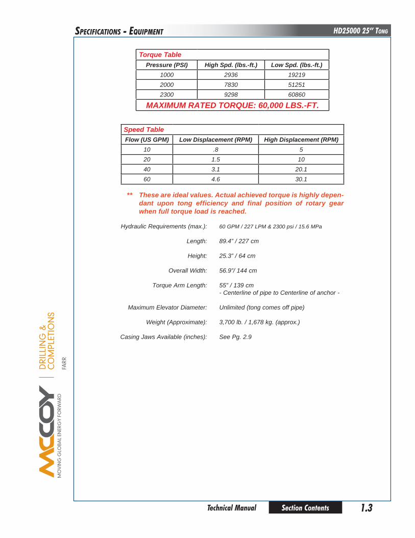
Hydraulic Requirements (max.): 60 GPM / 227 LPM & 2300 psi / 15.6 MPa Length: 89.4” / 227 cm
Height: 25.3” / 64 cm
Overall Width: 56.9”/ 144 cm
Torque Arm Length: 55” / 139 cm - Centerline of pipe to Centerline of anchor -
Maximum Elevator Diameter: Unlimited (tong comes off pipe) Weight (Approximate): 3,700 lb. / 1,678 kg. (approx.)
Casing Jaws Available (inches): See Pg. 2.9
Torque Tablepressure (pSI) high Spd. (lbs.-ft.) low Spd. (lbs.-ft.)
1000 2936 192192000 7830 512512300 9298 60860
MAXIMuM RATed ToRque: 60,000 lbS.-FT.
Speed TableFlow (uS GpM) low displacement (RpM) high displacement (RpM)
10 .8 520 1.5 1040 3.1 20.160 4.6 30.1
** These are ideal values. Actual achieved torque is highly depen-dant upon tong efficiency and final position of rotary gear when full torque load is reached.
DRI
LLIN
G &
CO
MPL
ETIO
NS
FARR
Section Contents1.4
HD25000 25” Tong
Technical Manual
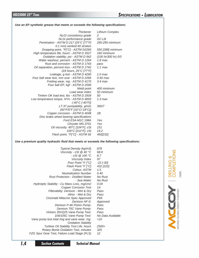
use an ep synthetic grease that meets or exceeds the following specifications: Thickener Lithium Complex NLGI consistency grade 2 NLGI performance grade GC-LB Penetration - ASTM D 217 (25°C [77°F] 265-295 minimum 0.1 mm) worked 60 strokes Dropping point, °F[°C] - ASTM D2265 550 [288] minimum High temperature life, hours - ASTM D 3527 160 minimum Oxidation stability, psi - ASTM D 942 (100 hr/300 hr) 0/3 Water washout, percent - ASTM D 1264 1.8 max Rust and corrosion - ASTM D 1743 pass Oil separation, percent loss - ASTM D 1742 1.1 max (24 hours, 25°C [77°F] Leakage, g lost - ASTM D 4290 1.0 max Four ball wear test, mm scar - ASTM D 2266 0.40 max Fretting wear, mg - ASTM D 4170 3.4 max Four ball EP, kgf - ASTM D 2596 Weld point 400 minimum Load wear index 50 minimum Timken OK load test, lbs - ASTM D 2509 50 Low temperature torque, N*m - ASTM D 4693 1.3 max (-40°C [-40°F]) LT-37 pumpability, g/min 360/7 (60°F/0°F [16°C/-18°C]) Copper corrosion - ASTM D 4048 1B Disc brake wheel bearing specifications Ford ESA-M1C 198A Yes Chrysler MS-3701 Yes Oil viscosity: 40°C [104°F], cSt 151 100°C [212°F], cSt 19.2 Flash point, °F[°C] - ASTM 92 450[232]
use a premium quality hydraulic fluid that meets or exceeds the following specifications: Typical Density (kg/m3) 878 Viscosity - cSt @ 40 °C 68.8 - cSt @ 100 °C 8.7 Viscosity Index 97 Pour Point °F [°C] -22 [-30] Flash Point °F [°C] 432 [222] Colour, ASTM 1.5 Neutralization Number 0.40 Rust Protection - Distilled Water No Rust - Sea Water No Rust Hydrolytic Stability - Cu Mass Loss, mg/cm2 0.04 Copper Corrosion Test 1A Filterability: Denison - Wet & Dry Pass Afnor - Wet & Dry Pass Cincinatti Milacron Spec Approved P69 Denison HF-0: Approved Denison P-46 Piston Pump: Pass Denison T6C Vane Pump: Pass Vickers 35VQ25 Vane Pump Test: Pass 104/105C Vane Pump Test: No Data Available Vane pump test total ring and vane wear, mg. <10 Oxidation Stability Turbine Oil Stability Test Life, hours 2500+ Rotary Bomb Oxidation Test, minutes 325 FZG Spur Gear Test, Failure Load Stage (FLS) 12
SPECIfICaTIonS - LubRICaTIon

DRI
LLIN
G &
CO
MPL
ETIO
NS
FARR
Section Contents 2.1 Technical Manual
HD25000 25” TongSETuP & oPERaTIon
Adequate setup and proper hydraulic connections are essential in ensuring reliable operation of your tong. For best results and long term reliability, read and obey the start-up instructions in this section.
A. SlING / loAd beARING devIce SAFeTy
A “loAd-beARING devIce” IS A chAIN SlING, RIGId SlING, SpReAdeR bAR AS-SeMbly, FRAMe, oR ANy oTheR devIce ThAT beARS The pARTIAl oR ToTAl WeIGhT oF The equIpMeNT deScRIbed IN ThIS MANuAl.
The SupplIed loAd-beARING devIce hAS beeN SpecIFIed oR deSIGNed To SuppoRT The equIpMeNT deScRIbed IN ThIS MANuAl. FARR cANAdA WIll NoT GuARANTee The AbIlITy oF The loAd-beARING devIce To SuppoRT ANy oTheR pART, ASSeMbly oR coMbINATIoN oF pARTS ANd ASSeMblIeS, oR ANy AddI-TIoNS To The equIpMeNT deScRIbed IN ThIS MANuAl ThAT Add WeIGhT To The equIpMeNT, uNleSS SupplIed by FARR cANAdA.
FARR cANAdA WIll NoT GuARANTee The INTeGRITy oF ModIFIed oR dAMAGed loAd-beARING devIceS, uNleSS ThoSe ModIFIcATIoNS ARe peRFoRMed by FARR cANAdA.
!
Farr Canada recommends following an industry-accepted standard such as OSHA, ASME B30.9-2006, or manufacturer’s guidelines when performing any rigging and overhead lifting. Use by untrained persons is hazardous. Improper use will result in serious injury or death. Do not exceed rated capacity. Slings will fail if damaged, abused, misused, overused, or improperly maintained.
• Onlygrade80orgrade100alloychainshouldbeusedforoverheadliftingapplications.• WorkingLoadLimit(WLL)isthemaximumallowableloadinpoundswhichmaybeappliedtotheload-bearing
device, when the device is new or in “as new” condition, and when the load is uniformly and directly applied. The WLL must never be exceeded.
• WorkingLoadLimit(WLL)isthemaximumworkingloadforaspecificminimumslingangle,measuredfromthehorizontal plane. The Working Load Limit is identified on the sling.
• TheWorkingLoadLimitorDesignfactormaybeaffectedbywear,misuse,overloading,corrosion,deformation,intentional alterations, sharp corner cutting action and other use conditions.
• Shockloadingandextraordinaryconditionsmustbetakenintoaccountwhenselectingalloychainslings.• SeeOSHARegulation forSlings1910.184,ANSI/ASMEB30.9-”SLINGS”,ANSI/ASMEB30.10-”HOOKS”and
ANSI/AMSE B30.26 “RIGGING HARDWARE” for additional information.
The MINIMuM SlING ANGle (The ANGle oF The leG oF The SlING MeASuRed FRoM The hoRIZoNTAl) MuST NeveR FAll loWeR ThAN The ANGle SpecIFIed
FoR The SlING IN uSe!
Sling Angle
DRI
LLIN
G &
CO
MPL
ETIO
NS
FARR
Section Contents2.2
HD25000 25” Tong
Technical Manual
1. Inspection Of Slings
Farr canada strongly recommends the following practices:
A complete inspection of new load-bearing devices and attachments shall be performed by a qualified, designated per-son prior to initial use. Each link and component shall be examined individually, taking care to expose and examine all surfaces including the inner link surface. The sling shall be examined for conditions such as those listed in the removal criteria below. In addition, daily inspection of slings, fastenings and attachments shall be performed by a designated person. If damage or defects are found at either inspection, the damaged or defective component shall be quarantined from service until it can be properly repaired or replaced.
Removal Criteria:
A load-bearing device shall be removed from service if conditions such as the following are present:
• Missingorillegibleslingidentification.• Cracksorbreaks• Evidenceof tampering isseen-slingtaghasbeenmodifiedorobscured,or tamper-proofnutsaremiss-
ing.• Signsofimpactonload-bearingcomponents,includingspreaderbars,liftinglugs,rigidslings&rigidsling
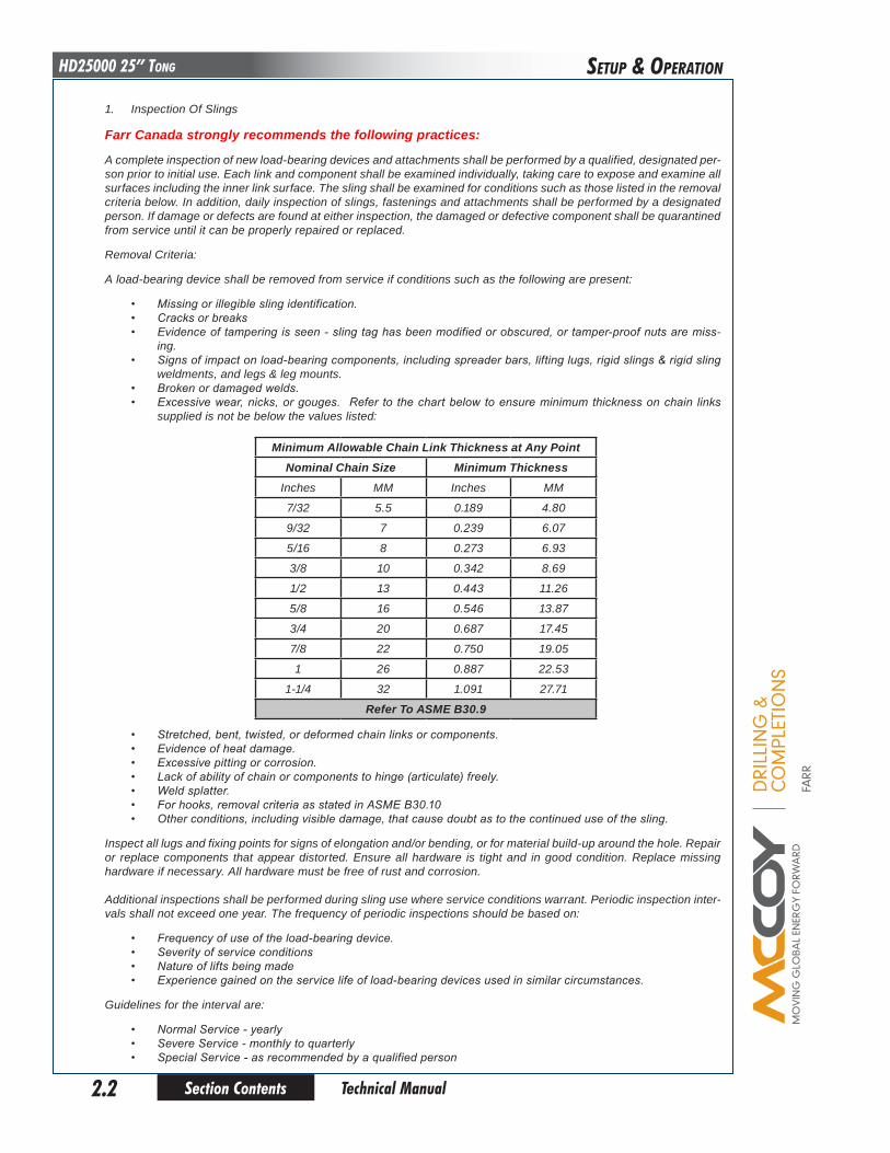
weldments, and legs & leg mounts.• Brokenordamagedwelds.• Excessivewear,nicks,orgouges. Refer to thechartbelow toensureminimumthicknessonchain links
supplied is not be below the values listed:
Minimum Allowable chain link Thickness at Any pointNominal chain Size Minimum Thickness
Inches MM Inches MM
7/32 5.5 0.189 4.80
9/32 7 0.239 6.07
5/16 8 0.273 6.93
3/8 10 0.342 8.69
1/2 13 0.443 11.26
5/8 16 0.546 13.87
3/4 20 0.687 17.45
7/8 22 0.750 19.05
1 26 0.887 22.53
1-1/4 32 1.091 27.71
Refer To ASMe b30.9
• Stretched,bent,twisted,ordeformedchainlinksorcomponents.• Evidenceofheatdamage.• Excessivepittingorcorrosion.• Lackofabilityofchainorcomponentstohinge(articulate)freely.• Weldsplatter.• Forhooks,removalcriteriaasstatedinASMEB30.10• Otherconditions,includingvisibledamage,thatcausedoubtastothecontinueduseofthesling.
Inspect all lugs and fixing points for signs of elongation and/or bending, or for material build-up around the hole. Repair or replace components that appear distorted. Ensure all hardware is tight and in good condition. Replace missing hardware if necessary. All hardware must be free of rust and corrosion.
Additional inspections shall be performed during sling use where service conditions warrant. Periodic inspection inter-vals shall not exceed one year. The frequency of periodic inspections should be based on:
• Frequencyofuseoftheload-bearingdevice.• Severityofserviceconditions• Natureofliftsbeingmade• Experiencegainedontheservicelifeofload-bearingdevicesusedinsimilarcircumstances.
Guidelines for the interval are:
• NormalService-yearly• SevereService-monthlytoquarterly• SpecialService-asrecommendedbyaqualifiedperson
SETuP & oPERaTIon
DRI
LLIN
G &
CO
MPL
ETIO
NS
FARR
Section Contents 2.3 Technical Manual
HD25000 25” Tong
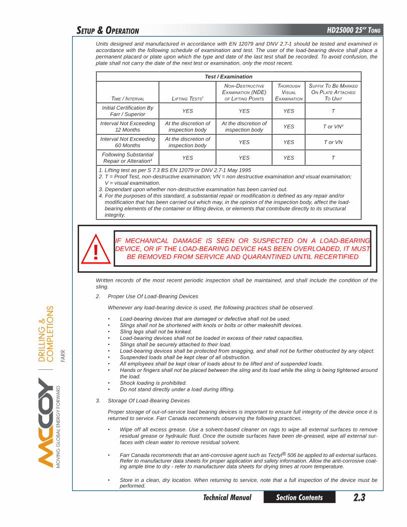
Units designed and manufactured in accordance with EN 12079 and DNV 2.7-1 should be tested and examined in accordance with the following schedule of examination and test. The user of the load-bearing device shall place a permanent placard or plate upon which the type and date of the last test shall be recorded. To avoid confusion, the plate shall not carry the date of the next test or examination, only the most recent.
Test / examination
Time / inTerval lifTing TesTs1
non-DesTrucTive examinaTion (nDe)
of lifTing PoinTs
Thorough visual
examinaTion
suffix To Be markeD on PlaTe aTTacheD
To uniT
Initial Certification By Farr / Superior YES YES YES T
Interval Not Exceeding 12 Months
At the discretion of inspection body
At the discretion of inspection body YES T or VN3
Interval Not Exceeding 60 Months
At the discretion of inspection body YES YES T or VN
Following Substantial Repair or Alteration4 YES YES YES T
1. Lifting test as per S 7.3 BS EN 12079 or DNV 2.7-1 May 19952. T = Proof Test, non-destructive examination; VN = non destructive examination and visual examination; V = visual examination.3. Dependant upon whether non-destructive examination has been carried out.4. For the purposes of this standard, a substantial repair or modification is defined as any repair and/or modification that has been carried out which may, in the opinion of the inspection body, affect the load- bearing elements of the container or lifting device, or elements that contribute directly to its structural integrity.
IF MECHANICAL DAMAGE IS SEEN OR SUSPECTED ON A LOAD-BEARING DEVICE, OR IF THE LOAD-BEARING DEVICE HAS BEEN OVERLOADED, IT MUST
BE REMOVED FROM SERVICE AND QUARANTINED UNTIL RECERTIFIED!Written records of the most recent periodic inspection shall be maintained, and shall include the condition of the sling.
2. Proper Use Of Load-Bearing Devices
Whenever any load-bearing device is used, the following practices shall be observed.
• Load-bearingdevicesthataredamagedordefectiveshallnotbeused.• Slingsshallnotbeshortenedwithknotsorboltsorothermakeshiftdevices.• Slinglegsshallnotbekinked.• Load-bearingdevicesshallnotbeloadedinexcessoftheirratedcapacities.• Slingsshallbesecurelyattachedtotheirload.• Load-bearingdevicesshallbeprotectedfromsnagging,andshallnotbefurtherobstructedbyanyobject.• Suspendedloadsshallbekeptclearofallobstruction.• Allemployeesshallbekeptclearofloadsabouttobeliftedandofsuspendedloads.• Handsorfingersshallnotbeplacedbetweentheslinganditsloadwhiletheslingisbeingtightenedaround
the load.• Shockloadingisprohibited.• Donotstanddirectlyunderaloadduringlifting.
3. Storage Of Load-Bearing Devices
Proper storage of out-of-service load bearing devices is important to ensure full integrity of the device once it is returned to service. Farr Canada recommends observing the following practices.
• Wipe off all excess grease. Use a solvent-based cleaner on rags to wipe all external surfaces to remove residual grease or hydraulic fluid. Once the outside surfaces have been de-greased, wipe all external sur-faces with clean water to remove residual solvent.
• Farr Canada recommends that an anti-corrosive agent such as Tectyl® 506 be applied to all external surfaces. Refer to manufacturer data sheets for proper application and safety information. Allow the anti-corrosive coat-ing ample time to dry - refer to manufacturer data sheets for drying times at room temperature.
• Store in a clean, dry location. When returning to service, note that a full inspection of the device must be performed.
SETuP & oPERaTIon

DRI
LLIN
G &
CO
MPL
ETIO
NS
FARR
Section Contents2.4
HD25000 25” Tong
Technical Manual
b. MAJoR coMpoNeNT IdeNTIFIcATIoN
SETuP & oPERaTIon
12
3
4 5 6 7
8
910

DRI
LLIN
G &
CO
MPL
ETIO
NS
FARR
Section Contents 2.5 Technical Manual
HD25000 25” TongSETuP & oPERaTIon
Item description page1 RH Door Assembly 2.4
2 Tong Door Cylinder 2.4
3 Chain Sling Assembly 2.4
4 RH Door Handle 2.4
5 LH Door Handle 2.4
6 LH Door Assembly 2.4
7 Tong Leg 2.4
8 Brakeband Adjustment Assembly 2.4
9 Backing Pin (Shown in Break Out position) 2.4
10 Brakeband 2.4
11 Cageplate Assembly 2.5
12 Hydraulic Inlet Fitting (1”) 2.5
13 Hydraulic Outlet Fitting (1-1/4”) 2.5
14 Hydraulic Valve Bank 2.5
15 Motor Mount 2.5
16 Rineer GA125-113 Hydraulic Motor 2.5
17 3000 psi Pressure Gauge 2.5
18 High / Low Gear Shifter 2.5
19 Torque Gauge Mount 2.5
20 Tension Load Cell Mount 2.5
11 12 2013 14 15 16 17 18 19
DRI
LLIN
G &
CO
MPL
ETIO
NS
FARR
Section Contents2.6
HD25000 25” Tong
Technical Manual
SETuP & oPERaTIon
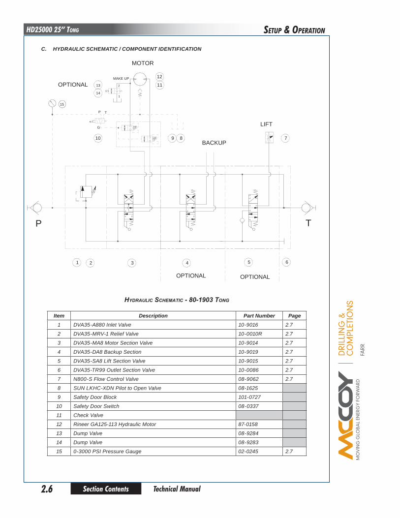
c. hydRAulIc ScheMATIc / coMpoNeNT IdeNTIFIcATIoN
1 432 6
7
P T
5
9 810
12
11
OPTIONAL OPTIONAL
MOTOR
BACKUP
LIFTG
P T
MAKE UP
13
14
2
1
OPTIONAL
15
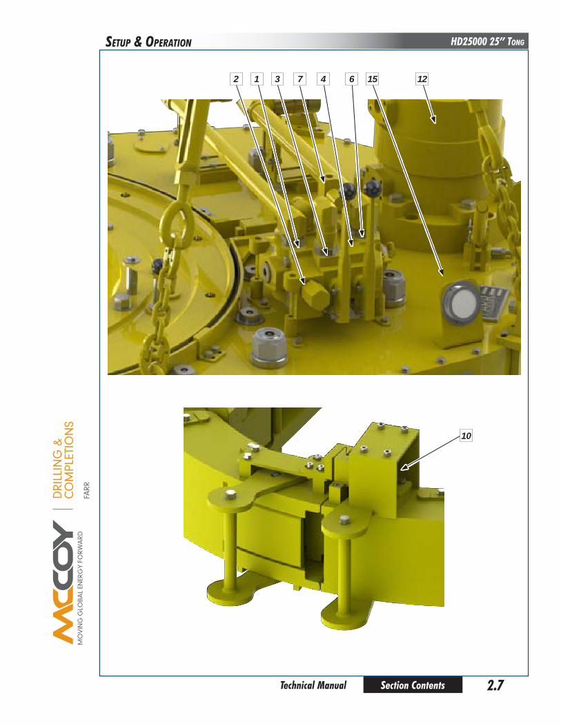
Item description part Number page1 DVA35-A880 Inlet Valve 10-9016 2.7
2 DVA35-MRV-1 Relief Valve 10-0010R 2.7
3 DVA35-MA8 Motor Section Valve 10-9014 2.7
4 DVA35-DA8 Backup Section 10-9019 2.7
5 DVA35-SA8 Lift Section Valve 10-9015 2.7
6 DVA35-TR99 Outlet Section Valve 10-0086 2.7
7 N800-S Flow Control Valve 08-9062 2.7
8 SUN LKHC-XDN Pilot to Open Valve 08-1625
9 Safety Door Block 101-0727
10 Safety Door Switch 08-0337
11 Check Valve
12 Rineer GA125-113 Hydraulic Motor 87-0158
13 Dump Valve 08-9284
14 Dump Valve 08-9283
15 0-3000 PSI Pressure Gauge 02-0245 2.7
Hydraulic ScHematic - 80-1903 tong
DRI
LLIN
G &
CO
MPL
ETIO
NS
FARR
Section Contents 2.7 Technical Manual
HD25000 25” TongSETuP & oPERaTIon
12 3 47 6 1215
10

DRI
LLIN
G &
CO
MPL
ETIO
NS
FARR
Section Contents2.8
HD25000 25” Tong
Technical Manual
d. hydRAulIc coNNecTIoNS
A pair of hydraulic lines - a 1” supply line and a 1-1/4” return line - connect the hydraulic pedestal to the power unit (see illustration below). To minimize the risk of injury perform hydraulic connections when the power unit is not running, or when the hydraulic pump is disengaged. The possibility of error in inter-changing the high pressure supply hose and the low pressure return hose has been eliminated, because the supply side coupling is smaller than the return side. These hose couplings are self-sealing, and care should be taken to ensure complete engagement to prevent partial closure of the check valve in the coupling. Ensure that the nut (female) side is completely made up onto the male connector - there is a line on the male fitting that indicates complete make-up. Snug the female fitting right up to the line.
SETuP & oPERaTIon
1” Supply connection
1-1/4” Return connection
DRI
LLIN
G &
CO
MPL
ETIO
NS
FARR
Section Contents 2.9 Technical Manual
HD25000 25” TongSETuP & oPERaTIon
description part Number9-5/8” Jaw Die Kit 1482-JDK-540
10-3/4” Jaw Die Kit 1482-JDK-545
11-3/4” Jaw Die Kit 1482-JDK-550
13-3/8” Jaw Die Kit 1482-JDK-558
13-1/2” Jaw Die Kit 1482-JDK-559
13-5/8” Jaw Die Kit 1482-JDK-561
14” Jaw Die Kit 1482-JDK-560
16” Jaw Die Kit 1482-JDK-565
18” Jaw Die Kit 1482-JDK-568
18-5/8” Jaw Die Kit 1482-JDK-570
18-3/4” Jaw Die Kit 1482-JDK-571
19-1/2” Jaw Die Kit 1482-JDK-573
20” Jaw Die Kit 1482-JDK-575
22” Jaw Die Kit 1482-JDK-580
24” Jaw Die Kit 1482-JDK-585
24-1/2” Jaw Die Kit 1482-JDK-587
25” Jaw Die Kit 1482-JDK-590
26” Jaw Die Kit 1482-JDK-595
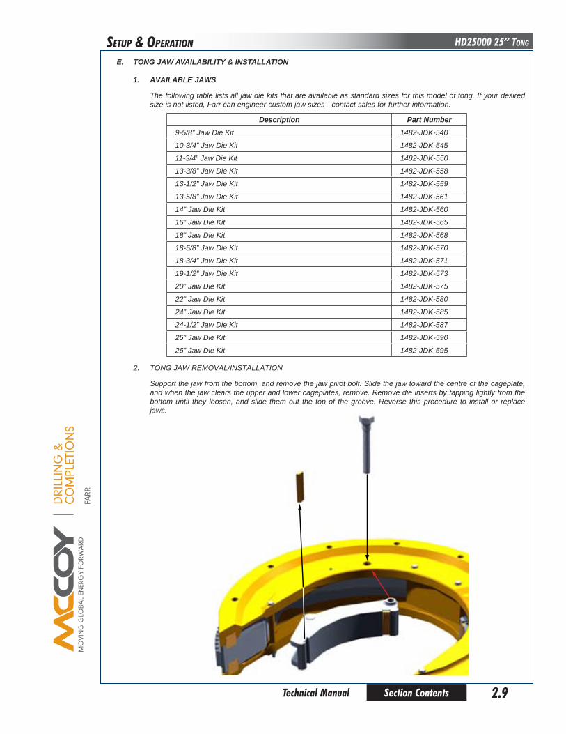
e. ToNG JAW AvAIlAbIlITy & INSTAllATIoN
1. AvAIlAble JAWS
The following table lists all jaw die kits that are available as standard sizes for this model of tong. If your desired size is not listed, Farr can engineer custom jaw sizes - contact sales for further information.
2. TONG JAW REMOVAL/INSTALLATION
Support the jaw from the bottom, and remove the jaw pivot bolt. Slide the jaw toward the centre of the cageplate, and when the jaw clears the upper and lower cageplates, remove. Remove die inserts by tapping lightly from the bottom until they loosen, and slide them out the top of the groove. Reverse this procedure to install or replace jaws.

DRI
LLIN
G &
CO
MPL
ETIO
NS
FARR
Section Contents2.10
HD25000 25” Tong
Technical Manual
SETuP & oPERaTIon
F. TONG RIG-UP & LEVELING 1. Suspension & Load Cell Tie-Off
The tong should be suspended by wire rope of sufficient strength to suspend the entire weight of the tong (XXXX lbs. / XXXX kg.) with a minimum 10% safety margin, and from a location in the derrick high enough to assure easy handling and maneuvering of the tong. The hand line should be placed in a position as near the center of the rotary as possible without interfering with the move-ment of the hoisting equipment. This line may either be extended over a pulley and balanced by a counterweight equal to the weight of the tong (approximately XXXX - XXXX lbs.) or simply tied off in the derrick to form a dead line. In cases where the dead line arrangement is used, it is necessary to use a FARR spring hanger assembly. This spring hanger allows the tong to compensate for the downward movement of the casing as the thread is made-up.
Farr Canada recommends using a backup line of of sufficient strength to withstand the maximum applied torque of the tong (XXXXX lbs.-ft.) plus a 10% safety margin. It must be securely connected to the load cell at the rear of the tong, and tied off to a suitable anchor. To ensure accurate torque measurement, the backup line must be connected perpendicular to the lengthwise axis of the tong, and perpendicular to the hang line (see illustrations below and next page).
90o

DRI
LLIN
G &
CO
MPL
ETIO
NS
FARR
Section Contents 2.11 Technical Manual
HD25000 25” TongSETuP & oPERaTIon
2. Tong Leveling
Assure all turn buckles are fully tightened. Next, place a 4’ level on the tong to determine which of the four mounting points is lowest. When the lowest mounting point is determined, adjust the chain for the mounting point directly opposite the lowest until the two are level. Using the same level, find the next lowest mounting point and adjust (by lowering) the chain until the mounting point is level with the previously adjusted points. After these three points are level, adjust (by lowering) the final chain until the fourth mounting point levels the tong. Once complete, verify with 4’ level.
90o

This page intentionallyleft blank
Section Contents2.12 Technical Manual
HD25000 25” Tong
DRI
LLIN
G &
CO
MPL
ETIO
NS
FARR
SETuP & oPERaTIon
DRI
LLIN
G &
CO
MPL
ETIO
NS
FARR
Section Contents 2.13 Technical Manual
HD25000 25” TongSETuP & oPERaTIon
G. SySTeM opeRATIoN
1. INITIAL START UP & BREAK-IN PROCEDURE
AlThouGh youR NeW equIpMeNT hAS beeN TeSTed ANd INSpecTed AT The FARR FAcToRy pRIoR To ShIppING, We AdvISe ThoRouGh
TeSTING oF youR NeW ToNG AFTeR you TAKeN poSeSSIoN IN oRdeR To elIMINATe The poSSIbIlITy oF ShIppING dAMAGe.
Ensure correct and secure connectons of all hydraulic hoses. Secure all electrical lines to their appropriate connec-tions.
Ensure adequate lube oil and hydraulic oil levels before starting power unit. Use start up procedures as recommended by the power unit engine operator’s manual. Open the Bypass Valve on the hydraulic system, and inspect all pressure and return line hose connections to ensure correct and secure installation. Perform a “walk-around” of the unit to ensure unobstructed operation, and check for hydraulic leaks or any equipment abnormalities.
bAcKup ANd ToNG dooRS MuST be SecuRely cloSed beFoRe The poWeR uNIT IS STARTed IN oRdeR To ASSuRe The SAFeTy
oF opeRATING peRSoNNel!
IMpRopeRly SecuRed hydRAulIc coNNecTIoNS WIll INTeRRupT hydRAulIc FluId FloW, ANd could ReSulT IN The FolloWING
FAIluReS:
•Arestrictioninthepressuresupplyhosewillresultinhighpressurewithinthe power unit hydraulic system, which will activate the hydraulic governor and increase the engine speed to as high as maximum RPM.
•Arestrictioninthereturnlinewillresultinhighpressurewithinthepowerunitand the tong hydraulic system, causing engine speeds as high as maximum RPM, and possible failure of the motor seal.
Following inspection of the hoses, start the engine and allow it to idle until warm. Allow hydraulic fluid to circulate for approximately 10 minutes, then slowly close the Bypass Valve on the power unit to allow hydraulic fluid to circulate through the hoses and to the tong (circulating pressure should not exceed 200 psi). Note that attempting to operate the system with cold hydraulic fluid may affect the way the sequence valves in your system function.
Place the tong gear shifter in low gear. Rotate the tong slowly forward and then reverse with the throttle valve control lever. Once this has been done and the proper size jaws have been installed, the tong is then ready to run pipe.
Farr recommends that the following pre-operating tests be performed prior to releasing the tong assembly to a operational environment:
• Operatethetongatfullspeedandinhighgearforadurationofone-halfhour.• Switchtolowgearandoperateforanadditionalone-halfhouratfullspeed.
eNSuRe poWeR uNIT ANd hydRAulIc FluId ARe AT opeRATING TeMpeRATuRe beFoRe opeRATING ScISSoRlIFT ASSeMbly*
DRI
LLIN
G &
CO
MPL
ETIO
NS
FARR
Section Contents2.14
HD25000 25” Tong
Technical Manual
SETuP & oPERaTIon
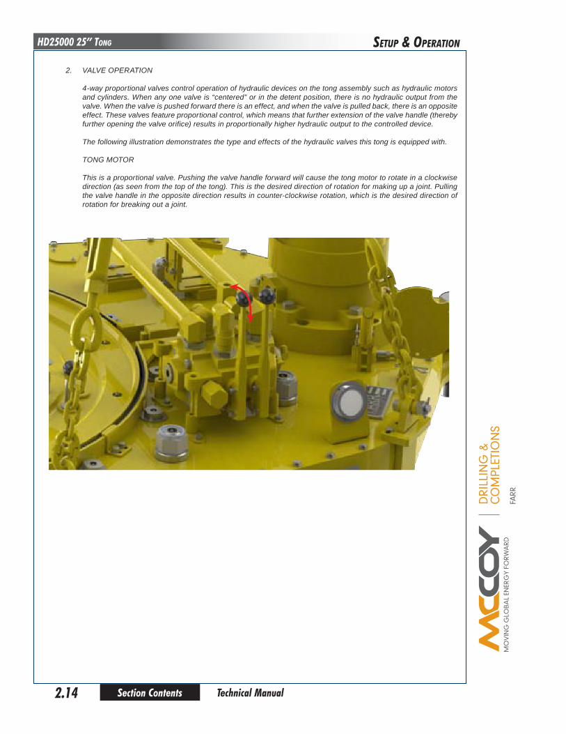
2. VALVE OPERATION 4-way proportional valves control operation of hydraulic devices on the tong assembly such as hydraulic motors and cylinders. When any one valve is “centered” or in the detent position, there is no hydraulic output from the valve. When the valve is pushed forward there is an effect, and when the valve is pulled back, there is an opposite effect. These valves feature proportional control, which means that further extension of the valve handle (thereby further opening the valve orifice) results in proportionally higher hydraulic output to the controlled device.
The following illustration demonstrates the type and effects of the hydraulic valves this tong is equipped with.
TONG MOTOR
This is a proportional valve. Pushing the valve handle forward will cause the tong motor to rotate in a clockwise direction (as seen from the top of the tong). This is the desired direction of rotation for making up a joint. Pulling the valve handle in the opposite direction results in counter-clockwise rotation, which is the desired direction of rotation for breaking out a joint.
DRI
LLIN
G &
CO
MPL
ETIO
NS
FARR
Section Contents 2.15 Technical Manual
HD25000 25” TongSETuP & oPERaTIon
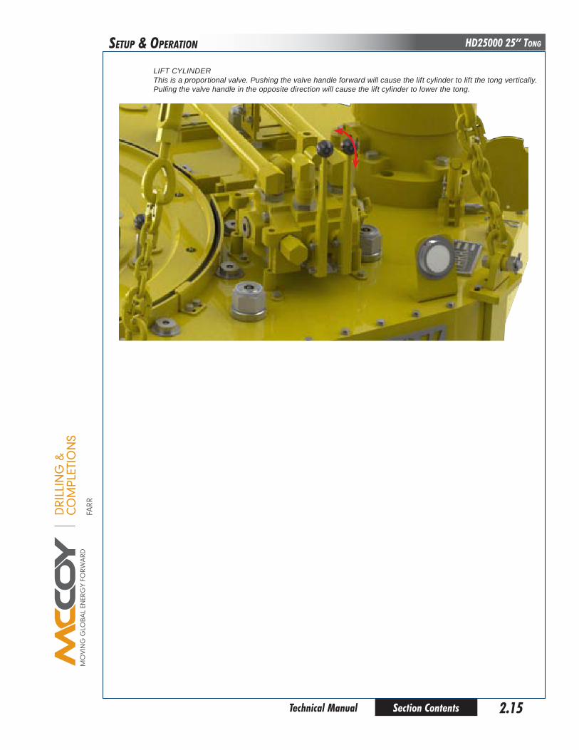
LIFT CYLINDERThis is a proportional valve. Pushing the valve handle forward will cause the lift cylinder to lift the tong vertically. Pulling the valve handle in the opposite direction will cause the lift cylinder to lower the tong.

DRI
LLIN
G &
CO
MPL
ETIO
NS
FARR
Section Contents2.16
HD25000 25” Tong
Technical Manual
SETuP & oPERaTIon
The “SNAp-bReAK” MeThod IS hAZARdouS To opeRATING peRSoNNel!
3. MAKING up A pIpe oR cASING JoINT
a. Position the tong around the pipe or casing.
b. Close and latch door completely.
c. Place the backing pin in the “make-up” position. When facing the front of the tong looking toward the rear, the “make-up” hole is to the left side of the backing pin pivot.
d. Adjust motor speed valve so that the motor will rotate at its lowest speed.
e. Push the “tong motor” handle slightly forward until the jaws “cam” with the pipe or casing, and then move the handle to its centre position so that the tong rotation stops.
f. Adjust motor speed so that the motor will rotate at its highest speed.
g. Push the tong motor handle forward to begin the rotation again, and rotate until the tong begins to “stall”. Release the handle again to its centre position.
h. Adust motor speed valve to its low speed setting to obtain highest torque. Use the tong motor valve to con-tinue to rotate the pipe or casing until the desired make-up torque is achieved.
i. Once the joint has been satisfactorally made, pull the tong motor valve handle backwards to reverse the tong rotation and disengage the jaws and rotate the rotary gear until it aligns wtih the tong door opening.
j. Unlatch the door and remove the tong from the pipe or casing.
4. bReAKING ouT A pIpe oR cASING JoINT
a. Position the tong around the pipe or casing.
b. Close and latch door completely.
c. Place the backing pin in the “break-out” position. When facing the front of the tong looking toward the rear, the “break-out” hole is to the right side of the backing pin pivot.
d. Adjust motor speed valve so that the motor will rotate at its lowest speed.
e. Pull the “tong motor” handle slightly backward until the jaws “cam” with the pipe or casing, and then move the handle to its full reverse (backward) position to begin unthreading the joint. Under general “break-out” conditions Farr Canada recommends keeping the tong motor in its slowest speed until the joint is completely uncoupled.
f. When the joint is uncoupled reverse the rotation of the tong (push tong motor handle towards the tong) to disengage the jaws. Rotate the rotary gear until it aligns wtih the tong door opening
g. Unlatch the door and remove the tong from the pipe or casing.
5. GeNeRAl coMMeNTS
a) Position rotary gear in contact with both idler gears prior to breaking out joints or collars where high torques are required.
b) When making-up integral (shouldered) joints, it is essential to make up the last turn of the threads in low gear. This reduces the tendency of an instant stop or a sudden increase in torque, which induces extremely high stresses on the gear train.
c) DO NOT employ the “snap break” method of breaking-out joints. By definition, the “snap break” method is a procedure used by some operators to break-out connections, accomplished by leaving slack in the “jaw-pipe” engagement, and then quickly pulling the throttle valve control lever allowing the tong to snap into its loaded or high torque condition. Although this method is very effective in breaking out joints, the extremely high stress placed on the gear train frequently causes gear breakage.
DRI
LLIN
G &
CO
MPL
ETIO
NS
FARR
Section Contents 2.17 Technical Manual
HD25000 25” TongSETuP & oPERaTIon
h. eXTReMe cold WeATheR opeRATIoN pRoceduReS
1) Consult the power unit engine operator’s manual for all cold weather operating procedures and precautions.
2) Select gear and bearing lubricants that are compatible with expected climatic conditions.
3) Select hydraulic fluid that is compatible with expected climatic conditions.
4) Allow hydraulic fluid to circulate for approximately 20 minutes after starting the power unit, prior to activating the bypass valve to allow fluid to circulate to tong. If the power unit is equipped with an oil temperature gauge, ensure that the fluid has reached operating temperature as specified by hydraulic fluid data sheet.
5) Allow for adequate drying of moisture (prior to lubricating) when cleaning tong parts in cold weather.

This page intentionallyleft blank
Section Contents2.18 Technical Manual
HD25000 25” Tong
DRI
LLIN
G &
CO
MPL
ETIO
NS
FARR
DRI
LLIN
G &
CO
MPL
ETIO
NS
FARR
Section Contents 3.1 Technical Manual
HD25000 25” TongMaInTEnanCE
Regular maintenance programs are necessary, and must be established to assure dependable and lengthy operation of your FARR Hydraulic Tubular Connection System. Use the following maintenance recommendations to enhance the life expectancy of the system and assure safety of operating personnel.
A. GeNeRAl MAINTeNANce SAFeTy pRAcTIceS
All maintenance must be performed by trained and authorized personnel. Wear approved eyewear, and follow all of your company’s safety guidelines.
Farr Canada recommends that disconnection of hydraulic connectors be performed with the power unit off and the hydraulic circuit depressurized.
b. cleANING
Clean tong thoroughly cleaned with a good petroleum-based cleaning agent after each job, prior to storage. Farr rec-ommends that the motor and valve assembly be periodically removed, along with the top tong plate, so that guides, rollers and gears can be properly cleaned.
c. lubRIcATIoN
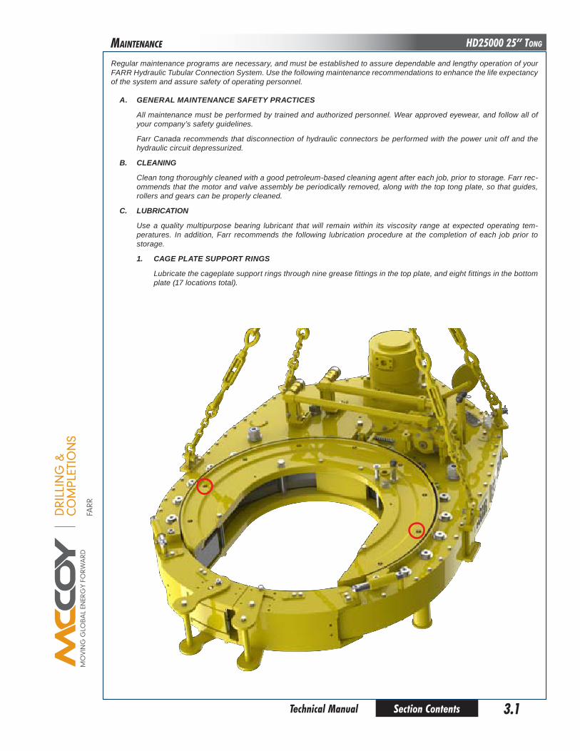
Use a quality multipurpose bearing lubricant that will remain within its viscosity range at expected operating tem-peratures. In addition, Farr recommends the following lubrication procedure at the completion of each job prior to storage.
1. cAGe plATe SuppoRT RINGS
Lubricate the cageplate support rings through nine grease fittings in the top plate, and eight fittings in the bottom plate (17 locations total).
DRI
LLIN
G &
CO
MPL
ETIO
NS
FARR
Section Contents3.2
HD25000 25” Tong
Technical Manual
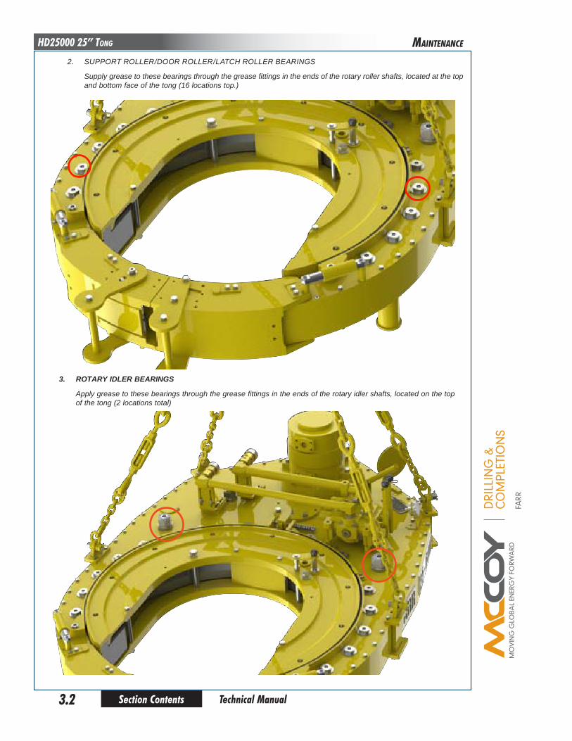
2. SUPPORT ROLLER/DOOR ROLLER/LATCH ROLLER BEARINGS
Supply grease to these bearings through the grease fittings in the ends of the rotary roller shafts, located at the top and bottom face of the tong (16 locations top.)
MaInTEnanCE
3. RoTARy IdleR beARINGS
Apply grease to these bearings through the grease fittings in the ends of the rotary idler shafts, located on the top of the tong (2 locations total)

DRI
LLIN
G &
CO
MPL
ETIO
NS
FARR
Section Contents 3.3 Technical Manual
HD25000 25” Tong
4. pINIoN IdleR beARINGS
Apply grease to these bearings through the grease fittings in the ends of the pinion idler shafts, located on the top of the tong (2 locations total)
MaInTEnanCE
5. pINIoN beARINGS
Apply grease to these bearings through the grease fittings in the pinion bearing caps located on the top and bottom of the tong (total of four locations).
DRI
LLIN
G &
CO
MPL
ETIO
NS
FARR
Section Contents3.4
HD25000 25” Tong
Technical Manual
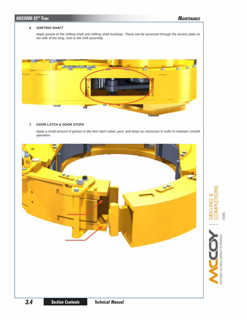
6. ShIFTING ShAFT
Apply grease to the shifting shaft and shifting shaft bushings. These can be accessed through the access plate on the side of the tong, next to the shift assembly.
MaInTEnanCE
7. dooR lATch & dooR STopS
Apply a small amount of grease to the door latch claws, post, and stops as necessary in order to maintain smooth operation.
DRI
LLIN
G &
CO
MPL
ETIO
NS
FARR
Section Contents 3.5 Technical Manual
HD25000 25” TongMaInTEnanCE
Recommended lubrication amount at the completion of each job:
1. Rotary Roller Bearings 3 shots grease (Upper and lower) 2. Rotary Idler Bearings 4 shots grease3. Pinion Idler Bearings 4 shots grease4. Pinion Bearings 2 shots grease (Upper and lower) 6. Motor Mount Bearings 1 shot grease
Farr recommends that a liberal coating of grease be applied to the cam surface of the rotary drive gear prior to jaw installa-tion.
c. AdJuSTMeNTS
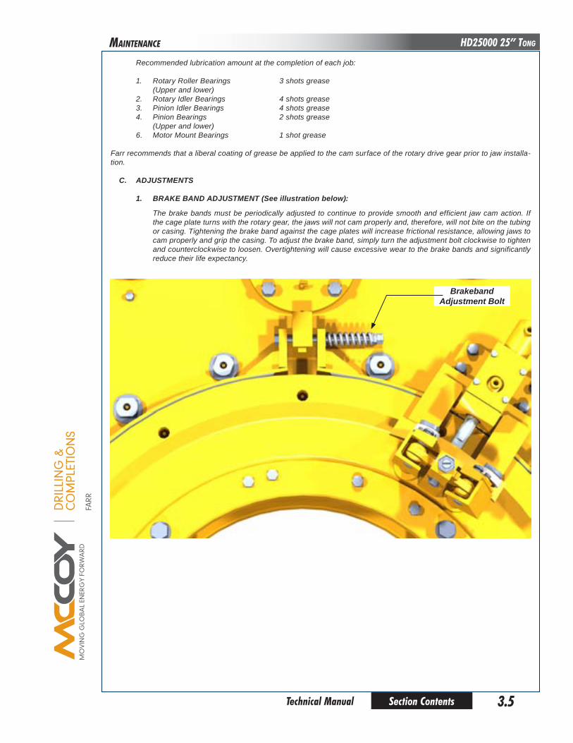
1. bRAKe bANd AdJuSTMeNT (See illustration below):
The brake bands must be periodically adjusted to continue to provide smooth and efficient jaw cam action. If the cage plate turns with the rotary gear, the jaws will not cam properly and, therefore, will not bite on the tubing or casing. Tightening the brake band against the cage plates will increase frictional resistance, allowing jaws to cam properly and grip the casing. To adjust the brake band, simply turn the adjustment bolt clockwise to tighten and counterclockwise to loosen. Overtightening will cause excessive wear to the brake bands and significantly reduce their life expectancy.
brakeband Adjustment bolt
DRI
LLIN
G &
CO
MPL
ETIO
NS
FARR
Section Contents3.6
HD25000 25” Tong
Technical Manual
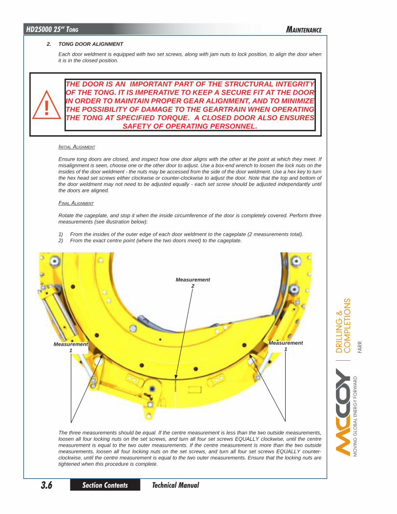
iniTial alignmenT
Ensure tong doors are closed, and inspect how one door aligns with the other at the point at which they meet. If misalignment is seen, choose one or the other door to adjust. Use a box-end wrench to loosen the lock nuts on the insides of the door weldment - the nuts may be accessed from the side of the door weldment. Use a hex key to turn the hex head set screws either clockwise or counter-clockwise to adjust the door. Note that the top and bottom of the door weldment may not need to be adjusted equally - each set screw should be adjusted independantly until the doors are aligned.
final alignmenT
Rotate the cageplate, and stop it when the inside circumference of the door is completely covered. Perform three measurements (see illustration below):
1) From the insides of the outer edge of each door weldment to the cageplate (2 measurements total).2) From the exact centre point (where the two doors meet) to the cageplate.
The three measurements should be equal. If the centre measurement is less than the two outside measurements, loosen all four locking nuts on the set screws, and turn all four set screws EQUALLY clockwise, until the centre measurement is equal to the two outer measurements. If the centre measurement is more than the two outside measurements, loosen all four locking nuts on the set screws, and turn all four set screws EQUALLY counter-clockwise, until the centre measurement is equal to the two outer measurements. Ensure that the locking nuts are tightened when this procedure is complete.
Measurement1
Measurement1
Measurement2
2. ToNG dooR AlIGNMeNT
Each door weldment is equipped with two set screws, along with jam nuts to lock position, to align the door when it is in the closed position.
The dooR IS AN IMpoRTANT pART oF The STRucTuRAl INTeGRITy oF The ToNG. IT IS IMpeRATIve To Keep A SecuRe FIT AT The dooR IN oRdeR To MAINTAIN pRopeR GeAR AlIGNMeNT, ANd To MINIMIZe The poSSIbIlITy oF dAMAGe To The GeARTRAIN WheN opeRATING The ToNG AT SpecIFIed ToRque. A cloSed dooR AlSo eNSuReS
SAFeTy oF opeRATING peRSoNNel.
!
MaInTEnanCE

DRI
LLIN
G &
CO
MPL
ETIO
NS
FARR
Section Contents 3.7 Technical Manual
HD25000 25” Tong
d. RecoMMeNded peRIodIc checKS
1. DOOR STOP SPRING
The spring inside the actuator cylinder must be of sufficient strength to enable the door latch mechanism to snap closed properly. Door stop spring fatigue will result in sluggish latch operation. Replace the latch spring inside the cylinder when this occurs.
2. BACKING PIN
Perform a visual inspection of the backing pin after each job. Replace the pin if stress cracks or excessive wear is found, or if either pin is bent.
3. TORQUE GAUGE ASSEMBLY
Periodic calibration of the torque gauge is recommended to assure accurate torque readings. When having the torque gauge serviced and calibrated, it is critical to note the arm length of the tong, as indicated in the “Specifications” section. Farr recommends that the torque gauge assembly be calibrated yearly.
e. oveRhAul pRoceduReS
Once the tong has been removed from frame assembly, it may be overhauled using the disassembly instructions speci-fied in the following procedure. Access to the gear train is possible by removal of the top plate of the tong.
ALL MAINTENANCE AND OVERHAUL SHOULD BE PERFORMED FROM THE TOP. THEREFORE, THE BOTTOM PLATE OF THE TONG SHOULD NEVER BE
REMOVED FROM THE GEAR CASE HOUSING.
ANy ReplAceMeNT FASTeNeR (bolTS, NuTS, cAp ScReWS, MAchINe ScReWS, eTc.) uSed duRING MAINTeNANce oR oveRhAul MuST be
GRAde 8 oR equIvAleNT!WheN Re-ASSeMblING loAd-beARING coMpoNeNTS (chAIN SlINGS, RIGId SlINGS, bAcKup leGS) NoTe ThAT The ASSocIATed FASTeNeRS MuST be TIGhTeNed To The coRRecT ToRque SpecIFIed FoR ThAT SIZe oF FASTeNeR. checK All chAINS FoR dAMAGe beFoRe plAcING uNdeR loAd. eNSuRe chAINS ARe NoT KINKed beFoRe plAcING
uNdeR loAd.!
MaInTEnanCE

DRI
LLIN
G &
CO
MPL
ETIO
NS
FARR
Section Contents3.8
HD25000 25” Tong
Technical Manual
TIGhTeNING ToRque GuIdeSAe GRAde 8 - FINe ThReAd
SIZe clAMp loAd plAIN plATed1/4 - 28 (.250) 3,263 14 ft. lbs. 10 ft. lbs.
5/16- 24 (.3125) 5,113 27 ft. lbs. 20 ft. lbs.
3/8 - 24 (.375) 7,875 49 ft. lbs. 37 ft. lbs.
7/16 - 20 (.4375) 10,650 78 ft. lbs. 58 ft. lbs.
1/2 - 20 (.500) 14,400 120 ft. lbs. 90 ft. lbs.
9/16 - 18 (.5625) 18,300 172 ft. lbs. 129 ft. lbs.
5/8” - 18 (.625) 23,025 240 ft. lbs. 180 ft. lbs.
3/4 - 16 (.750) 33,600 420 ft. lbs. 315 ft. lbs.
7/8” - 14 (.875) 45,825 668 ft. lbs. 501 ft. lbs.
1 - 12 (1.000) 59,700 995 ft. lbs. 746 ft. lbs.
1 - 14 (1.000) 61,125 1019 ft. lbs. 764 ft. lbs.
1 1/8 - 12 (1.125) 77,025 1444 ft. lbs. 1083 ft. lbs.
1 1/4 - 12 (1.125) 96,600 2012 ft. lbs. 1509 ft. lbs.
1 3/8 - 12 (1.375) 118,350 2712 ft. lbs. 2034 ft. lbs.
1 1/2 - 12 (1.500) 142,275 3557 ft. lbs. 2668 ft. lbs.
SAe GRAde 8 - coARSe ThReAdSIZe clAMp loAd plAIN plATed
1/4 - 20 (.250) 2,850 12 ft. lbs. 9 ft. lbs.
5/16- 18 (.3125) 4,725 25 ft. lbs. 18 ft. lbs.
3/8 - 16 (.375) 6,975 44 ft. lbs. 33 ft. lbs.
7/16 - 14 (.4375) 9,600 70 ft. lbs. 52 ft. lbs.
1/2 - 13 (.500) 12,750 106 ft. lbs. 80 ft. lbs.
9/16 - 12 (.5625) 16,350 153 ft. lbs. 115 ft. lbs.
5/8” - 11 (.625) 20,325 212 ft. lbs. 159 ft. lbs.
3/4 - 10 (.750) 30,075 376 ft. lbs. 282 ft. lbs.
7/8” - 9 (.875) 41,550 606 ft. lbs. 454 ft. lbs.
1 - 8 (1.000) 54,525 909 ft. lbs. 682 ft. lbs.
1 1/8 - 7 (1.125) 68,700 1288 ft. lbs. 966 ft. lbs.
1 1/4 - 7 (1.125) 87,225 1817 ft. lbs. 1363 ft. lbs.
1 3/8 - 6 (1.375) 103,950 2382 ft. lbs. 1787 ft. lbs.
1 1/2 - 6 (1.500) 126,450 3161 ft. lbs. 2371 ft. lbs.
ANy ReplAceMeNT FASTeNeR (bolTS, NuTS, cAp ScReWS, MAchINe ScReWS, eTc.) uSed duRING MAINTeNANce oR oveRhAul MuST be
GRAde 8 oR equIvAleNT.!WheN Re-ASSeMblING loAd-beARING coMpoNeNTS (chAIN SlINGS, RIGId SlINGS, bAcKup leGS) NoTe ThAT The ASSocIATed FASTeNeRS MuST be TIGhTeNed To The coRRecT ToRque SpecIFIed FoR ThAT
SIZe oF FASTeNeR.!
MaInTEnanCE

DRI
LLIN
G &
CO
MPL
ETIO
NS
FARR
Section Contents 3.9 Technical Manual
HD25000 25” Tong
apply a tHin layer of greaSe to tHe Surface of eacH moving part during aSSembly to aid in tHe aSSembly proceSS.1. Position the tong body gear case on a suitable stationary support such that the bottom body plate is accessible.
2. Insert support roller inner spacer (PN 1037-C-134) into each of the sixteen support (“dumbell”) rollers (PN 1482-135). Press two support roller bearings (PN 02-0094) into each end of each support roller (16 assemblies total). Once the assembly of the support rollers is complete, slide a bearing spacer (PN 101-3871) over each of the four-teen “shouldered“ support roller shafts, and then temporarily slide the support roller shafts into each assembly for assistance in correctly positioning each support roller. Once the fourteen shafts have been inserted through the support roller assemblies, slide a second bearing spacer over the end of each shaft. Slide the two “unshouldered” shafts (brakeband anchor shafts) through the remaining two support roller assemblies, and slide a bearing spacer over each end. NOTE: Do not include the two door pivot rollers or the two door rollers in this step - only perform this action with the sixteen body rollers.
3. Place rotary gear on bottom plate, oriented so that the opening in the gear faces the first five support roller posi-tions on the side of the tong. Install five support roller assemblies, including shafts but not including fasteners - use caution that the bearing spacer on the bottom side of the assembly remains in place. Continue to rotate rotary gear around the tong, installing the support roller assemblies as the gear is rotated. Finish with the rotary gear aligned with the opening in the bottom plate (see following illustration).
4. Press pinion bearing (PN 02-0106) into bottom pinion bearing cap (PN 1037-C-33), and install bearing cap into bottom plate of tong using four 5/8” SS lockwashers and four 5/8” NC x 1-3/4” SS wire-drilled hex cap screws.
5. Press lower clutch bearing (PN 02-0105) into bottom clutch bearing cap (PN 1037-C-17), and install bearing cap into bottom plate of tong using four 5/8” SS lockwashers and four 5/8” NC x 1-3/4” SS wire-drilled hex cap screws.
6. Install a retaining ring (PN 02-0009) into each of the two rotary idler gears (PN 1037-D59). Press one each of the idler bearings (PN 02-0011) into each of the rotary idler gears, followed by a second retainer ring in each. Slide each rotary idler gear and bearing assembly over an idler shaft (PN 1050-D5-117) and centre as well as you are able.
7. Slide a bearing seal (PN 02-0010) over each end of the rotary idler shafts, ensuring that the “lip” on the seals are towards the centre bearing, followed by an idler spacer (PN 1050-D5-121) over each end of the shafts.
8. Install each rotary idler in their respective locations in the bottom plate and mesh with the rotary gear. NOTE: when the rotary idler assemblies are placed vertically, the bearing seal and idler spacer on the bottom side will have to be held in place by hand as the assembly is lowered through the bottom plate. Once the assembly is through the bottom plate, place an idler pad (PN 1037-A-8) over the bottom end of each shaft, and secure the pads with a 1-1/2” UNF wire-drilled SS hex nut (PN 101-3923).
MaInTEnanCE

DRI
LLIN
G &
CO
MPL
ETIO
NS
FARR
Section Contents3.10
HD25000 25” Tong
Technical Manual
MechANIcAl ASSeMbly SequeNce (continued):
9. Slide low pinion gear (PN 1037-D-32) over bottom end of pinion gear shaft (PN 1037-D-15), and place end of pinion gear shaft into previously installed pinion bearing. Ensure the gear keys (PN 1037-D-15A), are placed into the pinion gear shaft before installing gear (two keys per gear).
10. Install a retaining ring (PN 02-0009) into each of the two pinion idler gears (PN 1037-D-1). Press one each of the idler bearings (PN 02-0011) into each of the pinion idler gears, followed by a second retainer ring in each. Slide each rotary idler gear and bearing assembly over an idler shaft (PN 1050-D5-117) and centre as well as you are able.
11. Slide a bearing seal (PN 02-0010) over each end of the rotary idler shafts, ensuring that the “lip” on the seals are towards the centre bearing, followed by an idler spacer (PN 1050-D5-121) over each end of the shafts.
12. Install each rotary idler in their respective locations in the bottom plate and mesh with the pinion gear shaft. NOTE: when the rotary idler assemblies are placed vertically, the bearing seal and idler spacer on the bottom side will have to be held in place by hand as the assembly is lowered through the bottom plate. Once the assem-bly is through the bottom plate, place an idler pad (PN 1037-A-8) over the bottom end of each shaft, and secure the pads with a 1-1/2” UNF wire-drilled SS hex nut (PN 101-3923).
13. Slide clutch bearing (PN 02-0104) over the bottom end of the splined clutch shaft (PN 1037-D-38), and install two upper clutch bearings (PN 02-0103) over the top side of the clutch shaft. Press bearings tight to the center gear on the splined clutch shaft.
14. Slide the low clutch gear (PN 1037-D-40) over the lower bearing so that the larger diameter of the low clutch gear is tight to the center gear on the clutch shaft, and place end of clutch shaft into the clutch bearing installed in Step 5. Mesh the low clutch gear with the low pinion gear as it is installed.
15. Place the shifting collar (PN 1037-D-34) over the middle section of the clutch shaft.
16. Slide the high clutch gear (PN 1037-D-41) over the two top clutch bearings.
17. If not already done, insert the two remaining gear keys in the pinion gear shaft. Install the high pinion gear (PN 1037-D-12) over the top of the pinion gear shaft, meshing with the high clutch gear as it is installed.
18. Fasten the lower shifter bushing (PN 1037-C-21B) to the bottom plate with four 3/8” NC x 1-1/4” SS wire-drilled hex bolts and 3/8” SS lockwashers.
19. Place the shifting fork weldment (PN 1037-D-27) up against the shifting shifting collar, roughly in its final posi-tion.
20. Carefully remove all the support roller shafts, ensuring the support roller assemblies do not shift position as you are doing so - also ensure the top support roller bearing spacers remain in place when the shafts are removed.
21. Insert three 3/8” x 1-1/2” hardened ground production dowel pins into the side body - one at exact rear centre, and one on either side of the front opening. Position the top plate in its proper location - use caution not to damage threads when aligning the top plate with the idler shafts. Ensure the plate is aligned exactly horizontal to prevent binding on the dowel pins. Tap plate securely into place with a rubber mallet.
22. Secure the top plate with forty-four 3/8” NC x 1-1/2” SS wire-drilled hex bolts and SS lockwashers and six 3/8” NC x 1” SS wire-drilled hex socket cap screws. Note that fasteners are not to be installed at the chain sling hanger locations.
23. Slide a 1-1/8” narrow SS washer over the end of each “shouldered” support roller shafts, and re-insert the four-teen shafts through their proper locations - Note that the two locations on each side of the tong opening should remain open (See Geartrain Layout - Pp. 6.2 - 6.3 for an illustration of locations). Once the shafts have been installed slide a 1” narrow SS flatwasher over the bottom of each shaft, and secure each shaft with a 1” UNF wire-drilled SS jam nut (PN 101-3922).
24. Insert the two remaining “unshouldered” support roller shafts through their proper locations in the top plate. Temporarily leave these two shafts unsecured.
25. Slide the remaining idler pads over the top of the four idler shafts, and secure each with the remaining 1-1/2” UNF wire-drilled SS jam nuts.
26. Press the remaining bearing in the pinion assembly into the top pinion bearing cap (PN 1037-C-10), and install the bearing cap in the top plate of the tong using four 5/8” SS lockwashers and four 5/8” NC x 1-1/2” SS wire-drilled hex cap screws. Note that the flat on the bearing cap faces toward the rear of the tong.
27. Install shifting assembly in the appropriate location at the rear of the tong.
MaInTEnanCE

DRI
LLIN
G &
CO
MPL
ETIO
NS
FARR
Section Contents 3.11 Technical Manual
HD25000 25” Tong
MechANIcAl ASSeMbly SequeNce (continued):
28. Mate shifting shaft with shifter fork - the alignment process can be done through the access panel on the left rear side of the tong. Secure the shifting fork weldment to the bottom of the shifting shaft using a 7/8” UNF heavy hex nut - once the shifting fork has been secured, place the bottom of the shifting shaft into the lower shifting bushing. Secure in place with fasteners outlined in assembly drawings.
29. Place the motor shaft spacer over the top of the splined clutch shaft.
30. Install the motor mount (PN 1037-D-7) ensuring that the flat on the motor mount is oriented toward the pinion bearing cap and the “small flat” on the motor mount is oriented to accomodate the shifter cylinder. Secure with five 3/4” NC x 1-1/4” SS hex socket head cap screws and 3/4” lockwashers.
31. Install hydraulic motor. Use caution to make sure the splines on the motor shaft are properly aligned with the grooves in the clutch shaft, and secure with five 5/8” NC x 2-1/2” SS wire-drilled hex bolts and 5/8” lockwash-ers.
32. Install a support ring (PN 1482-23) into the top of the rotary gear using fifteen 1/2” NC x 2-1/4” hex socket head cap screws.
33. Install the second support ring onto the inside of the bottom cageplate (PN 101-3574) using fifteen 1/2” NC x 2-1/4” hex socket head cap screws.
34. Position the top cageplate weldment and bottom cageplate assembly above and below the tong opening, and secure to each other using five 1” NC x 8-1/2” SS wire-drilled hex bolts. Ensure the rear cageplate spacer (PN 1482-21-1) is in place before inserting the two rear bolts, and use the tubular cageplate spacers between the remaining three bolts.
35. Install the lower latch weldment (PN 101-1333) and latch spring (PN 1482-11A-12) into the RH door weldment as shown in the following illustration. Note that for reasons of clarity, the door stiffener plate is not shown. Once the latch and spring are in place, install a latch cover plate and secure with six 1/4” x 1” hex bolts and 1/4” lockwash-ers. Repeat for the top latch weldment and latch spring.
MaInTEnanCE
DRI
LLIN
G &
CO
MPL
ETIO
NS
FARR
Section Contents3.12
HD25000 25” Tong
Technical Manual
MechANIcAl ASSeMbly SequeNce (continued):
36. Place the auto door latch handle weldment against the bottom plate of the RH door weldment so that the bot-tom latch pin weldment, installed in the previous step, is inside the “L-shaped” latch slide cutout and the handle extends up the front of the door weldment.
37. Place the latch handle plate against the top plate so that the top latch pin weldment, installed in step 35, is inside the “L-shaped” latch slide cutout and the front of the plate connects to the latch handle. Secure the latch plate to the latch handle with a 1/2” NC x 1-1/4” SS hex bolt and a 1/2” SS lockwasher.
38. Press a latch bushing (PN 02-0520) in each of the top and bottom latch plates. Slide a latch A-link spacer (PN 1482-12-08) between each latch handle plate and the top and bottom door RH weldment plates, and secure the latch plates to the RH weldment using 5/8” x 3/4” hex socket head SS shoulder bolts and 5/8” narrow SS lock-washers.
39. Press door pivot shoulder bushings (PN 101-4670) into the top and bottom tong body plates at the door pivot locations. The shoulders on the bushings in the top plate face up, and the shoulders on the bushings in the bottom plate face down (see Door Assembly drawing).
40. Install the door pivot roller components that fit between the two body plates, i.e. everything except the roller shafts.
41. Install the RH door assembly. Use caution when inserting through the support roller components. When the door pivot roller is fully inserted, secure it on the bottom door plate with a pin lock plate (PN 1482-11-05), two 3/8” NC x 1” SS hex bolts and two 3/8” SS lockwashers.
42. Install the LH door weldment and insert the LH door pivot roller shaft - use caution when inserting through the support roller components. Secure the shaft on the top plate of the LH door weldment with a pin lock plate, two 3/8” NC x 1” SS hex bolts and two 3/8” SS lockwashers.
43. Press a door roller bearing into one end of each door dumbell roller. Insert the door roller inner sleeves into the rollers, and press the remaining two bearings into the rollers.
44. Place a door roller spacer (PN 1482-11-06) above and below the door roller assembled in the previous step, and insert one of each assembly into the interior of each door assembly. Insert a door roller shaft (PN 1482-11-04) from the top, through each door roller, and secure each shaft with a pin lock plate, two 3/8” NC x 1” SS hex bolts and two 3/8” SS lockwashers. (See illustration next page)
MaInTEnanCE

DRI
LLIN
G &
CO
MPL
ETIO
NS
FARR
Section Contents 3.13 Technical Manual
HD25000 25” Tong
MechANIcAl ASSeMbly SequeNce (continued):
45. Install door cylinders onto the mounting posts on both the RH and LH door assembly and both sides of the top tong plate. Secure in place with fasteners shown on Door Assembly drawing.
46. Place the anchor end of a lined brakeband weldment over one of the two remaining support roller shafts, and secure the brakeband weldment with a 1” external retaining ring, and a brakeband retainer clip c/w two 3/8” NC x 1” SS wire-drilled hex bolts and 3/8” SS lockwashers). Repeat the procedure with the remaining three lined brakeband weldments.
47. Thread a 3/8” NC x 1-1/4” SS hex socket set screw into each brakeband guide (PN 101-3586) - do not thread far enough that it protrudes into the inside.
48. Place a brakeband guide over the top brakeband lug (welded to the top plate directly behind the top cageplate), and insert a 1/2” NC x 8” SS adjustment bolt through the tabs on both brakeband weldments and the brakeband tab and guide. Slide a brakeband spring over the end of the bolt, followed by a 1/2” SS narrow flatwasher, two 1/2” NC SS hex jam nuts, and a 1/2” NC palnut in that order. Repeat this step for the bottom brakebands.
49. Thread the set screws into the brakeband guides just until the set screw contacts the brakeband lug welded to the top plate. Once tong operation commences, the position of the guide may be adjusted to compensate for iregularities in brakeband operation such as noise or uneven action of the brakebands.
50. Install backing pin assembly onto the top cageplate. Reference Rotary Assembly drawing for fasteners used.
MaInTEnanCE

This page intentionallyleft blank
Section Contents3.14 Technical Manual
HD25000 25” Tong
DRI
LLIN
G &
CO
MPL
ETIO
NS
FARR

DRI
LLIN
G &
CO
MPL
ETIO
NS
FARR
Section Contents 4.1 Technical Manual
HD25000 25” TongTRoubLESHooTIng
Adequate maintenance and proper fluid selection should keep hydraulic problems to a minimum. If troubleshooting is necessary, ensure that the technician is well-trained in hydraulic systems, and familiar with the equipment design, assembly and operation. Knowledge of hydraulic circuits and components is essential in isolating trouble areas and pinpointing particular faults.
The following troubleshooting guidelines are intended to be general in nature. Any faults not solved through the use of this guide should be referred to our engineering department for their evaluation and recommendations.
A. poWeR uNIT puMp MAKeS eXceSSIve NoISe
1. POSSIBLE PROBLEM: Plugged or restricted intake line. SOLUTION: Clean intake line.
2. POSSIBLE PROBLEM: Plugged reservoir air vent. SOLUTION: Clean or replace.
3. POSSIBLE PROBLEM: Fluid viscosity too high due to low ambient temperature. SOLUTION: Replace fluid with a type that maintains the proper viscosity range in the operating environment.
4. POSSIBLE PROBLEM: Air leaking into system. SOLUTION: Ensure oil pickup is well below oil surface level in reservoir. Check pump packing and line connections on intake side by pouring oil over the suspected leak. If the noise stops, the leak has been located. Tighten joints or change packing or gaskets where necessary.
5. POSSIBLE PROBLEM: Loose or worn parts. SOLUTION: Replace parts. NOTE: Improper selection of hydraulic fluid may result in premature wear.
6. POSSIBLE PROBLEM: Pump misalignment with motor. SOLUTION: Check alignment.
7. POSSIBLE PROBLEM: Pump running in excess of rated speed. SOLUTION: Check manufacturer’s recommended speed. Check pulleys, gears, power takeoff, or drive motor.

DRI
LLIN
G &
CO
MPL
ETIO
NS
FARR
Section Contents4.2
HD25000 25” Tong
Technical Manual
TRoubLESHooTIng
b. hydRAulIc SySTeM oveRheATING
1. POSSIBLE PROBLEM: Excess discharge pressure (relief valve set too high). SOLUTION: Reset relief valve in accordance with maximum pressure required. Check manufacturer’s recommenda- tions.
2. POSSIBLE PROBLEM: Fluid viscosity too high or too low due to extreme ambient temperatures. SOLUTION: Replace fluid. (Check pump and motor manufacturer’s recommendations.)
3. POSSIBLE PROBLEM: Excessive internal leakage. SOLUTION: Repair or replace any worn parts (loose packing, etc.)
4. POSSIBLE PROBLEM: Excessive friction. SOLUTION: Check pump for part interference. Pump may be assembled too tightly.
5. POSSIBLE PROBLEM: Leaks in pump check valve or relief valve. SOLUTION: Repair or replace.
6. POSSIBLE PROBLEM: Fluid level in reservoir too low for proper cooling. SOLUTION: Maintain proper oil level.
7. POSSIBLE PROBLEM: Pump discharge being restricted. SOLUTION: Check operation of throttle valve. Check relief valve. Do not allow larger pump volumes to remain at high pressure for long periods of time. Check all self-sealing hose connections for proper engagement.
8. POSSIBLE PROBLEM: Hydraulic system valves restricted. SOLUTION: Clean valves and piping.
9. POSSIBLE PROBLEM: Heat exchanger not cooling hydraulic fluid. SOLUTION: •Hydrauliccircuitthroughheatexchangerisobstructed. •Coolingcoilsinheatexchangermaybecoatedwithalayerofdust. •Airflowthroughheatexchangermaybeobstructed. •Coolingfanmaybemalfunctioning

DRI
LLIN
G &
CO
MPL
ETIO
NS
FARR
Section Contents 4.3 Technical Manual
HD25000 25” TongTRoubLESHooTIng
c. eXceSSIve WeAR oF MovING pARTS
1. POSSIBLE PROBLEM: Abrasive contaminants entrained in the fluid. SOLUTION: Change fluid more frequently. Replace filter element. Be sure filter is proper size.
2. POSSIBLE PROBLEM: Misalignment of moving parts. SOLUTION: Inspect and realign.
3. POSSIBLE PROBLEM: Operating pressure rises above manufacturer’s recommendations. SOLUTION: Check relief valve and reset.
4. POSSIBLE PROBLEM: Viscosity of fluid too low at working temperature. SOLUTION: Ensure fluid is compatible with operating temperature.
5. POSSIBLE PROBLEM: Air in system. SOLUTION: Bleed air and check for leaks in system.
6. POSSIBLE PROBLEM: Excessive wear of bearings. SOLUTION: Inspect alignment of moving parts, vibration or excessive side thrusts on shafts.
DRI
LLIN
G &
CO
MPL
ETIO
NS
FARR
Section Contents4.4
HD25000 25” Tong
Technical Manual
TRoubLESHooTIng
d. ToNG RuNNING Too SloWly
1. POSSIBLE PROBLEM: Pump intake line plugged. SOLUTION: Clean intake line.
2. POSSIBLE PROBLEM: Reservoir oil level too low. SOLUTION: Add oil.
3. POSSIBLE PROBLEM: Air leak in pump intake line. SOLUTION: Repair leak.
4. POSSIBLE PROBLEM: Pump speed too slow. SOLUTION: Check manufacturer’s speed recommendations.
5. POSSIBLE PROBLEM: Excessively worn or damaged pump or tong. SOLUTION: Replace worn parts by following manufacturer’s recommendations.
6. POSSIBLE PROBLEM: Fluid viscosity too high. SOLUTION: Some pumps will not prime if the fluid is too heavy.
7. POSSIBLE PROBLEM: Restriction in line between power unit and tong. SOLUTION: Check self-sealing couplings to insure they are properly engaged.
8. POSSIBLE PROBLEM: By-pass valve not functioning. SOLUTION: Check and repair.
BYPASS ALL TONG CIRCUITRY TO TEST PRESSURE AND VOLUME. IF FLOW AND PRESSURE ARE TESTED OFTEN,
FARR RECOMMENDS CONSTRUCTION OF A TEST RIG THAT CAN EASILY BE CONNECTED TO THE PUMP SUCTION AND
DISCHARGE PORTS*
DRI
LLIN
G &
CO
MPL
ETIO
NS
FARR
Section Contents 4.5 Technical Manual
HD25000 25” TongTRoubLESHooTIng
e. ToNG WIll NoT develop SuFFIcIeNT ToRque
1. Malfunctioning relief valve on unit or tong.
a. POSSIBLE PROBLEM: Relief pressure set too low. SOLUTION: Increase setting. To check, block the oil line beyond the relief valve and determine pressure with a gauge.
b. POSSIBLE PROBLEM: Valve is stuck. SOLUTION: Check for contamination of oil that may inhibit the way the valve actuates. Remove valve and clean, ensuring that the valve spring operates smoothly.
c. POSSIBLE PROBLEM: Valve is leaking. SOLUTION: Check valve seat for scouring. Check oil seals. Check for particles stuck under the valve system.
2. POSSIBLE PROBLEM: Worn or damaged pump parts. SOLUTION: Inspect and clean, replace all worn or broken parts.
3. POSSIBLE PROBLEM: Pump speed too slow. SOLUTION: Check motor speed.
4. POSSIBLE PROBLEM: Fluid viscosity too high. SOLUTION: Pump may not prime if fluid is too heavy. Replace with proper viscosity fluid.
5. POSSIBLE PROBLEM: Viscosity of fluid too low. SOLUTION: System may overheat. Replace with proper viscosity fluid.
6. POSSIBLE PROBLEM: Fluid by-passed to reservoir. SOLUTION: Check relief valve for proper operation. Check directional valve. Neutral position should return fluid directly to the reservoir.
7. POSSIBLE PROBLEM: Worn or damaged tong motor causing slippage. SOLUTION: Replace or repair worn or damaged parts.
8. POSSIBLE PROBLEM: Damaged bearings or gears causing excessive drag. SOLUTION: Repair or replace worn parts.
9. POSSIBLE PROBLEM: Poor hydraulic pressure at the tong or excessive back pressure in the return line. SOLUTION: Restriction in line between power unit and tong. Inspect integrity of self-sealing couplings.
10. POSSIBLE PROBLEM: Defective torque gauge or load cell. SOLUTION: Replace defective components. Ensure dampening screw has been adjusted. Ensure gauge has been calibrated to proper torque arm length.

DRI
LLIN
G &
CO
MPL
ETIO
NS
FARR
Section Contents4.6
HD25000 25” Tong
Technical Manual
TRoubLESHooTIng
F. FAIluRe oF JAWS To GRIp pIpe
1. POSSIBLE PROBLEM: Dies have become too dull. SOLUTION: Replace dies.
2. POSSIBLE PROBLEM: Brake band insufficiently adjusted, not allowing jaws to cam properly. SOLUTION: Adjust brake bands to give proper resistance to cage plates.
3. POSSIBLE PROBLEM: Jaw roller broken or worn. SOLUTION: Replace roller.
4. POSSIBLE PROBLEM: Incorrect size jaws installed. SOLUTION: Double-check that proper size jaws are installed..
DRI
LLIN
G &
CO
MPL
ETIO
NS
FARR
Section Contents 4.7 Technical Manual
HD25000 25” TongTRoubLESHooTIng
G. GeNeRAl coMMeNTS
The following factors contribute highly to inefficient hydraulic operation:
1. Failure to change fluid frequently enough, or inadequate fluid filtration.
2. Unsuitable hydraulic fluid.
3. Defective packing or seals in components of the hydraulic system.
4. Poor or incomplete understanding of hydraulic system components and/or operation of the equipment.
5. Ensure hydraulic fluid is at operating temperature. Failure to do so may result in incorrect operation of sequenced valves and general inconsistent system operation.
DRI
LLIN
G &
CO
MPL
ETIO
NS
FARR
Section Contents4.8
HD25000 25” Tong
Technical Manual
TRoubLESHooTIng
h. GeNeRAl coMMeNTS
The following factors contribute highly to inefficient hydraulic operation:
1. Failure to change fluid frequently enough, or inadequate fluid filtration.
2. Unsuitable hydraulic fluid.
3. Defective packing or seals in components of the hydraulic system.
4. Poor or incomplete understanding of hydraulic system components and/or operation of the equipment.
DRI
LLIN
G &
CO
MPL
ETIO
NS
FARR
Section Contents 5.1 Technical Manual
HD25000 25” TongDECoMISSIonIng, SToRagE, & RECoMMISIonIng
Perform the following decommisioning procedures when removing tubular connection equipment from service, with the intent of short to long-term storage. These procedures are essential for ensuring proper protection of the equipment from environmental attack, and to aid in the quick turnaround when returning the equipment to service.
Store all o-rings, seals, packings, gaskets, etc. in strong moisture proof, airtight containers. Ensure that these items are not crushed, nicked, or otherwise damaged.
Do not perform any further actions or maintenance while the tong is connected to any hydraulic power supply. Farr Canada recommends that all hydraulic lines are fully disconnected, and residual hydraulic pressure is bled off. Ensure adequate containment is in place to prevent environmental contamination from residual hydraulic fluid.
depreSSurization procedure in preparation for Storage:1) Rotate the tong so that the opening in the rotary gear faces the geartrain (towards the rear of the tong). Ensure tong
and backup doors (if equipped) are closed. Fully extend the lift cylinder (if equipped). If mounted in a frame, retract the float cylinders (if equipped).
2) De-energize the power unit.
3) Repeatedly actuate the tong motor control valve lever IN BOTH DIRECTIONS to dissipate any residual pressure in the valve and motor.
4) Remove the hydraulic SUPPLY line from the equipment.
5) Repeatedly actuate the remaining control valve levers IN BOTH DIRECTIONS to dissipate any residual pressure in the remainder of the hydraulic control system.
7) Disconnect the hydraulic RETURN line from the equipment.
8) Disconnect remaining hoses such as case drains, or lines connected to the turns counter.
Hydraulic pressures as HigH as operating pressure may remain trapped in small areas of tHe equipment. ensure all maintenance is carried out by a qualified service tecHnician, and tHat adequate personal protec-
tive equipment is used to guard against pressure injuries!
1. Perform an initial wash of the tool in order to remove the majority of dirt and grease build-up. Ensure adequate containment is in place to prevent environmental contamination from residual hydraulic fluid and dirty grease.
2. Remove the access panel on the side of the tong directly adjacent to the shifter mechanism.
3. Clean the interior of the tong thoroughly, using either water (do not use a pressure washer), or an appropriate solvent-based grease-cutting cleaner such as Varsol. Ensure adequate containment is in place to prevent envi-ronmental contamination from residual hydraulic fluid, dirty grease, and cleaning agents. Make a note if any metal shavings or metal pieces are flushed out of the geartrain cavity - if shavings or metal pieces are seen the tong must be overhauled before it is returned to service.
4. Clean the exterior of the tool thoroughly, using either water (do not use a pressure washer), or an appropriate solvent-based grease-cutting cleaner such as Varsol. Ensure adequate containment is in place to prevent envi-ronmental contamination from residual hydraulic fluid, dirty grease, and cleaning agents.
5. Inspect all fasteners and fastener safety wires. Replace any missing fasteners - use Grade 8 bolts only. Re-torque all external fasteners to SAE specifications.
6. Inspect lifting and support devices, including chain slings, rigid slings, legs, leg mounts, and lifting lugs. Refer to Section 2.A for proper inspection and quarantine, and repair guidelines.
7. Inspect backing pin(s). If cracked, broken, or bent it (they) must be replaced.
8. Repair or replace any damaged or missing external body parts, such as torque gauge mounts, hydraulic supports, safety door protectors, etc.
9. Inspect all paint - locations in which the paint has been damaged must be repaired prior to storage. Prepare areas to be painted to ensure they are free of grease, dirt, or solvent. Touch up using a solvent-based acrylic paint - “Farr Canada Blue” is paint number RAL.5005. Allow sufficient time for paint to dry before proceeding.
10. Perform a liberal lubrication of the equipment - refer to Maintenance section of manual to determine lubrication points. Generously fill the geartrain housing with grease through the access panel, and also through the opening in the rotary gear.
11. Connect the equipment to a hydraulic power unit. Ensure all lines are fully made up to prevent equipment damage from excessive back pressure. Do not neglect to connect the motor drain.
12. Energize power unit.
DRI
LLIN
G &
CO
MPL
ETIO
NS
FARR
Section Contents5.2
HD25000 25” Tong
Technical Manual
depreSSurization procedure for Storage:1) Rotate the tong to the “open throat” position.
2) Exercise each hydraulic cylinder several times - open the tong and backup doors (if equipped), retract and extend the remote backing pin ramp (if equipped), retract and extend the float cylinders. Leave all cylinders except for the door cylinders in their fully retracted position. The general idea is to have as little of the chrome cylinder rods exposed as possible.
3) De-energize the power unit.
4) Repeatedly actuate the tong motor control valve lever IN BOTH DIRECTIONS to dissipate any residual pressure in the valve and motor.
5) Remove the hydraulic SUPPLY line from the equipment.
6) Repeatedly actuate the remaining control valve levers IN BOTH DIRECTIONS to dissipate any residual pressure in the remainder of the hydraulic control system.
7) Connect a low-pressure air supply line (10 PSI or less) to the hydraulic supply line, and force a small amount of the remaining hydraulic fluid from the valve assembly - this will allow for thermal expansion of the hydraulic fluid if the equipment is stored or transported in high ambient temperatures. Failure to do this may result in damaged or destroyed seals in the equipment.
8) Disconnect the hydraulic RETURN line from the equipment.
9) Disconnect remaining hoses such as case drains, or lines connected to the turns counter.
13. Rotate tong for one minute, stop, and reverse the direction of rotation for another minute, ending with the opening of the rotary gear facing the geartrain. De-energize the power unit, and perform another generous lubrication of the geartrain, including the gear housing.
14. Energize power unit. Rotate tong for one minute, stop, and reverse the direction of rotation for another minute, ending with the opening of the rotary gear facing the geartrain.
15. De-energize the power unit, and perform a third generous lubrication of the geartrain, including the gear hous-ing.
16. Energize power unit, and rotate the tong for a final time, one minute in one direction, stop, and reverse the direc-tion of rotation for another minute, this time ending with the rotary gear in the “open throat” position.
17. Extend all hydraulic cylinders, and inspect cylinder rods for signs of mechanical damage, flaking, or rust. Farr Canada recommends that damaged cylinders be replaced prior to storage.
18.
If you are using a frame-mounted tool, the tong must be lowered onto the backup in order to remove the risk of sudden and catastrophic movement when pressure is removed from the float cylinders. Cover the top of the backup with protective cloth to protect the paint on the backup. Place two wooden beams across the top of the tong, ensuring that the beams have a minimum size of 4” x 4” x the width of the tong. Cover the tops of the wooden beams with more protective cloth to prevent paint damage to the tong. When lowering the tong onto the beams, ensure that the beams come into flat contact with the bottom of the tong, away from bearing caps, brakebands, or other protrusions on the bottom of the tong. Ensure that the tong hanger chains are loose, but not dangling into contact with the hangers or top plate of the tong.
19. If any hydraulic fittings or hoses are leaking they must be repaired or replaced before proceeding.
20. Wipe all excess grease from outside of equipment. Replace the access door panel. Use a solvent-based cleaner on rags to wipe all external surfaces to remove residual grease or hydraulic fluid. Once the outside surfaces have been de-greased, wipe all external surfaces with clean water to remove residual solvent.
21. Farr Canada recommends that chain slings be removed and stored separately. Rigid slings and other rigid sus-pension devices may remain in place.
22. Apply grease or heavy oil to all exposed cylinder rods.
23. Farr Canada recommends that an anti-corrosive agent such as Tectyl® 506 be applied to all external surfaces EXCEPT cylinder rods (including chain slings). Refer to manufacturer data sheets for proper application and safety information.
do not allow anti-corrosive agents to contact cylinder rods.cylinder rod damage will occur.!
24. Allow the anti-corrosive coating ample time to dry - refer to manufacturer data sheets for drying times at room temperature.
25. Cover all exposed hydraulic fittings with plastic caps.
DECoMISSIonIng, SToRagE, & RECoMMISIonIng
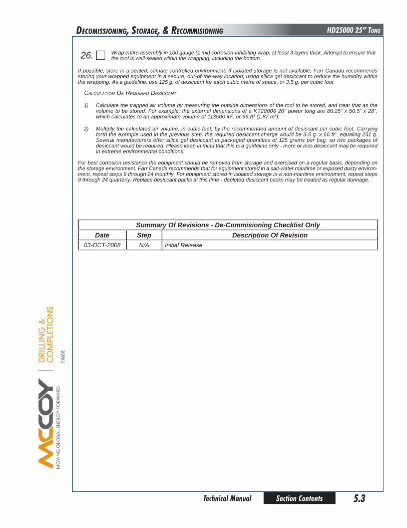
DRI
LLIN
G &
CO
MPL
ETIO
NS
FARR
Section Contents 5.3 Technical Manual
HD25000 25” Tong
If possible, store in a sealed, climate controlled environment. If isolated storage is not available, Farr Canada recommends storing your wrapped equipment in a secure, out-of-the-way location, using silica gel desiccant to reduce the humidity within the wrapping. As a guideline, use 125 g. of desiccant for each cubic metre of space, or 3.5 g. per cubic foot.
calculaTion of requireD DesiccanT
1) Calculate the trapped air volume by measuring the outside dimensions of the tool to be stored, and treat that as the volume to be stored. For example, the external dimensions of a KT20000 20” power tong are 80.25” x 50.5” x 28”, which calculates to an approximate volume of 113500 in3, or 66 ft3 (1.87 m3).
2) Multiply the calculated air volume, in cubic feet, by the recommended amount of desiccant per cubic foot. Carrying forth the example used in the previous step, the required desiccant charge would be 3.5 g. x 66 ft3, equaling 231 g. Several manufacturers offer silica gel desiccant in packaged quantities of 125 grams per bag, so two packages of desiccant would be required. Please keep in mind that this is a guideline only - more or less desiccant may be required in extreme environmental conditions.
For best corrosion resistance the equipment should be removed from storage and exercised on a regular basis, depending on the storage environment. Farr Canada recommends that for equipment stored in a salt-water maritime or exposed dusty environ-ment, repeat steps 9 through 24 monthly. For equipment stored in isolated storage in a non-maritime environment, repeat steps 9 through 24 quarterly. Replace desiccant packs at this time - depleted desiccant packs may be treated as regular dunnage.
Summary of Revisions - de-commisioning checklist onlydate Step description of Revision
03-OCT-2008 N/A Initial Release
26. Wrap entire assembly in 100 gauge (1 mil) corrosion-inhibiting wrap, at least 3 layers thick. Attempt to ensure that the tool is well-sealed within the wrapping, including the bottom.
DECoMISSIonIng, SToRagE, & RECoMMISIonIng
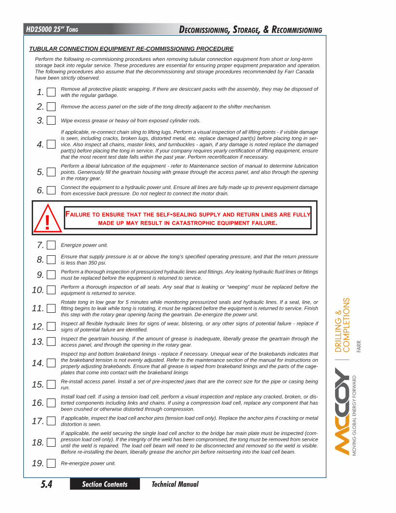
DRI
LLIN
G &
CO
MPL
ETIO
NS
FARR
Section Contents5.4
HD25000 25” Tong
Technical Manual
TubulAR coNNecTIoN equIpMeNT Re-coMMISSIoNING pRoceduRePerform the following re-commisioning procedures when removing tubular connection equipment from short or long-term storage back into regular service. These procedures are essential for ensuring proper equipment preparation and operation. The following procedures also assume that the decommissioning and storage procedures recommended by Farr Canada have been strictly observed.
1. Remove all protective plastic wrapping. If there are desiccant packs with the assembly, they may be disposed of with the regular garbage.
2. Remove the access panel on the side of the tong directly adjacent to the shifter mechanism.
3. Wipe excess grease or heavy oil from exposed cylinder rods.
4. If applicable, re-connect chain sling to lifting lugs. Perform a visual inspection of all lifting points - if visible damage is seen, including cracks, broken lugs, distorted metal, etc. replace damaged part(s) before placing tong in ser-vice. Also inspect all chains, master links, and turnbuckles - again, if any damage is noted replace the damaged part(s) before placing the tong in service. If your company requires yearly certification of lifting equipment, ensure that the most recent test date falls within the past year. Perform recertification if necessary.
5. Perform a liberal lubrication of the equipment - refer to Maintenance section of manual to determine lubrication points. Generously fill the geartrain housing with grease through the access panel, and also through the opening in the rotary gear.
6. Connect the equipment to a hydraulic power unit. Ensure all lines are fully made up to prevent equipment damage from excessive back pressure. Do not neglect to connect the motor drain.
failure to ensure tHat tHe self-sealing supply and return lines are fully made up may result in catastropHic equipment failure.!
7. Energize power unit.
8. Ensure that supply pressure is at or above the tong’s specified operating pressure, and that the return pressure is less than 350 psi.
9. Perform a thorough inspection of pressurized hydraulic lines and fittings. Any leaking hydraulic fluid lines or fittings must be replaced before the equipment is returned to service.
10. Perform a thorough inspection of all seals. Any seal that is leaking or “weeping” must be replaced before the equipment is returned to service.
11. Rotate tong in low gear for 5 minutes while monitoring pressurized seals and hydraulic lines. If a seal, line, or fitting begins to leak while tong is rotating, it must be replaced before the equipment is returned to service. Finish this step with the rotary gear opening facing the geartrain. De-energize the power unit.
12. Inspect all flexible hydraulic lines for signs of wear, blistering, or any other signs of potential failure - replace if signs of potential failure are identified.
13. Inspect the geartrain housing. If the amount of grease is inadequate, liberally grease the geartrain through the access panel, and through the opening in the rotary gear.
14. Inspect top and bottom brakeband linings - replace if necessary. Unequal wear of the brakebands indicates that the brakeband tension is not evenly adjusted. Refer to the maintenance section of the manual for instructions on properly adjusting brakebands. Ensure that all grease is wiped from brakeband linings and the parts of the cage-plates that come into contact with the brakeband linings
15. Re-install access panel. Install a set of pre-inspected jaws that are the correct size for the pipe or casing being run.
16. Install load cell. If using a tension load cell, perform a visual inspection and replace any cracked, broken, or dis-torted components including links and chains. If using a compression load cell, replace any component that has been crushed or otherwise distorted through compression.
17. If applicable, inspect the load cell anchor pins (tension load cell only). Replace the anchor pins if cracking or metal distortion is seen.
18. If applicable, the weld securing the single load cell anchor to the bridge bar main plate must be inspected (com-pression load cell only). If the integrity of the weld has been compromised, the tong must be removed from service until the weld is repaired. The load cell beam will need to be disconnected and removed so the weld is visible. Before re-installing the beam, liberally grease the anchor pin before reinserting into the load cell beam.
19. Re-energize power unit.
DECoMISSIonIng, SToRagE, & RECoMMISIonIng

DRI
LLIN
G &
CO
MPL
ETIO
NS
FARR
Section Contents 5.5 Technical Manual
HD25000 25” Tong
20. Perform a full functional test of the equipment including, if applicable, backup components and float frame com-ponents. Report and correct any hydraulic leaks from the hydraulic valve bank, or from any hydraulic cylinders that are used.
21. If using a frame-mounted tong and backup system, raise the tong off the beams that it is resting upon. Remove the beams and protective cloths - inspect the paint on top of the backup and the bottom of the tong to ensure it has not been damaged by the beam.
22. Test safety door feature (if equipped). Open the tong door(s), and attempt to rotate the cageplate at low speed (low gear) in both directions (makeup and breakout). If cageplate begins rotating, the safety door mechanism is not functional, and the tong must be removed from service until the safety door mechanism can be repaired. If the safety door is operating correctly, cageplate rotation will not be inhibited once the door is closed and latched.
never operate your equipment witH a bypassed or malfunctioning safety door!
23. While rotating the cageplate, ensure that the jaws properly cam. If the jaws do not cam properly, the brakebands need to be tightened. Incremently adjust both the top and bottom brakebands EQUALLY until proper cam action is achieved.
24. When all of the previous steps are completed, you may return your re-commissioned equipment to service.
Summary of Revisions - Re-commisioning checklist onlydate Step description of Revision
03-OCT-2008 N/A Intial Release
DECoMISSIonIng, SToRagE, & RECoMMISIonIng

This page intentionallyleft blank
Section Contents5.6 Technical Manual
HD25000 25” Tong
DRI
LLIN
G &
CO
MPL
ETIO
NS
FARR
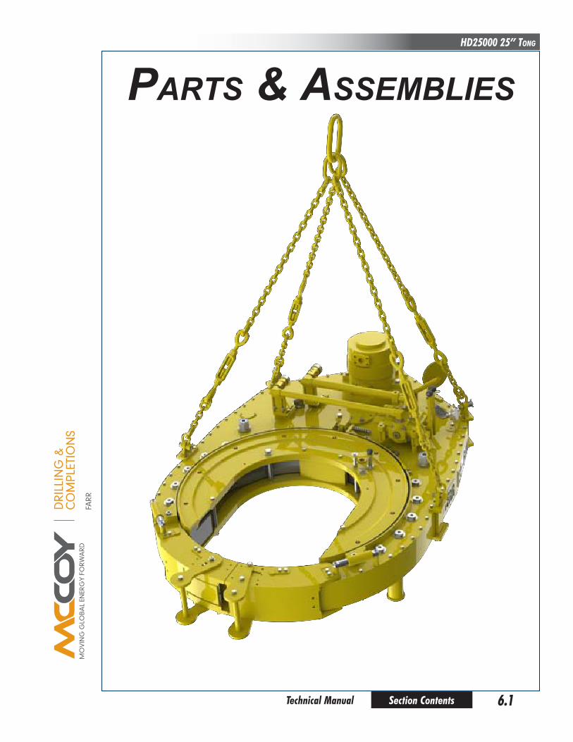
DRI
LLIN
G &
CO
MPL
ETIO
NS
FARR
Section Contents 6.1 Technical Manual
HD25000 25” Tong
partS & aSSemblieS
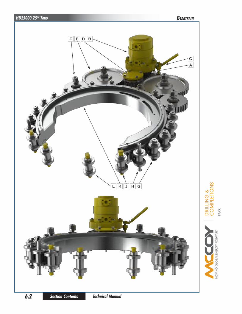
DRI
LLIN
G &
CO
MPL
ETIO
NS
FARR
Section Contents6.2
HD25000 25” Tong
Technical Manual
gEaRTRaIn
F
L K J H G
E D B
CA
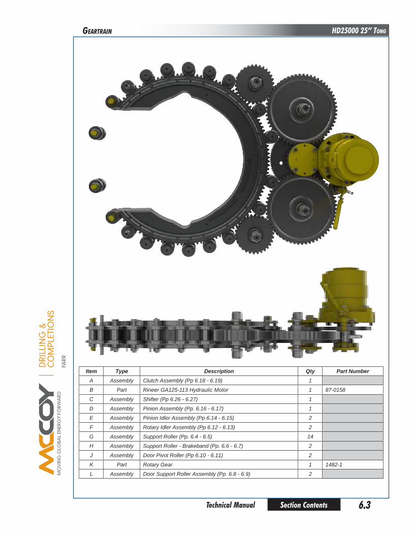
DRI
LLIN
G &
CO
MPL
ETIO
NS
FARR
Section Contents 6.3 Technical Manual
HD25000 25” Tong
Item Type description qty part NumberA Assembly Clutch Assembly (Pp 6.18 - 6.19) 1
B Part Rineer GA125-113 Hydraulic Motor 1 87-0158
C Assembly Shifter (Pp 6.26 - 6.27) 1
D Assembly Pinion Assembly (Pp. 6.16 - 6.17) 1
E Assembly Pinion Idler Assembly (Pp 6.14 - 6.15) 2
F Assembly Rotary Idler Assembly (Pp 6.12 - 6.13) 2
G Assembly Support Roller (Pp. 6.4 - 6.5) 14
H Assembly Support Roller - Brakeband (Pp. 6.6 - 6.7) 2
J Assembly Door Pivot Roller (Pp 6.10 - 6.11) 2
K Part Rotary Gear 1 1482-1
L Assembly Door Support Roller Assembly (Pp. 6.8 - 6.9) 2
gEaRTRaIn

DRI
LLIN
G &
CO
MPL
ETIO
NS
FARR
Section Contents6.4
HD25000 25” Tong
Technical Manual
SuPPoRT RoLLER
A B DC E F D C B G H
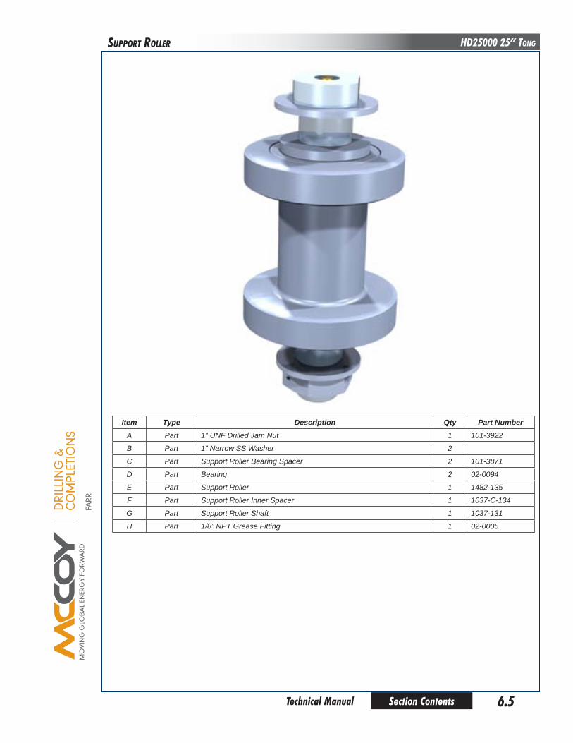
DRI
LLIN
G &
CO
MPL
ETIO
NS
FARR
Section Contents 6.5 Technical Manual
HD25000 25” TongSuPPoRT RoLLER
Item Type description qty part NumberA Part 1” UNF Drilled Jam Nut 1 101-3922
B Part 1” Narrow SS Washer 2
C Part Support Roller Bearing Spacer 2 101-3871
D Part Bearing 2 02-0094
E Part Support Roller 1 1482-135
F Part Support Roller Inner Spacer 1 1037-C-134
G Part Support Roller Shaft 1 1037-131
H Part 1/8” NPT Grease Fitting 1 02-0005

DRI
LLIN
G &
CO
MPL
ETIO
NS
FARR
Section Contents6.6
HD25000 25” Tong
Technical Manual
SuPPoRT RoLLER - bRakEbanD
A B DC E C B F A G
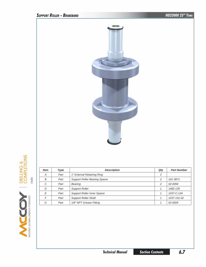
DRI
LLIN
G &
CO
MPL
ETIO
NS
FARR
Section Contents 6.7 Technical Manual
HD25000 25” TongSuPPoRT RoLLER - bRakEbanD
Item Type description qty part NumberA Part 1” External Retaining Ring 2
B Part Support Roller Bearing Spacer 2 101-3871
C Part Bearing 2 02-0094
D Part Support Roller 1 1482-135
E Part Support Roller Inner Spacer 1 1037-C-134
F Part Support Roller Shaft 1 1037-131-02
G Part 1/8” NPT Grease Fitting 1 02-0005
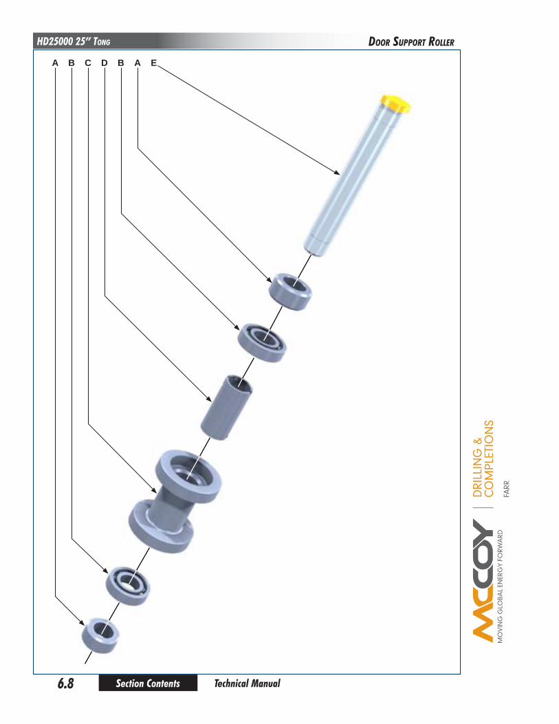
DRI
LLIN
G &
CO
MPL
ETIO
NS
FARR
Section Contents6.8
HD25000 25” Tong
Technical Manual
DooR SuPPoRT RoLLER
A B DC B A E

DRI
LLIN
G &
CO
MPL
ETIO
NS
FARR
Section Contents 6.9 Technical Manual
HD25000 25” TongDooR SuPPoRT RoLLER
Item Type description qty part NumberA Part Door Roller Spacer 2 1482-11-06
B Part 6206LLUC3/2A Bearing 2 02-0096
C Part Support Roller 1 1482-11-03
D Part Door Roller Inner Spacer 2 1482-11-08
E Part Door Support Roller Shaft 1 1482-11-04
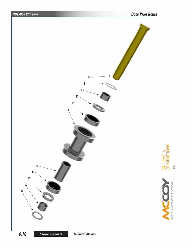
DRI
LLIN
G &
CO
MPL
ETIO
NS
FARR
Section Contents6.10
HD25000 25” Tong
Technical Manual
DooR PIVoT RoLLER
A
B
C
D
E
F
G
E
D
C
B
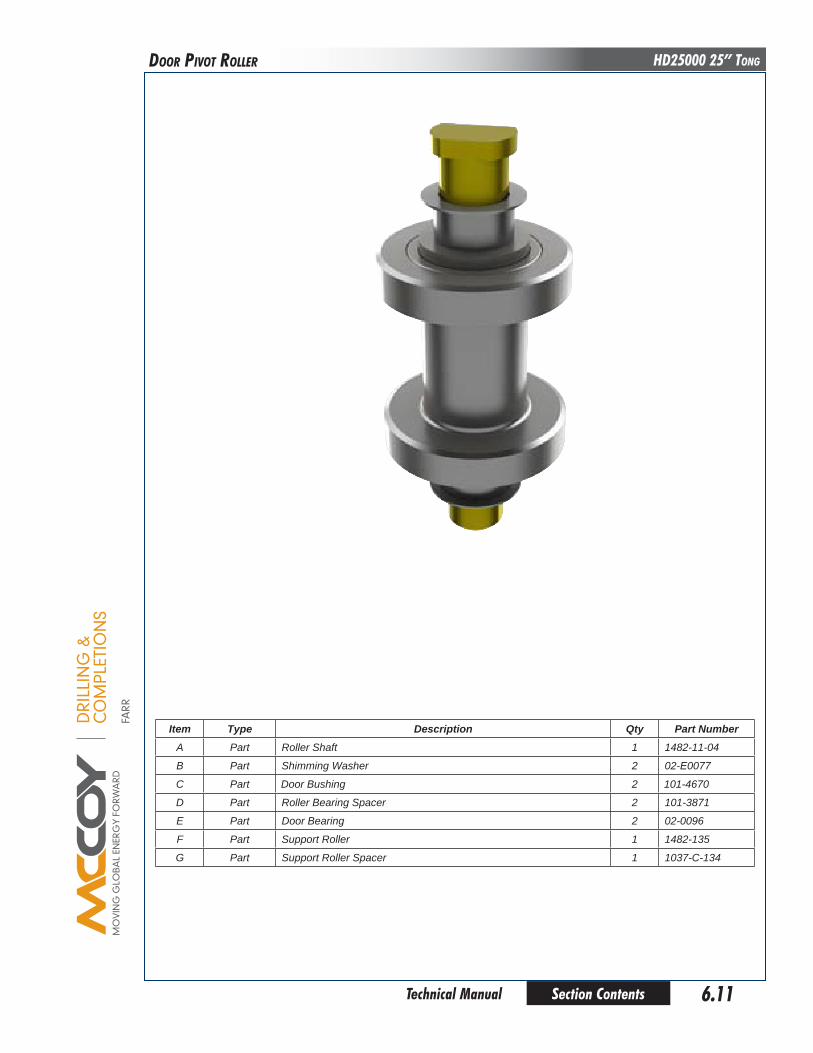
DRI
LLIN
G &
CO
MPL
ETIO
NS
FARR
Section Contents 6.11 Technical Manual
HD25000 25” TongDooR PIVoT RoLLER
Item Type description qty part NumberA Part Roller Shaft 1 1482-11-04
B Part Shimming Washer 2 02-E0077
C Part Door Bushing 2 101-4670
D Part Roller Bearing Spacer 2 101-3871
E Part Door Bearing 2 02-0096
F Part Support Roller 1 1482-135
G Part Support Roller Spacer 1 1037-C-134

DRI
LLIN
G &
CO
MPL
ETIO
NS
FARR
Section Contents6.12
HD25000 25” Tong
Technical Manual
RoTaRy IDLER aSSEMbLy
A B DC E F G F E CH B A J
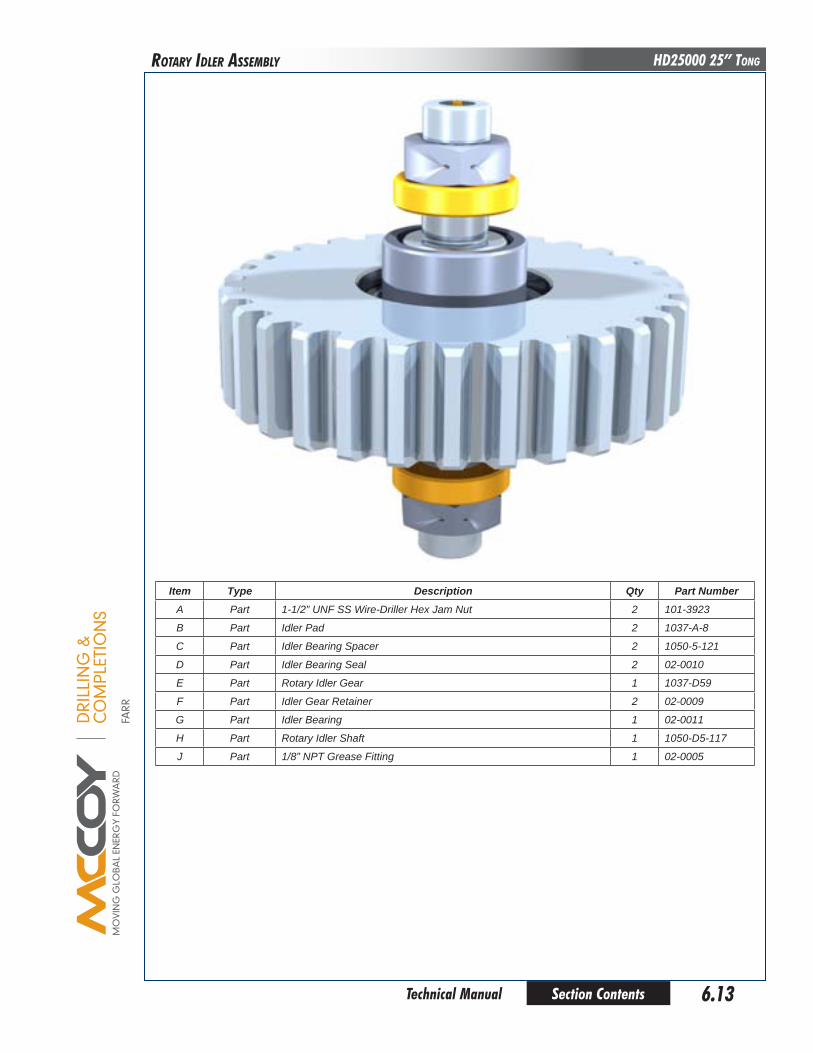
DRI
LLIN
G &
CO
MPL
ETIO
NS
FARR
Section Contents 6.13 Technical Manual
HD25000 25” Tong
Item Type description qty part NumberA Part 1-1/2” UNF SS Wire-Driller Hex Jam Nut 2 101-3923
B Part Idler Pad 2 1037-A-8
C Part Idler Bearing Spacer 2 1050-5-121
D Part Idler Bearing Seal 2 02-0010
E Part Rotary Idler Gear 1 1037-D59
F Part Idler Gear Retainer 2 02-0009
G Part Idler Bearing 1 02-0011
H Part Rotary Idler Shaft 1 1050-D5-117
J Part 1/8” NPT Grease Fitting 1 02-0005
RoTaRy IDLER aSSEMbLy
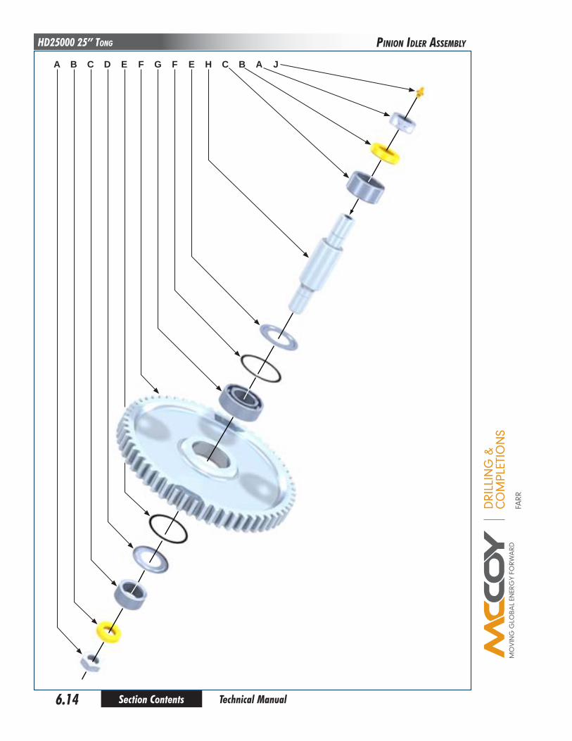
DRI
LLIN
G &
CO
MPL
ETIO
NS
FARR
Section Contents6.14
HD25000 25” Tong
Technical Manual
PInIon IDLER aSSEMbLy
A B DC E F G F E CH B A J

DRI
LLIN
G &
CO
MPL
ETIO
NS
FARR
Section Contents 6.15 Technical Manual
HD25000 25” TongPInIon IDLER aSSEMbLy
Item Type description qty part NumberA Part 1-1/2” UNF SS Wire-Driller Hex Jam Nut 2 101-3923
B Part Idler Pad 2 1037-A-8
C Part Idler Bearing Spacer 2 1050-5-121
D Part Idler Bearing Seal 2 02-0010
E Part Idler Gear Retainer 2 02-0009
F Part Rotary Idler Gear 1 1482-D1
G Part Idler Bearing 1 02-0011
H Part Rotary Idler Shaft 1 1050-D5-117
J Part 1/8” NPT Grease Fitting 1 02-0005
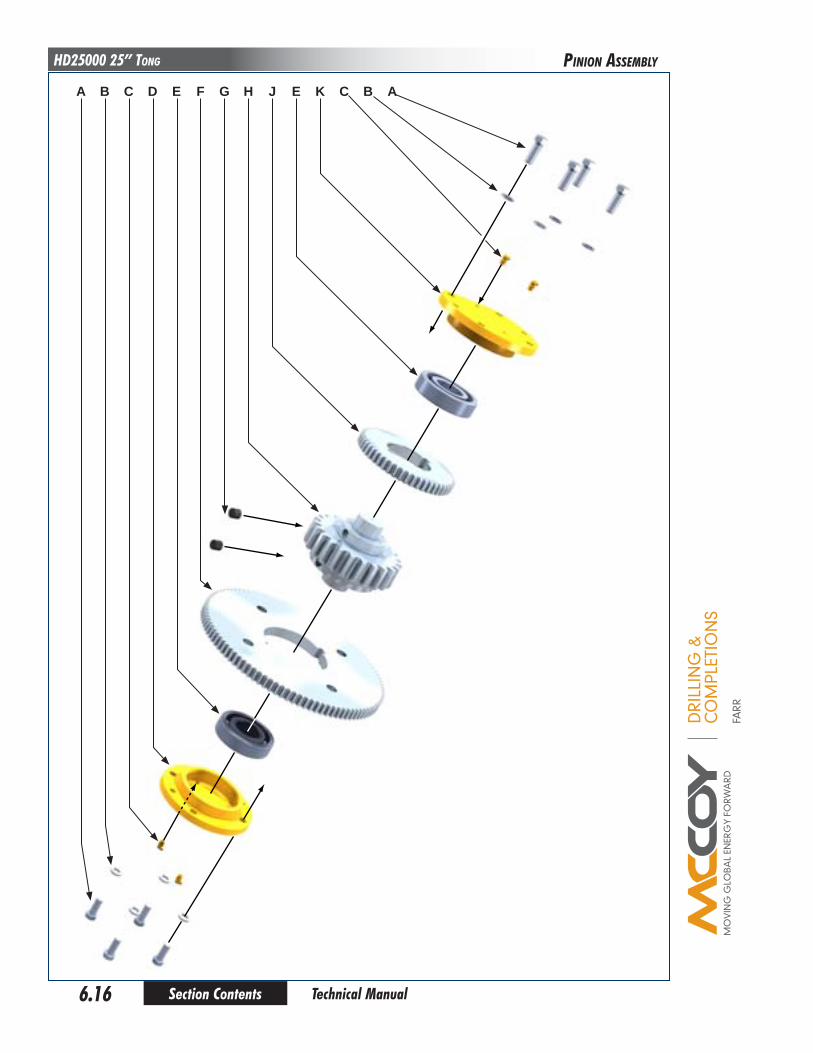
DRI
LLIN
G &
CO
MPL
ETIO
NS
FARR
Section Contents6.16
HD25000 25” Tong
Technical Manual
PInIon aSSEMbLy
A B DC E F G H J KE C B A

DRI
LLIN
G &
CO
MPL
ETIO
NS
FARR
Section Contents 6.17 Technical Manual
HD25000 25” Tong
Item Type description qty part NumberA Part 5/8” NC x 1-3/4” SS Hex Bolt 8
B Part 5/8” NC x 1-3/4” SS Hex Bolt 8
C Part 1/8” NPT 90o Grease Fitting (2 top, 2 bottom) 4 02-0093
D Part Bottom Bearing Cap 1 1037-C-33
E Part Bearing 2 02-0106
F Part Low Pinion Gear 1 1037-D-32
G Part Pinion Gear Key 4 1037-D-15A
H Part Pinion Gear 1 1037-D-15
J Part High Pinion Gear 1 1037-D-12
K Part Top Bearing Cap 1 1037-C-10
PInIon aSSEMbLy

DRI
LLIN
G &
CO
MPL
ETIO
NS
FARR
Section Contents6.18
HD25000 25” Tong
Technical Manual
CLuTCH aSSEMbLy
A B DC E F G H J K
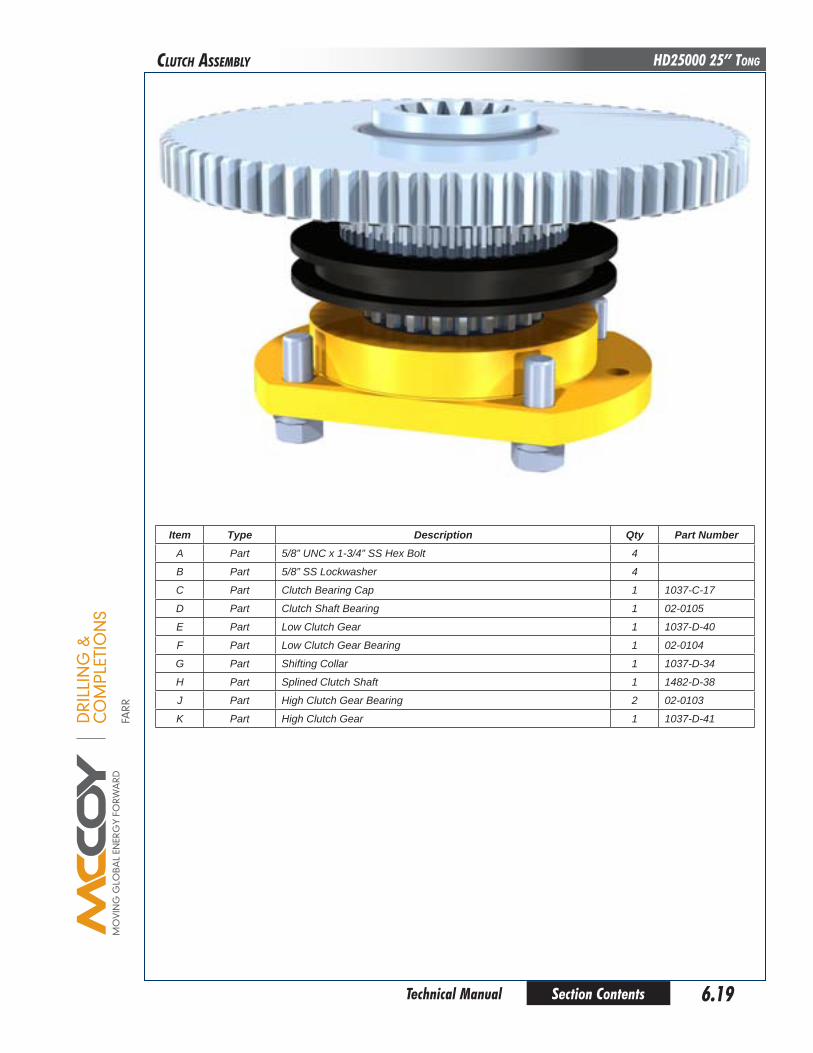
DRI
LLIN
G &
CO
MPL
ETIO
NS
FARR
Section Contents 6.19 Technical Manual
HD25000 25” Tong
Item Type description qty part NumberA Part 5/8” UNC x 1-3/4” SS Hex Bolt 4
B Part 5/8” SS Lockwasher 4
C Part Clutch Bearing Cap 1 1037-C-17
D Part Clutch Shaft Bearing 1 02-0105
E Part Low Clutch Gear 1 1037-D-40
F Part Low Clutch Gear Bearing 1 02-0104
G Part Shifting Collar 1 1037-D-34
H Part Splined Clutch Shaft 1 1482-D-38
J Part High Clutch Gear Bearing 2 02-0103
K Part High Clutch Gear 1 1037-D-41
CLuTCH aSSEMbLy
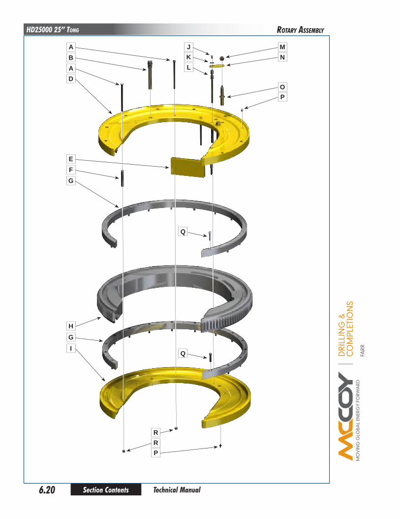
DRI
LLIN
G &
CO
MPL
ETIO
NS
FARR
Section Contents6.20
HD25000 25” Tong
Technical Manual
RoTaRy aSSEMbLy
A JKL
MN
OP
Q
Q
RRP
BAD
EFG
HGI

DRI
LLIN
G &
CO
MPL
ETIO
NS
FARR
Section Contents 6.21 Technical Manual
HD25000 25” Tong
Item Type description qty part NumberA Part 1/2” NC x 8-1/2” Hex Bolt 4 09-1200
B Part Jaw Pivot Bolt 2 1050-C5-28-2
D Part Top Cageplate Weldment 1 101-1842
E Part Rear Cageplate Spacer 1 1482-21-1
F Part Cage Plate Spacer 3 1482-38
G Part Brass Guide RIng 2 1482-23
H Part Rotary Gear 1 1482-1
I Part Bottom Cageplate 1 1482-22
J Part Hex Bolt 3/8”NC x 3/4” 1 09-1044
K Part 3/8” Washer 1 09-5006
L Part Back Cage Plate Bolt 1 1037-36
M Part Backing Pin Knob 1 02-0017
N Part Backing Pin Retainer 1 1482-54
O Part Backing Pin 1 1482-39
P Part 1/8” NPT Grease Fitting 17 02-0005
Q Part Socket Head Cap Screw 1/2” NC x 2-1/4” 30 09-2175
R Part 1/2” NC Nylock Nut 4 09-5610
RoTaRy aSSEMbLy
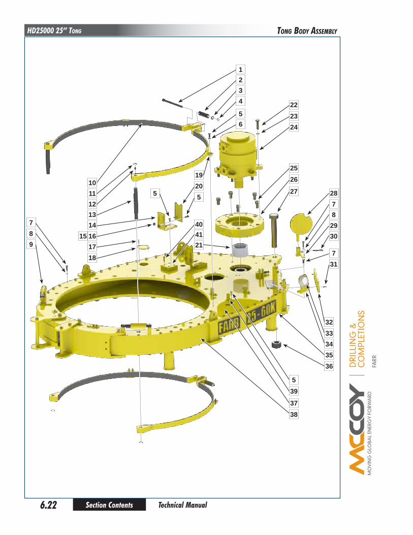
DRI
LLIN
G &
CO
MPL
ETIO
NS
FARR
Section Contents6.22
HD25000 25” Tong
Technical Manual
Tong boDy aSSEMbLy
987
1110
1213
5
17161514
18
38
39
37
5
343332
3536
22
2019
1234
56
5
214140
2324
2526
27 2878
2930
731
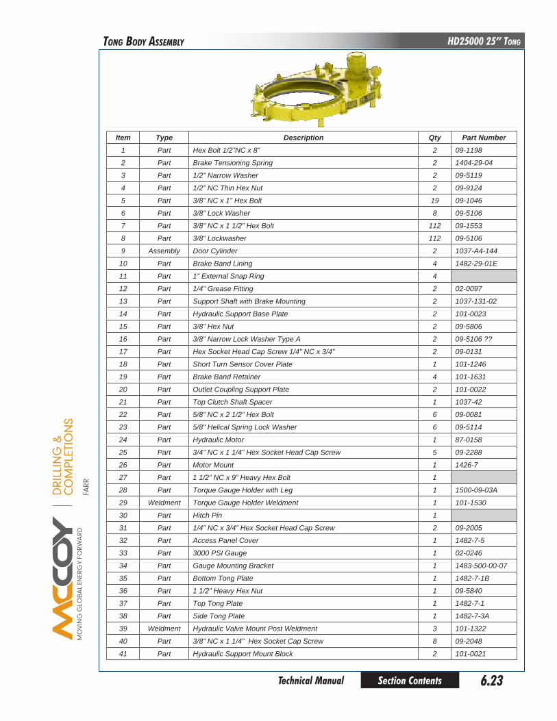
DRI
LLIN
G &
CO
MPL
ETIO
NS
FARR
Section Contents 6.23 Technical Manual
HD25000 25” Tong
Item Type description qty part Number1 Part Hex Bolt 1/2”NC x 8” 2 09-1198
2 Part Brake Tensioning Spring 2 1404-29-04
3 Part 1/2” Narrow Washer 2 09-5119
4 Part 1/2” NC Thin Hex Nut 2 09-9124
5 Part 3/8” NC x 1” Hex Bolt 19 09-1046
6 Part 3/8” Lock Washer 8 09-5106
7 Part 3/8” NC x 1 1/2” Hex Bolt 112 09-1553
8 Part 3/8” Lockwasher 112 09-5106
9 Assembly Door Cylinder 2 1037-A4-144
10 Part Brake Band Lining 4 1482-29-01E
11 Part 1” External Snap Ring 4
12 Part 1/4” Grease Fitting 2 02-0097
13 Part Support Shaft with Brake Mounting 2 1037-131-02
14 Part Hydraulic Support Base Plate 2 101-0023
15 Part 3/8” Hex Nut 2 09-5806
16 Part 3/8” Narrow Lock Washer Type A 2 09-5106 ??
17 Part Hex Socket Head Cap Screw 1/4” NC x 3/4” 2 09-0131
18 Part Short Turn Sensor Cover Plate 1 101-1246
19 Part Brake Band Retainer 4 101-1631
20 Part Outlet Coupling Support Plate 2 101-0022
21 Part Top Clutch Shaft Spacer 1 1037-42
22 Part 5/8” NC x 2 1/2” Hex Bolt 6 09-0081
23 Part 5/8” Helical Spring Lock Washer 6 09-5114
24 Part Hydraulic Motor 1 87-0158
25 Part 3/4” NC x 1 1/4” Hex Socket Head Cap Screw 5 09-2288
26 Part Motor Mount 1 1426-7
27 Part 1 1/2” NC x 9” Heavy Hex Bolt 1
28 Part Torque Gauge Holder with Leg 1 1500-09-03A
29 Weldment Torque Gauge Holder Weldment 1 101-1530
30 Part Hitch Pin 1
31 Part 1/4” NC x 3/4” Hex Socket Head Cap Screw 2 09-2005
32 Part Access Panel Cover 1 1482-7-5
33 Part 3000 PSI Gauge 1 02-0246
34 Part Gauge Mounting Bracket 1 1483-500-00-07
35 Part Bottom Tong Plate 1 1482-7-1B
36 Part 1 1/2” Heavy Hex Nut 1 09-5840
37 Part Top Tong Plate 1 1482-7-1
38 Part Side Tong Plate 1 1482-7-3A
39 Weldment Hydraulic Valve Mount Post Weldment 3 101-1322
40 Part 3/8” NC x 1 1/4” Hex Socket Cap Screw 8 09-2048
41 Part Hydraulic Support Mount Block 2 101-0021
Tong boDy aSSEMbLy
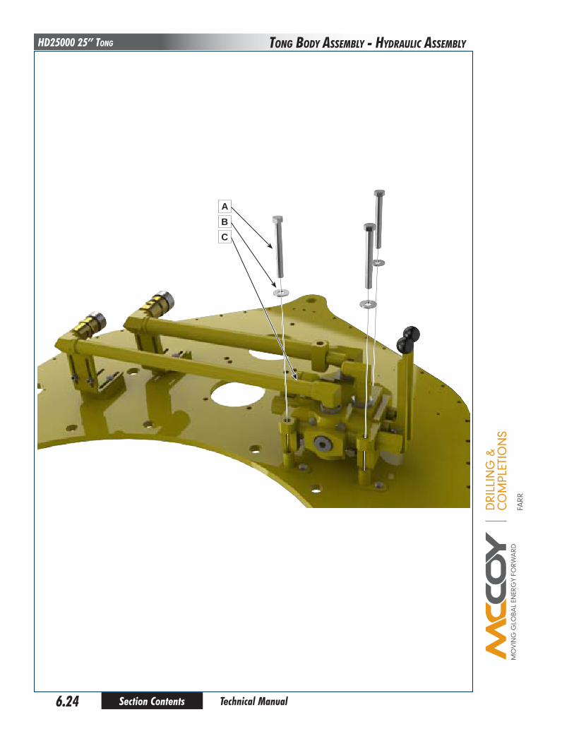
DRI
LLIN
G &
CO
MPL
ETIO
NS
FARR
Section Contents6.24
HD25000 25” Tong
Technical Manual
Tong boDy aSSEMbLy - HyDRauLIC aSSEMbLy
ABC

DRI
LLIN
G &
CO
MPL
ETIO
NS
FARR
Section Contents 6.25 Technical Manual
HD25000 25” TongTong boDy aSSEMbLy - HyDRauLIC aSSEMbLy
Item Type description qty part NumberA Part 1/2” NC x 4-1/2” Hex Bolt 3 09-1184
B Part 1/2” Plain Narrow Flatwasher 3 09-5119
C Assembly Hydraulic Valve Assembly 1 101-1612

DRI
LLIN
G &
CO
MPL
ETIO
NS
FARR
Section Contents6.26
HD25000 25” Tong
Technical Manual
SHIfTER aSSEMbLy
A
F
B
GH
HJKL
CDE
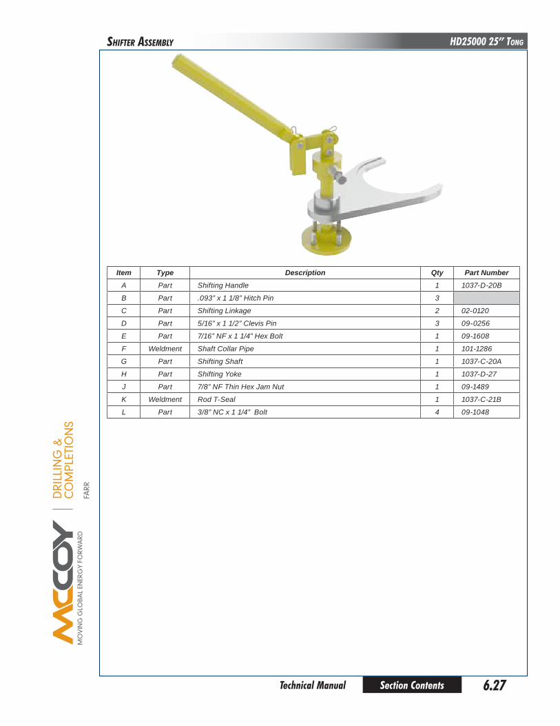
DRI
LLIN
G &
CO
MPL
ETIO
NS
FARR
Section Contents 6.27 Technical Manual
HD25000 25” TongSHIfTER aSSEMbLy
Item Type description qty part NumberA Part Shifting Handle 1 1037-D-20B
B Part .093” x 1 1/8” Hitch Pin 3
C Part Shifting Linkage 2 02-0120
D Part 5/16” x 1 1/2” Clevis Pin 3 09-0256
E Part 7/16” NF x 1 1/4” Hex Bolt 1 09-1608
F Weldment Shaft Collar Pipe 1 101-1286
G Part Shifting Shaft 1 1037-C-20A
H Part Shifting Yoke 1 1037-D-27
J Part 7/8” NF Thin Hex Jam Nut 1 09-1489
K Weldment Rod T-Seal 1 1037-C-21B
L Part 3/8” NC x 1 1/4” Bolt 4 09-1048

DRI
LLIN
G &
CO
MPL
ETIO
NS
FARR
Section Contents6.28
HD25000 25” Tong
Technical Manual
CHaIn SLIng
A
DEF
GH
IJ
BC

DRI
LLIN
G &
CO
MPL
ETIO
NS
FARR
Section Contents 6.29 Technical Manual
HD25000 25” TongCHaIn SLIng
Item Type description qty part NumberA Part Linkage 1 02-0517-1
B Part Linkage 2 02-0517-2
C Part Chain 4 101-0376
D Assembly 3/8” Hammerlok 16 02-0607
E Assembly 3/4” x 6” Eye to Eye Turnbuckle 4 02-6506
F Part Chain 4 101-0378
G Part Shackle 4 ??
H Part Bolt 4 ??
I Part 3/4” Hex Nut 4 09-5818
J Part 3/16” x 1 1/4” Cotter Pin 4
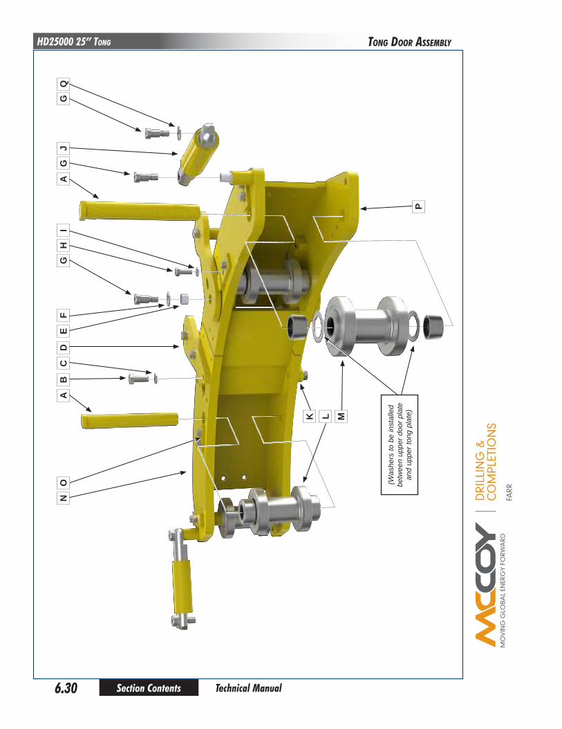
DRI
LLIN
G &
CO
MPL
ETIO
NS
FARR
Section Contents6.30
HD25000 25” Tong
Technical Manual
Tong DooR aSSEMbLy
AN
OB
CD
EF
GQ
GH
IA
JG
LK
P
M
(Was
hers
to b
e in
stal
led
betw
een
uppe
r doo
r pla
te
and
uppe
r ton
g pl
ate)

DRI
LLIN
G &
CO
MPL
ETIO
NS
FARR
Section Contents 6.31 Technical Manual
HD25000 25” Tong
Item Type description qty part NumberA Part Door Roller Support Shaft 2 1482-11-04
B Part 1/2” NC x 1 1/4” Hex Bolt 6 09-1168
C Part 1/2” Lock Washer 6 09-5110
D Part Handle Plate 1 1482-11B-06
E Part Bushing 2 02-0520
F Part 9/16” Washer 1 09-5110
G Part 5/8” x 3/4” Hex Socket Head Shoulder Screw 6 09-0049
H Part 3/8” NC x 1” Hex Bolt 8 09-1046
I Part 3/8” Lock Washer 8 09-5106
J Assembly Door Cylinder 2 1037-A4-144
K Weldment Door Handle Weldment 1 101-1926
L Assembly Door Support Roller Assembly (see Pp 6.8 - 6.9) 2 101-1469
M Assembly Door Pivot Roller (see Pp 6.10 - 6.11) 2 101-1648
N Weldment LH Door 1 1482-11B-00M
O Part Pin Lock 4 1482-11-05
P Weldment RH Door 1 1482-11A-00M
Q Part 1/2” Washer 2 09-5120
R Part Door Bushing 2 101-4670
Tong DooR aSSEMbLy
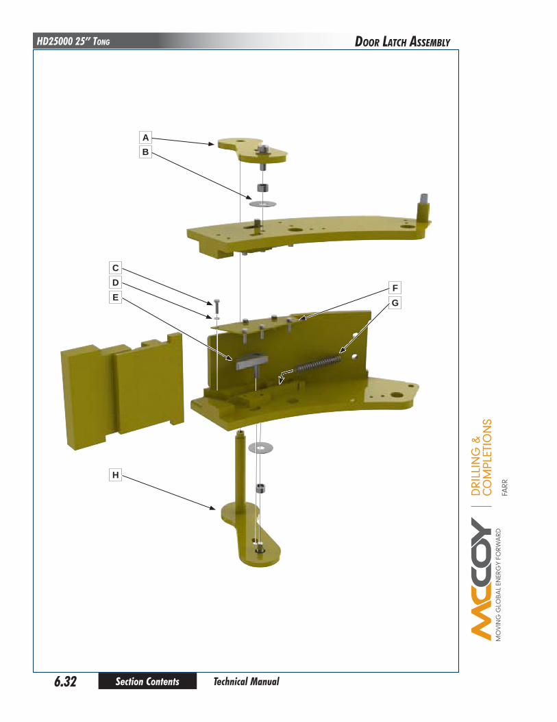
DRI
LLIN
G &
CO
MPL
ETIO
NS
FARR
Section Contents6.32
HD25000 25” Tong
Technical Manual
DooR LaTCH aSSEMbLy
CDE
H
FG
AB
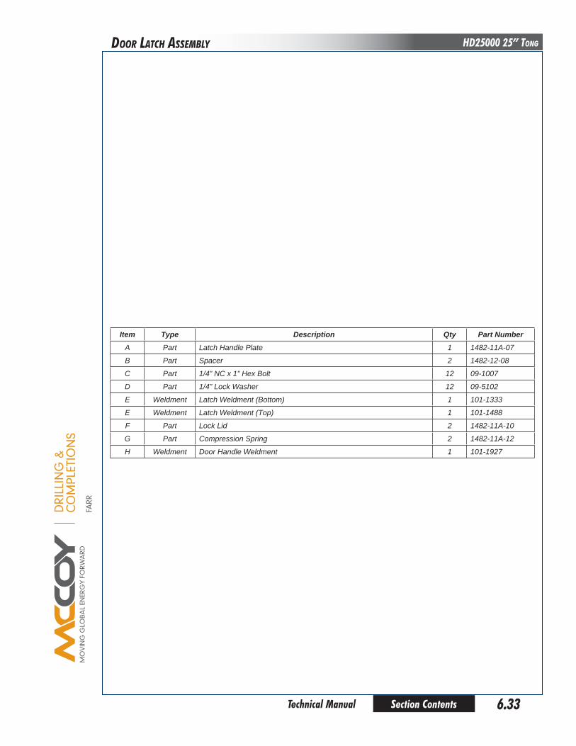
DRI
LLIN
G &
CO
MPL
ETIO
NS
FARR
Section Contents 6.33 Technical Manual
HD25000 25” TongDooR LaTCH aSSEMbLy
Item Type description qty part NumberA Part Latch Handle Plate 1 1482-11A-07
B Part Spacer 2 1482-12-08
C Part 1/4” NC x 1” Hex Bolt 12 09-1007
D Part 1/4” Lock Washer 12 09-5102
E Weldment Latch Weldment (Bottom) 1 101-1333
E Weldment Latch Weldment (Top) 1 101-1488
F Part Lock Lid 2 1482-11A-10
G Part Compression Spring 2 1482-11A-12
H Weldment Door Handle Weldment 1 101-1927

DRI
LLIN
G &
CO
MPL
ETIO
NS
FARR
Section Contents6.34
HD25000 25” Tong
Technical Manual
SafETy DooR aSSEMbLy
N
O
P
JU
KQ
VR
S T
AB
D
C
EFG
M
HI
J
L

DRI
LLIN
G &
CO
MPL
ETIO
NS
FARR
Section Contents 6.35 Technical Manual
HD25000 25” TongSafETy DooR aSSEMbLy
Item Type description qty part NumberA Part RH Mounting Plate 1 101-1172
B Part Hex Socket Shoulder Screw 3/8” NC x 0.51” 4
C Part 1/2” NC x 1 1/4” Hex Bolt 2 09-1168
D Part Block Safety Door Latch 1 101-1104
E Part 5/16” Hex Nut 2 09-6016
F Part Hex Socket Flat Countersunk Head Cap Screw 3/8” NC x 2” 2
G Part SHCS 3/8” NC x 1 1/2” 2 09-2051
H Part Valve Lock Nut 1
I Part Block Safety Door Latch 1 101-1103
J Part Safety Door Side Load Plunger 1 AE12-306
K Part Hex Bolt 3/8” NC x 7/8” 2 09-5125
L Part Hex Socket Head Cap Screw 3/8” NC x 3/4” 4 09-2044
M Part Safety Door Guard
N Part Hex Bolt 1/2” NC x 1” 2 09-1166
O Part Hex Bolt 3/8” NC x 2 1/4” 4 09-1055
P Part 3/8” Regular Lock Washer 4 09-5106
Q Part Deltrol Valve GI21S 1 08-0337
R Part Safety Switch Mount Spacer 1 101-1173
S Part Safety Switch Mount Spacer 1 101-2142
T Part Safety Switch Mount Spacer 1 101-1176
U Part Safety Switch Mount Spacer 1 101-1173
V Part 1/4” NPT JIC 90° Elbow 2 2024-4-4

This page intentionallyleft blank
Section Contents6.36 Technical Manual
HD25000 25” Tong
DRI
LLIN
G &
CO
MPL
ETIO
NS
FARR

DRI
LLIN
G &
CO
MPL
ETIO
NS
FARR
Section Contents 7.1 Technical Manual
HD25000 25” TongToRquE MEaSuREMEnT SECTIon
Type description qty part NumberAssembly 55” Arm 70K Tension Load Cell and Torque Gauge Assembly 1 10-0082T
Assembly Tension Load Cell 1 10-0008T
Part Torque Gauge, 70000 Lbs-Ft. 1 10-0082G
Part Street Elbow 1 08-0304
Part FPT Tee 1 08-0903
Part Nipple Ext Pipe / Ext Pipe 4-4S 1 08-0190
Part 1” Plain Narrow Washer 1 09-5120
Part 5 Ft. Hose Assembly 1 02-0069

DRI
LLIN
G &
CO
MPL
ETIO
NS
FARR
Section Contents7.2
HD25000 25” Tong
Technical Manual
ToRquE MEaSuREMEnT SECTIon
BC
H
E DFG A
L
K
J
M
N

DRI
LLIN
G &
CO
MPL
ETIO
NS
FARR
Section Contents 7.3 Technical Manual
HD25000 25” TongToRquE MEaSuREMEnT SECTIon
Item Type description qty part NumberAssembly Tension Load Cell, 4.08 in2 1 10-0008T
A Part Load Cell End 1 LC99-003
B Part Flange Gasket 1 02-0073
C Part O-Ring 1 02-0350
D Part O-Ring 1 08-0596
E Part Load Cell Piston 1 LC99-101
F Part 3/8” NC x 3/8” Cup Point Hex Set Screw 2
G Part 1/4” MNPT x 3/8” FNPT Street Elbow 1 08-0304
H Part Load Cell Body 1 LC99-104
J Part O-Ring 1 02-0800
K Part Wiper 1 08-1558
L Part Load Cell Rod 1 LC99-002
M Part Stat-O-Seal 1 02-0307
N Part 1/4” NC x 1/2” Cross Recessed Binding Head Machine Screw

DRI
LLIN
G &
CO
MPL
ETIO
NS
FARR
Section Contents7.4
HD25000 25” Tong
Technical Manual
ToRquE MEaSuREMEnT SECTIon
TRoubleShooTING Under normal operating conditions, and with proper maintenance, the torque gauge and load cell system are designed to give lasting trouble-free performance. Faulty indication on the gauge will very often define a fault within the gauge.
IF TROUBLESHOOTING REVEALS THAT THERE IS INSUFFICIENT FLUID IN THE SYSTEM, BEFORE RECHARGING, CHECK THAT ALL SYSTEM COMPONENTS ARE FREE FROM DAMAGE. THIS
WILL ENSURE THAT FLUID LOSS WILL NOT CONTINUE AFTER RELOADING.
* 1. PROBLEM: No indication on gauge. POSSIBLE SOLUTIONS: Obstruction in hose. Loss of hydraulic fluid. Gauge internal mechanism damaged.
2. PROBLEM: Gauge indication too high. POSSIBLE SOLUTIONS: Excessive hydraulic fluid. Internal mechanism of gauge is damaged. Gauge is out of tolerance and may require calibration
3. PROBLEM: Gauge indication too low. POSSIBLE SOLUTIONS: Insufficient hydraulic fluid.7 Gauge internal mechanism damaged. Gauge is out of tolerance and may require calibration
4. PROBLEM: Erratic or sluggish gauge indication. POSSIBLE SOLUTIONS: Pointer rubbing glass or dial. Insufficient hydraulic fluid. Dirty gauge movement. Improper pointer damper adjustment. Gauge internal mechanism damaged. Gauge is out of tolerance and may require calibration
DRI
LLIN
G &
CO
MPL
ETIO
NS
FARR
Section Contents 7.5 Technical Manual
HD25000 25” TongToRquE MEaSuREMEnT SECTIon
peRIodIc INSpecTIoN ANd MAINTeNANce
A. Tong Torque Systems are built to give years of trouble-free service with minimum maintenance. Periodic inspections of the load cell, and hydraulic lines and fittings, are recommended in order to keep the system in top operating condition. A thorough inspection should be made at each rig-up.
B. Recharge hydraulic system with W15/16 fluid via the filling connection at the top of the indicating gauge. Recharging must only be performed when there is no load on the load cell. Procedure:
1. Connect hand pump to filling connection on gauge.
2. Fill hand pump bowl with W15/16 hydraulic fluid and pump fluid into the system until the piston rod on the load cell extends no more than 1/2” from the body. 3. Loosen vent screw on load cell body to permit trapped air to escape during loading.
MAINTAIN GREATER-THAN HALF FULL FLUID LEVEL IN THE HAND PUMP BOWL TO AVOID PUMPING AIR INTO THE SYSTEM. DO NOT
ALLOW THE LEVEL TO FALL BELOW ONE-HALF FULL* 4. Retighten load cell vent screw when the system has been adequately recharged
C. Load cell and indicator gauge should be returned to authorized repair facility for any repairs or calibration required.

This page intentionallyleft blank
Section Contents7.6 Technical Manual
HD25000 25” Tong
DRI
LLIN
G &
CO
MPL
ETIO
NS
FARR
ToRquE MEaSuREMEnT SECTIon
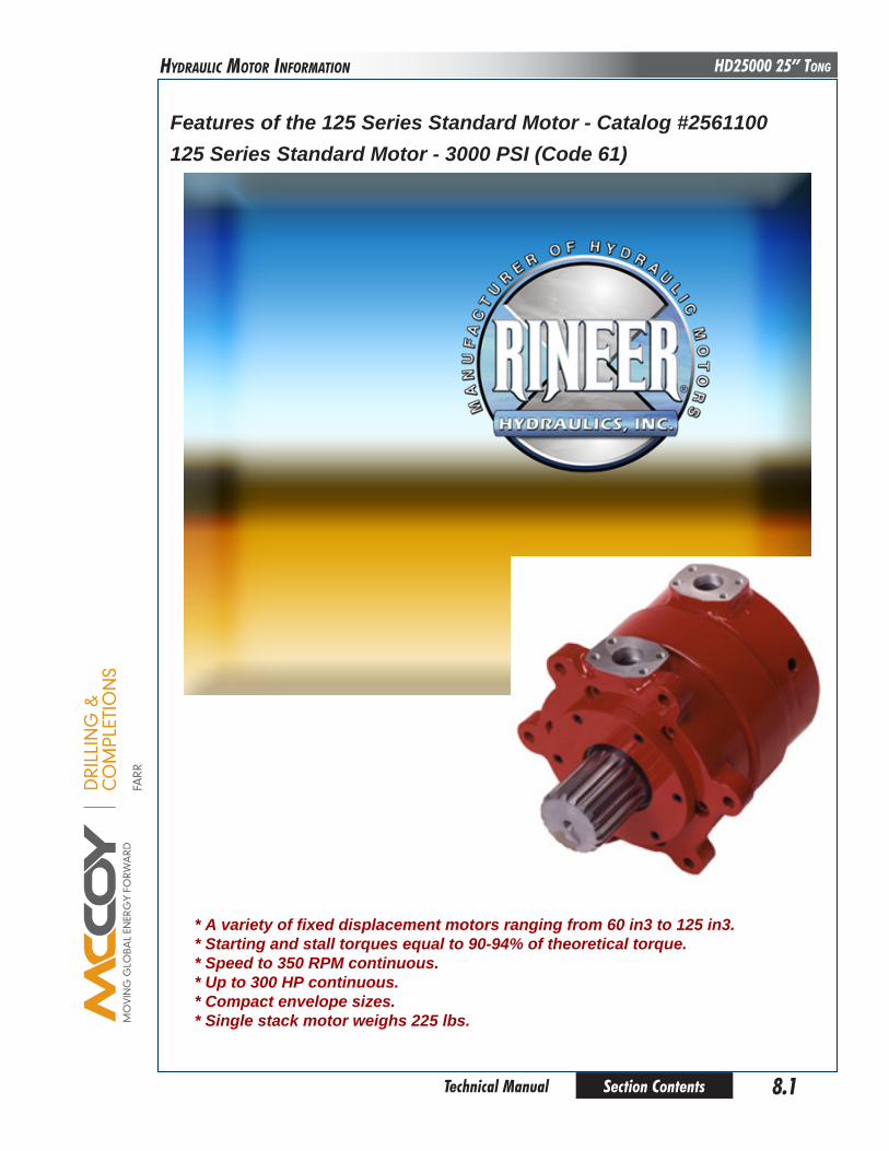
DRI
LLIN
G &
CO
MPL
ETIO
NS
FARR
Section Contents 8.1 Technical Manual
HD25000 25” TongHyDRauLIC MoToR InfoRMaTIon
Features of the 125 Series Standard Motor - catalog #2561100125 Series Standard Motor - 3000 pSI (code 61)
* A variety of fixed displacement motors ranging from 60 in3 to 125 in3. * Starting and stall torques equal to 90-94% of theoretical torque. * Speed to 350 RpM continuous. * up to 300 hp continuous. * compact envelope sizes. * Single stack motor weighs 225 lbs.
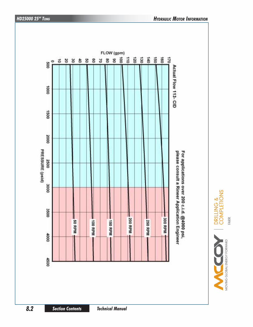
DRI
LLIN
G &
CO
MPL
ETIO
NS
FARR
Section Contents8.2
HD25000 25” Tong
Technical Manual
HyDRauLIC MoToR InfoRMaTIon

DRI
LLIN
G &
CO
MPL
ETIO
NS
FARR
Section Contents 8.3 Technical Manual
HD25000 25” TongHyDRauLIC MoToR InfoRMaTIon
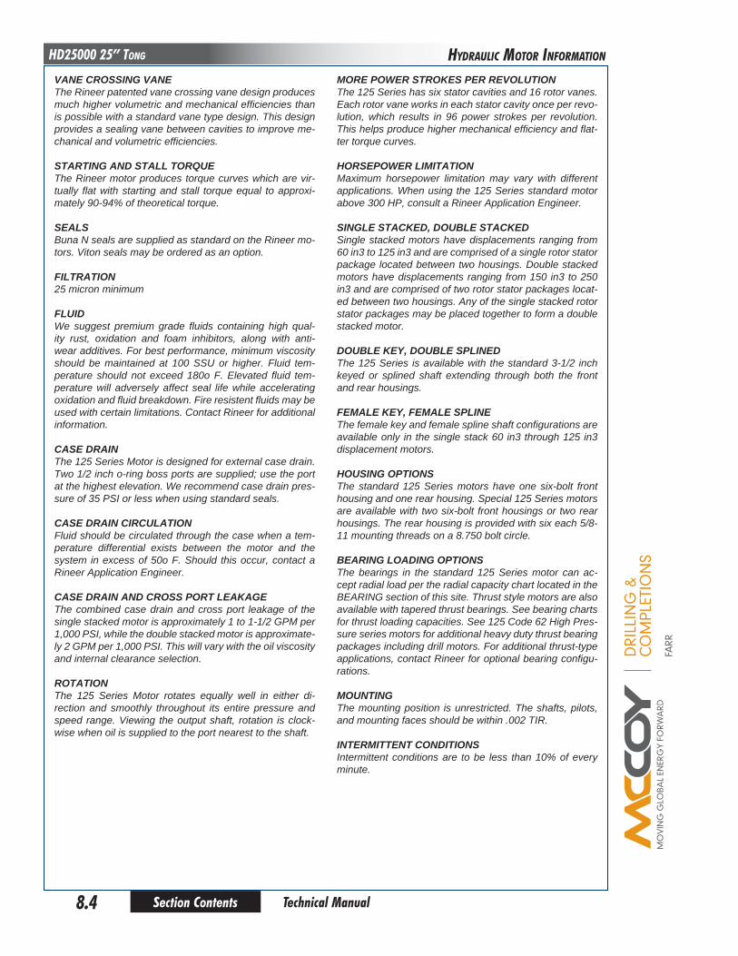
DRI
LLIN
G &
CO
MPL
ETIO
NS
FARR
Section Contents8.4
HD25000 25” Tong
Technical Manual
MoRe poWeR STRoKeS peR RevoluTIoNThe 125 Series has six stator cavities and 16 rotor vanes. Each rotor vane works in each stator cavity once per revo-lution, which results in 96 power strokes per revolution. This helps produce higher mechanical efficiency and flat-ter torque curves.
hoRSepoWeR lIMITATIoNMaximum horsepower limitation may vary with different applications. When using the 125 Series standard motor above 300 HP, consult a Rineer Application Engineer.
SINGle STAcKed, double STAcKedSingle stacked motors have displacements ranging from 60 in3 to 125 in3 and are comprised of a single rotor stator package located between two housings. Double stacked motors have displacements ranging from 150 in3 to 250 in3 and are comprised of two rotor stator packages locat-ed between two housings. Any of the single stacked rotor stator packages may be placed together to form a double stacked motor.
double Key, double SplINedThe 125 Series is available with the standard 3-1/2 inch keyed or splined shaft extending through both the front and rear housings.
FeMAle Key, FeMAle SplINeThe female key and female spline shaft configurations are available only in the single stack 60 in3 through 125 in3 displacement motors.
houSING opTIoNSThe standard 125 Series motors have one six-bolt front housing and one rear housing. Special 125 Series motors are available with two six-bolt front housings or two rear housings. The rear housing is provided with six each 5/8-11 mounting threads on a 8.750 bolt circle.
beARING loAdING opTIoNSThe bearings in the standard 125 Series motor can ac-cept radial load per the radial capacity chart located in the BEARING section of this site. Thrust style motors are also available with tapered thrust bearings. See bearing charts for thrust loading capacities. See 125 Code 62 High Pres-sure series motors for additional heavy duty thrust bearing packages including drill motors. For additional thrust-type applications, contact Rineer for optional bearing configu-rations.
MouNTINGThe mounting position is unrestricted. The shafts, pilots, and mounting faces should be within .002 TIR.
INTeRMITTeNT coNdITIoNSIntermittent conditions are to be less than 10% of every minute.
vANe cRoSSING vANeThe Rineer patented vane crossing vane design produces much higher volumetric and mechanical efficiencies than is possible with a standard vane type design. This design provides a sealing vane between cavities to improve me-chanical and volumetric efficiencies.
STARTING ANd STAll ToRqueThe Rineer motor produces torque curves which are vir-tually flat with starting and stall torque equal to approxi-mately 90-94% of theoretical torque.
SeAlSBuna N seals are supplied as standard on the Rineer mo-tors. Viton seals may be ordered as an option.
FIlTRATIoN25 micron minimum
FluIdWe suggest premium grade fluids containing high qual-ity rust, oxidation and foam inhibitors, along with anti-wear additives. For best performance, minimum viscosity should be maintained at 100 SSU or higher. Fluid tem-perature should not exceed 180o F. Elevated fluid tem-perature will adversely affect seal life while accelerating oxidation and fluid breakdown. Fire resistent fluids may be used with certain limitations. Contact Rineer for additional information.
cASe dRAINThe 125 Series Motor is designed for external case drain. Two 1/2 inch o-ring boss ports are supplied; use the port at the highest elevation. We recommend case drain pres-sure of 35 PSI or less when using standard seals.
cASe dRAIN cIRculATIoNFluid should be circulated through the case when a tem-perature differential exists between the motor and the system in excess of 50o F. Should this occur, contact a Rineer Application Engineer.
cASe dRAIN ANd cRoSS poRT leAKAGeThe combined case drain and cross port leakage of the single stacked motor is approximately 1 to 1-1/2 GPM per 1,000 PSI, while the double stacked motor is approximate-ly 2 GPM per 1,000 PSI. This will vary with the oil viscosity and internal clearance selection.
RoTATIoNThe 125 Series Motor rotates equally well in either di-rection and smoothly throughout its entire pressure and speed range. Viewing the output shaft, rotation is clock-wise when oil is supplied to the port nearest to the shaft.
HyDRauLIC MoToR InfoRMaTIon

DRI
LLIN
G &
CO
MPL
ETIO
NS
FARR
Section Contents 8.5 Technical Manual
HD25000 25” TongHyDRauLIC MoToR InfoRMaTIon

This page intentionallyleft blank
Section Contents8.6 Technical Manual
HD25000 25” Tong
DRI
LLIN
G &
CO
MPL
ETIO
NS
FARR

DRI
LLIN
G &
CO
MPL
ETIO
NS
FARR
Section Contents 8.7 Technical Manual
HD25000 25” TongHyDRauLIC MoToR InfoRMaTIon
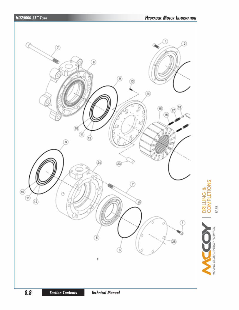
DRI
LLIN
G &
CO
MPL
ETIO
NS
FARR
Section Contents8.8
HD25000 25” Tong
Technical Manual
HyDRauLIC MoToR InfoRMaTIon
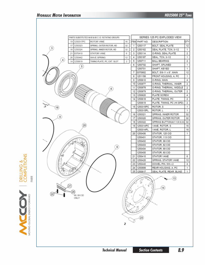
DRI
LLIN
G &
CO
MPL
ETIO
NS
FARR
Section Contents 8.9 Technical Manual
HD25000 25” TongHyDRauLIC MoToR InfoRMaTIon
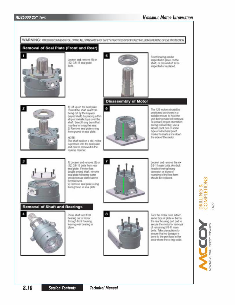
DRI
LLIN
G &
CO
MPL
ETIO
NS
FARR
Section Contents8.10
HD25000 25” Tong
Technical Manual
HyDRauLIC MoToR InfoRMaTIon

DRI
LLIN
G &
CO
MPL
ETIO
NS
FARR
Section Contents 8.11 Technical Manual
HD25000 25” TongHyDRauLIC MoToR InfoRMaTIon
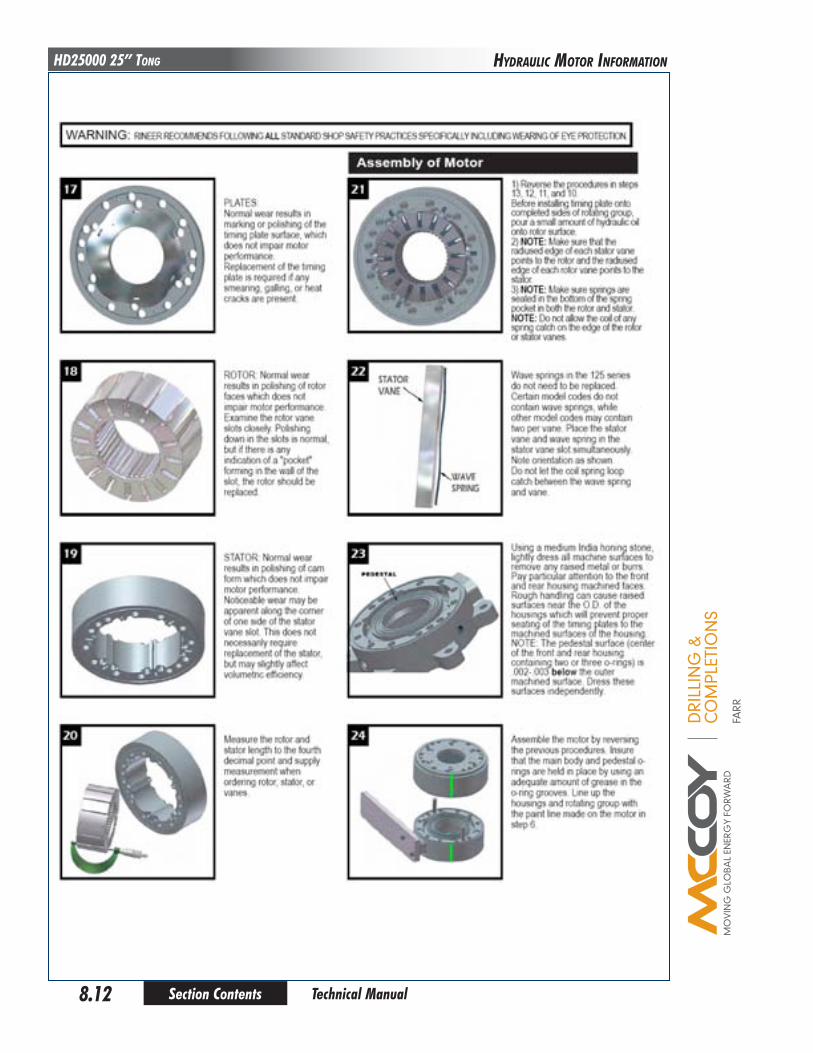
DRI
LLIN
G &
CO
MPL
ETIO
NS
FARR
Section Contents8.12
HD25000 25” Tong
Technical Manual
HyDRauLIC MoToR InfoRMaTIon
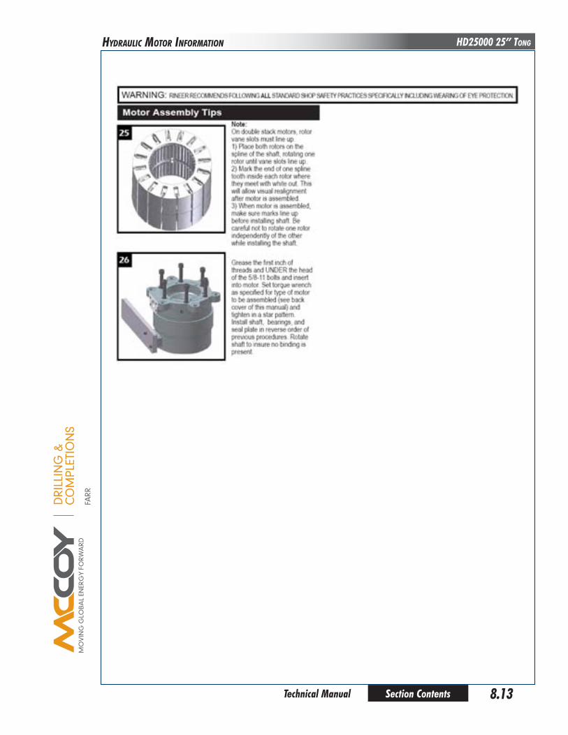
DRI
LLIN
G &
CO
MPL
ETIO
NS
FARR
Section Contents 8.13 Technical Manual
HD25000 25” TongHyDRauLIC MoToR InfoRMaTIon

This page intentionallyleft blank
Section Contents8.14 Technical Manual
HD25000 25” Tong
DRI
LLIN
G &
CO
MPL
ETIO
NS
FARR

DRI
LLIN
G &
CO
MPL
ETIO
NS
FARR
Section Contents APX-1.1 Technical Manual
HD25000 25” Tong
daily inSpection & maintenance cHeckliSt (power tong)
Farr Canada recommends that the following inspection and maintenance procedures be performed before each use, and at least once per day when the tong is in steady use, in the order in which they are listed.
1. Rotate cageplate/rotary gear until the opening in the rotary gear faces towards the rear of the tong.
do not perform any furtHer actionS or maintenance wHile tHe tong iS con-nected to any Hydraulic power Supply. farr canada recommendS tHat all Hydraulic lineS are fully diSconnected, and reSidual Hydraulic preSSure iS bled off. enSure adequate containment iS in place to prevent environ-mental contamination from reSidual Hydraulic fluid.
!
2.
depreSSurize Hydraulic SyStem in preparation for maintenance:1) Rotate the tong to the “open throat” position. Ensure tong and backup doors (if equipped) are closed. Fully
extend the lift cylinder
2) De-energize the power unit.
3) Repeatedly actuate the tong motor control valve lever IN BOTH DIRECTIONS to dissipate any residual pressure in the valve and motor.
4) Remove the hydraulic SUPPLY line from the equipment.
5) Repeatedly actuate the remaining control valve levers IN BOTH DIRECTIONS to dissipate any residual pressure in the remainder of the hydraulic control system.
7) Disconnect the hydraulic RETURN line from the equipment.
8) Disconnect remaining hoses such as case drains, or lines connected to the turns counter.
Hydraulic preSSureS aS HigH aS operating preSSure may remain trapped in Small areaS of tHe equipment. enSure all maintenance iS carried out by a qualified Service tecHnicican, and tHat adequate perSonal protective
equipment iS uSed to guard againSt preSSure injurieS!
3. Perform an initial wash of the tong in order to remove the majority of dirt and grease build-up. Ensure adequate containment is in place to prevent environmental contamination from residual hydraulic fluid and dirty grease.
4. Remove the access panel on the side of the tong directly adjacent to the shifter mechanism.
5. Use a flashlight to perform a visual inspection of the geartrain through the access panel and the opening of the rotary gear. If gear damage or chips of metal are seen, the tong should be removed from service and overhauled to avoid further damage. Replace access panel when inspection is complete.
6. Perform a visual inspection of all fasteners and protruding body pieces (example: hydraulic valve mounts, inlet & outlet line supports, tong legs, shifter handle pivot lugs). Tighten or replace loose or missing fasteners. Farr Canada recommends that damaged or missing body parts br repaired or replaced as soon as possible.
7. Inspect the jaws and dies. Inspect the jaw roller pins for signs of damage - replace pins if necessary. If the pins are welded in place, replace the entire jaw assembly. Ensure dies are secure in the jaw - replace worn dies if necessary. Ensure that the jaw rollers rotate freely. Check to ensure the size of the loaded jaws match the size of casing or pipe you are running.
8. Perform a visual inspection of all lifting points - if visible damage is seen, including cracks, broken lugs, distorted metal, etc. replace damaged part(s) before placing tong in service. Also inspect all chains, master links, and turn-buckles - again, if any damage is noted replace the damaged part(s) before placing the tong in service.
9. Inspect tong for signs of premature wear, or moving parts that are rubbing (bare metal where there used to be paint is a good indication of wear.
10. Inspect backing pin(s). If cracked, broken, or bent it (they) must be replaced.
aPPEnDIx onE
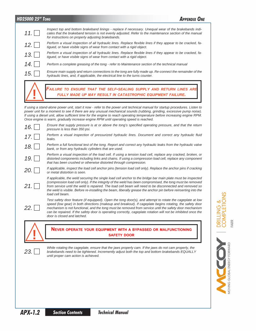
DRI
LLIN
G &
CO
MPL
ETIO
NS
FARR
Section ContentsAPX-1.2
HD25000 25” Tong
Technical Manual
11. Inspect top and bottom brakeband linings - replace if necessary. Unequal wear of the brakebands indi-cates that the brakeband tension is not evenly adjusted. Refer to the maintenance section of the manual for instructions on properly adjusting brakebands.
12. Perform a visual inspection of all hydraulic lines. Replace flexible lines if they appear to be cracked, fa-tigued, or have visible signs of wear from contact with a rigid object.
13. Perform a visual inspection of all hydraulic lines. Replace flexible lines if they appear to be cracked, fa-tigued, or have visible signs of wear from contact with a rigid object.
14. Perform a complete greasing of the tong - refer to Maintenance section of the technical manual
15. Ensure main supply and return connections to the tong are fully made up. Re-connect the remainder of the hydraulic lines, and, if applicable, the electrical line to the turns counter.
failure to enSure tHat tHe Self-Sealing Supply and return lineS are fully made up may reSult in cataStropHic equipment failure.!
If using a stand-alone power unit, start it now - refer to the power unit technical manual for startup procedures. Listen to power unit for a moment to see if there are any unusual mechanical sounds (rubbing, grinding, excessive pump noise). If using a diesel unit, allow sufficient time for the engine to reach operating temperature before increasing engine RPM. Once engine is warm, gradually increase engine RPM until operating speed is reached.
16. Ensure that supply pressure is at or above the tong’s specified operating pressure, and that the return pressure is less than 350 psi.
17. Perform a visual inspection of pressurized hydraulic lines. Document and correct any hydraulic fluid leaks.
18. Perform a full functional test of the tong. Report and correct any hydraulic leaks from the hydraulic valve bank, or from any hydraulic cylinders that are used.
19. Perform a visual inspection of the load cell. If using a tension load cell, replace any cracked, broken, or distorted components including links and chains. If using a compression load cell, replace any component that has been crushed or otherwise distorted through compression.
20. If applicable, inspect the load cell anchor pins (tension load cell only). Replace the anchor pins if cracking or metal distortion is seen.
21. If applicable, the weld securing the single load cell anchor to the bridge bar main plate must be inspected (compression load cell only). If the integrity of the weld has been compromised, the tong must be removed from service until the weld is repaired. The load cell beam will need to be disconnected and removed so the weld is visible. Before re-installing the beam, liberally grease the anchor pin before reinserting into the load cell beam.
22. Test safety door feature (if equipped). Open the tong door(s), and attempt to rotate the cageplate at low speed (low gear) in both directions (makeup and breakout). If cageplate begins rotating, the safety door mechanism is not functional, and the tong must be removed from service until the safety door mechanism can be repaired. If the safety door is operating correctly, cageplate rotation will not be inhibited once the door is closed and latched.
never operate your equipment witH a bypassed or malfunctioning safety door!
23. While rotating the cageplate, ensure that the jaws properly cam. If the jaws do not cam properly, the brakebands need to be tightened. Incremently adjust both the top and bottom brakebands EQUALLY until proper cam action is achieved.
aPPEnDIx onE

DRI
LLIN
G &
CO
MPL
ETIO
NS
FARR
Section Contents APX-2.1 Technical Manual
HD25000 25” Tong
MoNThly MAINTeNANce checKlIST - poWeR ToNG
The following maintenance checklist is intended as a guideline rather than a definitive maintenance schedule. Your equip-ment may require more, or less, maintenance depending upon the frequency of use, the percentage of maximum torque that your equipment is routinely subjected to, and the field conditions under which your equipment operates. Farr Canada recommends that the following inspection and maintenance procedures be performed monthly, or in conjuction with your maintenance foreman’s experience and best estimate of when your equipment is due for this maintenance.
1. Rotate cageplate/rotary gear until the opening in the rotary gear faces towards the rear of the tong.
do not perform any furtHer actionS or maintenance wHile tHe tong iS con-nected to any Hydraulic power Supply. farr canada recommendS tHat all Hydraulic lineS are fully diSconnected, and reSidual Hydraulic preSSure iS bled off. enSure adequate containment iS in place to prevent environ-mental contamination from reSidual Hydraulic fluid.
!
2.
depreSSurize Hydraulic SyStem in preparation for maintenance:i) Ensure tong and backup doors (if equipped) are closed. Fully extend the lift cylinder
ii) De-energize the power unit.
iii) Repeatedly actuate the tong motor control valve lever IN BOTH DIRECTIONS to dissipate any residual pressure in the valve and motor.
iv) Remove the hydraulic SUPPLY line from the equipment.
v) Repeatedly actuate the remaining control valve levers IN BOTH DIRECTIONS to dissipate any residual pressure in the remainder of the hydraulic control system.
vi) Disconnect the hydraulic RETURN line from the equipment.
vii) Disconnect remaining hoses such as case drains, or lines connected to the turns counter - disconnec-tion of hydraulic lines that do not run to the power unit (eg. tong-to-backup lines, safety door lines, etc.) is not required.
Hydraulic preSSureS aS HigH aS operating preSSure may remain trapped in Small areaS of tHe equipment. enSure all maintenance iS carried out by a qualified Service tecHnician, and tHat adequate perSonal protective equip-
ment iS uSed to guard againSt preSSure injurieS!
3. Clean the exterior of the tool thoroughly, using either water (if using a pressure washer ensure a low-pressure wash wand is used), or an appropriate solvent-based grease-cutting cleaner such as Varsol. Ensure adequate containment is in place to prevent environmental contamination from residual hydraulic fluid, dirty grease, and cleaning agents.
4. Remove the access panel on the side of the tong directly adjacent to the shifter mechanism.
5. Clean the interior of the tong thoroughly, using either water (do not use a pressure washer), or an appropriate solvent-based grease-cutting cleaner such as Varsol. Ensure adequate containment is in place to prevent envi-ronmental contamination from residual hydraulic fluid, dirty grease, and cleaning agents. Make a note if any metal shavings or metal pieces are flushed out of the geartrain cavity - if shavings or metal pieces are seen the tong must be overhauled before it is returned to service.
6. Inspect all fasteners and fastener safety wires (if equipped). Replace any missing fasteners - use Grade 8 bolts only unless otherwise specified. Re-torque all external fasteners to SAE specifications.
7. Repair or replace any damaged or missing external body parts, such as torque gauge mounts, hydraulic supports, safety door protectors, etc.
8. Perform a visual inspection of all fasteners and protruding body pieces (example: hydraulic valve mounts, inlet & outlet line supports, tong legs, shifter handle pivot lugs). Tighten or replace loose or missing fasteners. Farr Canada recommends that damaged or missing body parts be repaired or replaced as soon as possible.
9. Inspect tong for signs of premature wear, or moving parts that are rubbing (bare metal where there used to be paint is a good indication of wear.
aPPEnDIx Two
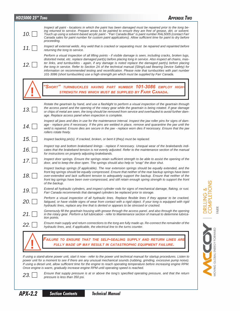
DRI
LLIN
G &
CO
MPL
ETIO
NS
FARR
Section ContentsAPX-2.2
HD25000 25” Tong
Technical Manual
10. Inspect all paint - locations in which the paint has been damaged must be repaired prior to the tong be-ing returned to service. Prepare areas to be painted to ensure they are free of grease, dirt, or solvent. Touch up using a solvent-based acrylic paint - “Farr Canada Blue” is paint number RAL5005 (contact Farr Canada sales for paint number for custom paint applications). Allow sufficient time for paint to dry before proceeding.
11. Inspect all external welds. Any weld that is cracked or separating must be repaired and repainted before returning the tong to service.
12.
Perform a visual inspection of all lifting points - if visible damage is seen, including cracks, broken lugs, distorted metal, etc. replace damaged part(s) before placing tong in service. Also inspect all chains, mas-ter links, and turnbuckles - again, if any damage is noted replace the damaged part(s) before placing the tong in service. Refer to Section 2A of the technical manual (Sling/Load Bearing Device Safety) for information on recommended testing and recertification. Please note that turnbuckles with part number 101-3086 (short turnbuckles) use a high-strength pin which must be supplied by Farr Canada.
“SHort” turnbuckleS Having part number 101-3086 employ HigH-StrengtH pinS wHicH muSt be Supplied by farr canada.!
13. Rotate the geartrain by hand, and use a flashlight to perform a visual inspection of the geartrain through the access panel and the opening of the rotary gear while the geartrain is being rotated. If gear damage or chips of metal are seen, the tong should be removed from service and overhauled to avoid further dam-age. Replace access panel when inspection is complete.
14. Inspect all jaws and dies in use for the maintenance interval. Inspect the jaw roller pins for signs of dam-age - replace pins if necessary. If the pins are welded in place, remove and quarantine the jaw until the weld is repaired. Ensure dies are secure in the jaw - replace worn dies if necessary. Ensure that the jaw rollers rotate freely.
15. Inspect backing pin(s). If cracked, broken, or bent it (they) must be replaced.
16. Inspect top and bottom brakeband linings - replace if necessary. Unequal wear of the brakebands indi-cates that the brakeband tension is not evenly adjusted. Refer to the maintenance section of the manual for instructions on properly adjusting brakebands.
17. Inspect door springs. Ensure the springs retain sufficient strength to be able to assist the opening of the door, and to keep the door open. The springs should also help to “snap” the door shut.
18. Inspect backup springs (if applicable). The rear extension springs should be equally extended, and the front leg springs should be equally compressed. Ensure that neither of the rear backup springs have been over-extended and lack sufficient tension to adequately support the backup. Ensure that neither of the front leg springs have been over-compressed, and still retain enough spring strength to support the front of the backup.
19. Extend all hydraulic cylinders, and inspect cylinder rods for signs of mechanical damage, flaking, or rust. Farr Canada recommends that damaged cylinders be replaced prior to storage.
20. Perform a visual inspection of all hydraulic lines. Replace flexible lines if they appear to be cracked, fatigued, or have visible signs of wear from contact with a rigid object. If your tong is equipped with rigid hydraulic lines, replace any line that is dented or appears to be stressed or cracked.
21. Generously fill the geartrain housing with grease through the access panel, and also through the opening in the rotary gear. Perform a full lubrication - refer to Maintenance section of manual to determine lubrica-tion points.
22. Ensure main supply and return connections to the tong are fully made up. Re-connect the remainder of the hydraulic lines, and, if applicable, the electrical line to the turns counter.
failure to enSure tHat tHe Self-Sealing Supply and return lineS are fully made up may reSult in cataStropHic equipment failure.!
If using a stand-alone power unit, start it now - refer to the power unit technical manual for startup procedures. Listen to power unit for a moment to see if there are any unusual mechanical sounds (rubbing, grinding, excessive pump noise). If using a diesel unit, allow sufficient time for the engine to reach operating temperature before increasing engine RPM. Once engine is warm, gradually increase engine RPM until operating speed is reached.
23. Ensure that supply pressure is at or above the tong’s specified operating pressure, and that the return pressure is less than 350 psi.
aPPEnDIx Two

DRI
LLIN
G &
CO
MPL
ETIO
NS
FARR
Section Contents APX-2.3 Technical Manual
HD25000 25” Tong
24. Perform a visual inspection of pressurized hydraulic lines. If any hydraulic fittings or hoses are leaking they must be repaired or replaced before proceeding.
25. Rotate tong for one minute, stop, and reverse the direction of rotation for another minute, ending with the opening of the rotary gear facing the geartrain. De-energize the power unit, and perform another generous lubrication of the geartrain, including the gear housing.
26. Energize power unit. Rotate tong for one minute, stop, and reverse the direction of rotation for another minute, ending with the opening of the rotary gear facing the geartrain.
27. De-energize the power unit, and perform a third generous lubrication of the geartrain, including the gear housing.
28. Re-energize power unit and extend all hydraulic cylinders. Inspect cylinder rods for signs of mechanical damage, flaking, or rust. Farr Canada recommends that damaged cylinders be replaced.
29. Rotate tong in low gear for 5 minutes while monitoring pressurized seals and hydraulic lines. If a seal, line, or fitting begins to leak while tong is rotating, it must be replaced before the equipment is returned to service.
30. Rotate tong in high gear for 5 minutes while monitoring temperature of top and bottom bearing caps. If the bearing caps are hot to the touch (higher than approximately 50oC) replace the applicable bearings. Likewise if the tong is making unusual noises check for damaged bearings (see Maintenance Manual for all bearing locations).
31. Install load cell. If using a tension load cell, perform a visual inspection and replace any cracked, broken, or distorted components including links and chains. If using a compression load cell, replace any compo-nent that has been crushed or otherwise distorted through compression.
32. If applicable, inspect the load cell anchor pins (tension load cell only). Replace the anchor pins if cracking or metal distortion is seen.
33. If applicable, the weld securing the single load cell anchor to the bridge bar main plate must be inspected (compression load cell only). If the integrity of the weld has been compromised, the tong must be removed from service until the weld is repaired. The load cell beam will need to be disconnected and removed so the weld is visible. Before re-installing the beam, liberally grease the anchor pin before reinserting into the load cell beam.
34. Inspect load cell for damage or signs of stress. Check oil level in load cell and fill if necessary (refer to technical manual Section 7 or Section 8).
35. While rotating the cageplate, ensure that the jaws properly cam. If the jaws do not cam properly, the brakebands need to be tightened. Incremently adjust both the top and bottom brakebands EQUALLY until proper cam action is achieved. Refer to the maintenance section of the manual for instructions on properly adjusting brakebands.
36. Perform a full functional test of the tong including, if applicable, backup components, lift cylinder, and float frame components. Report and correct any hydraulic leaks from the hydraulic valve bank, or from any hydraulic cylinders that are used.
37. Test safety door feature (if equipped). Begin rotating the tong at low speed, and open the tong door(s). If rotation does not immediately stop, this is an indication that the safety door mechanism is not operaing correctly and the tong must be removed from service until the mechanism is repaired. Repeat the test while operating the tong in the opposite direction. If the safety door is operating correctly, cageplate rota-tion will not be inhibited once the door is closed and latched.
never operate your equipment witH a bypaSSed or malfunctioning Safety door!
38. Farr Canada recommends that an anti-corrosive agent such as Tectyl® 506 be applied to all external unpainted surfaces (and chain slings) EXCEPT cylinder rods, jaw rollers, and rotary gear camming surfaces. Refer to manufacturer data sheets for proper application and safety information.
once all of the above maintenance checklist items have been satisfactorily completed the tool may be returned to service.
aPPEnDIx Two