technical manual kt8625 - texasinternational.com · kt8625 tong with clincher® backup technical...
TRANSCRIPT
• Specifications• Operation• Maintenance• Assembly
TECHNICAL MANUAL
Copyright © 2005 - 2012 McCoy Corporation. All rights reserved.Published by McCoy Corporation, Technical Publications Department14755 - 121A Avenue • Edmonton, AB, Canada, T5L 2T2
mccoyglobal.com
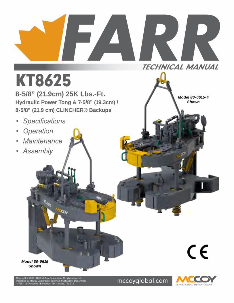
KT86258-5/8” (21.9cm) 25K Lbs.-Ft.Hydraulic Power Tong & 7-5/8” (19.3cm) / 8-5/8” (21.9 cm) CLINCHER® Backups
Model 80-0615-4Shown
Model 80-0615Shown

KT8625 Tong WiTh CLinChER® BaCKup
Section contentS iii technical Manual
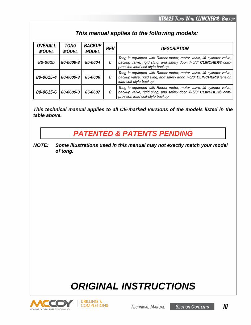
This manual applies to the following models:
NOTE: Some illustrations used in this manual may not exactly match your model of tong.
PATENTED & PATENTS PENDING
oVeRall MoDel
tonG MoDel
BacKuP MoDel ReV DeScRiPtion
80-0615 80-0609-3 85-0604 0Tong isequippedwithRineermotor,motorvalve, liftcylindervalve,backupvalve,rigidsling,andsafetydoor.7-5/8”CLINCHER®com-pressionloadcell-stylebackup.
80-0615-4 80-0609-3 85-0606 0Tong isequippedwithRineermotor,motorvalve, liftcylindervalve,backupvalve,rigidsling,andsafetydoor.7-5/8”CLINCHER®tensionloadcell-stylebackup.
80-0615-6 80-0609-3 85-0607 0Tong isequippedwithRineermotor,motorvalve, liftcylindervalve,backupvalve,rigidsling,andsafetydoor.8-5/8”CLINCHER®com-pressionloadcell-stylebackup.
ORIGINAL INSTRUCTIONS
This technical manual applies to all CE-marked versions of the models listed in the table above.

This page intentionallyleft blank
KT8625 Tong WiTh CLinChER® BaCKup
Section contentS v technical Manual
WARNINGS
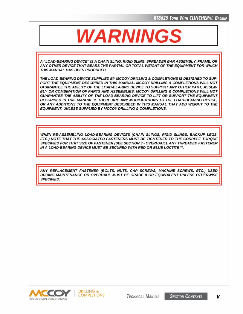
ANY REPLACEMENT FASTENER (BOLTS, NUTS, CAP SCREWS, MACHINE SCREWS, ETC.) USED DURING MAINTENANCE OR OVERHAUL MUST BE GRADE 8 OR EQUIVALENT UNLESS OTHERWISE SPECIFIED.
WHEN RE-ASSEMBLING LOAD-BEARING DEVICES (CHAIN SLINGS, RIGID SLINGS, BACKUP LEGS, ETC.) NOTE THAT THE ASSOCIATED FASTENERS MUST BE TIGHTENED TO THE CORRECT TORQUE SPECIFIED FOR THAT SIZE OF FASTENER (SEE SECTION 3 - OVERHAUL). ANY THREADED FASTENER IN A LOAD-BEARING DEVICE MUST BE SECURED WITH RED OR BLUE LOCTITE™.
A “LOAD-BEARING DEVICE” IS A CHAIN SLING, RIGID SLING, SPREADER BAR ASSEMBLY, FRAME, OR ANY OTHER DEVICE THAT BEARS THE PARTIAL OR TOTAL WEIGHT OF THE EQUIPMENT FOR WHICH THIS MANUAL HAS BEEN PRODUCED
THE LOAD-BEARING DEVICE SUPPLIED BY MCCOY DRILLING & COMPLETIONS IS DESIGNED TO SUP-PORT THE EQUIPMENT DESCRIBED IN THIS MANUAL. MCCOY DRILLING & COMPLETIONS WILL NOT GUARANTEE THE ABILITY OF THE LOAD-BEARING DEVICE TO SUPPORT ANY OTHER PART, ASSEM-BLY OR COMBINATION OF PARTS AND ASSEMBLIES. MCCOY DRILLING & COMPLETIONS WILL NOT GUARANTEE THE ABILITY OF THE LOAD-BEARING DEVICE TO LIFT OR SUPPORT THE EQUIPMENT DESCRIBED IN THIS MANUAL IF THERE ARE ANY MODIFICATIONS TO THE LOAD-BEARING DEVICE, OR ANY ADDITIONS TO THE EQUIPMENT DESCRIBED IN THIS MANUAL THAT ADD WEIGHT TO THE EQUIPMENT, UNLESS SUPPLIED BY MCCOY DRILLING & COMPLETIONS.

This page intentionallyleft blank
KT8625 Tong WiTh CLinChER® BaCKup
Section contentS vii technical Manual
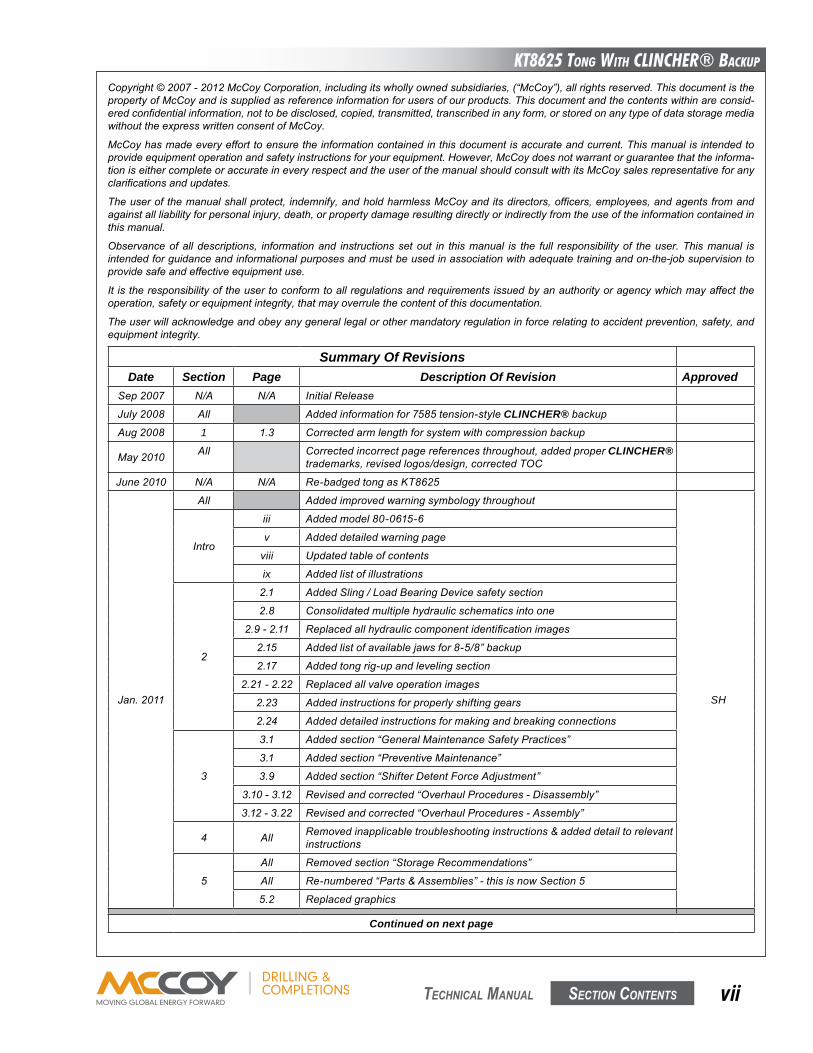
Summary Of RevisionsDate Section Page Description Of Revision Approved
Sep2007 N/A N/A InitialRelease
July2008 All Addedinformationfor7585tension-styleCLINCHER®backupAug2008 1 1.3 Correctedarmlengthforsystemwithcompressionbackup
May2010 All Correctedincorrectpagereferencesthroughout,addedproperCLINCHER®trademarks,revisedlogos/design,correctedTOC
June2010 N/A N/A Re-badgedtongasKT8625
Jan.2011
All Addedimprovedwarningsymbologythroughout
SH
Intro
iii Addedmodel80-0615-6
v Addeddetailedwarningpage
viii Updatedtableofcontents
ix Addedlistofillustrations
2
2.1 AddedSling/LoadBearingDevicesafetysection
2.8 Consolidatedmultiplehydraulicschematicsintoone
2.9-2.11 Replacedallhydrauliccomponentidentificationimages
2.15 Addedlistofavailablejawsfor8-5/8”backup
2.17 Addedtongrig-upandlevelingsection
2.21-2.22 Replacedallvalveoperationimages
2.23 Addedinstructionsforproperlyshiftinggears
2.24 Addeddetailedinstructionsformakingandbreakingconnections
3
3.1 Addedsection“GeneralMaintenanceSafetyPractices”
3.1 Addedsection“PreventiveMaintenance”
3.9 Addedsection“ShifterDetentForceAdjustment”
3.10-3.12 Revisedandcorrected“OverhaulProcedures-Disassembly”
3.12-3.22 Revisedandcorrected“OverhaulProcedures-Assembly”
4 All Removedinapplicabletroubleshootinginstructions&addeddetailtorelevantinstructions
5
All Removedsection“StorageRecommendations”
All Re-numbered“Parts&Assemblies”-thisisnowSection5
5.2 Replacedgraphics
Continued on next page
Copyright©2007-2012McCoyCorporation,includingitswhollyownedsubsidiaries,(“McCoy”),allrightsreserved.ThisdocumentisthepropertyofMcCoyandissuppliedasreferenceinformationforusersofourproducts.Thisdocumentandthecontentswithinareconsid-eredconfidentialinformation,nottobedisclosed,copied,transmitted,transcribedinanyform,orstoredonanytypeofdatastoragemediawithouttheexpresswrittenconsentofMcCoy.
McCoyhasmadeeveryefforttoensuretheinformationcontainedinthisdocumentisaccurateandcurrent.Thismanualisintendedtoprovideequipmentoperationandsafetyinstructionsforyourequipment.However,McCoydoesnotwarrantorguaranteethattheinforma-tioniseithercompleteoraccurateineveryrespectandtheuserofthemanualshouldconsultwithitsMcCoysalesrepresentativeforanyclarificationsandupdates.
Theuserofthemanualshallprotect, indemnify,andholdharmlessMcCoyanditsdirectors,officers,employees,andagentsfromandagainstallliabilityforpersonalinjury,death,orpropertydamageresultingdirectlyorindirectlyfromtheuseoftheinformationcontainedinthismanual.
Observanceofalldescriptions, informationand instructionssetout in thismanual is the full responsibilityof theuser.Thismanual isintendedforguidanceandinformationalpurposesandmustbeusedinassociationwithadequatetrainingandon-the-jobsupervisiontoprovidesafeandeffectiveequipmentuse.
It istheresponsibilityoftheusertoconformtoallregulationsandrequirementsissuedbyanauthorityoragencywhichmayaffecttheoperation,safetyorequipmentintegrity,thatmayoverrulethecontentofthisdocumentation.
Theuserwillacknowledgeandobeyanygenerallegalorothermandatoryregulationinforcerelatingtoaccidentprevention,safety,andequipmentintegrity.
KT8625 Tong WiTh CLinChER® BaCKup
Section contentSviii technical Manual
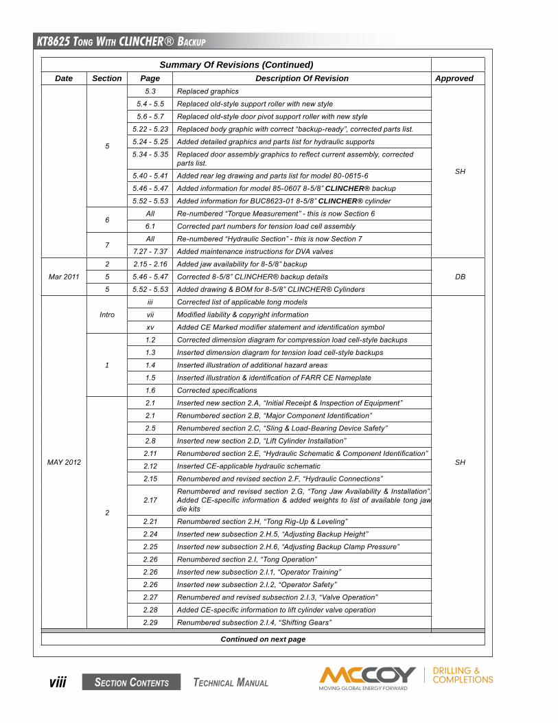
Summary Of Revisions (Continued)Date Section Page Description Of Revision Approved
5
5.3 Replacedgraphics
SH
5.4-5.5 Replacedold-stylesupportrollerwithnewstyle
5.6-5.7 Replacedold-styledoorpivotsupportrollerwithnewstyle
5.22-5.23 Replacedbodygraphicwithcorrect“backup-ready”,correctedpartslist.
5.24-5.25 Addeddetailedgraphicsandpartslistforhydraulicsupports
5.34-5.35 Replaceddoorassemblygraphicstoreflectcurrentassembly,correctedpartslist.
5.40-5.41 Addedrearlegdrawingandpartslistformodel80-0615-6
5.46-5.47 Addedinformationformodel85-06078-5/8”CLINCHER®backup5.52-5.53 AddedinformationforBUC8623-018-5/8”CLINCHER®cylinder
6All Re-numbered“TorqueMeasurement”-thisisnowSection6
6.1 Correctedpartnumbersfortensionloadcellassembly
7All Re-numbered“HydraulicSection”-thisisnowSection7
7.27-7.37 AddedmaintenanceinstructionsforDVAvalves
Mar2011
2 2.15-2.16 Addedjawavailabilityfor8-5/8”backup
DB5 5.46-5.47 Corrected8-5/8”CLINCHER®backupdetails
5 5.52-5.53 Addeddrawing&BOMfor8-5/8”CLINCHER®Cylinders
MAY2012
Intro
iii Correctedlistofapplicabletongmodels
SH
vii Modifiedliability©rightinformation
xv AddedCEMarkedmodifierstatementandidentificationsymbol
1
1.2 Correcteddimensiondiagramforcompressionloadcell-stylebackups
1.3 Inserteddimensiondiagramfortensionloadcell-stylebackups
1.4 Insertedillustrationofadditionalhazardareas
1.5 Insertedillustration&identificationofFARRCENameplate
1.6 Correctedspecifications
2
2.1 Insertednewsection2.A,“InitialReceipt&InspectionofEquipment”
2.1 Renumberedsection2.B,“MajorComponentIdentification”
2.5 Renumberedsection2.C,“Sling&Load-BearingDeviceSafety”
2.8 Insertednewsection2.D,“LiftCylinderInstallation”
2.11 Renumberedsection2.E,“HydraulicSchematic&ComponentIdentification”
2.12 InsertedCE-applicablehydraulicschematic
2.15 Renumberedandrevisedsection2.F,“HydraulicConnections”
2.17Renumberedandrevisedsection2.G,“TongJawAvailability& Installation”.AddedCE-specific information&addedweights to listofavailable tong jawdiekits
2.21 Renumberedsection2.H,“TongRig-Up&Leveling”
2.24 Insertednewsubsection2.H.5,“AdjustingBackupHeight”
2.25 Insertednewsubsection2.H.6,“AdjustingBackupClampPressure”
2.26 Renumberedsection2.I,“TongOperation”
2.26 Insertednewsubsection2.I.1,“OperatorTraining”
2.26 Insertednewsubsection2.I.2,“OperatorSafety”
2.27 Renumberedandrevisedsubsection2.I.3,“ValveOperation”
2.28 AddedCE-specificinformationtoliftcylindervalveoperation
2.29 Renumberedsubsection2.I.4,“ShiftingGears”
Continued on next page
KT8625 Tong WiTh CLinChER® BaCKup
Section contentS ix technical Manual
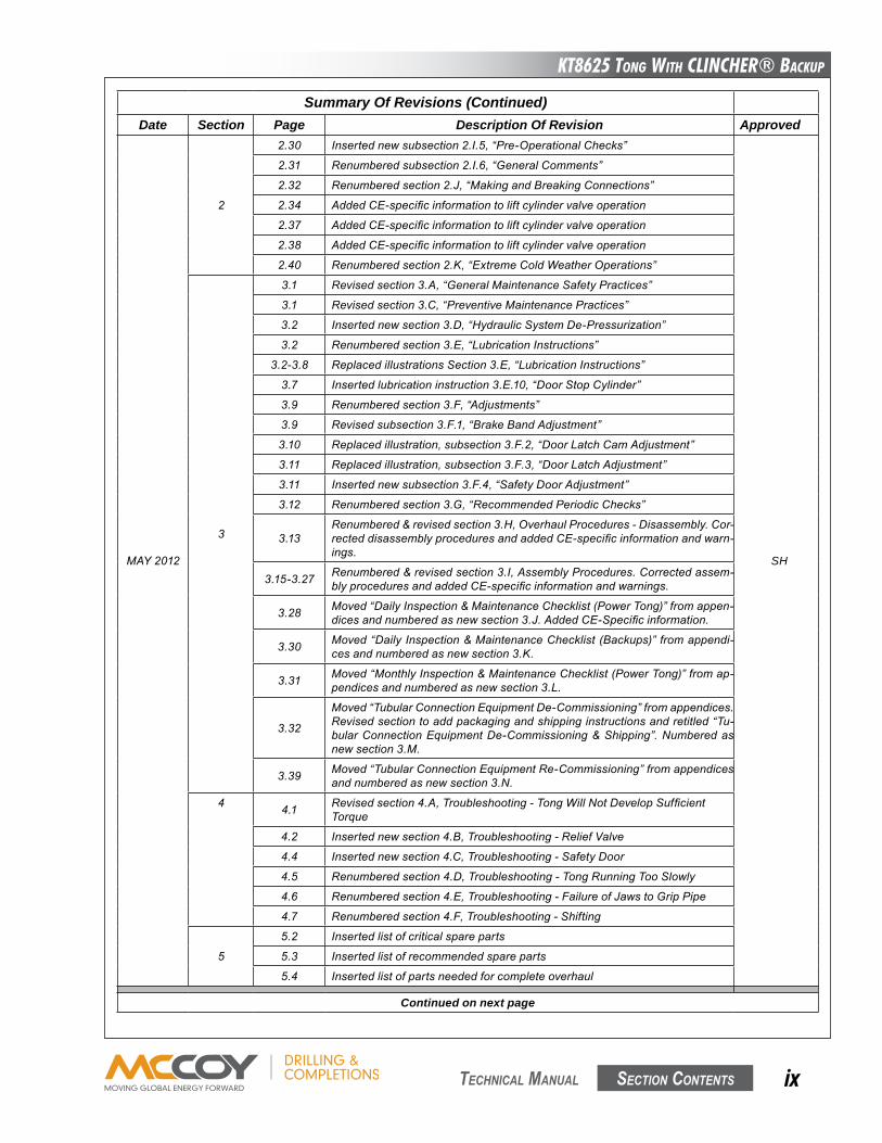
Summary Of Revisions (Continued)Date Section Page Description Of Revision Approved
MAY2012
2
2.30 Insertednewsubsection2.I.5,“Pre-OperationalChecks”
SH
2.31 Renumberedsubsection2.I.6,“GeneralComments”
2.32 Renumberedsection2.J,“MakingandBreakingConnections”
2.34 AddedCE-specificinformationtoliftcylindervalveoperation
2.37 AddedCE-specificinformationtoliftcylindervalveoperation
2.38 AddedCE-specificinformationtoliftcylindervalveoperation
2.40 Renumberedsection2.K,“ExtremeColdWeatherOperations”
3
3.1 Revisedsection3.A,“GeneralMaintenanceSafetyPractices”
3.1 Revisedsection3.C,“PreventiveMaintenancePractices”
3.2 Insertednewsection3.D,“HydraulicSystemDe-Pressurization”
3.2 Renumberedsection3.E,“LubricationInstructions”
3.2-3.8 ReplacedillustrationsSection3.E,“LubricationInstructions”
3.7 Insertedlubricationinstruction3.E.10,“DoorStopCylinder”
3.9 Renumberedsection3.F,“Adjustments”
3.9 Revisedsubsection3.F.1,“BrakeBandAdjustment”
3.10 Replacedillustration,subsection3.F.2,“DoorLatchCamAdjustment”
3.11 Replacedillustration,subsection3.F.3,“DoorLatchAdjustment”
3.11 Insertednewsubsection3.F.4,“SafetyDoorAdjustment”
3.12 Renumberedsection3.G,“RecommendedPeriodicChecks”
3.13Renumbered&revisedsection3.H,OverhaulProcedures-Disassembly.Cor-recteddisassemblyproceduresandaddedCE-specificinformationandwarn-ings.
3.15-3.27 Renumbered&revisedsection3.I,AssemblyProcedures.Correctedassem-blyproceduresandaddedCE-specificinformationandwarnings.
3.28 Moved“DailyInspection&MaintenanceChecklist(PowerTong)”fromappen-dicesandnumberedasnewsection3.J.AddedCE-Specificinformation.
3.30 Moved“DailyInspection&MaintenanceChecklist(Backups)”fromappendi-cesandnumberedasnewsection3.K.
3.31 Moved“MonthlyInspection&MaintenanceChecklist(PowerTong)”fromap-pendicesandnumberedasnewsection3.L.
3.32
Moved“TubularConnectionEquipmentDe-Commissioning”fromappendices.Revisedsectiontoaddpackagingandshippinginstructionsandretitled“Tu-bularConnectionEquipmentDe-Commissioning&Shipping”.Numberedasnewsection3.M.
3.39 Moved“TubularConnectionEquipmentRe-Commissioning”fromappendicesandnumberedasnewsection3.N.
4 4.1 Revisedsection4.A,Troubleshooting-TongWillNotDevelopSufficientTorque
4.2 Insertednewsection4.B,Troubleshooting-ReliefValve
4.4 Insertednewsection4.C,Troubleshooting-SafetyDoor
4.5 Renumberedsection4.D,Troubleshooting-TongRunningTooSlowly
4.6 Renumberedsection4.E,Troubleshooting-FailureofJawstoGripPipe
4.7 Renumberedsection4.F,Troubleshooting-Shifting
5
5.2 Insertedlistofcriticalspareparts
5.3 Insertedlistofrecommendedspareparts
5.4 Insertedlistofpartsneededforcompleteoverhaul
Continued on next page
KT8625 Tong WiTh CLinChER® BaCKup
Section contentSx technical Manual
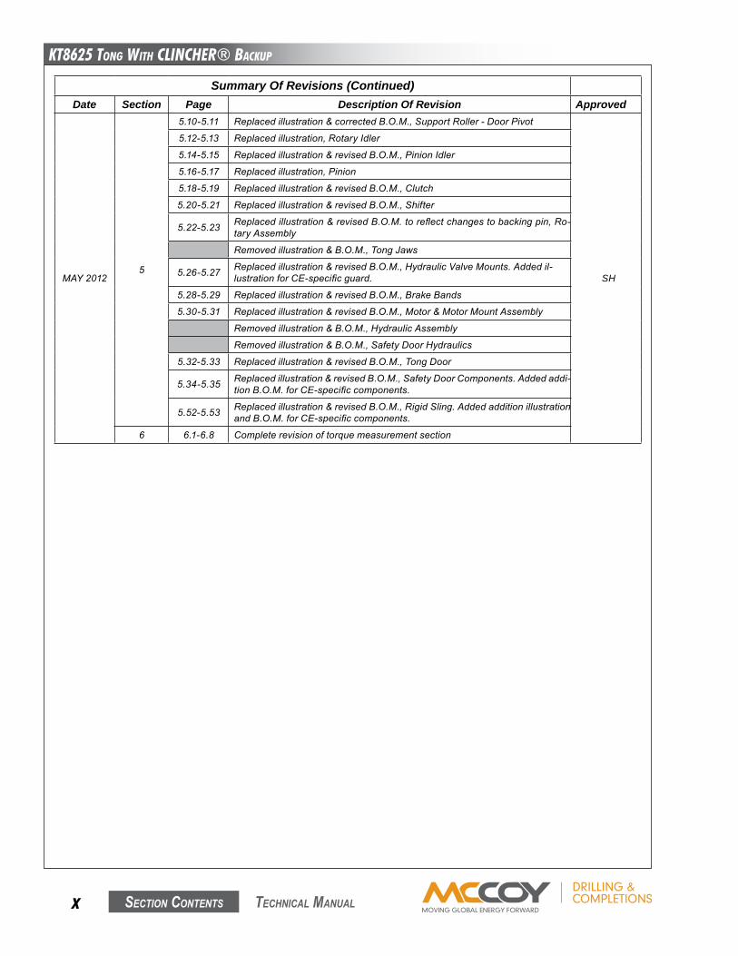
Summary Of Revisions (Continued)Date Section Page Description Of Revision Approved
MAY20125
5.10-5.11 Replacedillustration&correctedB.O.M.,SupportRoller-DoorPivot
SH
5.12-5.13 Replacedillustration,RotaryIdler
5.14-5.15 Replacedillustration&revisedB.O.M.,PinionIdler
5.16-5.17 Replacedillustration,Pinion
5.18-5.19 Replacedillustration&revisedB.O.M.,Clutch
5.20-5.21 Replacedillustration&revisedB.O.M.,Shifter
5.22-5.23 Replacedillustration&revisedB.O.M.toreflectchangestobackingpin,Ro-taryAssembly
Removedillustration&B.O.M.,TongJaws
5.26-5.27 Replacedillustration&revisedB.O.M.,HydraulicValveMounts.Addedil-lustrationforCE-specificguard.
5.28-5.29 Replacedillustration&revisedB.O.M.,BrakeBands
5.30-5.31 Replacedillustration&revisedB.O.M.,Motor&MotorMountAssembly
Removedillustration&B.O.M.,HydraulicAssembly
Removedillustration&B.O.M.,SafetyDoorHydraulics
5.32-5.33 Replacedillustration&revisedB.O.M.,TongDoor
5.34-5.35 Replacedillustration&revisedB.O.M.,SafetyDoorComponents.Addedaddi-tionB.O.M.forCE-specificcomponents.
5.52-5.53 Replacedillustration&revisedB.O.M.,RigidSling.AddedadditionillustrationandB.O.M.forCE-specificcomponents.
6 6.1-6.8 Completerevisionoftorquemeasurementsection
KT8625 Tong WiTh CLinChER® BaCKup
Section contentS xi technical Manual
taBleS of contentS
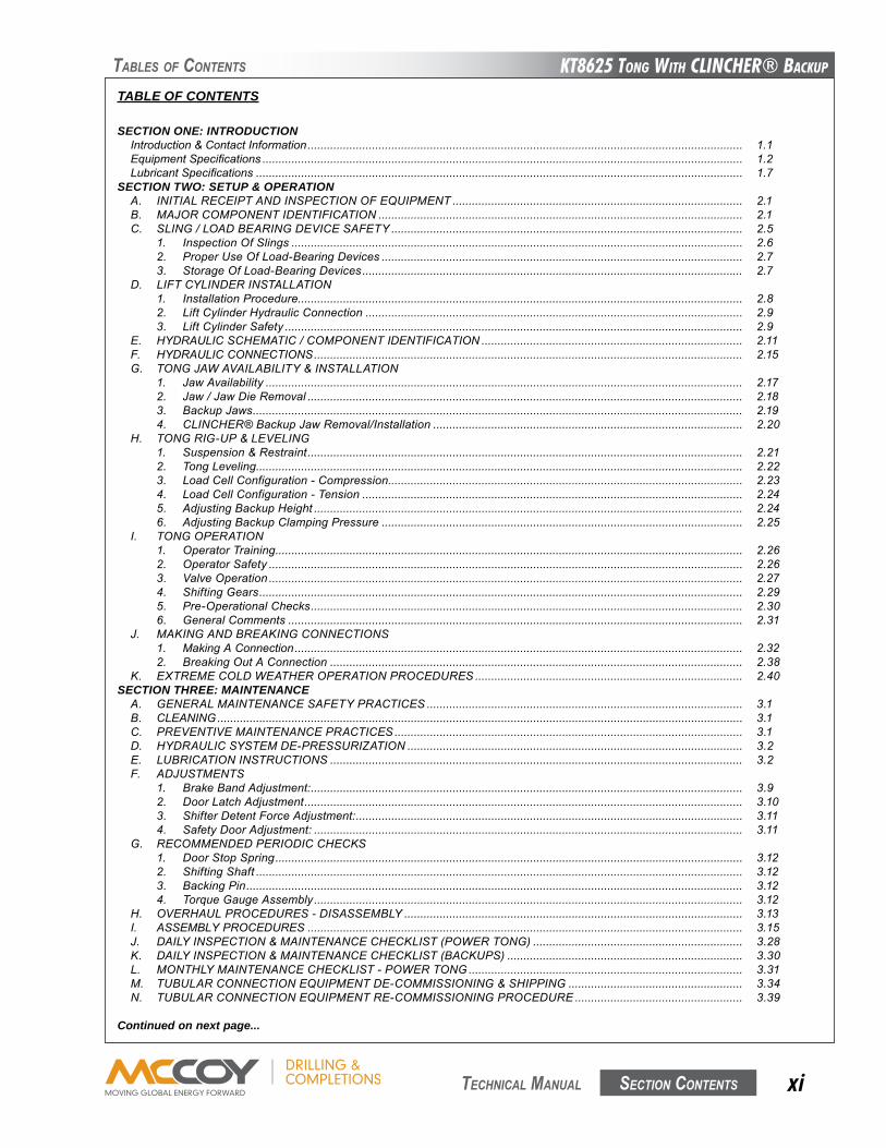
TABLE OF CONTENTS
SECTION ONE: INTRODUCTIONIntroduction&ContactInformation....................................................................................................................................... 1.1EquipmentSpecifications..................................................................................................................................................... 1.2LubricantSpecifications....................................................................................................................................................... 1.7
SECTION TWO: SETUP & OPERATIONA. INITIALRECEIPTANDINSPECTIONOFEqUIPMENT.......................................................................................... 2.1B. MAJORCOMPONENTIDENTIFICATION................................................................................................................. 2.1C. SLING/LOADBEARINGDEVICESAFETY............................................................................................................. 2.5
1. InspectionOfSlings............................................................................................................................................ 2.62. ProperUseOfLoad-BearingDevices................................................................................................................ 2.73. StorageOfLoad-BearingDevices...................................................................................................................... 2.7
D. LIFTCYLINDERINSTALLATION1. InstallationProcedure.......................................................................................................................................... 2.82. LiftCylinderHydraulicConnection..................................................................................................................... 2.93. LiftCylinderSafety.............................................................................................................................................. 2.9
E. HYDRAULICSCHEMATIC/COMPONENTIDENTIFICATION................................................................................. 2.11F. HYDRAULICCONNECTIONS..................................................................................................................................... 2.15G. TONGJAWAVAILABILITY&INSTALLATION
1. JawAvailability.................................................................................................................................................... 2.172. Jaw/JawDieRemoval....................................................................................................................................... 2.183. BackupJaws........................................................................................................................................................ 2.194. CLINCHER®BackupJawRemoval/Installation................................................................................................ 2.20
H. TONGRIG-UP&LEVELING1. Suspension&Restraint....................................................................................................................................... 2.212. TongLeveling....................................................................................................................................................... 2.223. LoadCellConfiguration-Compression.............................................................................................................. 2.234. LoadCellConfiguration-Tension...................................................................................................................... 2.245. AdjustingBackupHeight..................................................................................................................................... 2.246. AdjustingBackupClampingPressure................................................................................................................ 2.25
I. TONGOPERATION1. OperatorTraining................................................................................................................................................. 2.262. OperatorSafety................................................................................................................................................... 2.263. ValveOperation................................................................................................................................................... 2.274. ShiftingGears...................................................................................................................................................... 2.295. Pre-OperationalChecks...................................................................................................................................... 2.306. GeneralComments............................................................................................................................................. 2.31
J. MAKINGANDBREAKINGCONNECTIONS1. MakingAConnection........................................................................................................................................... 2.322. BreakingOutAConnection................................................................................................................................ 2.38
K. EXTREMECOLDWEATHEROPERATIONPROCEDURES................................................................................... 2.40SECTION THREE: MAINTENANCEA. GENERALMAINTENANCESAFETYPRACTICES.................................................................................................. 3.1B. CLEANING................................................................................................................................................................... 3.1C. PREVENTIVEMAINTENANCEPRACTICES............................................................................................................ 3.1D. HYDRAULICSYSTEMDE-PRESSURIzATION........................................................................................................ 3.2E. LUBRICATIONINSTRUCTIONS................................................................................................................................ 3.2F. ADJUSTMENTS
1. BrakeBandAdjustment:...................................................................................................................................... 3.92. DoorLatchAdjustment........................................................................................................................................ 3.103. ShifterDetentForceAdjustment:........................................................................................................................ 3.114. SafetyDoorAdjustment:..................................................................................................................................... 3.11
G. RECOMMENDEDPERIODICCHECKS1. DoorStopSpring................................................................................................................................................. 3.122. ShiftingShaft....................................................................................................................................................... 3.123. BackingPin.......................................................................................................................................................... 3.124. TorqueGaugeAssembly..................................................................................................................................... 3.12
H. OVERHAULPROCEDURES-DISASSEMBLY......................................................................................................... 3.13I. ASSEMBLYPROCEDURES....................................................................................................................................... 3.15J. DAILYINSPECTION&MAINTENANCECHECKLIST(POWERTONG)................................................................. 3.28K. DAILYINSPECTION&MAINTENANCECHECKLIST(BACKUPS)......................................................................... 3.30L. MONTHLYMAINTENANCECHECKLIST-POWERTONG..................................................................................... 3.31M. TUBULARCONNECTIONEqUIPMENTDE-COMMISSIONING&SHIPPING...................................................... 3.34N. TUBULARCONNECTIONEqUIPMENTRE-COMMISSIONINGPROCEDURE.................................................... 3.39
Continued on next page...

KT8625 Tong WiTh CLinChER® BaCKup
Section contentSxii technical Manual
TABLE OF CONTENTS (Continued)
SECTION FOUR: TROUBLESHOOTINGA. TONGWILLNOTDEVELOPSUFFICIENTTORqUE.............................................................................................. 4.1B. RELIEFVALVEISINCORRECTLYSETORNOTFUNCTIONING.......................................................................... 4.2C. SAFETYDOORDOESNOTOPERATEORISMALFUNCTIONING....................................................................... 4.4D. TONGRUNNINGTOOSLOWLY................................................................................................................................ 4.5E. FAILUREOFJAWSTOGRIPPIPE........................................................................................................................... 4.6F. FAILUREORDIFFICULTYOFTONGTOSHIFT..................................................................................................... 4.7G. GENERALCOMMENTS.............................................................................................................................................. 4.8
SECTION FIVE: ASSEMBLIES & PARTSCriticalSparePartsList.................................................................................................................................................... 5.2RecommendedSparePartsList...................................................................................................................................... 5.3PartsList-CompleteOverhaul........................................................................................................................................ 5.4GearTrainLayout............................................................................................................................................................ 5.6SupportRoller.................................................................................................................................................................. 5.8SupportRoller-DoorPivot.............................................................................................................................................. 5.10RotaryIdler....................................................................................................................................................................... 5.12PinionIdler...................................................................................................................................................................... 5.14PinionAssembly............................................................................................................................................................... 5.16ClutchAssembly............................................................................................................................................................... 5.18ShifterAssembly.............................................................................................................................................................. 5.20Rotary(CagePlate)Assembly......................................................................................................................................... 5.22TongBodyAssembly....................................................................................................................................................... 5.24HydraulicValve&LineSupports..................................................................................................................................... 5.26BrakeBandAssembly...................................................................................................................................................... 5.28Motor&MotorMountAssembly....................................................................................................................................... 5.30TongDoorAssembly........................................................................................................................................................ 5.32SafetyDoorAssembly...................................................................................................................................................... 5.34TongLegAssemblies(Model80-0615)........................................................................................................................... 5.36TongLegAssemblies(Model80-0615-6)........................................................................................................................ 5.38TongLegAssemblies(Model80-0615-4)........................................................................................................................ 5.40BackupBodyAssembly-CompressionStyle(Model80-0615)...................................................................................... 5.42BackupBodyAssembly-CompressionStyle(Model80-0615-6)................................................................................... 5.44BackupBodyAssembly-TensionStyle(Model80-0615-4)........................................................................................... 5.467-5/8”CLINCHER®BackupCylinders............................................................................................................................ 5.488-5/8”CLINCHER®BackupCylinders............................................................................................................................ 5.50RigidSlingAssembly....................................................................................................................................................... 5.52
SECTION SIX: TORQUE MEASUREMENTA. BASICTORqUEMEASUREMENT........................................................................................................................... 6.1B. TROUBLESHOOTING................................................................................................................................................. 6.6C. PERIODICINSPECTIONANDMAINTENANCE......................................................................................................... 6.7
1. Inspection............................................................................................................................................................ 6.72. FluidRecharge.................................................................................................................................................... 6.73. ReferenceCheckingYourTorqueMeasurementSystem.................................................................................. 6.74. RepairAndCalibration........................................................................................................................................ 6.8
SECTION SEVEN: HYDRAULIC COMPONENT INFORMATION
taBleS of contentS
KT8625 Tong WiTh CLinChER® BaCKup
Section contentS xiii technical Manual
taBleS of contentS
LIST OF ILLUSTRATIONSIllustratIon 1.a.1: Model 80-0615-Ce Kt8625 Ce-MarKed tong & CoMpressIon-style ClInCHer® BaCKup ....................... 1.1IllustratIon 1.a.2: Kt8625 tong & ClInCHer® BaCKup dIMensIons (Model 80-0615 sHown) ............................................... 1.2IllustratIon 1.a.3: Kt8625 tong & ClInCHer® BaCKup dIMensIons (Model 80-0615-4 sHown) ............................................ 1.3IllustratIon 1.a.4: Kt8625 tong & ClInCHer® BaCKup Hazard areas (Ce-MarKed asseMBly) ............................................. 1.4IllustratIon 1.a.5: Farr® Ce naMeplate ................................................................................................................................ 1.5IllustratIon 2.B.1: CoMponent IdentIFICatIon 01 ........................................................................................................................ 2.1IllustratIon 2.B.2: CoMponent IdentIFICatIon 02 ........................................................................................................................ 2.2IllustratIon 2.B.3: CoMponent IdentIFICatIon 03 ........................................................................................................................ 2.3IllustratIon 2.B.4: CoMponent IdentIFICatIon 04 ........................................................................................................................ 2.3IllustratIon 2.B.5: CoMponent IdentIFICatIon 05 ........................................................................................................................ 2.4IllustratIon 2.B.6: CoMponent IdentIFICatIon 06 ........................................................................................................................ 2.4IllustratIon 2.C.1: slIng angle ................................................................................................................................................. 2.5IllustratIon 2.d.1: lIFt CylInder & sprIng Hanger InstallatIon ................................................................................................ 2.8IllustratIon 2.d.2: lIFt CylInder HydraulIC ConneCtIon ............................................................................................................ 2.9IllustratIon 2.e.1: HydraulIC sCHeMatIC .................................................................................................................................... 2.11IllustratIon 2.e.2: HydraulIC sCHeMatIC - Ce MarKed .............................................................................................................. 2.12IllustratIon 2.e.3: HydraulIC CoMponent Id 01 ........................................................................................................................ 2.13IllustratIon 2.e.4: HydraulIC CoMponent Id 02 ........................................................................................................................ 2.13IllustratIon 2.e.5: HydraulIC CoMponent Id 03 ........................................................................................................................ 2.14IllustratIon 2.e.6: HydraulIC CoMponent Id 04 ........................................................................................................................ 2.14IllustratIon 2.e.7: HydraulIC CoMponent Id 05 ........................................................................................................................ 2.15IllustratIon 2.F.1: HydraulIC ConneCtIons 01 ........................................................................................................................... 2.15IllustratIon 2.F.2: HydraulIC ConneCtIons 02 ........................................................................................................................... 2.16IllustratIon 2.g.1: Jaw reMoval ............................................................................................................................................... 2.18IllustratIon 2.g.2: BaCKup Jaw extensIon ................................................................................................................................. 2.20IllustratIon 2.g.3: BaCKup Jaw dIe reMoval ............................................................................................................................. 2.20IllustratIon 2.g.4: BaCKup rear Jaw reMoval .......................................................................................................................... 2.21IllustratIon 2.H.1: tong levelIng - lateral adJustMent ........................................................................................................... 2.22IllustratIon 2.H.2: tong levelIng - axIal adJustMent ............................................................................................................... 2.23IllustratIon 2.H.3: CoMpressIon load Cell ConFIguratIon - MaKe up ....................................................................................... 2.23IllustratIon 2.H.4: CoMpressIon load Cell ConFIguratIon - BreaK out .................................................................................... 2.24IllustratIon 2.H.5: tensIon load Cell ConFIguratIon - MaKe up ............................................................................................... 2.24IllustratIon 2.I.1: HydraulIC Control - rotatIon ...................................................................................................................... 2.27IllustratIon 2.I.2: HydraulIC Control - lIFt CylInder ................................................................................................................ 2.28IllustratIon 2.I.3: HydraulIC Control - BaCKup ......................................................................................................................... 2.29IllustratIon 2.I.4: tong Manual sHIFter .................................................................................................................................... 2.30IllustratIon 2.J.1: rIgId slIng Master lInK ............................................................................................................................... 2.32IllustratIon 2.J.2: settIng BaCKIng pIn to “MaKe-up” posItIon .................................................................................................. 2.33IllustratIon 2.J.3: openIng tong door ..................................................................................................................................... 2.33IllustratIon 2.J.4: lIFt CylInder Control - raIse ...................................................................................................................... 2.34IllustratIon 2.J.5: BaCKup Control - ClaMp .............................................................................................................................. 2.35IllustratIon 2.J.6: Motor Control - MaKe-up ............................................................................................................................ 2.35IllustratIon 2.J.7: usIng Motor Control to release Jaws In “MaKe up” Mode ........................................................................ 2.36IllustratIon 2.J.8: usIng BaCKup Control to release BaCKup Jaws ......................................................................................... 2.37IllustratIon 2.J.9: usIng lIFt CylInder Control to lower asseMBly ........................................................................................ 2.37IllustratIon 2.J.10: settIng BaCKIng pIn to BreaK-out posItIon ............................................................................................... 2.38IllustratIon 2.J.11: Motor Control - BreaK out ....................................................................................................................... 2.39IllustratIon 2.J.12: usIng Motor Control to release Jaws In “BreaK out” Mode ................................................................... 2.40IllustratIon 3.e.1: CaM Follower luBrICatIon ........................................................................................................................... 3.2IllustratIon 3.e.2: support roller luBrICatIon ........................................................................................................................ 3.3IllustratIon 3.e.3: rotary Idler luBrICatIon ............................................................................................................................. 3.3IllustratIon 3.e.4: pInIon Idler luBrICatIon poInt ..................................................................................................................... 3.4IllustratIon 3.e.5: pInIon luBrICatIon poInts (top plate) ......................................................................................................... 3.4IllustratIon 3.e.6: pInIon luBrICatIon poInts (BottoM plate) .................................................................................................... 3.5IllustratIon 3.e.7: ClutCH luBrICatIon poInts ........................................................................................................................... 3.5IllustratIon 3.e.8: Motor Mount luBrICatIon poInt .................................................................................................................. 3.6IllustratIon 3.e.9: sHIFter sHaFt luBrICatIon ........................................................................................................................... 3.6IllustratIon 3.e.10: tong door luBrICatIon poInts .................................................................................................................. 3.7IllustratIon 3.e.11: door CylInder ........................................................................................................................................... 3.7IllustratIon 3.e.12: BaCKup ClaMp CylInder luBrICatIon poInts ............................................................................................... 3.8IllustratIon 3.e.13: CoMpressIon load Cell luBrICatIon........................................................................................................... 3.8
Continued on next page...
KT8625 Tong WiTh CLinChER® BaCKup
Section contentSxiv technical Manual
taBleS of contentS
LIST OF ILLUSTRATIONS (Continued)
IllustratIon 3.F.1: BraKe Band adJustMent ............................................................................................................................... 3.9IllustratIon 3.F.2: door latCH CaM adJustMent ....................................................................................................................... 3.10IllustratIon 3.F.3: sHIFter detent ForCe adJustMent ............................................................................................................... 3.11IllustratIon 3.F.4: saFety door swItCH adJustMent 01 ............................................................................................................ 3.12IllustratIon 3.I.1: tong asseMBly - rotary gear InstallatIon ................................................................................................... 3.16IllustratIon 3.I.2: tong asseMBly - gear asseMBly posItIonIng................................................................................................. 3.17IllustratIon 3.I.3: tong asseMBly - top Fastener loCatIons ..................................................................................................... 3.18IllustratIon 3.I.4: tong asseMBly - support rollers (leg Mount loCatIons) ........................................................................... 3.19IllustratIon 3.I.5: tong asseMBly - support rollers (seCurIng leg Mounts)........................................................................... 3.19IllustratIon 3.I.6: tong asseMBly - support rollers (BraKe Band weldMents) ........................................................................ 3.20IllustratIon 3.I.7: tong asseMBly - top sHIFter BusHIng asseMBly ........................................................................................... 3.21IllustratIon 3.I.8: tong asseMBly - Front Cage plate spaCers ................................................................................................ 3.22IllustratIon 3.I.9: tong asseMBly - saFety door valve InstallatIon ......................................................................................... 3.23IllustratIon 3.I.10: tong asseMBly - rIgId slIng adJustMent Bolt InstallatIon ......................................................................... 3.24IllustratIon 3.I.11: tong asseMBly - valve Handle guard InstallatIon - Ce MarKed ............................................................ 3.27IllustratIon 3.M.1: sHIppIng InstruCtIons - pallet .................................................................................................................... 3.36IllustratIon 3.M.2: sHIppIng InstruCtIons - wrappIng CHaIn slIng ............................................................................................. 3.37IllustratIon 3.M.3: sHIppIng InstruCtIons - BaCKup support ..................................................................................................... 3.37IllustratIon 3.M.4: sHIppIng InstruCtIons - strappIng equIpMent to pallet .............................................................................. 3.38IllustratIon 4.B.1: relIeF valve trouBlesHootIng - teMporary gauge InstallatIon ................................................................... 4.2IllustratIon 6.a.1: torque gauge (For IllustratIon purposes only) ........................................................................................ 6.1IllustratIon 6.a.2: tensIon load Cell ....................................................................................................................................... 6.1IllustratIon 6.a.3: CoMpressIon load Cell ............................................................................................................................... 6.1IllustratIon 6.a.4: tensIon load Cell exploded ....................................................................................................................... 6.3IllustratIon 6.a.5: CoMpressIon load Cell exploded ................................................................................................................ 6.4IllustratIon 6.a.5: turn Counter enCoder Mount .................................................................................................................... 6.5

KT8625 Tong WiTh CLinChER® BaCKup
Section contentS xv technical Manual
taBleS of contentS
IDENTIFICATION OF OF WARNINGS AND OTHER NOMENCLATURE OF IMPORTANCE USED IN THIS INSTALLATION GUIDE
McCoyDrilling&Completionsusesthreeindicatorstodescribeitemsofthreedegreesofimportance.
AHAZARDtooperatorsorequipmentisrepresentedbyanexclamationpointwithinaredtriangle.identifiesitemsofthehighestimportance.FailuretoheedinformationidentifiedbyaHAZARDsymbolmayresult inbodilyinjury,death,cata-strophicequipmentdamage,oranycombinationofthese.AHAZARDmayalsoindicatethepotentialfordangerousenvi-ronmentalcontamination.
The informationpresented in thisdocumentwill providesetup,operating,andmaintenance instructions foryourKT8625tongandbackup.Duetothewidevarietyofoperatingconditions,theseinstructionsmustbecon-sideredguidelinesratherthanabsoluteoperatingprocedures.Itistheresponsibilityoftheusertousetheseguidelinestogetherwithanexperiencedmanagertodevelopoperatingproceduresthatconformtoallpoliciessetforthbytheoperatingauthority(ies).
AWARNINGisrepresentedbyanexclamationpointwithinanorangetriangle,andcontainsinformationthatwillalertper-sonneltoapotentialsafetyhazardthatisnotlife-threatening.AWARNINGmayalsoservetoalerttheusertoinformationcriticaltothecorrectassemblyoroperationoftheequipmentinuse.
This identifies a HAZARD to operators or equipment
This identifies a WARNING to users
ACAUTIONisrepresentedbyanexclamationpointwithinayellowtriangleandhighlightsinformationthatmayaidtheuserduringassemblyoroperationofyourequipment.CAUTIONsarealsousedtoensurecommonerrorsarenotmadeduringassemblyoroperationofyourequipment.
This identifies a CAUTION to users
Observance of the following is the full responsibility of the user:
● all descriptions, information and instructions set out in this manual● any regulation or requirement issued by an authority or agency which may influence operation,
safety or integrity of the equipment that overrules the content of this document.● any legal or other mandatory regulation in force governing accident prevention or environmental
protection.
Somesectionsofthistechnicalmanualapplyonlyto“CE Marked”equipment.Thesesectionswillbeclearlyidentifiedbytheuseofthephrase“appliestoCE-markedtongsonly”,orbyuseoftheCElogowithinanenclosedborder.
This identifies a section that only applies to CE-Marked equipment

This page intentionallyleft blank
KT8625 Tong WiTh CLinChER® BaCKup
Section contentS 1.1 technical Manual
intRoDuction
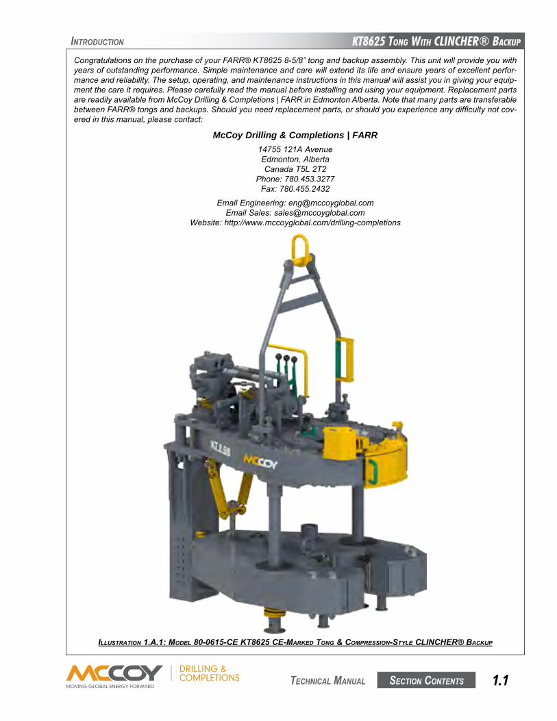
McCoy Drilling & Completions | FARR14755121AAvenueEdmonton,AlbertaCanadaT5L2T2
Phone:780.453.3277Fax:780.455.2432
EmailEngineering:[email protected]:[email protected]
Website:http://www.mccoyglobal.com/drilling-completions
ILLUSTRATION 1.A.1: MOdEL 80-0615-CE KT8625 CE-MARKEd TONg & COMpRESSION-STyLE CLINCHER® BACKUp
CongratulationsonthepurchaseofyourFARR®KT86258-5/8”tongandbackupassembly.Thisunitwillprovideyouwithyearsofoutstandingperformance.Simplemaintenanceandcarewillextenditslifeandensureyearsofexcellentperfor-manceandreliability.Thesetup,operating,andmaintenanceinstructionsinthismanualwillassistyouingivingyourequip-mentthecareitrequires.Pleasecarefullyreadthemanualbeforeinstallingandusingyourequipment.ReplacementpartsarereadilyavailablefromMcCoyDrilling&Completions|FARRinEdmontonAlberta.NotethatmanypartsaretransferablebetweenFARR®tongsandbackups.Shouldyouneedreplacementparts,orshouldyouexperienceanydifficultynotcov-eredinthismanual,pleasecontact:
KT8625 Tong WiTh CLinChER® BaCKup
Section contentS1.2 technical Manual
SPecificationS
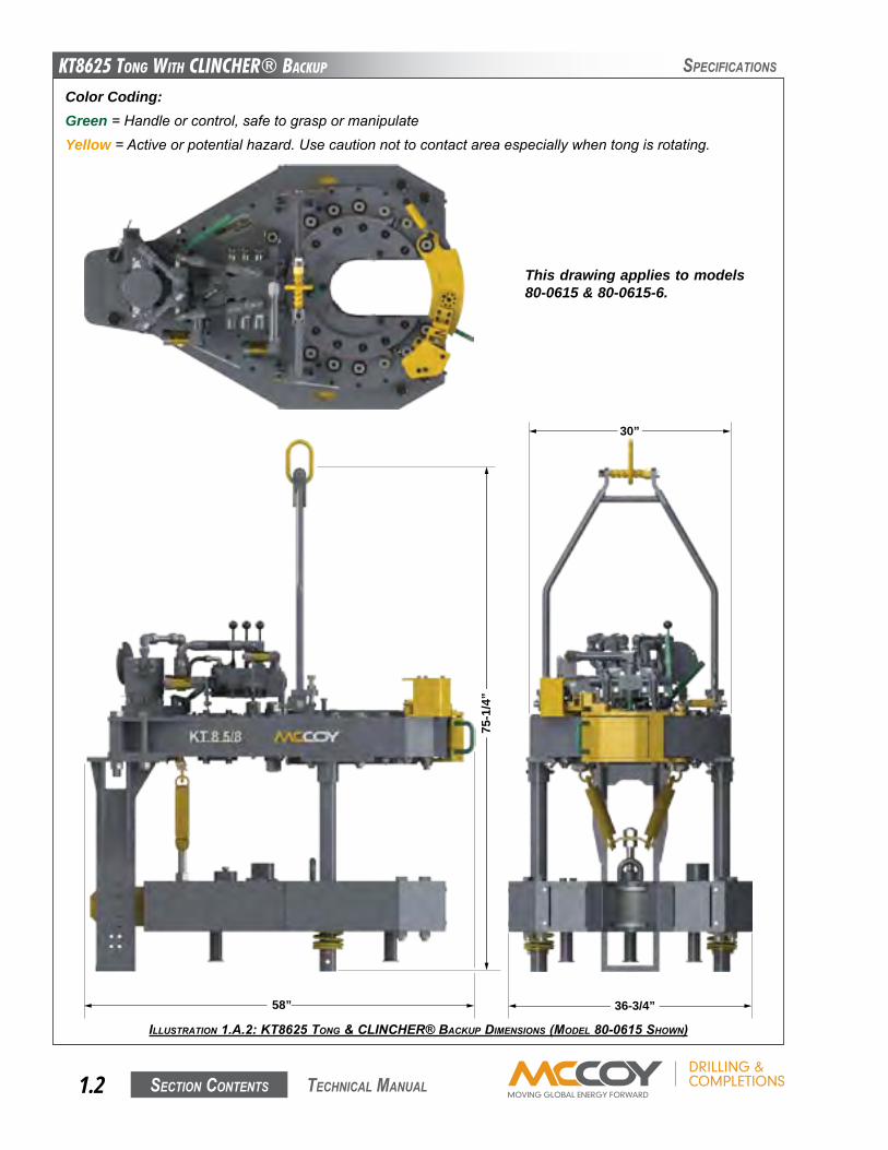
ILLUSTRATION 1.A.2: KT8625 TONg & CLINCHER® BACKUp dIMENSIONS (MOdEL 80-0615 SHOwN)
Color Coding:Green=Handleorcontrol,safetograspormanipulateYellow=Activeorpotentialhazard.Usecautionnottocontactareaespeciallywhentongisrotating.
58”
30”
36-3/4”
75-1
/4”
This drawing applies to models 80-0615 & 80-0615-6.
KT8625 Tong WiTh CLinChER® BaCKup
Section contentS 1.3 technical Manual
SPecificationS
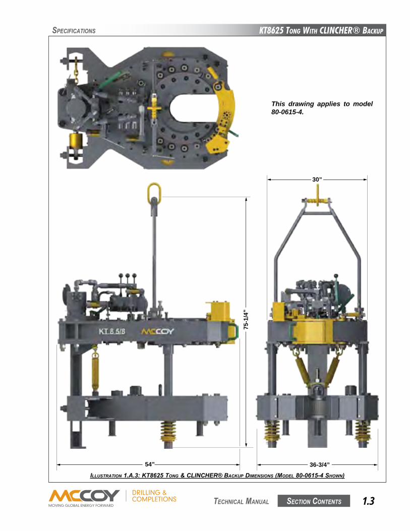
ILLUSTRATION 1.A.3: KT8625 TONg & CLINCHER® BACKUp dIMENSIONS (MOdEL 80-0615-4 SHOwN)
54”
30”
36-3/4”
75-1
/4”
This drawing applies to model 80-0615-4.
KT8625 Tong WiTh CLinChER® BaCKup
Section contentS1.4 technical Manual
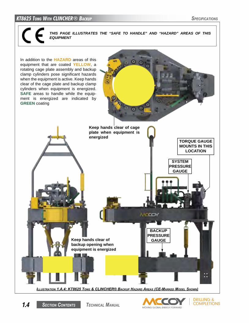
ILLUSTRATION 1.A.4: KT8625 TONg & CLINCHER® BACKUp HAzARd AREAS (CE-MARKEd MOdEL SHOwN)
SPecificationS
THIS PAGE ILLUSTRATES THE “SAFE TO HANDLE” AND “HAZARD” AREAS OF THIS EQUIPMENT
In addition to the HAZARD areas of this equipment that are coated YELLOW, a rotating cage plate assembly and backup clamp cylinders pose significant hazards when the equipment is active. Keep hands clear of the cage plate and backup clamp cylinders when equipment is energized. SAFE areas to handle while the equip-ment is energized are indicated by GREEN coating
Keep hands clear of cage plate when equipment is energized
Keep hands clear of backup opening when equipment is energized
TORQUE GAUGEMOUNTS IN THIS
LOCATION
SYSTEMPRESSURE
GAUGE
BACKUPPRESSURE
GAUGE

KT8625 Tong WiTh CLinChER® BaCKup
Section contentS 1.5 technical Manual
SPecificationS
ALL REPLACEMENT FASTENER (BOLTS, NUTS, CAP SCREWS, MACHINE SCREWS, ETC.) USED DURING MAINTENANCE OR OVERHAUL MUST BE GRADE 8 OR EQUIVALENT UNLESS OTHER-WISE SPECIFIED.
CEcompliant.ConformswiththeessentialrequirementsoftheapplicableConformitéEuropéennedirectives.
EUExplosiveAtmospherecertified
II EquipmentGroup(surface,non-mining)
2 EquipmentCategory-highlevelofprotection
Gc GasGroup(Acetylene&Hydrogen)-Certifiedforuseinacetyleneandhydrogenenvironments
T6 Maximumsurfacetemperatureof85oC.
ILLUSTRATION 1.A.5: FARR® CE NAMEpLATE
II 2 G c T6
KT8625 Tong WiTh CLinChER® BaCKup
Section contentS1.6 technical Manual
SPecificationS
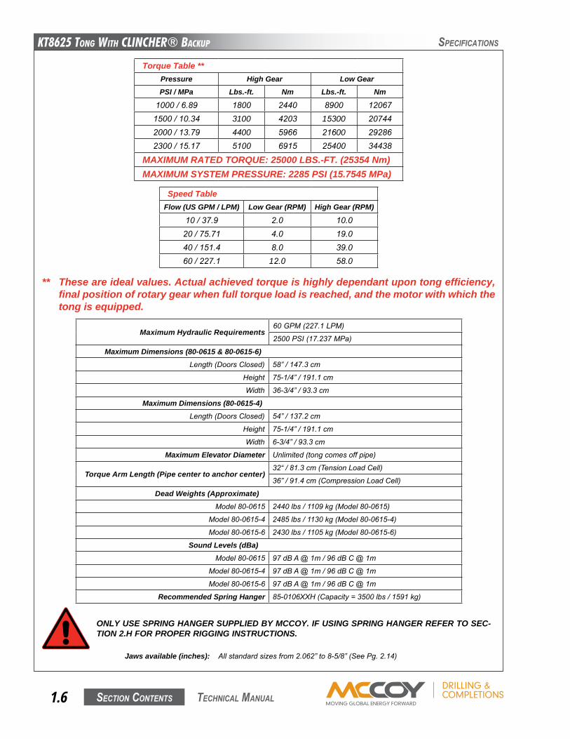
Torque Table **Pressure High Gear Low GearPSI / MPa Lbs.-ft. Nm Lbs.-ft. Nm
1000/6.89 1800 2440 8900 120671500/10.34 3100 4203 15300 207442000/13.79 4400 5966 21600 292862300/15.17 5100 6915 25400 34438
MAXIMUM RATED TORQUE: 25000 LBS.-FT. (25354 Nm)MAXIMUM SYSTEM PRESSURE: 2285 PSI (15.7545 MPa)
Speed TableFlow (US GPM / LPM) Low Gear (RPM) High Gear (RPM)
10/37.9 2.0 10.020/75.71 4.0 19.040/151.4 8.0 39.060/227.1 12.0 58.0
** These are ideal values. Actual achieved torque is highly dependant upon tong efficiency, final position of rotary gear when full torque load is reached, and the motor with which the tong is equipped.
Jaws available (inches): Allstandardsizesfrom2.062”to8-5/8”(SeePg.2.14)
ONLY USE SPRING HANGER SUPPLIED BY MCCOY. IF USING SPRING HANGER REFER TO SEC-TION 2.H FOR PROPER RIGGING INSTRUCTIONS.
Maximum Hydraulic Requirements60GPM(227.1LPM)
2500PSI(17.237MPa)
Maximum Dimensions (80-0615 & 80-0615-6)Length(DoorsClosed) 58”/147.3cm
Height 75-1/4”/191.1cm
Width 36-3/4”/93.3cm
Maximum Dimensions (80-0615-4)Length(DoorsClosed) 54”/137.2cm
Height 75-1/4”/191.1cm
Width 6-3/4”/93.3cm
Maximum Elevator Diameter Unlimited(tongcomesoffpipe)
Torque Arm Length (Pipe center to anchor center)32“/81.3cm(TensionLoadCell)
36”/91.4cm(CompressionLoadCell)
Dead Weights (Approximate)Model80-0615 2440lbs/1109kg(Model80-0615)
Model80-0615-4 2485lbs/1130kg(Model80-0615-4)
Model80-0615-6 2430lbs/1105kg(Model80-0615-6)
Sound Levels (dBa)Model80-0615 97dBA@1m/96dBC@1m
Model80-0615-4 97dBA@1m/96dBC@1m
Model80-0615-6 97dBA@1m/96dBC@1m
Recommended Spring Hanger 85-0106XXH(Capacity=3500lbs/1591kg)
KT8625 Tong WiTh CLinChER® BaCKup
Section contentS 1.7 technical Manual
SPecificationS
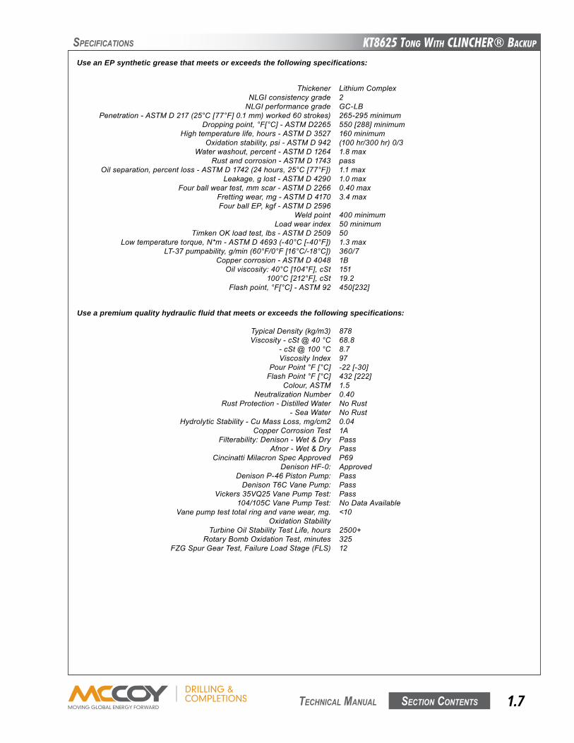
Use an EP synthetic grease that meets or exceeds the following specifications:
Thickener LithiumComplex NLGIconsistencygrade 2 NLGIperformancegrade GC-LB Penetration-ASTMD217(25°C[77°F]0.1mm)worked60strokes) 265-295minimum Droppingpoint,°F[°C]-ASTMD2265 550[288]minimum Hightemperaturelife,hours-ASTMD3527 160minimum Oxidationstability,psi-ASTMD942 (100hr/300hr)0/3 Waterwashout,percent-ASTMD1264 1.8max Rustandcorrosion-ASTMD1743 pass Oilseparation,percentloss-ASTMD1742(24hours,25°C[77°F]) 1.1max Leakage,glost-ASTMD4290 1.0max Fourballweartest,mmscar-ASTMD2266 0.40max Frettingwear,mg-ASTMD4170 3.4max FourballEP,kgf-ASTMD2596 Weldpoint 400minimum Loadwearindex 50minimum TimkenOKloadtest,lbs-ASTMD2509 50 Lowtemperaturetorque,N*m-ASTMD4693(-40°C[-40°F]) 1.3max LT-37pumpability,g/min(60°F/0°F[16°C/-18°C]) 360/7 Coppercorrosion-ASTMD4048 1B Oilviscosity:40°C[104°F],cSt 151 100°C[212°F],cSt 19.2 Flashpoint,°F[°C]-ASTM92 450[232]
Use a premium quality hydraulic fluid that meets or exceeds the following specifications: TypicalDensity(kg/m3) 878 Viscosity-cSt@40°C 68.8 -cSt@100°C 8.7 ViscosityIndex 97 PourPoint°F[°C] -22[-30] FlashPoint°F[°C] 432[222] Colour,ASTM 1.5 NeutralizationNumber 0.40 RustProtection-DistilledWater NoRust -SeaWater NoRust HydrolyticStability-CuMassLoss,mg/cm2 0.04 CopperCorrosionTest 1A Filterability:Denison-Wet&Dry Pass Afnor-Wet&Dry Pass CincinattiMilacronSpecApproved P69 DenisonHF-0: Approved DenisonP-46PistonPump: Pass DenisonT6CVanePump: Pass Vickers35Vq25VanePumpTest: Pass 104/105CVanePumpTest: NoDataAvailable Vanepumptesttotalringandvanewear,mg. <10 OxidationStability TurbineOilStabilityTestLife,hours 2500+ RotaryBombOxidationTest,minutes 325 FzGSpurGearTest,FailureLoadStage(FLS) 12

This page intentionallyleft blank
KT8625 Tong WiTh CLinChER® BaCKup
Section contentS 2.1 technical Manual
SetuP & oPeRation
YOUR EQUIPMENT HAS BEEN THOROUGHLY TESTED AND INSPECTED AT THE FACTORY. HOWEVER, MCCOY ADVISES INSPECTING YOUR EQUIPMENT FOR SHIPPING DAMAGE UPON RECEIPT AND TESTING YOUR TONG BEFORE RELEASING TO AN OPERATIONAL ENVIRONMENT.
Performavisual inspectionfollowingremovalofallpackagingmaterial. Immediately identifyanyshippingdamagetotheshippingcompany,andcorrectalldamagebeforeconnectingequipmenttoahydraulicpowersource.
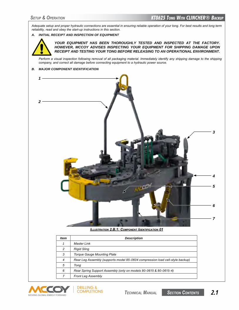
B. MAJOR COMPONENT IDENTIFICATION
Adequatesetupandproperhydraulicconnectionsareessentialinensuringreliableoperationofyourtong.Forbestresultsandlongtermreliability,readandobeythestart-upinstructionsinthissection.
A. INITIAL RECEIPT AND INSPECTION OF EQUIPMENT
Item Description1 MasterLink
2 RigidSling
3 TorqueGaugeMountingPlate
4 RearLegAssembly(supportsmodel85-0604compressionloadcell-stylebackup)
5 Tong
6 RearSpringSupportAssembly(onlyonmodels80-0615&80-0615-4)
7 FrontLegAssembly
ILLUSTRATION 2.B.1: COMpONENT IdENTIFICATION 01
7
5
4
1
2
3
6
KT8625 Tong WiTh CLinChER® BaCKup
Section contentS2.2 technical Manual
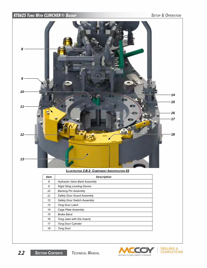
Item Description8 HydraulicValveBankAssembly
9 RigidSlingLevelingDevice
10 BackingPinAssembly
11 SafetyDoorGuardAssembly
12 SafetyDoorSwitchAssembly
13 TongDoorLatch
14 CagePlateAssembly
15 BrakeBand
16 TongJawswithDieInserts
17 TongDoorCylinder
18 TongDoor
ILLUSTRATION 2.B.2: COMpONENT IdENTIFICATION 02
SetuP & oPeRation
9
10
11
12
13
14
15
16
8
17
18
KT8625 Tong WiTh CLinChER® BaCKup
Section contentS 2.3 technical Manual
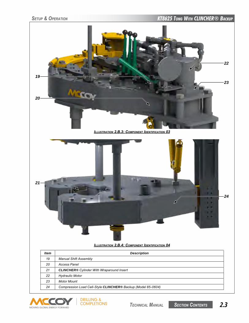
Item Description19 ManualShiftAssembly
20 AccessPanel
21 CLINCHER®CylinderWithWraparoundInsert
22 HydraulicMotor
23 MotorMount
24 CompressionLoadCell-StyleCLINCHER® Backup(Model85-0604)
ILLUSTRATION 2.B.4: COMpONENT IdENTIFICATION 04
ILLUSTRATION 2.B.3: COMpONENT IdENTIFICATION 03
SetuP & oPeRation
19
20
21
22
23
24
KT8625 Tong WiTh CLinChER® BaCKup
Section contentS2.4 technical Manual
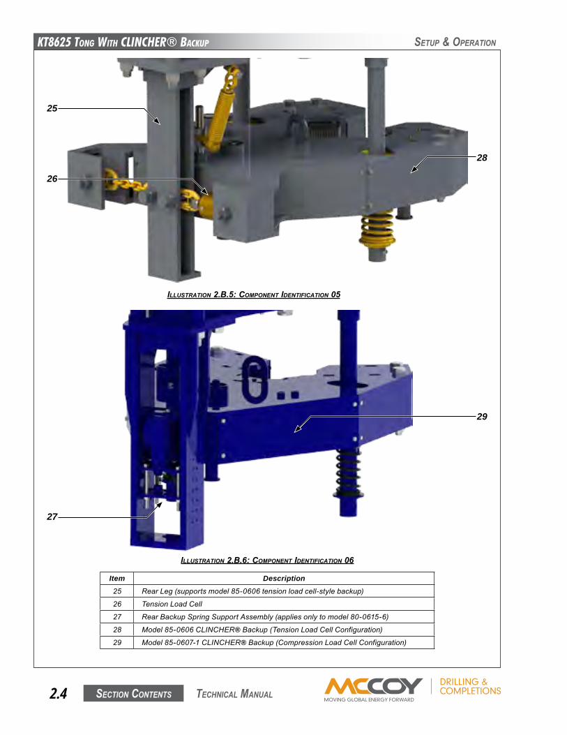
Item Description25 RearLeg(supportsmodel85-0606tensionloadcell-stylebackup)
26 TensionLoadCell
27 RearBackupSpringSupportAssembly(appliesonlytomodel80-0615-6)
28 Model85-0606CLINCHER®Backup(TensionLoadCellConfiguration)29 Model85-0607-1CLINCHER®Backup(CompressionLoadCellConfiguration)
ILLUSTRATION 2.B.6: COMpONENT IdENTIFICATION 06
ILLUSTRATION 2.B.5: COMpONENT IdENTIFICATION 05
SetuP & oPeRation
25
26
29
27
28
KT8625 Tong WiTh CLinChER® BaCKup
Section contentS 2.5 technical Manual
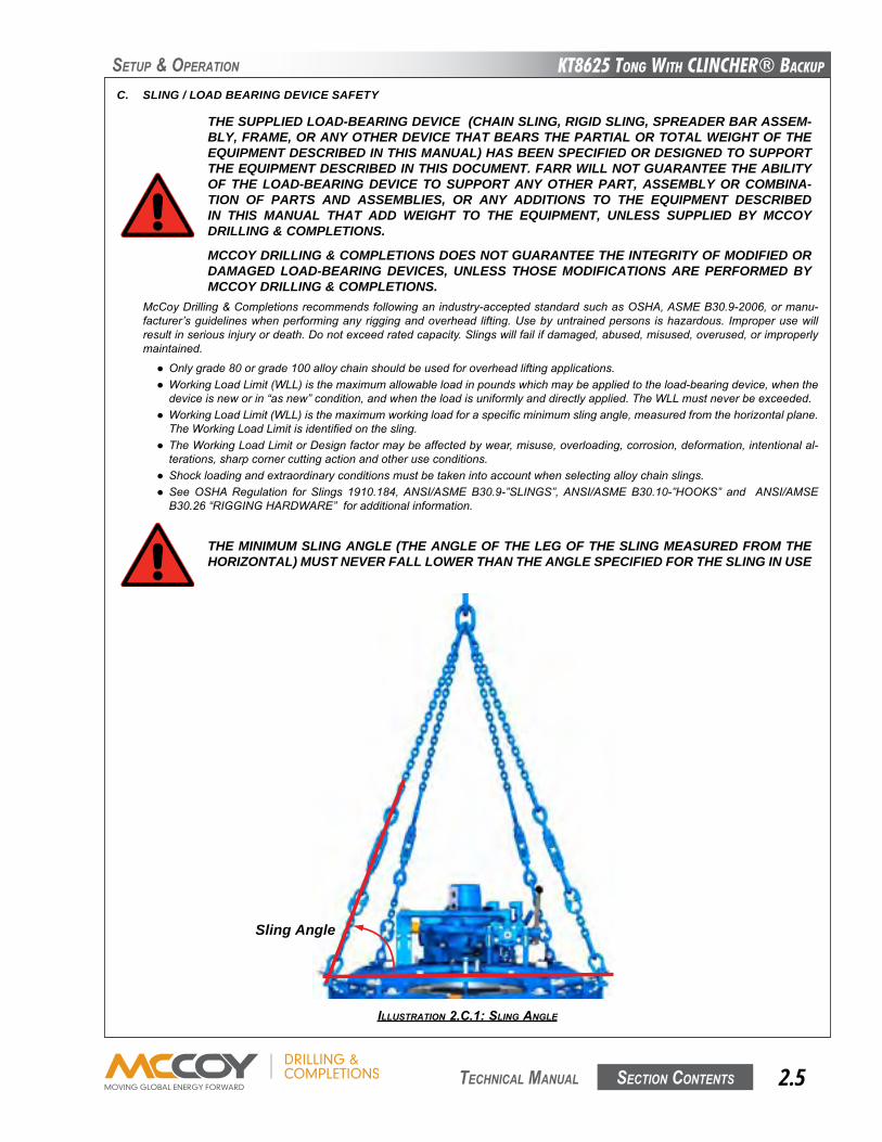
ILLUSTRATION 2.C.1: SLINg ANgLE
McCoyDrilling&Completionsrecommendsfollowinganindustry-acceptedstandardsuchasOSHA,ASMEB30.9-2006,ormanu-facturer’sguidelineswhenperforminganyriggingandoverhead lifting.Usebyuntrainedpersons ishazardous. Improperusewillresultinseriousinjuryordeath.Donotexceedratedcapacity.Slingswillfailifdamaged,abused,misused,overused,orimproperlymaintained.
● Onlygrade80orgrade100alloychainshouldbeusedforoverheadliftingapplications.● WorkingLoadLimit(WLL)isthemaximumallowableloadinpoundswhichmaybeappliedtotheload-bearingdevice,whenthedeviceisneworin“asnew”condition,andwhentheloadisuniformlyanddirectlyapplied.TheWLLmustneverbeexceeded.● WorkingLoadLimit(WLL)isthemaximumworkingloadforaspecificminimumslingangle,measuredfromthehorizontalplane.TheWorkingLoadLimitisidentifiedonthesling.● TheWorkingLoadLimitorDesignfactormaybeaffectedbywear,misuse,overloading,corrosion,deformation,intentionalal-terations,sharpcornercuttingactionandotheruseconditions.● Shockloadingandextraordinaryconditionsmustbetakenintoaccountwhenselectingalloychainslings.● SeeOSHARegulation for Slings 1910.184,ANSI/ASMEB30.9-”SLINGS”,ANSI/ASMEB30.10-”HOOKS” and ANSI/AMSEB30.26“RIGGINGHARDWARE”foradditionalinformation.
THE SUPPLIED LOAD-BEARING DEVICE (CHAIN SLING, RIGID SLING, SPREADER BAR ASSEM-BLY, FRAME, OR ANY OTHER DEVICE THAT BEARS THE PARTIAL OR TOTAL WEIGHT OF THE EQUIPMENT DESCRIBED IN THIS MANUAL) HAS BEEN SPECIFIED OR DESIGNED TO SUPPORT THE EQUIPMENT DESCRIBED IN THIS DOCUMENT. FARR WILL NOT GUARANTEE THE ABILITY OF THE LOAD-BEARING DEVICE TO SUPPORT ANY OTHER PART, ASSEMBLY OR COMBINA-TION OF PARTS AND ASSEMBLIES, OR ANY ADDITIONS TO THE EQUIPMENT DESCRIBED IN THIS MANUAL THAT ADD WEIGHT TO THE EQUIPMENT, UNLESS SUPPLIED BY MCCOY DRILLING & COMPLETIONS.
MCCOY DRILLING & COMPLETIONS DOES NOT GUARANTEE THE INTEGRITY OF MODIFIED OR DAMAGED LOAD-BEARING DEVICES, UNLESS THOSE MODIFICATIONS ARE PERFORMED BY MCCOY DRILLING & COMPLETIONS.
THE MINIMUM SLING ANGLE (THE ANGLE OF THE LEG OF THE SLING MEASURED FROM THE HORIZONTAL) MUST NEVER FALL LOWER THAN THE ANGLE SPECIFIED FOR THE SLING IN USE
C. SLING / LOAD BEARING DEVICE SAFETY
SetuP & oPeRation
Sling Angle

KT8625 Tong WiTh CLinChER® BaCKup
Section contentS2.6 technical Manual
SetuP & oPeRation
• Stretched,bent,twisted,ordeformedchainlinksorcomponents.• Evidenceofheatdamage.• Excessivepittingorcorrosion.• Lackofabilityofchainorcomponentstohinge(articulate)freely.• Weldsplatter.• Forhooks,removalcriteriaasstatedinASMEB30.10• Otherconditions,includingvisibledamage,thatcausedoubtastothecontinueduseofthesling.
Inspectall lugsand fixingpoints for signsof elongationand/orbending, or formaterial build-uparound thehole.Repair orreplacecomponents that appeardistorted.Ensureall hardware is tight and ingoodcondition.Replacemissinghardware ifnecessary.Allhardwaremustbefreeofrustandcorrosion.
Additionalinspectionsshallbeperformedduringslingusewhereserviceconditionswarrant.Periodicinspectionintervalsshallnotexceedoneyear.Thefrequencyofperiodicinspectionsshouldbebasedon:
• Frequencyofuseoftheload-bearingdevice.• Severityofserviceconditions• Natureofliftsbeingmade• Experiencegainedontheservicelifeofload-bearingdevicesusedinsimilarcircumstances.
Guidelinesfortheintervalare:
• NormalService-yearly• SevereService-monthlytoquarterly• SpecialService-asrecommendedbyaqualifiedperson
1. Inspection Of Slings
McCoy strongly recommends the following practices:Acompleteinspectionofnewload-bearingdevicesandattachmentsshallbeperformedbyaqualified,designatedpersonpriortoinitialuse.Eachlinkandcomponentshallbeexaminedindividually,takingcaretoexposeandexamineallsurfacesincludingtheinnerlinksurface.Theslingshallbeexaminedforconditionssuchasthoselistedintheremovalcriteriabelow.Inaddition,dailyinspectionofslings,fasteningsandattachmentsshallbeperformedbyadesignatedperson.Ifdamageordefectsarefoundateitherinspection,thedamagedordefectivecomponentshallbequarantinedfromserviceuntilitcanbeproperlyrepairedorreplaced.
RemovalCriteria:
Aload-bearingdeviceshallberemovedfromserviceifconditionssuchasthefollowingarepresent:
• Missingorillegibleslingidentification.• Cracksorbreaks• Evidenceoftamperingisseen-slingtaghasbeenmodifiedorobscured,ortamper-proofnutsaremissing.• Signsofimpactonload-bearingcomponents,includingspreaderbars,liftinglugs,rigidslings&rigidslingweldments,andlegs&legmounts.
• Brokenordamagedwelds.• Excessivewear,nicks,orgouges.Refertothechartbelowtoensureminimumthicknessonchainlinkssuppliedisnotbebelowthevalueslisted:
Minimum Allowable Chain Link Thickness at Any PointNominal Chain Size Minimum ThicknessInches MM Inches MM
7/32 5.5 0.189 4.80
9/32 7 0.239 6.07
5/16 8 0.273 6.93
3/8 10 0.342 8.69
1/2 13 0.443 11.26
5/8 16 0.546 13.87
3/4 20 0.687 17.45
7/8 22 0.750 19.05
1 26 0.887 22.53
1-1/4 32 1.091 27.71
Refer To ASME B30.9
KT8625 Tong WiTh CLinChER® BaCKup
Section contentS 2.7 technical Manual
SetuP & oPeRation
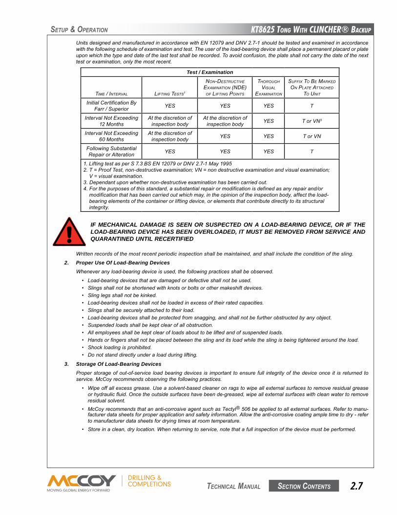
IF MECHANICAL DAMAGE IS SEEN OR SUSPECTED ON A LOAD-BEARING DEVICE, OR IF THE LOAD-BEARING DEVICE HAS BEEN OVERLOADED, IT MUST BE REMOVED FROM SERVICE AND QUARANTINED UNTIL RECERTIFIED
UnitsdesignedandmanufacturedinaccordancewithEN12079andDNV2.7-1shouldbetestedandexaminedinaccordancewiththefollowingscheduleofexaminationandtest.Theuseroftheload-bearingdeviceshallplaceapermanentplacardorplateuponwhichthetypeanddateofthelasttestshallberecorded.Toavoidconfusion,theplateshallnotcarrythedateofthenexttestorexamination,onlythemostrecent.
Test / Examination
tIMe / Interval lIFtIng tests1
non-destruCtIve exaMInatIon (nde)
oF lIFtIng poInts
tHorougH vIsual
exaMInatIon
suFFIx to Be MarKed on plate attaCHed
to unIt
InitialCertificationByFarr/Superior YES YES YES T
IntervalNotExceeding12Months
Atthediscretionofinspectionbody
Atthediscretionofinspectionbody YES TorVN3
IntervalNotExceeding60Months
Atthediscretionofinspectionbody YES YES TorVN
FollowingSubstantialRepairorAlteration YES YES YES T
1.LiftingtestasperS7.3BSEN12079orDNV2.7-1May19952.T=ProofTest,non-destructiveexamination;VN=nondestructiveexaminationandvisualexamination;V=visualexamination.3.Dependantuponwhethernon-destructiveexaminationhasbeencarriedout.4.Forthepurposesofthisstandard,asubstantialrepairormodificationisdefinedasanyrepairand/ormodificationthathasbeencarriedoutwhichmay,intheopinionoftheinspectionbody,affecttheload-bearingelementsofthecontainerorliftingdevice,orelementsthatcontributedirectlytoitsstructuralintegrity.
Writtenrecordsofthemostrecentperiodicinspectionshallbemaintained,andshallincludetheconditionofthesling.
2. Proper Use Of Load-Bearing DevicesWheneveranyload-bearingdeviceisused,thefollowingpracticesshallbeobserved.
• Load-bearingdevicesthataredamagedordefectiveshallnotbeused.• Slingsshallnotbeshortenedwithknotsorboltsorothermakeshiftdevices.• Slinglegsshallnotbekinked.• Load-bearingdevicesshallnotbeloadedinexcessoftheirratedcapacities.• Slingsshallbesecurelyattachedtotheirload.• Load-bearingdevicesshallbeprotectedfromsnagging,andshallnotbefurtherobstructedbyanyobject.• Suspendedloadsshallbekeptclearofallobstruction.• Allemployeesshallbekeptclearofloadsabouttobeliftedandofsuspendedloads.• Handsorfingersshallnotbeplacedbetweentheslinganditsloadwhiletheslingisbeingtightenedaroundtheload.• Shockloadingisprohibited.• Donotstanddirectlyunderaloadduringlifting.
3. Storage Of Load-Bearing DevicesProperstorageofout-of-service loadbearingdevices is important toensure full integrityof thedeviceonce it is returned toservice.McCoyrecommendsobservingthefollowingpractices.
• Wipeoffallexcessgrease.Useasolvent-basedcleaneronragstowipeallexternalsurfacestoremoveresidualgreaseorhydraulicfluid.Oncetheoutsidesurfaceshavebeende-greased,wipeallexternalsurfaceswithcleanwatertoremoveresidualsolvent.
• McCoyrecommendsthatananti-corrosiveagentsuchasTectyl®506beappliedtoallexternalsurfaces.Refertomanu-facturerdatasheetsforproperapplicationandsafetyinformation.Allowtheanti-corrosivecoatingampletimetodry-refertomanufacturerdatasheetsfordryingtimesatroomtemperature.
• Storeinaclean,drylocation.Whenreturningtoservice,notethatafullinspectionofthedevicemustbeperformed.
KT8625 Tong WiTh CLinChER® BaCKup
Section contentS2.8 technical Manual
SetuP & oPeRation
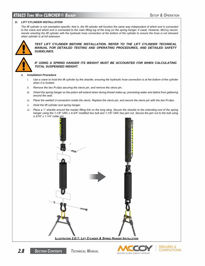
D. LIFT CYLINDER INSTALLATIONTheliftcylinderisnotorientation-specific;thatis,theliftcylinderwillfunctionthesamewayindependentofwhichendisconnectedtothecraneandwhichendisconnectedtothemainliftinglugofthetong(orthespringhanger,ifused).However,McCoyrecom-mendsorientingtheliftcylinderwiththehydraulichoseconnectionatthebottomofthecylindertoensurethehoseisnotstressedwhencylinderisatfullextension.
ILLUSTRATION 2.d.1: LIFT CyLINdER & SpRINg HANgER INSTALLATION
TEST LIFT CYLINDER BEFORE INSTALLATION. REFER TO THE LIFT CYLINDER TECHNICAL MANUAL FOR DETAILED TESTING AND OPERATING PROCEDURES, AND DETAILED SAFETY GUIDELINES.
1. Installation Procedurei. Useacranetohoisttheliftcylinderbytheshackle,ensuringthehydraulichoseconnectionisatthebottomofthecylinder
whenitishoisted.
ii. RemovethetwoR-clipssecuringtheclevispin,andremovetheclevispin.
iii. Orientthespringhangersothepistonwillextenddownduringthreadmake-up,preventingwateranddebrisfromgatheringaroundtheseal.
iv. PlacetheweldedU-connectioninsidetheclevis.Replacetheclevispin,andsecuretheclevispinwiththetwoR-clips.
v. Hoisttheliftcylinderandspringhanger.
vi. Placea1”shacklearoundthemasterliftinglinkonthetongsling.Securetheshackletotheextendingendofthespringhangerusingthe1-1/8”UNCx4-3/4”modifiedhexboltand1-1/8”UNChexjamnut.Securethejamnuttotheboltusinga3/16”x1-1/4”cotterpin.
IF USING A SPRING HANGER ITS WEIGHT MUST BE ACCOUNTED FOR WHEN CALCULATING TOTAL SUSPENDED WEIGHT.
KT8625 Tong WiTh CLinChER® BaCKup
Section contentS 2.9 technical Manual
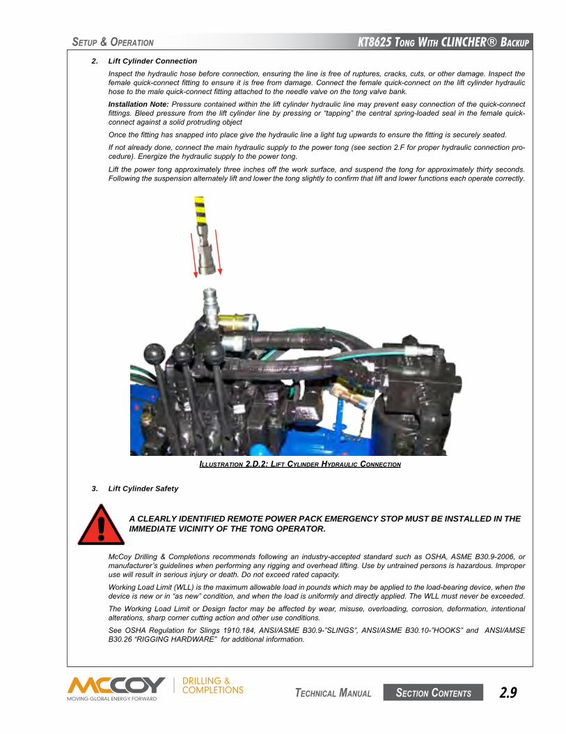
2. Lift Cylinder ConnectionInspectthehydraulichosebeforeconnection,ensuringthelineisfreeofruptures,cracks,cuts,orotherdamage.Inspectthefemalequick-connect fittingtoensure it is freefromdamage.Connect thefemalequick-connectonthe liftcylinderhydraulichosetothemalequick-connectfittingattachedtotheneedlevalveonthetongvalvebank.
Installation Note:Pressurecontainedwithintheliftcylinderhydrauliclinemaypreventeasyconnectionofthequick-connectfittings.Bleedpressure from the liftcylinder linebypressingor “tapping” thecentralspring-loadedseal in the femalequick-connectagainstasolidprotrudingobject
Oncethefittinghassnappedintoplacegivethehydrauliclinealighttugupwardstoensurethefittingissecurelyseated.
Ifnotalreadydone,connectthemainhydraulicsupplytothepowertong(seesection2.Fforproperhydraulicconnectionpro-cedure).Energizethehydraulicsupplytothepowertong.
Lift thepower tongapproximately three inchesoff theworksurface,andsuspend the tong forapproximately thirtyseconds.Followingthesuspensionalternatelyliftandlowerthetongslightlytoconfirmthatliftandlowerfunctionseachoperatecorrectly.
ILLUSTRATION 2.d.2: LIFT CyLINdER HydRAULIC CONNECTION
SetuP & oPeRation
3. Lift Cylinder Safety
A CLEARLY IDENTIFIED REMOTE POWER PACK EMERGENCY STOP MUST BE INSTALLED IN THE IMMEDIATE VICINITY OF THE TONG OPERATOR.
McCoyDrilling&Completions recommends following an industry-accepted standard suchasOSHA,ASMEB30.9-2006, ormanufacturer’sguidelineswhenperforminganyriggingandoverheadlifting.Usebyuntrainedpersonsishazardous.Improperusewillresultinseriousinjuryordeath.Donotexceedratedcapacity.
WorkingLoadLimit(WLL)isthemaximumallowableloadinpoundswhichmaybeappliedtotheload-bearingdevice,whenthedeviceisneworin“asnew”condition,andwhentheloadisuniformlyanddirectlyapplied.TheWLLmustneverbeexceeded.
TheWorkingLoadLimit orDesign factormaybeaffectedbywear,misuse, overloading, corrosion, deformation, intentionalalterations,sharpcornercuttingactionandotheruseconditions.
SeeOSHARegulation for Slings 1910.184,ANSI/ASMEB30.9-”SLINGS”,ANSI/ASMEB30.10-”HOOKS” and ANSI/AMSEB30.26“RIGGINGHARDWARE”foradditionalinformation.
KT8625 Tong WiTh CLinChER® BaCKup
Section contentS2.10 technical Manual
SetuP & oPeRation
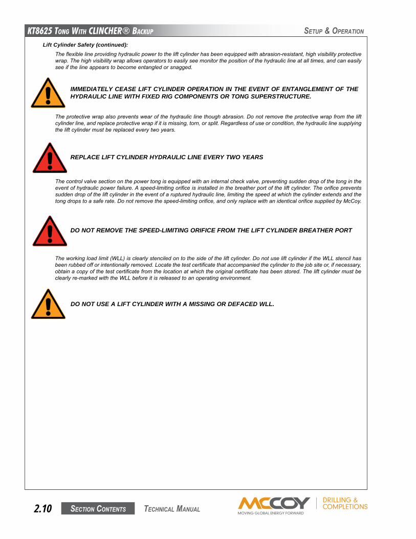
Lift Cylinder Safety (continued):Theflexiblelineprovidinghydraulicpowertotheliftcylinderhasbeenequippedwithabrasion-resistant,highvisibilityprotectivewrap.Thehighvisibilitywrapallowsoperatorstoeasilyseemonitorthepositionofthehydrauliclineatalltimes,andcaneasilyseeifthelineappearstobecomeentangledorsnagged.
IMMEDIATELY CEASE LIFT CYLINDER OPERATION IN THE EVENT OF ENTANGLEMENT OF THE HYDRAULIC LINE WITH FIXED RIG COMPONENTS OR TONG SUPERSTRUCTURE.
REPLACE LIFT CYLINDER HYDRAULIC LINE EVERY TWO YEARS
Theprotectivewrapalsopreventswearofthehydrauliclinethoughabrasion.Donotremovetheprotectivewrapfromtheliftcylinderline,andreplaceprotectivewrapifitismissing,torn,orsplit.Regardlessofuseorcondition,thehydrauliclinesupplyingtheliftcylindermustbereplacedeverytwoyears.
DO NOT REMOVE THE SPEED-LIMITING ORIFICE FROM THE LIFT CYLINDER BREATHER PORT
Thecontrolvalvesectiononthepowertongisequippedwithaninternalcheckvalve,preventingsuddendropofthetongintheeventofhydraulicpowerfailure.Aspeed-limitingorificeisinstalledinthebreatherportoftheliftcylinder.Theorificepreventssuddendropoftheliftcylinderintheeventofarupturedhydraulicline,limitingthespeedatwhichthecylinderextendsandthetongdropstoasaferate.Donotremovethespeed-limitingorifice,andonlyreplacewithanidenticalorificesuppliedbyMcCoy.
Theworkingloadlimit(WLL)isclearlystenciledontothesideoftheliftcylinder.DonotuseliftcylinderiftheWLLstencilhasbeenrubbedofforintentionallyremoved.Locatethetestcertificatethataccompaniedthecylindertothejobsiteor,ifnecessary,obtainacopyofthetestcertificatefromthelocationatwhichtheoriginalcertificatehasbeenstored.Theliftcylindermustbeclearlyre-markedwiththeWLLbeforeitisreleasedtoanoperatingenvironment.
DO NOT USE A LIFT CYLINDER WITH A MISSING OR DEFACED WLL.
KT8625 Tong WiTh CLinChER® BaCKup
Section contentS 2.11 technical Manual
SetuP & oPeRation
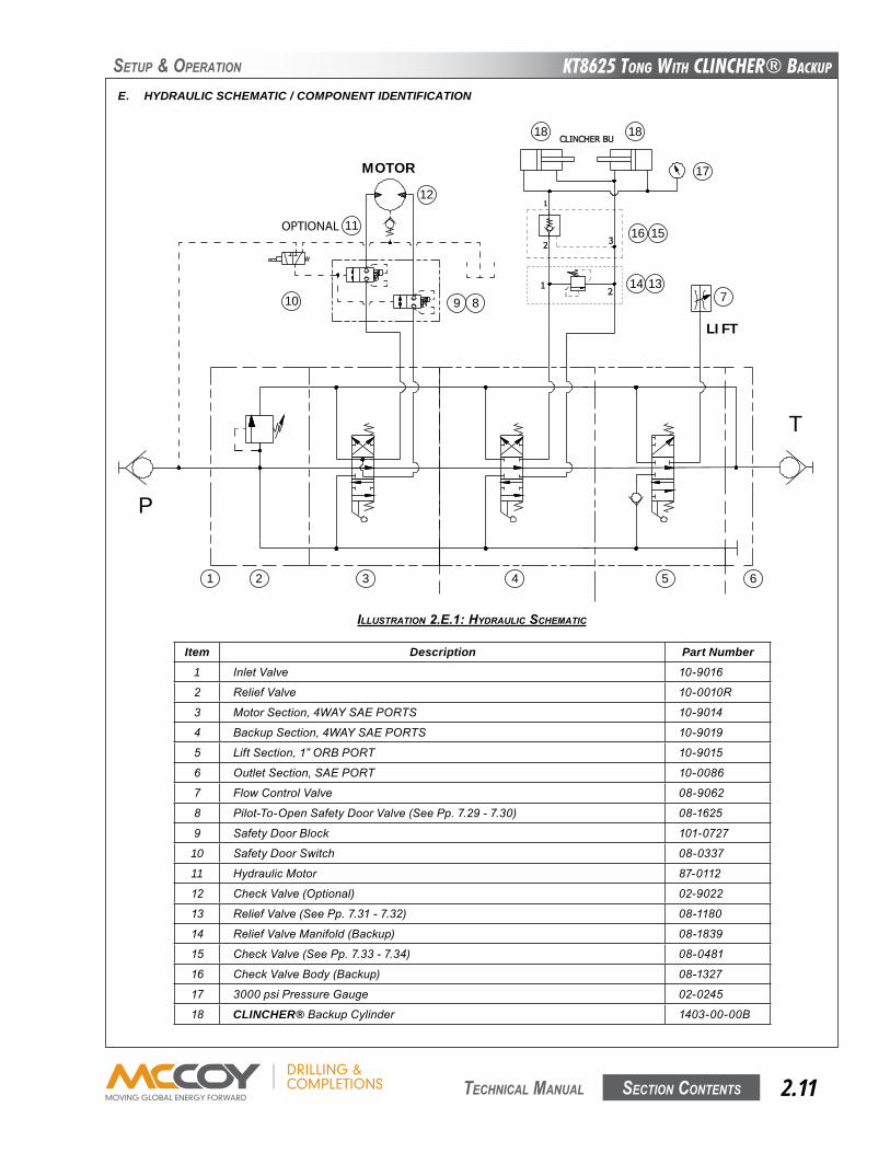
E. HYDRAULIC SCHEMATIC / COMPONENT IDENTIFICATION
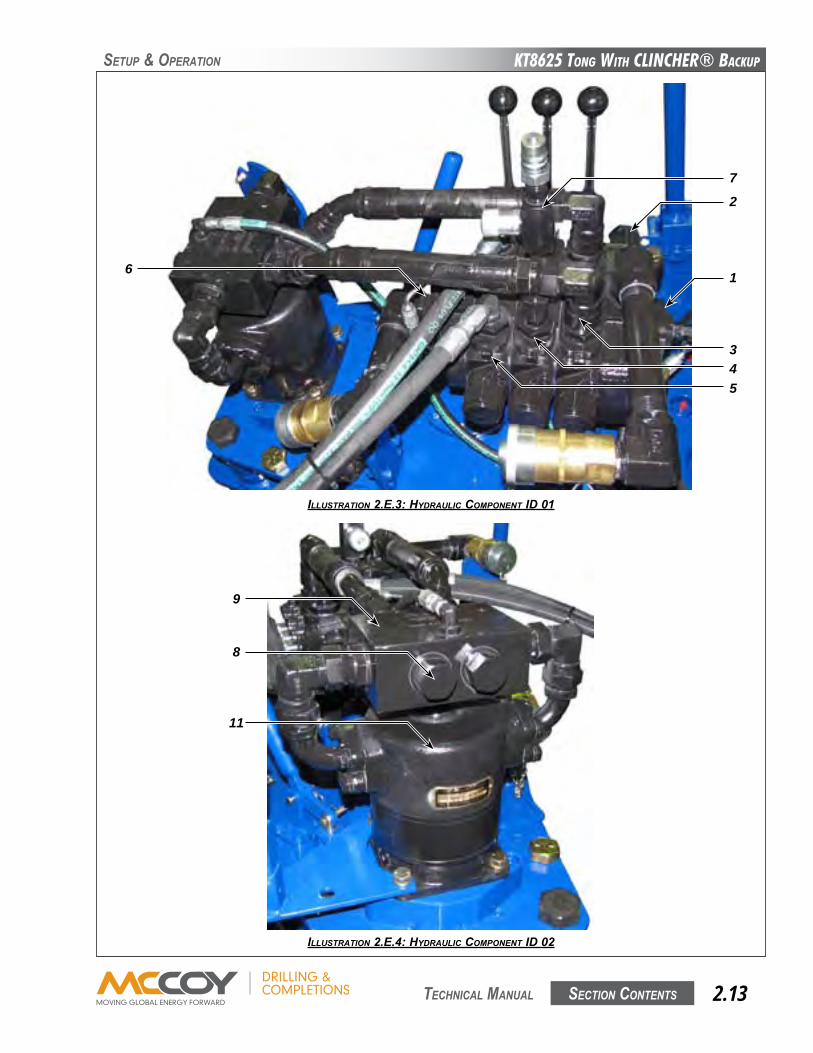
Item Description Part Number1 InletValve 10-9016
2 ReliefValve 10-0010R
3 MotorSection,4WAYSAEPORTS 10-9014
4 BackupSection,4WAYSAEPORTS 10-9019
5 LiftSection,1”ORBPORT 10-9015
6 OutletSection,SAEPORT 10-0086
7 FlowControlValve 08-9062
8 Pilot-To-OpenSafetyDoorValve(SeePp.7.29-7.30) 08-1625
9 SafetyDoorBlock 101-0727
10 SafetyDoorSwitch 08-0337
11 HydraulicMotor 87-0112
12 CheckValve(Optional) 02-9022
13 ReliefValve(SeePp.7.31-7.32) 08-1180
14 ReliefValveManifold(Backup) 08-1839
15 CheckValve(SeePp.7.33-7.34) 08-0481
16 CheckValveBody(Backup) 08-1327
17 3000psiPressureGauge 02-0245
18 CLINCHER®BackupCylinder 1403-00-00B
ILLUSTRATION 2.E.1: HydRAULIC SCHEMATIC
P
T
MOTOR
LIFT
14 13
16 15
17
18 18
1 2 3 4 5 6
12
11
9 810 7
OPTIONAL
KT8625 Tong WiTh CLinChER® BaCKup
Section contentS2.12 technical Manual
SetuP & oPeRation
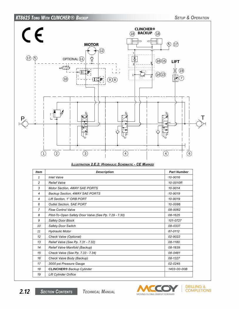
ILLUSTRATION 2.E.2: HydRAULIC SCHEMATIC - CE MARKEd
Item Description Part Number1 InletValve 10-9016
2 ReliefValve 10-0010R
3 MotorSection,4WAYSAEPORTS 10-9014
4 BackupSection,4WAYSAEPORTS 10-9019
4 LiftSection,1”ORBPORT 10-9019
6 OutletSection,SAEPORT 10-0086
7 FlowControlValve 08-9062
8 Pilot-To-OpenSafetyDoorValve(SeePp.7.29-7.30) 08-1625
9 SafetyDoorBlock 101-0727
10 SafetyDoorSwitch 08-0337
11 HydraulicMotor 87-0112
12 CheckValve(Optional) 02-9022
13 ReliefValve(SeePp.7.31-7.32) 08-1180
14 ReliefValveManifold(Backup) 08-1839
15 CheckValve(SeePp.7.33-7.34) 08-0481
16 CheckValveBody(Backup) 08-1327
17 3000psiPressureGauge 02-0245
18 CLINCHER®BackupCylinder 1403-00-00B
19 LiftCylinderOrifice
P T
14 13
16 15
17
18 18
1 2 3 4 4 6
12
11
9 810 7
OPTIONAL
19
MOTOR
CLINCHER®BACKUP
LIFT17
KT8625 Tong WiTh CLinChER® BaCKup
Section contentS 2.13 technical Manual
SetuP & oPeRation
ILLUSTRATION 2.E.3: HydRAULIC COMpONENT Id 01
ILLUSTRATION 2.E.4: HydRAULIC COMpONENT Id 02
6
7
543
1
2
9
8
11
KT8625 Tong WiTh CLinChER® BaCKup
Section contentS2.14 technical Manual
SetuP & oPeRation
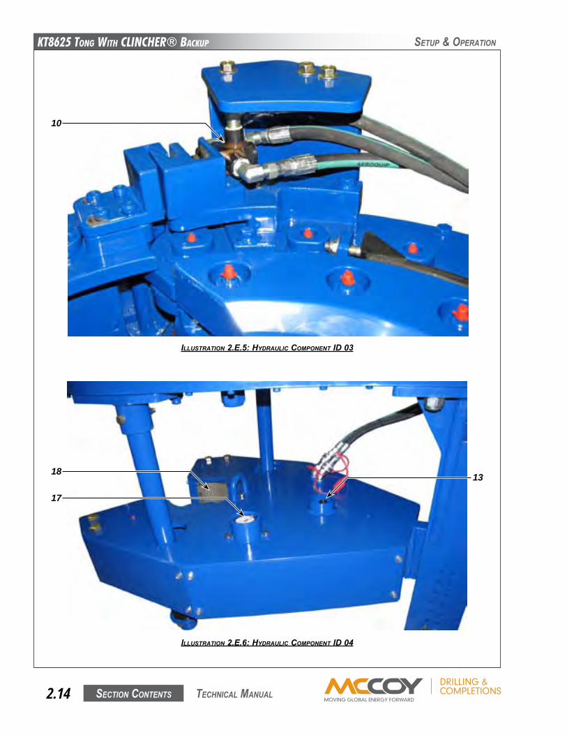
ILLUSTRATION 2.E.5: HydRAULIC COMpONENT Id 03
ILLUSTRATION 2.E.6: HydRAULIC COMpONENT Id 04
10
18 13
17
KT8625 Tong WiTh CLinChER® BaCKup
Section contentS 2.15 technical Manual
SetuP & oPeRation
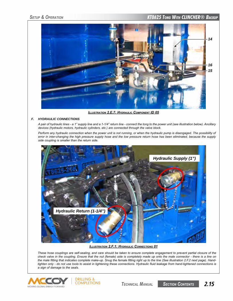
ILLUSTRATION 2.E.7: HydRAULIC COMpONENT Id 05
F. HYDRAULIC CONNECTIONSApairofhydrauliclines-a1”supplylineanda1-1/4”returnline-connectthetongtothepowerunit(seeillustrationbelow).Ancillarydevices(hydraulicmotors,hydrauliccylinders,etc.)areconnectedthroughthevalveblock.
Performanyhydraulicconnectionwhenthepowerunitisnotrunning,orwhenthehydraulicpumpisdisengaged.Thepossibilityoferrorininter-changingthehighpressuresupplyhoseandthelowpressurereturnhosehasbeeneliminated,becausethesupplysidecouplingissmallerthanthereturnside.
ILLUSTRATION 2.F.1: HydRAULIC CONNECTIONS 01
Thesehosecouplingsareself-sealing,andcareshouldbetakentoensurecompleteengagementtopreventpartialclosureofthecheckvalveinthecoupling.Ensurethatthenut(female)sideiscompletelymadeupontothemaleconnector-thereisalineonthemalefittingthatindicatescompletemake-up.Snugthefemalefittingrightuptotheline(Seeillustration2.F.2nextpage).Hand-tightenonly-donotusetoolstoassistintighteningtheseconnections.Hydraulicfluidleakagefromhand-tightenedconnectionsisasignofdamagetotheseals.
1615
14
Hydraulic Supply (1”)
Hydraulic Return (1-1/4”)
KT8625 Tong WiTh CLinChER® BaCKup
Section contentS2.16 technical Manual
SetuP & oPeRation
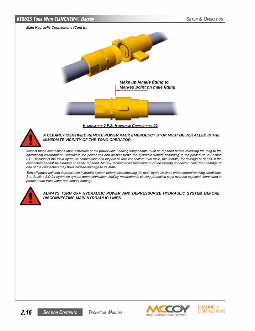
ILLUSTRATION 2.F.2: HydRAULIC CONNECTIONS 02
A CLEARLY IDENTIFIED REMOTE POWER PACK EMERGENCY STOP MUST BE INSTALLED IN THE IMMEDIATE VICINITY OF THE TONG OPERATOR.
Main Hydraulic Connections (Cont’d):
Inspecttheseconnectionsuponactivationofthepowerunit.Leakingcomponentsmustberepairedbeforereleasingthetongtotheoperationalenvironment.Deactivatethepowerunitandde-pressurizethehydraulicsystemaccordingtotheprocedureinSection3.D.Disconnectthemainhydraulicconnectionsandinspectallfourconnectors(twomale,twofemale)fordamageordebris.Iftheconnectorscannotbecleanedoreasilyrepaired,McCoyrecommendsreplacementoftheleakingconnector.Notethatdamagetooneoftheconnectorsmayhavecauseddamagetoitsmate.
Turnoffpowerunitanddepressurizehydraulicsystembeforedisconnectingthemainhydrauliclinesundernormalworkingconditions.SeeSection3.Dforhydraulicsystemdepressurization.McCoyrecommendsplacingprotectivecapsovertheexposedconnectorstoprotectthemfromwaterandimpactdamage.
ALWAYS TURN OFF HYDRAULIC POWER AND DEPRESSURIZE HYDRAULIC SYSTEM BEFORE DISCONNECTING MAIN HYDRAULIC LINES.
Make up female fitting to Marked point on male fitting
KT8625 Tong WiTh CLinChER® BaCKup
Section contentS 2.17 technical Manual
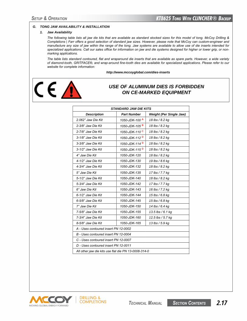
G. TONG JAW AVAILABILITY & INSTALLATION1. Jaw Availability
Thefollowingtable listsall jawdiekits thatareavailableasstandardstockedsizes for thismodelof tong.McCoyDrilling&Completions|Farroffersagoodselectionofstandardjawsizes.However,pleasenotethatMcCoycancustom-engineerandmanufactureanysizeof jawwithin therangeof the tong.Jawsystemsareavailable toallowuseofdie inserts intendedforspecializedapplications.Calloursalesofficeforinformationonjawanddiesystemsdesignedforhigherorlowergrip,ornon-markingapplications.
Thetablelistsstandardcontoured,flatandwraparounddieinsertsthatareavailableasspareparts.However,awidevarietyofdiamond-tooth,GRITFACE®,andwrap-aroundfine-toothdiesareavailableforspecializedapplications.Pleaserefertoourwebsiteforcompleteinformation:
http://www.mccoyglobal.com/dies-inserts
STANDARD JAW DIE KITSDescription Part Number Weight (Per Single Jaw)
2.062”JawDieKit 1050-JDK-100A 18lbs/8.2kg
2-3/8”JawDieKit 1050-JDK-105B 18lbs/8.2kg
2-7/8”JawDieKit 1050-JDK-110C 18lbs/8.2kg
3-1/8”JawDieKit 1050-JDK-112D 18lbs/8.2kg
3-3/8”JawDieKit 1050-JDK-114D 18lbs/8.2kg
3-1/2”JawDieKit 1050-JDK-115D 18lbs/8.2kg
4”JawDieKit 1050-JDK-120 18lbs/8.2kg
4-1/2”JawDieKit 1050-JDK-130 19lbs/8.6kg
4-3/4”JawDieKit 1050-JDK-132 18lbs/8.2kg
5”JawDieKit 1050-JDK-135 17lbs/7.7kg
5-1/2”JawDieKit 1050-JDK-140 18lbs/8.2kg
5-3/4”JawDieKit 1050-JDK-142 17lbs/7.7kg
6”JawDieKit 1050-JDK-143 16lbs/7.2kg
6-1/2”JawDieKit 1050-JDK-144 15lbs/6.8kg
6-5/8”JawDieKit 1050-JDK-145 15lbs/6.8kg
7”JawDieKit 1050-JDK-150 14lbs/6.4kg
7-5/8”JawDieKit 1050-JDK-155 13.5lbs/6.1kg
7-3/4”JawDieKit 1050-JDK-160 12.5lbs/5.7kg
8-5/8”JawDieKit 1050-JDK-165 13lbs/5.9kg
A-UsescontouredinsertPN12-0002
B-UsescontouredinsertPN12-0004
C-UsescontouredinsertPN12-0007
D-UsescontouredinsertPN12-0011
AllotherjawdiekitsuseflatdiePN13-0008-314-0
SetuP & oPeRation
USE OF ALUMINUM DIES IS FORBIDDEN ON CE-MARKED EQUIPMENT

KT8625 Tong WiTh CLinChER® BaCKup
Section contentS2.18 technical Manual
ILLUSTRATION 2.g.1: JAw REMOvAL
Oncethe jawhasbeenremoved,extract thediekeeperscrewsandremovethediesbytappingdies lightlywithahammer.Replacethedies,tappingthemintoplaceifnecessary,andreplacethekeeperscrews.
Tongjawsareclearlymarkedwiththesize.Ensurethejawtobeinstalledisthepropersizeforthepipetoberun.Over-sizedorunder-sizedjawsmayresultinjawslippage,orcausethejawstoleavetheendofthecamsurfaceontheinsideoftherotarygear.Additionally,incorrectlysizedjawswillcausethepipetobeoff-centrerelativetothebackup,resultingineccentricrotationandpotentialpipethreaddamage.
Useof jawsnotmanufacturedbyMcCoy isnot recommended,andmayresult in jawslippage jawfailure,ordamageto thecammingsurfacesoftherotarygear.
ENSURE JAWS TO BE INSTALLED ARE THE CORRECT SIZE. USE OF JAWS NOT SUPPLIED BY MCCOY MAY CAUSE JAW SLIPPAGE OR FAILURE, AND MAY RESULT IN DAMAGE TO THE TONG.THE USE OF REDUCER DIES IS NOT RECOMMENDED.
SetuP & oPeRation
DO NOT ACCESS ROTATING COMPONENTS UNLESS HYDRAULIC POWER SUPPLY HAS BEEN DEACTIVATED OR ISOLATED.
2. Jaw / Jaw Die Removal
JAWS MAY PRODUCE METAL SLIVERS. WEAR STURDY GLOVES WHEN REMOVING AND INSTALLING JAW DIE KITS.
Thetongjawswilloftenrequireremovaltochangejawsizeorreplacewornjawdieinserts.Openthetongdoortodisabletongrotation(rotation is inhibitedbysafetydoorsystems).Support the jawbeingremovedfromthebottom,anduseawrenchtoloosenandremovethejawpivotbolt.Slidethejawawayfromtherotarygeartowardsthecentreofthecageplateassembly,andliftclearofthetong(seeIllustration2.G.1nextpage).Repeatfortheotherjaw.
KT8625 Tong WiTh CLinChER® BaCKup
Section contentS 2.19 technical Manual
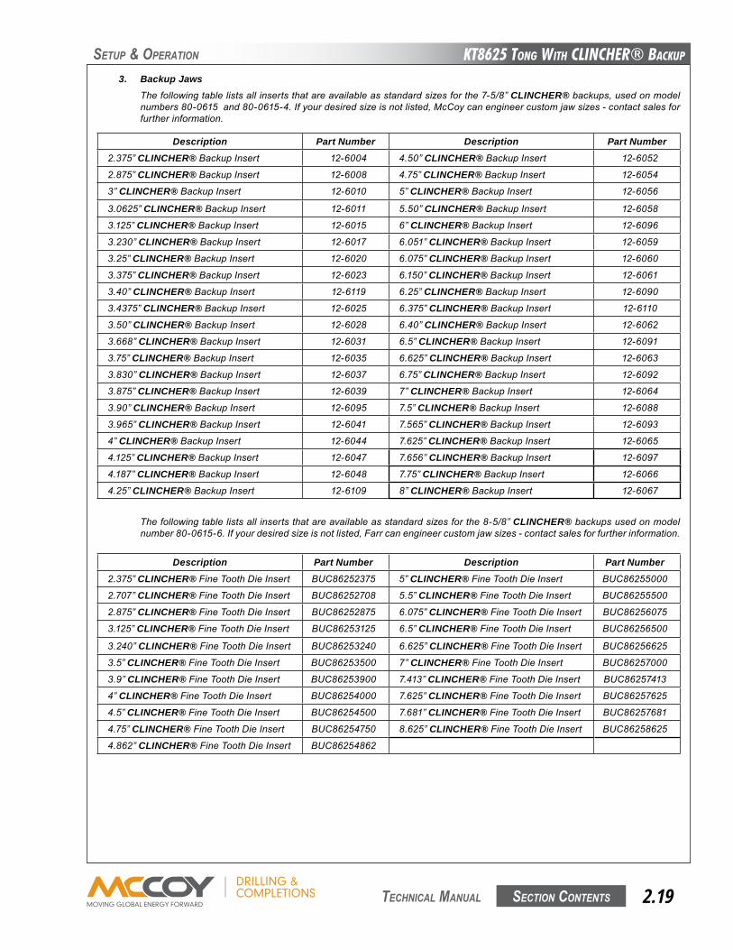
SetuP & oPeRation
3. Backup JawsThefollowingtablelistsallinsertsthatareavailableasstandardsizesforthe7-5/8”CLINCHER®backups,usedonmodelnumbers80-0615and80-0615-4.Ifyourdesiredsizeisnotlisted,McCoycanengineercustomjawsizes-contactsalesforfurtherinformation.
Thefollowingtablelistsallinsertsthatareavailableasstandardsizesforthe8-5/8”CLINCHER®backupsusedonmodelnumber80-0615-6.Ifyourdesiredsizeisnotlisted,Farrcanengineercustomjawsizes-contactsalesforfurtherinformation.
Description Part Number Description Part Number2.375”CLINCHER®FineToothDieInsert BUC86252375 5”CLINCHER®FineToothDieInsert BUC86255000
2.707”CLINCHER®FineToothDieInsert BUC86252708 5.5”CLINCHER®FineToothDieInsert BUC86255500
2.875”CLINCHER®FineToothDieInsert BUC86252875 6.075”CLINCHER®FineToothDieInsert BUC86256075
3.125”CLINCHER®FineToothDieInsert BUC86253125 6.5”CLINCHER®FineToothDieInsert BUC86256500
3.240”CLINCHER®FineToothDieInsert BUC86253240 6.625”CLINCHER®FineToothDieInsert BUC86256625
3.5”CLINCHER®FineToothDieInsert BUC86253500 7”CLINCHER®FineToothDieInsert BUC86257000
3.9”CLINCHER®FineToothDieInsert BUC86253900 7.413”CLINCHER®FineToothDieInsert BUC86257413
4”CLINCHER®FineToothDieInsert BUC86254000 7.625”CLINCHER®FineToothDieInsert BUC86257625
4.5”CLINCHER®FineToothDieInsert BUC86254500 7.681”CLINCHER®FineToothDieInsert BUC86257681
4.75”CLINCHER®FineToothDieInsert BUC86254750 8.625”CLINCHER®FineToothDieInsert BUC86258625
4.862”CLINCHER®FineToothDieInsert BUC86254862
Description Part Number Description Part Number2.375”CLINCHER®BackupInsert 12-6004 4.50”CLINCHER®BackupInsert 12-6052
2.875”CLINCHER®BackupInsert 12-6008 4.75”CLINCHER®BackupInsert 12-6054
3”CLINCHER®BackupInsert 12-6010 5”CLINCHER®BackupInsert 12-6056
3.0625”CLINCHER®BackupInsert 12-6011 5.50”CLINCHER®BackupInsert 12-6058
3.125”CLINCHER®BackupInsert 12-6015 6”CLINCHER®BackupInsert 12-6096
3.230”CLINCHER®BackupInsert 12-6017 6.051”CLINCHER®BackupInsert 12-6059
3.25”CLINCHER®BackupInsert 12-6020 6.075”CLINCHER®BackupInsert 12-6060
3.375”CLINCHER®BackupInsert 12-6023 6.150”CLINCHER®BackupInsert 12-6061
3.40”CLINCHER®BackupInsert 12-6119 6.25”CLINCHER®BackupInsert 12-6090
3.4375”CLINCHER®BackupInsert 12-6025 6.375”CLINCHER®BackupInsert 12-6110
3.50”CLINCHER®BackupInsert 12-6028 6.40”CLINCHER®BackupInsert 12-6062
3.668”CLINCHER®BackupInsert 12-6031 6.5”CLINCHER®BackupInsert 12-6091
3.75”CLINCHER®BackupInsert 12-6035 6.625”CLINCHER®BackupInsert 12-6063
3.830”CLINCHER®BackupInsert 12-6037 6.75”CLINCHER®BackupInsert 12-6092
3.875”CLINCHER®BackupInsert 12-6039 7”CLINCHER®BackupInsert 12-6064
3.90”CLINCHER®BackupInsert 12-6095 7.5”CLINCHER®BackupInsert 12-6088
3.965”CLINCHER®BackupInsert 12-6041 7.565”CLINCHER®BackupInsert 12-6093
4”CLINCHER®BackupInsert 12-6044 7.625”CLINCHER®BackupInsert 12-6065
4.125”CLINCHER®BackupInsert 12-6047 7.656”CLINCHER®BackupInsert 12-6097
4.187”CLINCHER®BackupInsert 12-6048 7.75”CLINCHER®BackupInsert 12-6066
4.25”CLINCHER®BackupInsert 12-6109 8”CLINCHER®BackupInsert 12-6067
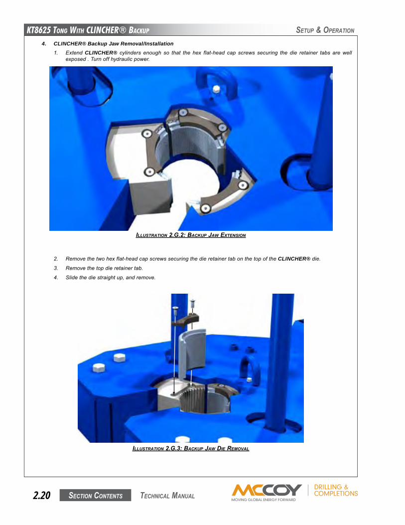
KT8625 Tong WiTh CLinChER® BaCKup
Section contentS2.20 technical Manual
SetuP & oPeRation
4. CLINCHER® Backup Jaw Removal/Installation1. ExtendCLINCHER® cylinders enough so that the hex flat-head cap screws securing the die retainer tabs arewell
exposed.Turnoffhydraulicpower.
ILLUSTRATION 2.g.2: BACKUp JAw ExTENSION
2. Removethetwohexflat-headcapscrewssecuringthedieretainertabonthetopoftheCLINCHER®die.
3. Removethetopdieretainertab.
4. Slidethediestraightup,andremove.
ILLUSTRATION 2.g.3: BACKUp JAw dIE REMOvAL
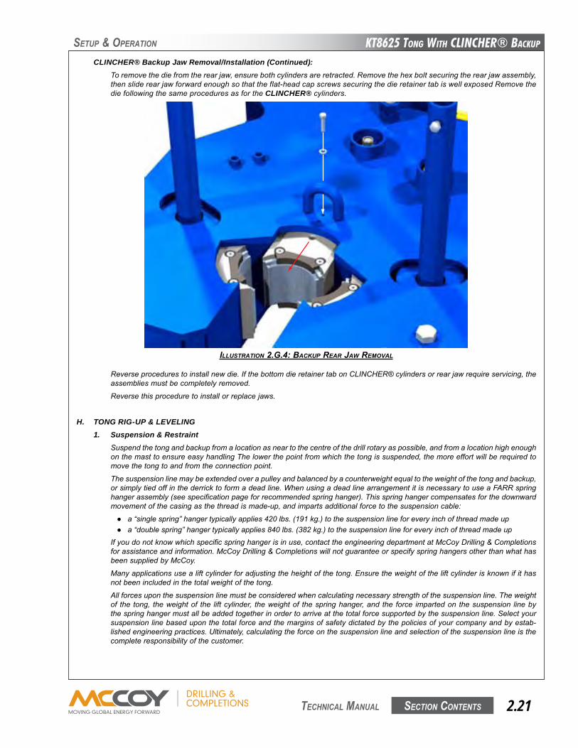
KT8625 Tong WiTh CLinChER® BaCKup
Section contentS 2.21 technical Manual
SetuP & oPeRation
CLINCHER® Backup Jaw Removal/Installation (Continued):Toremovethediefromtherearjaw,ensurebothcylindersareretracted.Removethehexboltsecuringtherearjawassembly,thensliderearjawforwardenoughsothattheflat-headcapscrewssecuringthedieretainertabiswellexposedRemovethediefollowingthesameproceduresasfortheCLINCHER®cylinders.
ILLUSTRATION 2.g.4: BACKUp REAR JAw REMOvAL
Reverseprocedurestoinstallnewdie.IfthebottomdieretainertabonCLINCHER®cylindersorrearjawrequireservicing,theassembliesmustbecompletelyremoved.
Reversethisproceduretoinstallorreplacejaws.
H. TONG RIG-UP & LEVELING1. Suspension & Restraint
Suspendthetongandbackupfromalocationasneartothecentreofthedrillrotaryaspossible,andfromalocationhighenoughonthemasttoensureeasyhandlingThelowerthepointfromwhichthetongissuspended,themoreeffortwillberequiredtomovethetongtoandfromtheconnectionpoint.
Thesuspensionlinemaybeextendedoverapulleyandbalancedbyacounterweightequaltotheweightofthetongandbackup,orsimplytiedoffinthederricktoformadeadline.WhenusingadeadlinearrangementitisnecessarytouseaFARRspringhangerassembly(seespecificationpageforrecommendedspringhanger).Thisspringhangercompensatesforthedownwardmovementofthecasingasthethreadismade-up,andimpartsadditionalforcetothesuspensioncable:
● a“singlespring”hangertypicallyapplies420lbs.(191kg.)tothesuspensionlineforeveryinchofthreadmadeup● a“doublespring”hangertypicallyapplies840lbs.(382kg.)tothesuspensionlineforeveryinchofthreadmadeup
Ifyoudonotknowwhichspecificspringhangerisinuse,contacttheengineeringdepartmentatMcCoyDrilling&Completionsforassistanceandinformation.McCoyDrilling&CompletionswillnotguaranteeorspecifyspringhangersotherthanwhathasbeensuppliedbyMcCoy.
Manyapplicationsusealiftcylinderforadjustingtheheightofthetong.Ensuretheweightoftheliftcylinderisknownifithasnotbeenincludedinthetotalweightofthetong.
Allforcesuponthesuspensionlinemustbeconsideredwhencalculatingnecessarystrengthofthesuspensionline.Theweightof the tong, theweightof the liftcylinder, theweightof thespringhanger,andthe force impartedonthesuspension linebythespringhangermustallbeaddedtogetherinordertoarriveatthetotalforcesupportedbythesuspensionline.Selectyoursuspensionlinebaseduponthetotalforceandthemarginsofsafetydictatedbythepoliciesofyourcompanyandbyestab-lishedengineeringpractices.Ultimately,calculatingtheforceonthesuspensionlineandselectionofthesuspensionlineisthecompleteresponsibilityofthecustomer.
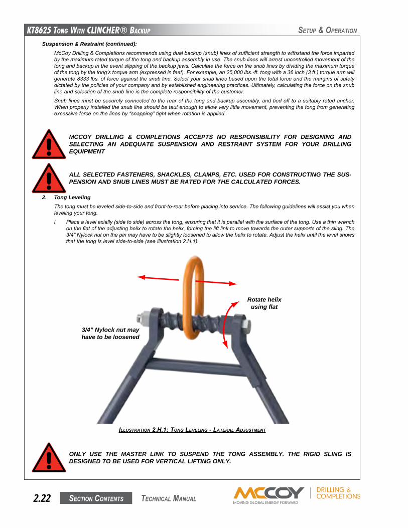
KT8625 Tong WiTh CLinChER® BaCKup
Section contentS2.22 technical Manual
SetuP & oPeRation
Suspension & Restraint (continued):McCoyDrilling&Completionsrecommendsusingdualbackup(snub)linesofsufficientstrengthtowithstandtheforceimpartedbythemaximumratedtorqueofthetongandbackupassemblyinuse.Thesnublineswillarrestuncontrolledmovementofthetongandbackupintheeventslippingofthebackupjaws.Calculatetheforceonthesnublinesbydividingthemaximumtorqueofthetongbythetong’storquearm(expressedinfeet).Forexample,an25,000lbs.-ft.tongwitha36inch(3ft.)torquearmwillgenerate8333lbs.offorceagainstthesnubline.Selectyoursnublinesbaseduponthetotalforceandthemarginsofsafetydictatedbythepoliciesofyourcompanyandbyestablishedengineeringpractices.Ultimately,calculatingtheforceonthesnublineandselectionofthesnublineisthecompleteresponsibilityofthecustomer.
Snublinesmustbesecurelyconnectedtotherearofthetongandbackupassembly,andtiedofftoasuitablyratedanchor.Whenproperlyinstalledthesnublineshouldbetautenoughtoallowverylittlemovement,preventingthetongfromgeneratingexcessiveforceonthelinesby“snapping”tightwhenrotationisapplied.
MCCOY DRILLING & COMPLETIONS ACCEPTS NO RESPONSIBILITY FOR DESIGNING AND SELECTING AN ADEQUATE SUSPENSION AND RESTRAINT SYSTEM FOR YOUR DRILLING EQUIPMENT
ALL SELECTED FASTENERS, SHACKLES, CLAMPS, ETC. USED FOR CONSTRUCTING THE SUS-PENSION AND SNUB LINES MUST BE RATED FOR THE CALCULATED FORCES.
2. Tong LevelingThetongmustbeleveledside-to-sideandfront-to-rearbeforeplacingintoservice.Thefollowingguidelineswillassistyouwhenlevelingyourtong.
i. Placealevelaxially(sidetoside)acrossthetong,ensuringthatitisparallelwiththesurfaceofthetong.Useathinwrenchontheflatoftheadjustinghelixtorotatethehelix,forcingtheliftlinktomovetowardstheoutersupportsofthesling.The3/4”Nylocknutonthepinmayhavetobeslightlyloosenedtoallowthehelixtorotate.Adjustthehelixuntilthelevelshowsthatthetongislevelside-to-side(seeillustration2.H.1).
ILLUSTRATION 2.H.1: TONg LEvELINg - LATERAL AdJUSTMENT
ONLY USE THE MASTER LINK TO SUSPEND THE TONG ASSEMBLY. THE RIGID SLING IS DESIGNED TO BE USED FOR VERTICAL LIFTING ONLY.
3/4” Nylock nut may have to be loosened
Rotate helix using flat
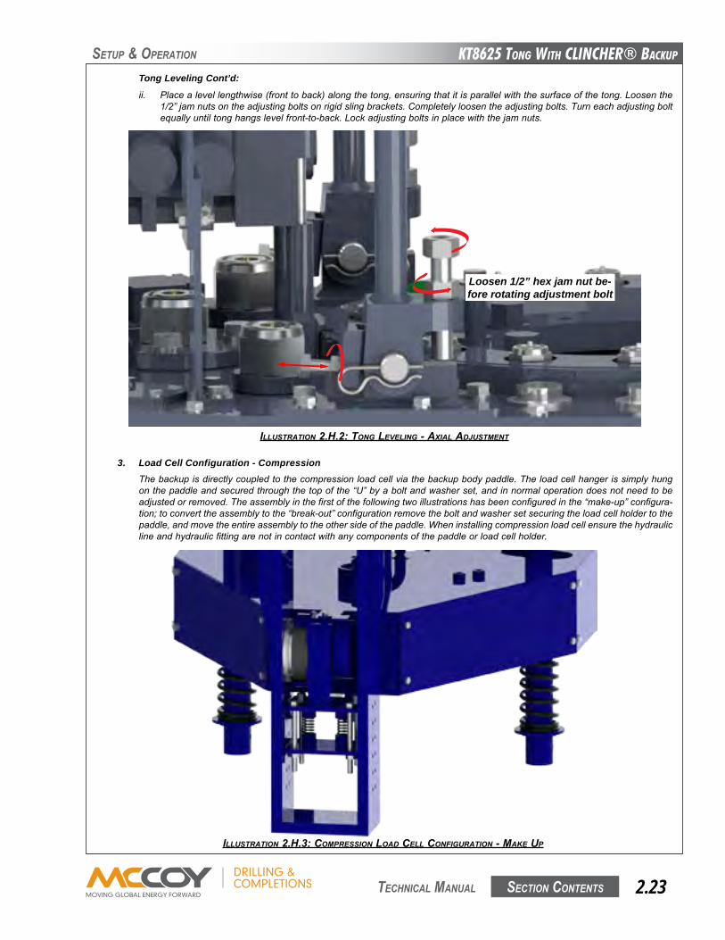
KT8625 Tong WiTh CLinChER® BaCKup
Section contentS 2.23 technical Manual
SetuP & oPeRation
Tong Leveling Cont’d:
ii. Placealevellengthwise(fronttoback)alongthetong,ensuringthatitisparallelwiththesurfaceofthetong.Loosenthe1/2”jamnutsontheadjustingboltsonrigidslingbrackets.Completelyloosentheadjustingbolts.Turneachadjustingboltequallyuntiltonghangslevelfront-to-back.Lockadjustingboltsinplacewiththejamnuts.
ILLUSTRATION 2.H.2: TONg LEvELINg - AxIAL AdJUSTMENT
3. Load Cell Configuration - CompressionThebackupisdirectlycoupledtothecompressionloadcellviathebackupbodypaddle.Theloadcellhangerissimplyhungonthepaddleandsecuredthroughthetopofthe“U”byaboltandwasherset,andinnormaloperationdoesnotneedtobeadjustedorremoved.Theassemblyinthefirstofthefollowingtwoillustrationshasbeenconfiguredinthe“make-up”configura-tion;toconverttheassemblytothe“break-out”configurationremovetheboltandwashersetsecuringtheloadcellholdertothepaddle,andmovetheentireassemblytotheothersideofthepaddle.Wheninstallingcompressionloadcellensurethehydrauliclineandhydraulicfittingarenotincontactwithanycomponentsofthepaddleorloadcellholder.
ILLUSTRATION 2.H.3: COMpRESSION LOAd CELL CONFIgURATION - MAKE Up
Loosen 1/2” hex jam nut be-fore rotating adjustment bolt
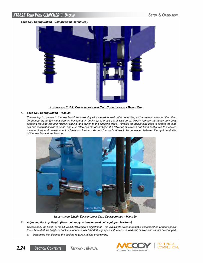
KT8625 Tong WiTh CLinChER® BaCKup
Section contentS2.24 technical Manual
SetuP & oPeRation
ILLUSTRATION 2.H.4: COMpRESSION LOAd CELL CONFIgURATION - BREAK OUT
Load Cell Configuration - Compression (continued):
4. Load Cell Configuration - TensionThebackupiscoupledtotherearlegoftheassemblywithatensionloadcellononeside,andarestraintchainontheother.Tochange the torquemeasurementconfiguration (makeup tobreakoutorvisaversa)simply remove theheavydutyboltssecuringtheloadcellandrestraintchains,andswitchtotheoppositesides.Reinstalltheheavydutyboltstosecuretheloadcellandrestraintchainsinplace.Foryourreferencetheassemblyinthefollowingillustrationhasbeenconfiguredtomeasuremakeuptorque.Ifmeasurementofbreakouttorqueisdesiredtheloadcellwouldbeconnectedbetweentherighthandsideoftherearlegandthebackup.
ILLUSTRATION 2.H.5: TENSION LOAd CELL CONFIgURATION - MAKE Up
5. Adjusting Backup Height (Does not apply to tension load cell equipped backups)OccasionallytheheightoftheCLINCHER®requiresadjustment.Thisisasimpleprocedurethatisaccomplishedwithoutspecialtools.Notethattheheightofbackupmodelnumber85-0606,equippedwithatensionloadcell,isfixedandcannotbechanged.
a. Determinethedistancethebackuprequiresraisingorlowering.
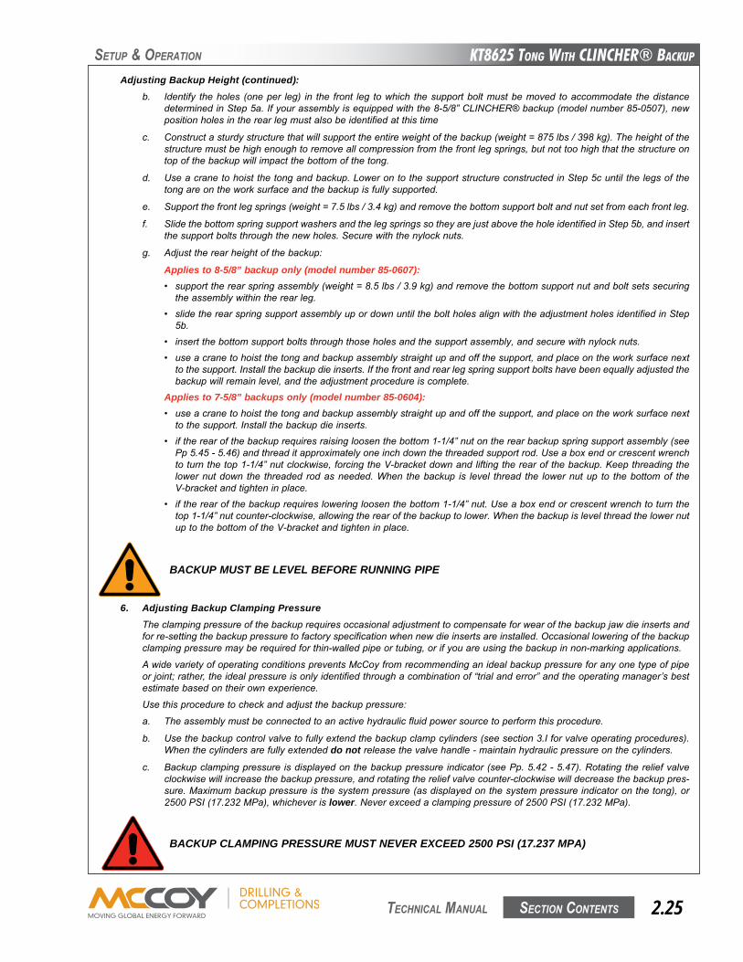
KT8625 Tong WiTh CLinChER® BaCKup
Section contentS 2.25 technical Manual
Adjusting Backup Height (continued):b. Identify theholes (oneper leg) in the front leg towhich thesupportboltmustbemoved toaccommodate thedistance
determinedinStep5a.Ifyourassemblyisequippedwiththe8-5/8”CLINCHER®backup(modelnumber85-0507),newpositionholesintherearlegmustalsobeidentifiedatthistime
c. Constructasturdystructurethatwillsupporttheentireweightofthebackup(weight=875lbs/398kg).Theheightofthestructuremustbehighenoughtoremoveallcompressionfromthefrontlegsprings,butnottoohighthatthestructureontopofthebackupwillimpactthebottomofthetong.
d. Useacranetohoistthetongandbackup.LowerontothesupportstructureconstructedinStep5cuntilthelegsofthetongareontheworksurfaceandthebackupisfullysupported.
e. Supportthefrontlegsprings(weight=7.5lbs/3.4kg)andremovethebottomsupportboltandnutsetfromeachfrontleg.
f. SlidethebottomspringsupportwashersandthelegspringssotheyarejustabovetheholeidentifiedinStep5b,andinsertthesupportboltsthroughthenewholes.Securewiththenylocknuts.
g. Adjusttherearheightofthebackup:
Applies to 8-5/8” backup only (model number 85-0607):• supporttherearspringassembly(weight=8.5lbs/3.9kg)andremovethebottomsupportnutandboltsetssecuringtheassemblywithintherearleg.
• slidetherearspringsupportassemblyupordownuntiltheboltholesalignwiththeadjustmentholesidentifiedinStep5b.
• insertthebottomsupportboltsthroughthoseholesandthesupportassembly,andsecurewithnylocknuts.
• useacranetohoistthetongandbackupassemblystraightupandoffthesupport,andplaceontheworksurfacenexttothesupport.Installthebackupdieinserts.Ifthefrontandrearlegspringsupportboltshavebeenequallyadjustedthebackupwillremainlevel,andtheadjustmentprocedureiscomplete.
Applies to 7-5/8” backups only (model number 85-0604):• useacranetohoistthetongandbackupassemblystraightupandoffthesupport,andplaceontheworksurfacenexttothesupport.Installthebackupdieinserts.
• iftherearofthebackuprequiresraisingloosenthebottom1-1/4”nutontherearbackupspringsupportassembly(seePp5.45-5.46)andthreaditapproximatelyoneinchdownthethreadedsupportrod.Useaboxendorcrescentwrenchtoturnthetop1-1/4”nutclockwise,forcingtheV-bracketdownandliftingtherearofthebackup.Keepthreadingthelowernutdown the threaded rodasneeded.When thebackup is level thread the lowernutup to thebottomof theV-bracketandtighteninplace.
• iftherearofthebackuprequiresloweringloosenthebottom1-1/4”nut.Useaboxendorcrescentwrenchtoturnthetop1-1/4”nutcounter-clockwise,allowingtherearofthebackuptolower.WhenthebackupislevelthreadthelowernutuptothebottomoftheV-bracketandtighteninplace.
SetuP & oPeRation
BACKUP MUST BE LEVEL BEFORE RUNNING PIPE
6. Adjusting Backup Clamping PressureTheclampingpressureofthebackuprequiresoccasionaladjustmenttocompensateforwearofthebackupjawdieinsertsandforre-settingthebackuppressuretofactoryspecificationwhennewdieinsertsareinstalled.Occasionalloweringofthebackupclampingpressuremayberequiredforthin-walledpipeortubing,orifyouareusingthebackupinnon-markingapplications.
AwidevarietyofoperatingconditionspreventsMcCoyfromrecommendinganidealbackuppressureforanyonetypeofpipeorjoint;rather,theidealpressureisonlyidentifiedthroughacombinationof“trialanderror”andtheoperatingmanager’sbestestimatebasedontheirownexperience.
Usethisproceduretocheckandadjustthebackuppressure:
a. Theassemblymustbeconnectedtoanactivehydraulicfluidpowersourcetoperformthisprocedure.
b. Usethebackupcontrolvalvetofullyextendthebackupclampcylinders(seesection3.Iforvalveoperatingprocedures).Whenthecylindersarefullyextendeddo notreleasethevalvehandle-maintainhydraulicpressureonthecylinders.
c. Backupclampingpressureisdisplayedonthebackuppressureindicator(seePp.5.42-5.47).Rotatingthereliefvalveclockwisewillincreasethebackuppressure,androtatingthereliefvalvecounter-clockwisewilldecreasethebackuppres-sure.Maximumbackuppressureisthesystempressure(asdisplayedonthesystempressureindicatoronthetong),or2500PSI(17.232MPa),whicheverislower.Neverexceedaclampingpressureof2500PSI(17.232MPa).
BACKUP CLAMPING PRESSURE MUST NEVER EXCEED 2500 PSI (17.237 MPA)
KT8625 Tong WiTh CLinChER® BaCKup
Section contentS2.26 technical Manual
ALWAYS WEAR APPROVED PERSONAL PROTECTIVE EQUIPMENT (PPE) WHEN OPERATING HYDRAULICALLY-POWERED EQUIPMENT.
Ensurehydraulicpower isdeactivatedandtonghydraulicsarede-pressurizedbeforedisconnectingthemainhydraulic lines.McCoyrecommendsdepressurizingthetonghydraulicsystembeforeconnectingordisconnectingquick-connectfittings.
DEPRESSURIZE EQUIPMENT BEFORE DISCONNECTING MAIN HYDRAULIC LINES.
Theareasurroundingthetongoperatingareamustbeclutter-freeandfreefromtrippinghazards,orprotrudingobjectsthatmaysnaghydraulichosesonthetong,backup,liftcylinder,ortorquemeasurementsystem.Operatingsurfaceordrillfloormustbekeptfreeofslippinghazardslikegrease,oil,water,etc.
Adequatelightingoftheworkareaisrequired.Allwarnings,labels,gauges,andsignsmustbeclearlyvisible
Thecomponentsofthetongcommonlymanipulatedorrequiringcontrolinputarepaintedgreen,andaresafeforcontinuoushandling.Areas painted yellow are designated as hazardous areas, and contact with those areasmust be avoided duringoperation.Alwayswearallpersonalprotectiveequipment(PPE)specifiedbyyourcompany’sHSEpolicy,andfollowallofyourcompany’ssafetyguidelines.
SetuP & oPeRation
Inspectanti-tamperdevicesonsafetydoorcomponentsbeforebeginningjob.Equipmentshowingsignsoftamperingonanysafetysystemmustbeimmediatelyremovedfromserviceandtested.Anti-tamperdevicesmustberestoredbeforeallowingequipmenttobereleasedtoanoperatingenvironment.
Adjusting Backup Clamping Pressure (continued):d. Whenthedesiredpressurehasbeensetreleasethepressuretothebackupcylinders,andusethebackupclampingvalve
toretractthecylinders.
e. Performenoughtestconnectionstodeterminethatthebackuppressureisadequateformakingupandbreakingoutjointswithinthecurrentapplication.Ifpipeslippageorcrushingisobservedrepeatthebackuppressureadjustmentprocedure.
I. TONG OPERATION1. Operator Training
Manycompaniessetqualificationstandardsthatmustbemetbeforeequipmentmaybeoperatedwithoutsupervision.McCoyDrilling&Completionsrecommendsoperatortraining,whichtypicallyconsistsofoperationoftheequipmentunderthesupervi-sionofatrainedequipmentoperatoruntilasatisfactorylevelofcompetenceisachieved.Typicaloperatortrainingshouldinclude:
• Introductiontoandgeneraldescriptionofequipment• Technicalspecificationsandperformancedata• Operatinginstructions• Controlsystemsandinterlocks• Operatinghazards• Checksandinspections• Hoistingandliftingdevicetraining
2. Operator SafetyMcCoyrecommendsthatahazardassessmentof theworkareabeperformedbyadesignatedsafetyrepresentativebeforecommencingoperations.Adesignatedsafetyrepresentativeisresponsibleforverifyingthatalloperatorshaveadequateequip-mentandsafetytraining.
Thesafetydoorsystemistheprimarydeviceprotectingthetongoperatorandnearbypersonnelfromtherotarygear.Confirmthecorrectoperationofthesafetydoorbeforeeveryjob.Neverdisablethesafetydoordevice.
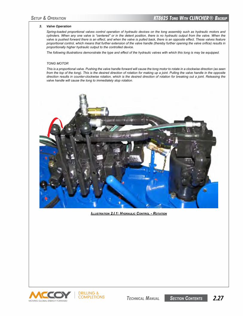
KT8625 Tong WiTh CLinChER® BaCKup
Section contentS 2.27 technical Manual
SetuP & oPeRation
ILLUSTRATION 2.I.1: HydRAULIC CONTROL - ROTATION
3. Valve OperationSpring-loadedproportionalvalvescontroloperationofhydraulicdevicesonthetongassemblysuchashydraulicmotorsandcylinders.Whenanyonevalve is “centered”or in thedetentposition, there isnohydraulicoutput fromthevalve.When thevalveispushedforwardthereisaneffect,andwhenthevalveispulledback,thereisanoppositeeffect.Thesevalvesfeatureproportionalcontrol,whichmeansthatfurtherextensionofthevalvehandle(therebyfurtheropeningthevalveorifice)resultsinproportionallyhigherhydraulicoutputtothecontrolleddevice.
Thefollowingillustrationsdemonstratethetypeandeffectofthehydraulicvalveswithwhichthistongismaybeequipped.
TONGMOTOR
Thisisaproportionalvalve.Pushingthevalvehandleforwardwillcausethetongmotortorotateinaclockwisedirection(asseenfromthetopofthetong).Thisisthedesireddirectionofrotationformakingupajoint.Pullingthevalvehandleintheoppositedirectionresultsincounter-clockwiserotation,whichisthedesireddirectionofrotationforbreakingoutajoint.Releasingthevalvehandlewillcausethetongtoimmediatelystoprotation.
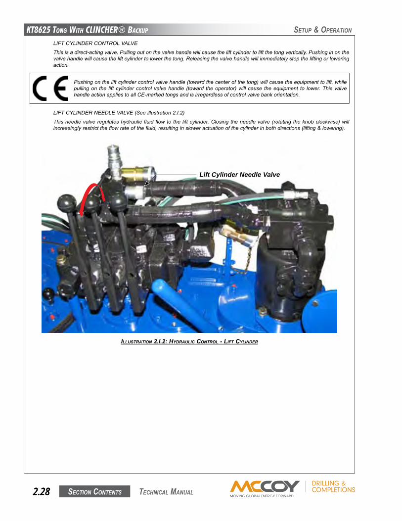
KT8625 Tong WiTh CLinChER® BaCKup
Section contentS2.28 technical Manual
SetuP & oPeRation
LIFTCYLINDERCONTROLVALVE
Thisisadirect-actingvalve.Pullingoutonthevalvehandlewillcausetheliftcylindertoliftthetongvertically.Pushinginonthevalvehandlewillcausetheliftcylindertolowerthetong.Releasingthevalvehandlewillimmediatelystoptheliftingorloweringaction.
Pushingontheliftcylindercontrolvalvehandle(towardthecenterofthetong)willcausetheequipmenttolift,whilepullingon the lift cylindercontrolvalvehandle (toward theoperator)will cause theequipment to lower.ThisvalvehandleactionappliestoallCE-markedtongsandisirregardlessofcontrolvalvebankorientation.
LIFTCYLINDERNEEDLEVALVE(Seeillustration2.I.2)
Thisneedlevalveregulateshydraulic fluid flowtothe liftcylinder.Closingtheneedlevalve(rotatingtheknobclockwise)willincreasinglyrestricttheflowrateofthefluid,resultinginsloweractuationofthecylinderinbothdirections(lifting&lowering).
ILLUSTRATION 2.I.2: HydRAULIC CONTROL - LIFT CyLINdER
Lift Cylinder Needle Valve
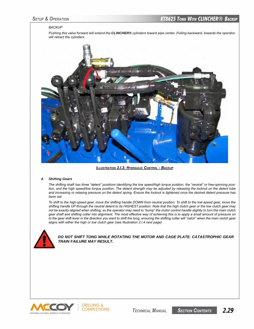
KT8625 Tong WiTh CLinChER® BaCKup
Section contentS 2.29 technical Manual
SetuP & oPeRation
BACKUP
PushingthisvalveforwardwillextendtheCLINCHER®cylinderstowardpipecenter.Pullingbackward,towardstheoperator,willretractthecylinders.
ILLUSTRATION 2.I.3: HydRAULIC CONTROL - BACKUp
4. Shifting GearsTheshiftingshafthasthree“detent”positionsidentifyingthelowspeed/hightorqueposition,the“neutral”orfree-spinningposi-tion,andthehighspeed/lowtorqueposition.Thedetentstrengthmaybeadjustedbyreleasingthelocknutonthedetenttubeandincreasingorrelaxingpressureonthedetentspring.Ensurethelocknutistightenedoncethedesireddetentpressurehasbeenset.
Toshifttothehigh-speedgear,movetheshiftinghandleDOWNfromneutralposition.Toshifttothelow-speedgear,movetheshiftinghandleUPthroughtheneutraldetenttoitsHIGHESTposition.Notethatthehighclutchgearorthelowclutchgearmaynotbeexactlyalignedwhenshifting,sotheoperatormayneedto“bump”themotorcontrolhandleslightlytoturnthemainclutchgearshaftandshiftingcollarintoalignment.Themosteffectivewayofachievingthisistoapplyasmallamountofpressureontothegearshiftleverinthedirectionyouwanttoshiftthetong,ensuringtheshiftingcollarwill“catch”whenthemainclutchgearalignswitheitherthehighorlowclutchgear(seeIllustration2.I.4nextpage)
DO NOT SHIFT TONG WHILE ROTATING THE MOTOR AND CAGE PLATE. CATASTROPHIC GEAR TRAIN FAILURE MAY RESULT.
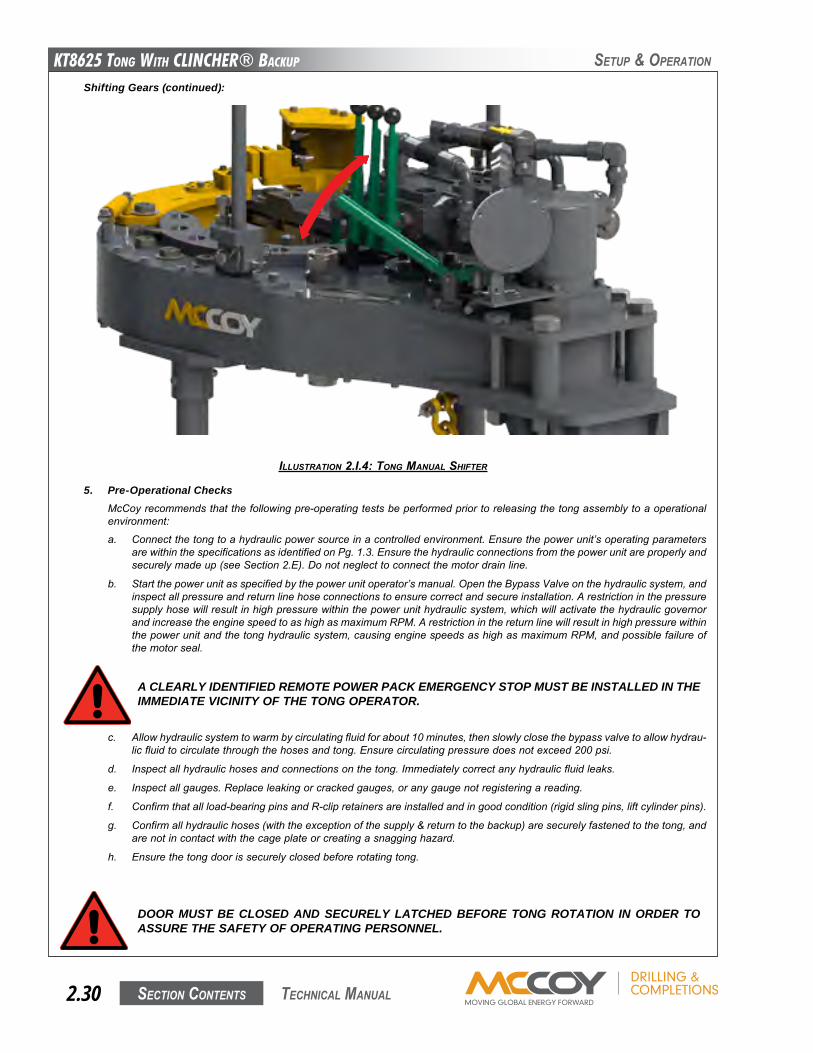
KT8625 Tong WiTh CLinChER® BaCKup
Section contentS2.30 technical Manual
SetuP & oPeRation
ILLUSTRATION 2.I.4: TONg MANUAL SHIFTER
5. Pre-Operational ChecksMcCoyrecommendsthatthefollowingpre-operatingtestsbeperformedpriortoreleasingthetongassemblytoaoperationalenvironment:
a. Connectthetongtoahydraulicpowersourceinacontrolledenvironment.Ensurethepowerunit’soperatingparametersarewithinthespecificationsasidentifiedonPg.1.3.Ensurethehydraulicconnectionsfromthepowerunitareproperlyandsecurelymadeup(seeSection2.E).Donotneglecttoconnectthemotordrainline.
b. Startthepowerunitasspecifiedbythepowerunitoperator’smanual.OpentheBypassValveonthehydraulicsystem,andinspectallpressureandreturnlinehoseconnectionstoensurecorrectandsecureinstallation.Arestrictioninthepressuresupplyhosewillresultinhighpressurewithinthepowerunithydraulicsystem,whichwillactivatethehydraulicgovernorandincreasetheenginespeedtoashighasmaximumRPM.Arestrictioninthereturnlinewillresultinhighpressurewithinthepowerunitandthetonghydraulicsystem,causingenginespeedsashighasmaximumRPM,andpossiblefailureofthemotorseal.
A CLEARLY IDENTIFIED REMOTE POWER PACK EMERGENCY STOP MUST BE INSTALLED IN THE IMMEDIATE VICINITY OF THE TONG OPERATOR.
c. Allowhydraulicsystemtowarmbycirculatingfluidforabout10minutes,thenslowlyclosethebypassvalvetoallowhydrau-licfluidtocirculatethroughthehosesandtong.Ensurecirculatingpressuredoesnotexceed200psi.
d. Inspectallhydraulichosesandconnectionsonthetong.Immediatelycorrectanyhydraulicfluidleaks.
e. Inspectallgauges.Replaceleakingorcrackedgauges,oranygaugenotregisteringareading.
f. Confirmthatallload-bearingpinsandR-clipretainersareinstalledandingoodcondition(rigidslingpins,liftcylinderpins).
g. Confirmallhydraulichoses(withtheexceptionofthesupply&returntothebackup)aresecurelyfastenedtothetong,andarenotincontactwiththecageplateorcreatingasnagginghazard.
h. Ensurethetongdoorissecurelyclosedbeforerotatingtong.
DOOR MUST BE CLOSED AND SECURELY LATCHED BEFORE TONG ROTATION IN ORDER TO ASSURE THE SAFETY OF OPERATING PERSONNEL.
Shifting Gears (continued):
KT8625 Tong WiTh CLinChER® BaCKup
Section contentS 2.31 technical Manual
SetuP & oPeRation
Pre-Operational Checks (continued):i. Shiftthetongtolowgear(seeSection2.I.3)androtatethetongslowlyforwardforapproximatelyaminute.Stopthetong
andthenreversetherotationdirectionforapproximatelyanotherminute.Stopthetong,shifttohighgear,andoperateinhighgearforapproximatelyanotherminute.Stopthetongandrotateintheoppositedirectioninhighgearforapproximatelyanotherminute.Ifatanytimeabnormaloperationissuspected(surging,grinding,squealing,orothernoisesdeemedtobeunusual,orfailuretooperate)discontinueoperationofthetongandcontactMcCoyDrilling&Completionsimmediately.
j. Re-inspectallhydrauliclinesandconnectionsonthetong,andcorrectallleaks.
k. Thesafetydoorsystemistheprimeprotectivemeasureseparatingtheoperatorfromtherotarygear,andmustbeinwork-ingconditionwhenoperatingtong.Carefullyinspectthesafetydoorcomponents,andtesttheoperationofthesafetydoorusingthefollowingprocedure:
i. Keepnon-essentialpersonnelclearoftheunitundertest.Thistestprocedurewillonlyincludetwopeople:onetorunthecontrolvalveandonetooperatethedoor.
ii. Ensurethetongdoorissecurelyclosed.
iii. ShifttoLOWgear.
iv. Beginrotatingthetong(directionofrotationisnotimportant).
v. Openthetongdoorwhiletherotatingthetong.Thetongmustimmediatelyandcompletelystoprotatingassoonasthedoorisopened.
vi. Continuetoapplyrotationcontrol,andopen&closethedoorthroughoutitscompleterange.Slowlyclosethedooruntilitlatches.Rotationmustnotbeginuntilthedooriscompletelyclosedandsecurelylatched.
Ifthesafetydoordoesnotoperateasdesigned,thesafetydoorswitchmayrequireadjustment,orfurthertroubleshootingofthesafetydoorsystemmayberequired.SeeSection3.F.4forsafetydoorswitchadjustmentprocedures,andSection4.Dforsafetydoortroubleshootinginstructions.
Thesafetydoorswitch isprotectedfromimpactbyasturdymetalguard,paintedyellow.Thisguardmustbe inspectedbeforeeachuseofthetong.Allcomponentsoftheguardmustbeinplace,andallfastenerssecuringtheguardmustbeintactandtight.Ensurewireties(whereapplicable)onsafetydoorcomponentsarepresentandsecure,anddonotshowsignsoftampering.
6. General Commentsa) Positionrotarygearincontactwithbothidlergearswhenmakinguporbreakingoutjointsorcollarswhentorqueinexcess
of50%oftheratedtorqueisrequired.
b) Whenmaking-upintegral(shouldered)joints,itisessentialtomakeupthelastturnofthethreadsinlowgear.Thisreducesthetendencyofaninstantstoporasuddenincreaseintorque,whichinducesextremelyhighstressuponthegeartrain.
c) DONOTemploy the “snap break”method of breaking-out jointswhen pulling a string.By definition, the “snap break”methodisaprocedureusedbysomeoperatorstobreakoutconnections,accomplishedbyleavingslackinthe“jaw-pipe”engagement,andthenquicklypullingthethrottlevalvecontrolleverallowingthetongtosnapintoitsloadedorhightorquecondition.Theextremelyhighstressplacedonthegeartrainfrequentlycausesgearbreakage.
DO NOT USE THE “SNAP BREAK” METHOD TO BREAK OUT JOINTS
DO NOT OPERATE TONG WITH A MALFUNCTIONING OR NON-OPERATING SAFETY DOOR SYS-TEM.
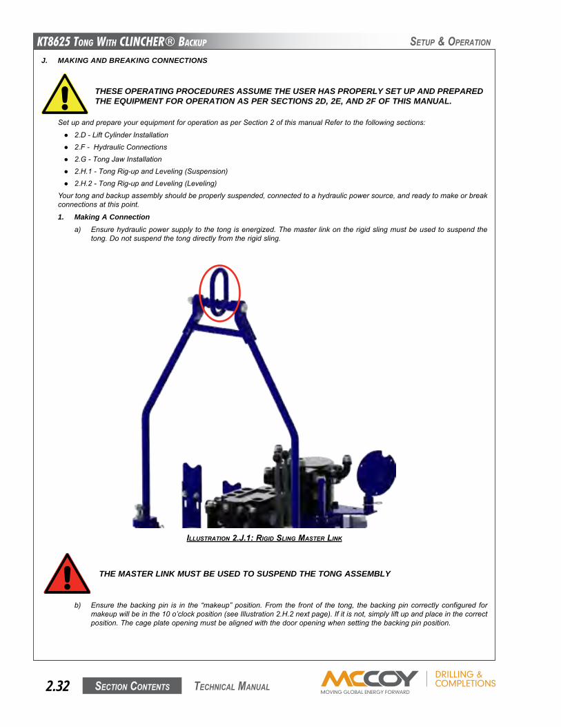
KT8625 Tong WiTh CLinChER® BaCKup
Section contentS2.32 technical Manual
SetuP & oPeRation
J. MAKING AND BREAKING CONNECTIONS
SetupandprepareyourequipmentforoperationasperSection2ofthismanualRefertothefollowingsections:
● 2.D-LiftCylinderInstallation● 2.F-HydraulicConnections● 2.G-TongJawInstallation● 2.H.1-TongRig-upandLeveling(Suspension)● 2.H.2-TongRig-upandLeveling(Leveling)
Yourtongandbackupassemblyshouldbeproperlysuspended,connectedtoahydraulicpowersource,andreadytomakeorbreakconnectionsatthispoint.
1. Making A Connectiona) Ensurehydraulicpowersupplytothetongisenergized.Themasterlinkontherigidslingmustbeusedtosuspendthe
tong.Donotsuspendthetongdirectlyfromtherigidsling.
THESE OPERATING PROCEDURES ASSUME THE USER HAS PROPERLY SET UP AND PREPARED THE EQUIPMENT FOR OPERATION AS PER SECTIONS 2D, 2E, AND 2F OF THIS MANUAL.
THE MASTER LINK MUST BE USED TO SUSPEND THE TONG ASSEMBLY
b) Ensure thebackingpin is in the “makeup”position.From the frontof the tong, thebackingpincorrectlyconfigured formakeupwillbeinthe10o’clockposition(seeIllustration2.H.2nextpage).Ifitisnot,simplyliftupandplaceinthecorrectposition.Thecageplateopeningmustbealignedwiththedooropeningwhensettingthebackingpinposition.
ILLUSTRATION 2.J.1: RIgId SLINg MASTER LINK
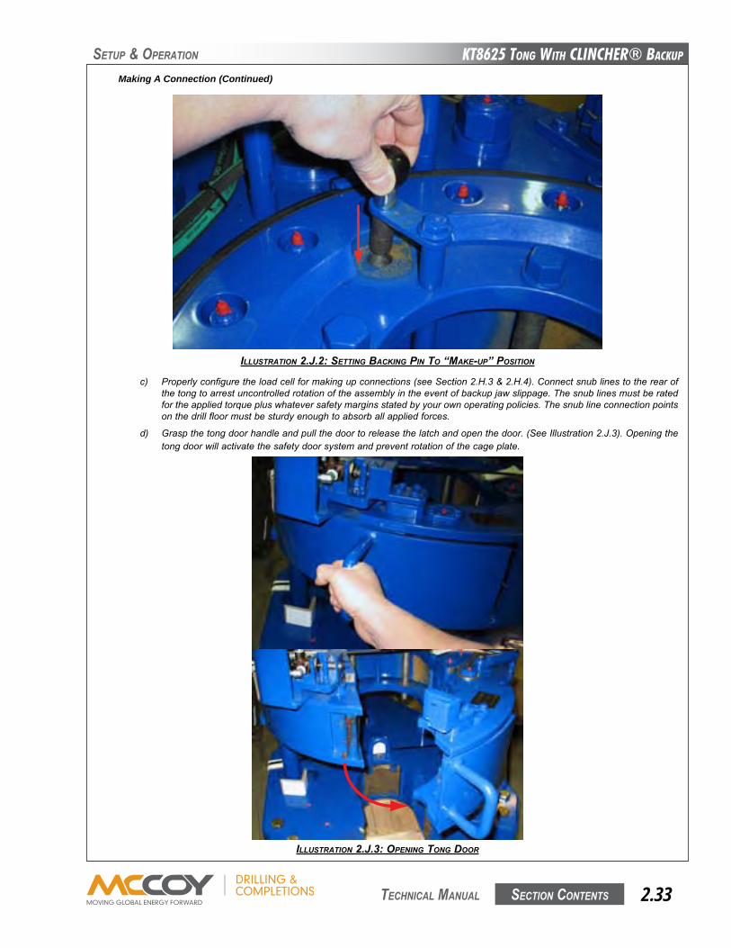
KT8625 Tong WiTh CLinChER® BaCKup
Section contentS 2.33 technical Manual
SetuP & oPeRation
Making A Connection (Continued)
ILLUSTRATION 2.J.2: SETTINg BACKINg pIN TO “MAKE-Up” pOSITION
c) Properlyconfiguretheloadcellformakingupconnections(seeSection2.H.3&2.H.4).Connectsnublinestotherearofthetongtoarrestuncontrolledrotationoftheassemblyintheeventofbackupjawslippage.Thesnublinesmustberatedfortheappliedtorquepluswhateversafetymarginsstatedbyyourownoperatingpolicies.Thesnublineconnectionpointsonthedrillfloormustbesturdyenoughtoabsorballappliedforces.
d) Graspthetongdoorhandleandpullthedoortoreleasethelatchandopenthedoor.(SeeIllustration2.J.3).Openingthetongdoorwillactivatethesafetydoorsystemandpreventrotationofthecageplate.
ILLUSTRATION 2.J.3: OpENINg TONg dOOR
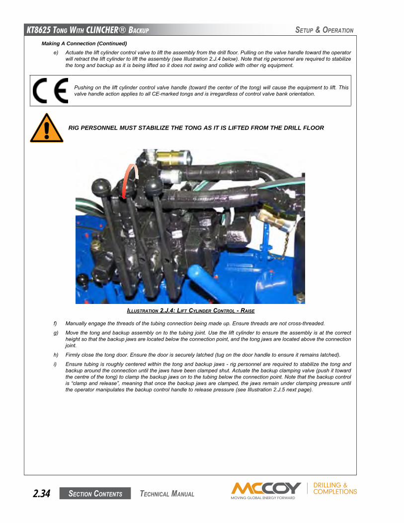
KT8625 Tong WiTh CLinChER® BaCKup
Section contentS2.34 technical Manual
SetuP & oPeRation
RIG PERSONNEL MUST STABILIZE THE TONG AS IT IS LIFTED FROM THE DRILL FLOOR
ILLUSTRATION 2.J.4: LIFT CyLINdER CONTROL - RAISE
Making A Connection (Continued) e) Actuatetheliftcylindercontrolvalvetolifttheassemblyfromthedrillfloor.Pullingonthevalvehandletowardtheoperator
willretracttheliftcylindertolifttheassembly(seeIllustration2.J.4below).Notethatrigpersonnelarerequiredtostabilizethetongandbackupasitisbeingliftedsoitdoesnotswingandcollidewithotherrigequipment.
f) Manuallyengagethethreadsofthetubingconnectionbeingmadeup.Ensurethreadsarenotcross-threaded.
g) Movethetongandbackupassemblyontothetubingjoint.Usetheliftcylindertoensuretheassemblyisatthecorrectheightsothatthebackupjawsarelocatedbelowtheconnectionpoint,andthetongjawsarelocatedabovetheconnectionjoint.
h) Firmlyclosethetongdoor.Ensurethedoorissecurelylatched(tugonthedoorhandletoensureitremainslatched).
i) Ensuretubingisroughlycenteredwithinthetongandbackupjaws-rigpersonnelarerequiredtostabilizethetongandbackuparoundtheconnectionuntilthejawshavebeenclampedshut.Actuatethebackupclampingvalve(pushittowardthecentreofthetong)toclampthebackupjawsontothetubingbelowtheconnectionpoint.Notethatthebackupcontrolis“clampandrelease”,meaningthatoncethebackupjawsareclamped,thejawsremainunderclampingpressureuntiltheoperatormanipulatesthebackupcontrolhandletoreleasepressure(seeIllustration2.J.5nextpage).
Pushingontheliftcylindercontrolvalvehandle(towardthecenterofthetong)willcausetheequipmenttolift.ThisvalvehandleactionappliestoallCE-markedtongsandisirregardlessofcontrolvalvebankorientation.
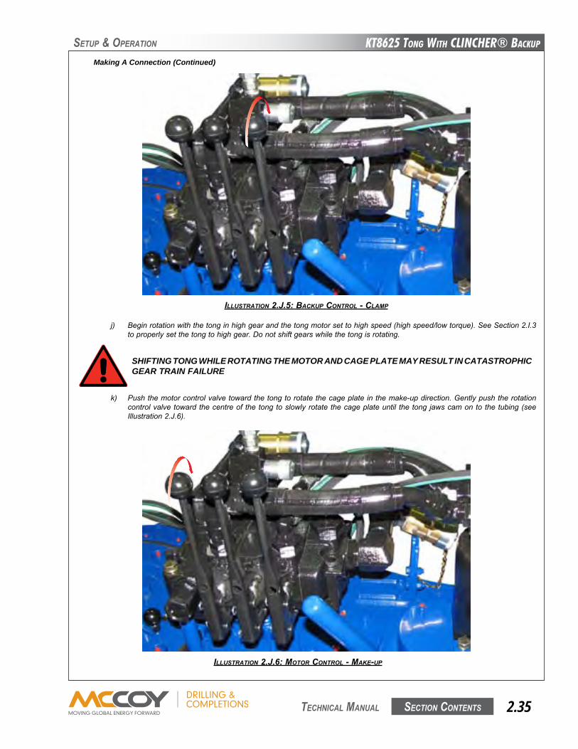
KT8625 Tong WiTh CLinChER® BaCKup
Section contentS 2.35 technical Manual
SetuP & oPeRation
j) Beginrotationwiththetonginhighgearandthetongmotorsettohighspeed(highspeed/lowtorque).SeeSection2.I.3toproperlysetthetongtohighgear.Donotshiftgearswhilethetongisrotating.
SHIFTING TONG WHILE ROTATING THE MOTOR AND CAGE PLATE MAY RESULT IN CATASTROPHIC GEAR TRAIN FAILURE
k) Pushthemotorcontrolvalvetowardthetongtorotatethecageplateinthemake-updirection.Gentlypushtherotationcontrolvalvetowardthecentreofthetongtoslowlyrotatethecageplateuntil thetongjawscamontothetubing(seeIllustration2.J.6).
ILLUSTRATION 2.J.6: MOTOR CONTROL - MAKE-Up
Making A Connection (Continued)
ILLUSTRATION 2.J.5: BACKUp CONTROL - CLAMp
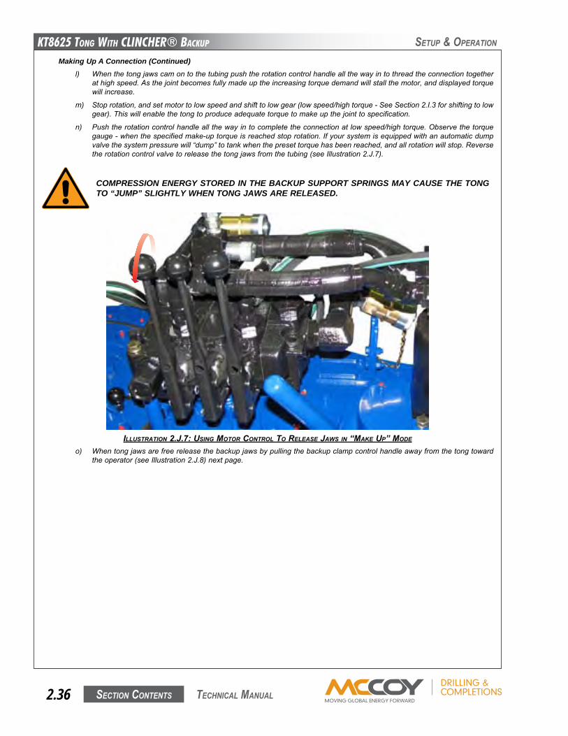
KT8625 Tong WiTh CLinChER® BaCKup
Section contentS2.36 technical Manual
SetuP & oPeRation
Making Up A Connection (Continued)l) Whenthetongjawscamontothetubingpushtherotationcontrolhandleallthewayintothreadtheconnectiontogether
athighspeed.Asthejointbecomesfullymadeuptheincreasingtorquedemandwillstallthemotor,anddisplayedtorquewillincrease.
m) Stoprotation,andsetmotortolowspeedandshifttolowgear(lowspeed/hightorque-SeeSection2.I.3forshiftingtolowgear).Thiswillenablethetongtoproduceadequatetorquetomakeupthejointtospecification.
n) Pushtherotationcontrolhandleallthewayintocompletetheconnectionatlowspeed/hightorque.Observethetorquegauge-whenthespecifiedmake-uptorqueisreachedstoprotation.Ifyoursystemisequippedwithanautomaticdumpvalvethesystempressurewill“dump”totankwhenthepresettorquehasbeenreached,andallrotationwillstop.Reversetherotationcontrolvalvetoreleasethetongjawsfromthetubing(seeIllustration2.J.7).
ILLUSTRATION 2.J.7: USINg MOTOR CONTROL TO RELEASE JAwS IN “MAKE Up” MOdE
o) Whentongjawsarefreereleasethebackupjawsbypullingthebackupclampcontrolhandleawayfromthetongtowardtheoperator(seeIllustration2.J.8)nextpage.
COMPRESSION ENERGY STORED IN THE BACKUP SUPPORT SPRINGS MAY CAUSE THE TONG TO “JUMP” SLIGHTLY WHEN TONG JAWS ARE RELEASED.
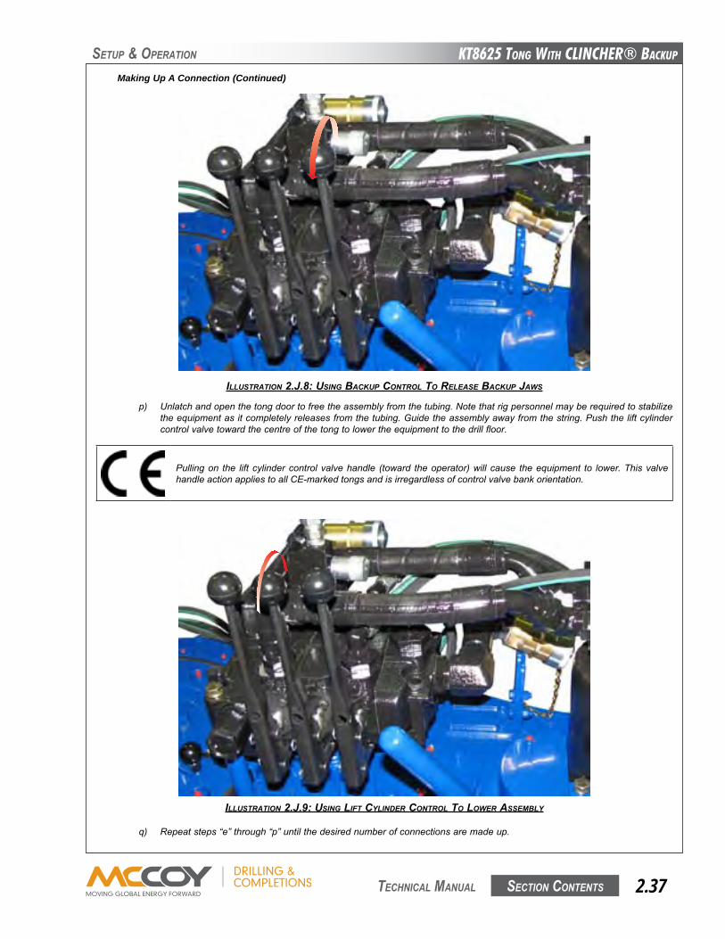
KT8625 Tong WiTh CLinChER® BaCKup
Section contentS 2.37 technical Manual
SetuP & oPeRation
ILLUSTRATION 2.J.8: USINg BACKUp CONTROL TO RELEASE BACKUp JAwS
Pullingon the liftcylindercontrolvalvehandle (toward theoperator)willcause theequipment to lower.ThisvalvehandleactionappliestoallCE-markedtongsandisirregardlessofcontrolvalvebankorientation.
Making Up A Connection (Continued)
p) Unlatchandopenthetongdoortofreetheassemblyfromthetubing.Notethatrigpersonnelmayberequiredtostabilizetheequipmentasitcompletelyreleasesfromthetubing.Guidetheassemblyawayfromthestring.Pushtheliftcylindercontrolvalvetowardthecentreofthetongtolowertheequipmenttothedrillfloor.
ILLUSTRATION 2.J.9: USINg LIFT CyLINdER CONTROL TO LOwER ASSEMBLy
q) Repeatsteps“e”through“p”untilthedesirednumberofconnectionsaremadeup.
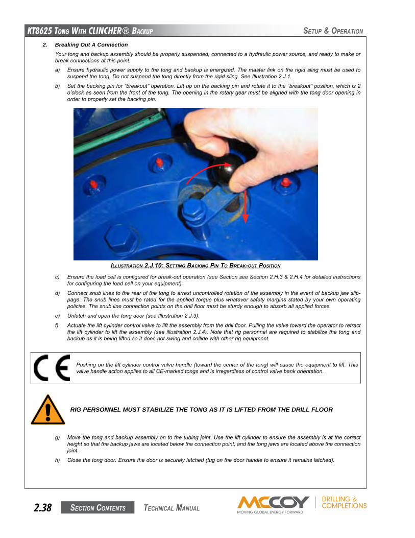
KT8625 Tong WiTh CLinChER® BaCKup
Section contentS2.38 technical Manual
SetuP & oPeRation
2. Breaking Out A ConnectionYourtongandbackupassemblyshouldbeproperlysuspended,connectedtoahydraulicpowersource,andreadytomakeorbreakconnectionsatthispoint.
a) Ensurehydraulicpowersupplytothetongandbackupisenergized.Themaster linkontherigidslingmustbeusedtosuspendthetong.Donotsuspendthetongdirectlyfromtherigidsling.SeeIllustration2.J.1.
b) Setthebackingpinfor“breakout”operation.Liftuponthebackingpinandrotateittothe“breakout”position,whichis2o’clockasseenfromthefrontofthetong.Theopeningintherotarygearmustbealignedwiththetongdooropeninginordertoproperlysetthebackingpin.
ILLUSTRATION 2.J.10: SETTINg BACKINg pIN TO BREAK-OUT pOSITION
c) Ensuretheloadcellisconfiguredforbreak-outoperation(seeSectionseeSection2.H.3&2.H.4fordetailedinstructionsforconfiguringtheloadcellonyourequipment).
d) Connectsnublinestotherearofthetongtoarrestuncontrolledrotationoftheassemblyintheeventofbackupjawslip-page.Thesnub linesmustbe rated for theapplied torquepluswhateversafetymarginsstatedbyyourownoperatingpolicies.Thesnublineconnectionpointsonthedrillfloormustbesturdyenoughtoabsorballappliedforces.
e) Unlatchandopenthetongdoor(seeIllustration2.J.3).
f) Actuatetheliftcylindercontrolvalvetolifttheassemblyfromthedrillfloor.Pullingthevalvetowardtheoperatortoretractthe liftcylinder to lift theassembly(see illustration2.J.4).Note that rigpersonnelarerequired tostabilize the tongandbackupasitisbeingliftedsoitdoesnotswingandcollidewithotherrigequipment.
RIG PERSONNEL MUST STABILIZE THE TONG AS IT IS LIFTED FROM THE DRILL FLOOR
g) Movethetongandbackupassemblyontothetubingjoint.Usetheliftcylindertoensuretheassemblyisatthecorrectheightsothatthebackupjawsarelocatedbelowtheconnectionpoint,andthetongjawsarelocatedabovetheconnectionjoint.
h) Closethetongdoor.Ensurethedoorissecurelylatched(tugonthedoorhandletoensureitremainslatched).
Pushingontheliftcylindercontrolvalvehandle(towardthecenterofthetong)willcausetheequipmenttolift.ThisvalvehandleactionappliestoallCE-markedtongsandisirregardlessofcontrolvalvebankorientation.
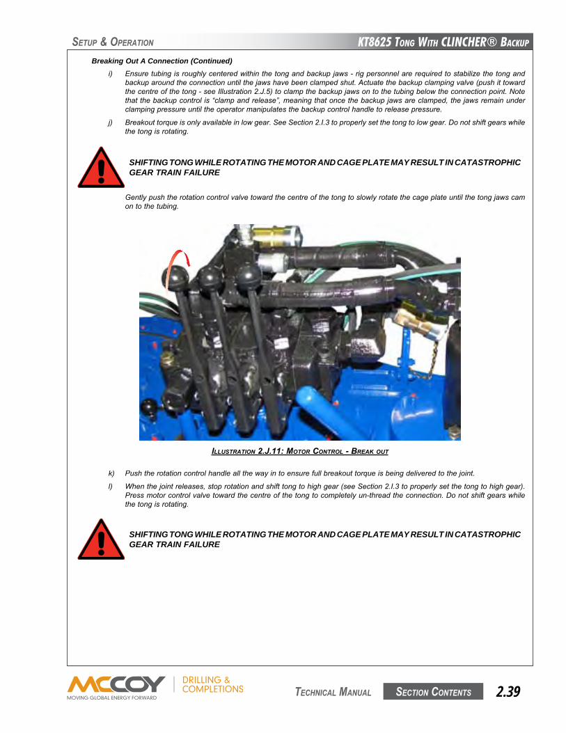
KT8625 Tong WiTh CLinChER® BaCKup
Section contentS 2.39 technical Manual
SetuP & oPeRation
Gentlypushtherotationcontrolvalvetowardthecentreofthetongtoslowlyrotatethecageplateuntilthetongjawscamontothetubing.
SHIFTING TONG WHILE ROTATING THE MOTOR AND CAGE PLATE MAY RESULT IN CATASTROPHIC GEAR TRAIN FAILURE
ILLUSTRATION 2.J.11: MOTOR CONTROL - BREAK OUT
Breaking Out A Connection (Continued)i) Ensuretubingisroughlycenteredwithinthetongandbackupjaws-rigpersonnelarerequiredtostabilizethetongand
backuparoundtheconnectionuntilthejawshavebeenclampedshut.Actuatethebackupclampingvalve(pushittowardthecentreofthetong-seeIllustration2.J.5)toclampthebackupjawsontothetubingbelowtheconnectionpoint.Notethatthebackupcontrolis“clampandrelease”,meaningthatoncethebackupjawsareclamped,thejawsremainunderclampingpressureuntiltheoperatormanipulatesthebackupcontrolhandletoreleasepressure.
j) Breakouttorqueisonlyavailableinlowgear.SeeSection2.I.3toproperlysetthetongtolowgear.Donotshiftgearswhilethetongisrotating.
k) Pushtherotationcontrolhandleallthewayintoensurefullbreakouttorqueisbeingdeliveredtothejoint.
l) Whenthejointreleases,stoprotationandshifttongtohighgear(seeSection2.I.3toproperlysetthetongtohighgear).Pressmotorcontrolvalvetowardthecentreofthetongtocompletelyun-threadtheconnection.Donotshiftgearswhilethetongisrotating.
SHIFTING TONG WHILE ROTATING THE MOTOR AND CAGE PLATE MAY RESULT IN CATASTROPHIC GEAR TRAIN FAILURE
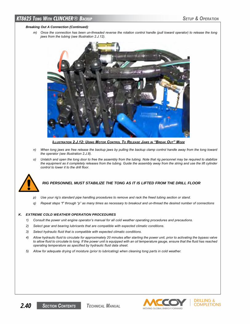
KT8625 Tong WiTh CLinChER® BaCKup
Section contentS2.40 technical Manual
SetuP & oPeRation
Breaking Out A Connection (Continued):m) Oncetheconnectionhasbeenun-threadedreversetherotationcontrolhandle(pulltowardoperator)toreleasethetong
jawsfromthetubing(seeIllustration2.J.12).
ILLUSTRATION 2.J.12: USINg MOTOR CONTROL TO RELEASE JAwS IN “BREAK OUT” MOdE
n) Whentongjawsarefreereleasethebackupjawsbypullingthebackupclampcontrolhandleawayfromthetongtowardtheoperator(seeIllustration2.J.8).
o) Unlatchandopenthetongdoortofreetheassemblyfromthetubing.Notethatrigpersonnelmayberequiredtostabilizetheequipmentasitcompletelyreleasesfromthetubing.Guidetheassemblyawayfromthestringandusetheliftcylindercontroltolowerittothedrillfloor.
p) Useyourrig’sstandardpipehandlingprocedurestoremoveandrackthefreedtubingsectionorstand.
q) Repeatsteps“f”through“p”asmanytimesasnecessarytobreakoutandun-threadthedesirednumberofconnections
K. EXTREME COLD WEATHER OPERATION PROCEDURES1) Consultthepowerunitengineoperator’smanualforallcoldweatheroperatingproceduresandprecautions.
2) Selectgearandbearinglubricantsthatarecompatiblewithexpectedclimaticconditions.
3) Selecthydraulicfluidthatiscompatiblewithexpectedclimaticconditions.
4) Allowhydraulicfluidtocirculateforapproximately20minutesafterstartingthepowerunit,priortoactivatingthebypassvalvetoallowfluidtocirculatetotong.Ifthepowerunitisequippedwithanoiltemperaturegauge,ensurethatthefluidhasreachedoperatingtemperatureasspecifiedbyhydraulicfluiddatasheet.
5) Allowforadequatedryingofmoisture(priortolubricating)whencleaningtongpartsincoldweather.
RIG PERSONNEL MUST STABILIZE THE TONG AS IT IS LIFTED FROM THE DRILL FLOOR
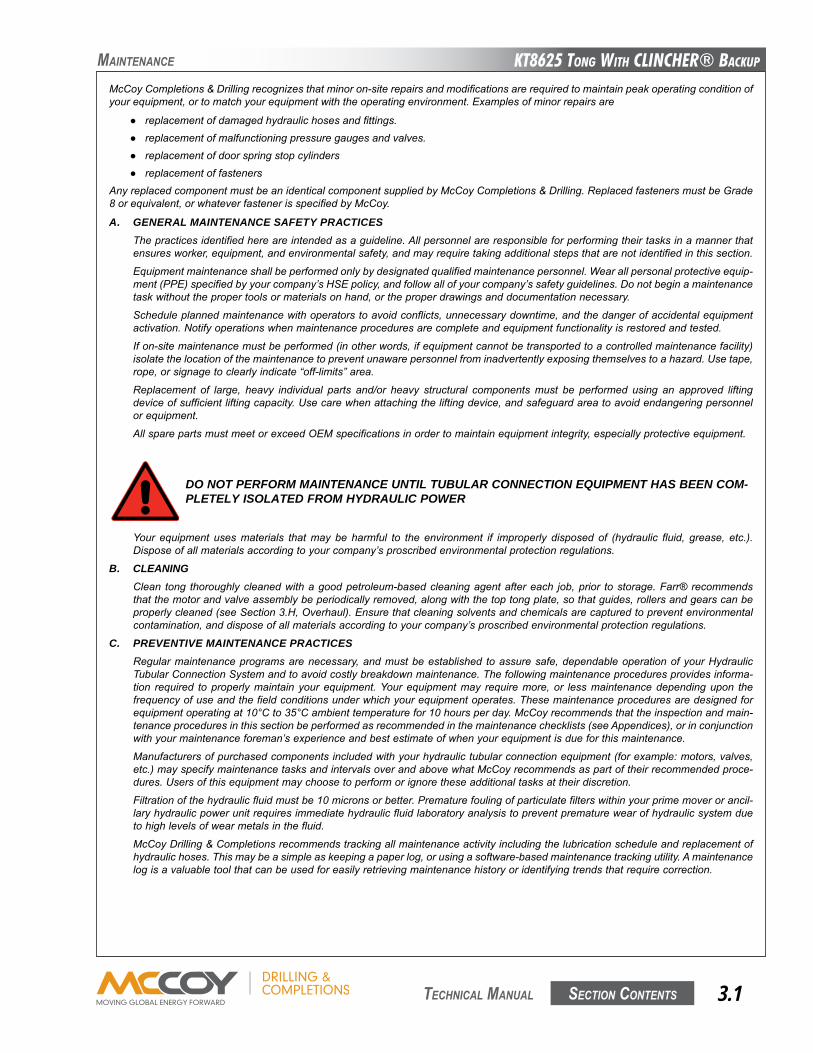
KT8625 Tong WiTh CLinChER® BaCKup
Section contentS 3.1 technical Manual
Maintenance
McCoyCompletions&Drillingrecognizesthatminoron-siterepairsandmodificationsarerequiredtomaintainpeakoperatingconditionofyourequipment,ortomatchyourequipmentwiththeoperatingenvironment.Examplesofminorrepairsare
● replacementofdamagedhydraulichosesandfittings.● replacementofmalfunctioningpressuregaugesandvalves.● replacementofdoorspringstopcylinders● replacementoffasteners
AnyreplacedcomponentmustbeanidenticalcomponentsuppliedbyMcCoyCompletions&Drilling.ReplacedfastenersmustbeGrade8orequivalent,orwhateverfastenerisspecifiedbyMcCoy.
A. GENERAL MAINTENANCE SAFETY PRACTICESThepracticesidentifiedhereareintendedasaguideline.Allpersonnelareresponsibleforperformingtheirtasksinamannerthatensuresworker,equipment,andenvironmentalsafety,andmayrequiretakingadditionalstepsthatarenotidentifiedinthissection.
Equipmentmaintenanceshallbeperformedonlybydesignatedqualifiedmaintenancepersonnel.Wearallpersonalprotectiveequip-ment(PPE)specifiedbyyourcompany’sHSEpolicy,andfollowallofyourcompany’ssafetyguidelines.Donotbeginamaintenancetaskwithoutthepropertoolsormaterialsonhand,ortheproperdrawingsanddocumentationnecessary.
Scheduleplannedmaintenancewithoperatorstoavoidconflicts,unnecessarydowntime,andthedangerofaccidentalequipmentactivation.Notifyoperationswhenmaintenanceproceduresarecompleteandequipmentfunctionalityisrestoredandtested.
Ifon-sitemaintenancemustbeperformed(inotherwords,ifequipmentcannotbetransportedtoacontrolledmaintenancefacility)isolatethelocationofthemaintenancetopreventunawarepersonnelfrominadvertentlyexposingthemselvestoahazard.Usetape,rope,orsignagetoclearlyindicate“off-limits”area.
Replacement of large, heavy individual parts and/or heavy structural componentsmust be performed using an approved liftingdeviceofsufficientliftingcapacity.Usecarewhenattachingtheliftingdevice,andsafeguardareatoavoidendangeringpersonnelorequipment.
AllsparepartsmustmeetorexceedOEMspecificationsinordertomaintainequipmentintegrity,especiallyprotectiveequipment.
DO NOT PERFORM MAINTENANCE UNTIL TUBULAR CONNECTION EQUIPMENT HAS BEEN COM-PLETELY ISOLATED FROM HYDRAULIC POWER
Your equipment usesmaterials thatmay be harmful to the environment if improperly disposed of (hydraulic fluid, grease, etc.).Disposeofallmaterialsaccordingtoyourcompany’sproscribedenvironmentalprotectionregulations.
B. CLEANINGClean tong thoroughlycleanedwithagoodpetroleum-basedcleaningagentaftereach job,prior tostorage.Farr® recommendsthatthemotorandvalveassemblybeperiodicallyremoved,alongwiththetoptongplate,sothatguides,rollersandgearscanbeproperlycleaned(seeSection3.H,Overhaul).Ensurethatcleaningsolventsandchemicalsarecapturedtopreventenvironmentalcontamination,anddisposeofallmaterialsaccordingtoyourcompany’sproscribedenvironmentalprotectionregulations.
C. PREVENTIVE MAINTENANCE PRACTICESRegularmaintenanceprogramsarenecessary,andmustbeestablished toassuresafe,dependableoperationofyourHydraulicTubularConnectionSystemandtoavoidcostlybreakdownmaintenance.Thefollowingmaintenanceproceduresprovidesinforma-tion required toproperlymaintainyourequipment.Yourequipmentmay requiremore,or lessmaintenancedependingupon thefrequencyofuseandthefieldconditionsunderwhichyourequipmentoperates.Thesemaintenanceproceduresaredesignedforequipmentoperatingat10°Cto35°Cambienttemperaturefor10hoursperday.McCoyrecommendsthattheinspectionandmain-tenanceproceduresinthissectionbeperformedasrecommendedinthemaintenancechecklists(seeAppendices),orinconjunctionwithyourmaintenanceforeman’sexperienceandbestestimateofwhenyourequipmentisdueforthismaintenance.
Manufacturersofpurchasedcomponentsincludedwithyourhydraulictubularconnectionequipment(forexample:motors,valves,etc.)mayspecifymaintenancetasksandintervalsoverandabovewhatMcCoyrecommendsaspartoftheirrecommendedproce-dures.Usersofthisequipmentmaychoosetoperformorignoretheseadditionaltasksattheirdiscretion.
Filtrationofthehydraulicfluidmustbe10micronsorbetter.Prematurefoulingofparticulatefilterswithinyourprimemoverorancil-laryhydraulicpowerunitrequiresimmediatehydraulicfluidlaboratoryanalysistopreventprematurewearofhydraulicsystemduetohighlevelsofwearmetalsinthefluid.
McCoyDrilling&Completionsrecommendstrackingallmaintenanceactivityincludingthelubricationscheduleandreplacementofhydraulichoses.Thismaybeasimpleaskeepingapaperlog,orusingasoftware-basedmaintenancetrackingutility.Amaintenancelogisavaluabletoolthatcanbeusedforeasilyretrievingmaintenancehistoryoridentifyingtrendsthatrequirecorrection.
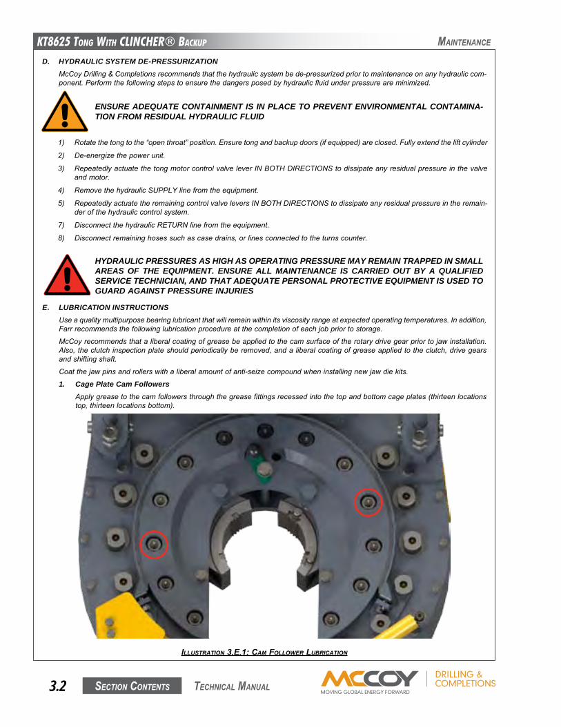
KT8625 Tong WiTh CLinChER® BaCKup
Section contentS3.2 technical Manual
Maintenance
D. HYDRAULIC SYSTEM DE-PRESSURIZATIONMcCoyDrilling&Completionsrecommendsthatthehydraulicsystembede-pressurizedpriortomaintenanceonanyhydrauliccom-ponent.Performthefollowingstepstoensurethedangersposedbyhydraulicfluidunderpressureareminimized.
HYDRAULIC PRESSURES AS HIGH AS OPERATING PRESSURE MAY REMAIN TRAPPED IN SMALL AREAS OF THE EQUIPMENT. ENSURE ALL MAINTENANCE IS CARRIED OUT BY A QUALIFIED SERVICE TECHNICIAN, AND THAT ADEQUATE PERSONAL PROTECTIVE EQUIPMENT IS USED TO GUARD AGAINST PRESSURE INJURIES
ENSURE ADEQUATE CONTAINMENT IS IN PLACE TO PREVENT ENVIRONMENTAL CONTAMINA-TION FROM RESIDUAL HYDRAULIC FLUID
1) Rotatethetongtothe“openthroat”position.Ensuretongandbackupdoors(ifequipped)areclosed.Fullyextendtheliftcylinder
2) De-energizethepowerunit.
3) RepeatedlyactuatethetongmotorcontrolvalveleverINBOTHDIRECTIONStodissipateanyresidualpressureinthevalveandmotor.
4) RemovethehydraulicSUPPLYlinefromtheequipment.
5) RepeatedlyactuatetheremainingcontrolvalveleversINBOTHDIRECTIONStodissipateanyresidualpressureintheremain-derofthehydrauliccontrolsystem.
7) DisconnectthehydraulicRETURNlinefromtheequipment.
8) Disconnectremaininghosessuchascasedrains,orlinesconnectedtotheturnscounter.
E. LUBRICATION INSTRUCTIONSUseaqualitymultipurposebearinglubricantthatwillremainwithinitsviscosityrangeatexpectedoperatingtemperatures.Inaddition,Farrrecommendsthefollowinglubricationprocedureatthecompletionofeachjobpriortostorage.
McCoyrecommendsthataliberalcoatingofgreasebeappliedtothecamsurfaceoftherotarydrivegearpriortojawinstallation.Also,theclutchinspectionplateshouldperiodicallyberemoved,andaliberalcoatingofgreaseappliedtotheclutch,drivegearsandshiftingshaft.
Coatthejawpinsandrollerswithaliberalamountofanti-seizecompoundwheninstallingnewjawdiekits.
1. Cage Plate Cam FollowersApplygreasetothecamfollowersthroughthegreasefittingsrecessedintothetopandbottomcageplates(thirteenlocationstop,thirteenlocationsbottom).
ILLUSTRATION 3.E.1: CAM FOLLOwER LUBRICATION
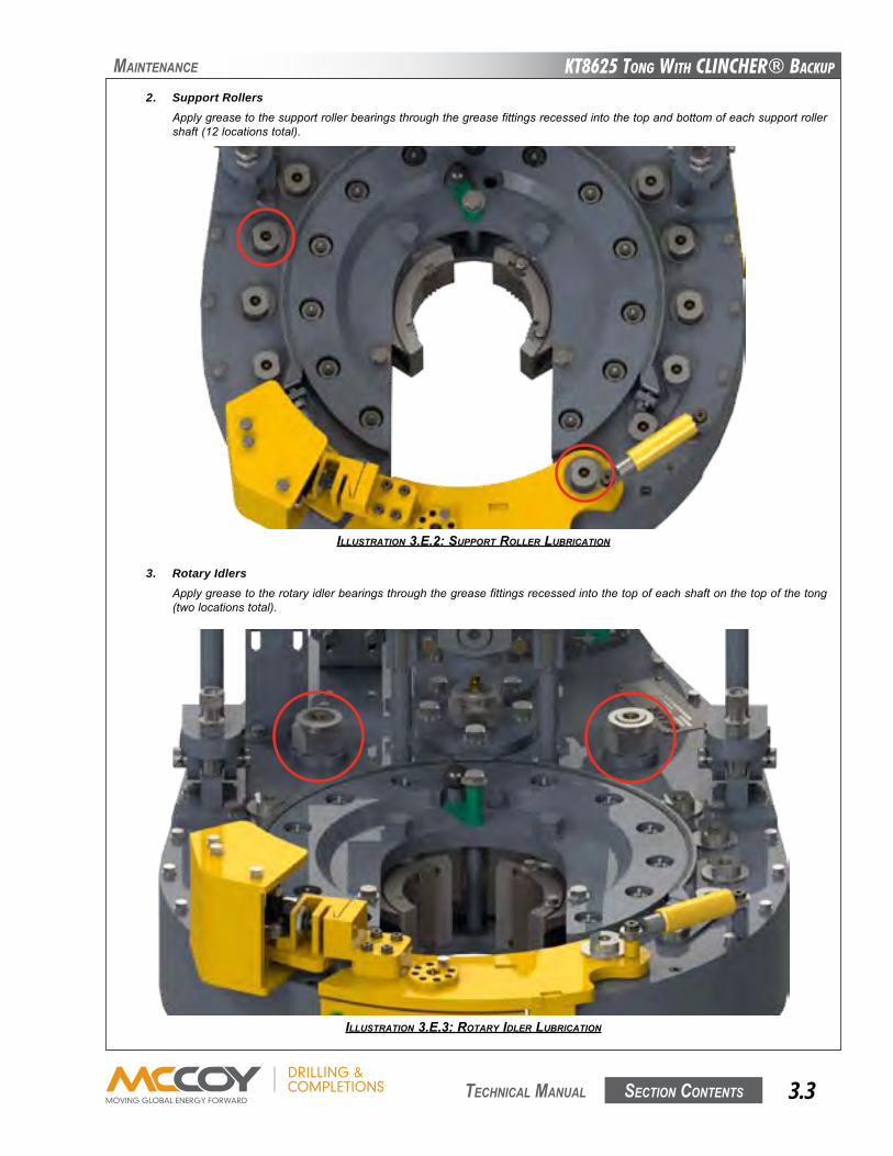
KT8625 Tong WiTh CLinChER® BaCKup
Section contentS 3.3 technical Manual
2. Support RollersApplygreasetothesupportrollerbearingsthroughthegreasefittingsrecessedintothetopandbottomofeachsupportrollershaft(12locationstotal).
ILLUSTRATION 3.E.2: SUppORT ROLLER LUBRICATION
ILLUSTRATION 3.E.3: ROTARy IdLER LUBRICATION
3. Rotary IdlersApplygreasetotherotaryidlerbearingsthroughthegreasefittingsrecessedintothetopofeachshaftonthetopofthetong(twolocationstotal).
Maintenance

KT8625 Tong WiTh CLinChER® BaCKup
Section contentS3.4 technical Manual
Maintenance
ILLUSTRATION 3.E.4: pINION IdLER LUBRICATION pOINT
4. Pinion IdlerApplygreasetothepinionidlerbearingthroughthegreasefittinglocatedonthetopfaceofthetongunderthevalvebank(onelocationonly).
5. PinionApplygreasetothepinionbearingsthroughthegreasefittingslocatedonthebearingcapsonthetopandbottomfacesofthetong(twolocationstop,twolocationsbottom).
ILLUSTRATION 3.E.5: pINION LUBRICATION pOINTS (TOp pLATE)
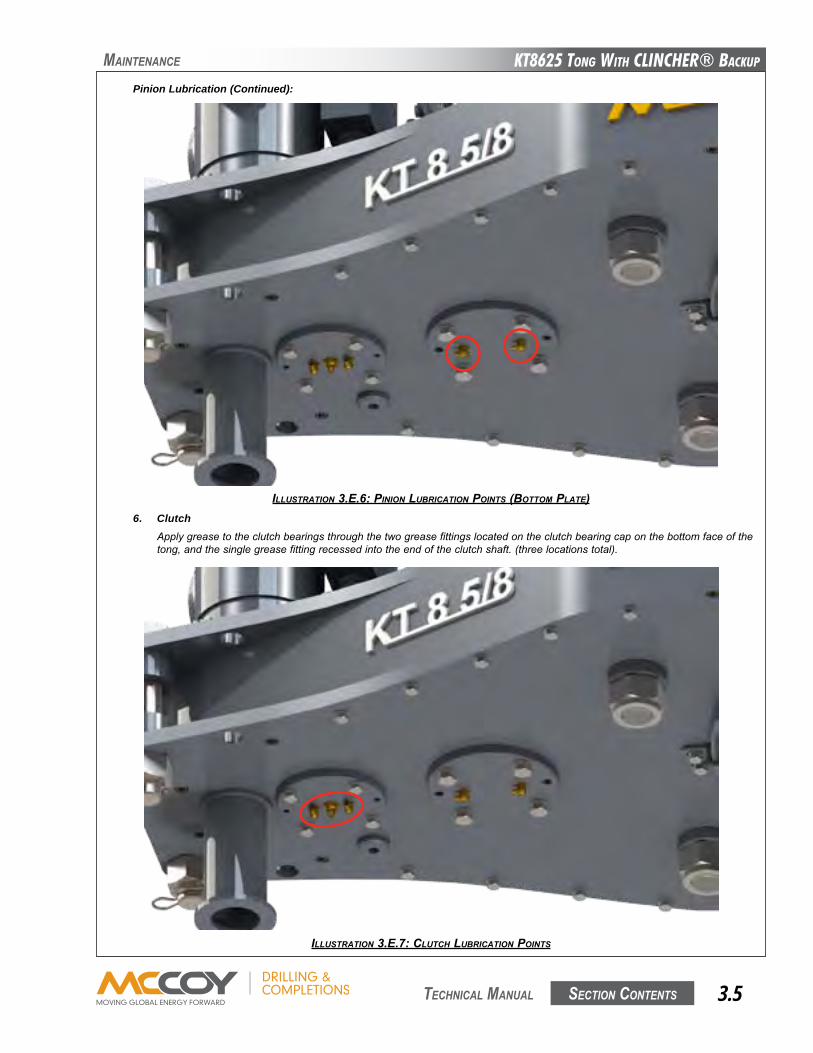
KT8625 Tong WiTh CLinChER® BaCKup
Section contentS 3.5 technical Manual
Maintenance
ILLUSTRATION 3.E.6: pINION LUBRICATION pOINTS (BOTTOM pLATE)
Pinion Lubrication (Continued):
6. ClutchApplygreasetotheclutchbearingsthroughthetwogreasefittingslocatedontheclutchbearingcaponthebottomfaceofthetong,andthesinglegreasefittingrecessedintotheendoftheclutchshaft.(threelocationstotal).
ILLUSTRATION 3.E.7: CLUTCH LUBRICATION pOINTS
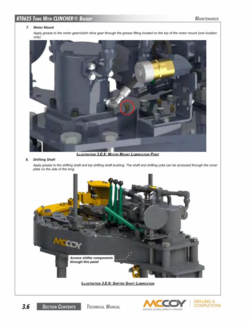
KT8625 Tong WiTh CLinChER® BaCKup
Section contentS3.6 technical Manual
Maintenance
7. Motor MountApplygreasetothemotorgear/clutchdrivegearthroughthegreasefittinglocatedonthetopofthemotormount(onelocationonly).
ILLUSTRATION 3.E.8: MOTOR MOUNT LUBRICATION pOINT
ILLUSTRATION 3.E.9: SHIFTER SHAFT LUBRICATION
8. Shifting ShaftApplygreasetotheshiftingshaftandtopshiftingshaftbushing.Theshaftandshiftingyokecanbeaccessedthroughthecoverplateonthesideofthetong.
Access shifter components through this panel
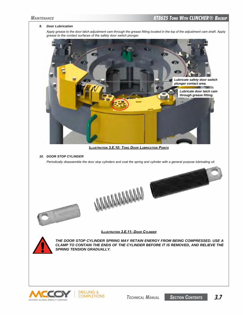
KT8625 Tong WiTh CLinChER® BaCKup
Section contentS 3.7 technical Manual
Maintenance
9. Door LubricationApplygreasetothedoorlatchadjustmentcamthroughthegreasefittinglocatedinthetopoftheadjustmentcamshaft.Applygreasetothecontactsurfacesofthesafetydoorswitchplunger.
ILLUSTRATION 3.E.10: TONg dOOR LUBRICATION pOINTS
10. DOOR STOP CYLINDER Periodicallydisassemblethedoorstopcylindersandcoatthespringandcylinderwithageneralpurposelubricatingoil.
ILLUSTRATION 3.E.11: dOOR CyLINdER
THE DOOR STOP CYLINDER SPRING MAY RETAIN ENERGY FROM BEING COMPRESSED. USE A CLAMP TO CONTAIN THE ENDS OF THE CYLINDER BEFORE IT IS REMOVED, AND RELIEVE THE SPRING TENSION GRADUALLY.
Lubricate safety door switch plunger contact area.
Lubricate door latch cam through grease fitting.
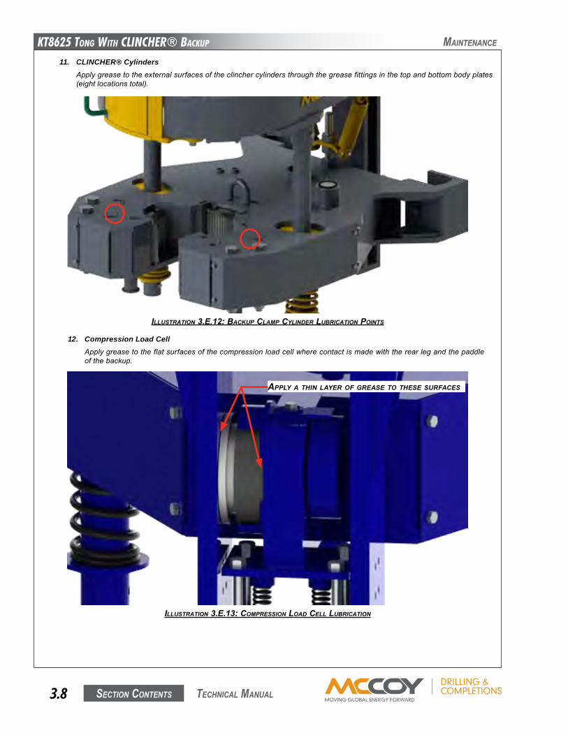
KT8625 Tong WiTh CLinChER® BaCKup
Section contentS3.8 technical Manual
11. CLINCHER® Cylinders Applygreasetotheexternalsurfacesoftheclinchercylindersthroughthegreasefittingsinthetopandbottombodyplates(eightlocationstotal).
ILLUSTRATION 3.E.12: BACKUp CLAMp CyLINdER LUBRICATION pOINTS
12. Compression Load Cell Applygreasetotheflatsurfacesofthecompressionloadcellwherecontactismadewiththerearlegandthepaddleofthebackup.
ILLUSTRATION 3.E.13: COMpRESSION LOAd CELL LUBRICATION
Maintenance
AppLy A THIN LAyER OF gREASE TO THESE SURFACES
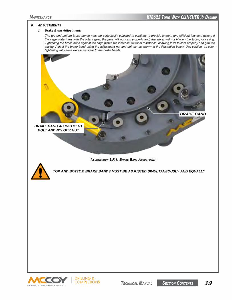
KT8625 Tong WiTh CLinChER® BaCKup
Section contentS 3.9 technical Manual
Maintenance
F. ADJUSTMENTS1. Brake Band Adjustment:
Thetopandbottombrakebandsmustbeperiodicallyadjustedtocontinuetoprovidesmoothandefficientjawcamaction.Ifthecageplateturnswiththerotarygear, the jawswillnotcamproperlyand, therefore,willnotbiteonthetubingorcasing.Tighteningthebrakebandagainstthecageplateswillincreasefrictionalresistance,allowingjawstocamproperlyandgripthecasing.Adjustthebrakebandusingtheadjustmentnutandboltsetasshownintheillustrationbelow.Usecaution,asover-tighteningwillcauseexcessiveweartothebrakebands.
ILLUSTRATION 3.F.1: BRAKE BANd AdJUSTMENT
TOP AND BOTTOM BRAKE BANDS MUST BE ADJUSTED SIMULTANEOUSLY AND EQUALLY
BRAKE BAND
BRAKE BAND ADJUSTMENT BOLT AND NYLOCK NUT
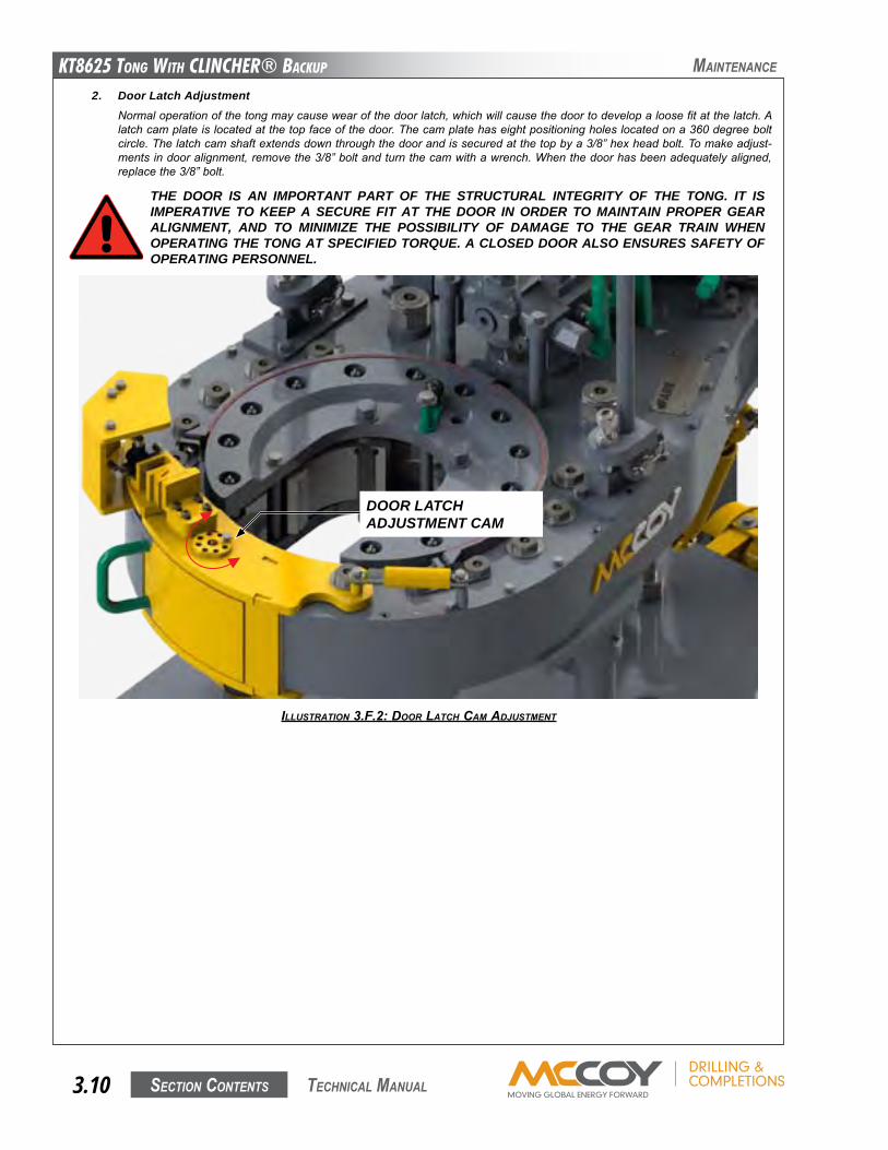
KT8625 Tong WiTh CLinChER® BaCKup
Section contentS3.10 technical Manual
Maintenance
2. Door Latch AdjustmentNormaloperationofthetongmaycausewearofthedoorlatch,whichwillcausethedoortodevelopaloosefitatthelatch.Alatchcamplateislocatedatthetopfaceofthedoor.Thecamplatehaseightpositioningholeslocatedona360degreeboltcircle.Thelatchcamshaftextendsdownthroughthedoorandissecuredatthetopbya3/8”hexheadbolt.Tomakeadjust-mentsindooralignment,removethe3/8”boltandturnthecamwithawrench.Whenthedoorhasbeenadequatelyaligned,replacethe3/8”bolt.
THE DOOR IS AN IMPORTANT PART OF THE STRUCTURAL INTEGRITY OF THE TONG. IT IS IMPERATIVE TO KEEP A SECURE FIT AT THE DOOR IN ORDER TO MAINTAIN PROPER GEAR ALIGNMENT, AND TO MINIMIZE THE POSSIBILITY OF DAMAGE TO THE GEAR TRAIN WHEN OPERATING THE TONG AT SPECIFIED TORQUE. A CLOSED DOOR ALSO ENSURES SAFETY OF OPERATING PERSONNEL.
ILLUSTRATION 3.F.2: dOOR LATCH CAM AdJUSTMENT
DOOR LATCHADJUSTMENT CAM
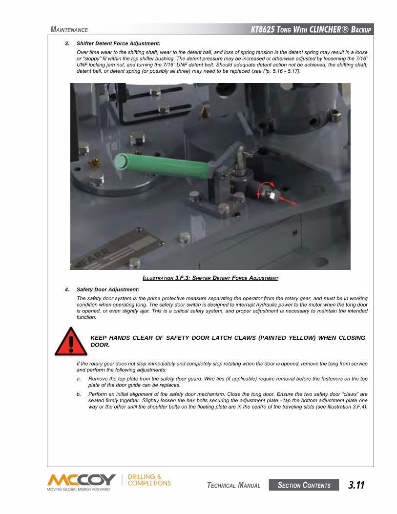
KT8625 Tong WiTh CLinChER® BaCKup
Section contentS 3.11 technical Manual
Maintenance
3. Shifter Detent Force Adjustment:Overtimeweartotheshiftingshaft,weartothedetentball,andlossofspringtensioninthedetentspringmayresultinalooseor“sloppy”fitwithinthetopshifterbushing.Thedetentpressuremaybeincreasedorotherwiseadjustedbylooseningthe7/16”UNFlockingjamnut,andturningthe7/16”UNFdetentbolt.Shouldadequatedetentactionnotbeachieved,theshiftingshaft,detentball,ordetentspring(orpossiblyallthree)mayneedtobereplaced(seePp.5.16-5.17).
ILLUSTRATION 3.F.3: SHIFTER dETENT FORCE AdJUSTMENT
4. Safety Door Adjustment:Thesafetydoorsystemistheprimeprotectivemeasureseparatingtheoperatorfromtherotarygear,andmustbeinworkingconditionwhenoperatingtong.Thesafetydoorswitchisdesignedtointerrupthydraulicpowertothemotorwhenthetongdoorisopened,orevenslightlyajar.Thisisacriticalsafetysystem,andproperadjustmentisnecessarytomaintaintheintendedfunction.
KEEP HANDS CLEAR OF SAFETY DOOR LATCH CLAWS (PAINTED YELLOW) WHEN CLOSING DOOR.
Iftherotarygeardoesnotstopimmediatelyandcompletelystoprotatingwhenthedoorisopened,removethetongfromserviceandperformthefollowingadjustments:
a. Removethetopplatefromthesafetydoorguard.Wireties(ifapplicable)requireremovalbeforethefastenersonthetopplateofthedoorguidecanbereplaces.
b. Performaninitialalignmentofthesafetydoormechanism.Closethetongdoor.Ensurethetwosafetydoor“claws”areseatedfirmlytogether.Slightlyloosenthehexboltssecuringtheadjustmentplate-tapthebottomadjustmentplateonewayortheotheruntiltheshoulderboltsonthefloatingplateareinthecentreofthetravelingslots(seeIllustration3.F.4).
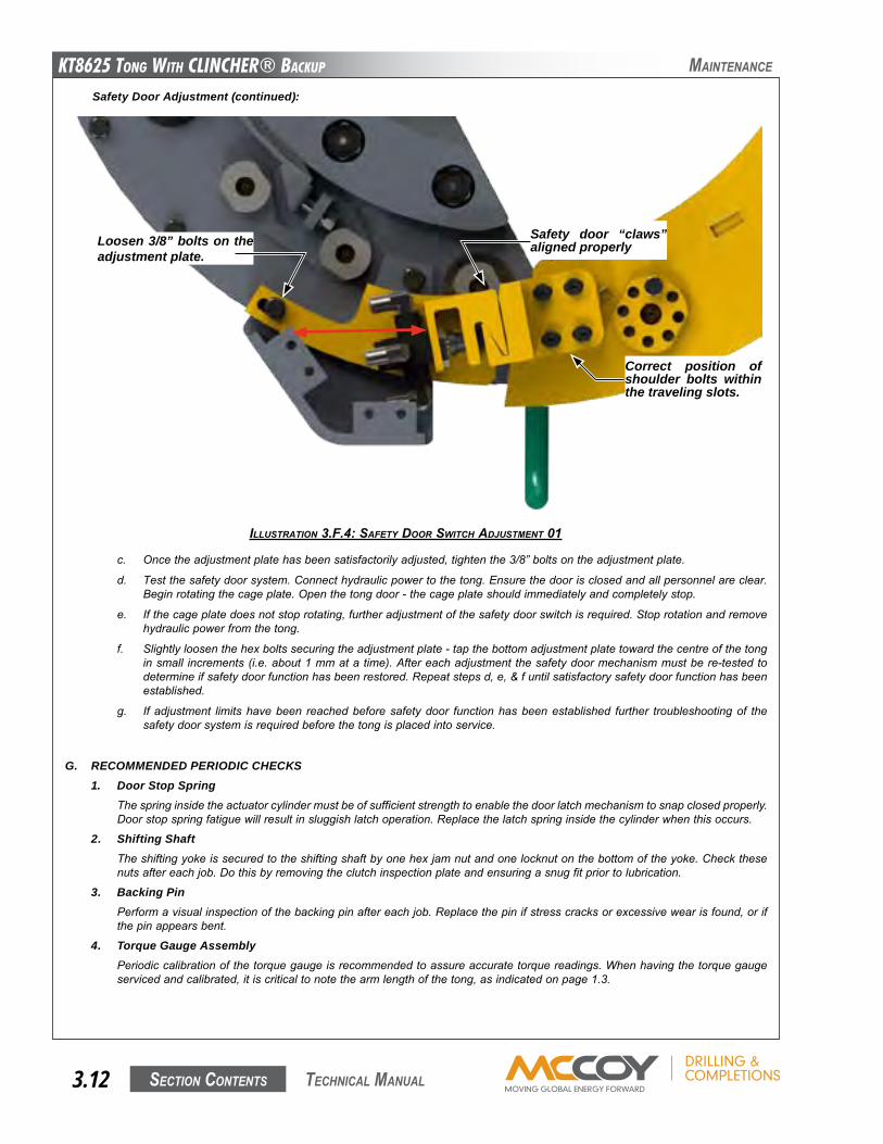
KT8625 Tong WiTh CLinChER® BaCKup
Section contentS3.12 technical Manual
ILLUSTRATION 3.F.4: SAFETy dOOR SwITCH AdJUSTMENT 01
c. Oncetheadjustmentplatehasbeensatisfactorilyadjusted,tightenthe3/8”boltsontheadjustmentplate.
d. Testthesafetydoorsystem.Connecthydraulicpowertothetong.Ensurethedoorisclosedandallpersonnelareclear.Beginrotatingthecageplate.Openthetongdoor-thecageplateshouldimmediatelyandcompletelystop.
e. Ifthecageplatedoesnotstoprotating,furtheradjustmentofthesafetydoorswitchisrequired.Stoprotationandremovehydraulicpowerfromthetong.
f. Slightlyloosenthehexboltssecuringtheadjustmentplate-tapthebottomadjustmentplatetowardthecentreofthetonginsmall increments(i.e.about1mmatatime).Aftereachadjustmentthesafetydoormechanismmustbere-testedtodetermineifsafetydoorfunctionhasbeenrestored.Repeatstepsd,e,&funtilsatisfactorysafetydoorfunctionhasbeenestablished.
g. Ifadjustment limitshavebeen reachedbeforesafetydoor functionhasbeenestablished further troubleshootingof thesafetydoorsystemisrequiredbeforethetongisplacedintoservice.
G. RECOMMENDED PERIODIC CHECKS1. Door Stop Spring
Thespringinsidetheactuatorcylindermustbeofsufficientstrengthtoenablethedoorlatchmechanismtosnapclosedproperly.Doorstopspringfatiguewillresultinsluggishlatchoperation.Replacethelatchspringinsidethecylinderwhenthisoccurs.
2. Shifting ShaftTheshiftingyokeissecuredtotheshiftingshaftbyonehexjamnutandonelocknutonthebottomoftheyoke.Checkthesenutsaftereachjob.Dothisbyremovingtheclutchinspectionplateandensuringasnugfitpriortolubrication.
3. Backing PinPerformavisualinspectionofthebackingpinaftereachjob.Replacethepinifstresscracksorexcessivewearisfound,orifthepinappearsbent.
4. Torque Gauge AssemblyPeriodiccalibrationofthetorquegaugeisrecommendedtoassureaccuratetorquereadings.Whenhavingthetorquegaugeservicedandcalibrated,itiscriticaltonotethearmlengthofthetong,asindicatedonpage1.3.
Safety Door Adjustment (continued):
Maintenance
Correct position of shoulder bolts within the traveling slots.
Loosen 3/8” bolts on the adjustment plate.
Safety door “claws” aligned properly
KT8625 Tong WiTh CLinChER® BaCKup
Section contentS 3.13 technical Manual
Maintenance
ALL MAINTENANCE AND OVERHAUL SHOULD BE PERFORMED FROM THE TOP. THE BOTTOM PLATE OF THE TONG IS TYPICALLY WELDED TO THE SIDE BODY AND CANNOT BE REMOVED.
REPLACEMENT FASTENERS (BOLTS, NUTS, CAP SCREWS, MACHINE SCREWS, ETC.) USED DURING MAINTENANCE OR OVERHAUL MUST BE GRADE 8 OR EQUIVALENT.FASTENERS USED FOR MAINTENANCE OR OVERHAUL OF LOAD-BEARING COMPONENTS (CHAIN SLINGS, RIGID SLINGS, LEGS) MUST BE TIGHTENED TO THE PROPER TORQUE
H. OVERHAUL PROCEDURES - DISASSEMBLYSeparatethetongandbackupusingthedisassemblyinstructionsspecifiedinthefollowingprocedure.Followingseparationofthetongandbackupthegeartrainisaccessedbyremovingthetopplateofthetong.
SEPARATION OF TONG FROM BACKUP1. Suspendtongassemblywithcrane.Constructasupportstructurethatwillsupporttheweightofthebackup.Lowerthetong/
backupassemblyontotheconstructedsupportuntilallweightisremovedfromfrontlegsuspensionsprings.
2. Removethe7/16”nutandboltsetsfromthebottomofthefrontlegs,andslidethelowerspringcapsandfrontlegcoilspringsoffeachleg.Notethatthetopspringcapswillremainwithinthebackupbodyassembly.
3. Disconnectthetworearbackupsupportspringsconnectingthebackuptotherearleg.
4. Removetheloadcellassembly.
5. Lifttongandlegsupandawayfromthebackup,andsettongontoaflatworksurfacethatwillsupporttheweightofthetong,andallowaccesstothebottomplate-ensurethatthelegsdonothaveanyweightonthem.
REMOVAL OF LEG ASSEMBLIES.6. Removetherearlegassemblybyremovingtwo1-1/4”x9”hexboltandnutsetsandtwo1”x8”hexboltandnutsets.
7. Removethefrontlegassembliesbyremovingthe7/16”x3”boltsandnutsetoneachleg,andslidelegtubesoutoflegmountweldments.
REMOVAL OF TOP PLATE8. Removetherigidslingassemblybydisconnectingthelevelingdevicesfromthehangerbrackets.
9. Removethetworigidslinghangerbrackets.
10. Disconnectthethreehydraulicconnectionsfromthemotor.Undotherestraintssecuringtheinletandoutletlinesconnectionstotheirsupports.
11. Supportthehydraulicvalveassemblywithatemporary liftingslingandacrane.Removethe1/2”x4-1/2”boltssecuringthehydraulicvalveassemblytothevalvesupportposts.Liftthehydraulicvalvesectionupandawayfromthetopplateofthetong.Ifthehydraulicvalveassemblydoesnotrequireserviceensureitisstoredinaclean,securelocation.Coverallexposedcon-nections.DISASSEMBLY NOTE (CE MARKED TONGS ONLY):Thevalvehandleguarddoesnotneedtoberemovedfromthevalvebank.Donotliftthevalveassemblyusingtheprotectivehandle.
12. Removetheinletandoutletsupportpieces.
13. Removetopbrakebandassembly(leaveadjustmentlugweldmentsinplacefornow).
14. Removethetongdoorstopcylinder.Thedoorstopcylinderspringmayretainenergyfrombeingcompressed.Useaclamptocontaintheendsofthecylinderwhenitisremoved,andrelievethespringtensiongradually.
15. Removedoorassemblybyremovingthedoorrollershaft.Supportdoorassemblyastherollershaftisremoved.Removethenutfromthetopoftherollershaft,anduseasoftalloymaterial(e.g.brassrod,etc.)tolightlytaptheshaftdownthroughthesupportrollerassemblyuntilitcomesfreeatthebottom.Usecautionthatthethreadsontheendsofthesupportrollershaftsarenotdamaged.Donotlosethedoorshoulderbushings.
16. Removethehitchpinsecuringthetorquegaugeholdertothetorquegaugemountweldment,andremovethemount.
17. Removethefourhexsocketheadcapscrewssecuringthemotorandthetorquegaugemountweldment.Removethetorquegaugemountweldment,thenliftthemotorupandawayfromthemotormount.Inspectthemotorgear,locatedatthebottomofthemotorshaft,forgearclashingortoothdamage.Also,ensurethatthemotorgearissecurelyattachedtothemotorshaft.
18. Removethecotterpinandclevispinconnectingtheshifterhandletotheshiftershaft(itisnotnecessarytodisconnectthehandlefromthepivotlugweldment).
Theheadsofthefastenerssecuringtherigidslinghangerbracketsaredrilled,andareconstrainedtothebracketsusingwireties.Wiretiesmustberemovedbeforeextractingthefastenersandremovingtherigidslinghangerbracket.
KT8625 Tong WiTh CLinChER® BaCKup
Section contentS3.14 technical Manual
IF THE BEARING REMAINS ATTACHED TO THE GEAR SHAFT AFTER THE BEARING CAP IS PULLED, FARR SERVICE PERSONNEL RECOMMENDS LEAVING IT IN PLACE UNTIL THE TOP TONG PLATE IS REMOVED.
26. Removethejawpivotboltsandthejawassemblies.
27. Ensure thebottomcageplate is supportedbeforebeginning this step.Remove the two front cageplatebolt andnut sets.Removethebackingpinassemblyandtherearcageplatebolt,andthecageplatespacers.Thetopandbottomcageplatesmaynowberemoved-Notethatthecamfollowersarefastenedtothetopandbottomcageplates,sousecautionnottodam-agethem.
Maintenance
28. Removethetopnutsandpadsfortherotaryidlergears.
29. Removetheremainingtoprollershaftnuts.Notethatthetopbrakebandadjustmentlugweldmentsareremovedatthispoint.
30. Loosen,butdonotremovethedetentboltonthetopshifterlugweldment.Oncetheforcefromthedetentballhasbeenremovedfromtheshiftershaft,thetopshifterbushingcanbeun-threadedfromthetopplate.Takecarenottolosethedetentballwhenthebushingcomesfreeoftheshaft.
31. Removethehexheadboltsandhexflatheadcapscrewsaroundtheperimeterofthetongthatsecurethetopplate.
22. Withalltheabovestepstaken,thetoptongplatecanbeliftedoffprovidingaccesstotheinsideofthegearcase.
THE CAGE PLATE BOLTS ARE THE ONLY ITEMS FASTENING THE BOTTOM CAGE PLATE TO THE TONG. SUPPORT THE BOTTOM CAGE PLATE FROM BELOW PRIOR TO REMOVING CAGE PLATE BOLTS IN ORDER TO PREVENT DAMAGE TO THE BOTTOM CAGE PLATE OR PERSONAL INJURY TO THE MECHANIC
Removal of Top Plate (Continued):
19. Unboltthepivotlugweldmentfromthetopplate,andremovethepivotlugandhandleassembly.
20. Removethefourhexsocketheadcapscrewssecuringthemotormounttothetopplate.Usecarenottodislodgeandlosethetwopositioningdowels.
21. Removethesnapringsecuringthedrivegeartothetopoftheclutchshaft.Carefullyremovethedrivegearfromtheclutchshaft.
22. Removethetwo10-24x3/4”hexsocketheadcapscrewssecuringthetopclutchbearingretainertothetopplate.
23. Removethetopclutchbearingretainer,andbearingretainerspacer.Thetopclutchbearingandclutchbearingbushingmaycomeoffwiththebearingretainer.
24. Removethe1-1/4”nylocknutandthethree5/8”boltssecuringthepinionidlerhalf-moonpad.
25. Pullthetoppiniongearbearingcapbyremovingthefour1/2”boltswhichsecurethebearingcap.Threadtwooftheremovedboltsintotheextraholesontopofthebearingcap,andusethemasliftinglugstoliftthebearingcapoutofplace.
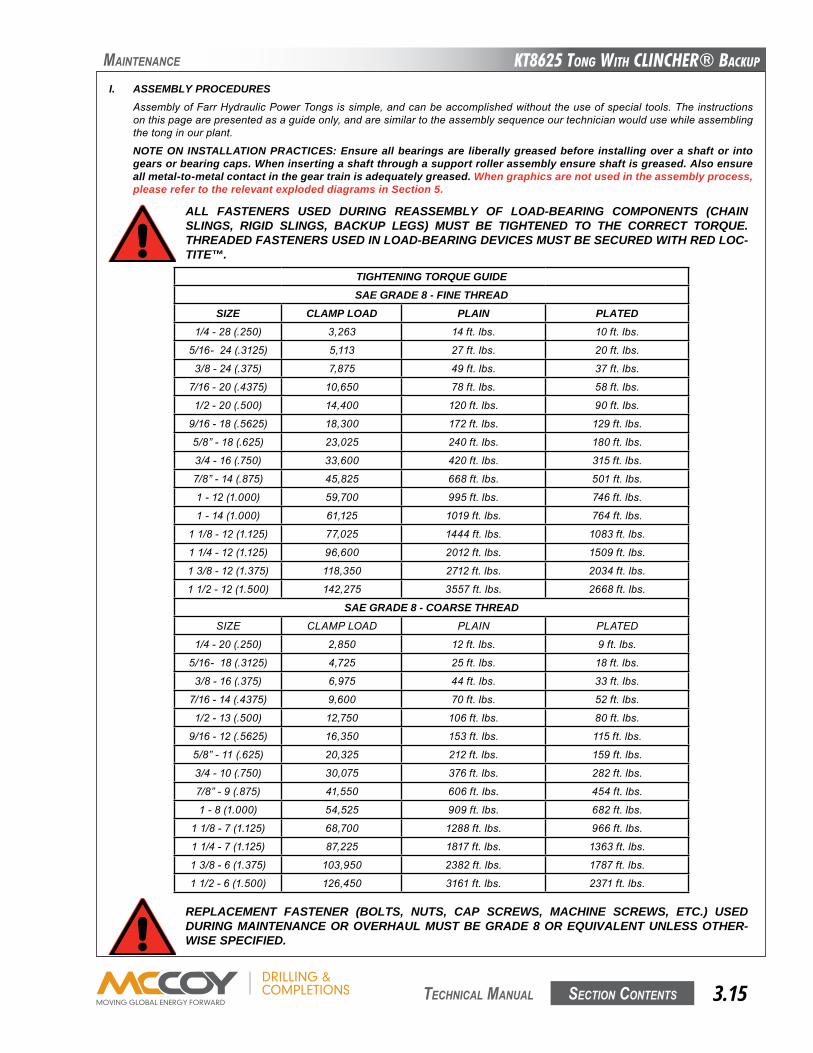
KT8625 Tong WiTh CLinChER® BaCKup
Section contentS 3.15 technical Manual
Maintenance
ALL FASTENERS USED DURING REASSEMBLY OF LOAD-BEARING COMPONENTS (CHAIN SLINGS, RIGID SLINGS, BACKUP LEGS) MUST BE TIGHTENED TO THE CORRECT TORQUE. THREADED FASTENERS USED IN LOAD-BEARING DEVICES MUST BE SECURED WITH RED LOC-TITE™.
I. ASSEMBLY PROCEDURESAssemblyofFarrHydraulicPowerTongsissimple,andcanbeaccomplishedwithouttheuseofspecialtools.Theinstructionsonthispagearepresentedasaguideonly,andaresimilartotheassemblysequenceourtechnicianwouldusewhileassemblingthetonginourplant.
NOTE ON INSTALLATION PRACTICES: Ensure all bearings are liberally greased before installing over a shaft or into gears or bearing caps. When inserting a shaft through a support roller assembly ensure shaft is greased. Also ensure all metal-to-metal contact in the gear train is adequately greased. When graphics are not used in the assembly process, please refer to the relevant exploded diagrams in Section 5.
TIGHTENING TORQUE GUIDESAE GRADE 8 - FINE THREAD
SIZE CLAMP LOAD PLAIN PLATED1/4-28(.250) 3,263 14ft.lbs. 10ft.lbs.
5/16-24(.3125) 5,113 27ft.lbs. 20ft.lbs.
3/8-24(.375) 7,875 49ft.lbs. 37ft.lbs.
7/16-20(.4375) 10,650 78ft.lbs. 58ft.lbs.
1/2-20(.500) 14,400 120ft.lbs. 90ft.lbs.
9/16-18(.5625) 18,300 172ft.lbs. 129ft.lbs.
5/8”-18(.625) 23,025 240ft.lbs. 180ft.lbs.
3/4-16(.750) 33,600 420ft.lbs. 315ft.lbs.
7/8”-14(.875) 45,825 668ft.lbs. 501ft.lbs.
1-12(1.000) 59,700 995ft.lbs. 746ft.lbs.
1-14(1.000) 61,125 1019ft.lbs. 764ft.lbs.
11/8-12(1.125) 77,025 1444ft.lbs. 1083ft.lbs.
11/4-12(1.125) 96,600 2012ft.lbs. 1509ft.lbs.
13/8-12(1.375) 118,350 2712ft.lbs. 2034ft.lbs.
11/2-12(1.500) 142,275 3557ft.lbs. 2668ft.lbs.
SAE GRADE 8 - COARSE THREADSIzE CLAMPLOAD PLAIN PLATED
1/4-20(.250) 2,850 12ft.lbs. 9ft.lbs.
5/16-18(.3125) 4,725 25ft.lbs. 18ft.lbs.
3/8-16(.375) 6,975 44ft.lbs. 33ft.lbs.
7/16-14(.4375) 9,600 70ft.lbs. 52ft.lbs.
1/2-13(.500) 12,750 106ft.lbs. 80ft.lbs.
9/16-12(.5625) 16,350 153ft.lbs. 115ft.lbs.
5/8”-11(.625) 20,325 212ft.lbs. 159ft.lbs.
3/4-10(.750) 30,075 376ft.lbs. 282ft.lbs.
7/8”-9(.875) 41,550 606ft.lbs. 454ft.lbs.
1-8(1.000) 54,525 909ft.lbs. 682ft.lbs.
11/8-7(1.125) 68,700 1288ft.lbs. 966ft.lbs.
11/4-7(1.125) 87,225 1817ft.lbs. 1363ft.lbs.
13/8-6(1.375) 103,950 2382ft.lbs. 1787ft.lbs.
11/2-6(1.500) 126,450 3161ft.lbs. 2371ft.lbs.
REPLACEMENT FASTENER (BOLTS, NUTS, CAP SCREWS, MACHINE SCREWS, ETC.) USED DURING MAINTENANCE OR OVERHAUL MUST BE GRADE 8 OR EQUIVALENT UNLESS OTHER-WISE SPECIFIED.
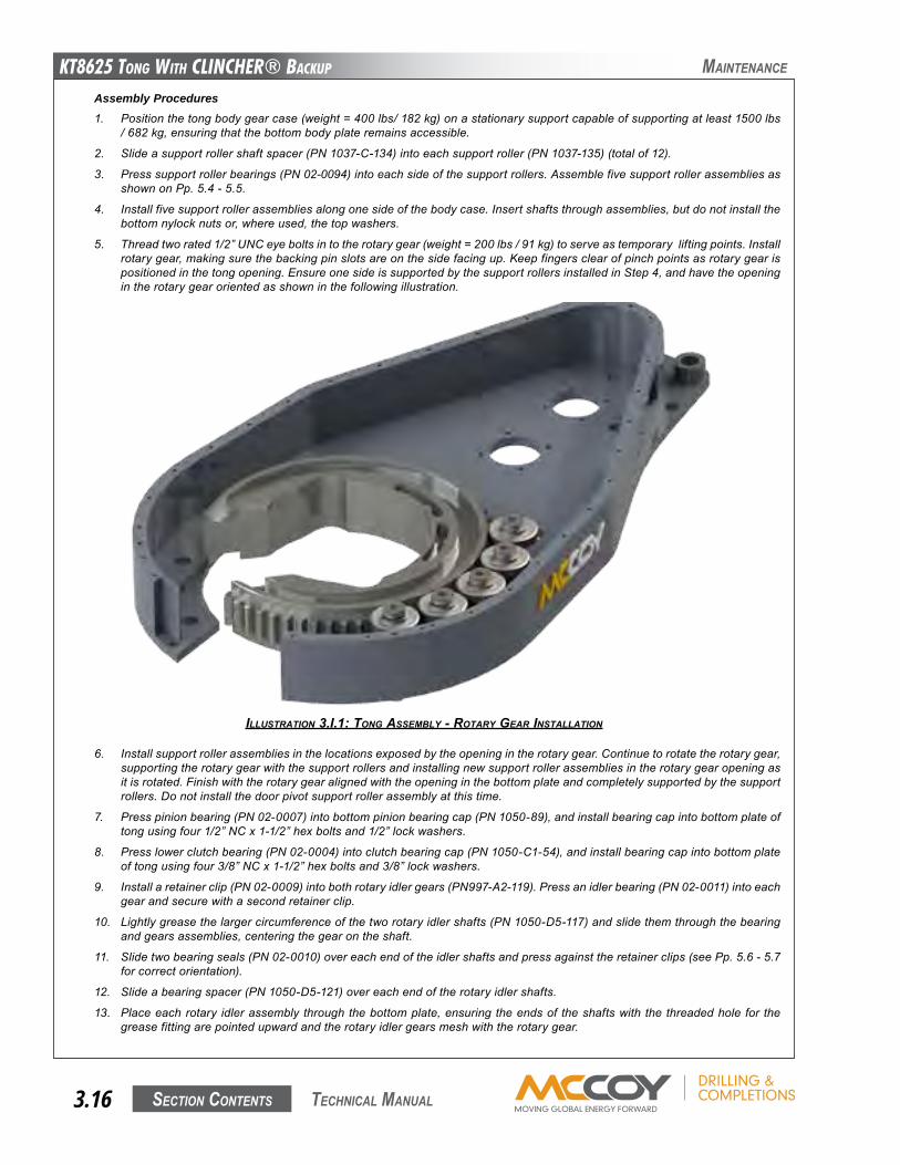
KT8625 Tong WiTh CLinChER® BaCKup
Section contentS3.16 technical Manual
Assembly Procedures1. Positionthetongbodygearcase(weight=400lbs/182kg)onastationarysupportcapableofsupportingatleast1500lbs
/682kg,ensuringthatthebottombodyplateremainsaccessible.
2. Slideasupportrollershaftspacer(PN1037-C-134)intoeachsupportroller(PN1037-135)(totalof12).
3. Presssupportrollerbearings(PN02-0094)intoeachsideofthesupportrollers.AssemblefivesupportrollerassembliesasshownonPp.5.4-5.5.
4. Installfivesupportrollerassembliesalongonesideofthebodycase.Insertshaftsthroughassemblies,butdonotinstallthebottomnylocknutsor,whereused,thetopwashers.
5. Threadtworated1/2”UNCeyeboltsintotherotarygear(weight=200lbs/91kg)toserveastemporaryliftingpoints.Installrotarygear,makingsurethebackingpinslotsareonthesidefacingup.Keepfingersclearofpinchpointsasrotarygearispositionedinthetongopening.EnsureonesideissupportedbythesupportrollersinstalledinStep4,andhavetheopeningintherotarygearorientedasshowninthefollowingillustration.
ILLUSTRATION 3.I.1: TONg ASSEMBLy - ROTARy gEAR INSTALLATION
Maintenance
6. Installsupportrollerassembliesinthelocationsexposedbytheopeningintherotarygear.Continuetorotatetherotarygear,supportingtherotarygearwiththesupportrollersandinstallingnewsupportrollerassembliesintherotarygearopeningasitisrotated.Finishwiththerotarygearalignedwiththeopeninginthebottomplateandcompletelysupportedbythesupportrollers.Donotinstallthedoorpivotsupportrollerassemblyatthistime.
7. Presspinionbearing(PN02-0007)intobottompinionbearingcap(PN1050-89),andinstallbearingcapintobottomplateoftongusingfour1/2”NCx1-1/2”hexboltsand1/2”lockwashers.
8. Presslowerclutchbearing(PN02-0004)intoclutchbearingcap(PN1050-C1-54),andinstallbearingcapintobottomplateoftongusingfour3/8”NCx1-1/2”hexboltsand3/8”lockwashers.
9. Installaretainerclip(PN02-0009)intobothrotaryidlergears(PN997-A2-119).Pressanidlerbearing(PN02-0011)intoeachgearandsecurewithasecondretainerclip.
10. Lightlygreasethelargercircumferenceofthetworotaryidlershafts(PN1050-D5-117)andslidethemthroughthebearingandgearsassemblies,centeringthegearontheshaft.
11. Slidetwobearingseals(PN02-0010)overeachendoftheidlershaftsandpressagainsttheretainerclips(seePp.5.6-5.7forcorrectorientation).
12. Slideabearingspacer(PN1050-D5-121)overeachendoftherotaryidlershafts.
13. Placeeachrotary idlerassembly throughthebottomplate,ensuring theendsof theshaftswith the threadedhole for thegreasefittingarepointedupwardandtherotaryidlergearsmeshwiththerotarygear.
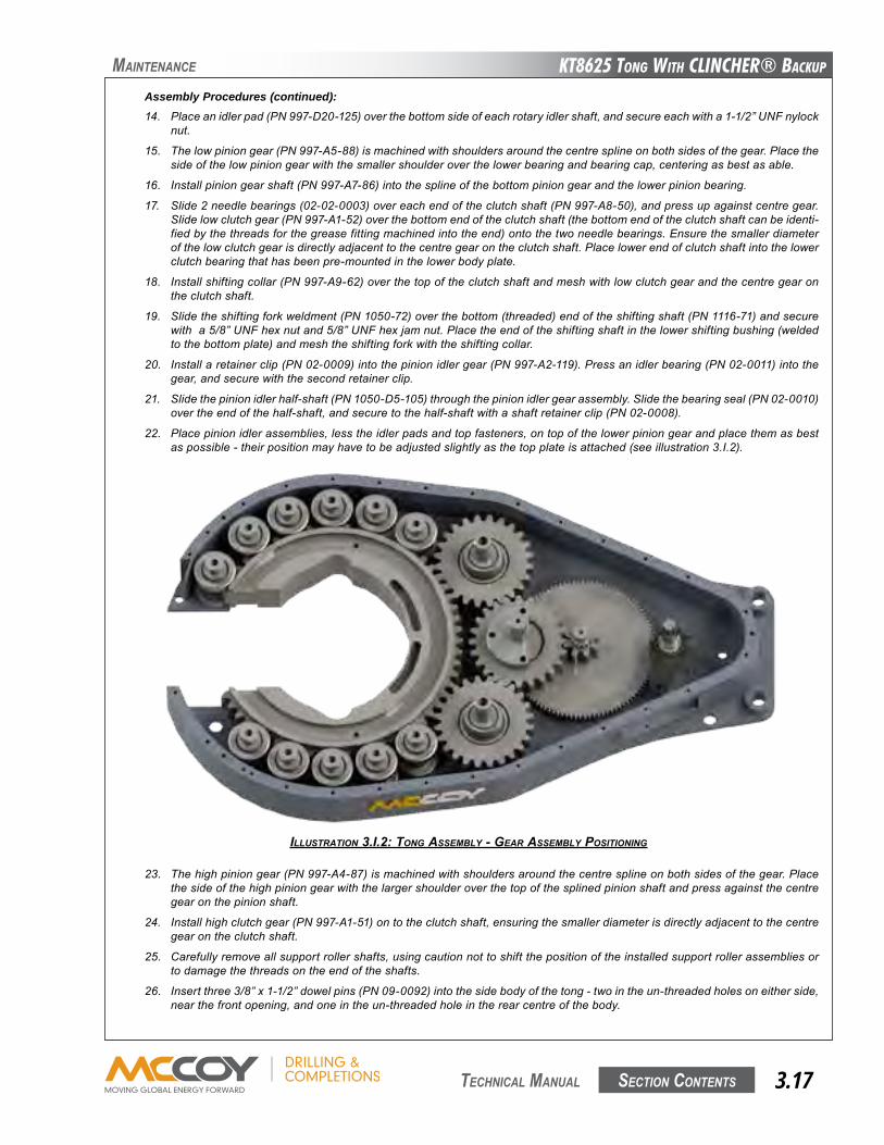
KT8625 Tong WiTh CLinChER® BaCKup
Section contentS 3.17 technical Manual
Assembly Procedures (continued):14. Placeanidlerpad(PN997-D20-125)overthebottomsideofeachrotaryidlershaft,andsecureeachwitha1-1/2”UNFnylock
nut.
15. Thelowpiniongear(PN997-A5-88)ismachinedwithshouldersaroundthecentresplineonbothsidesofthegear.Placethesideofthelowpiniongearwiththesmallershoulderoverthelowerbearingandbearingcap,centeringasbestasable.
16. Installpiniongearshaft(PN997-A7-86)intothesplineofthebottompiniongearandthelowerpinionbearing.
17. Slide2needlebearings(02-02-0003)overeachendoftheclutchshaft(PN997-A8-50),andpressupagainstcentregear.Slidelowclutchgear(PN997-A1-52)overthebottomendoftheclutchshaft(thebottomendoftheclutchshaftcanbeidenti-fiedbythethreadsforthegreasefittingmachinedintotheend)ontothetwoneedlebearings.Ensurethesmallerdiameterofthelowclutchgearisdirectlyadjacenttothecentregearontheclutchshaft.Placelowerendofclutchshaftintothelowerclutchbearingthathasbeenpre-mountedinthelowerbodyplate.
18. Installshiftingcollar(PN997-A9-62)overthetopoftheclutchshaftandmeshwithlowclutchgearandthecentregearontheclutchshaft.
19. Slidetheshiftingforkweldment(PN1050-72)overthebottom(threaded)endoftheshiftingshaft(PN1116-71)andsecurewitha5/8”UNFhexnutand5/8”UNFhexjamnut.Placetheendoftheshiftingshaftinthelowershiftingbushing(weldedtothebottomplate)andmeshtheshiftingforkwiththeshiftingcollar.
20. Installaretainerclip(PN02-0009)intothepinionidlergear(PN997-A2-119).Pressanidlerbearing(PN02-0011)intothegear,andsecurewiththesecondretainerclip.
21. Slidethepinionidlerhalf-shaft(PN1050-D5-105)throughthepinionidlergearassembly.Slidethebearingseal(PN02-0010)overtheendofthehalf-shaft,andsecuretothehalf-shaftwithashaftretainerclip(PN02-0008).
22. Placepinionidlerassemblies,lesstheidlerpadsandtopfasteners,ontopofthelowerpiniongearandplacethemasbestaspossible-theirpositionmayhavetobeadjustedslightlyasthetopplateisattached(seeillustration3.I.2).
Maintenance
ILLUSTRATION 3.I.2: TONg ASSEMBLy - gEAR ASSEMBLy pOSITIONINg
23. Thehighpiniongear(PN997-A4-87)ismachinedwithshouldersaroundthecentresplineonbothsidesofthegear.Placethesideofthehighpiniongearwiththelargershoulderoverthetopofthesplinedpinionshaftandpressagainstthecentregearonthepinionshaft.
24. Installhighclutchgear(PN997-A1-51)ontotheclutchshaft,ensuringthesmallerdiameterisdirectlyadjacenttothecentregearontheclutchshaft.
25. Carefullyremoveallsupportrollershafts,usingcautionnottoshiftthepositionoftheinstalledsupportrollerassembliesortodamagethethreadsontheendoftheshafts.
26. Insertthree3/8”x1-1/2”dowelpins(PN09-0092)intothesidebodyofthetong-twointheun-threadedholesoneitherside,nearthefrontopening,andoneintheun-threadedholeintherearcentreofthebody.
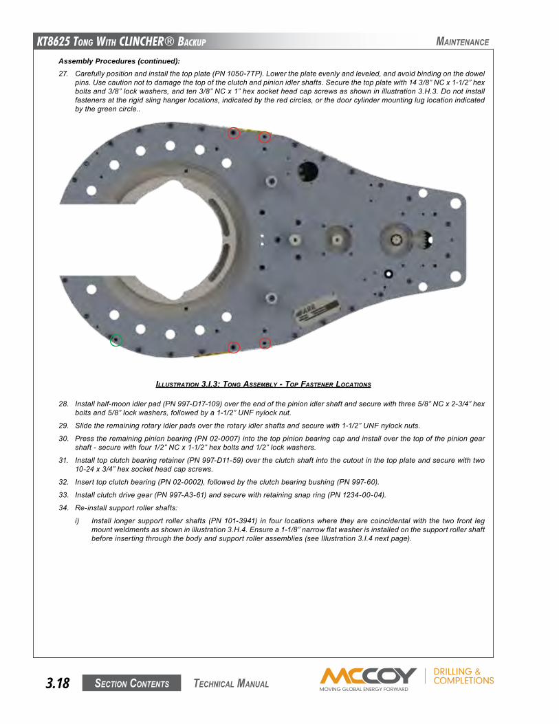
KT8625 Tong WiTh CLinChER® BaCKup
Section contentS3.18 technical Manual
Assembly Procedures (continued):27. Carefullypositionandinstallthetopplate(PN1050-7TP).Lowertheplateevenlyandleveled,andavoidbindingonthedowel
pins.Usecautionnottodamagethetopoftheclutchandpinionidlershafts.Securethetopplatewith143/8”NCx1-1/2”hexboltsand3/8”lockwashers,andten3/8”NCx1”hexsocketheadcapscrewsasshowninillustration3.H.3.Donotinstallfastenersattherigidslinghangerlocations,indicatedbytheredcircles,orthedoorcylindermountingluglocationindicatedbythegreencircle..
28. Installhalf-moonidlerpad(PN997-D17-109)overtheendofthepinionidlershaftandsecurewiththree5/8”NCx2-3/4”hexboltsand5/8”lockwashers,followedbya1-1/2”UNFnylocknut.
29. Slidetheremainingrotaryidlerpadsovertherotaryidlershaftsandsecurewith1-1/2”UNFnylocknuts.
30. Presstheremainingpinionbearing(PN02-0007)intothetoppinionbearingcapandinstalloverthetopofthepiniongearshaft-securewithfour1/2”NCx1-1/2”hexboltsand1/2”lockwashers.
31. Installtopclutchbearingretainer(PN997-D11-59)overtheclutchshaftintothecutoutinthetopplateandsecurewithtwo10-24x3/4”hexsocketheadcapscrews.
32. Inserttopclutchbearing(PN02-0002),followedbytheclutchbearingbushing(PN997-60).
33. Installclutchdrivegear(PN997-A3-61)andsecurewithretainingsnapring(PN1234-00-04).
34. Re-installsupportrollershafts:
i) Install longersupport rollershafts (PN101-3941) in four locationswhere theyarecoincidentalwith the two front legmountweldmentsasshowninillustration3.H.4.Ensurea1-1/8”narrowflatwasherisinstalledonthesupportrollershaftbeforeinsertingthroughthebodyandsupportrollerassemblies(seeIllustration3.I.4nextpage).
ILLUSTRATION 3.I.3: TONg ASSEMBLy - TOp FASTENER LOCATIONS
Maintenance
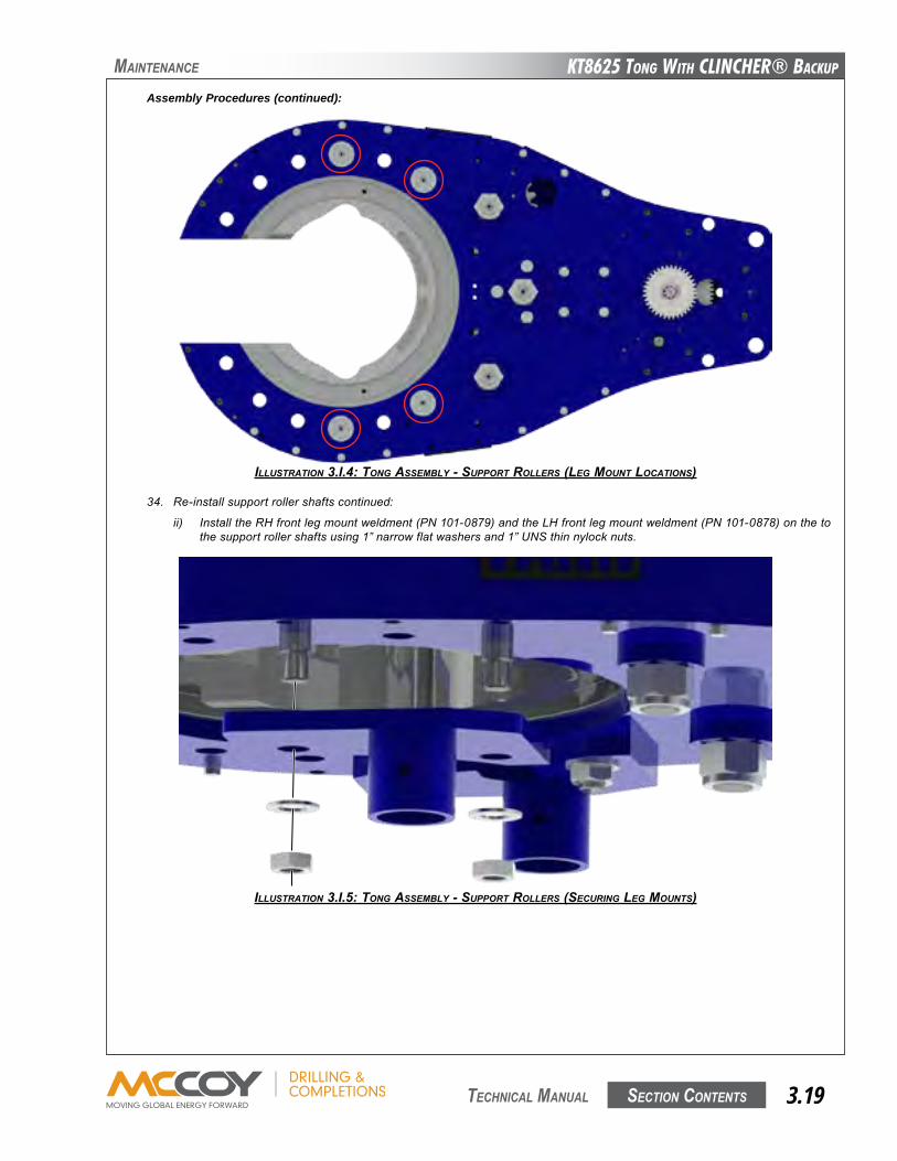
KT8625 Tong WiTh CLinChER® BaCKup
Section contentS 3.19 technical Manual
ILLUSTRATION 3.I.4: TONg ASSEMBLy - SUppORT ROLLERS (LEg MOUNT LOCATIONS)
Maintenance
Assembly Procedures (continued):
34. Re-installsupportrollershaftscontinued:
ii) InstalltheRHfrontlegmountweldment(PN101-0879)andtheLHfrontlegmountweldment(PN101-0878)onthetothesupportrollershaftsusing1”narrowflatwashersand1”UNSthinnylocknuts.
ILLUSTRATION 3.I.5: TONg ASSEMBLy - SUppORT ROLLERS (SECURINg LEg MOUNTS)
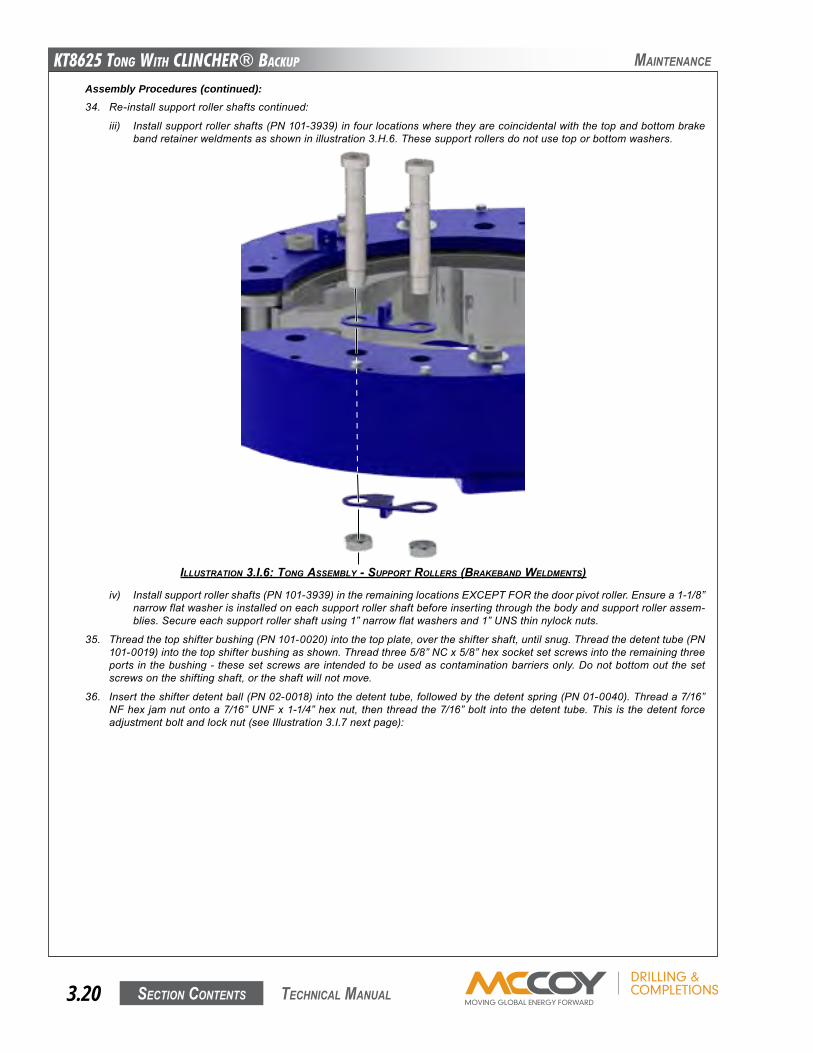
KT8625 Tong WiTh CLinChER® BaCKup
Section contentS3.20 technical Manual
Assembly Procedures (continued):34. Re-installsupportrollershaftscontinued:
iii) Installsupportrollershafts(PN101-3939)infourlocationswheretheyarecoincidentalwiththetopandbottombrakebandretainerweldmentsasshowninillustration3.H.6.Thesesupportrollersdonotusetoporbottomwashers.
ILLUSTRATION 3.I.6: TONg ASSEMBLy - SUppORT ROLLERS (BRAKEBANd wELdMENTS)
Maintenance
iv) Installsupportrollershafts(PN101-3939)intheremaininglocationsEXCEPTFORthedoorpivotroller.Ensurea1-1/8”narrowflatwasherisinstalledoneachsupportrollershaftbeforeinsertingthroughthebodyandsupportrollerassem-blies.Secureeachsupportrollershaftusing1”narrowflatwashersand1”UNSthinnylocknuts.
35. Threadthetopshifterbushing(PN101-0020)intothetopplate,overtheshiftershaft,untilsnug.Threadthedetenttube(PN101-0019)intothetopshifterbushingasshown.Threadthree5/8”NCx5/8”hexsocketsetscrewsintotheremainingthreeports inthebushing-thesesetscrewsareintendedtobeusedascontaminationbarriersonly.Donotbottomoutthesetscrewsontheshiftingshaft,ortheshaftwillnotmove.
36. Inserttheshifterdetentball(PN02-0018)intothedetenttube,followedbythedetentspring(PN01-0040).Threada7/16”NFhex jamnutontoa7/16”UNFx1-1/4”hexnut, thenthreadthe7/16”bolt intothedetent tube.This is thedetent forceadjustmentboltandlocknut(seeIllustration3.I.7nextpage):
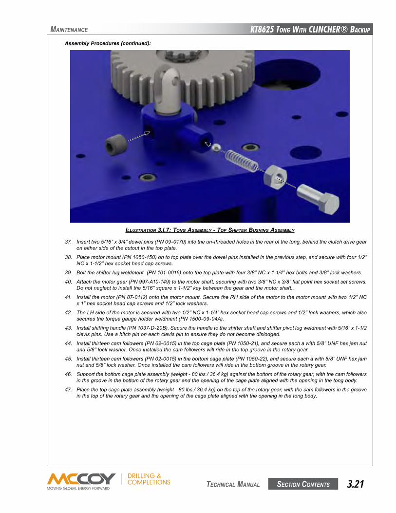
KT8625 Tong WiTh CLinChER® BaCKup
Section contentS 3.21 technical Manual
Assembly Procedures (continued):
37. Inserttwo5/16”x3/4”dowelpins(PN09-0170)intotheun-threadedholesintherearofthetong,behindtheclutchdrivegearoneithersideofthecutoutinthetopplate.
38. Placemotormount(PN1050-150)ontotopplateoverthedowelpinsinstalledinthepreviousstep,andsecurewithfour1/2”NCx1-1/2”hexsocketheadcapscrews.
39. Bolttheshifterlugweldment(PN101-0016)ontothetopplatewithfour3/8”NCx1-1/4”hexboltsand3/8”lockwashers.
40. Attachthemotorgear(PN997-A10-149)tothemotorshaft,securingwithtwo3/8”NCx3/8”flatpointhexsocketsetscrews.Donotneglecttoinstallthe5/16”squarex1-1/2”keybetweenthegearandthemotorshaft..
41. Installthemotor(PN87-0112)ontothemotormount.SecuretheRHsideofthemotortothemotormountwithtwo1/2”NCx1”hexsocketheadcapscrewsand1/2”lockwashers.
42. TheLHsideofthemotorissecuredwithtwo1/2”NCx1-1/4”hexsocketheadcapscrewsand1/2”lockwashers,whichalsosecuresthetorquegaugeholderweldment(PN1500-09-04A).
43. Installshiftinghandle(PN1037-D-20B).Securethehandletotheshiftershaftandshifterpivotlugweldmentwith5/16”x1-1/2clevispins.Useahitchpinoneachclevispintoensuretheydonotbecomedislodged.
44. Installthirteencamfollowers(PN02-0015)inthetopcageplate(PN1050-21),andsecureeachawith5/8”UNFhexjamnutand5/8”lockwasher.Onceinstalledthecamfollowerswillrideinthetopgrooveintherotarygear.
45. Installthirteencamfollowers(PN02-0015)inthebottomcageplate(PN1050-22),andsecureeachawith5/8”UNFhexjamnutand5/8”lockwasher.Onceinstalledthecamfollowerswillrideinthebottomgrooveintherotarygear.
46. Supportthebottomcageplateassembly(weight-80lbs/36.4kg)againstthebottomoftherotarygear,withthecamfollowersinthegrooveinthebottomoftherotarygearandtheopeningofthecageplatealignedwiththeopeninginthetongbody.
47. Placethetopcageplateassembly(weight-80lbs/36.4kg)onthetopoftherotarygear,withthecamfollowersinthegrooveinthetopoftherotarygearandtheopeningofthecageplatealignedwiththeopeninginthetongbody.
ILLUSTRATION 3.I.7: TONg ASSEMBLy - TOp SHIFTER BUSHINg ASSEMBLy
Maintenance
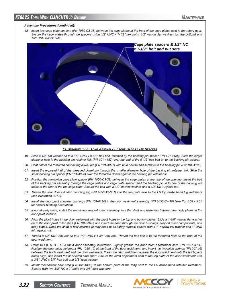
KT8625 Tong WiTh CLinChER® BaCKup
Section contentS3.22 technical Manual
Assembly Procedures (continued):48. Inserttwocageplatespacers(PN1050-C3-38)betweenthecageplatesatthefrontofthecageplatesnexttotherotarygear.
Securethecageplatesthroughthespacersusing1/2”UNCx7-1/2”hexbolts,1/2”narrowflatwashers(onthebottom)and1/2”UNCnylocknuts.
49. Slidea1/2”flatwasherontoa1/2”UNCx9-1/2”hexbolt,followedbythebackingpinspacer(PN101-4186).Slidethelargerdiameterholeinthebackingpinretainerlink(PN101-4187)evertheendofthe9-1/2”hexboltontothebackingpinspacer.
50. Coathalfofthethreadedconnectingdowelpin(PN101-4097)withblueLoctiteandscrewintothebackingpin(PN101-4188).
51. Inserttheexposedhalfofthethreadeddowelpinthroughthesmallerdiameterholeofthebackingpinretainerlink.Slidethesmallbackingpinspacer(PN101-4096)overthethreadeddowelagainstthebackingpinretainerlin
52. Positiontheremainingcageplatespacer(PN1050-C3-38)betweenthecageplatesattherearoftheopening.Inserttheboltofthebackingpinassemblythroughthecageplatesandcageplatespacer,andthebackingpinintooneofthebackingpinholesattherearofthetopcageplate.Securetheboltwitha1/2”narrowwasheranda1/2”UNCnylocknut.
53. Threadthereardoorcylindermountinglug(PN1050-12-001)intothetopplatenexttotheLHtopbrakebandlugweldment(seeillustration3.H.3).
54. Installthedoorpivotshoulderbushings(PN101-0110)inthedoorweldmentassembly(PN1050-C4-10)(seePp.5.34-5.35forcorrectbushingorientation).
55. Ifnotalreadydone,installtheremainingsupportrollerassemblylesstheshaftandfastenersbetweenthebodyplatesinthedoorpivotlocation.
56. Alignthepivotholesinthedoorweldmentwiththepivotholesinthetopandbottomplates.Slidea1-1/8”narrowflatwasherontothedoorpivotrollershaft(PN101-3940)andinserttheshaftthroughthedoorbushings,supportrollercomponents,andbodyplates.Oncetheshaftisfullyinserted(itmayneedtobelightlytapped)securewitha1”narrowflatwasherand1”UNSthinnylocknut.
57. Threada1/2”UNChexnutontoa1/2”UNCx1-3/4”hexbolt.Threadthehexboltintothethreadedholeonthefrontofthedoorweldment.
58. Refer to Pp. 5.34 - 5.35 for a door assembly illustration. Lightly grease the door latch adjustment cam (PN 1037-A-14).Positionthedoorlatchweldment(PN1050-15)atthefrontofthedoorweldment,andinsertthetwolatchsprings(PN997-16)betweenthelatchweldmentandthedoorweldment.Pressthelatchweldmentagainstthedoorweldmentuntilthelatchpivotholesalign,andinsertthedoorlatchcamshaft.Securethelatchadjustmentcamtothetopplateofthedoorweldmentwitha3/8”UNCx3/4”hexboltand3/8”lockwasher.
59. Installmechanicaldoorstop (PN101-1833) to thebottomplateof the tongnext to theLHbrakebandretainerweldment.Securewithtwo3/8”NCx2”boltsand3/8”lockwashers.
ILLUSTRATION 3.I.8: TONg ASSEMBLy - FRONT CAgE pLATE SpACERS
Maintenance
Cage plate spacers & 1/2” NC x 7-1/2” bolt and nut sets
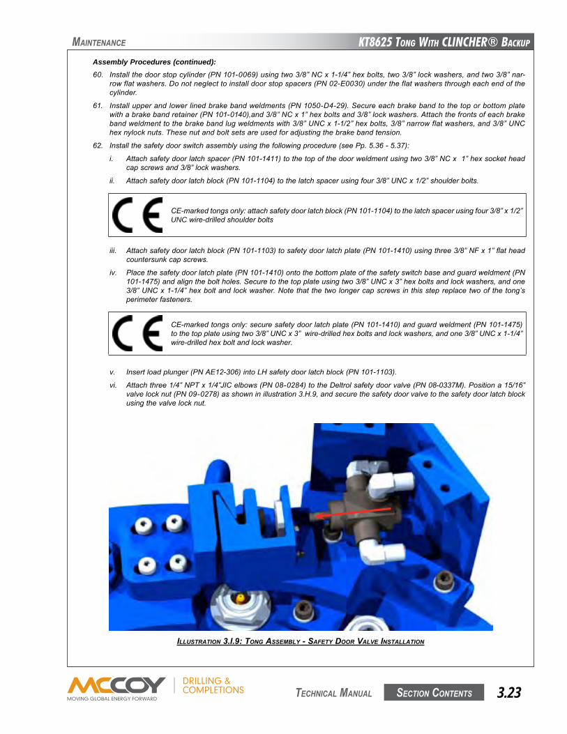
KT8625 Tong WiTh CLinChER® BaCKup
Section contentS 3.23 technical Manual
Assembly Procedures (continued):60. Installthedoorstopcylinder(PN101-0069)usingtwo3/8”NCx1-1/4”hexbolts,two3/8”lockwashers,andtwo3/8”nar-
rowflatwashers.Donotneglecttoinstalldoorstopspacers(PN02-E0030)undertheflatwashersthrougheachendofthecylinder.
61. Installupperandlowerlinedbrakebandweldments(PN1050-D4-29).Secureeachbrakebandtothetoporbottomplatewithabrakebandretainer(PN101-0140),and3/8”NCx1”hexboltsand3/8”lockwashers.Attachthefrontsofeachbrakebandweldmenttothebrakebandlugweldmentswith3/8”UNCx1-1/2”hexbolts,3/8”narrowflatwashers,and3/8”UNChexnylocknuts.Thesenutandboltsetsareusedforadjustingthebrakebandtension.
62. Installthesafetydoorswitchassemblyusingthefollowingprocedure(seePp.5.36-5.37):
i. Attachsafetydoorlatchspacer(PN101-1411)tothetopofthedoorweldmentusingtwo3/8”NCx1”hexsocketheadcapscrewsand3/8”lockwashers.
ii. Attachsafetydoorlatchblock(PN101-1104)tothelatchspacerusingfour3/8”UNCx1/2”shoulderbolts.
ILLUSTRATION 3.I.9: TONg ASSEMBLy - SAFETy dOOR vALvE INSTALLATION
Maintenance
CE-markedtongsonly:attachsafetydoorlatchblock(PN101-1104)tothelatchspacerusingfour3/8”x1/2”UNCwire-drilledshoulderbolts
iii. Attachsafetydoorlatchblock(PN101-1103)tosafetydoorlatchplate(PN101-1410)usingthree3/8”NFx1”flatheadcountersunkcapscrews.
iv. Placethesafetydoorlatchplate(PN101-1410)ontothebottomplateofthesafetyswitchbaseandguardweldment(PN101-1475)andaligntheboltholes.Securetothetopplateusingtwo3/8”UNCx3”hexboltsandlockwashers,andone3/8”UNCx1-1/4”hexboltandlockwasher.Notethatthetwolongercapscrewsinthisstepreplacetwoofthetong’sperimeterfasteners.
v. Insertloadplunger(PNAE12-306)intoLHsafetydoorlatchblock(PN101-1103).
vi. Attachthree1/4”NPTx1/4”JICelbows(PN08-0284)totheDeltrolsafetydoorvalve(PN08-0337M).Positiona15/16”valvelocknut(PN09-0278)asshowninillustration3.H.9,andsecurethesafetydoorvalvetothesafetydoorlatchblockusingthevalvelocknut.
CE-markedtongsonly:securesafetydoorlatchplate(PN101-1410)andguardweldment(PN101-1475)tothetopplateusingtwo3/8”UNCx3”wire-drilledhexboltsandlockwashers,andone3/8”UNCx1-1/4”wire-drilledhexboltandlockwasher.
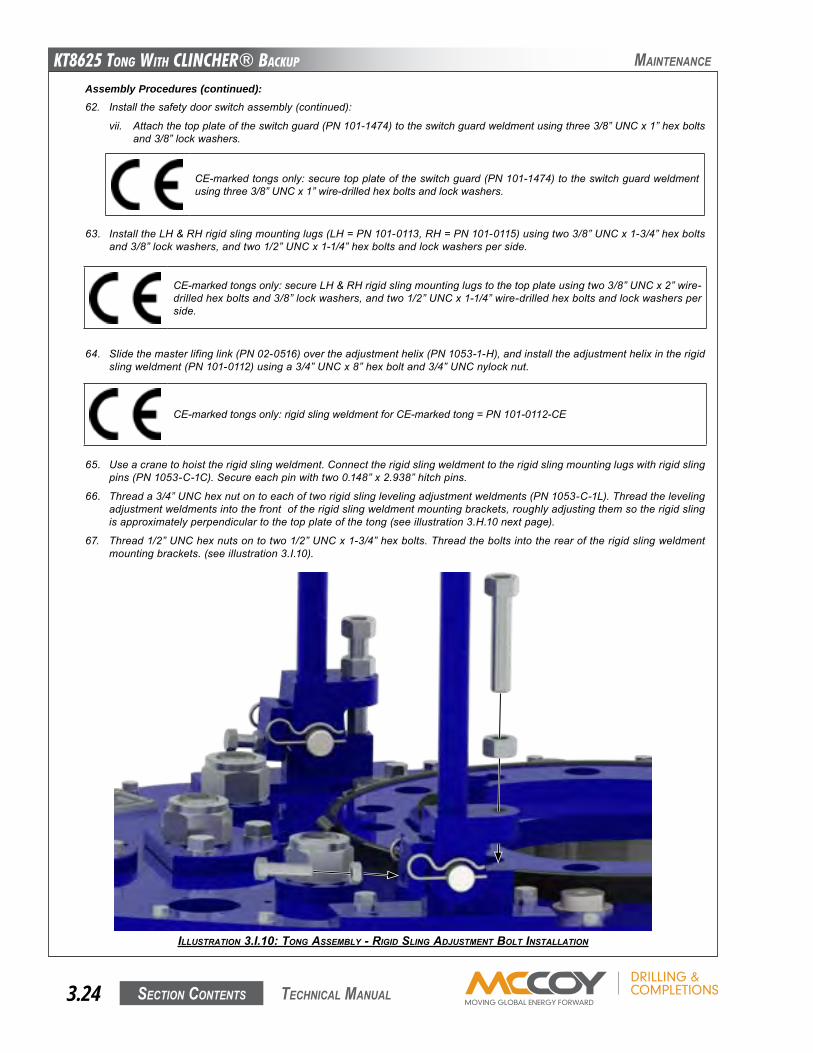
KT8625 Tong WiTh CLinChER® BaCKup
Section contentS3.24 technical Manual
ILLUSTRATION 3.I.10: TONg ASSEMBLy - RIgId SLINg AdJUSTMENT BOLT INSTALLATION
Maintenance
Assembly Procedures (continued):62. Installthesafetydoorswitchassembly(continued):
vii. Attachthetopplateoftheswitchguard(PN101-1474)totheswitchguardweldmentusingthree3/8”UNCx1”hexboltsand3/8”lockwashers.
CE-markedtongsonly:securetopplateoftheswitchguard(PN101-1474)totheswitchguardweldmentusingthree3/8”UNCx1”wire-drilledhexboltsandlockwashers.
64. Slidethemasterlifinglink(PN02-0516)overtheadjustmenthelix(PN1053-1-H),andinstalltheadjustmenthelixintherigidslingweldment(PN101-0112)usinga3/4”UNCx8”hexboltand3/4”UNCnylocknut.
63. InstalltheLH&RHrigidslingmountinglugs(LH=PN101-0113,RH=PN101-0115)usingtwo3/8”UNCx1-3/4”hexboltsand3/8”lockwashers,andtwo1/2”UNCx1-1/4”hexboltsandlockwashersperside.
CE-markedtongsonly:secureLH&RHrigidslingmountinglugstothetopplateusingtwo3/8”UNCx2”wire-drilledhexboltsand3/8”lockwashers,andtwo1/2”UNCx1-1/4”wire-drilledhexboltsandlockwashersperside.
65. Useacranetohoisttherigidslingweldment.Connecttherigidslingweldmenttotherigidslingmountinglugswithrigidslingpins(PN1053-C-1C).Secureeachpinwithtwo0.148”x2.938”hitchpins.
66. Threada3/4”UNChexnutontoeachoftworigidslinglevelingadjustmentweldments(PN1053-C-1L).Threadthelevelingadjustmentweldmentsintothefrontoftherigidslingweldmentmountingbrackets,roughlyadjustingthemsotherigidslingisapproximatelyperpendiculartothetopplateofthetong(seeillustration3.H.10nextpage).
67. Thread1/2”UNChexnutsontotwo1/2”UNCx1-3/4”hexbolts.Threadtheboltsintotherearoftherigidslingweldmentmountingbrackets.(seeillustration3.I.10).
CE-markedtongsonly:rigidslingweldmentforCE-markedtong=PN101-0112-CE
KT8625 Tong WiTh CLinChER® BaCKup
Section contentS 3.25 technical Manual
Assembly Procedures (continued):69. Useacraneandtemporaryslingtohoistthebackupassembly(weight=910lbs/414kg)ontoasuitablesupportstructure
nexttotheassemblylocationofthetong.Minimumheightforthebackupsupportsmustbe36”inordertoallowclearanceforinstallingthefrontlegs.
70. Attachtherearlegassemblytothetong:
a. Positionrearlegweldment(1302-908-00)onaflatsurfacenearthetongassemblylocation.
● Models80-0615,80-0615-2,&80-0615-6userearlegweldmentPN1302-908-00● Models80-0615-3&80-0615-4userearlegweldmentPN101-2031
b. Useacranetohoistthetongassemblyofftheassemblysurface.Bringthetongintocontactwiththerearleg,ensuringthecranecontinuestosupporttheentireweightofthetong.Attachtherearlegweldmenttothetongusingtwo1-1/4”UNCx9”hexboltsand1-1/4”UNCheavyhexnuts,andtwo1”UNCx8”hexboltsand1”UNCheavyhexnuts.
71. 80-0615-6 assembly (uses 85-0607 backup) only: installtherearbackupsupportspringassemblyintherearleg(seePp.5.40-5.41):
a. Placetwosprings(PN991-13)inthebottomsupportweldment(PN101-4495).Placethetopsupportweldment(PN101-4496)overthespringsandusefour1/2”UNCx6”hexbolts,1/2”narrowflatwashers,and1/2”UNChexnylocknutstofastentheassemblytogether.
b. Installthespringsupportweldmentintherearlegusingtwo1/2”UNCx9-1/2”hexbolts,1/2”narrowflatwashers,and1/2”UNChexnylocknuts.Thelocationofthesupportcanbechangedasrequiredwhenlevelingthebackup.
72. 85-0604 and 85-0606 backup assemblies only:ifusingeitherofthesebackupsensuretheyareproperlypreparedformatingwiththetongandrearlegassembly.RefertoPp.5.40-5.41.
a. Threada1-1/4”UNCheavyhexnutontothe1-1/4”UNCx8”threadedrod(PN101-1993).b. Coatapproximately2”ofthreadonthebottomofthethreadedrodwithblueLoctite®.Screwthecoatedpartofthethreaded
rodintotheheavyhexboltweldedtothetopplateofthebackupuntiltherodbottomsout.Lockthethreadedrodinplaceusingtheheavyhexnutthreadedontotherodinthepreviousstep.
c. Coatapproximately4”ofthreadatthetopofthethreadedrodwithblueLoctite®.Threadona1-1/4”UNCheavyhexnut,ensuringenoughthreadisexposedtoallowinstallationofthesuspensionspringv-bracketandanother1-1/4”UNCheavyhexnut.
d. Installthesuspensionspringv-bracket(PN1483-500-00-04)ontothethreadedrod,andsecurewithanother1-1/4”UNCheavyhexnut.
73. Removethesidepanelsfromthebackup.
74. Useacranetohoistthetongandrearlegassemblyandplaceinpositionoverthebackup.Ifusingthe85-0604or85-0607-1compressionloadcell-stylebackupstherearlegmustbeguidedsothatthe“paddle”onthebackupsitsbetweentheverticalplatesoftherearlegasthetongandrearlegassemblyareloweredoverthebackup.
Maintenance
CE-markedtongsonly:placearubberprotectivewasher(PN101-5733)onthetopplateofthebackupovereachfrontlegopening.Thefrontlegswillbeinsertedthroughtheseprotectivewashers.
75. Holdatopspringcap(PN1302-905-03B)underthetopplateofthebackup,andinsertafrontlegtube(PN1302-904-905C)fromthebottomofthebackup,throughthespringcap,andintothelegmountweldmentonthetong.Securethelegtubewitha7/16”UNCx4”hexbolt,7/16”narrowflatwasher,anda7/16”UNCnylocknut.Repeatfortheotherlegtube.
76. Slidealegspring(PN1391-905-02B)overthebottomofeachlegtube,followedbyabottomspringcap(PN1302-905-03C).Secureeachlegspringandbottomspringcaptothelegtubeusinga7/16”UNCx3”hexbolt,7/16”narrowflatwasher,anda7/16”UNCnylocknut.
CE-markedtongsonly:thefollowingfrontleginstallationstepssupersedesteps75&76below.
•slidealowerspringwasher(PN1302-905-03Aoverthetopofeach“CE-marked”frontlegweldment(PN101-5732).Temporarilypre-positionthelowerspringwashersonthefrontlegsbyinstalling7/16”UNCx3”bolts,flatwashersand7/16”UNCnylocknutsunderthefrontlegwashers.Thelowerfrontlegspringwashersmayneedtobeadjustedoncethefinalpositionofthebackupisdetermined.
•slideafrontlegspring(1391-905-03A)overthetopofeach“CE-marked”frontlegweldment.
•holdatopspringcap(PN1302-905-03B)underthetopplateofthebackup,andinsertthe“CE-marked”frontlegweldmentthroughthetopspringwasher,theprotectiverubberwasher,andsecureeachlegweldmenttothelegmountweldmentsonthetongusinga7/16”UNCx4”hexbolt,7/16”narrowflatwasher,anda7/16”UNCnylocknut.
KT8625 Tong WiTh CLinChER® BaCKup
Section contentS3.26 technical Manual
Maintenance
Assembly Procedures (continued):77. 85-0604 and 85-0606 backup assemblies only:
a. Threada3/8”NCshoulderpattern2-Aeyeboltintothetongbodyfromthebottomofthetopplateoftherearlegweld-ment,nearthefrontoftherearleg(seePp.5.42-5.43).
b. Connectoneendofarearbackupsupportspring(PN1391-905-03)tooneoftheeyeboltsinstalledinthepreviousstep,andtheotherendofthespringtothev-bracketinstalledinstep71d.Securetheendofthespringtothev-bracketusingaspringretainer(PN1480-500-00-04B)andacotterpin.Repeatforthesecondspring.
78. Hoisttongandbackupassemblyoffthebackupsupports,andlowerassemblysothatitsitsonitslegs.
79. Installgreasefittings:
a) Installone1/4”straightthreadgreasefitting(PN02-0097)intothetopsideofeachsupportrollershaft, includingthedoorpivotrollers(12locationstotal).
b) Installone1/4”straightthreadgreasefitting(PN02-0097)intothetopsideofthelatchadjustmentcam.c) Installone1/8”NPTgreasefitting(PN02-0005)intothetopofeachidlershaftorhalf-shaft(threelocationstotal).d) Installone1/8”NPTgreasefitting(PN02-0005)intotheendoftheclutchshaft,inthecentreoftheclutchbearingcap.e) Installtwo1/8”NPT90ogreasefittings(PN02-0093)ineachpinionbearingcap(fourlocationstotal).f) Installtwo1/8”NPT90ogreasefittings(PN02-0093)inclutchbearingcap(twolocationstotal).g) Installone1/8”NPT90ogreasefitting(PN02-0093)orone1/8”NPT45ogreasefitting(PN02-0006)inthetopofthe
motormount.h) Install two1/8”NPT90ogrease fittings (PN02-0093) into the topplateof thebackupdirectlyaboveeachclamping
cylinder,andtwointothebottombackupplatedirectlybeneatheachoftheclampingcylinders(eightlocationstotal).
i) Installdrive-ingreasefittings(PN02-0012)intotheendsofeachcageplatecamfollower(26locationstotal).
80. Installhydraulicinletsupportbase(PN101-1138)tothetopplatedirectlyadjacenttotheRHrotaryidler,usingtwo3/8”NCx1”hexboltsand3/8”lockwashers.Attachtheadjustmentplate(PN101-0022)tothesupportbaseusingtwo3/8”NCx1”hexbolts,3/8”narrowflatwashers,and3/8”UNChexnylocknuts.
81. Attachtheoutletcouplingsupportmountingbase(PN101-0021)tothetopplatetotheRHsideofthemotormountusingfour3/8”UNCx2”hexsocketheadcapscrews.
82. Attachtheoutletcouplingsupportweldment(PN101-0023)totheweldmentmountusingtwo3/8”NCx1”hexboltsand3/8”lockwashers.Attachtheadjustmentplate(PN101-0277)totheoutletsupportweldmentusingfour3/8”NCx1”hexbolts,3/8”narrowflatwashers,and3/8”UNChexnylocknuts.
83. Coatthethreadsofthehydraulicvalvemountingposts(PN101-0116)withLoctiteandthreadintothetopplatejustbehindthebrakebandoneithersideofthebrakebandretainer.
84. MounttheDVA35hydraulicvalveassemblyonthemountingpostsusingtwo1/2”UNCx4-1/2”hexboltsand1/2”narrowflatwashers.
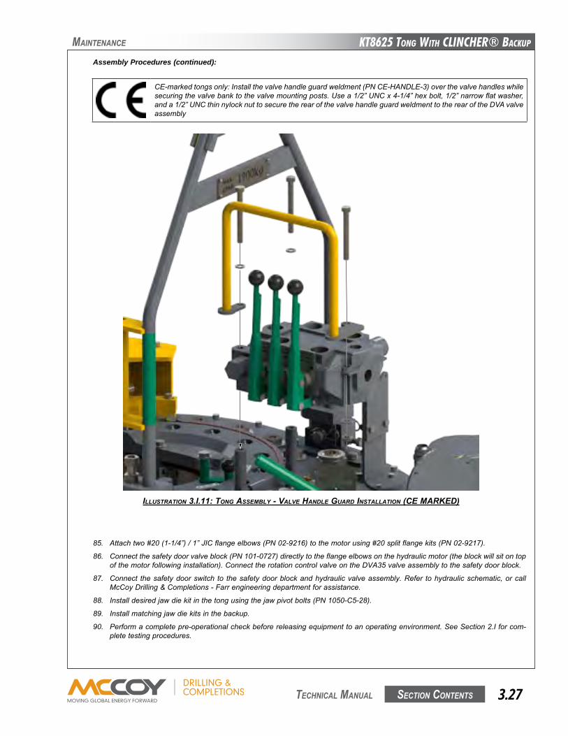
KT8625 Tong WiTh CLinChER® BaCKup
Section contentS 3.27 technical Manual
Maintenance
CE-markedtongsonly:Installthevalvehandleguardweldment(PNCE-HANDLE-3)overthevalvehandleswhilesecuringthevalvebanktothevalvemountingposts.Usea1/2”UNCx4-1/4”hexbolt,1/2”narrowflatwasher,anda1/2”UNCthinnylocknuttosecuretherearofthevalvehandleguardweldmenttotherearoftheDVAvalveassembly
85. Attachtwo#20(1-1/4”)/1”JICflangeelbows(PN02-9216)tothemotorusing#20splitflangekits(PN02-9217).
86. Connectthesafetydoorvalveblock(PN101-0727)directlytotheflangeelbowsonthehydraulicmotor(theblockwillsitontopofthemotorfollowinginstallation).ConnecttherotationcontrolvalveontheDVA35valveassemblytothesafetydoorblock.
87. Connect thesafetydoorswitch to thesafetydoorblockandhydraulicvalveassembly.Refer tohydraulicschematic,orcallMcCoyDrilling&Completions-Farrengineeringdepartmentforassistance.
88. Installdesiredjawdiekitinthetongusingthejawpivotbolts(PN1050-C5-28).
89. Installmatchingjawdiekitsinthebackup.
90. Performacompletepre-operationalcheckbeforereleasingequipmenttoanoperatingenvironment.SeeSection2.Iforcom-pletetestingprocedures.
Assembly Procedures (continued):
ILLUSTRATION 3.I.11: TONg ASSEMBLy - vALvE HANdLE gUARd INSTALLATION (CE MARKEd)
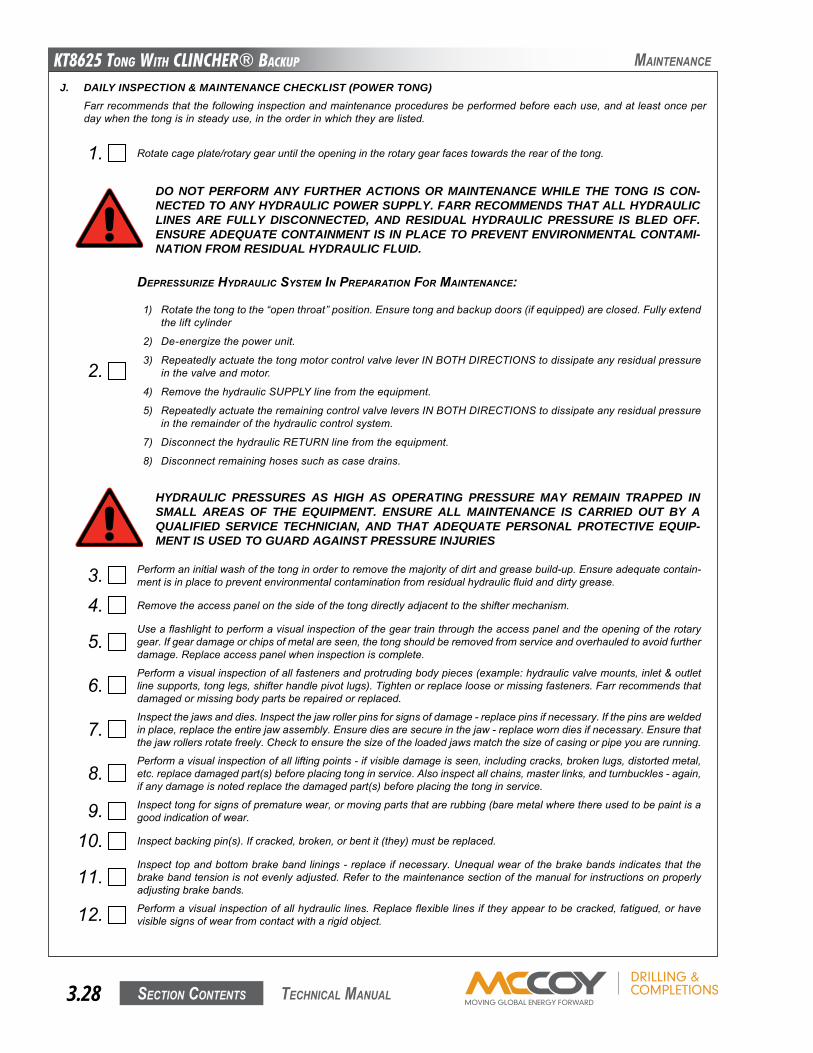
KT8625 Tong WiTh CLinChER® BaCKup
Section contentS3.28 technical Manual
J. DAILY INSPECTION & MAINTENANCE CHECKLIST (POWER TONG)Farrrecommendsthatthefollowinginspectionandmaintenanceproceduresbeperformedbeforeeachuse,andatleastonceperdaywhenthetongisinsteadyuse,intheorderinwhichtheyarelisted.
1. Rotatecageplate/rotarygearuntiltheopeningintherotarygearfacestowardstherearofthetong.
3. Performaninitialwashofthetonginordertoremovethemajorityofdirtandgreasebuild-up.Ensureadequatecontain-mentisinplacetopreventenvironmentalcontaminationfromresidualhydraulicfluidanddirtygrease.
4. Removetheaccesspanelonthesideofthetongdirectlyadjacenttotheshiftermechanism.
5.Useaflashlighttoperformavisualinspectionofthegeartrainthroughtheaccesspanelandtheopeningoftherotarygear.Ifgeardamageorchipsofmetalareseen,thetongshouldberemovedfromserviceandoverhauledtoavoidfurtherdamage.Replaceaccesspanelwheninspectioniscomplete.
6.Performavisualinspectionofallfastenersandprotrudingbodypieces(example:hydraulicvalvemounts,inlet&outletlinesupports,tonglegs,shifterhandlepivotlugs).Tightenorreplacelooseormissingfasteners.Farrrecommendsthatdamagedormissingbodypartsberepairedorreplaced.
7.Inspectthejawsanddies.Inspectthejawrollerpinsforsignsofdamage-replacepinsifnecessary.Ifthepinsareweldedinplace,replacetheentirejawassembly.Ensurediesaresecureinthejaw-replaceworndiesifnecessary.Ensurethatthejawrollersrotatefreely.Checktoensurethesizeoftheloadedjawsmatchthesizeofcasingorpipeyouarerunning.
8.Performavisualinspectionofallliftingpoints-ifvisibledamageisseen,includingcracks,brokenlugs,distortedmetal,etc.replacedamagedpart(s)beforeplacingtonginservice.Alsoinspectallchains,masterlinks,andturnbuckles-again,ifanydamageisnotedreplacethedamagedpart(s)beforeplacingthetonginservice.
9. Inspecttongforsignsofprematurewear,ormovingpartsthatarerubbing(baremetalwherethereusedtobepaintisagoodindicationofwear.
10. Inspectbackingpin(s).Ifcracked,broken,orbentit(they)mustbereplaced.
11.Inspecttopandbottombrakebandlinings-replaceifnecessary.Unequalwearofthebrakebandsindicatesthatthebrakebandtensionisnotevenlyadjusted.Refertothemaintenancesectionofthemanualforinstructionsonproperlyadjustingbrakebands.
12. Performavisualinspectionofallhydrauliclines.Replaceflexiblelinesiftheyappeartobecracked,fatigued,orhavevisiblesignsofwearfromcontactwitharigidobject.
DO NOT PERFORM ANY FURTHER ACTIONS OR MAINTENANCE WHILE THE TONG IS CON-NECTED TO ANY HYDRAULIC POWER SUPPLY. FARR RECOMMENDS THAT ALL HYDRAULIC LINES ARE FULLY DISCONNECTED, AND RESIDUAL HYDRAULIC PRESSURE IS BLED OFF. ENSURE ADEQUATE CONTAINMENT IS IN PLACE TO PREVENT ENVIRONMENTAL CONTAMI-NATION FROM RESIDUAL HYDRAULIC FLUID.
2.
dEpRESSURIzE HydRAULIC SySTEM IN pREpARATION FOR MAINTENANCE:
1) Rotatethetongtothe“openthroat”position.Ensuretongandbackupdoors(ifequipped)areclosed.Fullyextendtheliftcylinder
2) De-energizethepowerunit.
3) RepeatedlyactuatethetongmotorcontrolvalveleverINBOTHDIRECTIONStodissipateanyresidualpressureinthevalveandmotor.
4) RemovethehydraulicSUPPLYlinefromtheequipment.
5) RepeatedlyactuatetheremainingcontrolvalveleversINBOTHDIRECTIONStodissipateanyresidualpressureintheremainderofthehydrauliccontrolsystem.
7) DisconnectthehydraulicRETURNlinefromtheequipment.
8) Disconnectremaininghosessuchascasedrains.
HYDRAULIC PRESSURES AS HIGH AS OPERATING PRESSURE MAY REMAIN TRAPPED IN SMALL AREAS OF THE EQUIPMENT. ENSURE ALL MAINTENANCE IS CARRIED OUT BY A QUALIFIED SERVICE TECHNICIAN, AND THAT ADEQUATE PERSONAL PROTECTIVE EQUIP-MENT IS USED TO GUARD AGAINST PRESSURE INJURIES
Maintenance
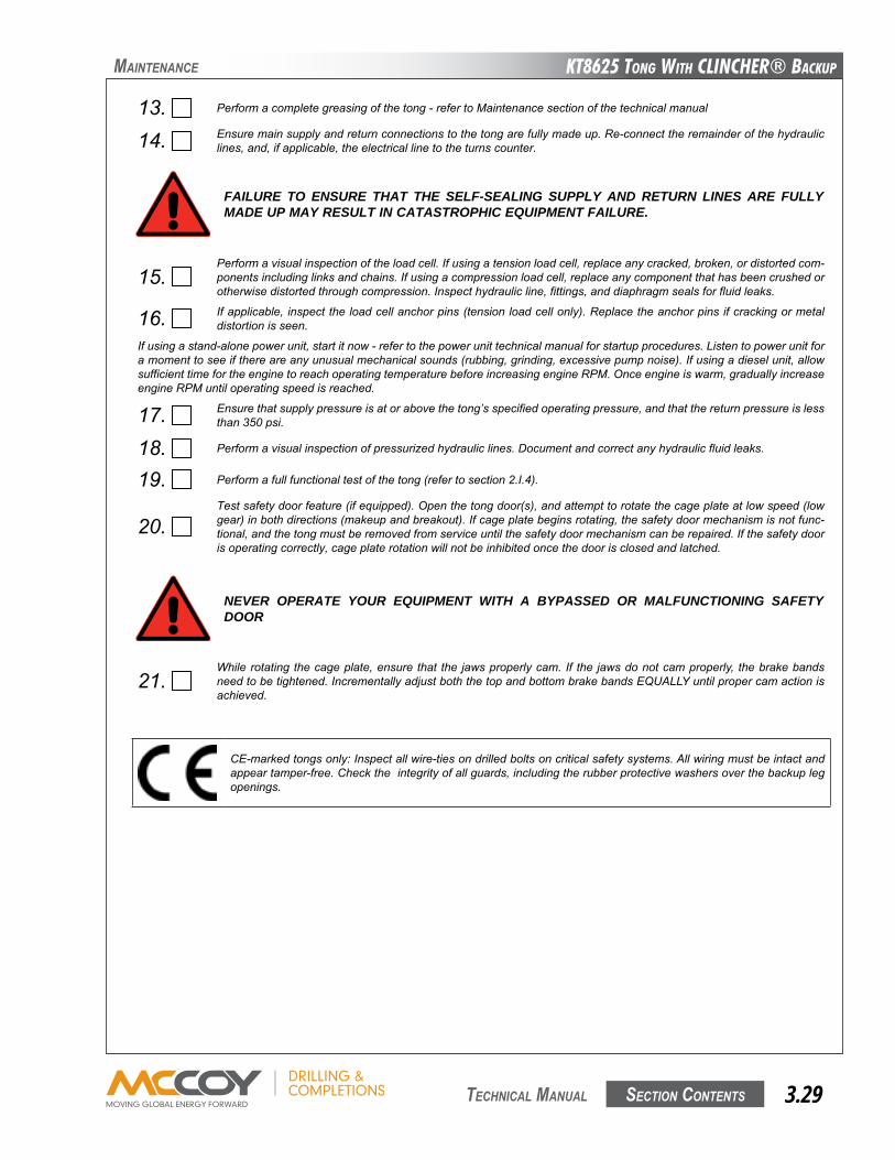
KT8625 Tong WiTh CLinChER® BaCKup
Section contentS 3.29 technical Manual
21.Whilerotatingthecageplate,ensurethatthejawsproperlycam.If the jawsdonotcamproperly, thebrakebandsneedtobetightened.IncrementallyadjustboththetopandbottombrakebandsEqUALLYuntilpropercamactionisachieved.
13. Performacompletegreasingofthetong-refertoMaintenancesectionofthetechnicalmanual
14. Ensuremainsupplyandreturnconnectionstothetongarefullymadeup.Re-connecttheremainderofthehydrauliclines,and,ifapplicable,theelectricallinetotheturnscounter.
FAILURE TO ENSURE THAT THE SELF-SEALING SUPPLY AND RETURN LINES ARE FULLY MADE UP MAY RESULT IN CATASTROPHIC EQUIPMENT FAILURE.
NEVER OPERATE YOUR EQUIPMENT WITH A BYPASSED OR MALFUNCTIONING SAFETY DOOR
15.Performavisualinspectionoftheloadcell.Ifusingatensionloadcell,replaceanycracked,broken,ordistortedcom-ponentsincludinglinksandchains.Ifusingacompressionloadcell,replaceanycomponentthathasbeencrushedorotherwisedistortedthroughcompression.Inspecthydraulicline,fittings,anddiaphragmsealsforfluidleaks.
16. Ifapplicable,inspecttheloadcellanchorpins(tensionloadcellonly).Replacetheanchorpinsifcrackingormetaldistortionisseen.
Ifusingastand-alonepowerunit,startitnow-refertothepowerunittechnicalmanualforstartupprocedures.Listentopowerunitforamomenttoseeifthereareanyunusualmechanicalsounds(rubbing,grinding,excessivepumpnoise).Ifusingadieselunit,allowsufficienttimefortheenginetoreachoperatingtemperaturebeforeincreasingengineRPM.Onceengineiswarm,graduallyincreaseengineRPMuntiloperatingspeedisreached.
17. Ensurethatsupplypressureisatorabovethetong’sspecifiedoperatingpressure,andthatthereturnpressureislessthan350psi.
18. Performavisualinspectionofpressurizedhydrauliclines.Documentandcorrectanyhydraulicfluidleaks.
19. Performafullfunctionaltestofthetong(refertosection2.I.4).
20.Testsafetydoorfeature(ifequipped).Openthetongdoor(s),andattempttorotatethecageplateatlowspeed(lowgear)inbothdirections(makeupandbreakout).Ifcageplatebeginsrotating,thesafetydoormechanismisnotfunc-tional,andthetongmustberemovedfromserviceuntilthesafetydoormechanismcanberepaired.Ifthesafetydoorisoperatingcorrectly,cageplaterotationwillnotbeinhibitedoncethedoorisclosedandlatched.
Maintenance
CE-markedtongsonly:Inspectallwire-tiesondrilledboltsoncriticalsafetysystems.Allwiringmustbeintactandappeartamper-free.Checktheintegrityofallguards,includingtherubberprotectivewashersoverthebackuplegopenings.
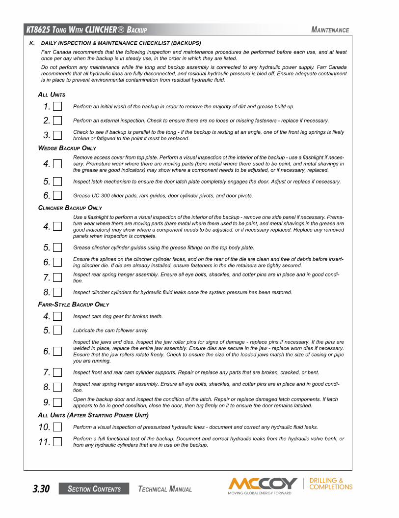
KT8625 Tong WiTh CLinChER® BaCKup
Section contentS3.30 technical Manual
Maintenance
K. DAILY INSPECTION & MAINTENANCE CHECKLIST (BACKUPS)FarrCanadarecommendsthat thefollowing inspectionandmaintenanceproceduresbeperformedbeforeeachuse,andat leastonceperdaywhenthebackupisinsteadyuse,intheorderinwhichtheyarelisted.
Donotperformanymaintenancewhile the tongandbackupassembly isconnected toanyhydraulicpowersupply.FarrCanadarecommendsthatallhydrauliclinesarefullydisconnected,andresidualhydraulicpressureisbledoff.Ensureadequatecontainmentisinplacetopreventenvironmentalcontaminationfromresidualhydraulicfluid.
ALL UNITS
1. Performaninitialwashofthebackupinordertoremovethemajorityofdirtandgreasebuild-up.
2. Performanexternalinspection.Checktoensuretherearenolooseormissingfasteners-replaceifnecessary.
3. Checktoseeifbackupisparalleltothetong-ifthebackupisrestingatanangle,oneofthefrontlegspringsislikelybrokenorfatiguedtothepointitmustbereplaced.
wEdgE BACKUp ONLy
4.Removeaccesscoverfromtopplate.Performavisualinspectionottheinteriorofthebackup-useaflashlightifneces-sary.Prematurewearwheretherearemovingparts(baremetalwherethereusedtobepaint,andmetalshavingsinthegreasearegoodindicators)mayshowwhereacomponentneedstobeadjusted,orifnecessary,replaced.
5. Inspectlatchmechanismtoensurethedoorlatchplatecompletelyengagesthedoor.Adjustorreplaceifnecessary.
6. GreaseUC-300sliderpads,ramguides,doorcylinderpivots,anddoorpivots.
CLINCHER BACKUp ONLy
4.Useaflashlighttoperformavisualinspectionoftheinteriorofthebackup-removeonesidepanelifnecessary.Prema-turewearwheretherearemovingparts(baremetalwherethereusedtobepaint,andmetalshavingsinthegreasearegoodindicators)mayshowwhereacomponentneedstobeadjusted,orifnecessaryreplaced.Replaceanyremovedpanelswheninspectioniscomplete.
5. Greaseclinchercylinderguidesusingthegreasefittingsonthetopbodyplate.
6. Ensurethesplinesontheclinchercylinderfaces,andontherearofthediearecleanandfreeofdebrisbeforeinsert-ingclincherdie.Ifdiearealreadyinstalled,ensurefastenersinthedieretainersaretightlysecured.
7. Inspectrearspringhangerassembly.Ensurealleyebolts,shackles,andcotterpinsareinplaceandingoodcondi-tion.
8. Inspectclinchercylindersforhydraulicfluidleaksoncethesystempressurehasbeenrestored.
FARR-STyLE BACKUp ONLy
4. Inspectcamringgearforbrokenteeth.
5. Lubricatethecamfollowerarray.
6.Inspectthejawsanddies.Inspectthejawrollerpinsforsignsofdamage-replacepinsifnecessary.Ifthepinsareweldedinplace,replacetheentirejawassembly.Ensurediesaresecureinthejaw-replaceworndiesifnecessary.Ensurethatthejawrollersrotatefreely.Checktoensurethesizeoftheloadedjawsmatchthesizeofcasingorpipeyouarerunning.
7. Inspectfrontandrearcamcylindersupports.Repairorreplaceanypartsthatarebroken,cracked,orbent.
8. Inspectrearspringhangerassembly.Ensurealleyebolts,shackles,andcotterpinsareinplaceandingoodcondi-tion.
9. Openthebackupdoorandinspecttheconditionofthelatch.Repairorreplacedamagedlatchcomponents.Iflatchappearstobeingoodcondition,closethedoor,thentugfirmlyonittoensurethedoorremainslatched.
ALL UNITS (AFTER STARTINg pOwER UNIT)
10. Performavisualinspectionofpressurizedhydrauliclines-documentandcorrectanyhydraulicfluidleaks.
11. Performafullfunctionaltestofthebackup.Documentandcorrecthydraulicleaksfromthehydraulicvalvebank,orfromanyhydrauliccylindersthatareinuseonthebackup.
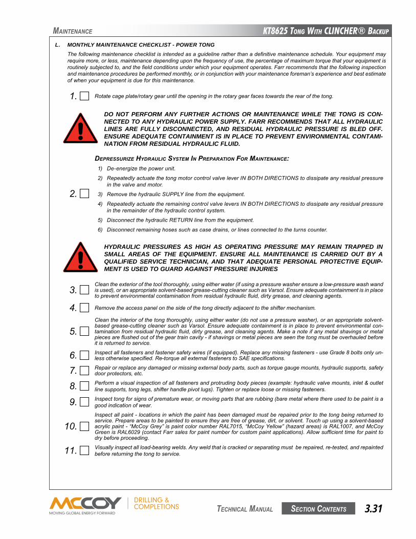
KT8625 Tong WiTh CLinChER® BaCKup
Section contentS 3.31 technical Manual
Maintenance
L. MONTHLY MAINTENANCE CHECKLIST - POWER TONGThefollowingmaintenancechecklistisintendedasaguidelineratherthanadefinitivemaintenanceschedule.Yourequipmentmayrequiremore,orless,maintenancedependinguponthefrequencyofuse,thepercentageofmaximumtorquethatyourequipmentisroutinelysubjectedto,andthefieldconditionsunderwhichyourequipmentoperates.Farrrecommendsthatthefollowinginspectionandmaintenanceproceduresbeperformedmonthly,orinconjunctionwithyourmaintenanceforeman’sexperienceandbestestimateofwhenyourequipmentisdueforthismaintenance.
1. Rotatecageplate/rotarygearuntiltheopeningintherotarygearfacestowardstherearofthetong.
3.Cleantheexteriorofthetoolthoroughly,usingeitherwater(ifusingapressurewasherensurealow-pressurewashwandisused),oranappropriatesolvent-basedgrease-cuttingcleanersuchasVarsol.Ensureadequatecontainmentisinplacetopreventenvironmentalcontaminationfromresidualhydraulicfluid,dirtygrease,andcleaningagents.
4. Removetheaccesspanelonthesideofthetongdirectlyadjacenttotheshiftermechanism.
5.Cleantheinteriorofthetongthoroughly,usingeitherwater(donotuseapressurewasher),oranappropriatesolvent-basedgrease-cuttingcleanersuchasVarsol.Ensureadequatecontainmentisinplacetopreventenvironmentalcon-taminationfromresidualhydraulicfluid,dirtygrease,andcleaningagents.Makeanoteifanymetalshavingsormetalpiecesareflushedoutofthegeartraincavity-ifshavingsormetalpiecesareseenthetongmustbeoverhauledbeforeitisreturnedtoservice.
6. Inspectallfastenersandfastenersafetywires(ifequipped).Replaceanymissingfasteners-useGrade8boltsonlyun-lessotherwisespecified.Re-torqueallexternalfastenerstoSAEspecifications.
7. Repairorreplaceanydamagedormissingexternalbodyparts,suchastorquegaugemounts,hydraulicsupports,safetydoorprotectors,etc.
8. Performavisualinspectionofallfastenersandprotrudingbodypieces(example:hydraulicvalvemounts,inlet&outletlinesupports,tonglegs,shifterhandlepivotlugs).Tightenorreplacelooseormissingfasteners.
9. Inspecttongforsignsofprematurewear,ormovingpartsthatarerubbing(baremetalwherethereusedtobepaintisagoodindicationofwear.
10.Inspectallpaint-locationsinwhichthepainthasbeendamagedmustberepairedpriortothetongbeingreturnedtoservice.Prepareareastobepaintedtoensuretheyarefreeofgrease,dirt,orsolvent.Touchupusingasolvent-basedacrylicpaint-“McCoyGrey”ispaintcolornumberRAL7015,“McCoyYellow”(hazardareas)isRAL1007,andMcCoyGreenisRAL6029(contactFarrsalesforpaintnumberforcustompaintapplications).Allowsufficienttimeforpainttodrybeforeproceeding.
11. Visuallyinspectallload-bearingwelds.Anyweldthatiscrackedorseparatingmustberepaired,re-tested,andrepaintedbeforereturningthetongtoservice.
DO NOT PERFORM ANY FURTHER ACTIONS OR MAINTENANCE WHILE THE TONG IS CON-NECTED TO ANY HYDRAULIC POWER SUPPLY. FARR RECOMMENDS THAT ALL HYDRAULIC LINES ARE FULLY DISCONNECTED, AND RESIDUAL HYDRAULIC PRESSURE IS BLED OFF. ENSURE ADEQUATE CONTAINMENT IS IN PLACE TO PREVENT ENVIRONMENTAL CONTAMI-NATION FROM RESIDUAL HYDRAULIC FLUID.
2.
dEpRESSURIzE HydRAULIC SySTEM IN pREpARATION FOR MAINTENANCE:1) De-energizethepowerunit.
2) RepeatedlyactuatethetongmotorcontrolvalveleverINBOTHDIRECTIONStodissipateanyresidualpressureinthevalveandmotor.
3) RemovethehydraulicSUPPLYlinefromtheequipment.
4) RepeatedlyactuatetheremainingcontrolvalveleversINBOTHDIRECTIONStodissipateanyresidualpressureintheremainderofthehydrauliccontrolsystem.
5) DisconnectthehydraulicRETURNlinefromtheequipment.
6) Disconnectremaininghosessuchascasedrains,orlinesconnectedtotheturnscounter.
HYDRAULIC PRESSURES AS HIGH AS OPERATING PRESSURE MAY REMAIN TRAPPED IN SMALL AREAS OF THE EQUIPMENT. ENSURE ALL MAINTENANCE IS CARRIED OUT BY A QUALIFIED SERVICE TECHNICIAN, AND THAT ADEQUATE PERSONAL PROTECTIVE EQUIP-MENT IS USED TO GUARD AGAINST PRESSURE INJURIES
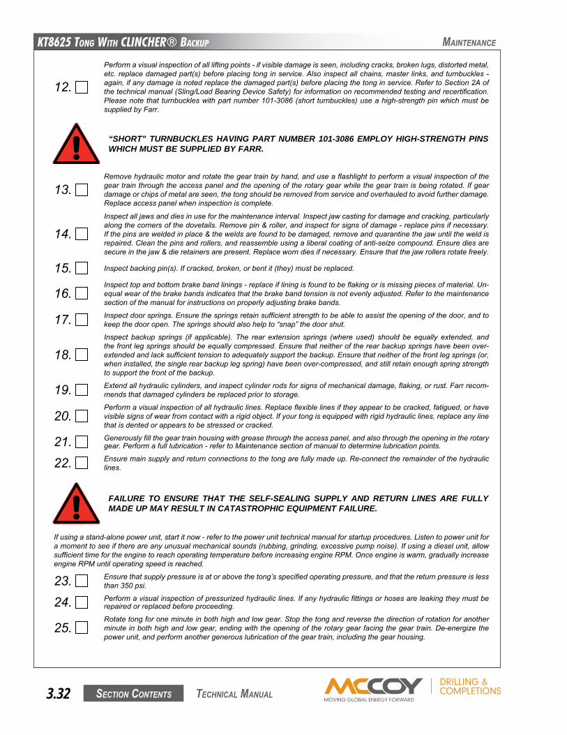
KT8625 Tong WiTh CLinChER® BaCKup
Section contentS3.32 technical Manual
Maintenance
12.
Performavisualinspectionofallliftingpoints-ifvisibledamageisseen,includingcracks,brokenlugs,distortedmetal,etc.replacedamagedpart(s)beforeplacingtonginservice.Alsoinspectallchains,masterlinks,andturnbuckles-again,ifanydamageisnotedreplacethedamagedpart(s)beforeplacingthetonginservice.RefertoSection2Aofthetechnicalmanual(Sling/LoadBearingDeviceSafety)forinformationonrecommendedtestingandrecertification.Pleasenotethatturnbuckleswithpartnumber101-3086(shortturnbuckles)useahigh-strengthpinwhichmustbesuppliedbyFarr.
Ifusingastand-alonepowerunit,startitnow-refertothepowerunittechnicalmanualforstartupprocedures.Listentopowerunitforamomenttoseeifthereareanyunusualmechanicalsounds(rubbing,grinding,excessivepumpnoise).Ifusingadieselunit,allowsufficienttimefortheenginetoreachoperatingtemperaturebeforeincreasingengineRPM.Onceengineiswarm,graduallyincreaseengineRPMuntiloperatingspeedisreached.
23. Ensurethatsupplypressureisatorabovethetong’sspecifiedoperatingpressure,andthatthereturnpressureislessthan350psi.
24. Performavisualinspectionofpressurizedhydrauliclines.Ifanyhydraulicfittingsorhosesareleakingtheymustberepairedorreplacedbeforeproceeding.
25.Rotatetongforoneminuteinbothhighandlowgear.Stopthetongandreversethedirectionofrotationforanotherminuteinbothhighandlowgear,endingwiththeopeningoftherotarygearfacingthegeartrain.De-energizethepowerunit,andperformanothergenerouslubricationofthegeartrain,includingthegearhousing.
FAILURE TO ENSURE THAT THE SELF-SEALING SUPPLY AND RETURN LINES ARE FULLY MADE UP MAY RESULT IN CATASTROPHIC EQUIPMENT FAILURE.
“SHORT” TURNBUCKLES HAVING PART NUMBER 101-3086 EMPLOY HIGH-STRENGTH PINS WHICH MUST BE SUPPLIED BY FARR.
13.Removehydraulicmotorandrotatethegeartrainbyhand,anduseaflashlighttoperformavisualinspectionofthegeartrainthroughtheaccesspanelandtheopeningoftherotarygearwhilethegeartrainisbeingrotated.Ifgeardamageorchipsofmetalareseen,thetongshouldberemovedfromserviceandoverhauledtoavoidfurtherdamage.Replaceaccesspanelwheninspectioniscomplete.
14.Inspectalljawsanddiesinuseforthemaintenanceinterval.Inspectjawcastingfordamageandcracking,particularlyalongthecornersofthedovetails.Removepin&roller,andinspectforsignsofdamage-replacepinsifnecessary.Ifthepinsareweldedinplace&theweldsarefoundtobedamaged,removeandquarantinethejawuntiltheweldisrepaired.Cleanthepinsandrollers,andreassembleusingaliberalcoatingofanti-seizecompound.Ensurediesaresecureinthejaw&dieretainersarepresent.Replaceworndiesifnecessary.Ensurethatthejawrollersrotatefreely.
15. Inspectbackingpin(s).Ifcracked,broken,orbentit(they)mustbereplaced.
16.Inspecttopandbottombrakebandlinings-replaceifliningisfoundtobeflakingorismissingpiecesofmaterial.Un-equalwearofthebrakebandsindicatesthatthebrakebandtensionisnotevenlyadjusted.Refertothemaintenancesectionofthemanualforinstructionsonproperlyadjustingbrakebands.
17. Inspectdoorsprings.Ensurethespringsretainsufficientstrengthtobeabletoassisttheopeningofthedoor,andtokeepthedooropen.Thespringsshouldalsohelpto“snap”thedoorshut.
18.Inspect backup springs (if applicable). The rear extension springs (where used) should be equally extended, andthefrontlegspringsshouldbeequallycompressed.Ensurethatneitheroftherearbackupspringshavebeenover-extendedandlacksufficienttensiontoadequatelysupportthebackup.Ensurethatneitherofthefrontlegsprings(or,wheninstalled,thesinglerearbackuplegspring)havebeenover-compressed,andstillretainenoughspringstrengthtosupportthefrontofthebackup.
19. Extendallhydrauliccylinders,andinspectcylinderrodsforsignsofmechanicaldamage,flaking,orrust.Farrrecom-mendsthatdamagedcylindersbereplacedpriortostorage.
20.Performavisualinspectionofallhydrauliclines.Replaceflexiblelinesiftheyappeartobecracked,fatigued,orhavevisiblesignsofwearfromcontactwitharigidobject.Ifyourtongisequippedwithrigidhydrauliclines,replaceanylinethatisdentedorappearstobestressedorcracked.
21. Generouslyfillthegeartrainhousingwithgreasethroughtheaccesspanel,andalsothroughtheopeningintherotarygear.Performafulllubrication-refertoMaintenancesectionofmanualtodeterminelubricationpoints.
22. Ensuremainsupplyandreturnconnectionstothetongarefullymadeup.Re-connecttheremainderofthehydrauliclines.
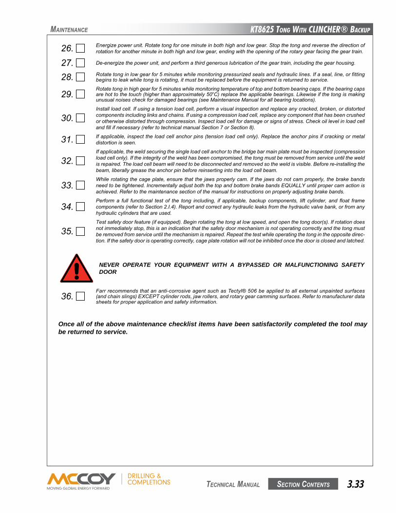
KT8625 Tong WiTh CLinChER® BaCKup
Section contentS 3.33 technical Manual
Maintenance
26. Energizepowerunit.Rotatetongforoneminuteinbothhighandlowgear.Stopthetongandreversethedirectionofrotationforanotherminuteinbothhighandlowgear,endingwiththeopeningoftherotarygearfacingthegeartrain.
27. De-energizethepowerunit,andperformathirdgenerouslubricationofthegeartrain,includingthegearhousing.
28. Rotatetonginlowgearfor5minuteswhilemonitoringpressurizedsealsandhydrauliclines.Ifaseal,line,orfittingbeginstoleakwhiletongisrotating,itmustbereplacedbeforetheequipmentisreturnedtoservice.
29.Rotatetonginhighgearfor5minuteswhilemonitoringtemperatureoftopandbottombearingcaps.Ifthebearingcapsarehottothetouch(higherthanapproximately50oC)replacetheapplicablebearings.Likewiseifthetongismakingunusualnoisescheckfordamagedbearings(seeMaintenanceManualforallbearinglocations).
30.Installloadcell.Ifusingatensionloadcell,performavisualinspectionandreplaceanycracked,broken,ordistortedcomponentsincludinglinksandchains.Ifusingacompressionloadcell,replaceanycomponentthathasbeencrushedorotherwisedistortedthroughcompression.Inspectloadcellfordamageorsignsofstress.Checkoillevelinloadcellandfillifnecessary(refertotechnicalmanualSection7orSection8).
31. Ifapplicable,inspecttheloadcellanchorpins(tensionloadcellonly).Replacetheanchorpinsifcrackingormetaldistortionisseen.
32.Ifapplicable,theweldsecuringthesingleloadcellanchortothebridgebarmainplatemustbeinspected(compressionloadcellonly).Iftheintegrityoftheweldhasbeencompromised,thetongmustberemovedfromserviceuntiltheweldisrepaired.Theloadcellbeamwillneedtobedisconnectedandremovedsotheweldisvisible.Beforere-installingthebeam,liberallygreasetheanchorpinbeforereinsertingintotheloadcellbeam.
33.Whilerotatingthecageplate,ensurethatthejawsproperlycam.If thejawsdonotcamproperly,thebrakebandsneedtobetightened.IncrementallyadjustboththetopandbottombrakebandsEqUALLYuntilpropercamactionisachieved.Refertothemaintenancesectionofthemanualforinstructionsonproperlyadjustingbrakebands.
34.Performa full functional test of the tong including, if applicable, backup components, lift cylinder, and float framecomponents(refertoSection2.I.4).Reportandcorrectanyhydraulicleaksfromthehydraulicvalvebank,orfromanyhydrauliccylindersthatareused.
35.Testsafetydoorfeature(ifequipped).Beginrotatingthetongatlowspeed,andopenthetongdoor(s).Ifrotationdoesnotimmediatelystop,thisisanindicationthatthesafetydoormechanismisnotoperatingcorrectlyandthetongmustberemovedfromserviceuntilthemechanismisrepaired.Repeatthetestwhileoperatingthetongintheoppositedirec-tion.Ifthesafetydoorisoperatingcorrectly,cageplaterotationwillnotbeinhibitedoncethedoorisclosedandlatched.
NEVER OPERATE YOUR EQUIPMENT WITH A BYPASSED OR MALFUNCTIONING SAFETY DOOR
36.Farrrecommendsthatananti-corrosiveagentsuchasTectyl®506beappliedtoallexternalunpaintedsurfaces(andchainslings)EXCEPTcylinderrods,jawrollers,androtarygearcammingsurfaces.Refertomanufacturerdatasheetsforproperapplicationandsafetyinformation.
Once all of the above maintenance checklist items have been satisfactorily completed the tool may be returned to service.
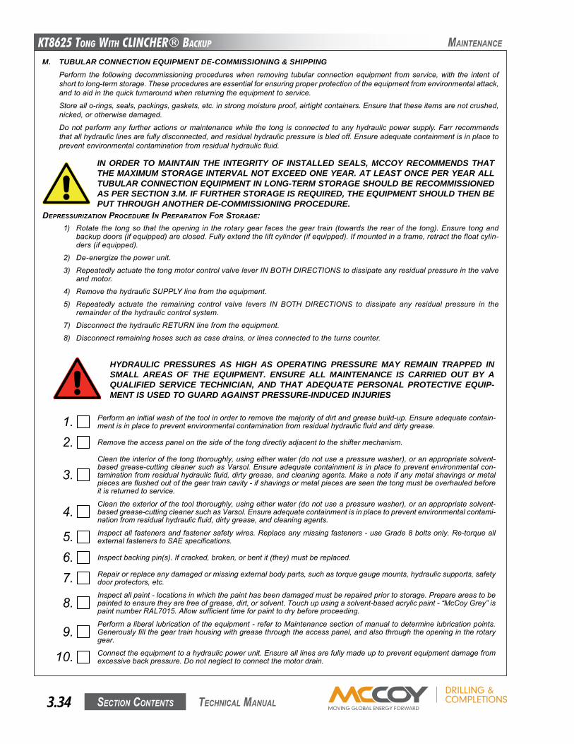
KT8625 Tong WiTh CLinChER® BaCKup
Section contentS3.34 technical Manual
Maintenance
M. TUBULAR CONNECTION EQUIPMENT DE-COMMISSIONING & SHIPPINGPerform the followingdecommissioningprocedureswhen removing tubularconnectionequipment fromservice,with the intentofshorttolong-termstorage.Theseproceduresareessentialforensuringproperprotectionoftheequipmentfromenvironmentalattack,andtoaidinthequickturnaroundwhenreturningtheequipmenttoservice.
Storeallo-rings,seals,packings,gaskets,etc.instrongmoistureproof,airtightcontainers.Ensurethattheseitemsarenotcrushed,nicked,orotherwisedamaged.
Donotperformany furtheractionsormaintenancewhile the tong isconnected toanyhydraulicpowersupply.Farr recommendsthatallhydrauliclinesarefullydisconnected,andresidualhydraulicpressureisbledoff.Ensureadequatecontainmentisinplacetopreventenvironmentalcontaminationfromresidualhydraulicfluid.
1. Performaninitialwashofthetoolinordertoremovethemajorityofdirtandgreasebuild-up.Ensureadequatecontain-mentisinplacetopreventenvironmentalcontaminationfromresidualhydraulicfluidanddirtygrease.
2. Removetheaccesspanelonthesideofthetongdirectlyadjacenttotheshiftermechanism.
3.Cleantheinteriorofthetongthoroughly,usingeitherwater(donotuseapressurewasher),oranappropriatesolvent-basedgrease-cuttingcleanersuchasVarsol.Ensureadequatecontainmentisinplacetopreventenvironmentalcon-taminationfromresidualhydraulicfluid,dirtygrease,andcleaningagents.Makeanoteifanymetalshavingsormetalpiecesareflushedoutofthegeartraincavity-ifshavingsormetalpiecesareseenthetongmustbeoverhauledbeforeitisreturnedtoservice.
4.Cleantheexteriorofthetoolthoroughly,usingeitherwater(donotuseapressurewasher),oranappropriatesolvent-basedgrease-cuttingcleanersuchasVarsol.Ensureadequatecontainmentisinplacetopreventenvironmentalcontami-nationfromresidualhydraulicfluid,dirtygrease,andcleaningagents.
5. Inspectallfastenersandfastenersafetywires.Replaceanymissingfasteners-useGrade8boltsonly.Re-torqueallexternalfastenerstoSAEspecifications.
6. Inspectbackingpin(s).Ifcracked,broken,orbentit(they)mustbereplaced.
7. Repairorreplaceanydamagedormissingexternalbodyparts,suchastorquegaugemounts,hydraulicsupports,safetydoorprotectors,etc.
8.Inspectallpaint-locationsinwhichthepainthasbeendamagedmustberepairedpriortostorage.Prepareareastobepaintedtoensuretheyarefreeofgrease,dirt,orsolvent.Touchupusingasolvent-basedacrylicpaint-“McCoyGrey”ispaintnumberRAL7015.Allowsufficienttimeforpainttodrybeforeproceeding.
9.Performaliberallubricationoftheequipment-refertoMaintenancesectionofmanualtodeterminelubricationpoints.Generouslyfillthegeartrainhousingwithgreasethroughtheaccesspanel,andalsothroughtheopeningintherotarygear.
10. Connecttheequipmenttoahydraulicpowerunit.Ensurealllinesarefullymadeuptopreventequipmentdamagefromexcessivebackpressure.Donotneglecttoconnectthemotordrain.
HYDRAULIC PRESSURES AS HIGH AS OPERATING PRESSURE MAY REMAIN TRAPPED IN SMALL AREAS OF THE EQUIPMENT. ENSURE ALL MAINTENANCE IS CARRIED OUT BY A QUALIFIED SERVICE TECHNICIAN, AND THAT ADEQUATE PERSONAL PROTECTIVE EQUIP-MENT IS USED TO GUARD AGAINST PRESSURE-INDUCED INJURIES
dEpRESSURIzATION pROCEdURE IN pREpARATION FOR STORAgE:1) Rotatethetongsothat theopening in therotarygear facesthegeartrain(towardstherearof thetong).Ensuretongand
backupdoors(ifequipped)areclosed.Fullyextendtheliftcylinder(ifequipped).Ifmountedinaframe,retractthefloatcylin-ders(ifequipped).
2) De-energizethepowerunit.
3) RepeatedlyactuatethetongmotorcontrolvalveleverINBOTHDIRECTIONStodissipateanyresidualpressureinthevalveandmotor.
4) RemovethehydraulicSUPPLYlinefromtheequipment.
5) Repeatedly actuate the remaining control valve levers IN BOTH DIRECTIONS to dissipate any residual pressure in theremainderofthehydrauliccontrolsystem.
7) DisconnectthehydraulicRETURNlinefromtheequipment.
8) Disconnectremaininghosessuchascasedrains,orlinesconnectedtotheturnscounter.
IN ORDER TO MAINTAIN THE INTEGRITY OF INSTALLED SEALS, MCCOY RECOMMENDS THAT THE MAXIMUM STORAGE INTERVAL NOT EXCEED ONE YEAR. AT LEAST ONCE PER YEAR ALL TUBULAR CONNECTION EQUIPMENT IN LONG-TERM STORAGE SHOULD BE RECOMMISSIONED AS PER SECTION 3.M. IF FURTHER STORAGE IS REQUIRED, THE EQUIPMENT SHOULD THEN BE PUT THROUGH ANOTHER DE-COMMISSIONING PROCEDURE.
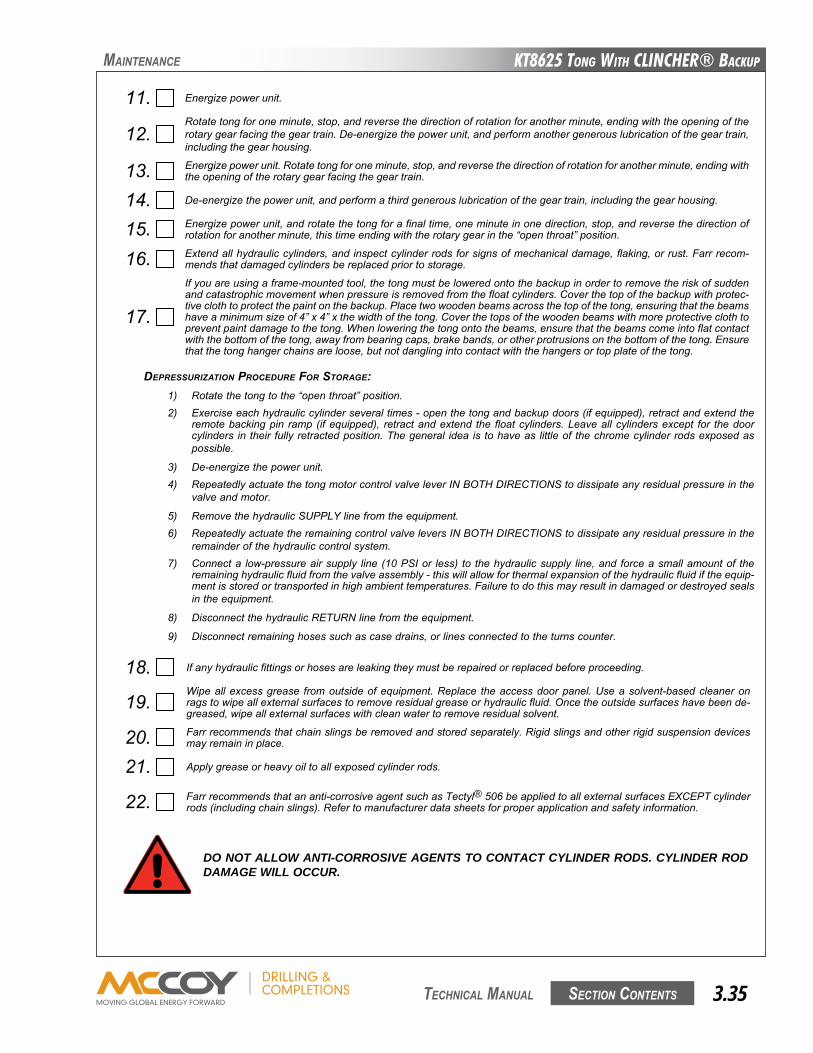
KT8625 Tong WiTh CLinChER® BaCKup
Section contentS 3.35 technical Manual
Maintenance
dEpRESSURIzATION pROCEdURE FOR STORAgE:1) Rotatethetongtothe“openthroat”position.2) Exerciseeachhydrauliccylinderseveraltimes-openthetongandbackupdoors(ifequipped),retractandextendthe
remotebackingpin ramp(ifequipped), retractandextend the floatcylinders.Leaveallcylindersexcept for thedoorcylinders in their fullyretractedposition.Thegeneral idea is tohaveas littleof thechromecylinderrodsexposedaspossible.
3) De-energizethepowerunit.4) RepeatedlyactuatethetongmotorcontrolvalveleverINBOTHDIRECTIONStodissipateanyresidualpressureinthe
valveandmotor.
5) RemovethehydraulicSUPPLYlinefromtheequipment.6) RepeatedlyactuatetheremainingcontrolvalveleversINBOTHDIRECTIONStodissipateanyresidualpressureinthe
remainderofthehydrauliccontrolsystem.7) Connecta low-pressureairsupply line(10PSIor less) to thehydraulicsupply line,andforceasmallamountof the
remaininghydraulicfluidfromthevalveassembly-thiswillallowforthermalexpansionofthehydraulicfluidiftheequip-mentisstoredortransportedinhighambienttemperatures.Failuretodothismayresultindamagedordestroyedsealsintheequipment.
8) DisconnectthehydraulicRETURNlinefromtheequipment.
9) Disconnectremaininghosessuchascasedrains,orlinesconnectedtotheturnscounter.
11. Energizepowerunit.
12.Rotatetongforoneminute,stop,andreversethedirectionofrotationforanotherminute,endingwiththeopeningoftherotarygearfacingthegeartrain.De-energizethepowerunit,andperformanothergenerouslubricationofthegeartrain,includingthegearhousing.
13. Energizepowerunit.Rotatetongforoneminute,stop,andreversethedirectionofrotationforanotherminute,endingwiththeopeningoftherotarygearfacingthegeartrain.
14. De-energizethepowerunit,andperformathirdgenerouslubricationofthegeartrain,includingthegearhousing.
15. Energizepowerunit,androtatethetongforafinaltime,oneminuteinonedirection,stop,andreversethedirectionofrotationforanotherminute,thistimeendingwiththerotarygearinthe“openthroat”position.
16. Extendallhydrauliccylinders,andinspectcylinderrodsforsignsofmechanicaldamage,flaking,orrust.Farrrecom-mendsthatdamagedcylindersbereplacedpriortostorage.
17.
Ifyouareusingaframe-mountedtool,thetongmustbeloweredontothebackupinordertoremovetheriskofsuddenandcatastrophicmovementwhenpressureisremovedfromthefloatcylinders.Coverthetopofthebackupwithprotec-tiveclothtoprotectthepaintonthebackup.Placetwowoodenbeamsacrossthetopofthetong,ensuringthatthebeamshaveaminimumsizeof4”x4”xthewidthofthetong.Coverthetopsofthewoodenbeamswithmoreprotectiveclothtopreventpaintdamagetothetong.Whenloweringthetongontothebeams,ensurethatthebeamscomeintoflatcontactwiththebottomofthetong,awayfrombearingcaps,brakebands,orotherprotrusionsonthebottomofthetong.Ensurethatthetonghangerchainsareloose,butnotdanglingintocontactwiththehangersortopplateofthetong.
18. Ifanyhydraulicfittingsorhosesareleakingtheymustberepairedorreplacedbeforeproceeding.
19.Wipeallexcessgrease fromoutsideofequipment.Replace theaccessdoorpanel.Useasolvent-basedcleaneronragstowipeallexternalsurfacestoremoveresidualgreaseorhydraulicfluid.Oncetheoutsidesurfaceshavebeende-greased,wipeallexternalsurfaceswithcleanwatertoremoveresidualsolvent.
20. Farrrecommendsthatchainslingsberemovedandstoredseparately.Rigidslingsandotherrigidsuspensiondevicesmayremaininplace.
21. Applygreaseorheavyoiltoallexposedcylinderrods.
22. Farrrecommendsthatananti-corrosiveagentsuchasTectyl®506beappliedtoallexternalsurfacesEXCEPTcylinderrods(includingchainslings).Refertomanufacturerdatasheetsforproperapplicationandsafetyinformation.
DO NOT ALLOW ANTI-CORROSIVE AGENTS TO CONTACT CYLINDER RODS. CYLINDER ROD DAMAGE WILL OCCUR.
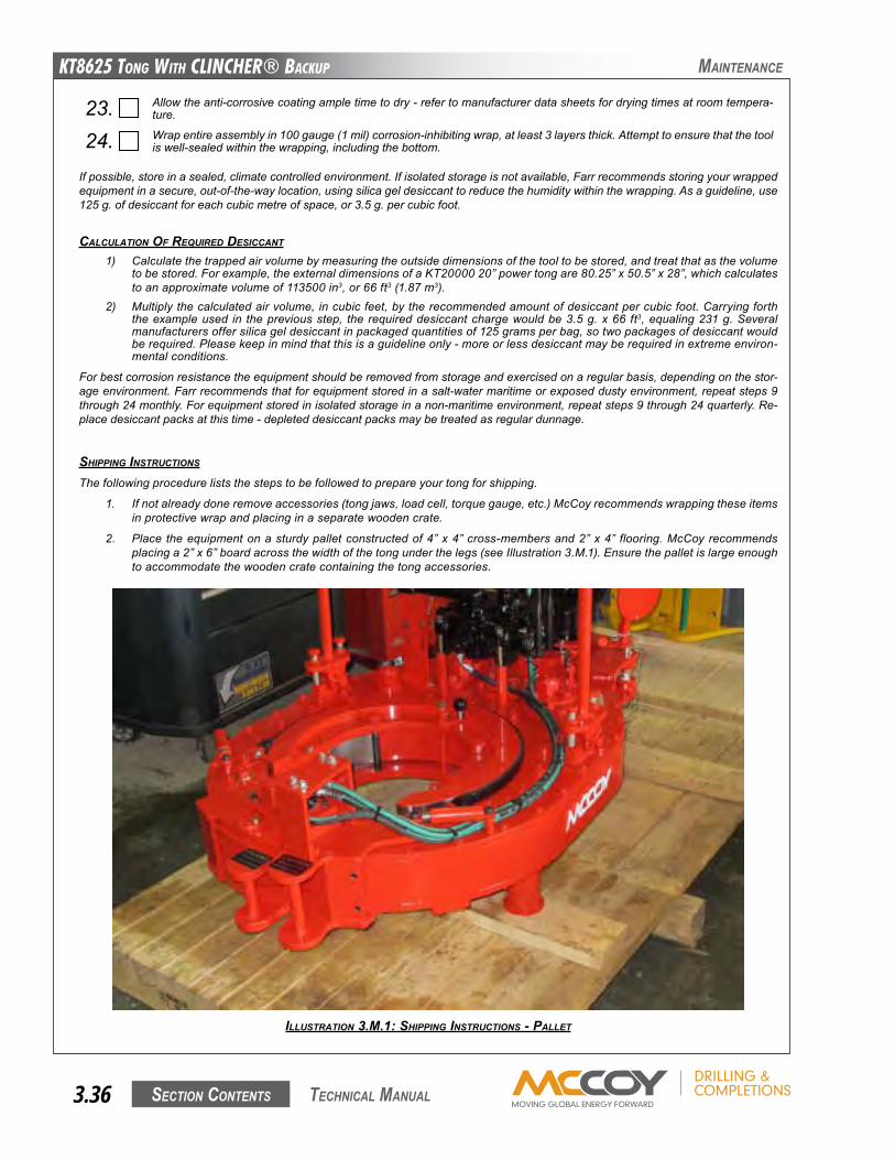
KT8625 Tong WiTh CLinChER® BaCKup
Section contentS3.36 technical Manual
Ifpossible,storeinasealed,climatecontrolledenvironment.Ifisolatedstorageisnotavailable,Farrrecommendsstoringyourwrappedequipmentinasecure,out-of-the-waylocation,usingsilicageldesiccanttoreducethehumiditywithinthewrapping.Asaguideline,use125g.ofdesiccantforeachcubicmetreofspace,or3.5g.percubicfoot.
CALCULATION OF REqUIREd dESICCANT
1) Calculatethetrappedairvolumebymeasuringtheoutsidedimensionsofthetooltobestored,andtreatthatasthevolumetobestored.Forexample,theexternaldimensionsofaKT2000020”powertongare80.25”x50.5”x28”,whichcalculatestoanapproximatevolumeof113500in3,or66ft3(1.87m3).
2) Multiplythecalculatedairvolume,incubicfeet,bytherecommendedamountofdesiccantpercubicfoot.Carryingforththeexampleused in thepreviousstep, the requireddesiccantchargewouldbe3.5g.x66 ft3,equaling231g.Severalmanufacturersoffersilicageldesiccantinpackagedquantitiesof125gramsperbag,sotwopackagesofdesiccantwouldberequired.Pleasekeepinmindthatthisisaguidelineonly-moreorlessdesiccantmayberequiredinextremeenviron-mentalconditions.
Forbestcorrosionresistancetheequipmentshouldberemovedfromstorageandexercisedonaregularbasis,dependingonthestor-ageenvironment.Farrrecommendsthatforequipmentstoredinasalt-watermaritimeorexposeddustyenvironment,repeatsteps9through24monthly.Forequipmentstoredinisolatedstorageinanon-maritimeenvironment,repeatsteps9through24quarterly.Re-placedesiccantpacksatthistime-depleteddesiccantpacksmaybetreatedasregulardunnage.
SHIppINg INSTRUCTIONS
Thefollowingprocedureliststhestepstobefollowedtoprepareyourtongforshipping.
1. Ifnotalreadydoneremoveaccessories(tongjaws,loadcell,torquegauge,etc.)McCoyrecommendswrappingtheseitemsinprotectivewrapandplacinginaseparatewoodencrate.
2. Place theequipmentonasturdypalletconstructedof4”x4”cross-membersand2”x4” flooring.McCoyrecommendsplacinga2”x6”boardacrossthewidthofthetongunderthelegs(seeIllustration3.M.1).Ensurethepalletislargeenoughtoaccommodatethewoodencratecontainingthetongaccessories.
23. Allowtheanti-corrosivecoatingampletimetodry-refertomanufacturerdatasheetsfordryingtimesatroomtempera-ture.
24. Wrapentireassemblyin100gauge(1mil)corrosion-inhibitingwrap,atleast3layersthick.Attempttoensurethatthetooliswell-sealedwithinthewrapping,includingthebottom.
Maintenance
ILLUSTRATION 3.M.1: SHIppINg INSTRUCTIONS - pALLET
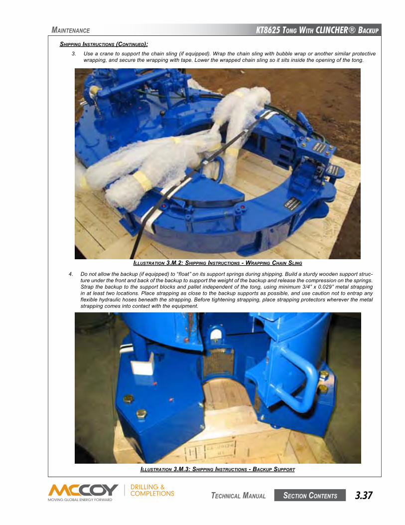
KT8625 Tong WiTh CLinChER® BaCKup
Section contentS 3.37 technical Manual
Maintenance
SHIppINg INSTRUCTIONS (CONTINUEd):3. Useacranetosupportthechainsling(ifequipped).Wrapthechainslingwithbubblewraporanothersimilarprotective
wrapping,andsecurethewrappingwithtape.Lowerthewrappedchainslingsoitsitsinsidetheopeningofthetong.
ILLUSTRATION 3.M.2: SHIppINg INSTRUCTIONS - wRAppINg CHAIN SLINg
4. Donotallowthebackup(ifequipped)to“float”onitssupportspringsduringshipping.Buildasturdywoodensupportstruc-tureunderthefrontandbackofthebackuptosupporttheweightofthebackupandreleasethecompressiononthesprings.Strapthebackuptothesupportblocksandpalletindependentofthetong,usingminimum3/4”x0.029”metalstrappinginatleasttwolocations.Placestrappingasclosetothebackupsupportsaspossible,andusecautionnottoentrapanyflexiblehydraulichosesbeneaththestrapping.Beforetighteningstrapping,placestrappingprotectorswhereverthemetalstrappingcomesintocontactwiththeequipment.
ILLUSTRATION 3.M.3: SHIppINg INSTRUCTIONS - BACKUp SUppORT
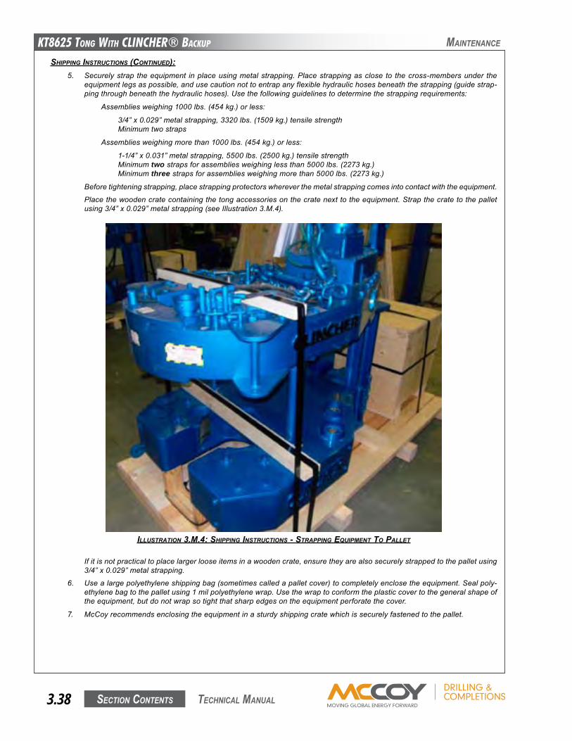
KT8625 Tong WiTh CLinChER® BaCKup
Section contentS3.38 technical Manual
Maintenance
SHIppINg INSTRUCTIONS (CONTINUEd):5. Securelystrap theequipment inplaceusingmetalstrapping.Placestrappingasclose to thecross-membersunder the
equipmentlegsaspossible,andusecautionnottoentrapanyflexiblehydraulichosesbeneaththestrapping(guidestrap-pingthroughbeneaththehydraulichoses).Usethefollowingguidelinestodeterminethestrappingrequirements:
Assembliesweighing1000lbs.(454kg.)orless:
3/4”x0.029”metalstrapping,3320lbs.(1509kg.)tensilestrength Minimumtwostraps
Assembliesweighingmorethan1000lbs.(454kg.)orless:
1-1/4”x0.031”metalstrapping,5500lbs.(2500kg.)tensilestrength Minimumtwostrapsforassembliesweighinglessthan5000lbs.(2273kg.) Minimumthreestrapsforassembliesweighingmorethan5000lbs.(2273kg.)
Beforetighteningstrapping,placestrappingprotectorswhereverthemetalstrappingcomesintocontactwiththeequipment.
Placethewoodencratecontainingthetongaccessoriesonthecratenexttotheequipment.Strapthecratetothepalletusing3/4”x0.029”metalstrapping(seeIllustration3.M.4).
Ifitisnotpracticaltoplacelargerlooseitemsinawoodencrate,ensuretheyarealsosecurelystrappedtothepalletusing3/4”x0.029”metalstrapping.
6. Usealargepolyethyleneshippingbag(sometimescalledapalletcover)tocompletelyenclosetheequipment.Sealpoly-ethylenebagtothepalletusing1milpolyethylenewrap.Usethewraptoconformtheplasticcovertothegeneralshapeoftheequipment,butdonotwrapsotightthatsharpedgesontheequipmentperforatethecover.
7. McCoyrecommendsenclosingtheequipmentinasturdyshippingcratewhichissecurelyfastenedtothepallet.
ILLUSTRATION 3.M.4: SHIppINg INSTRUCTIONS - STRAppINg EqUIpMENT TO pALLET
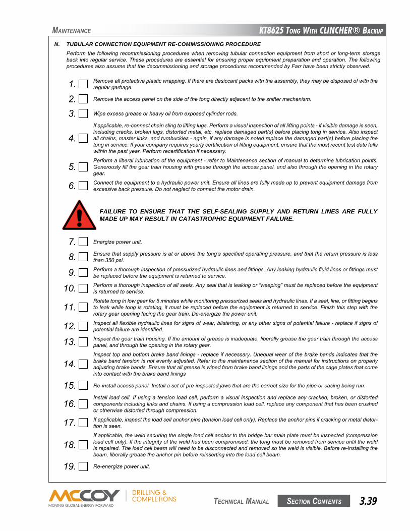
KT8625 Tong WiTh CLinChER® BaCKup
Section contentS 3.39 technical Manual
N. TUBULAR CONNECTION EQUIPMENT RE-COMMISSIONING PROCEDUREPerform the following recommissioningprocedureswhenremoving tubularconnectionequipment fromshortor long-termstoragebackintoregularservice.Theseproceduresareessentialforensuringproperequipmentpreparationandoperation.ThefollowingproceduresalsoassumethatthedecommissioningandstorageproceduresrecommendedbyFarrhavebeenstrictlyobserved.
7. Energizepowerunit.
8. Ensurethatsupplypressureisatorabovethetong’sspecifiedoperatingpressure,andthatthereturnpressureislessthan350psi.
9. Performathoroughinspectionofpressurizedhydrauliclinesandfittings.Anyleakinghydraulicfluidlinesorfittingsmustbereplacedbeforetheequipmentisreturnedtoservice.
10. Performathoroughinspectionofallseals.Anysealthatisleakingor“weeping”mustbereplacedbeforetheequipmentisreturnedtoservice.
11.Rotatetonginlowgearfor5minuteswhilemonitoringpressurizedsealsandhydrauliclines.Ifaseal,line,orfittingbeginstoleakwhiletongisrotating,itmustbereplacedbeforetheequipmentisreturnedtoservice.Finishthisstepwiththerotarygearopeningfacingthegeartrain.De-energizethepowerunit.
12. Inspectallflexiblehydrauliclinesforsignsofwear,blistering,oranyothersignsofpotentialfailure-replaceifsignsofpotentialfailureareidentified.
13. Inspectthegeartrainhousing.Iftheamountofgreaseisinadequate,liberallygreasethegeartrainthroughtheaccesspanel,andthroughtheopeningintherotarygear.
14.Inspecttopandbottombrakebandlinings-replaceifnecessary.Unequalwearofthebrakebandsindicatesthatthebrakebandtensionisnotevenlyadjusted.Refertothemaintenancesectionofthemanualforinstructionsonproperlyadjustingbrakebands.Ensurethatallgreaseiswipedfrombrakebandliningsandthepartsofthecageplatesthatcomeintocontactwiththebrakebandlinings
15. Re-installaccesspanel.Installasetofpre-inspectedjawsthatarethecorrectsizeforthepipeorcasingbeingrun.
16.Install loadcell.Ifusingatensionloadcell,performavisual inspectionandreplaceanycracked,broken,ordistortedcomponentsincludinglinksandchains.Ifusingacompressionloadcell,replaceanycomponentthathasbeencrushedorotherwisedistortedthroughcompression.
17. Ifapplicable,inspecttheloadcellanchorpins(tensionloadcellonly).Replacetheanchorpinsifcrackingormetaldistor-tionisseen.
18.Ifapplicable,theweldsecuringthesingleloadcellanchortothebridgebarmainplatemustbeinspected(compressionloadcellonly).Iftheintegrityoftheweldhasbeencompromised,thetongmustberemovedfromserviceuntiltheweldisrepaired.Theloadcellbeamwillneedtobedisconnectedandremovedsotheweldisvisible.Beforere-installingthebeam,liberallygreasetheanchorpinbeforereinsertingintotheloadcellbeam.
19. Re-energizepowerunit.
FAILURE TO ENSURE THAT THE SELF-SEALING SUPPLY AND RETURN LINES ARE FULLY MADE UP MAY RESULT IN CATASTROPHIC EQUIPMENT FAILURE.
1. Removeallprotectiveplasticwrapping.Iftherearedesiccantpackswiththeassembly,theymaybedisposedofwiththeregulargarbage.
2. Removetheaccesspanelonthesideofthetongdirectlyadjacenttotheshiftermechanism.
3. Wipeexcessgreaseorheavyoilfromexposedcylinderrods.
4.Ifapplicable,re-connectchainslingtoliftinglugs.Performavisualinspectionofallliftingpoints-ifvisibledamageisseen,includingcracks,brokenlugs,distortedmetal,etc.replacedamagedpart(s)beforeplacingtonginservice.Alsoinspectallchains,masterlinks,andturnbuckles-again,ifanydamageisnotedreplacethedamagedpart(s)beforeplacingthetonginservice.Ifyourcompanyrequiresyearlycertificationofliftingequipment,ensurethatthemostrecenttestdatefallswithinthepastyear.Performrecertificationifnecessary.
5.Performaliberallubricationoftheequipment-refertoMaintenancesectionofmanualtodeterminelubricationpoints.Generouslyfillthegeartrainhousingwithgreasethroughtheaccesspanel,andalsothroughtheopeningintherotarygear.
6. Connecttheequipmenttoahydraulicpowerunit.Ensurealllinesarefullymadeuptopreventequipmentdamagefromexcessivebackpressure.Donotneglecttoconnectthemotordrain.
Maintenance
KT8625 Tong WiTh CLinChER® BaCKup
Section contentS3.40 technical Manual
Maintenance
20. Performafullfunctionaltestoftheequipmentincluding,ifapplicable,backupcomponentsandfloatframecomponents.Reportandcorrectanyhydraulicleaksfromthehydraulicvalvebank,orfromanyhydrauliccylindersthatareused.
21.Ifusingaframe-mountedtongandbackupsystem,raisethetongoffthebeamsthatitisrestingupon.Removethebeamsandprotectivecloths-inspectthepaintontopofthebackupandthebottomofthetongtoensureithasnotbeendam-agedbythebeam.
22.Testsafetydoorfeature(ifequipped).Openthetongdoor(s),andattempttorotatethecageplateatlowspeed(lowgear)inbothdirections(makeupandbreakout).Ifcageplatebeginsrotating,thesafetydoormechanismisnotfunctional,andthetongmustberemovedfromserviceuntilthesafetydoormechanismcanberepaired.Ifthesafetydoorisoperatingcorrectly,cageplaterotationwillnotbeinhibitedoncethedoorisclosedandlatched.
NEVER OPERATE YOUR EQUIPMENT WITH A BYPASSED OR MALFUNCTIONING SAFETY DOOR
23.Whilerotatingthecageplate,ensurethatthejawsproperlycam.Ifthejawsdonotcamproperly,thebrakebandsneedtobetightened.IncrementallyadjustboththetopandbottombrakebandsEqUALLYuntilpropercamactionisachieved.
24. Whenallofthepreviousstepsarecompleted,youmayreturnyourre-commissionedequipmenttoservice.
KT8625 Tong WiTh CLinChER® BaCKup
Section contentS 4.1 technical Manual
tRouBleShootinG
Adequatemaintenanceandproperfluidselectionisessentialforminimizinghydraulic-relatedfailures.Alltroubleshootingmustbeper-formedbyatechniciantrainedinhydraulicsystems,andfamiliarwiththeequipmentdesign,assemblyandoperation.
Thefollowingtroubleshootinginstructionsareintendedtobeguidelinesonly.Anyfaultsnotsolvedthroughtheuseofthisguideshouldbereferredtoourengineeringdepartmentfortheirevaluationandrecommendations.
A. TONG WILL NOT DEVELOP SUFFICIENT TORQUE1. Malfunctioningreliefvalveontonghydrauliccircuit.
SeeSection4.B,ReliefValveTroubleshooting
2. POSSIBLEPROBLEM:Directionalvalveisleaking.
SOLUTION:Checkdirectionalvalve.Neutralpositionshouldreturnfluiddirectlytothereservoir.Replaceorrepairvalvetoensurecorrectoperation.
3. POSSIBLEPROBLEM:Powerunitisnotproducingadequatepressure.
SOLUTION:Troubleshootpowerunit(seeuser’smanualforyourparticularunit).
4. POSSIBLEPROBLEM:Poorhydraulicpressureatthetongdespiteadequatepressureatthepowerunit,orexcessivebackpressureinthereturnline.
SOLUTION:Restrictionsexistinlinebetweenpowerunitandtong.Inspectintegrityofself-sealingcouplingstoensuretheyareallowingfullfluidflow.Checktoensurenootherrestrictionsexist(contaminatedcatchscreensorfilters,forexample).
5. POSSIBLEPROBLEM:Fluidviscosityisnotappropriate(toohighortoolow).
SOLUTION:EnsurehydraulicfluidbeingusedistheviscosityrecommendedbyMcCoyDrilling&Completions.Powerunitpumpmaynotprimeiffluidistooheavy,andthehydraulicsystemwilloverheatiffluidistoolight.Replacewithproperviscosityfluid.
SOLUTION:Hydraulicfluidviscosityisaffectedbyenvironmentalconditions.Ensurethefluidbeingusedissuitableforhighorlowtemperatures.Replacewithproperviscosityfluidfortheoperatingconditionsifnecessary.
6. POSSIBLEPROBLEM:Wornordamagedtongmotorcausingslippage.
SOLUTION:Replaceorrepairwornordamagedmotor.
7. POSSIBLEPROBLEM:Damagedbearingsorgearscausingexcessivedrag.
SOLUTION:Replaceorrepairwornordamagedgearsorbearings.
8. POSSIBLEPROBLEM:Jawsslippingonpipe.
SOLUTION:Ensurejawdiesarenotworntothepointthattheycannotgrip.Ensurethecorrectsizedjawsareinuse.
9. POSSIBLEPROBLEM:Torquegaugeisindicatingincorrectly
SOLUTION:Incorrectgaugeisbeingused.Ensuregaugeistheproperrange,andhasbeenproperlycalibratedforthearmlengthoftheequipmentinuse.
SOLUTION:Gaugehasbeendamaged.Checkgaugeoperationandcalibrationonindependentsystem.
SOLUTION:Gaugehasmistakenlybeenmarriedtoanincorrectloadcell.
10. POSSIBLEPROBLEM:Loadcellismeasuringincorrectly.
SOLUTION:Incorrectloadcellisbeingused.
SOLUTION:Airistrappedintorquemeasuringcircuit(loadcell,hydraulicline,orgauge.Refertotorquemeasurementtrouble-shootinginSection6ofthismanual.
SOLUTION:Loadcellhasbeendamaged.Replaceloadcell,orreturntoMcCoyforrepairandre-calibration.
MCCOY DRILLING & COMPLETIONS GUARANTEES CALIBRATION OF A LOAD CELL/TORQUE GAUGE ASSEMBLY FOR A PERIOD OF ONE YEAR. MCCOY SUGGESTS THAT THE LOAD CELL/TORQUE GAUGE ASSEMBLY BE RETURNED TO THE FACTORY FOR RE-CALIBRATION ON A YEARLY BASIS.
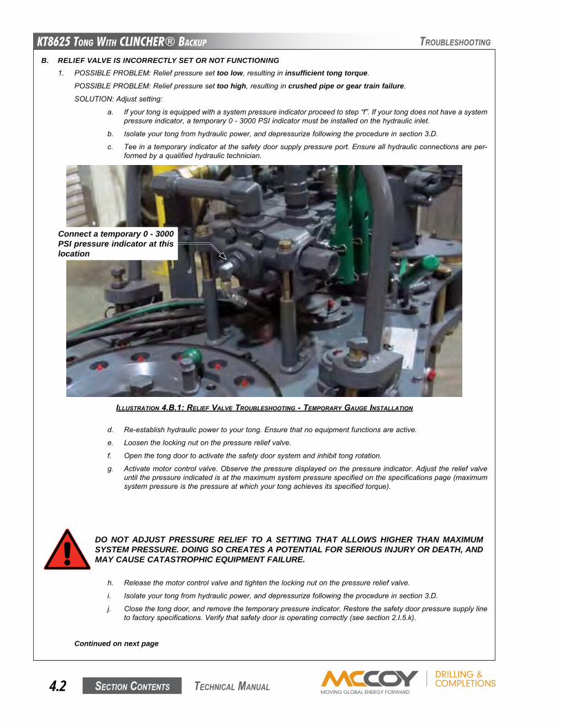
KT8625 Tong WiTh CLinChER® BaCKup
Section contentS4.2 technical Manual
tRouBleShootinG
B. RELIEF VALVE IS INCORRECTLY SET OR NOT FUNCTIONING1. POSSIBLEPROBLEM:Reliefpressuresettoo low,resultingininsufficient tong torque.
POSSIBLEPROBLEM:Reliefpressuresettoo high,resultingincrushed pipe or gear train failure.
SOLUTION:Adjustsetting:
a. Ifyourtongisequippedwithasystempressureindicatorproceedtostep“f”.Ifyourtongdoesnothaveasystempressureindicator,atemporary0-3000PSIindicatormustbeinstalledonthehydraulicinlet.
b. Isolateyourtongfromhydraulicpower,anddepressurizefollowingtheprocedureinsection3.D.
c. Teeinatemporaryindicatoratthesafetydoorsupplypressureport.Ensureallhydraulicconnectionsareper-formedbyaqualifiedhydraulictechnician.
d. Re-establishhydraulicpowertoyourtong.Ensurethatnoequipmentfunctionsareactive.
e. Loosenthelockingnutonthepressurereliefvalve.
f. Openthetongdoortoactivatethesafetydoorsystemandinhibittongrotation.
g. Activatemotorcontrolvalve.Observethepressuredisplayedonthepressureindicator.Adjustthereliefvalveuntilthepressureindicatedisatthemaximumsystempressurespecifiedonthespecificationspage(maximumsystempressureisthepressureatwhichyourtongachievesitsspecifiedtorque).
DO NOT ADJUST PRESSURE RELIEF TO A SETTING THAT ALLOWS HIGHER THAN MAXIMUM SYSTEM PRESSURE. DOING SO CREATES A POTENTIAL FOR SERIOUS INJURY OR DEATH, AND MAY CAUSE CATASTROPHIC EQUIPMENT FAILURE.
h. Releasethemotorcontrolvalveandtightenthelockingnutonthepressurereliefvalve.
i. Isolateyourtongfromhydraulicpower,anddepressurizefollowingtheprocedureinsection3.D.
j. Closethetongdoor,andremovethetemporarypressureindicator.Restorethesafetydoorpressuresupplylinetofactoryspecifications.Verifythatsafetydoorisoperatingcorrectly(seesection2.I.5.k).
Continued on next page
ILLUSTRATION 4.B.1: RELIEF vALvE TROUBLESHOOTINg - TEMpORARy gAUgE INSTALLATION
Connect a temporary 0 - 3000 PSI pressure indicator at this location

KT8625 Tong WiTh CLinChER® BaCKup
Section contentS 4.3 technical Manual
tRouBleShootinG
RELIEF VALVE IS INCORRECTLY SET OR NOT FUNCTIONING Cont’d:2. POSSIBLEPROBLEM:Reliefcannotbeadjustedtomaximumsystempressure(highfluidbypassresultsinlowsystempres-
sure).
SOLUTION:Debrisonvalveseat,springisbroken,springhaslostspringforceduetocontinuoustension
a. Isolateyourtongfromhydraulicpower,anddepressurizefollowingtheprocedureinsection3.D.
b. Loosenthelockingnutonthepressurereliefvalve.
c. Usealargeflat-headscrewdrivertocompletelyun-threadthepoppetandspringfromthereliefassembly.
d. Inspectthereliefvalvespring,poppet,andvalveseat.
e. Ifnodebrisisfoundinreliefvalveandifseatandpoppetareundamaged,replacereliefvalvespring.
f. Reassemblereliefvalve.
g. Reliefvalvemustbere-settoallowmaximumsystempressure.FollowtheprocedureinStep1ofthissectiontoproperlyadjustreliefvalve.
h. Ifmaximumsystempressurestillcannotbereached,replacetheentirereliefvalveassembly.
KT8625 Tong WiTh CLinChER® BaCKup
Section contentS4.4 technical Manual
tRouBleShootinG
C. SAFETY DOOR DOES NOT OPERATE OR IS MALFUNCTIONING
1. POSSIBLEPROBLEM:Safetydoorswitchrequiresadjustment.
SOLUTION:Adjustswitchaspersection3.F.4.
2. POSSIBLEPROBLEM:Safetydoorswitchhasfailed.
SOLUTION:Testsafetydoorswitchforproperfunctionandreplaceifnecessary.
3. POSSIBLEPROBLEM:Contaminationinhydrauliclines.
SOLUTION:Ensureallthreeflexiblehydrauliclinestosafetydoorswitcharefree-flowing.
4. POSSIBLEPROBLEM:Pilot-to-openvalveinsafetydoorvalveblockismalfunctioning.
SOLUTION: Removeeachvalve.Inspectseatsandsprings.Replacevalve(s)ifdamageisseenonvalveseats,orifspringappearstobedamagedorbroken.

KT8625 Tong WiTh CLinChER® BaCKup
Section contentS 4.5 technical Manual
tRouBleShootinG
D. TONG RUNNING TOO SLOWLY
1. POSSIBLEPROBLEM:Obstructionintonghydrauliccircuitpreventingadequateflow.
SOLUTION:Inspectself-sealingcouplingstoensuretheyareproperlyengaged.
SOLUTION:Themainhydrauliclines(supplyanddischarge)tothetongareobstructed.Removeandcleanifrequired.
2. POSSIBLEPROBLEM:Powerunitisnotproducingadequatefloworpressure.
SOLUTION:Troubleshootpowerunit(seeuser’smanualforyourparticularunit).
3. POSSIBLEPROBLEM:Tongmotorisexcessivelywornandisleakinghydraulicfluidpastthevanes.
SOLUTION:Replacemotor,orrebuildasperSection7ofthismanual.
4. POSSIBLEPROBLEM:Bearingsingeartrainandrotarysectionareexcessivelyworn.
SOLUTION:Overhaultong.SeeSection3ofthismanualfortongoverhaulprocedures.
5. POSSIBLEPROBLEM:Shifterhasmalfunctionedandthetongisnotshiftingtohighgear.
SOLUTION:Inspectandrepairshiftmechanismasnecessary.
6. POSSIBLEPROBLEM:Two-speedhydraulicmotor(ifequipped)isnotsettocorrectspeed.
SOLUTION:Checkmotor,andsettothecorrectspeedifrequired.
7. POSSIBLEPROBLEM:Safetydoorsystemisnotproperlyadjusted-hydraulicfluidleakpastDeltrolvalve.
SOLUTION:Checkandadjustsafetydoorsystem.
8. POSSIBLEPROBLEM:Hydraulicfluidviscositytoohigh.
SOLUTION:EnsurehydraulicfluidmeetsMcCoyDrilling&Completionsspecifications.
SOLUTION:Ensurehydraulicfluidisappropriateforclimaticconditions,especiallyduringcold-weatheroperation..
9. POSSIBLEPROBLEM:By-passvalvenotfunctioning.
SOLUTION:Checkandrepair.
KT8625 Tong WiTh CLinChER® BaCKup
Section contentS4.6 technical Manual
tRouBleShootinG
E. FAILURE OF JAWS TO GRIP PIPE
1. POSSIBLEPROBLEM:Dieshavebecometoodulltoprovideadequategrip.
SOLUTION:Replacedies.
2. POSSIBLEPROBLEM:Incorrectjawsarebeingused.
SOLUTION:Double-checkjawsizetoensuretheyareratedforthediameterofpipeorcasingbeingrun.
3. POSSIBLEPROBLEM:Incorrectdiesarebeingused
SOLUTION:Ensurediesloadedinthejawsareappropriateforthetypeofpipeorcasingbeingrun.
4. POSSIBLEPROBLEM:Brakeband(s)is(are)insufficientlyadjusted,notallowingjawstocamproperly.
SOLUTION:Adjustbrakebandstogiveproperresistancetocageplates.
5. POSSIBLEPROBLEM:Jawrollerbrokenorworn.
SOLUTION:Removejawassemblyandinspect.Replacerollersthatarevisibly“flat-spotted”orotherwisedamaged.
KT8625 Tong WiTh CLinChER® BaCKup
Section contentS 4.7 technical Manual
tRouBleShootinG
F. FAILURE OR DIFFICULTY OF TONG TO SHIFT
1. POSSIBLEPROBLEM:Bentorbrokenshifterhandle.
SOLUTION:Replaceshifterhandle.
2. POSSIBLEPROBLEM:Bentorbrokenshifteryoke.
SOLUTION:Inspectandreplaceshifteryoke.
3. POSSIBLEPROBLEM:“Frozen”orhard-to-moveshifterhandle.
SOLUTION:Greaseshiftershaft.
4. POSSIBLEPROBLEM:Bentorbrokenshiftershaft.
SOLUTION:Replace.
5. POSSIBLEPROBLEM:Lockingnutsonshiftingshafthaveloosenedandpositionofyokehaschanged.
SOLUTION:Repositionyokeandre-tightenlockingnuts.
6. POSSIBLEPROBLEM:Shiftingyokehascomeloosefromshiftingshaft
SOLUTION:Inspectyokeandinspectfordamage.Iffreeofdamage,replaceonshaftandtightenlockingnuts.
7. POSSIBLEPROBLEM:Tongpopsoutofgear
SOLUTION:Ensurethatdetentball&springassemblyhasbeencorrectlyset.

KT8625 Tong WiTh CLinChER® BaCKup
Section contentS4.8 technical Manual
G. GENERAL COMMENTSThefollowingfactorsgenerallycontributetopoorhydraulicoperationandprematurewearofequipment:
1. Contaminatedhydraulicfluidduetooveruse,overheating,orinadequatefluidfiltration.
2. Unsuitablehydraulicfluid,especiallyinextremeclimaticconditions.
3. Defectivepackingorsealsincomponentsofthehydraulicsystem.
4. Poororincompletehydraulicsystemtraining.Usersmustbefullyqualifiedtooperatetheequipment,andhavecompleteunderstandingofthehydraulicsystem.
Ifyourhydraulictroubleshootingproceduresinvolveflowandpressuretestsatthepowerunit,McCoyCompletions&Drillingrecommendsconstructionofatestrigthatcaneasilybeconnectedtothemainsuctionanddischargeportsofthepowerunit.
tRouBleShootinG
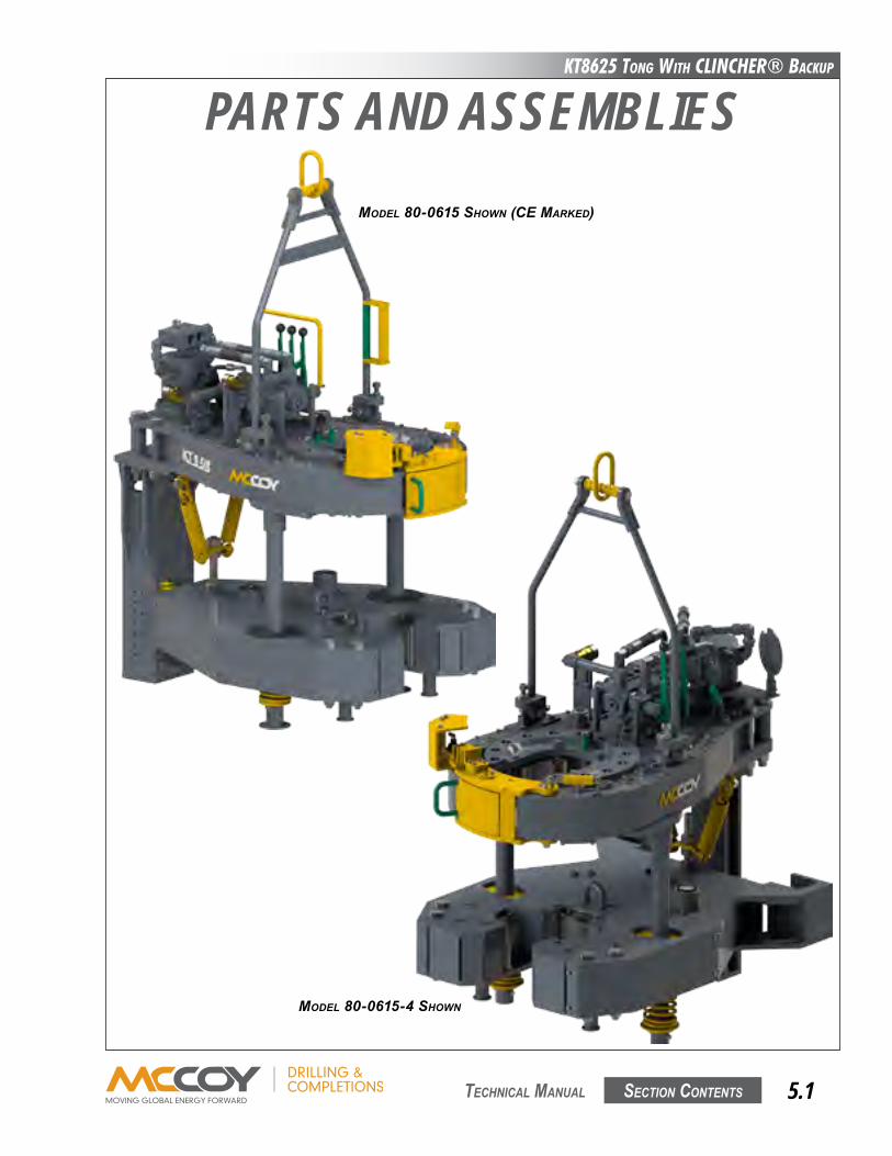
KT8625 Tong WiTh CLinChER® BaCKup
Section contentS 5.1 technical Manual
PARTS AND ASSEMBLIESMOdEL 80-0615 SHOwN (CE MARKEd)
MOdEL 80-0615-4 SHOwN
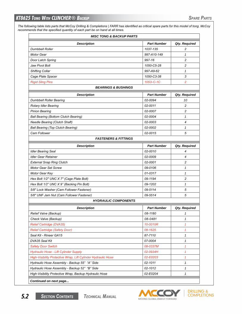
KT8625 Tong WiTh CLinChER® BaCKup
Section contentS5.2 technical Manual
SPaRe PaRtS
MISC TONG & BACKUP PARTS
Description Part Number Qty. RequiredDumbbellRoller 1037-135 2
MotorGear 997-A10-149 1
DoorLatchSpring 997-16 2
JawPivotBolt 1050-C5-28 2
ShiftingCollar 997-A9-62 1
CagePlateSpacer 1050-C3-38 3
RigidSlingPins 1053-C-1C 2
BEARINGS & BUSHINGS
Description Part Number Qty. RequiredDumbbellRollerBearing 02-0094 10
RotaryIdlerBearing 02-0011 2
PinionBearing 02-0007 2
BallBearing(BottomClutchBearing) 02-0004 1
NeedleBearing(ClutchShaft) 02-0003 4
BallBearing(TopClutchBearing) 02-0002 1
CamFollower 02-0015 5
FASTENERS & FITTINGS
Description Part Number Qty. RequiredIdlerBearingSeal 02-0010 4
IdlerGearRetainer 02-0009 4
ExternalSnapRingClutch 02-0001 2
MotorGearSetScrew 09-0106 1
MotorGearKey 01-0317 1
HexBolt1/2"UNCX7"(CagePlateBolt) 09-1194 2
HexBolt1/2”UNCX9”(BackingPinBolt) 09-1202 1
5/8"LockWasher(CamFollowerFastener) 09-5114 5
5/8"UNFJamNut(CamFollowerFastener) 09-5514 5
HYDRAULIC COMPONENTS
Description Part Number Qty. RequiredReliefValve(Backup) 08-1180 1
CheckValve(Backup) 08-0481 1
ReliefCartridge(DVA35) 10-0010R 1
ReliefCartridge(SafetyDoor) 08-1625 1
SealKit-RineerGA15 87-7110 1
DVA35SealKit 07-0004 1
SafetyDoorSwitch 08-0337M 1
HydraulicHose-LiftCylinderSupply 02-0934H 1
High-VisibilityProtectiveWrap,LiftCylinderHydraulicHose 02-E0203 1
HydraulicHoseAssembly-Backup55”“A”Side 02-1011 1
HydraulicHoseAssembly-Backup52”“B”Side 02-1012 1
High-VisibilityProtectiveWrap,BackupHydraulicHose 02-E0204 1
Continued on next page...
ThefollowingtablelistspartsthatMcCoyDrilling&Completions|FARRhasidentifiedascriticalsparepartsforthismodeloftong.McCoyrecommendsthatthespecifiedquantityofeachpartbeonhandatalltimes.
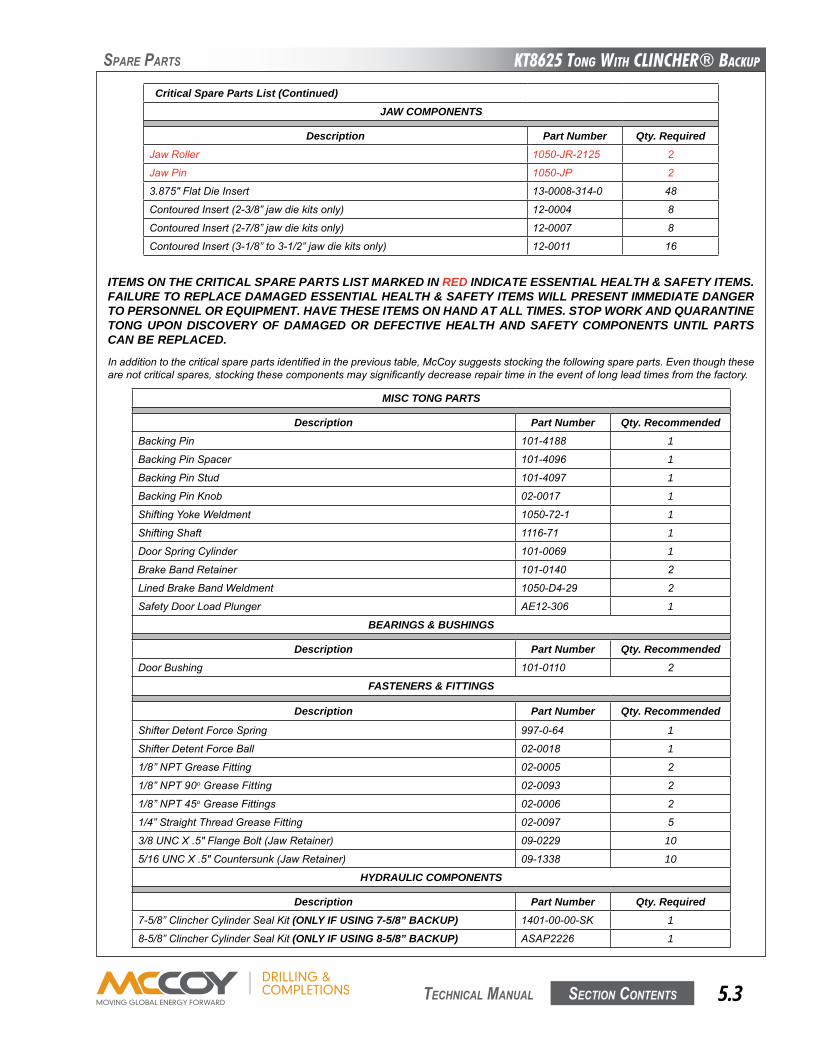
KT8625 Tong WiTh CLinChER® BaCKup
Section contentS 5.3 technical Manual
SPaRe PaRtS
Inadditiontothecriticalsparepartsidentifiedintheprevioustable,McCoysuggestsstockingthefollowingspareparts.Eventhoughthesearenotcriticalspares,stockingthesecomponentsmaysignificantlydecreaserepairtimeintheeventoflongleadtimesfromthefactory.
MISC TONG PARTS
Description Part Number Qty. RecommendedBackingPin 101-4188 1
BackingPinSpacer 101-4096 1
BackingPinStud 101-4097 1
BackingPinKnob 02-0017 1
ShiftingYokeWeldment 1050-72-1 1
ShiftingShaft 1116-71 1
DoorSpringCylinder 101-0069 1
BrakeBandRetainer 101-0140 2
LinedBrakeBandWeldment 1050-D4-29 2
SafetyDoorLoadPlunger AE12-306 1
BEARINGS & BUSHINGS
Description Part Number Qty. RecommendedDoorBushing 101-0110 2
FASTENERS & FITTINGS
Description Part Number Qty. Recommended
ShifterDetentForceSpring 997-0-64 1
ShifterDetentForceBall 02-0018 1
1/8”NPTGreaseFitting 02-0005 2
1/8”NPT90oGreaseFitting 02-0093 2
1/8”NPT45oGreaseFittings 02-0006 2
1/4”StraightThreadGreaseFitting 02-0097 5
3/8UNCX.5"FlangeBolt(JawRetainer) 09-0229 10
5/16UNCX.5"Countersunk(JawRetainer) 09-1338 10
HYDRAULIC COMPONENTS
Description Part Number Qty. Required7-5/8”ClincherCylinderSealKit(ONLY IF USING 7-5/8” BACKUP) 1401-00-00-SK 1
8-5/8”ClincherCylinderSealKit(ONLY IF USING 8-5/8” BACKUP) ASAP2226 1
Critical Spare Parts List (Continued)JAW COMPONENTS
Description Part Number Qty. RequiredJawRoller 1050-JR-2125 2
JawPin 1050-JP 2
3.875"FlatDieInsert 13-0008-314-0 48
ContouredInsert(2-3/8”jawdiekitsonly) 12-0004 8
ContouredInsert(2-7/8”jawdiekitsonly) 12-0007 8
ContouredInsert(3-1/8”to3-1/2”jawdiekitsonly) 12-0011 16
ITEMS ON THE CRITICAL SPARE PARTS LIST MARKED IN RED INDICATE ESSENTIAL HEALTH & SAFETY ITEMS. FAILURE TO REPLACE DAMAGED ESSENTIAL HEALTH & SAFETY ITEMS WILL PRESENT IMMEDIATE DANGER TO PERSONNEL OR EQUIPMENT. HAVE THESE ITEMS ON HAND AT ALL TIMES. STOP WORK AND QUARANTINE TONG UPON DISCOVERY OF DAMAGED OR DEFECTIVE HEALTH AND SAFETY COMPONENTS UNTIL PARTS CAN BE REPLACED.
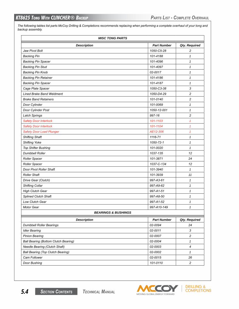
KT8625 Tong WiTh CLinChER® BaCKup
Section contentS5.4 technical Manual
PaRtS liSt - coMPlete oVeRhaul
MISC TONG PARTS
Description Part Number Qty. RequiredJawPivotBolt 1050-C5-28 2
BackingPin 101-4188 1
BackingPinSpacer 101-4096 1
BackingPinStud 101-4097 1
BackingPinKnob 02-0017 1
BackingPinRetainer 101-4186 1
BackingPinSpacer 101-4187 1
CagePlateSpacer 1050-C3-38 3
LinedBrakeBandWeldment 1050-D4-29 2
BrakeBandRetainers 101-0140 2
DoorCylinder 101-0069 1
DoorCylinderPost 1050-12-001 1
LatchSprings 997-16 2
SafetyDoorInterlock 101-1103 1
SafetyDoorInterlock 101-1104 1
SafetyDoorLoadPlunger AE12-306 1
ShiftingShaft 1116-71 1
ShiftingYoke 1050-72-1 1
TopShifterBushing 101-0020 1
DumbbellRoller 1037-135 12
RollerSpacer 101-3871 24
RollerSpacer 1037-C-134 12
DoorPivotRollerShaft 101-3940 1
RollerShaft 101-3939 11
DriveGear(Clutch) 997-A3-61 1
ShiftingCollar 997-A9-62 1
HighClutchGear 997-A1-51 1
SplinedClutchShaft 997-A8-50 1
LowClutchGear 997-A1-52 1
MotorGear 997-A10-149 1
BEARINGS & BUSHINGS
Description Part Number Qty. RequiredDumbbellRollerBearings 02-0094 24
IdlerBearing 02-0011 3
PinionBearing 02-0007 2
BallBearing(BottomClutchBearing) 02-0004 1
NeedleBearing(ClutchShaft) 02-0003 4
BallBearing(TopClutchBearing) 02-0002 1
CamFollower 02-0015 26
DoorBushing 101-0110 2
ThefollowingtableslistpartsMcCoyDrilling&Completionsrecommendsreplacingwhenperformingacompleteoverhaulofyourtongandbackupassembly.
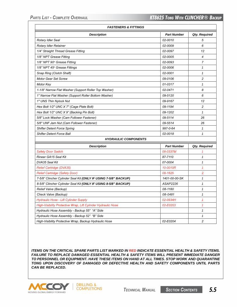
KT8625 Tong WiTh CLinChER® BaCKup
Section contentS 5.5 technical Manual
PaRtS liSt - coMPlete oVeRhaul
FASTENERS & FITTINGS
Description Part Number Qty. Required
RotaryIdlerSeal 02-0010 5
RotaryIdlerRetainer 02-0009 6
1/4”StraightThreadGreaseFitting 02-0097 12
1/8”NPTGreaseFitting 02-0005 4
1/8”NPT90oGreaseFitting 02-0093 7
1/8”NPT45oGreaseFittings 02-0006 1
SnapRing(ClutchShaft) 02-0001 1
MotorGearSetScrew 09-0106 2
MotorKey 01-0317 1
1-1/8”NarrowFlatWasher(SupportRollerTopWasher) 02-0471 8
1”NarrowFlatWasher(SupportRollerBottomWasher) 09-5120 6
1"UNSThinNylockNut 09-9167 12
HexBolt1/2"UNCX7"(CagePlateBolt) 09-1194 2
HexBolt1/2”UNCX9”(BackingPinBolt) 09-1202 1
5/8"LockWasher(CamFollowerFastener) 09-5114 26
5/8"UNFJamNut(CamFollowerFastener) 09-5514 26
ShifterDetentForceSpring 997-0-64 1
ShifterDetentForceBall 02-0018 1
HYDRAULIC COMPONENTS
Description Part Number Qty. RequiredSafetyDoorSwitch 08-0337M 1
RineerGA15SealKit 87-7110 1
DVA35SealKit 07-0004 1
ReliefCartridge(DVA35) 10-0010R 1
ReliefCartridge(SafetyDoor) 08-1625 2
7-5/8”ClincherCylinderSealKit(ONLY IF USING 7-5/8” BACKUP) 1401-00-00-SK 1
8-5/8”ClincherCylinderSealKit(ONLY IF USING 8-5/8” BACKUP) ASAP2226 1
ReliefValve(Backup) 08-1180 1
CheckValve(Backup) 08-0481 1
HydraulicHose-LiftCylinderSupply 02-0934H 1
High-VisibilityProtectiveWrap,LiftCylinderHydraulicHose 02-E0203 1
HydraulicHoseAssembly-Backup55”“A”Side 1
HydraulicHoseAssembly-Backup52”“B”Side 1
High-VisibilityProtectiveWrap,BackupHydraulicHose 02-E0204 2
ITEMS ON THE CRITICAL SPARE PARTS LIST MARKED IN RED INDICATE ESSENTIAL HEALTH & SAFETY ITEMS. FAILURE TO REPLACE DAMAGED ESSENTIAL HEALTH & SAFETY ITEMS WILL PRESENT IMMEDIATE DANGER TO PERSONNEL OR EQUIPMENT. HAVE THESE ITEMS ON HAND AT ALL TIMES. STOP WORK AND QUARANTINE TONG UPON DISCOVERY OF DAMAGED OR DEFECTIVE HEALTH AND SAFETY COMPONENTS UNTIL PARTS CAN BE REPLACED.
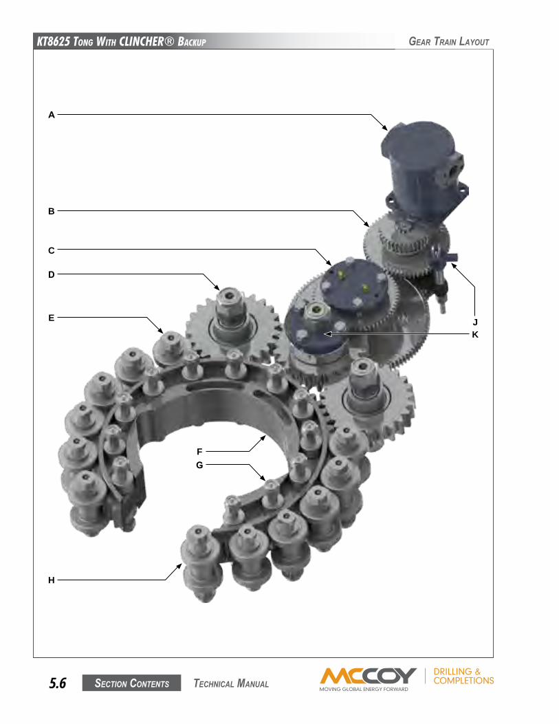
KT8625 Tong WiTh CLinChER® BaCKup
Section contentS5.6 technical Manual
GeaR tRain layout
B
C
D
H
J
A
K
E
FG
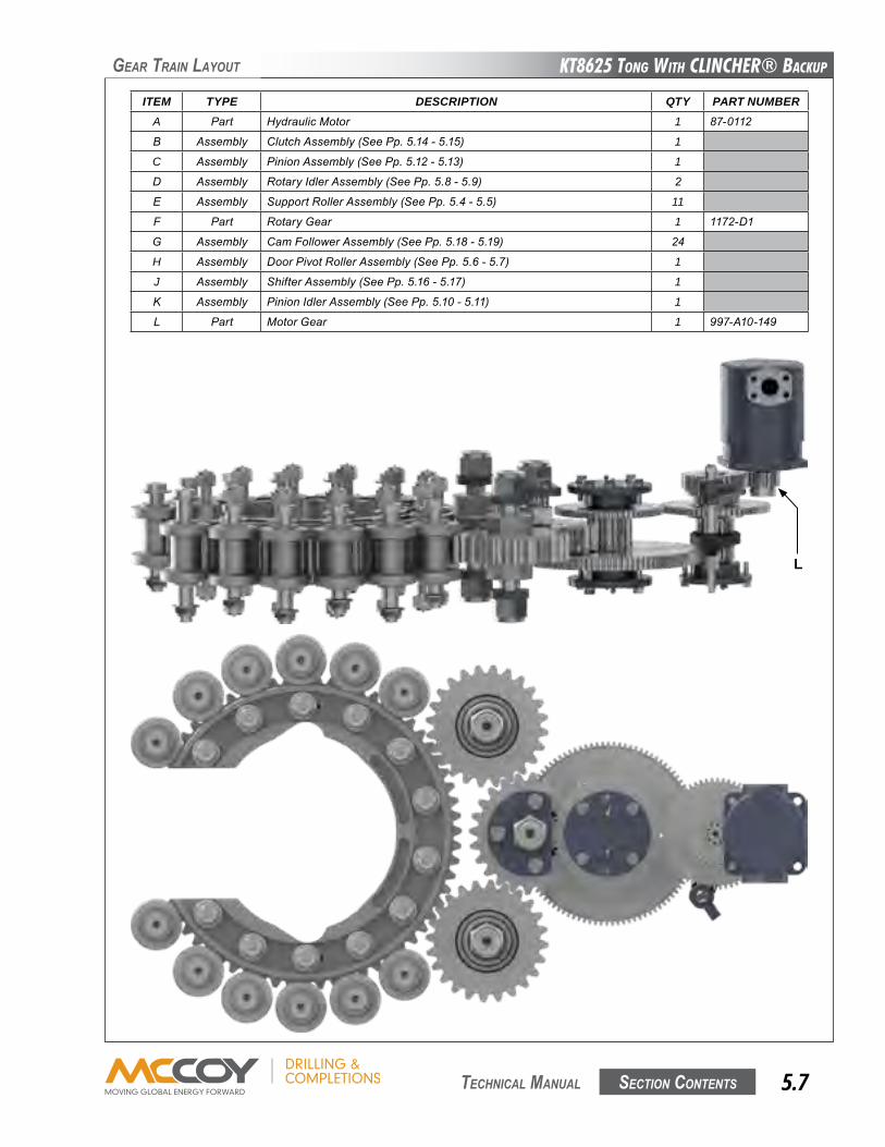
KT8625 Tong WiTh CLinChER® BaCKup
Section contentS 5.7 technical Manual
GeaR tRain layout
ITEM TYPE DESCRIPTION QTY PART NUMBERA Part HydraulicMotor 1 87-0112
B Assembly ClutchAssembly(SeePp.5.14-5.15) 1
C Assembly PinionAssembly(SeePp.5.12-5.13) 1
D Assembly RotaryIdlerAssembly(SeePp.5.8-5.9) 2
E Assembly SupportRollerAssembly(SeePp.5.4-5.5) 11
F Part RotaryGear 1 1172-D1
G Assembly CamFollowerAssembly(SeePp.5.18-5.19) 24
H Assembly DoorPivotRollerAssembly(SeePp.5.6-5.7) 1
J Assembly ShifterAssembly(SeePp.5.16-5.17) 1
K Assembly PinionIdlerAssembly(SeePp.5.10-5.11) 1
L Part MotorGear 1 997-A10-149
L
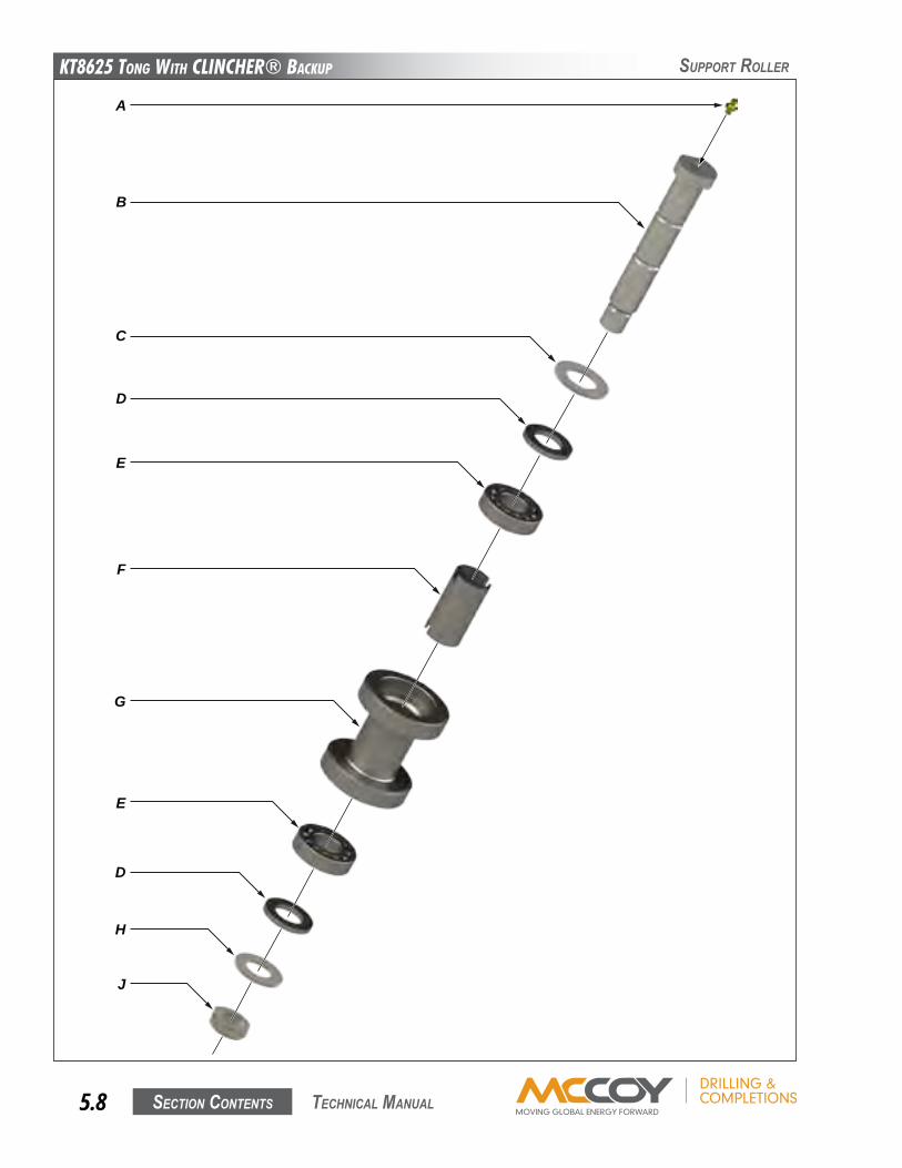
KT8625 Tong WiTh CLinChER® BaCKup
Section contentS5.8 technical Manual
SuPPoRt RolleR
A
B
C
D
E
F
G
E
D
H
J
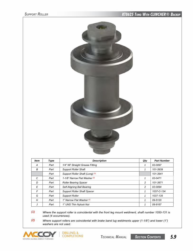
KT8625 Tong WiTh CLinChER® BaCKup
Section contentS 5.9 technical Manual
SuPPoRt RolleR
Item Type Description Qty Part NumberA Part 1/4”NFStraightGreaseFitting 1 02-0097
B Part SupportRollerShaft 1 101-3939
Part SupportRollerShaft(Long)(1) 101-3941
C Part 1-1/8”NarrowFlatWasher(2) 1 02-0471
D Part RollerBearingSpacer 2 101-3871
E Part Self-AligningBallBearing 2 02-0094
F Part SupportRollerShaftSpacer 1 1037-C-134
G Part SupportRoller 1 1037-135
H Part 1”NarrowFlatWasher(2) 1 09-5120
J Part 1”UNSThinNylockNut 1 09-9167
(1) Wherethesupportrolleriscoincidentalwiththefrontlegmountweldment,shaftnumber1050-131is used(4occurrences).(2) Wheresupportrollersarecoincidentalwithbrakebandlugweldmentsupper(1-1/8”)andlower(1”) washersarenotused.
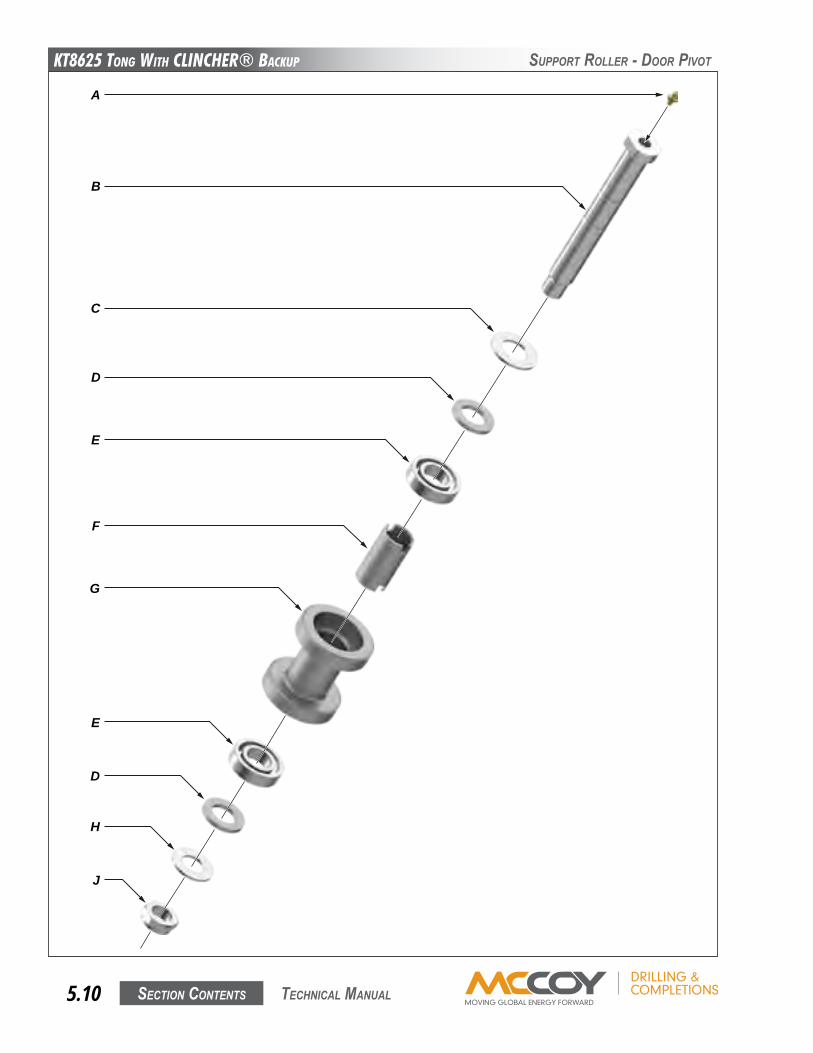
KT8625 Tong WiTh CLinChER® BaCKup
Section contentS5.10 technical Manual
SuPPoRt RolleR - DooR PiVot
A
B
C
D
E
F
G
E
D
H
J
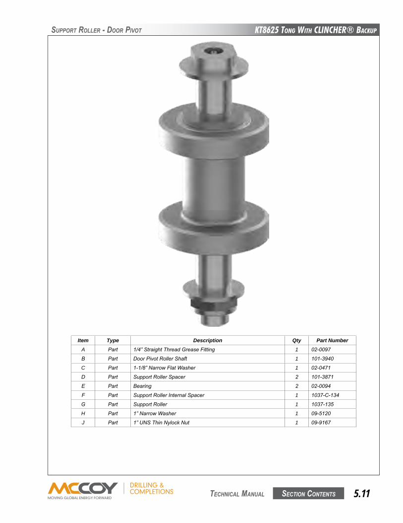
KT8625 Tong WiTh CLinChER® BaCKup
Section contentS 5.11 technical Manual
SuPPoRt RolleR - DooR PiVot
Item Type Description Qty Part NumberA Part 1/4”StraightThreadGreaseFitting 1 02-0097
B Part DoorPivotRollerShaft 1 101-3940
C Part 1-1/8”NarrowFlatWasher 1 02-0471
D Part SupportRollerSpacer 2 101-3871
E Part Bearing 2 02-0094
F Part SupportRollerInternalSpacer 1 1037-C-134
G Part SupportRoller 1 1037-135
H Part 1”NarrowWasher 1 09-5120
J Part 1”UNSThinNylockNut 1 09-9167
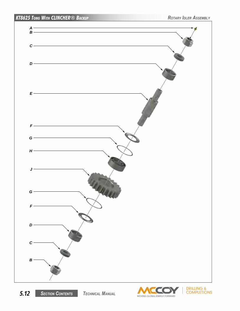
KT8625 Tong WiTh CLinChER® BaCKup
Section contentS5.12 technical Manual
RotaRy iDleR aSSeMBly
AB
C
E
F
G
H
J
G
F
D
C
B
D
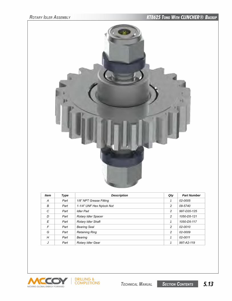
KT8625 Tong WiTh CLinChER® BaCKup
Section contentS 5.13 technical Manual
RotaRy iDleR aSSeMBly
Item Type Description Qty Part NumberA Part 1/8”NPTGreaseFitting 1 02-0005
B Part 1-1/4”UNFHexNylockNut 2 09-5740
C Part IdlerPad 2 997-D20-125
D Part RotaryIdlerSpacer 2 1050-D5-121
E Part RotaryIdlerShaft 1 1050-D5-117
F Part BearingSeal 2 02-0010
G Part RetainingRing 2 02-0009
H Part Bearing 1 02-0011
J Part RotaryIdlerGear 1 997-A2-119
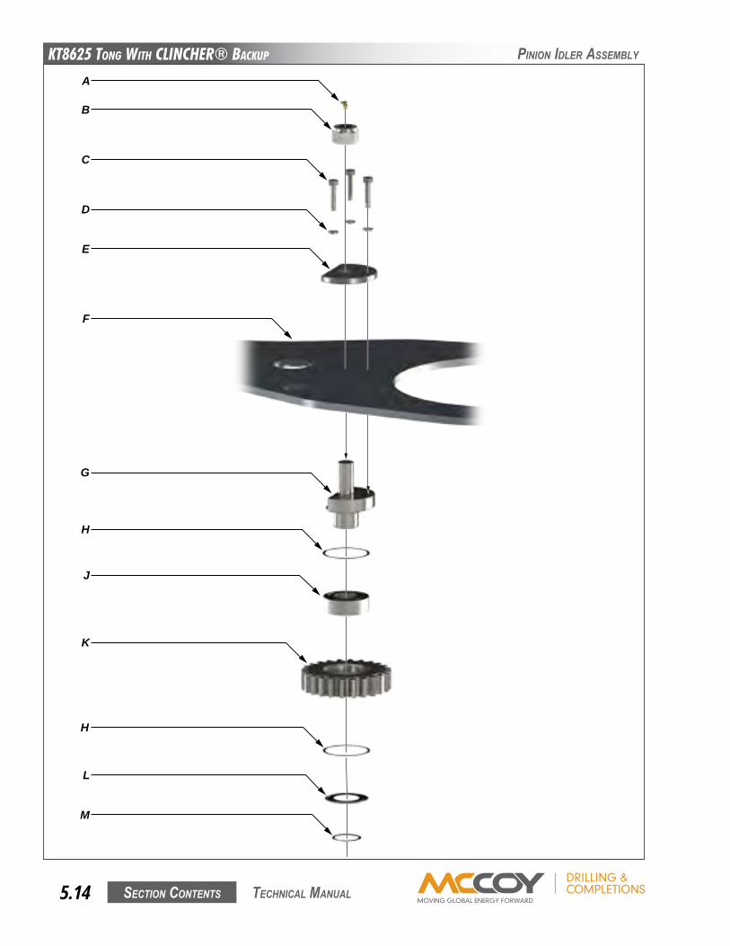
KT8625 Tong WiTh CLinChER® BaCKup
Section contentS5.14 technical Manual
Pinion iDleR aSSeMBly
A
B
C
E
L
M
D
F
H
K
J
G
H
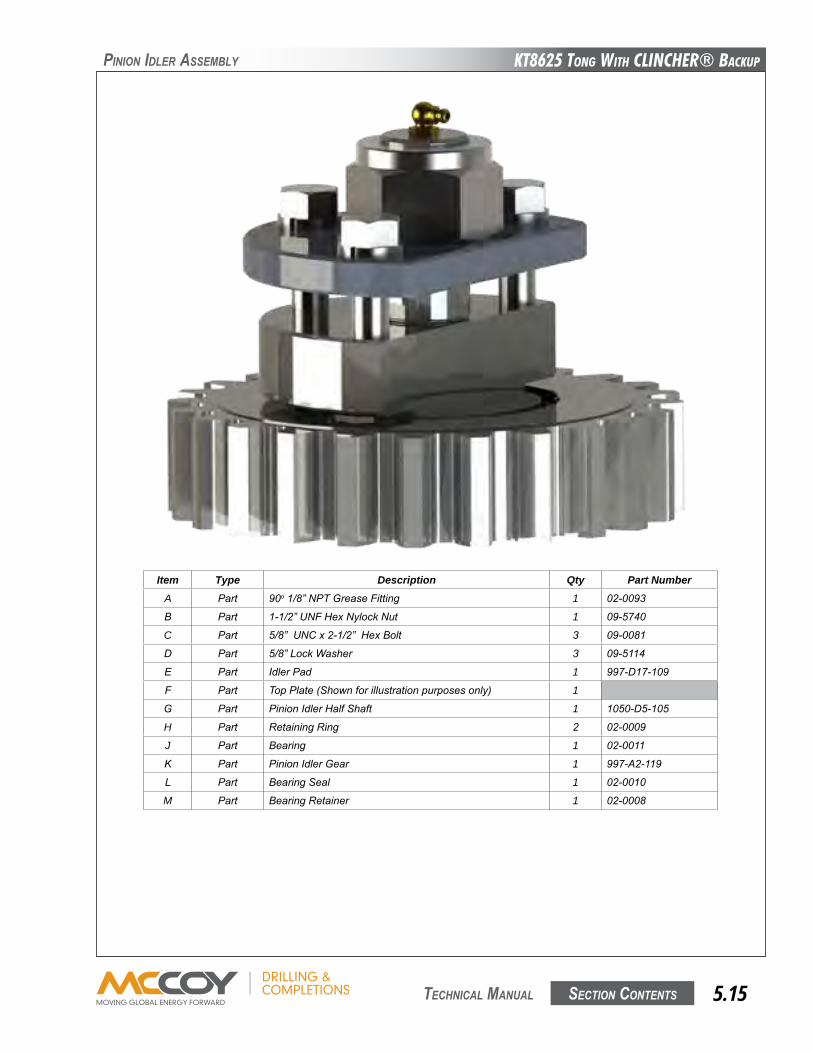
KT8625 Tong WiTh CLinChER® BaCKup
Section contentS 5.15 technical Manual
Pinion iDleR aSSeMBly
Item Type Description Qty Part NumberA Part 90o1/8”NPTGreaseFitting 1 02-0093
B Part 1-1/2”UNFHexNylockNut 1 09-5740
C Part 5/8”UNCx2-1/2”HexBolt 3 09-0081
D Part 5/8”LockWasher 3 09-5114
E Part IdlerPad 1 997-D17-109
F Part TopPlate(Shownforillustrationpurposesonly) 1
G Part PinionIdlerHalfShaft 1 1050-D5-105
H Part RetainingRing 2 02-0009
J Part Bearing 1 02-0011
K Part PinionIdlerGear 1 997-A2-119
L Part BearingSeal 1 02-0010
M Part BearingRetainer 1 02-0008
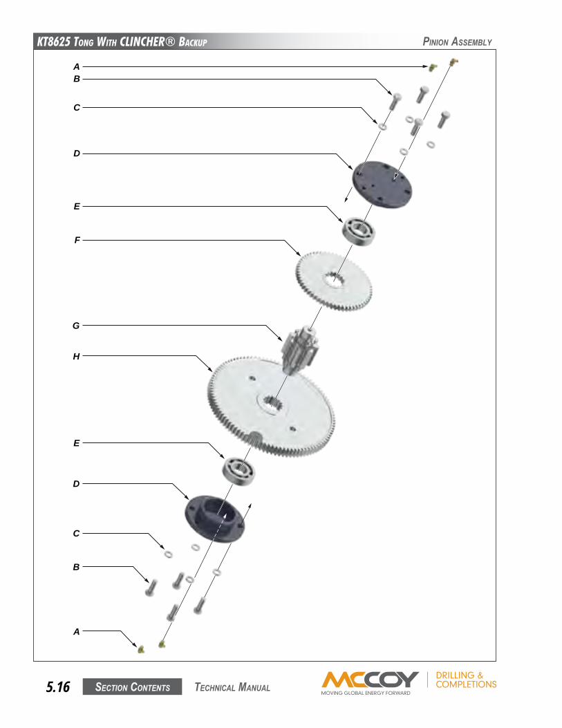
KT8625 Tong WiTh CLinChER® BaCKup
Section contentS5.16 technical Manual
Pinion aSSeMBly
AB
C
E
F
G
H
E
D
C
B
A
D
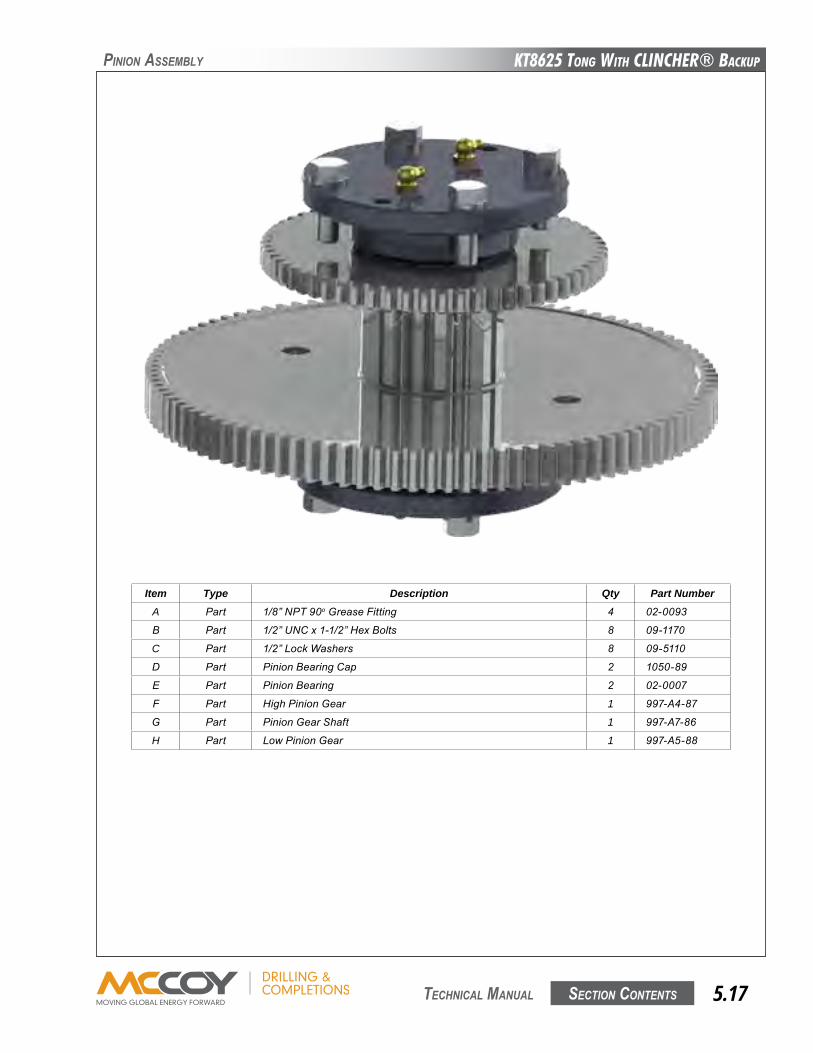
KT8625 Tong WiTh CLinChER® BaCKup
Section contentS 5.17 technical Manual
Item Type Description Qty Part NumberA Part 1/8”NPT90oGreaseFitting 4 02-0093
B Part 1/2”UNCx1-1/2”HexBolts 8 09-1170
C Part 1/2”LockWashers 8 09-5110
D Part PinionBearingCap 2 1050-89
E Part PinionBearing 2 02-0007
F Part HighPinionGear 1 997-A4-87
G Part PinionGearShaft 1 997-A7-86
H Part LowPinionGear 1 997-A5-88
Pinion aSSeMBly

KT8625 Tong WiTh CLinChER® BaCKup
Section contentS5.18 technical Manual
clutch aSSeMBly
AB
C
D
K
J
H
S
P
M
N
R
E
F
G
H
L
Q
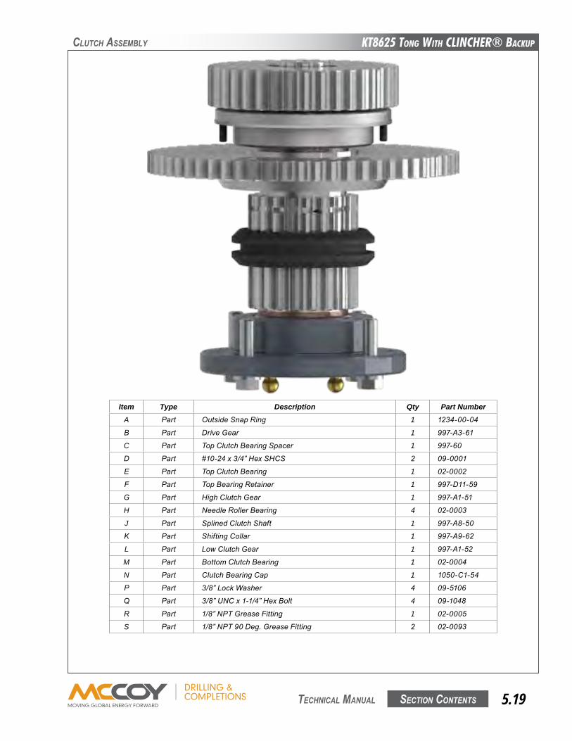
KT8625 Tong WiTh CLinChER® BaCKup
Section contentS 5.19 technical Manual
clutch aSSeMBly
Item Type Description Qty Part NumberA Part OutsideSnapRing 1 1234-00-04
B Part DriveGear 1 997-A3-61
C Part TopClutchBearingSpacer 1 997-60
D Part #10-24x3/4”HexSHCS 2 09-0001
E Part TopClutchBearing 1 02-0002
F Part TopBearingRetainer 1 997-D11-59
G Part HighClutchGear 1 997-A1-51
H Part NeedleRollerBearing 4 02-0003
J Part SplinedClutchShaft 1 997-A8-50
K Part ShiftingCollar 1 997-A9-62
L Part LowClutchGear 1 997-A1-52
M Part BottomClutchBearing 1 02-0004
N Part ClutchBearingCap 1 1050-C1-54
P Part 3/8”LockWasher 4 09-5106
q Part 3/8”UNCx1-1/4”HexBolt 4 09-1048
R Part 1/8”NPTGreaseFitting 1 02-0005
S Part 1/8”NPT90Deg.GreaseFitting 2 02-0093
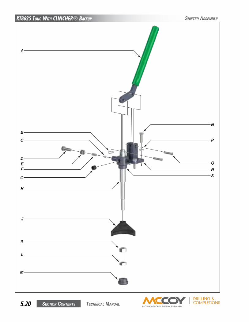
KT8625 Tong WiTh CLinChER® BaCKup
Section contentS5.20 technical Manual
ShifteR aSSeMBly
A
B
J
L
M
K
F
C
E
H
D
G
Q
P
N
RS
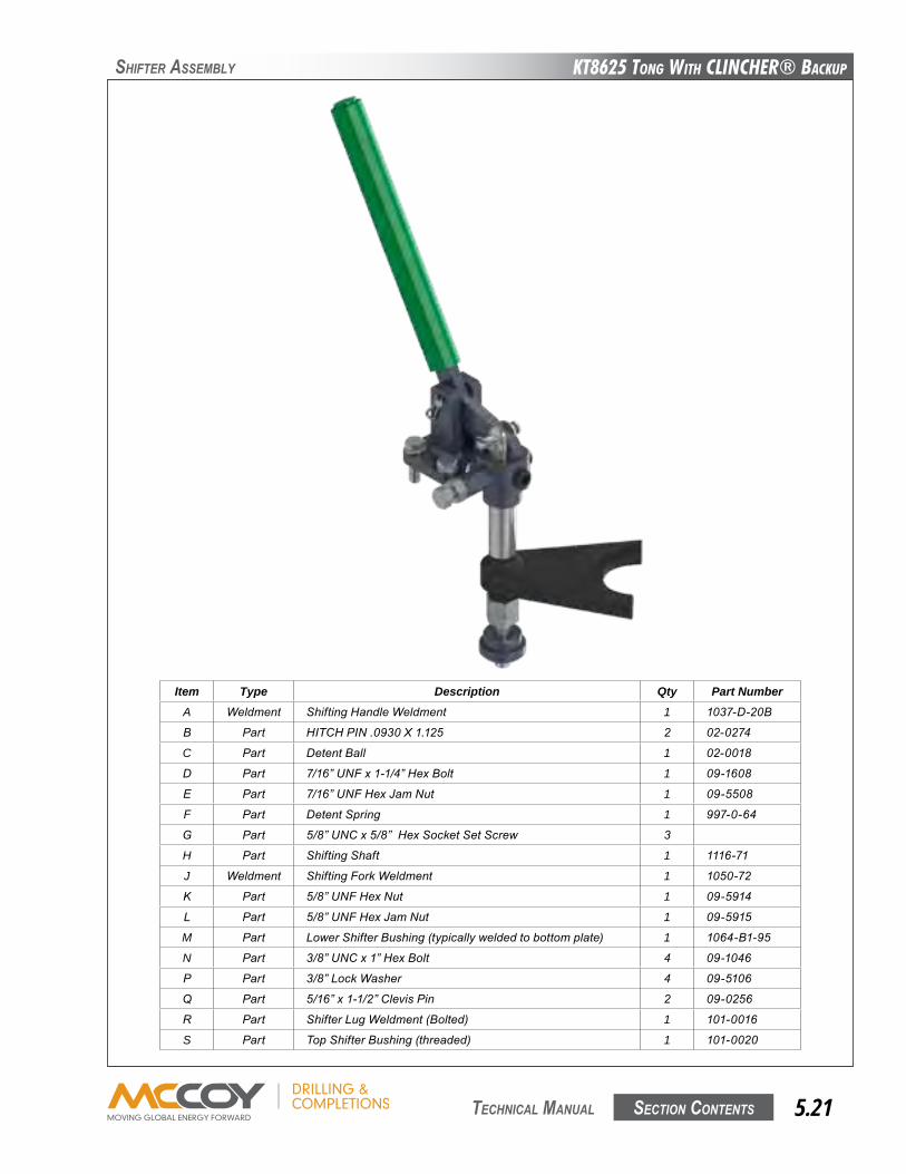
KT8625 Tong WiTh CLinChER® BaCKup
Section contentS 5.21 technical Manual
Item Type Description Qty Part NumberA Weldment ShiftingHandleWeldment 1 1037-D-20B
B Part HITCHPIN.0930X1.125 2 02-0274
C Part DetentBall 1 02-0018
D Part 7/16”UNFx1-1/4”HexBolt 1 09-1608
E Part 7/16”UNFHexJamNut 1 09-5508
F Part DetentSpring 1 997-0-64
G Part 5/8”UNCx5/8”HexSocketSetScrew 3
H Part ShiftingShaft 1 1116-71
J Weldment ShiftingForkWeldment 1 1050-72
K Part 5/8”UNFHexNut 1 09-5914
L Part 5/8”UNFHexJamNut 1 09-5915
M Part LowerShifterBushing(typicallyweldedtobottomplate) 1 1064-B1-95
N Part 3/8”UNCx1”HexBolt 4 09-1046
P Part 3/8”LockWasher 4 09-5106
q Part 5/16”x1-1/2”ClevisPin 2 09-0256
R Part ShifterLugWeldment(Bolted) 1 101-0016
S Part TopShifterBushing(threaded) 1 101-0020
ShifteR aSSeMBly

KT8625 Tong WiTh CLinChER® BaCKup
Section contentS5.22 technical Manual
RotaRy aSSeMBly
A
B
C
D
K
J
L
T
U
Q
N
P
S
E
F
G
H
M
R
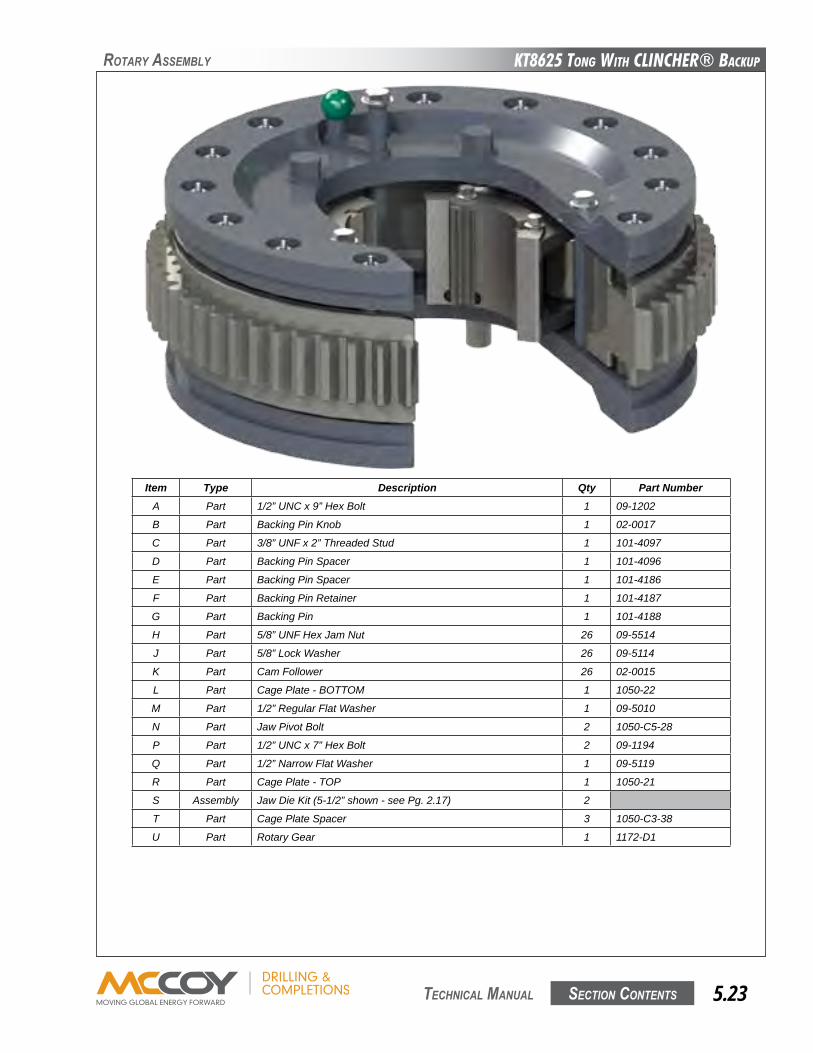
KT8625 Tong WiTh CLinChER® BaCKup
Section contentS 5.23 technical Manual
RotaRy aSSeMBly
Item Type Description Qty Part NumberA Part 1/2” UNC x 9” Hex Bolt 1 09-1202
B Part Backing Pin Knob 1 02-0017
C Part 3/8” UNF x 2” Threaded Stud 1 101-4097
D Part Backing Pin Spacer 1 101-4096
E Part Backing Pin Spacer 1 101-4186
F Part Backing Pin Retainer 1 101-4187
G Part Backing Pin 1 101-4188
H Part 5/8” UNF Hex Jam Nut 26 09-5514
J Part 5/8” Lock Washer 26 09-5114
K Part Cam Follower 26 02-0015
L Part Cage Plate - BOTTOM 1 1050-22
M Part 1/2” Regular Flat Washer 1 09-5010
N Part Jaw Pivot Bolt 2 1050-C5-28
P Part 1/2” UNC x 7” Hex Bolt 2 09-1194
Q Part 1/2” Narrow Flat Washer 1 09-5119
R Part Cage Plate - TOP 1 1050-21
S Assembly Jaw Die Kit (5-1/2” shown - see Pg. 2.17) 2
T Part Cage Plate Spacer 3 1050-C3-38
U Part Rotary Gear 1 1172-D1
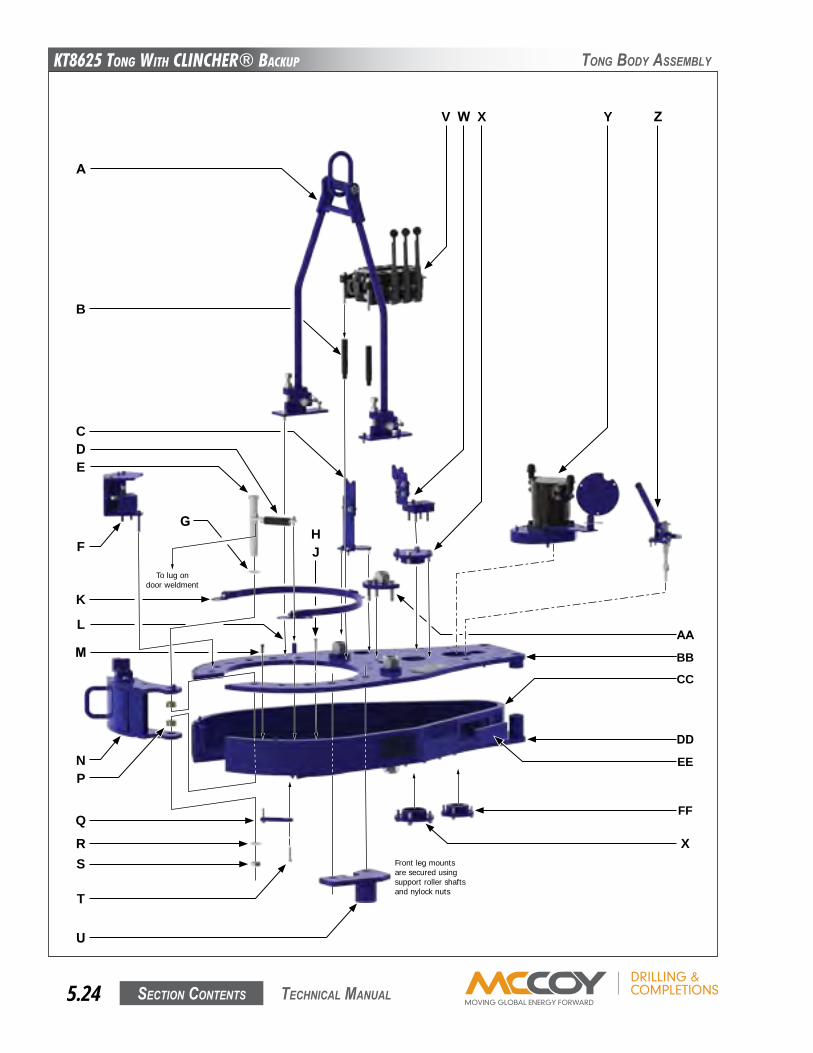
KT8625 Tong WiTh CLinChER® BaCKup
Section contentS5.24 technical Manual
tonG BoDy aSSeMBly
To lug ondoor weldment
Front leg mountsare secured usingsupport roller shaftsand nylock nuts
A
B
CD
N
Q
P
W XV
AA
X
FF
E
G
F
K
RS
T
U
Y Z
BB
CC
EE
L
M
HJ
DD
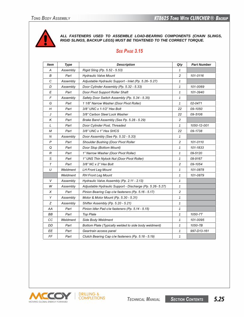
KT8625 Tong WiTh CLinChER® BaCKup
Section contentS 5.25 technical Manual
tonG BoDy aSSeMBly
Item Type Description Qty Part NumberA Assembly RigidSling(Pp.5.52-5.53) 1
B Part HydraulicValveMount 2 101-0116
C Assembly AdjustableHydraulicSupport-Inlet(Pp.5.26-5.27) 1
D Assembly DoorCylinderAssembly(Pp.5.32-5.33) 1 101-0069
E Part DoorPivotSupportRollerShaft 1 101-3940
F Assembly SafetyDoorSwitchAssembly(Pp.5.34-5.35) 1
G Part 11/8”NarrowWasher(DoorPivotRoller) 1 02-0471
H Part 3/8”UNCx1-1/2”HexBolt 22 09-1050
J Part 3/8”CarbonSteelLockWasher 22 09-5106
K Part BrakeBandAssembly(SeePp.5.28-5.29) 2
L Part DoorCylinderPost,Threaded 1 1050-12-001
M Part 3/8”UNCx1”HexSHCS 22 09-1738
N Assembly DoorAssembly(SeePp.5.32-5.33) 1
P Part ShoulderBushing(DoorPivotRoller 2 101-0110
q Part DoorStop(BottomMount) 1 101-1833
R Part 1”NarrowWasher(DoorPivotRoller) 1 09-5120
S Part 1”UNSThinNylockNut(DoorPivotRoller) 1 09-9167
T Part 3/8”NCx2”HexBolt 2 09-1054
U Weldment LHFrontLegMount 1 101-0878
Weldment RHFrontLegMount 1 101-0879
V Assembly HydraulicValveAssembly(Pp.2.11-2.13) 1
W Assembly AdjustableHydraulicSupport-Discharge(Pp.5.26-5.27) 1
X Part PinionBearingCapc/wfasteners(Pp.5.16-5.17) 2
Y Assembly Motor&MotorMount(Pp.5.30-5.31) 1
z Assembly ShifterAssembly(Pp.5.20-5.21) 1
AA Part PinionIdlerPadc/wfasteners(Pp.5.14-5.15) 1
BB Part TopPlate 1 1050-7T
CC Weldment SideBodyWeldment 1 101-0095
DD Part BottomPlate(Typicallyweldedtosidebodyweldment) 1 1050-7B
EE Part Geartrainaccesspanel 1 997-D13-161
FF Part ClutchBearingCapc/wfasteners(Pp.5.18-5.19) 1
See PaGe 3.15
ALL FASTENERS USED TO ASSEMBLE LOAD-BEARING COMPONENTS (CHAIN SLINGS, RIGID SLINGS, BACKUP LEGS) MUST BE TIGHTENED TO THE CORRECT TORQUE.
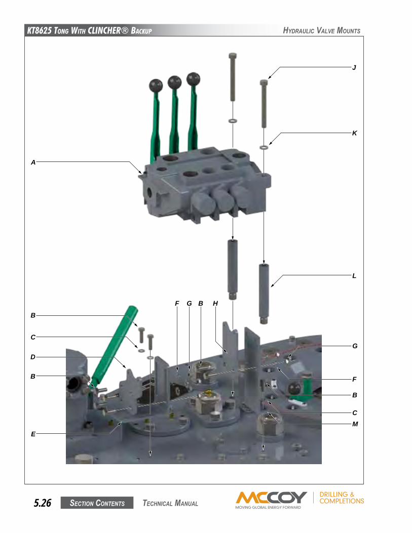
KT8625 Tong WiTh CLinChER® BaCKup
Section contentS5.26 technical Manual
hyDRaulic ValVe MountS
A
C
D
E
B
G
L
K
J
F
B
CM
B
F G B H
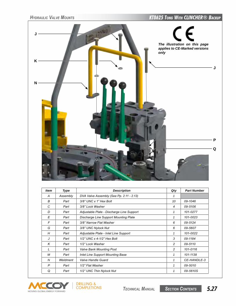
KT8625 Tong WiTh CLinChER® BaCKup
Section contentS 5.27 technical Manual
hyDRaulic ValVe MountS
Item Type Description Qty Part NumberA Assembly DVAValveAssembly(SeePp.2.11-2.13) 1
B Part 3/8”UNCx1”HexBolt 10 09-1046
C Part 3/8”LockWasher 4 09-5106
D Part AdjustablePlate-DischargeLineSupport 1 101-0277
E Part DischargeLineSupportMountingPlate 1 101-0023
F Part 3/8”NarrowFlatWasher 6 09-5124
G Part 3/8”UNCNylockNut 6 09-5607
H Part AdjustablePlate-InletLineSupport 1 101-0022
J Part 1/2”UNCx4-1/2”HexBolt 3 09-1184
K Part 1/2”LockWasher 2 09-5110
L Part ValveBankMountingPost 2 101-0116
M Part InletLineSupportMountingBase 1 101-1138
N Weldment ValveHandleGuard 1 CE-HANDLE-3
P Part 1/2”FlatWasher 1 09-5010
q Part 1/2”UNCThinNylockNut 1 09-5610S
P
J
K
N
Q
The illustration on this page applies to CE-Marked versions only
J
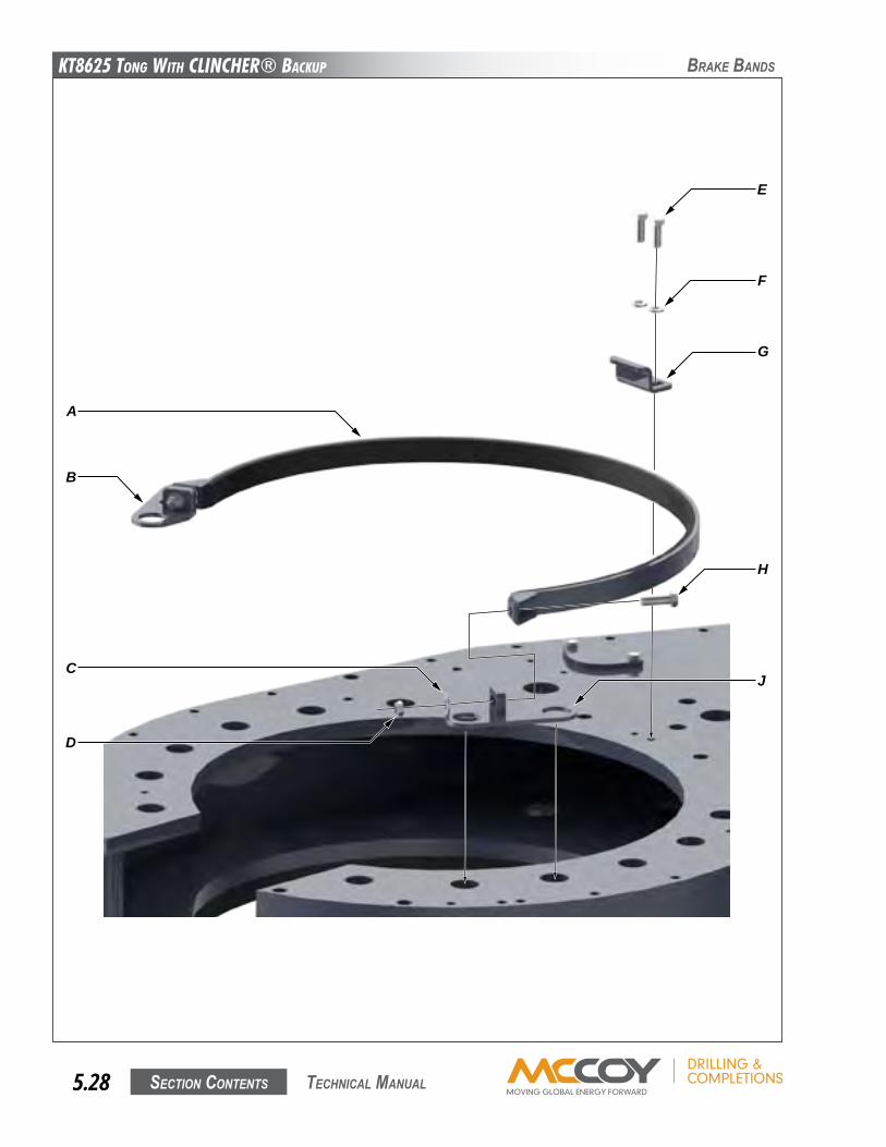
KT8625 Tong WiTh CLinChER® BaCKup
Section contentS5.28 technical Manual
BRaKe BanDS
A
C
G
H
J
D
F
E
B
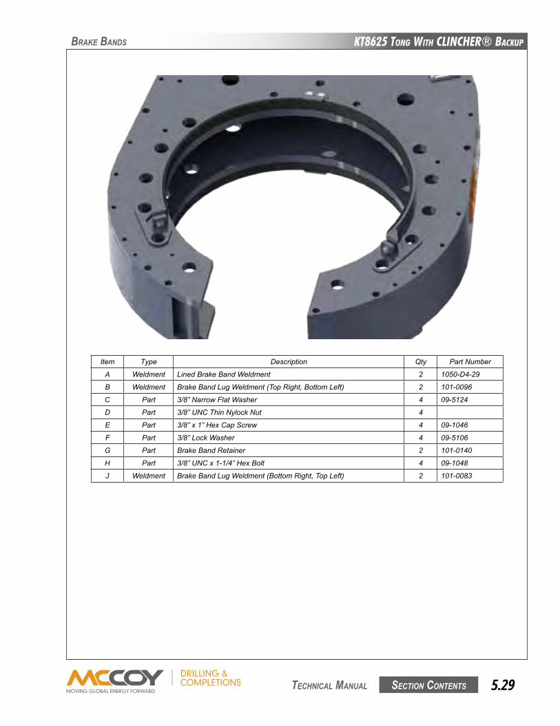
KT8625 Tong WiTh CLinChER® BaCKup
Section contentS 5.29 technical Manual
BRaKe BanDS
Item Type Description qty PartNumber
A Weldment LinedBrakeBandWeldment 2 1050-D4-29
B Weldment BrakeBandLugWeldment(TopRight,BottomLeft) 2 101-0096
C Part 3/8”NarrowFlatWasher 4 09-5124
D Part 3/8”UNCThinNylockNut 4
E Part 3/8”x1”HexCapScrew 4 09-1046
F Part 3/8”LockWasher 4 09-5106
G Part BrakeBandRetainer 2 101-0140
H Part 3/8”UNCx1-1/4”HexBolt 4 09-1048
J Weldment BrakeBandLugWeldment(BottomRight,TopLeft) 2 101-0083
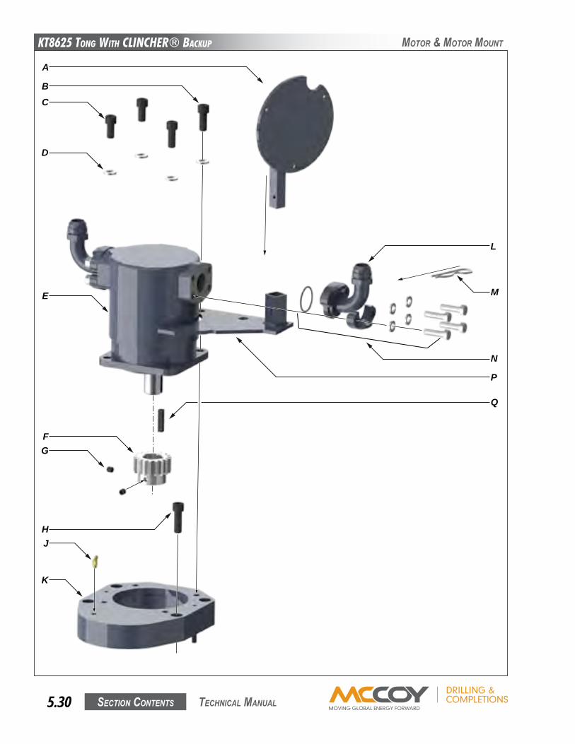
KT8625 Tong WiTh CLinChER® BaCKup
Section contentS5.30 technical Manual
MotoR & MotoR Mount
A
C
K
G
D
F
J
E
H
N
M
L
P
Q
B
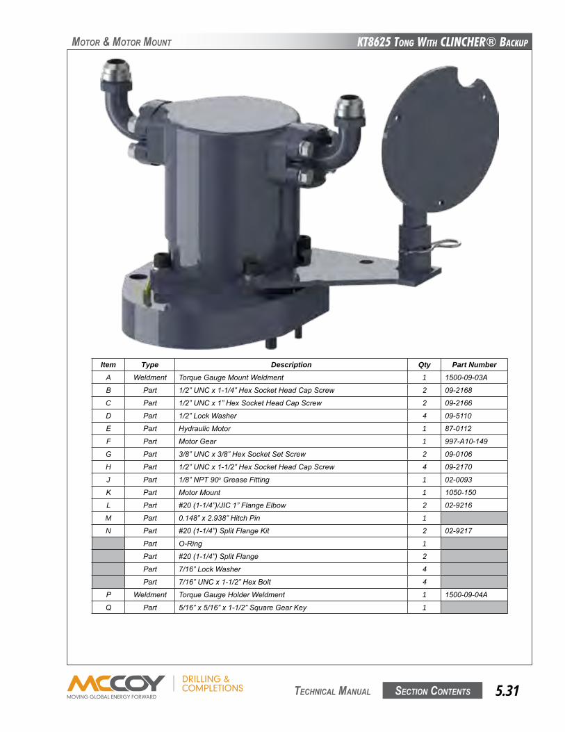
KT8625 Tong WiTh CLinChER® BaCKup
Section contentS 5.31 technical Manual
MotoR & MotoR Mount
Item Type Description Qty Part NumberA Weldment TorqueGaugeMountWeldment 1 1500-09-03A
B Part 1/2”UNCx1-1/4”HexSocketHeadCapScrew 2 09-2168
C Part 1/2”UNCx1”HexSocketHeadCapScrew 2 09-2166
D Part 1/2”LockWasher 4 09-5110
E Part HydraulicMotor 1 87-0112
F Part MotorGear 1 997-A10-149
G Part 3/8”UNCx3/8”HexSocketSetScrew 2 09-0106
H Part 1/2”UNCx1-1/2”HexSocketHeadCapScrew 4 09-2170
J Part 1/8”NPT90oGreaseFitting 1 02-0093
K Part MotorMount 1 1050-150
L Part #20(1-1/4”)/JIC1”FlangeElbow 2 02-9216
M Part 0.148”x2.938”HitchPin 1
N Part #20(1-1/4”)SplitFlangeKit 2 02-9217
Part O-Ring 1
Part #20(1-1/4”)SplitFlange 2
Part 7/16”LockWasher 4
Part 7/16”UNCx1-1/2”HexBolt 4
P Weldment TorqueGaugeHolderWeldment 1 1500-09-04A
q Part 5/16”x5/16”x1-1/2”SquareGearKey 1
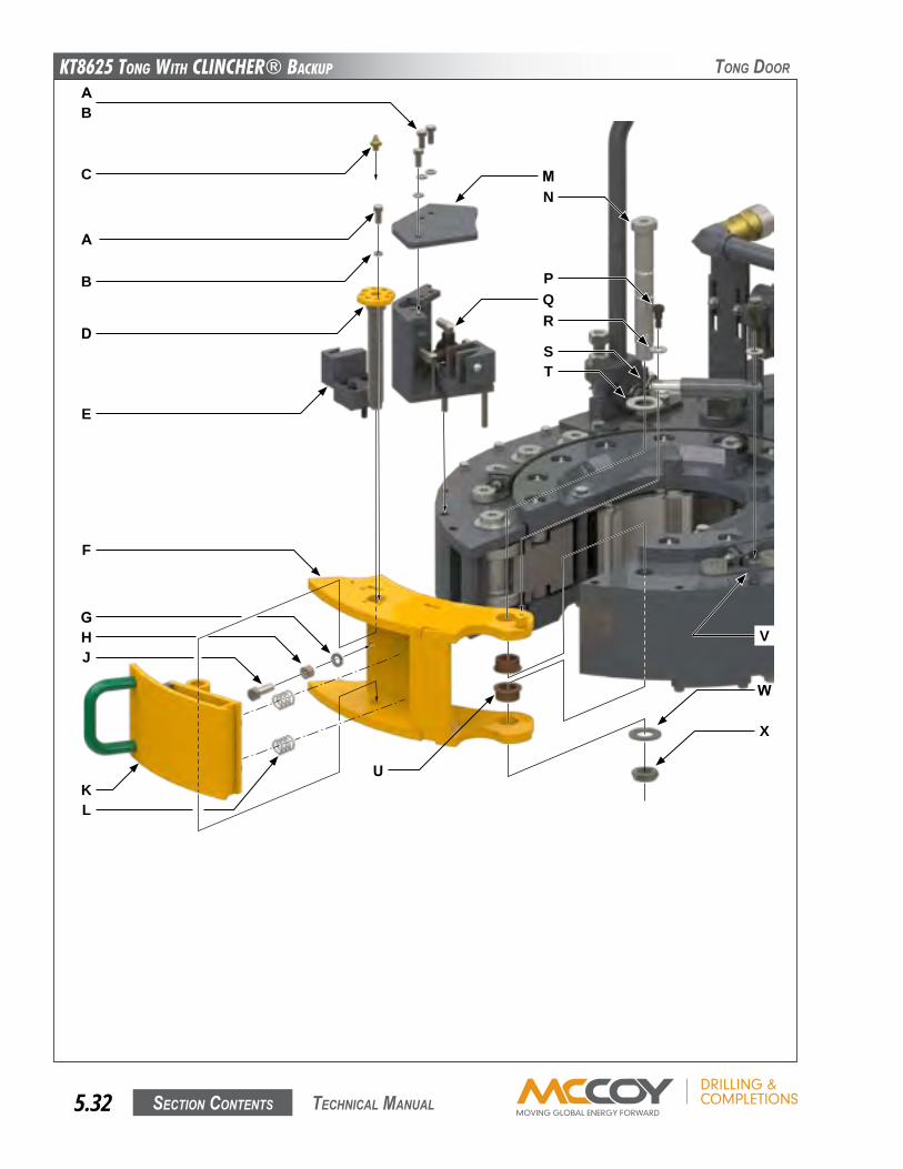
KT8625 Tong WiTh CLinChER® BaCKup
Section contentS5.32 technical Manual
tonG DooR
A
C
A
B
D
E
F
M
GHJ
KU
QR
T
V
P
B
N
W
X
S
L
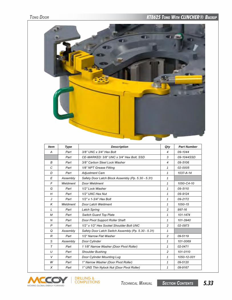
KT8625 Tong WiTh CLinChER® BaCKup
Section contentS 5.33 technical Manual
Item Type Description Qty Part NumberA Part 3/8”UNCx3/4”HexBolt 4 09-1044
Part CE-MARKED:3/8”UNCx3/4”HexBolt,SSD 3 09-1044SSD
B Part 3/8”CarbonSteelLockWasher 4 09-5106
C Part 1/8”NPTGreaseFitting 1 02-0005
D Part AdjustmentCam 1 1037-A-14
E Assembly SafetyDoorLatchBlockAssembly(Pp.5.30-5.31) 1
F Weldment DoorWeldment 1 1050-C4-10
G Part 1/2”LockWasher 1 09-5110
H Part 1/2”UNCHexNut 1 09-9124
J Part 1/2”x1-3/4”HexBolt 1 09-2172
K Weldment DoorLatchWeldment 1 1050-15
L Part LatchSpring 2 997-16
M Part SwitchGuardTopPlate 1 101-1474
N Part DoorPivotSupportRollerShaft 1 101-3940
P Part 1/2”x1/2”HexSocketShoulderBoltUNC 2 02-0973
q Assembly SafetyDoorLatchSwitchAssembly(Pp.5.30-5.31) 1
R Part 1/2”NarrowFlatWasher 2 09-5119
S Assembly DoorCylinder 1 101-0069
T Part 11/8”NarrowWasher(DoorPivotRoller) 1 02-0471
U Part ShoulderBushing 2 101-0110
V Part DoorCylinderMountingLug 1 1050-12-001
W Part 1”NarrowWasher(DoorPivotRoller) 1 09-5120
X Part 1”UNSThinNylockNut(DoorPivotRoller) 1 09-9167
tonG DooR
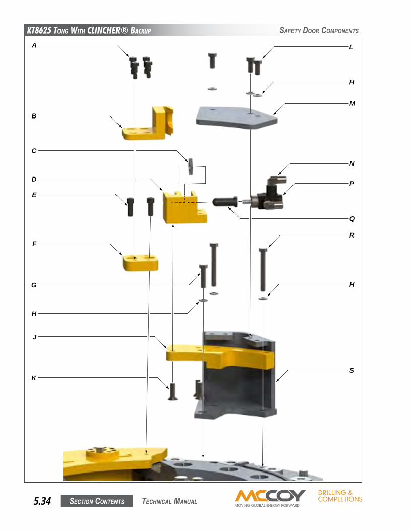
KT8625 Tong WiTh CLinChER® BaCKup
Section contentS5.34 technical Manual
Safety DooR coMPonentS
A
B
C
D
K
J
R
H
N
H
M
Q
E
F
G
H
L
P
S

KT8625 Tong WiTh CLinChER® BaCKup
Section contentS 5.35 technical Manual
Safety DooR coMPonentS
Item Type Description Qty Part NumberA Part 3/8”x1/2”ShoulderBolt,UNC 4 09-0125
B Part SafetyDoorLatchBlock 1 101-1104
C Part 15/16”ValveLockNut 1 09-0278
D Part SafetyDoorLatchBlock 1 101-1103
E Part 3/8”UNCx1”HexSocketHeadCapScrew 2 09-1738
F Part SafetyDoorLatchSpacer 1 101-1411
G Part 3/8”UNCx1-1/4”HexBolt 1 09-1048
H Part 3/8”CarbonSteelLockWasher 6 09-5106
J Part SafetyDoorLatchPlate 1 101-1410
K Part 3/8”UNCx1”HexSocketFlatCountersunkCapScrew 3 09-4046
L Part 3/8”UNCx3/4”HexBolt 4 09-1044
M Part SwitchGuardTopPlate 1 101-1474
N Part 1/4”NPT-JIC90degreeelbow2024-4-4 3 08-0284
P Part SafetyDoorSwitch 1 08-0337M
q Part LoadPlunger 1 AE12-306
R Part 3/8”UNCx3”HexBolt 2 09-1058
S Weldment SafetyDoorSwitchGuardWeldment 1 101-1475
CE-Marked tongs use the following parts in place of those in the previous table:Item Type Description Qty Part Number
A Part 3/8”x1/2”ShoulderBolt,UNC,SSDrilled 4 09-0125SSD
G Part 3/8”UNCx1-1/4”HexBolt,SSDrilled 1 09-1048SSD
L Part 3/8”UNCx3/4”HexBolt,SSDrilled 4 09-1044SSD
R Part 3/8”UNCx3”HexBolt,SSDrilled 2 09-1058SSD
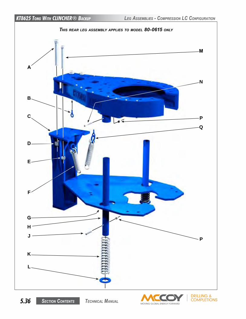
KT8625 Tong WiTh CLinChER® BaCKup
Section contentS5.36 technical Manual
leG aSSeMBlieS - coMPReSSion lc confiGuRation
THIS REAR LEg ASSEMBLy AppLIES TO MOdEL 80-0615 ONLy
A
B
C
D
E
H
J
L
K
F
M
N
P
Q
P
G
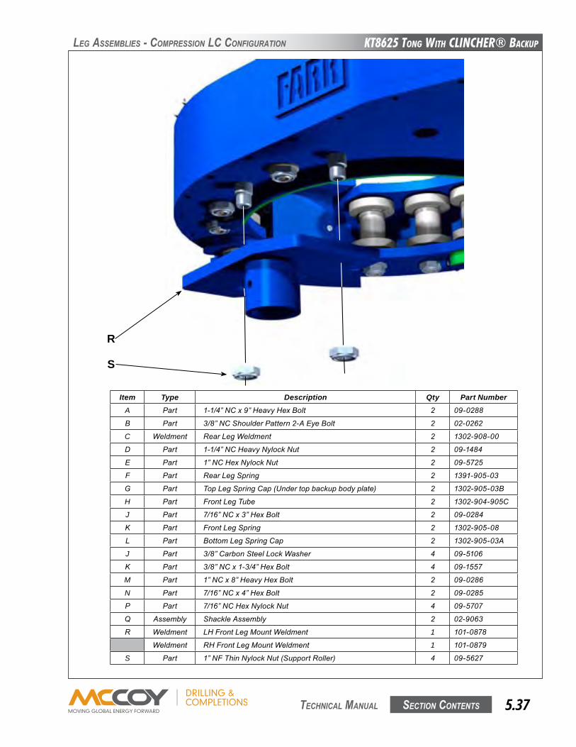
KT8625 Tong WiTh CLinChER® BaCKup
Section contentS 5.37 technical Manual
Item Type Description Qty Part NumberA Part 1-1/4”NCx9”HeavyHexBolt 2 09-0288
B Part 3/8”NCShoulderPattern2-AEyeBolt 2 02-0262
C Weldment RearLegWeldment 2 1302-908-00
D Part 1-1/4”NCHeavyNylockNut 2 09-1484
E Part 1”NCHexNylockNut 2 09-5725
F Part RearLegSpring 2 1391-905-03
G Part TopLegSpringCap(Undertopbackupbodyplate) 2 1302-905-03B
H Part FrontLegTube 2 1302-904-905C
J Part 7/16”NCx3”HexBolt 2 09-0284
K Part FrontLegSpring 2 1302-905-08
L Part BottomLegSpringCap 2 1302-905-03A
J Part 3/8”CarbonSteelLockWasher 4 09-5106
K Part 3/8”NCx1-3/4”HexBolt 4 09-1557
M Part 1”NCx8”HeavyHexBolt 2 09-0286
N Part 7/16”NCx4”HexBolt 2 09-0285
P Part 7/16”NCHexNylockNut 4 09-5707
q Assembly ShackleAssembly 2 02-9063
R Weldment LHFrontLegMountWeldment 1 101-0878
Weldment RHFrontLegMountWeldment 1 101-0879
S Part 1”NFThinNylockNut(SupportRoller) 4 09-5627
leG aSSeMBlieS - coMPReSSion lc confiGuRation
R
S
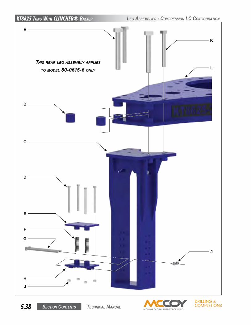
KT8625 Tong WiTh CLinChER® BaCKup
Section contentS5.38 technical Manual
leG aSSeMBlieS - coMPReSSion lc confiGuRation
A
B
C
D
E
F
G
H
J
K
L
J
THIS REAR LEg ASSEMBLy AppLIES
TO MOdEL 80-0615-6 ONLy
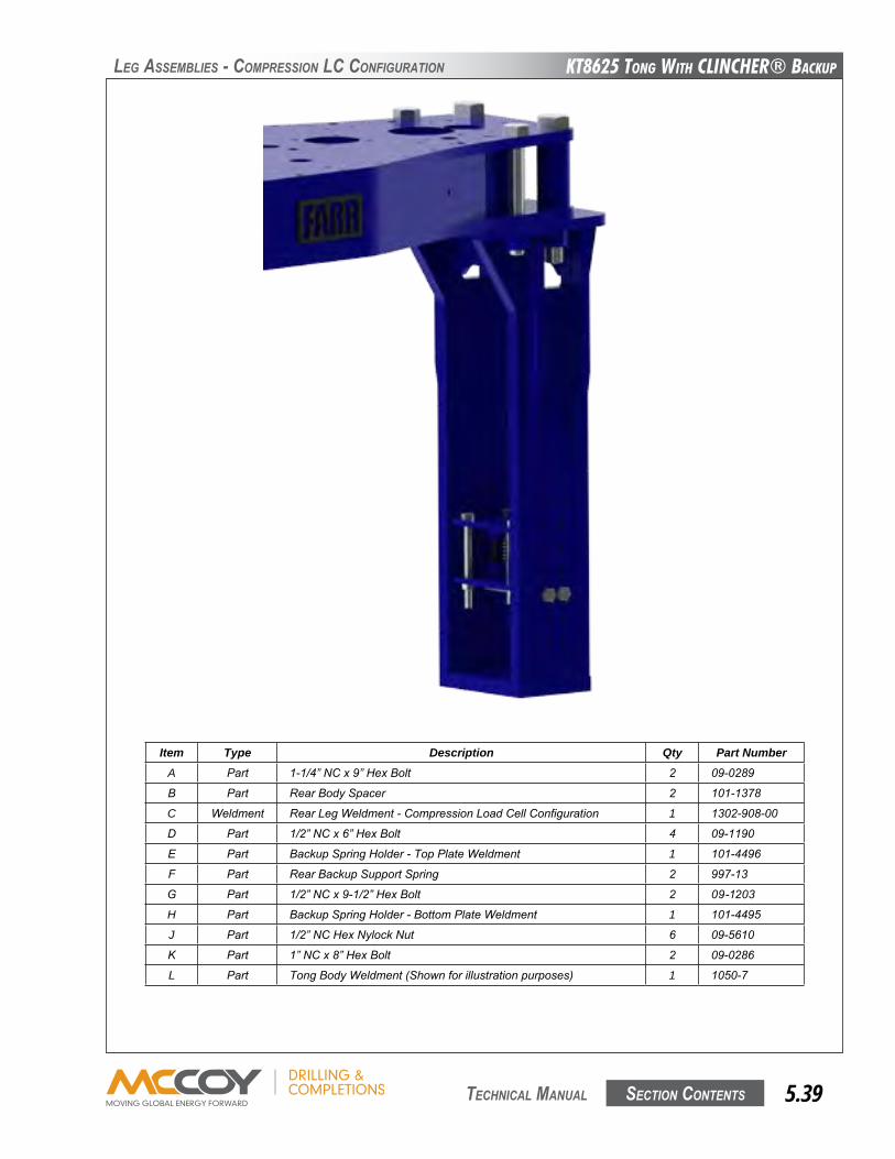
KT8625 Tong WiTh CLinChER® BaCKup
Section contentS 5.39 technical Manual
Item Type Description Qty Part NumberA Part 1-1/4”NCx9”HexBolt 2 09-0289
B Part RearBodySpacer 2 101-1378
C Weldment RearLegWeldment-CompressionLoadCellConfiguration 1 1302-908-00
D Part 1/2”NCx6”HexBolt 4 09-1190
E Part BackupSpringHolder-TopPlateWeldment 1 101-4496
F Part RearBackupSupportSpring 2 997-13
G Part 1/2”NCx9-1/2”HexBolt 2 09-1203
H Part BackupSpringHolder-BottomPlateWeldment 1 101-4495
J Part 1/2”NCHexNylockNut 6 09-5610
K Part 1”NCx8”HexBolt 2 09-0286
L Part TongBodyWeldment(Shownforillustrationpurposes) 1 1050-7
leG aSSeMBlieS - coMPReSSion lc confiGuRation
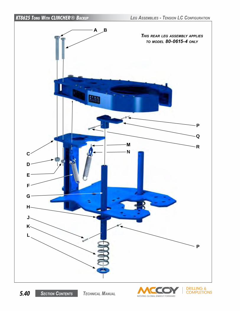
KT8625 Tong WiTh CLinChER® BaCKup
Section contentS5.40 technical Manual
leG aSSeMBlieS - tenSion lc confiGuRation
A B
D
F
Q
R
P
K
J
P
E
L
G
H
C NM
THIS REAR LEg ASSEMBLy AppLIESTO MOdEL 80-0615-4 ONLy
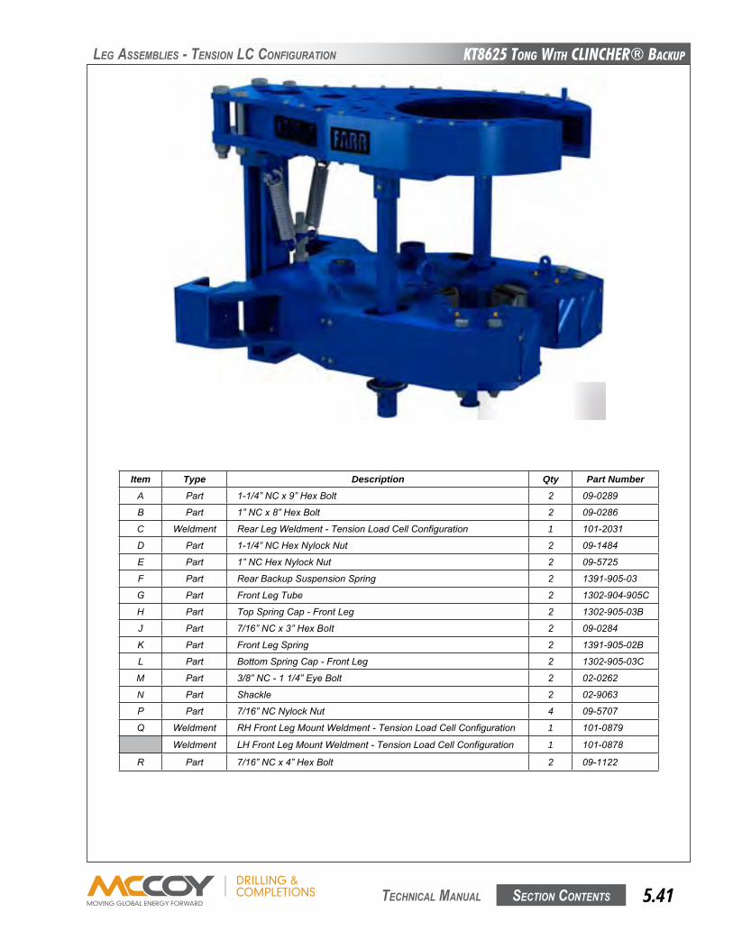
KT8625 Tong WiTh CLinChER® BaCKup
Section contentS 5.41 technical Manual
leG aSSeMBlieS - tenSion lc confiGuRation
Item Type Description Qty Part NumberA Part 1-1/4”NCx9”HexBolt 2 09-0289
B Part 1”NCx8”HexBolt 2 09-0286
C Weldment RearLegWeldment-TensionLoadCellConfiguration 1 101-2031
D Part 1-1/4”NCHexNylockNut 2 09-1484
E Part 1”NCHexNylockNut 2 09-5725
F Part RearBackupSuspensionSpring 2 1391-905-03
G Part FrontLegTube 2 1302-904-905C
H Part TopSpringCap-FrontLeg 2 1302-905-03B
J Part 7/16”NCx3”HexBolt 2 09-0284
K Part FrontLegSpring 2 1391-905-02B
L Part BottomSpringCap-FrontLeg 2 1302-905-03C
M Part 3/8”NC-11/4”EyeBolt 2 02-0262
N Part Shackle 2 02-9063
P Part 7/16”NCNylockNut 4 09-5707
q Weldment RHFrontLegMountWeldment-TensionLoadCellConfiguration 1 101-0879
Weldment LHFrontLegMountWeldment-TensionLoadCellConfiguration 1 101-0878
R Part 7/16”NCx4”HexBolt 2 09-1122
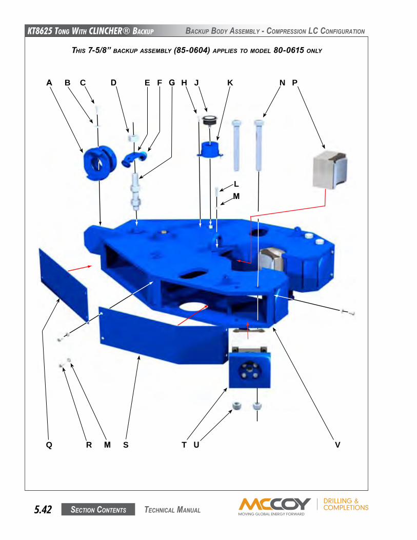
KT8625 Tong WiTh CLinChER® BaCKup
Section contentS5.42 technical Manual
BacKuP BoDy aSSeMBly - coMPReSSion lc confiGuRation
THIS 7-5/8” BACKUp ASSEMBLy (85-0604) AppLIES TO MOdEL 80-0615 ONLy
A B E F K
L
JC D HG
RQ TM S
N
M
P
U V
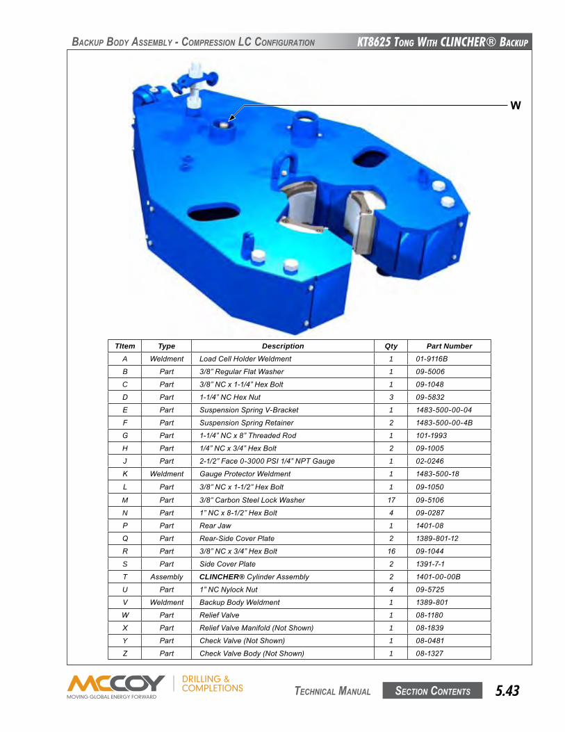
KT8625 Tong WiTh CLinChER® BaCKup
Section contentS 5.43 technical Manual
TItem Type Description Qty Part NumberA Weldment LoadCellHolderWeldment 1 01-9116B
B Part 3/8”RegularFlatWasher 1 09-5006
C Part 3/8”NCx1-1/4”HexBolt 1 09-1048
D Part 1-1/4”NCHexNut 3 09-5832
E Part SuspensionSpringV-Bracket 1 1483-500-00-04
F Part SuspensionSpringRetainer 2 1483-500-00-4B
G Part 1-1/4”NCx8”ThreadedRod 1 101-1993
H Part 1/4”NCx3/4”HexBolt 2 09-1005
J Part 2-1/2”Face0-3000PSI1/4”NPTGauge 1 02-0246
K Weldment GaugeProtectorWeldment 1 1483-500-18
L Part 3/8”NCx1-1/2”HexBolt 1 09-1050
M Part 3/8”CarbonSteelLockWasher 17 09-5106
N Part 1”NCx8-1/2”HexBolt 4 09-0287
P Part RearJaw 1 1401-08
q Part Rear-SideCoverPlate 2 1389-801-12
R Part 3/8”NCx3/4”HexBolt 16 09-1044
S Part SideCoverPlate 2 1391-7-1
T Assembly CLINCHER®CylinderAssembly 2 1401-00-00B
U Part 1”NCNylockNut 4 09-5725
V Weldment BackupBodyWeldment 1 1389-801
W Part ReliefValve 1 08-1180
X Part ReliefValveManifold(NotShown) 1 08-1839
Y Part CheckValve(NotShown) 1 08-0481
z Part CheckValveBody(NotShown) 1 08-1327
BacKuP BoDy aSSeMBly - coMPReSSion lc confiGuRation
W
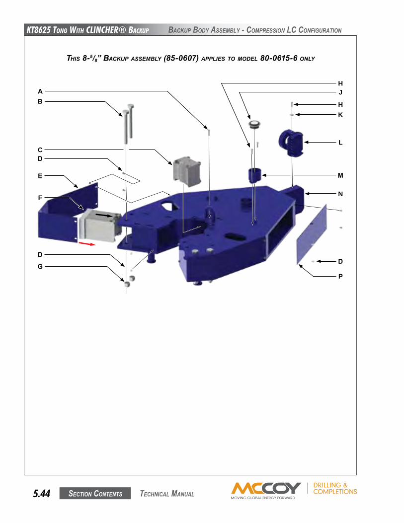
KT8625 Tong WiTh CLinChER® BaCKup
Section contentS5.44 technical Manual
BacKuP BoDy aSSeMBly - coMPReSSion lc confiGuRation
THIS 8-5/8” BACKUp ASSEMBLy (85-0607) AppLIES TO MOdEL 80-0615-6 ONLy
AB
CD
G
E
F
D
HJ
HK
L
M
N
P
D
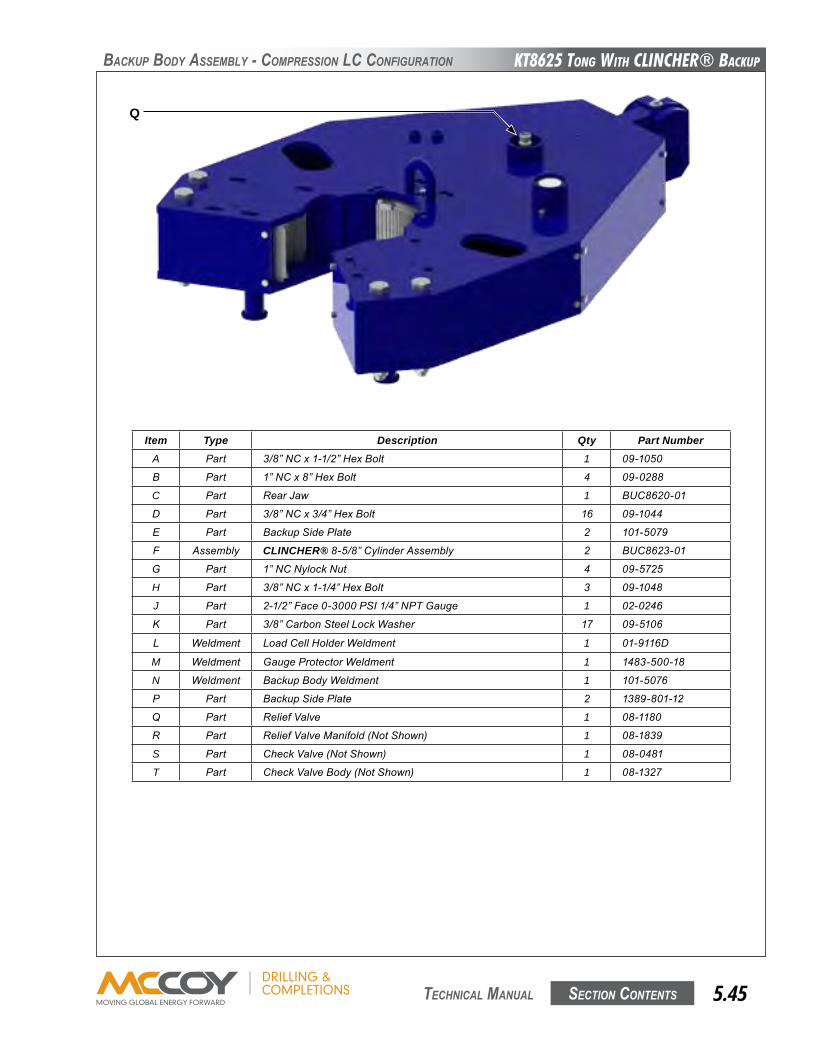
KT8625 Tong WiTh CLinChER® BaCKup
Section contentS 5.45 technical Manual
BacKuP BoDy aSSeMBly - coMPReSSion lc confiGuRation
Item Type Description Qty Part NumberA Part 3/8”NCx1-1/2”HexBolt 1 09-1050
B Part 1”NCx8”HexBolt 4 09-0288
C Part RearJaw 1 BUC8620-01
D Part 3/8”NCx3/4”HexBolt 16 09-1044
E Part BackupSidePlate 2 101-5079
F Assembly CLINCHER®8-5/8”CylinderAssembly 2 BUC8623-01
G Part 1”NCNylockNut 4 09-5725
H Part 3/8”NCx1-1/4”HexBolt 3 09-1048
J Part 2-1/2”Face0-3000PSI1/4”NPTGauge 1 02-0246
K Part 3/8”CarbonSteelLockWasher 17 09-5106
L Weldment LoadCellHolderWeldment 1 01-9116D
M Weldment GaugeProtectorWeldment 1 1483-500-18
N Weldment BackupBodyWeldment 1 101-5076
P Part BackupSidePlate 2 1389-801-12
q Part ReliefValve 1 08-1180
R Part ReliefValveManifold(NotShown) 1 08-1839
S Part CheckValve(NotShown) 1 08-0481
T Part CheckValveBody(NotShown) 1 08-1327
Q
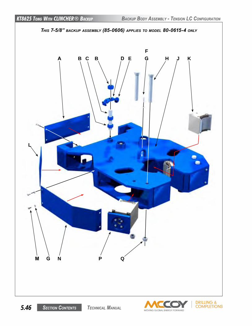
KT8625 Tong WiTh CLinChER® BaCKup
Section contentS5.46 technical Manual
BacKuP BoDy aSSeMBly - tenSion lc confiGuRation
THIS 7-5/8” BACKUp ASSEMBLy (85-0606) AppLIES TO MOdEL 80-0615-4 ONLy
A B D E J KHC
G
L
M
B
QN P
GF
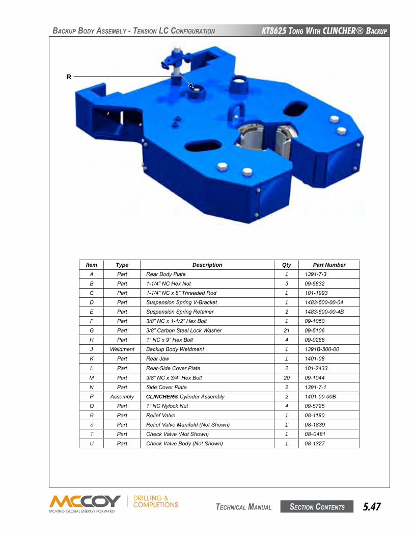
KT8625 Tong WiTh CLinChER® BaCKup
Section contentS 5.47 technical Manual
BacKuP BoDy aSSeMBly - tenSion lc confiGuRation
Item Type Description Qty Part NumberA Part RearBodyPlate 1 1391-7-3
B Part 1-1/4”NCHexNut 3 09-5832
C Part 1-1/4”NCx8”ThreadedRod 1 101-1993
D Part SuspensionSpringV-Bracket 1 1483-500-00-04
E Part SuspensionSpringRetainer 2 1483-500-00-4B
F Part 3/8”NCx1-1/2”HexBolt 1 09-1050
G Part 3/8”CarbonSteelLockWasher 21 09-5106
H Part 1”NCx9”HexBolt 4 09-0288
J Weldment BackupBodyWeldment 1 1391B-500-00
K Part RearJaw 1 1401-08
L Part Rear-SideCoverPlate 2 101-2433
M Part 3/8”NCx3/4”HexBolt 20 09-1044
N Part SideCoverPlate 2 1391-7-1
P Assembly CLINCHER®CylinderAssembly 2 1401-00-00B
q Part 1”NCNylockNut 4 09-5725
r Part ReliefValve 1 08-1180
s Part ReliefValveManifold(NotShown) 1 08-1839
t Part CheckValve(NotShown) 1 08-0481
u Part CheckValveBody(NotShown) 1 08-1327
R
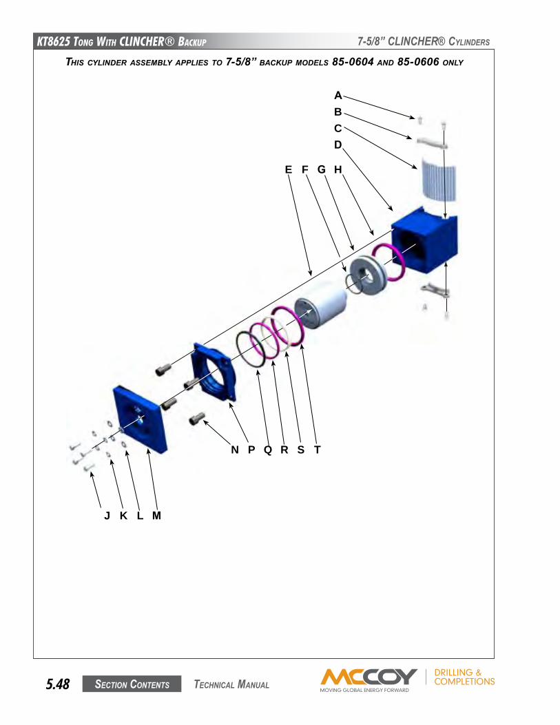
KT8625 Tong WiTh CLinChER® BaCKup
Section contentS5.48 technical Manual
7-5/8” clincheR® cylinDeRS
THIS CyLINdER ASSEMBLy AppLIES TO 7-5/8” BACKUp MOdELS 85-0604 ANd 85-0606 ONLy
A
K
D
G
J L
H
CB
P Q
E F
M
N R S T
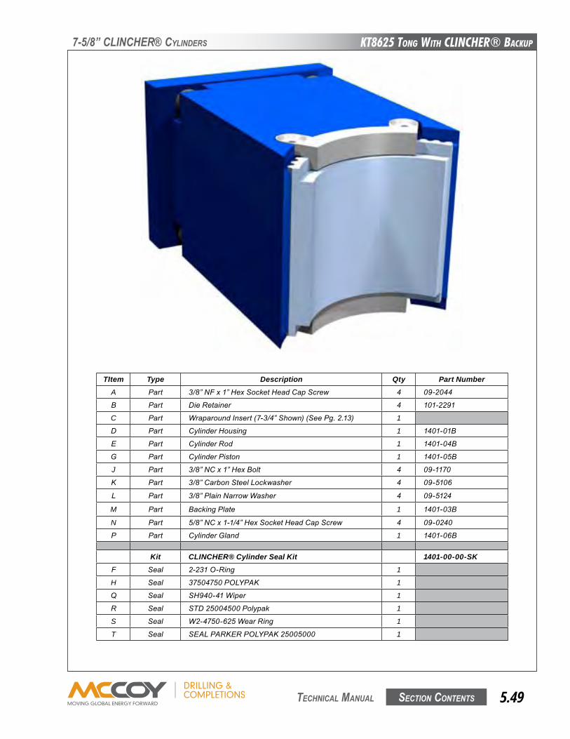
KT8625 Tong WiTh CLinChER® BaCKup
Section contentS 5.49 technical Manual
7-5/8” clincheR® cylinDeRS
TItem Type Description Qty Part NumberA Part 3/8”NFx1”HexSocketHeadCapScrew 4 09-2044
B Part DieRetainer 4 101-2291
C Part WraparoundInsert(7-3/4”Shown)(SeePg.2.13) 1
D Part CylinderHousing 1 1401-01B
E Part CylinderRod 1 1401-04B
G Part CylinderPiston 1 1401-05B
J Part 3/8”NCx1”HexBolt 4 09-1170
K Part 3/8”CarbonSteelLockwasher 4 09-5106
L Part 3/8”PlainNarrowWasher 4 09-5124
M Part BackingPlate 1 1401-03B
N Part 5/8”NCx1-1/4”HexSocketHeadCapScrew 4 09-0240
P Part CylinderGland 1 1401-06B
Kit CLINCHER® Cylinder Seal Kit 1401-00-00-SKF Seal 2-231O-Ring 1
H Seal 37504750POLYPAK 1
q Seal SH940-41Wiper 1
R Seal STD25004500Polypak 1
S Seal W2-4750-625WearRing 1
T Seal SEALPARKERPOLYPAK25005000 1
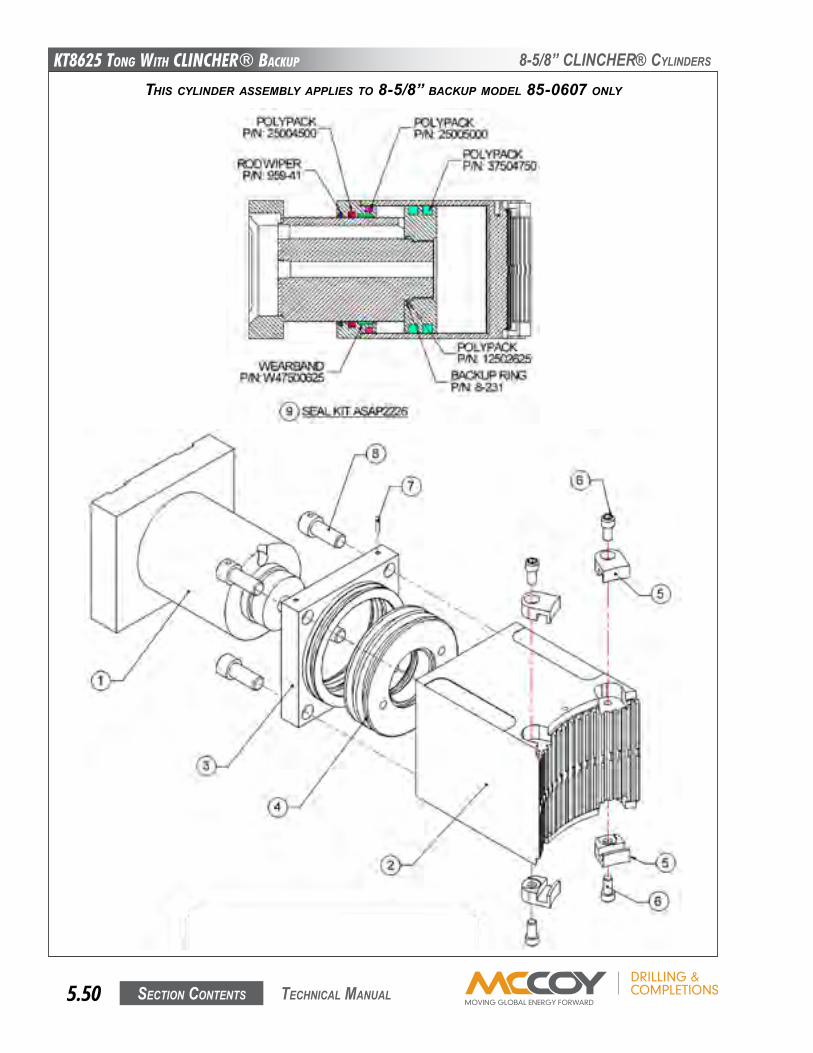
KT8625 Tong WiTh CLinChER® BaCKup
Section contentS5.50 technical Manual
THIS CyLINdER ASSEMBLy AppLIES TO 8-5/8” BACKUp MOdEL 85-0607 ONLy
8-5/8” clincheR® cylinDeRS
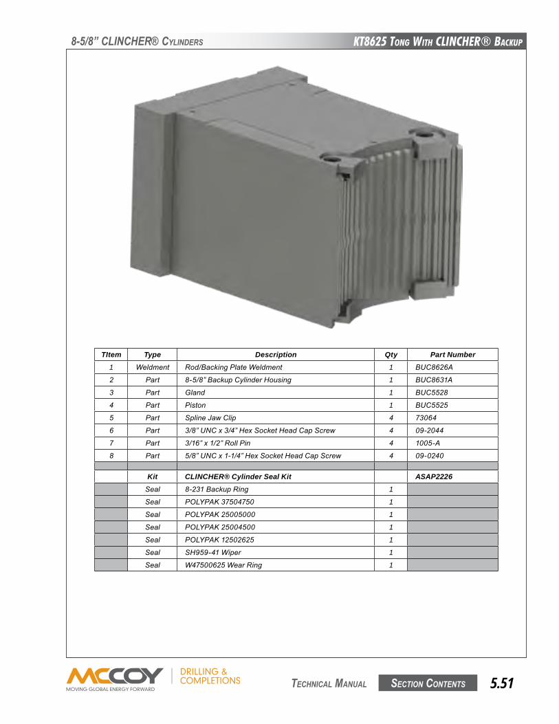
KT8625 Tong WiTh CLinChER® BaCKup
Section contentS 5.51 technical Manual
TItem Type Description Qty Part Number1 Weldment Rod/BackingPlateWeldment 1 BUC8626A
2 Part 8-5/8”BackupCylinderHousing 1 BUC8631A
3 Part Gland 1 BUC5528
4 Part Piston 1 BUC5525
5 Part SplineJawClip 4 73064
6 Part 3/8”UNCx3/4”HexSocketHeadCapScrew 4 09-2044
7 Part 3/16”x1/2”RollPin 4 1005-A
8 Part 5/8”UNCx1-1/4”HexSocketHeadCapScrew 4 09-0240
Kit CLINCHER® Cylinder Seal Kit ASAP2226Seal 8-231BackupRing 1
Seal POLYPAK37504750 1
Seal POLYPAK25005000 1
Seal POLYPAK25004500 1
Seal POLYPAK12502625 1
Seal SH959-41Wiper 1
Seal W47500625WearRing 1
8-5/8” clincheR® cylinDeRS
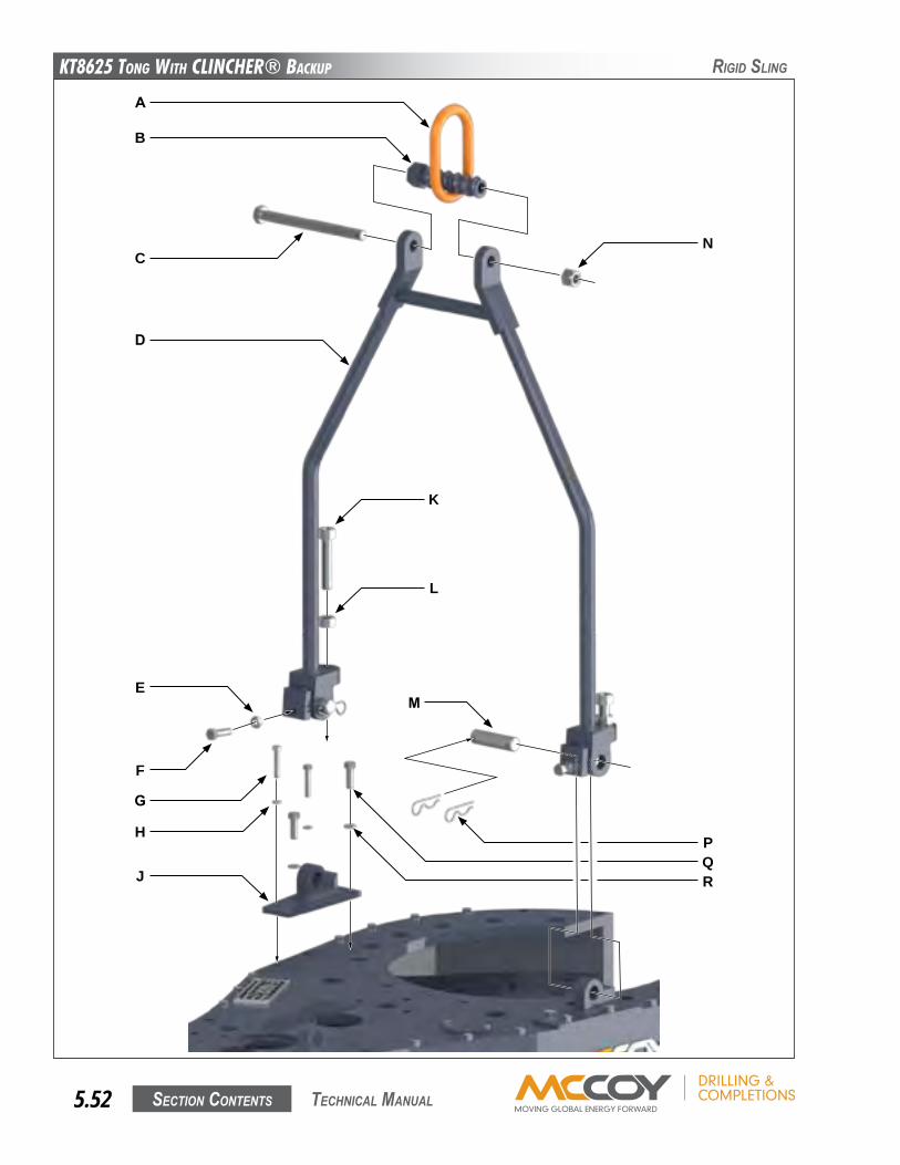
KT8625 Tong WiTh CLinChER® BaCKup
Section contentS5.52 technical Manual
RiGiD SlinG
A
B
C
D
E
J
K
L
QP
F
G
H
N
R
M
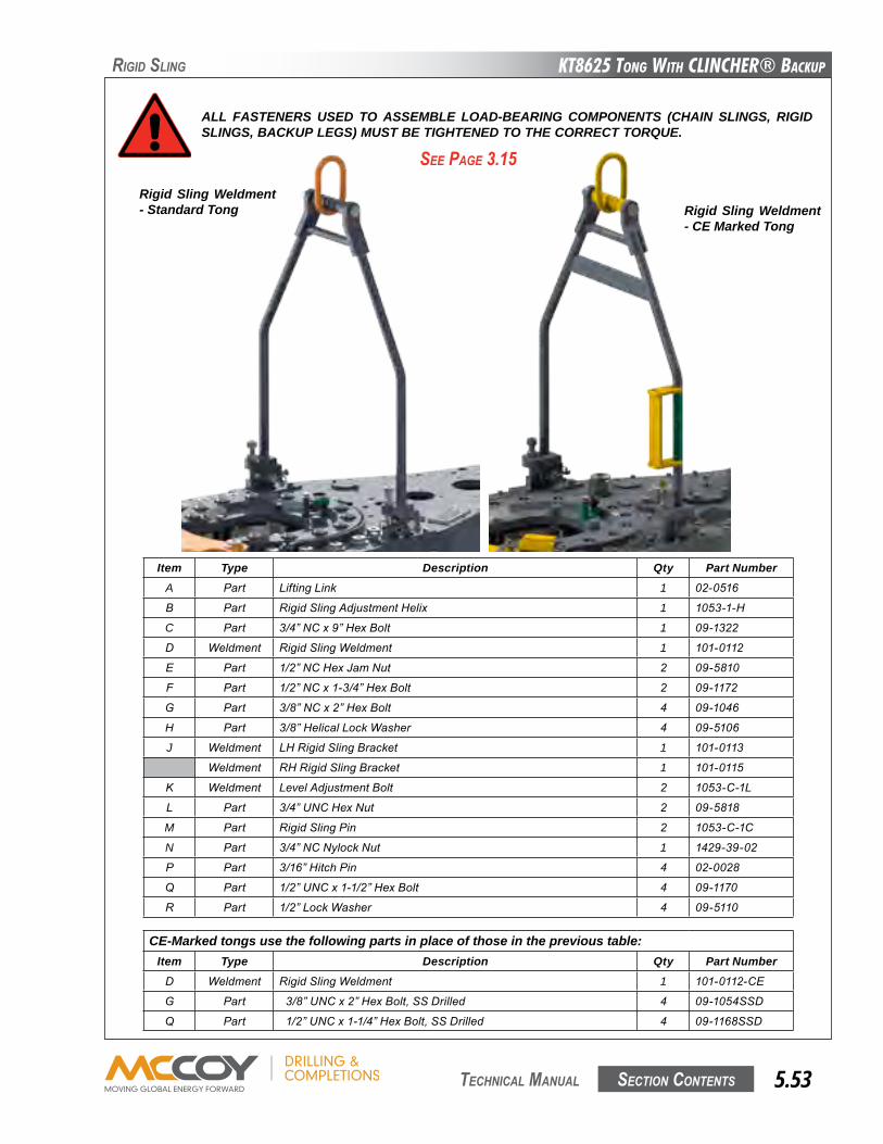
KT8625 Tong WiTh CLinChER® BaCKup
Section contentS 5.53 technical Manual
ALL FASTENERS USED TO ASSEMBLE LOAD-BEARING COMPONENTS (CHAIN SLINGS, RIGID SLINGS, BACKUP LEGS) MUST BE TIGHTENED TO THE CORRECT TORQUE.
Item Type Description Qty Part NumberA Part LiftingLink 1 02-0516
B Part RigidSlingAdjustmentHelix 1 1053-1-H
C Part 3/4”NCx9”HexBolt 1 09-1322
D Weldment RigidSlingWeldment 1 101-0112
E Part 1/2”NCHexJamNut 2 09-5810
F Part 1/2”NCx1-3/4”HexBolt 2 09-1172
G Part 3/8”NCx2”HexBolt 4 09-1046
H Part 3/8”HelicalLockWasher 4 09-5106
J Weldment LHRigidSlingBracket 1 101-0113
Weldment RHRigidSlingBracket 1 101-0115
K Weldment LevelAdjustmentBolt 2 1053-C-1L
L Part 3/4”UNCHexNut 2 09-5818
M Part RigidSlingPin 2 1053-C-1C
N Part 3/4”NCNylockNut 1 1429-39-02
P Part 3/16”HitchPin 4 02-0028
q Part 1/2”UNCx1-1/2”HexBolt 4 09-1170
R Part 1/2”LockWasher 4 09-5110
RiGiD SlinG
See PaGe 3.15
CE-Marked tongs use the following parts in place of those in the previous table:Item Type Description Qty Part NumberD Weldment RigidSlingWeldment 1 101-0112-CE
G Part 3/8”UNCx2”HexBolt,SSDrilled 4 09-1054SSD
q Part 1/2”UNCx1-1/4”HexBolt,SSDrilled 4 09-1168SSD
Rigid Sling Weldment - Standard Tong Rigid Sling Weldment
- CE Marked Tong
This page intentionallyleft blank
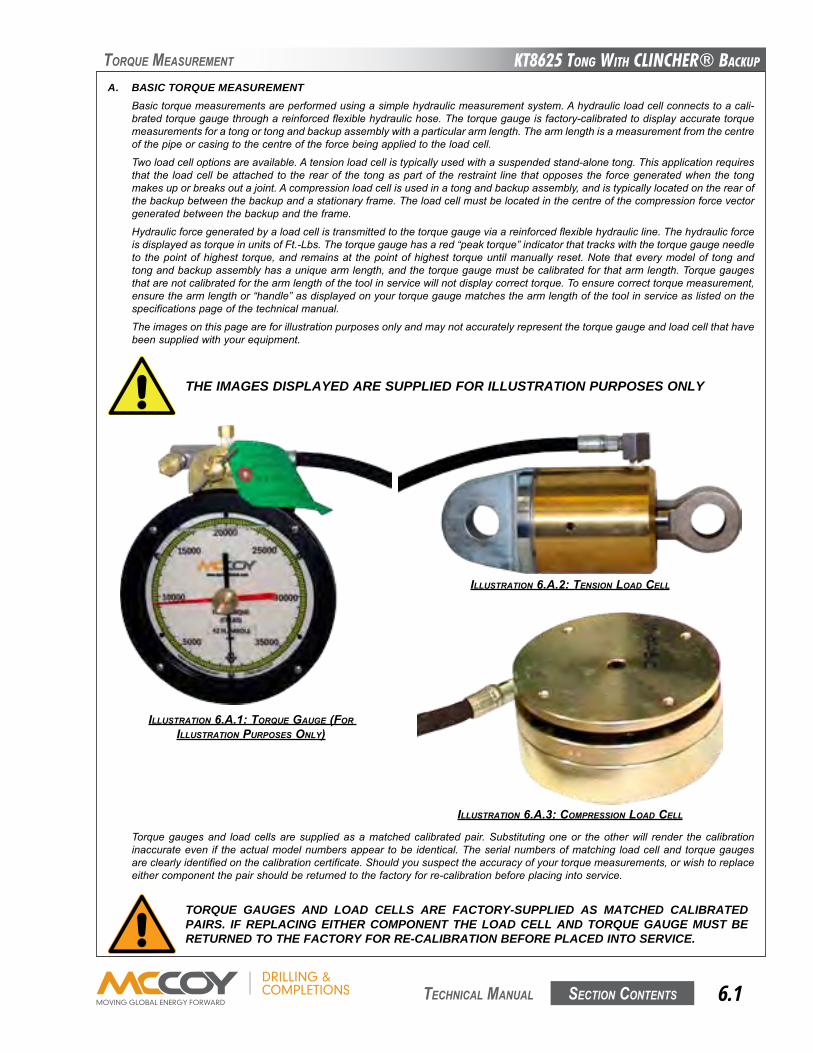
KT8625 Tong WiTh CLinChER® BaCKup
Section contentS 6.1 technical Manual
toRque MeaSuReMent
A. BASIC TORQUE MEASUREMENT Basictorquemeasurementsareperformedusingasimplehydraulicmeasurementsystem.Ahydraulicloadcellconnectstoacali-bratedtorquegaugethroughareinforcedflexiblehydraulichose.Thetorquegaugeisfactory-calibratedtodisplayaccuratetorquemeasurementsforatongortongandbackupassemblywithaparticulararmlength.Thearmlengthisameasurementfromthecentreofthepipeorcasingtothecentreoftheforcebeingappliedtotheloadcell.
Twoloadcelloptionsareavailable.Atensionloadcellistypicallyusedwithasuspendedstand-alonetong.Thisapplicationrequiresthat the loadcellbeattachedto therearof the tongaspartof therestraint line thatopposesthe forcegeneratedwhenthe tongmakesuporbreaksoutajoint.Acompressionloadcellisusedinatongandbackupassembly,andistypicallylocatedontherearofthebackupbetweenthebackupandastationaryframe.Theloadcellmustbelocatedinthecentreofthecompressionforcevectorgeneratedbetweenthebackupandtheframe.
Hydraulicforcegeneratedbyaloadcellistransmittedtothetorquegaugeviaareinforcedflexiblehydraulicline.ThehydraulicforceisdisplayedastorqueinunitsofFt.-Lbs.Thetorquegaugehasared“peaktorque”indicatorthattrackswiththetorquegaugeneedleto thepointofhighest torque,andremainsat thepointofhighest torqueuntilmanuallyreset.Note thateverymodelof tongandtongandbackupassemblyhasauniquearmlength,andthetorquegaugemustbecalibratedforthatarmlength.Torquegaugesthatarenotcalibratedforthearmlengthofthetoolinservicewillnotdisplaycorrecttorque.Toensurecorrecttorquemeasurement,ensurethearmlengthor“handle”asdisplayedonyourtorquegaugematchesthearmlengthofthetoolinserviceaslistedonthespecificationspageofthetechnicalmanual.
Theimagesonthispageareforillustrationpurposesonlyandmaynotaccuratelyrepresentthetorquegaugeandloadcellthathavebeensuppliedwithyourequipment.
ILLUSTRATION 6.A.1: TORqUE gAUgE (FOR ILLUSTRATION pURpOSES ONLy)
ILLUSTRATION 6.A.3: COMpRESSION LOAd CELL
THE IMAGES DISPLAYED ARE SUPPLIED FOR ILLUSTRATION PURPOSES ONLY
TORQUE GAUGES AND LOAD CELLS ARE FACTORY-SUPPLIED AS MATCHED CALIBRATED PAIRS. IF REPLACING EITHER COMPONENT THE LOAD CELL AND TORQUE GAUGE MUST BE RETURNED TO THE FACTORY FOR RE-CALIBRATION BEFORE PLACED INTO SERVICE.
Torquegaugesand loadcellsaresuppliedasamatchedcalibratedpair.Substitutingoneor theotherwill render thecalibrationinaccurateeven if theactualmodelnumbersappear tobe identical.Theserialnumbersofmatching loadcellandtorquegaugesareclearlyidentifiedonthecalibrationcertificate.Shouldyoususpecttheaccuracyofyourtorquemeasurements,orwishtoreplaceeithercomponentthepairshouldbereturnedtothefactoryforre-calibrationbeforeplacingintoservice.
ILLUSTRATION 6.A.2: TENSION LOAd CELL
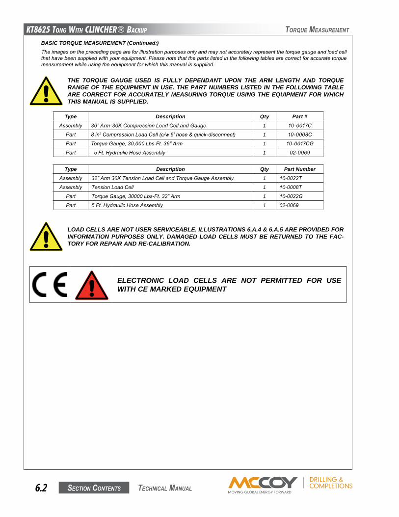
KT8625 Tong WiTh CLinChER® BaCKup
Section contentS6.2 technical Manual
Type Description Qty Part #Assembly 36”Arm-30KCompressionLoadCellandGauge 1 10-0017C
Part 8in2CompressionLoadCell(c/w5’hose&quick-disconnect) 1 10-0008C
Part TorqueGauge,30,000Lbs-Ft.36”Arm 1 10-0017CG
Part 5Ft.HydraulicHoseAssembly 1 02-0069
Type Description Qty Part NumberAssembly 32”Arm30KTensionLoadCellandTorqueGaugeAssembly 1 10-0022T
Assembly TensionLoadCell 1 10-0008T
Part TorqueGauge,30000Lbs-Ft.32”Arm 1 10-0022G
Part 5Ft.HydraulicHoseAssembly 1 02-0069
THE TORQUE GAUGE USED IS FULLY DEPENDANT UPON THE ARM LENGTH AND TORQUE RANGE OF THE EQUIPMENT IN USE. THE PART NUMBERS LISTED IN THE FOLLOWING TABLE ARE CORRECT FOR ACCURATELY MEASURING TORQUE USING THE EQUIPMENT FOR WHICH THIS MANUAL IS SUPPLIED.
BASIC TORQUE MEASUREMENT (Continued:)Theimagesontheprecedingpageareforillustrationpurposesonlyandmaynotaccuratelyrepresentthetorquegaugeandloadcellthathavebeensuppliedwithyourequipment.Pleasenotethatthepartslistedinthefollowingtablesarecorrectforaccuratetorquemeasurementwhileusingtheequipmentforwhichthismanualissupplied.
toRque MeaSuReMent
LOAD CELLS ARE NOT USER SERVICEABLE. ILLUSTRATIONS 6.A.4 & 6.A.5 ARE PROVIDED FOR INFORMATION PURPOSES ONLY. DAMAGED LOAD CELLS MUST BE RETURNED TO THE FAC-TORY FOR REPAIR AND RE-CALIBRATION.
ELECTRONIC LOAD CELLS ARE NOT PERMITTED FOR USE WITH CE MARKED EQUIPMENT
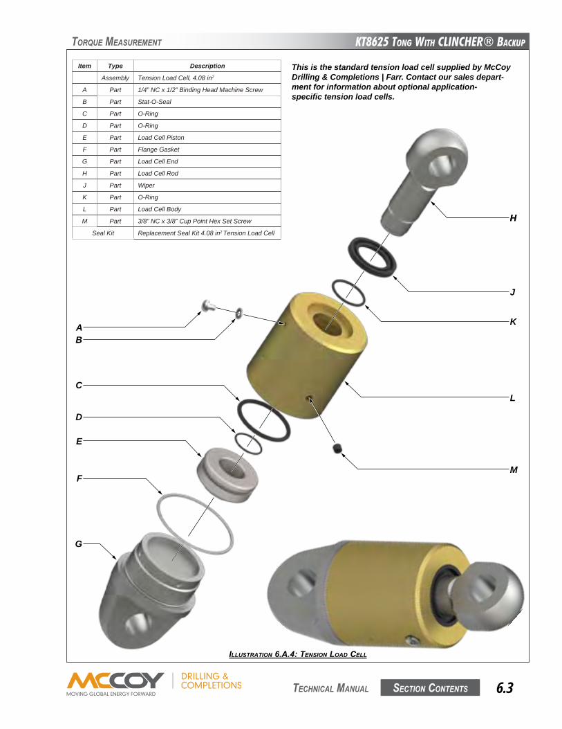
KT8625 Tong WiTh CLinChER® BaCKup
Section contentS 6.3 technical Manual
ILLUSTRATION 6.A.4: TENSION LOAd CELL
toRque MeaSuReMent
This is the standard tension load cell supplied by McCoy Drilling & Completions | Farr. Contact our sales depart-ment for information about optional application-specific tension load cells.
AB
C
D
E
F
G
HH
J
K
L
M
Item Type Description
Assembly Tension Load Cell, 4.08 in2
A Part 1/4” NC x 1/2” Binding Head Machine Screw
B Part Stat-O-Seal
C Part O-Ring
D Part O-Ring
E Part Load Cell Piston
F Part Flange Gasket
G Part Load Cell End
H Part Load Cell Rod
J Part Wiper
K Part O-Ring
L Part Load Cell Body
M Part 3/8” NC x 3/8” Cup Point Hex Set Screw
Seal Kit Replacement Seal Kit 4.08 in2 Tension Load Cell
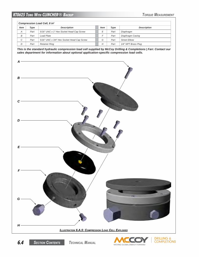
KT8625 Tong WiTh CLinChER® BaCKup
Section contentS6.4 technical Manual
toRque MeaSuReMent
ILLUSTRATION 6.A.5: COMpRESSION LOAd CELL ExpLOdEd
This is the standard hydraulic compression load cell supplied by McCoy Drilling & Completions | Farr. Contact our sales department for information about optional application-specific compression load cells.
A
B
C
D
E
F
G
H
Compression Load Cell, 8 in2
Item Type Description Item Type Description
A Part 5/16” UNC x 1” Hex Socket Head Cap Screw E Part Diaphragm
B Part Load Plate F Part Diaphragm Casing
C Part 5/16” UNC x 3/4” Hex Socket Head Cap Screw G Part Street Elbow
D Part Retainer Ring H Part 1/4” NPT Brass Plug
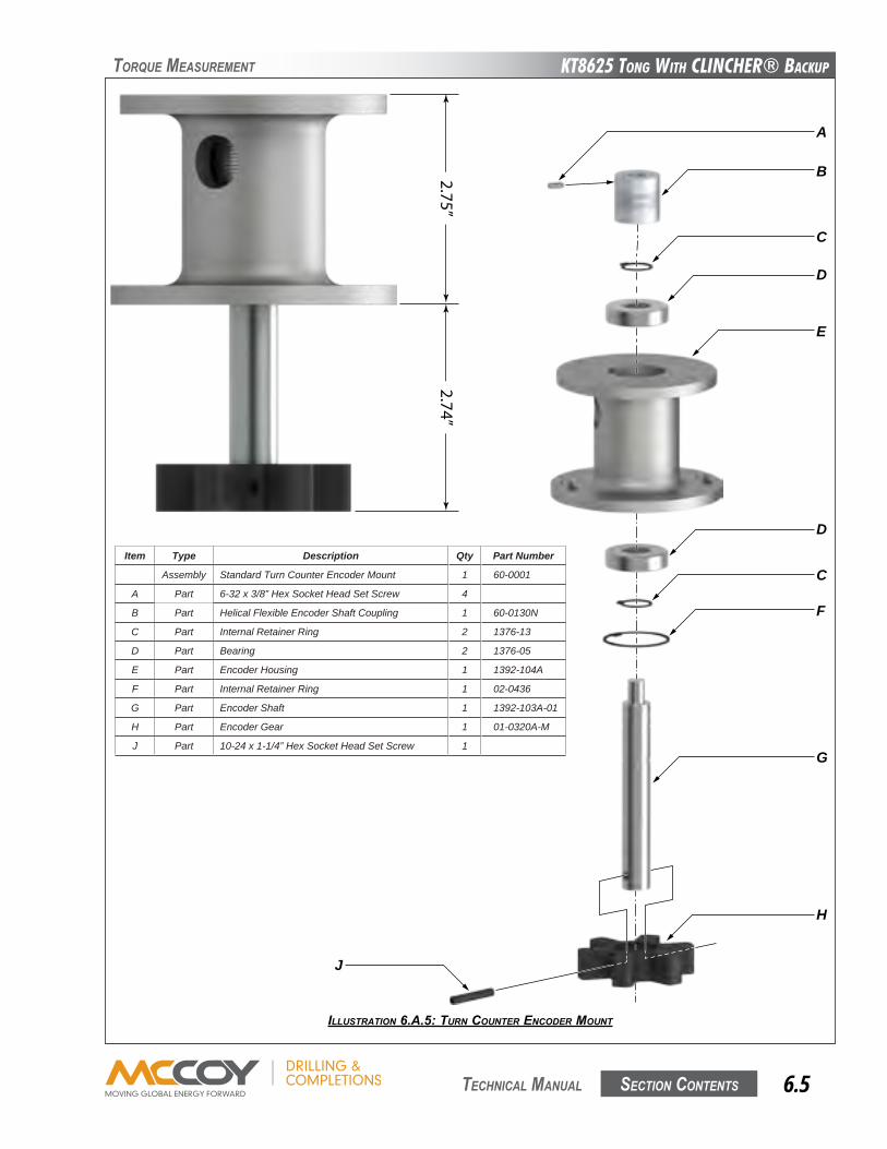
KT8625 Tong WiTh CLinChER® BaCKup
Section contentS 6.5 technical Manual
ILLUSTRATION 6.A.5: TURN COUNTER ENCOdER MOUNT
toRque MeaSuReMent
2.74”2.75”
J
A
B
C
D
E
D
C
F
G
H
Item Type Description Qty Part Number
Assembly Standard Turn Counter Encoder Mount 1 60-0001
A Part 6-32 x 3/8” Hex Socket Head Set Screw 4
B Part Helical Flexible Encoder Shaft Coupling 1 60-0130N
C Part Internal Retainer Ring 2 1376-13
D Part Bearing 2 1376-05
E Part Encoder Housing 1 1392-104A
F Part Internal Retainer Ring 1 02-0436
G Part Encoder Shaft 1 1392-103A-01
H Part Encoder Gear 1 01-0320A-M
J Part 10-24 x 1-1/4” Hex Socket Head Set Screw 1
KT8625 Tong WiTh CLinChER® BaCKup
Section contentS6.6 technical Manual
toRque MeaSuReMent
B. TROUBLESHOOTINGUndernormaloperatingconditions,andwithpropermaintenance,thetorquegaugeandloadcellsystemaredesignedtogivelastingtrouble-freeperformance.Faultyindicationonthegaugewillveryoftendefineafaultwithinthegauge.
1. Symptom: No indication on gauge.
PossibleProblem: Obstructioninhydraulichose.
Solutions: Checkhydraulichoseforkinks. Replacehydraulichose.
PossibleProblem: Lossofhydraulicfluid.
Solution: Rechargehydraulicfluid(seeSection6.C).NOTE:Ensureanybreachesinthehydraulicsystem betweentheloadcellandtorquegaugearerepairedtopreventfurtherfluidloss.
PossibleProblem: Internalmechanismoftorquegaugeisdamaged.
Solution: Replacegauge.
2. Symptom: Gauge indication unexpectedly high.
PossibleProblem: Excessivehydraulicfluid.
Solutions: Completelydrainhydraulicfluidfromtorquegauge/loadcellsystem.Rechargefollowingthe procedureinSection6.C.
PossibleProblem: Internalmechanismofgaugeisdamaged.
Solution: Replacegauge.
PossibleProblem: Incorrecttorquegaugeinuse(notpartoftheoriginaltorquegauge/loadcellpair).
Solution: Replacegaugewithgaugeproperlycalibratedfortheloadcellinservice.
3. Symptom: Gauge indication unexpectedly low
PossibleProblem: Insufficienthydraulicfluid.
Solution: Rechargehydraulicfluid(seeSection6.C).NOTE:Ensureanybreachesinthehydraulicsystem betweentheloadcellandtorquegaugearerepairedtopreventfurtherfluidloss.
PossibleProblem: Obstructioninhydraulichose.
Solutions: Checkhydraulichoseforkinks.
Replacehydraulichose.
PossibleProblem: Snublinenotatright-angletotonghandle.
Solution: Checkangleofsnublineandcorrectifnecessary.
PossibleProblem: Internalmechanismofgaugeisdamaged.
Solution: Replacegauge.
PossibleProblem: Incorrecttorquegaugeinuse(notpartoftheoriginaltorquegauge/loadcellpair).
Solution: Replacegaugewithgaugeproperlycalibratedfortheloadcellinservice.
4. Symptom: Gauge indication is erratic or sluggish
PossibleProblem: Insufficienthydraulicfluidintorquemeasurementsection.
Solution: Rechargehydraulicfluid(seeSection6.C).NOTE:Ensureanybreachesinthehydraulicsystem betweentheloadcellandtorquegaugearerepairedtopreventfurtherfluidloss.
PossibleProblem: Lossofdampingfluidintorquegauge.
Solution: Topuporrefilldampingfluid(NOTE:Ensureleakagepointsingaugeareidentifiedandrepaired topreventfurtherlossofdampingfluid).
PossibleProblem: Airbubblesinhydraulicfluidinthetorquemeasurementsystem.
Solution: Bleedairfromloadcellandtorquegaugeandtopupfluid(ifnecessary)asperSection6.C.
PossibleProblem: Internalmechanismofgaugeisdamaged.
Solution: Replacegauge.
IFTROUBLESHOOTINGREVEALSTHATTHEREISINSUFFICIENTFLUIDINTHESYSTEM,BEFORERECHARGING,CHECKTHATALLSYSTEMCOMPONENTSAREFREEFROMDAMAGE.THISWILLENSURETHATFLUIDLOSSWILLNOTCONTINUEAFTERRELOADING
KT8625 Tong WiTh CLinChER® BaCKup
Section contentS 6.7 technical Manual
toRque MeaSuReMent
C. PERIODIC INSPECTION AND MAINTENANCE
MAINTAIN GREATER-THAN HALF FULL FLUID LEVEL IN THE HAND PUMP BOWL TO AVOID PUMPING AIR INTO THE SYSTEM. DO NOT ALLOW THE LEVEL TO FALL BELOW ONE-HALF FULL
UN-CONTAINED SPILLAGE OF THE HYDRAULIC FLUID IN THIS SYSTEM MAY CONTRAVENE GOVERNMENTAL ENVIRONMENTAL REGULATIONS, OR THE ENVIRONMENTAL REGULATIONS AND POLICIES OF YOUR COMPANY. FARR CANADA CORP. HIGHLY RECOMMENDS PLACING YOUR LOAD CELL IN A CONTAINMENT BASIN BEFORE PROCEEDING WITH THE BLEEDING & REFILLING PROCESS.
d. FillhandpumpbowlwithW15/16hydraulicfluid.
e. RemovetheventplugscrewandStat-O-Seal(ItemsCandDonIllustration6.A.4,oritemHonIllustration6.A.5)toallowtrappedairtoescape.
f. Pumpfluidintothesystemuntilnomoreairisseenescapingfromtheventport.
g. ReplacetheventplugscrewandStat-O-Sealandtightensecurely.
h. Removeloadcellfromcontainmentvesselandwipeclean.Reclaimthehydraulicfluid(ifitisclean)ordisposeofallwastematerialsaccordingtogovernmentaloryourcompany’sproscribedenvironmentalprotectionregulations.
i. Disconnectthehandpumpfromthetorquegauge.
j. Replacethebrasscaponthetorquegaugecheckvalvefitting.
3. Reference Checking Your Torque Measurement SystemThefollowingstepsdefineaprocessfordeterminingifyourtorquemeasurementsystemiscorrectlymeasuringandindicatingwithinanexpectedrange.Thisprocedureisbestsuitedforperforminginashoporlocationremovedfromthedrillfloor,withinrangeofacrane.Thisisareferencecheckandnotacalibration.Calibrationsmustbeperformedatanauthorizedcalibrationfacility.
TensionLoadCell
a. Locateaknownweightintherangeofapproximately500to1000lbs(227to455kg),andmovetheweightnexttothetongandbackupassembly.
b. Removethetensionloadcellfromthetong,butdonotdisconnectfromthetorquegauge.
c. Suspendtheloadcell,pistonsideup,fromacranecapableofsupportingtheknownweightinStep3a.
d. Connecttherodsideoftheloadcelltotheknownweight,andusethecranetohoisttheweightfromthesurfacetobesuspendedfreely.
Continued on next page...
1. InspectionThetorquemeasurementsystemsuppliedwithyourequipmentisdesignedandbuilttoprovideyearsoftrouble-freeservicewithminimummaintenance.Periodicinspectionsoftheloadcell,hydrauliclinesandfittingsarerecommendedinordertokeepthesystemintopoperatingcondition.Athoroughinspectionshouldbemadeateachrig-up.
2. Fluid RechargeRechargehydraulicsystemwithW15/16fluidthroughthecheckvalveonthetorqueindicatinggauge.Rechargingmustonlybeperformedwhenthereisnoloadontheloadcell.Refertotheillustrationsonpages6.3&6.4forguidanceifrequired.
a. Placethetorqueindicatinggaugehigherthantheloadcell.Removethebrass1/4”capfromthefittingonthecheckvalveonthetopofthegauge.
b. Connectthehandpumptothecheckvalvefitting.
c. Elevatetheloadcellsoitishigherthanthetorquegaugeandhandpump.
ONLY QUALIFIED, DESIGNATED PERSONNEL ARE PERMITTED TO PERFORM MAINTENANCE ON THE TORQUE MEASUREMENT SYSTEM.
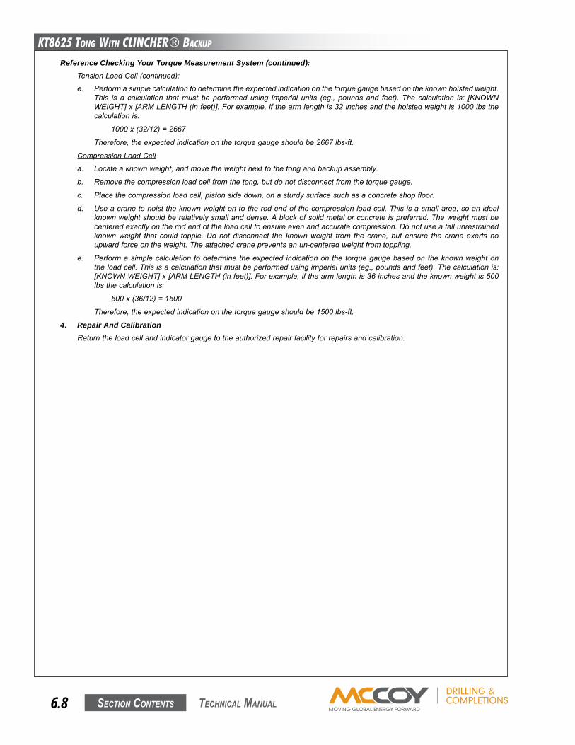
KT8625 Tong WiTh CLinChER® BaCKup
Section contentS6.8 technical Manual
Reference Checking Your Torque Measurement System (continued):TensionLoadCell(continued):
e. Performasimplecalculationtodeterminetheexpectedindicationonthetorquegaugebasedontheknownhoistedweight.This is a calculation thatmust be performedusing imperial units (eg., poundsand feet). The calculation is: [KNOWNWEIGHT]x[ARMLENGTH(infeet)].Forexample,ifthearmlengthis32inchesandthehoistedweightis1000lbsthecalculationis:
1000x(32/12)=2667
Therefore,theexpectedindicationonthetorquegaugeshouldbe2667lbs-ft.
CompressionLoadCell
a. Locateaknownweight,andmovetheweightnexttothetongandbackupassembly.
b. Removethecompressionloadcellfromthetong,butdonotdisconnectfromthetorquegauge.
c. Placethecompressionloadcell,pistonsidedown,onasturdysurfacesuchasaconcreteshopfloor.
d. Useacranetohoisttheknownweightontotherodendofthecompressionloadcell.Thisisasmallarea,soanidealknownweightshouldberelativelysmallanddense.Ablockofsolidmetalorconcreteispreferred.Theweightmustbecenteredexactlyontherodendoftheloadcelltoensureevenandaccuratecompression.Donotuseatallunrestrainedknownweight that could topple.Donot disconnect the knownweight from the crane, but ensure the craneexerts noupwardforceontheweight.Theattachedcranepreventsanun-centeredweightfromtoppling.
e. Performasimplecalculation todetermine theexpected indicationon the torquegaugebasedon theknownweightontheloadcell.Thisisacalculationthatmustbeperformedusingimperialunits(eg.,poundsandfeet).Thecalculationis:[KNOWNWEIGHT]x[ARMLENGTH(infeet)].Forexample,ifthearmlengthis36inchesandtheknownweightis500lbsthecalculationis:
500x(36/12)=1500
Therefore,theexpectedindicationonthetorquegaugeshouldbe1500lbs-ft.
4. Repair And CalibrationReturntheloadcellandindicatorgaugetotheauthorizedrepairfacilityforrepairsandcalibration.
KT8625 Tong WiTh CLinChER® BaCKup
Section contentS 7.1 technical Manual
hyDRaulic infoRMation
Section 7: Hydraulic Component InformationThemanufacturerinformationcontainedinthissectionhasbeenobtainedfrompubliclyavailablewebsitesandhasbeenprovidedforinformationpurposesonly.McCoyDrilling&Completionsdoesnotguaranteetheaccuracyoftheinformationcontainedinthissection.Alloriginalcopyrightsclaimedbythemanufacturer(s)apply.
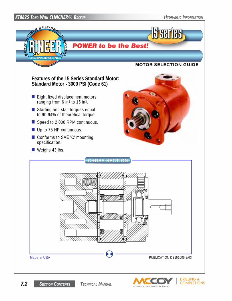
KT8625 Tong WiTh CLinChER® BaCKup
Section contentS7.2 technical Manual
hyDRaulic infoRMation
Eight fixed displacement motorsranging from 6 in3 to 15 in3.Starting and stall torques equalto 90-94% of theoretical torque.Speed to 2,000 RPM continuous.Up to 75 HP continuous.Conforms to SAE 'C' mountingspecification.Weighs 43 lbs.
Features of the 15 Series Standard Motor:Standard Motor - 3000 PSI (Code 61)
MOTOR SELECTION GUIDE
POWER to be the Best!
CROSS SECTION
Made in USA PUBLICATION DS151005 8/03
HYDRAULICS, INC.HYDRAULICS, INC.
R
MA
NU
FA
CT
URER OF HYDRAULIC
MO
TO
RS
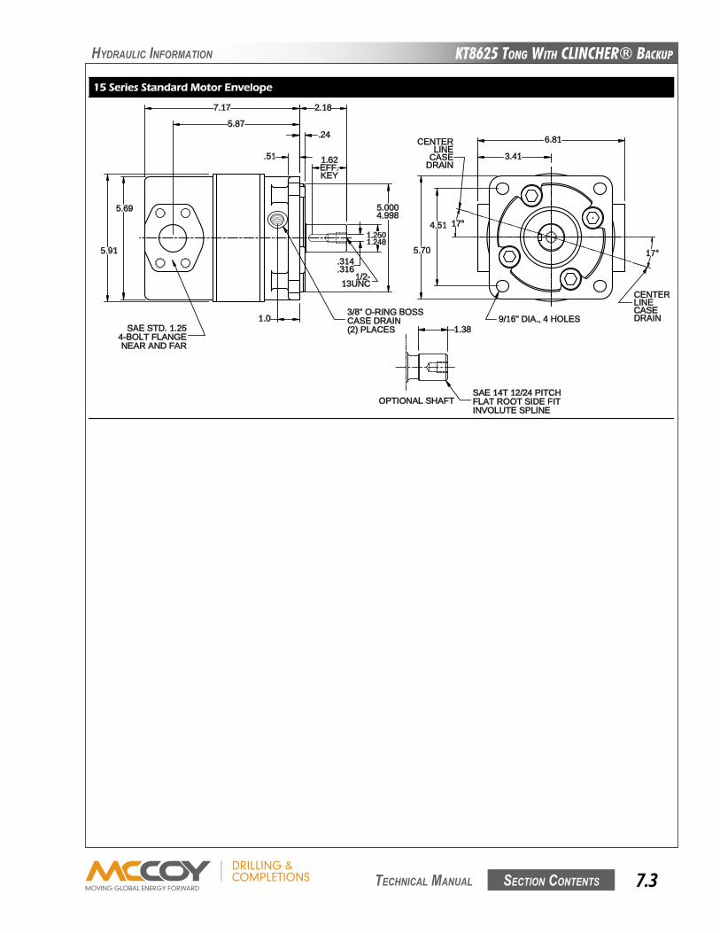
KT8625 Tong WiTh CLinChER® BaCKup
Section contentS 7.3 technical Manual
hyDRaulic infoRMation
1.38
SAE 14T 12/24 PITCHFLAT ROOT SIDE FITINVOLUTE SPLINE
OPTIONAL SHAFT
6.81
3.41
4.51
5.70
9/16" DIA., 4 HOLES
17°
17°
CENTERLINECASEDRAIN
CENTERLINE
CASEDRAIN
5.91
5.69
7.17 2.18
5.87.24
.51 1.62EFF.KEY
1.0
5.0004.998
1.2501.248
.314
.3161/2-
13UNC
3/8" O-RING BOSSCASE DRAIN(2) PLACESSAE STD. 1.25
4-BOLT FLANGENEAR AND FAR
15 Series Standard Motor Envelope
A
B
6.82
3.41
4.50SQR.
5.70
17°
CENTERLINECASEDRAIN
17°
CENTER LINECASE DRAIN
PORT"B"
PORT"A"
5.91
9.0 2.18
5.80.24
.50 1.62EFF.KEY
1.0
5.0004.998
1.2501.248
.313
.315
7.80
PORT 'A'
5.40
1.3
OPTIONAL SHAFT
1.8 2.2
REAR VIEW
SAE 14T 12/24 PITCHFLAT ROOT SIDE FITINVOLUTE SPLINE
ALTERNATEPORT "A"1-1/4 O-RING BOSS
ALTERNATEPORT "B"
1-1/4 O-RING BOSS
1/2-13UNCx 1/2 DP.
3/8" O-RING BOSSCASE DRAIN(2) PLACES
SAE STD. 1.254-BOLT FLANGENEAR AND FAR
SAE 1/4 O-RING BOSS
1/4 O-RING BOSS
9/16" DIA., 4 HOLES
15 Series Two Speed Envelope
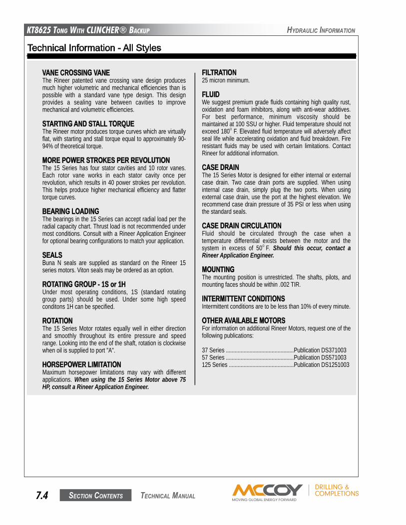
KT8625 Tong WiTh CLinChER® BaCKup
Section contentS7.4 technical Manual
hyDRaulic infoRMation
Technical Information - All Styles
VANE CROSSING VANEThe Rineer patented vane crossing vane design producesmuch higher volumetric and mechanical efficiencies than ispossible with a standard vane type design. This designprovides a sealing vane between cavities to improvemechanical and volumetric efficiencies.
STARTING AND STALL TORQUEThe Rineer motor produces torque curves which are virtuallyflat, with starting and stall torque equal to approximately 90-94% of theoretical torque.
MORE POWER STROKES PER REVOLUTIONThe 15 Series has four stator cavities and 10 rotor vanes.Each rotor vane works in each stator cavity once perrevolution, which results in 40 power strokes per revolution.This helps produce higher mechanical efficiency and flattertorque curves.
BEARING LOADINGThe bearings in the 15 Series can accept radial load per theradial capacity chart. Thrust load is not recommended undermost conditions. Consult with a Rineer Application Engineerfor optional bearing configurations to match your application.
SEALSBuna N seals are supplied as standard on the Rineer 15series motors. Viton seals may be ordered as an option.
ROTATING GROUP - 1S or 1HUnder most operating conditions, 1S (standard rotatinggroup parts) should be used. Under some high speedconditons 1H can be specified.
ROTATIONThe 15 Series Motor rotates equally well in either directionand smoothly throughout its entire pressure and speedrange. Looking into the end of the shaft, rotation is clockwisewhen oil is supplied to port "A".
HORSEPOWER LIMITATIONMaximum horsepower limitations may vary with differentapplications. When using the 15 Series Motor above 75HP, consult a Rineer Application Engineer.
FILTRATION25 micron minimum.
FLUIDWe suggest premium grade fluids containing high quality rust,oxidation and foam inhibitors, along with anti-wear additives.For best performance, minimum viscosity should bemaintained at 100 SSU or higher. Fluid temperature should notexceed 180O F. Elevated fluid temperature will adversely affectseal life while accelerating oxidation and fluid breakdown. Fireresistant fluids may be used with certain limitations. ContactRineer for additional information.
CASE DRAINThe 15 Series Motor is designed for either internal or externalcase drain. Two case drain ports are supplied. When usinginternal case drain, simply plug the two ports. When usingexternal case drain, use the port at the highest elevation. Werecommend case drain pressure of 35 PSI or less when usingthe standard seals.
CASE DRAIN CIRCULATIONFluid should be circulated through the case when atemperature differential exists between the motor and thesystem in excess of 50O F. Should this occur, contact aRineer Application Engineer.
MOUNTINGThe mounting position is unrestricted. The shafts, pilots, andmounting faces should be within .002 TIR.
INTERMITTENT CONDITIONSIntermittent conditions are to be less than 10% of every minute.
OTHER AVAILABLE MOTORSFor information on additional Rineer Motors, request one of thefollowing publications:
37 Series ..............................................Publication DS37100357 Series ..............................................Publication DS571003125 Series ............................................Publication DS1251003
Technical Information - Retractable Shaft Motor
RETRACTING THE SHAFTThe shaft is spring loaded into the engaged position. Pullingon the knob attached to the shaft at the rear of the motor willmove the shaft 1.25 inches into the motor.CAUTION: Retracting the shaft must be done when themotor and driven mechanism are not in operation andare unloaded.
RETAINING SHAFT IN RETRACTED POSITIONThe shaft is retained in the retracted position by inserting a2.0 inch wide spacer between the rear housing and the knobattached to the shaft. Depending on the application andmounting position of the motor, the spacer design may vary.Spacers are not supplied with the motor.
RE-ENGAGING THE SHAFTThis is accomplished by releasing the shaft, then rotating itclockwise until the splines of the shaft line up and engage thesplines of the driven mechanism.CAUTION: Re-engaging the shaft must be done when themotor and driven mechanism are not in operation and areunloaded.
BEARING LOADINGThe 15 series Retractable is not suitable for applications whichrequire radial or axial loading of the shaft.
MOUNTINGThe mounting position is unrestricted. CAUTION: The shaftextension and knob at the rear of the motor rotates whenthe motor is in operation.
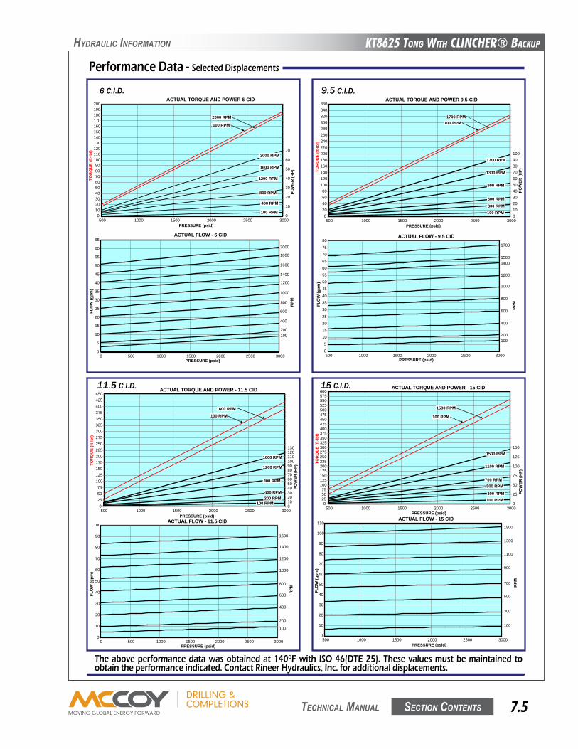
KT8625 Tong WiTh CLinChER® BaCKup
Section contentS 7.5 technical Manual
hyDRaulic infoRMation
Performance Data - Selected Displacements
The above performance data was obtained at 140OF with ISO 46(DTE 25). These values must be maintained to obtain the performance indicated. Contact Rineer Hydraulics, Inc. for additional displacements.
6 C.I.D.ACTUAL TORQUE AND POWER 6-CID
0102030405060708090
100110120130140150160170180190200
500 1000 1500 2000 2500 3000PRESSURE (psid)
TOR
QU
E(ft
-lbf)
0
10
20
30
40
50
60
70
POW
ER(H
P)
2000 RPM
100 RPM
2000 RPM
1200 RPM
400 RPM
100 RPM
800 RPM
1600 RPM
ACTUAL FLOW - 6 CID
0
5
10
15
20
25
30
35
40
45
50
55
60
65
0 500 1000 1500 2000 2500 3000PRESSURE (psid)
FLO
W(g
pm)
RPM800
1000
1200
1400
1600
1800
2000
200
400
600
100
9.5 C.I.D.
ACTUAL FLOW - 9.5 CID
0
5
10
15
20
25
30
35
40
45
50
55
60
65
70
75
80
500 1000 1500 2000 2500 3000PRESSURE (psid)
FLO
W(g
pm)
15001400
1200
1000
800
600
400
200100
1700
ACTUAL TORQUE AND POWER 9.5-CID
020406080
100120140160180200220240260280300320340360
500 1000 1500 2000 2500 3000PRESSURE (psid)
TOR
QU
E(ft
-lbf)
0102030405060708090100
POW
ER(H
P)
1700 RPM100 RPM
1700 RPM
900 RPM
300 RPM100 RPM
500 RPM
1300 RPM
RPM
11.5 C.I.D. ACTUAL TORQUE AND POWER - 11.5 CID
0255075
100125150175200225250275300325350375400425450
500 1000 1500 2000 2500 3000PRESSURE (psid)
TOR
QU
E(ft
-lbf)
0102030405060708090100110120130
POW
ER(H
P)
1600 RPM
800 RPM
200 RPM100 RPM
400 RPM
1200 RPM
1600 RPM100 RPM
ACTUAL FLOW - 11.5 CID
0
10
20
30
40
50
60
70
80
90
100
0 500 1000 1500 2000 2500 3000PRESSURE (psid)
FLO
W(g
pm)
1600
400
600
800
1000
1200
1400
100
200
RPM
15 C.I.D. ACTUAL TORQUE AND POWER - 15 CID
0255075
100125150175200225250275300325350375400425450475500525550575600
500 1000 1500 2000 2500 3000PRESSURE (psid)
TOR
QU
E(ft
-lbf)
0
25
50
75
100
125
150
POW
ER(H
P)
1500 RPM
100 RPM
1500 RPM
700 RPM
300 RPM100 RPM
500 RPM
1100 RPM
ACTUAL FLOW - 15 CID
0
10
20
30
40
50
60
70
80
90
100
110
500 1000 1500 2000 2500 3000PRESSURE (psid)
FLO
W(g
pm)
1500
1100
1300
500
700
900
100
300
RPM
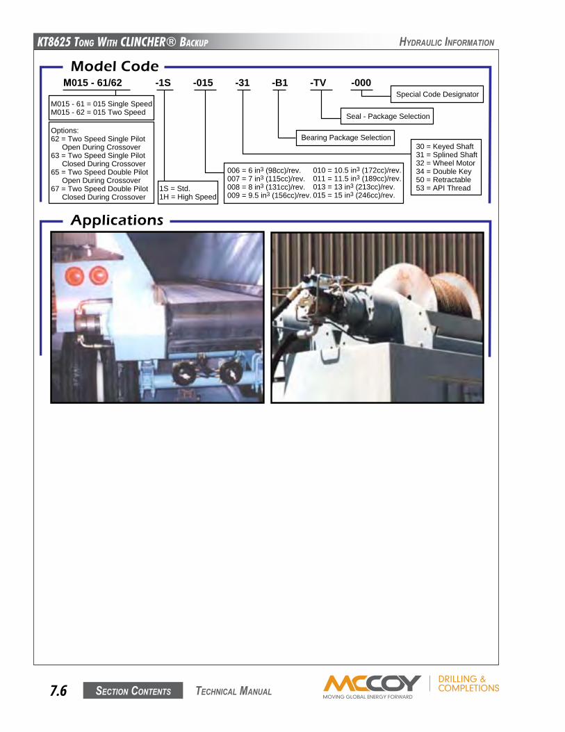
KT8625 Tong WiTh CLinChER® BaCKup
Section contentS7.6 technical Manual
hyDRaulic infoRMation
For durable hydraulic motors that meet your demands, specify Rineer.For over 35 years, we have specialized in only one thing - engineering the right motor for your needs.Rineer delivers the performance you can count on.
Model CodeM015 - 61/62 -1S -015 -31 -B1 -TV -000
M015 - 61 = 015 Single SpeedM015 - 62 = 015 Two Speed
Options:62 = Two Speed Single Pilot
Open During Crossover63 = Two Speed Single Pilot
Closed During Crossover65 = Two Speed Double Pilot
Open During Crossover67 = Two Speed Double Pilot
Closed During Crossover1S = Std.1H = High Speed
006 = 6 in3 (98cc)/rev.007 = 7 in3 (115cc)/rev.008 = 8 in3 (131cc)/rev.009 = 9.5 in3 (156cc)/rev.
010 = 10.5 in3 (172cc)/rev.011 = 11.5 in3 (189cc)/rev.013 = 13 in3 (213cc)/rev.015 = 15 in3 (246cc)/rev.
30 = Keyed Shaft31 = Splined Shaft32 = Wheel Motor34 = Double Key50 = Retractable53 = API Thread
Bearing Package Selection
Seal - Package Selection
Special Code Designator
331 Breesport San Antonio, Texas 78216
210-341-6333 Fax: 210-341-1231 e-mail: [email protected]
Applications
Rineer Hydraulics, Inc. warrants that, at the time of shipment toPurchaser, our product will be free of defects in the material andworkmanship. The above warranty is LIMITED to defectiveproducts returned by Purchaser to Rineer Hydraulics, Inc., freightprepaid within four hundred and fifty-five (455) days from date ofshipment, or one (1) year from date of first use, whichever expiresfirst. We will repair or replace any product or part thereof which isproved to be defective in workmanship or material. There is noother warranty, expressed or implied, and in no event shall RineerHydraulics, Inc. be liable for consequential or special damages.Dismantling the product, operation of the product beyond thepublished capabilities or for purposes other than that for which theproduct was designed, shall void this warranty.
Limited Warranty Policy
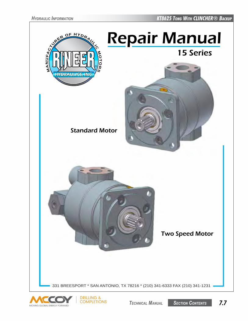
KT8625 Tong WiTh CLinChER® BaCKup
Section contentS 7.7 technical Manual
hyDRaulic infoRMation
Standard Motor
Two Speed Motor
HYDRAULICS, INC.HYDRAULICS, INC.
R
MA
NU
FA
CT
U
RER OF HYDRAU
LIC
MO
TO
RS
15 Series
Repair Manual
331 BREESPORT * SAN ANTONIO, TX 78216 * (210) 341-6333 FAX (210) 341-1231
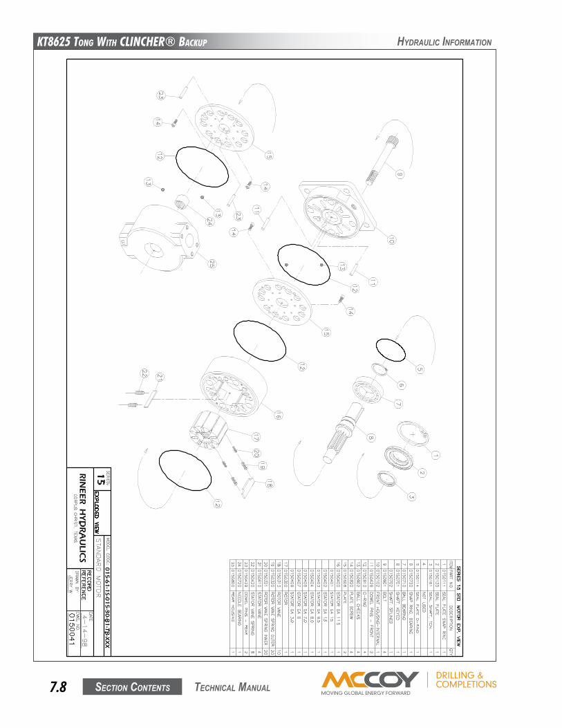
KT8625 Tong WiTh CLinChER® BaCKup
Section contentS7.8 technical Manual
hyDRaulic infoRMation
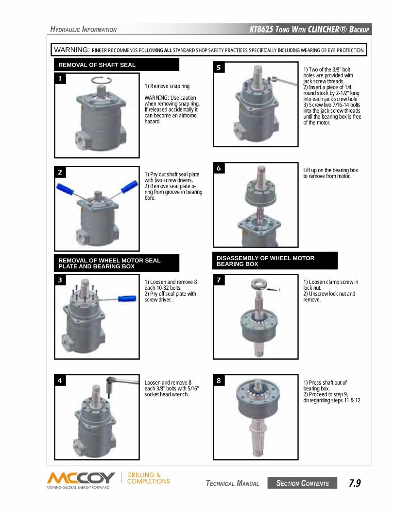
KT8625 Tong WiTh CLinChER® BaCKup
Section contentS 7.9 technical Manual
hyDRaulic infoRMation
WARNING: RINEER RECOMMENDS FOLLOWING ALL STANDARD SHOP SAFETY PRACTICES SPECIFICALLY INCLUDING WEARING OF EYE PROTECTION.
1
2
3
4
5
6
7
8
5
1) Remove snap ring
WARNING: Use caution when removing snap ring. If released accidentally it can become an airborne hazard.
1) Pry out shaft seal plate with two screw drivers.2) Remove seal plate o-ring from groove in bearing bore.
1) Loosen and remove 8 each 10-32 bolts.2) Pry off seal plate with screw driver.
Loosen and remove 8 each 3/8" bolts with 5/16" socket head wrench.
1) Press shaft out of bearing box.2) Proceed to step 9, disregarding steps 11 & 12
1) Loosen clamp screw in lock nut.2) Unscrew lock nut and remove.
Lift up on the bearing box to remove from motor.
1) Two of the 3/8" bolt holes are provided with jack screw threads.2) Insert a piece of 1/4" round stock by 2-1/2" long into each jack screw hole3) Screw two 7/16-14 bolts into the jack screw threads until the bearing box is free of the motor.
REMOVAL OF SHAFT SEAL
REMOVAL OF WHEEL MOTOR SEALPLATE AND BEARING BOX
DISASSEMBLY OF WHEEL MOTORBEARING BOX
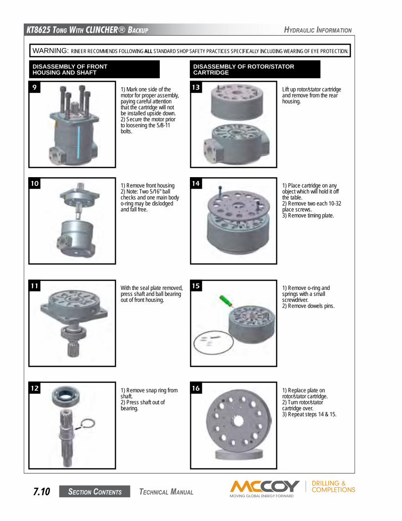
KT8625 Tong WiTh CLinChER® BaCKup
Section contentS7.10 technical Manual
hyDRaulic infoRMation
WARNING: RINEER RECOMMENDS FOLLOWING ALL STANDARD SHOP SAFETY PRACTICES SPECIFICALLY INCLUDING WEARING OF EYE PROTECTION.
9
10
11
12
13
14
15
16
6
1) Remove front housing2) Note: Two 5/16" ball checks and one main body o-ring may be dislodged and fall free.
1) Mark one side of the motor for proper assembly, paying careful attention that the cartridge will not be installed upside down.2) Secure the motor prior to loosening the 5/8-11 bolts.
With the seal plate removed, press shaft and ball bearing out of front housing.
1) Remove snap ring from shaft.2) Press shaft out of bearing.
1) Replace plate on rotor/stator cartridge.2) Turn rotor/stator cartridge over.3) Repeat steps 14 & 15.
1) Remove o-ring and springs with a small screwdriver.2) Remove dowels pins.
1) Place cartridge on any object which will hold it off the table.2) Remove two each 10-32 place screws.3) Remove timing plate.
Lift up rotor/stator cartridge and remove from the rear housing.
DISASSEMBLY OF FRONTHOUSING AND SHAFT
DISASSEMBLY OF ROTOR/STATORCARTRIDGE
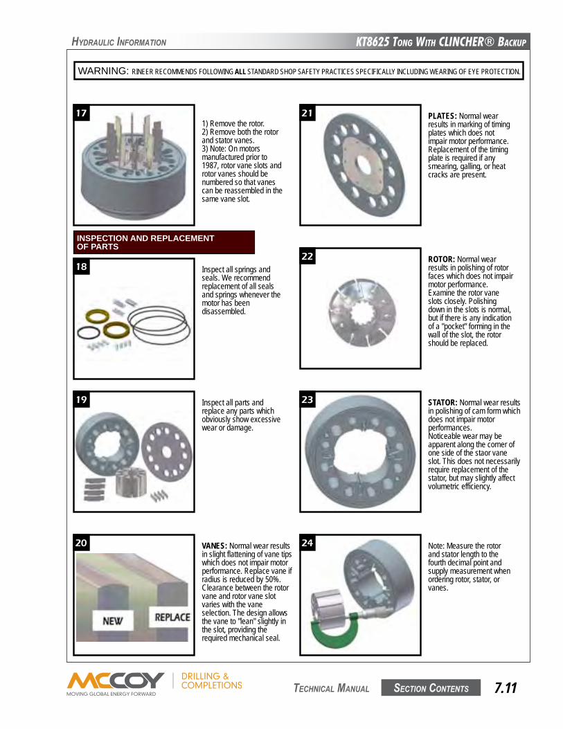
KT8625 Tong WiTh CLinChER® BaCKup
Section contentS 7.11 technical Manual
hyDRaulic infoRMation
WARNING: RINEER RECOMMENDS FOLLOWING ALL STANDARD SHOP SAFETY PRACTICES SPECIFICALLY INCLUDING WEARING OF EYE PROTECTION.
17 21
22
23
24
18
19
20
7
1) Remove the rotor.2) Remove both the rotor and stator vanes.3) Note: On motors manufactured prior to 1987, rotor vane slots and rotor vanes should be numbered so that vanes can be reassembled in the same vane slot.
Inspect all springs and seals. We recommend replacement of all seals and springs whenever the motor has been disassembled.
Inspect all parts and replace any parts which obviously show excessive wear or damage.
VANES: Normal wear results in slight flattening of vane tips which does not impair motor performance. Replace vane if radius is reduced by 50%.Clearance between the rotor vane and rotor vane slot varies with the vane selection. The design allows the vane to "lean" slightly in the slot, providing the required mechanical seal.
Note: Measure the rotor and stator length to the fourth decimal point and supply measurement when ordering rotor, stator, or vanes.
STATOR: Normal wear results in polishing of cam form which does not impair motor performances.Noticeable wear may be apparent along the corner of one side of the staor vane slot. This does not necessarily require replacement of the stator, but may slightly affect volumetric efficiency.
ROTOR: Normal wear results in polishing of rotor faces which does not impair motor performance.Examine the rotor vane slots closely. Polishing down in the slots is normal, but if there is any indication of a "pocket" forming in the wall of the slot, the rotor should be replaced.
PLATES: Normal wear results in marking of timing plates which does not impair motor performance.Replacement of the timing plate is required if any smearing, galling, or heat cracks are present.
INSPECTION AND REPLACEMENTOF PARTS
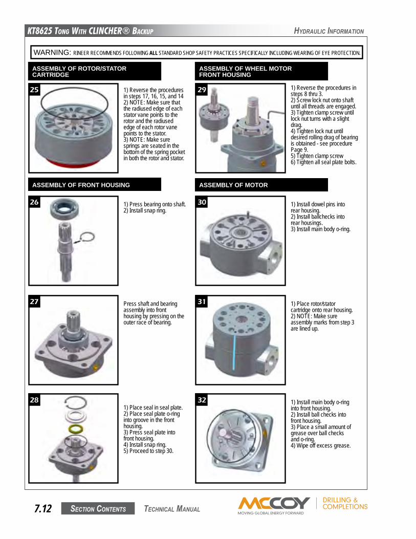
KT8625 Tong WiTh CLinChER® BaCKup
Section contentS7.12 technical Manual
hyDRaulic infoRMation
WARNING: RINEER RECOMMENDS FOLLOWING ALL STANDARD SHOP SAFETY PRACTICES SPECIFICALLY INCLUDING WEARING OF EYE PROTECTION.
25
26
27
28
29
30
31
32
8
1) Reverse the procedures in steps 17, 16, 15, and 142) NOTE: Make sure that the radiused edge of each stator vane points to the rotor and the radiused edge of each rotor vane points to the stator.3) NOTE: Make sure springs are seated in the bottom of the spring pocket in both the rotor and stator.
1) Press bearing onto shaft.2) Install snap ring.
Press shaft and bearing assembly into front housing by pressing on the outer race of bearing.
1) Place seal in seal plate.2) Place seal plate o-ring into groove in the front housing.3) Press seal plate into front housing.4) Install snap ring.5) Proceed to step 30.
1) Install main body o-ring into front housing.2) Install ball checks into front housing.3) Place a small amount of grease over ball checks and o-ring.4) Wipe off excess grease.
1) Place rotor/stator cartridge onto rear housing.2) NOTE: Make sure assembly marks from step 3 are lined up.
1) Install dowel pins into rear housing.2) Install ballchecks into rear housings.3) Install main body o-ring.
1) Reverse the procedures in steps 8 thru 3.2) Screw lock nut onto shaft until all threads are engaged.3) Tighten clamp screw until lock nut turns with a slight drag.4) Tighten lock nut until desired rolling drag of bearing is obtained - see procedure Page 9.5) Tighten clamp screw6) Tighten all seal plate bolts.
ASSEMBLY OF ROTOR/STATORCARTRIDGE
ASSEMBLY OF FRONT HOUSING
ASSEMBLY OF WHEEL MOTORFRONT HOUSING
ASSEMBLY OF MOTOR
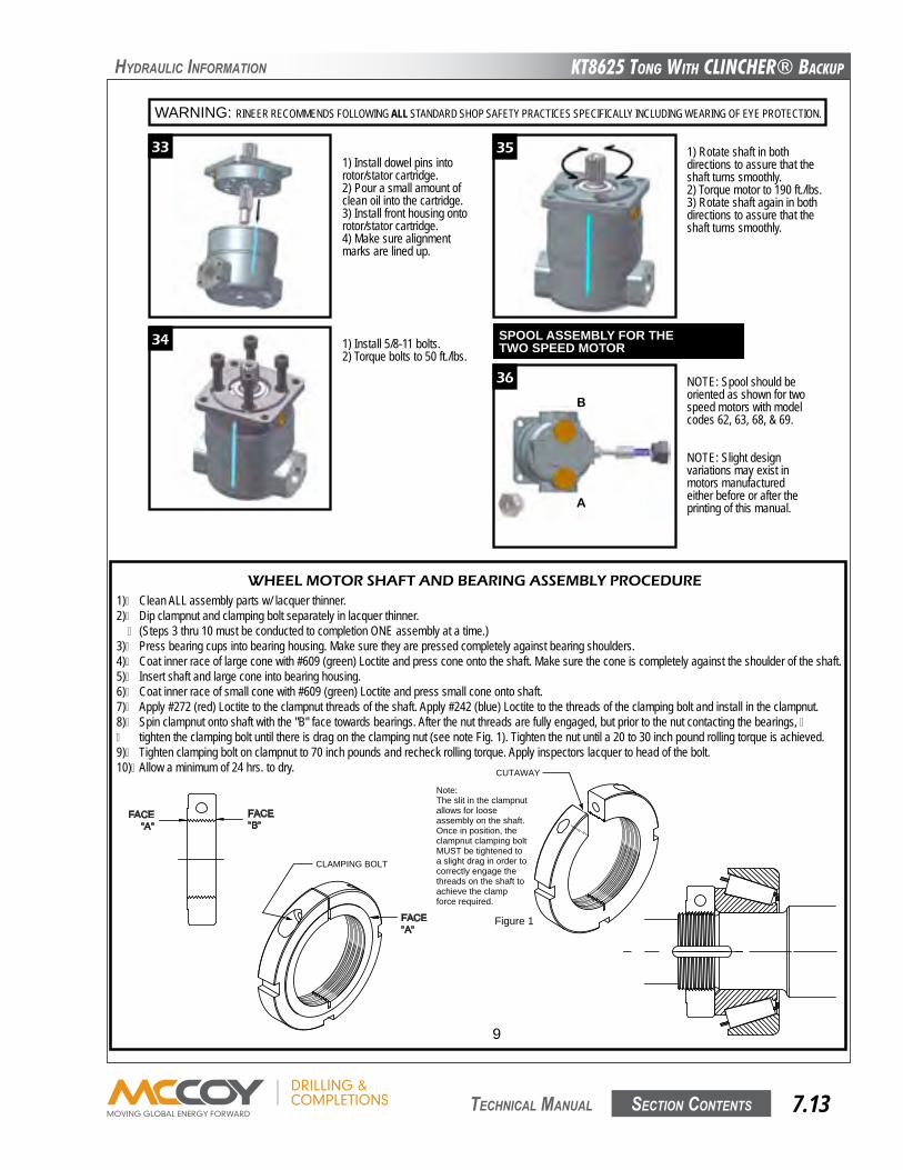
KT8625 Tong WiTh CLinChER® BaCKup
Section contentS 7.13 technical Manual
hyDRaulic infoRMation
WARNING: RINEER RECOMMENDS FOLLOWING ALL STANDARD SHOP SAFETY PRACTICES SPECIFICALLY INCLUDING WEARING OF EYE PROTECTION.
33
34
35
36
B
A
9
1) Install dowel pins into rotor/stator cartridge.2) Pour a small amount of clean oil into the cartridge.3) Install front housing onto rotor/stator cartridge.4) Make sure alignment marks are lined up.
1) Install 5/8-11 bolts.2) Torque bolts to 50 ft./lbs.
1) Rotate shaft in both directions to assure that the shaft turns smoothly.2) Torque motor to 190 ft./lbs.3) Rotate shaft again in both directions to assure that the shaft turns smoothly.
NOTE: Spool should be oriented as shown for two speed motors with model codes 62, 63, 68, & 69.
NOTE: Slight design variations may exist in motors manufactured either before or after the printing of this manual.
SPOOL ASSEMBLY FOR THETWO SPEED MOTOR
1)� Clean ALL assembly parts w/ lacquer thinner.2)� Dip clampnut and clamping bolt separately in lacquer thinner. � (Steps 3 thru 10 must be conducted to completion ONE assembly at a time.)3)� Press bearing cups into bearing housing. Make sure they are pressed completely against bearing shoulders.4)� Coat inner race of large cone with #609 (green) Loctite and press cone onto the shaft. Make sure the cone is completely against the shoulder of the shaft.5)� Insert shaft and large cone into bearing housing.6)� Coat inner race of small cone with #609 (green) Loctite and press small cone onto shaft.7)� Apply #272 (red) Loctite to the clampnut threads of the shaft. Apply #242 (blue) Loctite to the threads of the clamping bolt and install in the clampnut.8)� Spin clampnut onto shaft with the "B" face towards bearings. After the nut threads are fully engaged, but prior to the nut contacting the bearings, �� tighten the clamping bolt until there is drag on the clamping nut (see note Fig. 1). Tighten the nut until a 20 to 30 inch pound rolling torque is achieved.9)� Tighten clamping bolt on clampnut to 70 inch pounds and recheck rolling torque. Apply inspectors lacquer to head of the bolt.10)� Allow a minimum of 24 hrs. to dry.
Figure 1
CUTAWAY
Note:The slit in the clampnut allows for loose assembly on the shaft. Once in position, the clampnut clamping bolt MUST be tightened to a slight drag in order to correctly engage the threads on the shaft to achieve the clamp force required.
FACE"A"
CLAMPING BOLT
FACE"A"
FACE"B"
WHEEL MOTOR SHAFT AND BEARING ASSEMBLY PROCEDURE
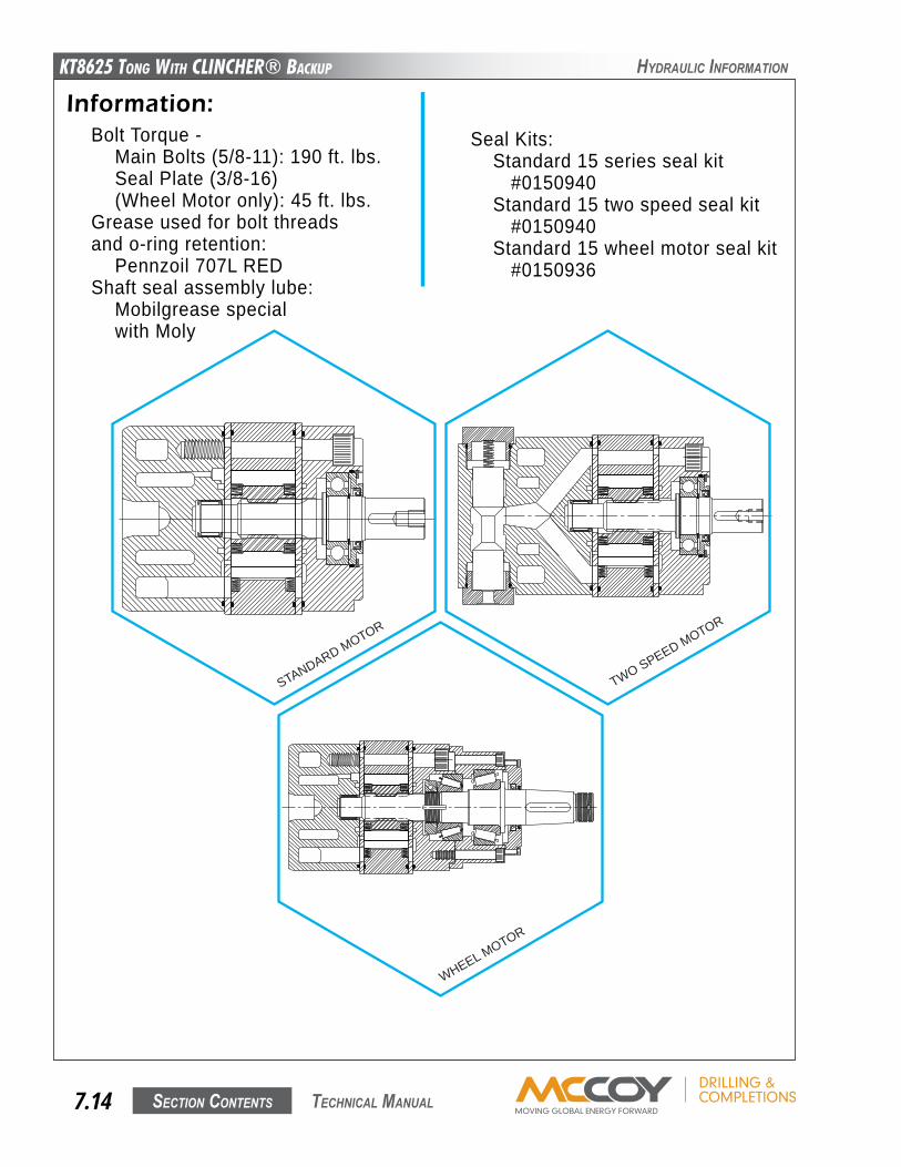
KT8625 Tong WiTh CLinChER® BaCKup
Section contentS7.14 technical Manual
hyDRaulic infoRMation
Information:Bolt Torque -� Main Bolts (5/8-11): 190 ft. lbs.� Seal Plate (3/8-16)� (Wheel Motor only): 45 ft. lbs.Grease used for bolt threadsand o-ring retention:� Pennzoil 707L REDShaft seal assembly lube:� Mobilgrease special� with Moly
Seal Kits:� Standard 15 series seal kit� � #0150940� Standard 15 two speed seal kit� � #0150940� Standard 15 wheel motor seal kit� � #0150936
331 Breesport San Antonio, Texas 78216
210-341-6333 Fax: 210-341-1231 e-mail: [email protected]
WHEEL MOTOR
STANDARD MOTOR
TWO SPEED MOTOR
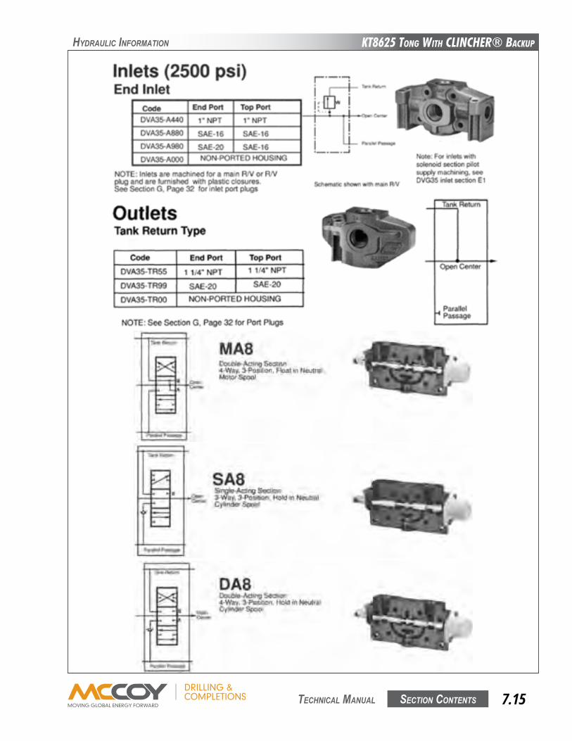
KT8625 Tong WiTh CLinChER® BaCKup
Section contentS 7.15 technical Manual
hyDRaulic infoRMation
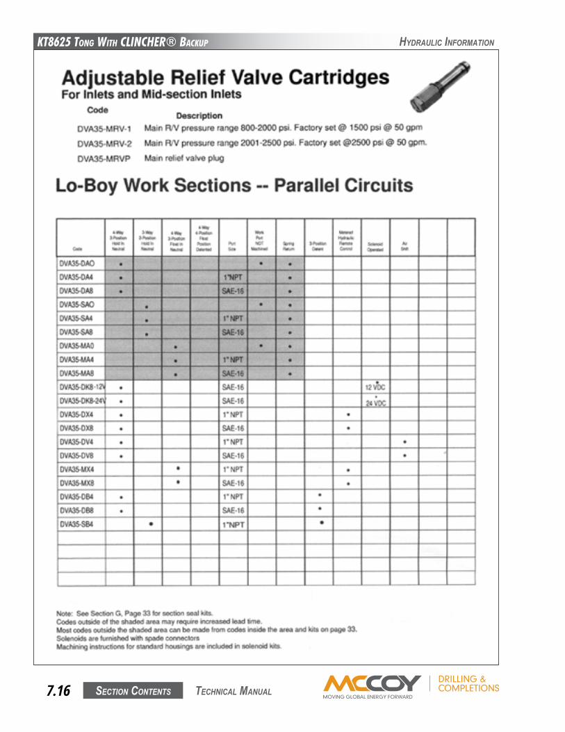
KT8625 Tong WiTh CLinChER® BaCKup
Section contentS7.16 technical Manual
hyDRaulic infoRMation
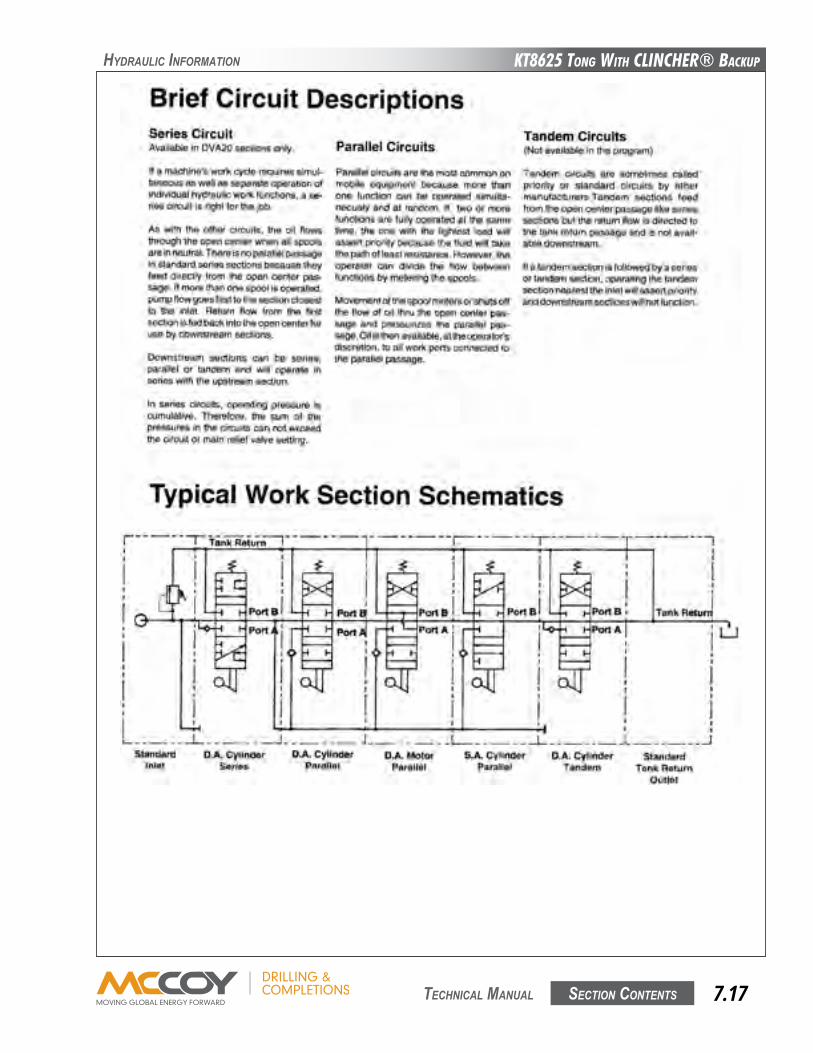
KT8625 Tong WiTh CLinChER® BaCKup
Section contentS 7.17 technical Manual
hyDRaulic infoRMation
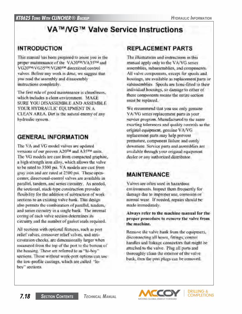
KT8625 Tong WiTh CLinChER® BaCKup
Section contentS7.18 technical Manual
hyDRaulic infoRMation
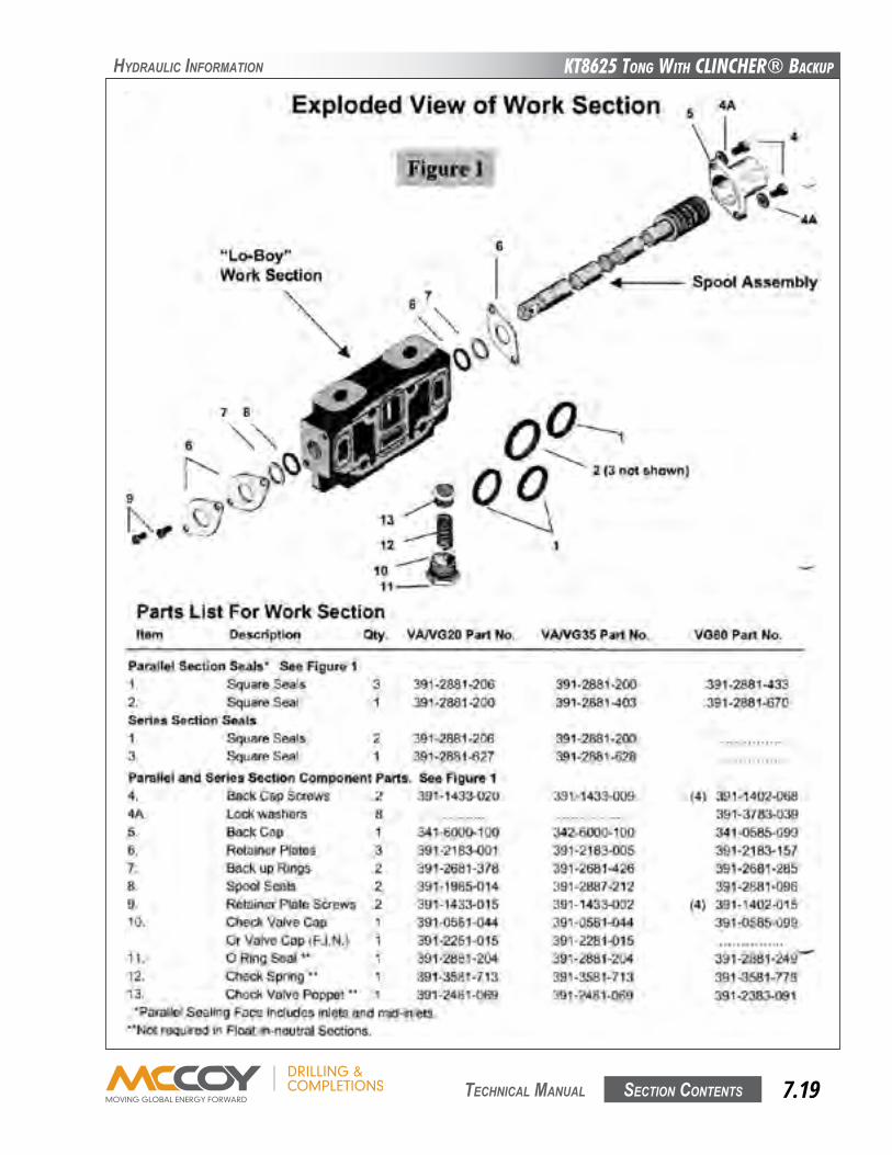
KT8625 Tong WiTh CLinChER® BaCKup
Section contentS 7.19 technical Manual
hyDRaulic infoRMation
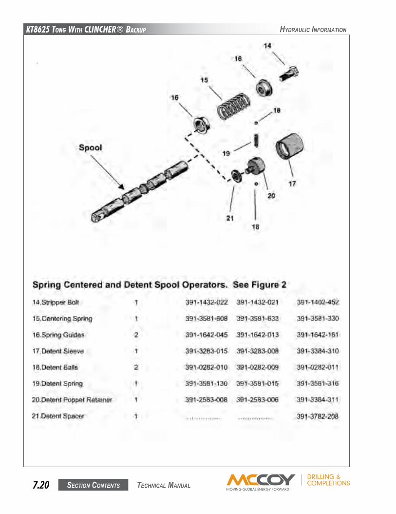
KT8625 Tong WiTh CLinChER® BaCKup
Section contentS7.20 technical Manual
hyDRaulic infoRMation
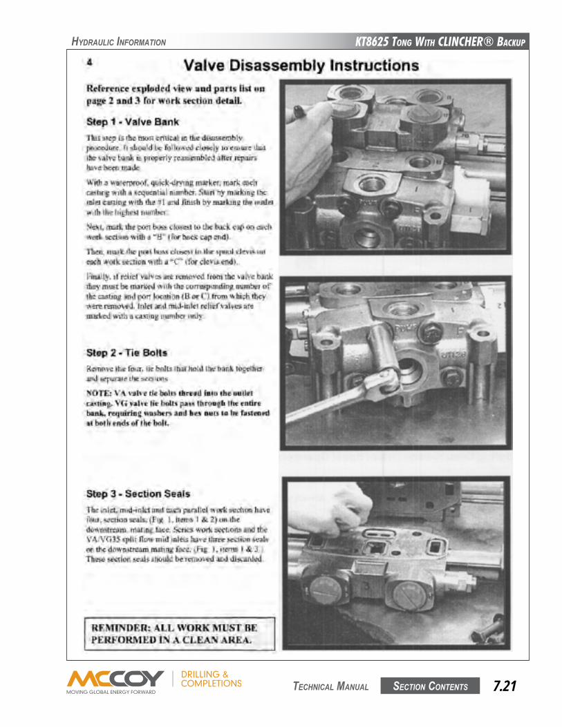
KT8625 Tong WiTh CLinChER® BaCKup
Section contentS 7.21 technical Manual
hyDRaulic infoRMation
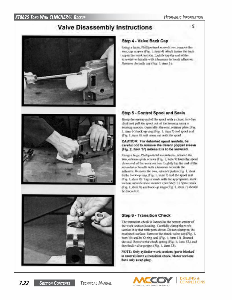
KT8625 Tong WiTh CLinChER® BaCKup
Section contentS7.22 technical Manual
hyDRaulic infoRMation
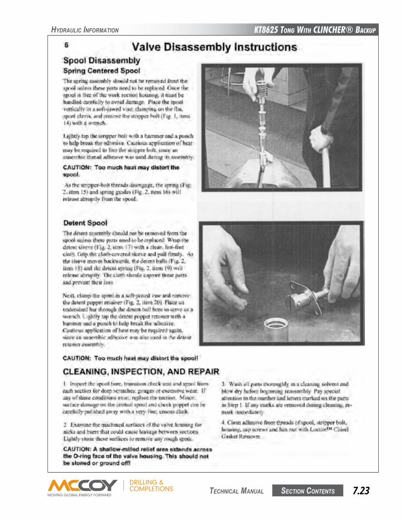
KT8625 Tong WiTh CLinChER® BaCKup
Section contentS 7.23 technical Manual
hyDRaulic infoRMation
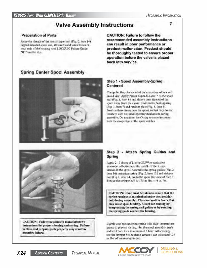
KT8625 Tong WiTh CLinChER® BaCKup
Section contentS7.24 technical Manual
hyDRaulic infoRMation
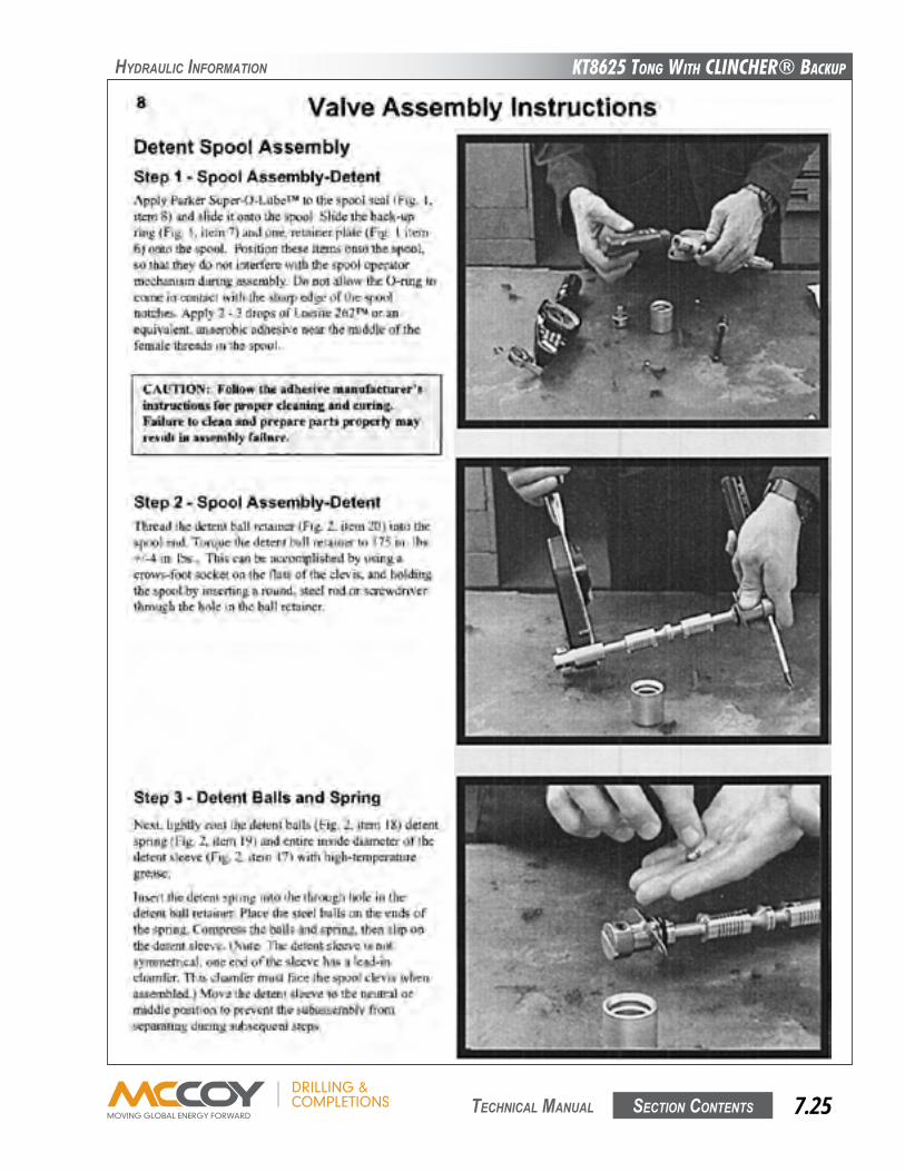
KT8625 Tong WiTh CLinChER® BaCKup
Section contentS 7.25 technical Manual
hyDRaulic infoRMation
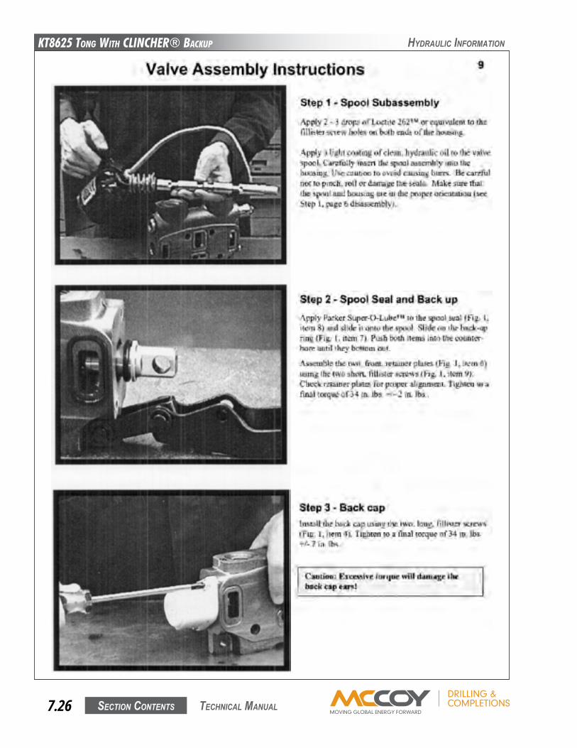
KT8625 Tong WiTh CLinChER® BaCKup
Section contentS7.26 technical Manual
hyDRaulic infoRMation
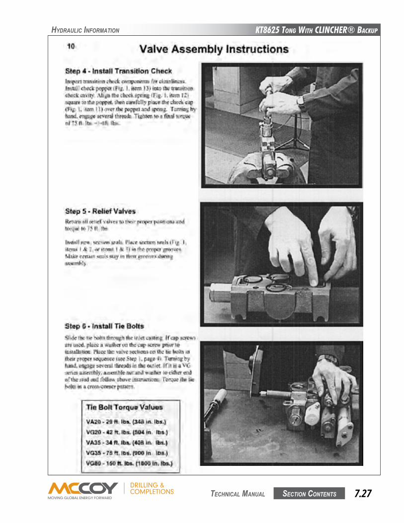
KT8625 Tong WiTh CLinChER® BaCKup
Section contentS 7.27 technical Manual
hyDRaulic infoRMation
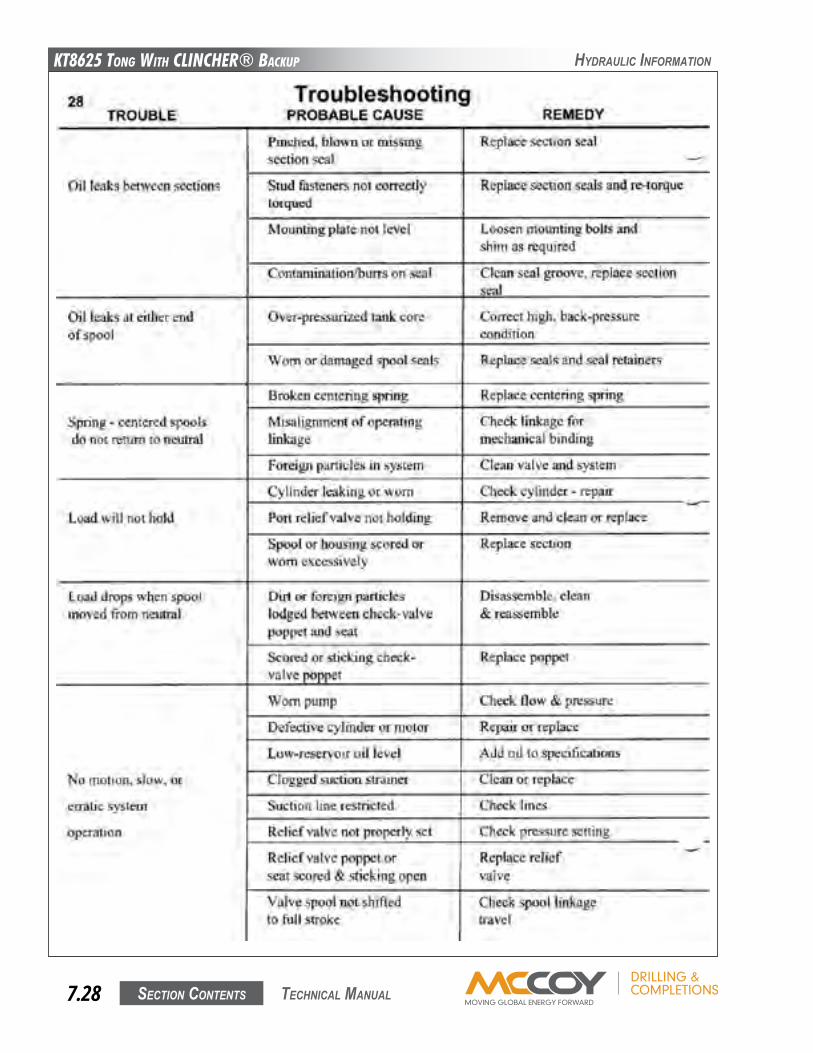
KT8625 Tong WiTh CLinChER® BaCKup
Section contentS7.28 technical Manual
hyDRaulic infoRMation
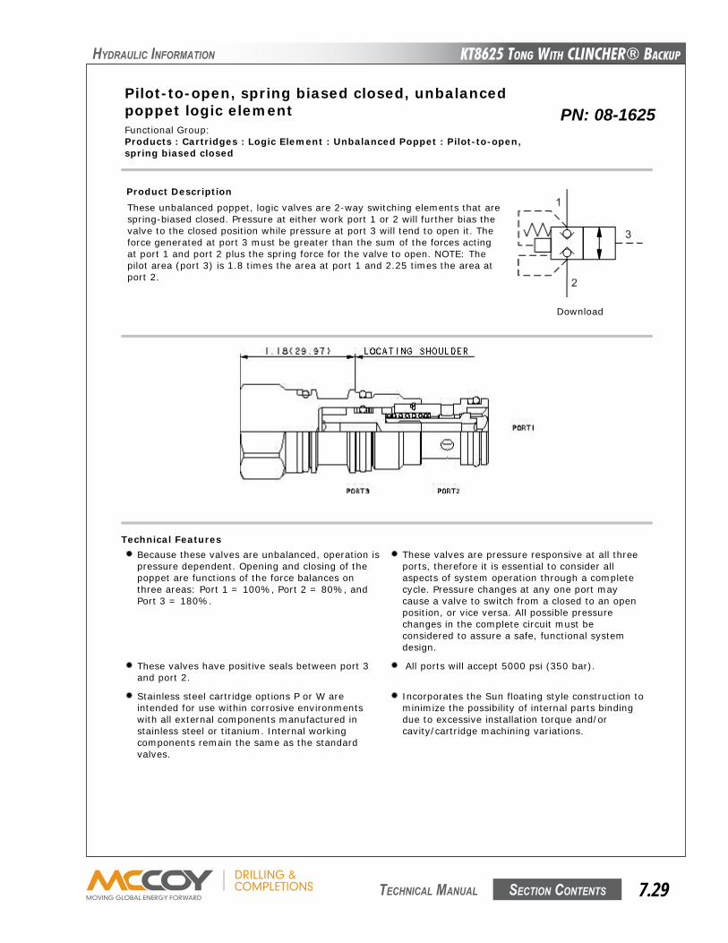
KT8625 Tong WiTh CLinChER® BaCKup
Section contentS 7.29 technical Manual
hyDRaulic infoRMation
Pilot-to-open, spring biased closed, unbalancedpoppet logic element
Capacity:15 gpm (60
L/min.)
Functional Group:Products : Cartridges : Logic Element : Unbalanced Poppet : Pilot-to-open,spring biased closed
Model:LKDC-XDN
Product DescriptionThese unbalanced poppet, logic valves are 2-way switching elements that arespring-biased closed. Pressure at either work port 1 or 2 will further bias thevalve to the closed position while pressure at port 3 will tend to open it. Theforce generated at port 3 must be greater than the sum of the forces actingat port 1 and port 2 plus the spring force for the valve to open. NOTE: Thepilot area (port 3) is 1.8 times the area at port 1 and 2.25 times the area atport 2.
Download
Technical FeaturesBecause these valves are unbalanced, operation ispressure dependent. Opening and closing of thepoppet are functions of the force balances onthree areas: Port 1 = 100%, Port 2 = 80%, andPort 3 = 180%.
These valves are pressure responsive at all threeports, therefore it is essential to consider allaspects of system operation through a completecycle. Pressure changes at any one port maycause a valve to switch from a closed to an openposition, or vice versa. All possible pressurechanges in the complete circuit must beconsidered to assure a safe, functional systemdesign.
These valves have positive seals between port 3and port 2.
All ports will accept 5000 psi (350 bar).
Stainless steel cartridge options P or W areintended for use within corrosive environmentswith all external components manufactured instainless steel or titanium. Internal workingcomponents remain the same as the standardvalves.
Incorporates the Sun floating style construction tominimize the possibility of internal parts bindingdue to excessive installation torque and/orcavity/cartridge machining variations.
Technical DataU.S. Units Metric Units
Model Weight 0.28 lb. 0.13 kg.Cavity T-11ACapacity 15 gpm 60 L/min.
PN: 08-1625
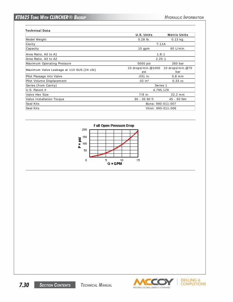
KT8625 Tong WiTh CLinChER® BaCKup
Section contentS7.30 technical Manual
hyDRaulic infoRMation
Area Ratio, A3 to A1 1.8:1Area Ratio, A3 to A2 2.25:1Maximum Operating Pressure 5000 psi 350 bar
Maximum Valve Leakage at 110 SUS (24 cSt) 10 drops/min.@1000psi
10 drops/min.@70bar
Pilot Passage into Valve .031 in. 0,8 mmPilot Volume Displacement .02 in³ 0,33 ccSeries (from Cavity) Series 1U.S. Patent # 4,795,129Valve Hex Size 7/8 in. 22,2 mmValve Installation Torque 30 - 35 lbf ft 45 - 50 NmSeal Kits Buna: 990-011-007Seal Kits Viton: 990-011-006
LKDC-XDN
Control Minimum Pilot Pressure External Material/SealMaterial
X Not Adjustable +0.00 D 50 psi (3,5 bar) +0.00 N Buna-N +0.00
If the material/seal is P, the control must be XIf the material/seal is W, the control must be X
Explanation of Sun cartridge control options - US units.Explanation of Sun cartridge control options - metric units.
Copyright © 2007-2008 Sun Hydraulics Corporation. All rights reserved.Terms and Conditions - ISO Certification - Statement of Privacy
Pilot-to-open, spring biased closed, unbalancedpoppet logic element
Capacity:15 gpm (60
L/min.)
Functional Group:Products : Cartridges : Logic Element : Unbalanced Poppet : Pilot-to-open,spring biased closed
Model:LKDC-XDN
Product DescriptionThese unbalanced poppet, logic valves are 2-way switching elements that arespring-biased closed. Pressure at either work port 1 or 2 will further bias thevalve to the closed position while pressure at port 3 will tend to open it. Theforce generated at port 3 must be greater than the sum of the forces actingat port 1 and port 2 plus the spring force for the valve to open. NOTE: Thepilot area (port 3) is 1.8 times the area at port 1 and 2.25 times the area atport 2.
Download
Technical FeaturesBecause these valves are unbalanced, operation ispressure dependent. Opening and closing of thepoppet are functions of the force balances onthree areas: Port 1 = 100%, Port 2 = 80%, andPort 3 = 180%.
These valves are pressure responsive at all threeports, therefore it is essential to consider allaspects of system operation through a completecycle. Pressure changes at any one port maycause a valve to switch from a closed to an openposition, or vice versa. All possible pressurechanges in the complete circuit must beconsidered to assure a safe, functional systemdesign.
These valves have positive seals between port 3and port 2.
All ports will accept 5000 psi (350 bar).
Stainless steel cartridge options P or W areintended for use within corrosive environmentswith all external components manufactured instainless steel or titanium. Internal workingcomponents remain the same as the standardvalves.
Incorporates the Sun floating style construction tominimize the possibility of internal parts bindingdue to excessive installation torque and/orcavity/cartridge machining variations.
Technical DataU.S. Units Metric Units
Model Weight 0.28 lb. 0.13 kg.Cavity T-11ACapacity 15 gpm 60 L/min.
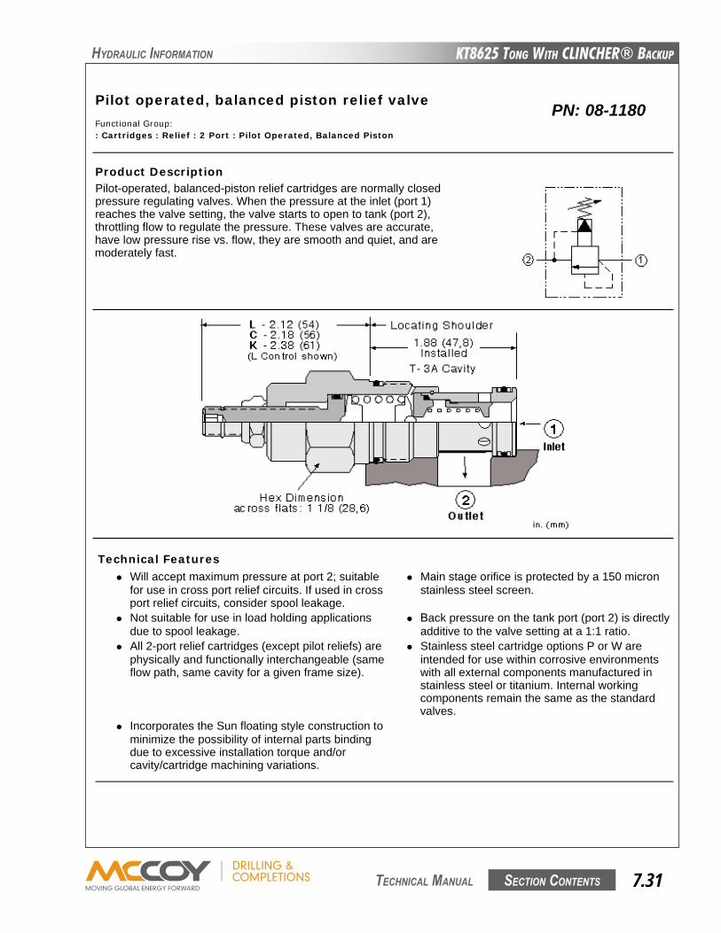
KT8625 Tong WiTh CLinChER® BaCKup
Section contentS 7.31 technical Manual
hyDRaulic infoRMation
Pilot operated, balanced piston relief valveCapacity:
50 gpm (200 L/min.)
Functional Group:: Cartridges : Relief : 2 Port : Pilot Operated, Balanced Piston
Model:
RPGC
Product DescriptionPilot-operated, balanced-piston relief cartridges are normally closedpressure regulating valves. When the pressure at the inlet (port 1)reaches the valve setting, the valve starts to open to tank (port 2),throttling flow to regulate the pressure. These valves are accurate,have low pressure rise vs. flow, they are smooth and quiet, and aremoderately fast.
Technical Features Will accept maximum pressure at port 2; suitable
for use in cross port relief circuits. If used in crossport relief circuits, consider spool leakage.
Main stage orifice is protected by a 150 micronstainless steel screen.
Not suitable for use in load holding applicationsdue to spool leakage.
Back pressure on the tank port (port 2) is directlyadditive to the valve setting at a 1:1 ratio.
All 2-port relief cartridges (except pilot reliefs) arephysically and functionally interchangeable (sameflow path, same cavity for a given frame size).
Stainless steel cartridge options P or W areintended for use within corrosive environmentswith all external components manufactured instainless steel or titanium. Internal workingcomponents remain the same as the standardvalves.
Incorporates the Sun floating style construction tominimize the possibility of internal parts bindingdue to excessive installation torque and/orcavity/cartridge machining variations.
PN: 08-1180
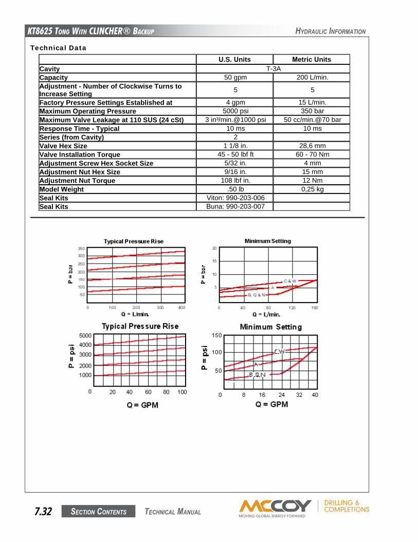
KT8625 Tong WiTh CLinChER® BaCKup
Section contentS7.32 technical Manual
hyDRaulic infoRMation
Technical DataU.S. Units Metric Units
Cavity T-3ACapacity 50 gpm 200 L/min.Adjustment - Number of Clockwise Turns toIncrease Setting 5 5
Factory Pressure Settings Established at 4 gpm 15 L/min.Maximum Operating Pressure 5000 psi 350 barMaximum Valve Leakage at 110 SUS (24 cSt) 3 in³/min.@1000 psi 50 cc/min.@70 barResponse Time - Typical 10 ms 10 msSeries (from Cavity) 2Valve Hex Size 1 1/8 in. 28,6 mmValve Installation Torque 45 - 50 lbf ft 60 - 70 NmAdjustment Screw Hex Socket Size 5/32 in. 4 mmAdjustment Nut Hex Size 9/16 in. 15 mmAdjustment Nut Torque 108 lbf in. 12 NmModel Weight .50 lb 0,25 kgSeal Kits Viton: 990-203-006Seal Kits Buna: 990-203-007
Option Selection
RPGC-L A N
Preferred Options
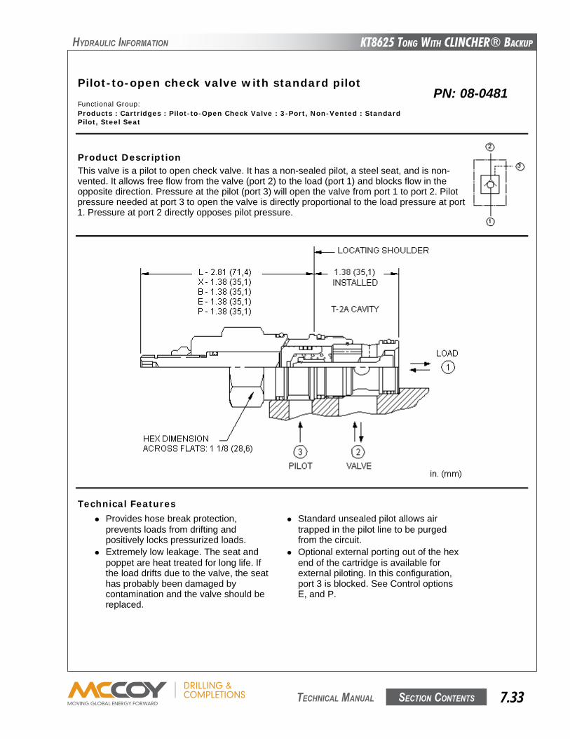
KT8625 Tong WiTh CLinChER® BaCKup
Section contentS 7.33 technical Manual
hyDRaulic infoRMation
Pilot-to-open check valve with standard pilotCapacity:
30gpm (120 L/min.)
Functional Group:Products : Cartridges : Pilot-to-Open Check Valve : 3-Port, Non-Vented : StandardPilot, Steel Seat
Model:
CKEB
Product DescriptionThis valve is a pilot to open check valve. It has a non-sealed pilot, a steel seat, and is non-vented. It allows free flow from the valve (port 2) to the load (port 1) and blocks flow in theopposite direction. Pressure at the pilot (port 3) will open the valve from port 1 to port 2. Pilotpressure needed at port 3 to open the valve is directly proportional to the load pressure at port1. Pressure at port 2 directly opposes pilot pressure.
Technical Features Provides hose break protection,
prevents loads from drifting andpositively locks pressurized loads.
Standard unsealed pilot allows airtrapped in the pilot line to be purgedfrom the circuit.
Extremely low leakage. The seat andpoppet are heat treated for long life. Ifthe load drifts due to the valve, the seathas probably been damaged bycontamination and the valve should bereplaced.
Optional external porting out of the hexend of the cartridge is available forexternal piloting. In this configuration,port 3 is blocked. See Control optionsE, and P.
Pilot-to-open check cartridges arelocking valves, not motion controlvalves. For motion control applications,
This 3 port pilot-to-open check valveand 3 port counterbalance valves arephysically interchangeable (i.e. same
PN: 08-0481
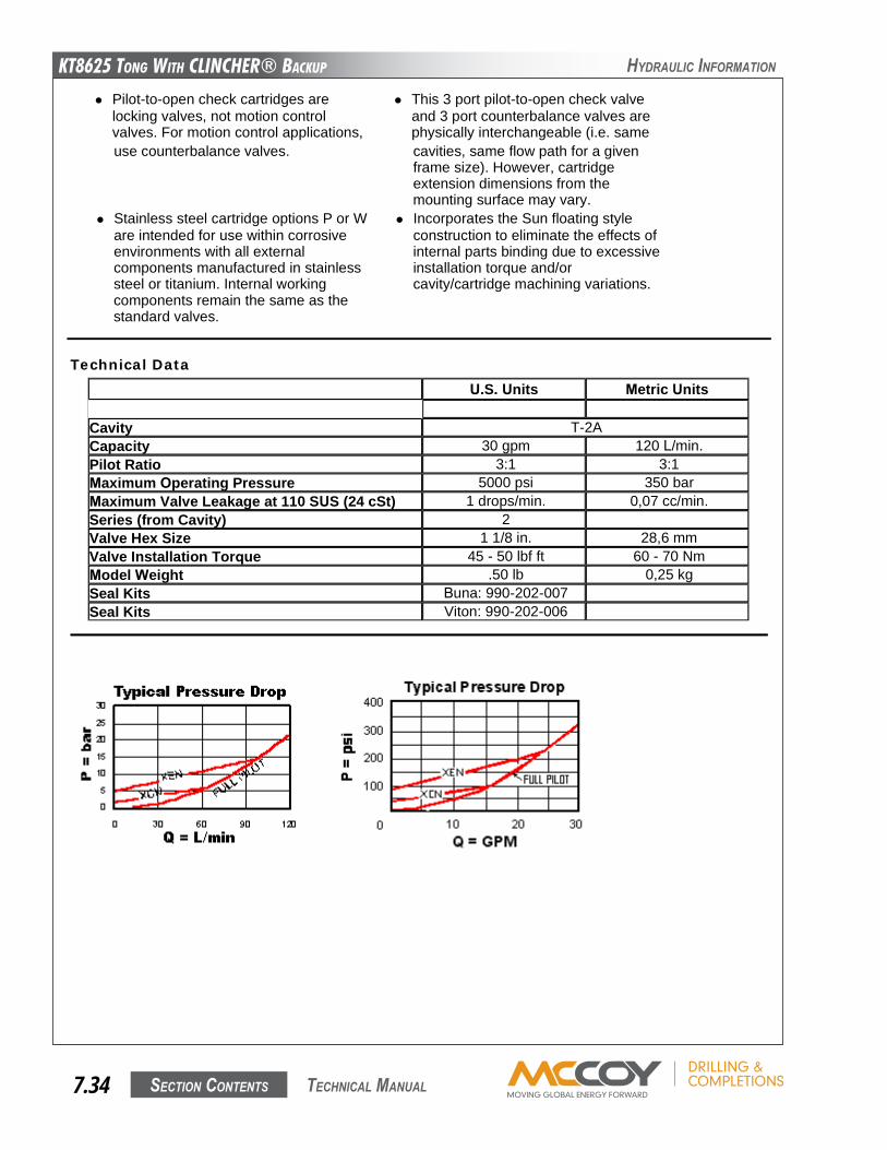
KT8625 Tong WiTh CLinChER® BaCKup
Section contentS7.34 technical Manual
hyDRaulic infoRMation
use counterbalance valves. cavities, same flow path for a givenframe size). However, cartridgeextension dimensions from themounting surface may vary.
Stainless steel cartridge options P or Ware intended for use within corrosiveenvironments with all externalcomponents manufactured in stainlesssteel or titanium. Internal workingcomponents remain the same as thestandard valves.
Incorporates the Sun floating styleconstruction to eliminate the effects ofinternal parts binding due to excessiveinstallation torque and/orcavity/cartridge machining variations.
Technical DataU.S. Units Metric Units
Cavity T-2ACapacity 30 gpm 120 L/min.Pilot Ratio 3:1 3:1Maximum Operating Pressure 5000 psi 350 barMaximum Valve Leakage at 110 SUS (24 cSt) 1 drops/min. 0,07 cc/min.Series (from Cavity) 2Valve Hex Size 1 1/8 in. 28,6 mmValve Installation Torque 45 - 50 lbf ft 60 - 70 NmModel Weight .50 lb 0,25 kgSeal Kits Buna: 990-202-007Seal Kits Viton: 990-202-006
Option Selection
CKEB-X C N
Preferred Options
Control Cracking PressureExternalMaterial/SealMaterial
X Standard Pilot C 30 psi (2 bar) N Buna-N
Pilot-to-open check valve with standard pilotCapacity:
30gpm (120 L/min.)
Functional Group:Products : Cartridges : Pilot-to-Open Check Valve : 3-Port, Non-Vented : StandardPilot, Steel Seat
Model:
CKEB
Product DescriptionThis valve is a pilot to open check valve. It has a non-sealed pilot, a steel seat, and is non-vented. It allows free flow from the valve (port 2) to the load (port 1) and blocks flow in theopposite direction. Pressure at the pilot (port 3) will open the valve from port 1 to port 2. Pilotpressure needed at port 3 to open the valve is directly proportional to the load pressure at port1. Pressure at port 2 directly opposes pilot pressure.
Technical Features Provides hose break protection,
prevents loads from drifting andpositively locks pressurized loads.
Standard unsealed pilot allows airtrapped in the pilot line to be purgedfrom the circuit.
Extremely low leakage. The seat andpoppet are heat treated for long life. Ifthe load drifts due to the valve, the seathas probably been damaged bycontamination and the valve should bereplaced.
Optional external porting out of the hexend of the cartridge is available forexternal piloting. In this configuration,port 3 is blocked. See Control optionsE, and P.
Pilot-to-open check cartridges arelocking valves, not motion controlvalves. For motion control applications,
This 3 port pilot-to-open check valveand 3 port counterbalance valves arephysically interchangeable (i.e. same