hds-6 / e hr-6 - furman power · hds-6/hr-6 headphone distribution system linking hds-6 to hr-6s...
TRANSCRIPT
HEADPHONE DISTRIBUTION SYSTEM AND PERSONAL HEADPHONE MIXER
HDS-6 / E HR-6
HEADPHONE MONITORING SERIES

HDS-6/HR-6 HEADPHONE DISTRIBUTION SYSTEM
INTRODUCTION
Thank you for your purchase of a
Furman HDS-6 Headphone Distribution System
and HR-6 Personal Headphone Mixer* – and
congratulations on your choice. We based this
system on our own experiences with major
recording projects and studios. You now own
a headphone system that will make all of your
sessions flow more smoothly.
Please read this manual before using your HDS-6/HR-6 system.
FEATURES● Every artist in the studio can have a
personalized headphone mix.
● It’s perfect for tracking, overdubbing and rehearsal sessions.
● The HDS-6 rackmount distribution system quickly and easily connects to any studio console or patch bay. It provides the interface to drive a chain of HR-6 personal headphone mixers.
● Each HR-6 remote mixing station provides each musician five volume controls: four monaural (for mixer channels or busses), one for the stereo mix or stereo effects mix, and a button to mute all but the stereo channel.
● Inexpensive Ethernet-CAT5 computer cables are used to link the HDS-6 to HR-6s, and HR-6 mixing stations to other HR-6s.
● The HDS-6 also features an On-Off switch, power-on LED and a Signal Overload LED for each chan-nel. Other features include an LED to indicate Link Cables Reversed, Ground Lift switch, signal inputs and outputs, and HR-6 link connectors.
1
*HDS-6 and HR-6 are sold seperately

HDS-6/HR-6 HEADPHONE DISTRIBUTION SYSTEM
DESCRIPTIONThe Furman Headphone Distribution System is easy to set up, and makes your music sound great. It provides custom headphone mixes to a number of people in recording and rehearsal environments.
The system consists of the rackmount HDS-6 Headphone Distribution System, and one or more Furman HR-6 Personal Headphone Mixers.
The HDS-6 distribution system is designed spe-cifically as a low-distortion line driver and power supply for the most critical listening situations. The HDS-6 typically connects to a mixing console and provides both the interface and power to drive a chain of HR-6 mixing stations. Since the HDS-6 provides signal, power and ground to the HR-6 remote mixers, you don’t have to worry about locating your HR-6 remote mixing stations near an AC power outlet.
Up to eight HR-6 mixing stations can be linked to the HDS-6 (depending on headphone type and impedance) and multiple HR-6s are easily daisy-chained. You can even plug two headphones into one HR-6. Please note that if you do, both head-phones should be the same brand and model. If they’re not, their listening levels probably won’t be the same. Every musician plugged into an HR-6 mixing station can create his or her own custom mix without assistance from the engineer in the control room.
The HR-6 mixing station is compact, lightweight and designed to clamp onto a mic stand. It pro-vides a volume control for each of its four mono channels, and a fifth volume control – assigned to both the left and right – inputs the stereo chan-nel. The stereo pot will most often be used for the main control room mix, or for stereo effects from the console. You can instead choose to use the left and right inputs on the HDS-6 for two more mixer
channels or busses if you wish. Just remember that the listening level of both inputs will be con-trolled by only one volume control.
The HR-6 personal mixer provides another very useful feature: the “Submixes Included/Excluded” button. This button mutes the four monaural channels. This means every HR-6 user can hear the stereo source only, without having to alter the HR-6’s four monaural settings. This is very helpful when all musicians wish to hear playback of a control-room mix.
CONNECTING THE HDS-6Since the HDS-6/HR-6 system will be used most often for studio tracking and playback, it is designed to be direct-out patchable with mixing consoles. If your system has a patch bay, we sug-gest you connect the HDS-6 to it instead of your console.
The HDS-6 has balanced TRS inputs, so balanced outputs work best, but standard 1/4" phone-plug cables will work fine too. Just connect the direct-out of a mixer channel strip or buss to an input of the HDS-6 and connect any stereo output of the mixer to the stereo inputs on the HDS-6. Remember, you can use the HDS-6 Left-Right stereo inputs for two more mono channels or busses from your console if your prefer.
CONNECTING THE HR-6The HDS-6 connects to an HR-6 with two stan-dard (10 base-T UTP) Ethernet-CAT5 cables. Two cables, coded blue and gray and each 25 feet in length, come with your HR-6; additional cables are available from Furman.
Please see the following drawings.
2
HDS-6/HR-6 HEADPHONE DISTRIBUTION SYSTEM
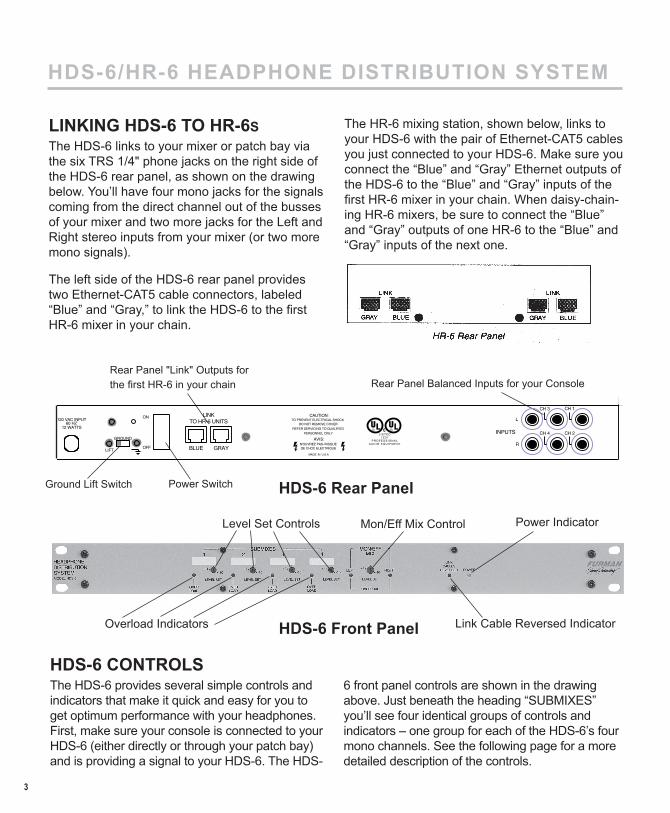
LINKING HDS-6 TO HR-6SThe HDS-6 links to your mixer or patch bay via the six TRS 1/4" phone jacks on the right side of the HDS-6 rear panel, as shown on the drawing below. You’ll have four mono jacks for the signals coming from the direct channel out of the busses of your mixer and two more jacks for the Left and Right stereo inputs from your mixer (or two more mono signals).
The left side of the HDS-6 rear panel provides two Ethernet-CAT5 cable connectors, labeled “Blue” and “Gray,” to link the HDS-6 to the fi rst HR-6 mixer in your chain.
The HR-6 mixing station, shown below, links to your HDS-6 with the pair of Ethernet-CAT5 cables you just connected to your HDS-6. Make sure you connect the “Blue” and “Gray” Ethernet outputs of the HDS-6 to the “Blue” and “Gray” inputs of the fi rst HR-6 mixer in your chain. When daisy-chain-ing HR-6 mixers, be sure to connect the “Blue” and “Gray” outputs of one HR-6 to the “Blue” and “Gray” inputs of the next one.
3
Rear Panel "Link" Outputs for the fi rst HR-6 in your chain Rear Panel Balanced Inputs for your Console
Power SwitchGround Lift Switch
Power IndicatorLevel Set Controls
Overload Indicators
Mon/Eff Mix Control
Link Cable Reversed Indicator
HDS-6 CONTROLSThe HDS-6 provides several simple controls and indicators that make it quick and easy for you to get optimum performance with your headphones. First, make sure your console is connected to your HDS-6 (either directly or through your patch bay) and is providing a signal to your HDS-6. The HDS-
6 front panel controls are shown in the drawing above. Just beneath the heading “SUBMIXES” you’ll see four identical groups of controls and indicators – one group for each of the HDS-6’s four mono channels. See the following page for a more detailed description of the controls.
L
R
CH 2CH 4INPUTS
CH 1CH 3CAUTION:
TO PREVENT ELECTRICAL SHOCKDO NOT REMOVE COVER
REFER SERVICING TOQUALIFIEDPERSONNEL ONLY
N’OUVREZ PAS RISQUEDE CHOC ELECTRIQUE
LISTED7Z37
PROFESSIONALAUD IO EQU IPMENT
AVIS:GROUND
LIFT
ON
OFF
LINKTO HR-6 UNITS
GRAYBLUE
120 VAC INPUT60 HZ
12 WATTS
MADE IN U.S.A.
HDS-6 Rear Panel
HDS-6 Front Panel

HDS-6/HR-6 HEADPHONE DISTRIBUTION SYSTEM
LEVEL SET Control: This small trim pot controls the amount of gain the HR-6 applies to the signal from your console before the signal is sent. The control is designed to be adjusted by a small screwdriver to prevent accidental changes of its setting during tracking or playback. The proper setting of this con-trol is accomplished with the help of the “Overload” LED. A white label area is provided for each of the four mono channels to allow you to write down the program source from your console. Use a grease pencil for easy erasability.
OVERLOAD Indicators: To get the best signal-to-noise ratio and maximum headroom, refer to this LED while calibrating your HDS-6’s gain controls. If this red LED is glowing constantly, your HDS-6 gain is set too high. Conversely, if this red LED doesn’t glow at all, your HDS-6 gain is set too low. What you want to see is the LED glowing oc-casionally, on the loudest peaks only.
MON/EFF MIX Control: This trim-type screwdriver pot controls the gain for the Left-Right stereo inputs of the HDS-6. Both the Left and Right program sources are affected identically with this control. Two OVERLOAD indicators are also provided for this stereo pair. As with the overload indicators for each of the HDS-6 four mono chan-nels, you’ll want to adjust the gain control so that the LEDs marked “Left” and “Right” are glowing
just some of the time. Also, they should glow at the same intensity. If you notice that the LEDs marked “Left” and “Right” are not glowing at the same intensity, you may need to adjust the output from your console.
LINK CABLE REVERSED Indicator: As mentioned earlier, it is necessary to connect the “Blue” and “Gray” Ethernet cable outputs of the HDS-6 to the corresponding inputs of the first HR-6 in your chain of HR-6 mixers, and to follow the same pro-cedure when daisy-chaining multiple HR-6 mix-ers. If you accidentally reverse the color-coded cables when connecting, don’t worry. The LINK CABLE REVERSED indicator on the HDS-6 will light up to alert you. Simply reconnect any cables that are reversed.
POWER Indicator: This front panel LED glows when the HDS-6 is on.
POWER Switch: It is on the HDS-6 rear panel.
GROUND LIFT Switch: This rear panel switch takes the audio ground off the chassis ground, which can prevent buzz or hum caused by ground loops. This switch does not affect the AC safety ground of the HDS-6. Under no circumstances should you ever remove the third prong on your HDS-6’s AC plug.
4
Up to eight HR-6s can be daisy chained depending on the impedence of your head-phones.
(To Mixer Effects Return)
(To HDS-6 Stereo Inputs)

HDS-6/HR-6 HEADPHONE DISTRIBUTION SYSTEM
HR-6 CONTROLSNow that you have your HDS-6 connected to your console, and your chain of HR-6 mixing stations is connected to your HDS-6, the fun begins.
Here’s all you need to know to create a custom headphone mix with an HR-6:
SUBMIXES Volume Controls: The front panel of the HR-6 mixer provides one volume control for each of the four mono channels arriving at the HR-6 from your console and HDS-6 Distribution System.
MON/EFF Volume Control: This single control simultaneously adjusts the level of the stereo main mix (or stereo effects returns, or two more channel strips of busses) arriving at the HR-6 from your console through the HDS-6. Remem-ber: If you use the HDS-6’s Left-Right inputs to accommodate two or more console channels or busses instead of one stereo signal, the volume levels of both console channels or busses will be adjusted by this control. These two inputs will not be individually adjustable for loudness as the four mono channels are.
SUBMIXES “INCLUDED/EXCLUDED” Button: This feature allows each musician to hear (for ex-ample) only the main mix coming from the control room. The button mutes the four mono controls, allowing each HR-6 user to hear stereo source only without having to turn down the HR-6’s four mono volume knobs.
HEADPHONE OUTPUTS: The HR-6 provides two 1/4" stereo headphone jacks. You may plug two headphones into one HR-6, but unless both are the same brand and model one headphone is likely to not be as loud as the other.
Each HR-6 also comes with hardware to clamp the HR-6 on a mic stand. The HR-6 also provides erasable white label areas to jot down the signal source for each of its four mono channels. Use a grease pencil for easy erasability.
LINK CABLE REVERSED Indicator: As men-tioned earlier, you need to connect the “Blue” and “Gray” Ethernet cable outputs of the HDS-6 to the corresponding inputs of the first HR-6. These corresponding inputs must remain consistent with each subsequent HR-6 mixer. If you accidentally reverse the color-coded cables, don’t worry. The LINK CABLE REVERSED indicator on the lower left corner of the HR-6 will alert you. Simply recon-nect any cables that are reversed.
5

HDS-6/HR-6 HEADPHONE DISTRIBUTION SYSTEM
ONE- TO THREE-YEAR LIMITED WARRANTY Furman Sound, Inc., having its principal place of business at 1997 South McDowell Blvd., Peta-luma, CA 94954 (“Manufacturer”) warrants its HDS-6/HR-6 (the “Product”) as follows:
Manufacturer warrants to the original Purchas-er of the Product that the Product sold hereunder will be free from defects in material and work-manship for a period of three years from the date of purchase. The Purchaser of the product is allowed fifteen days from the date of purchase to complete warranty registration by mail or on-line at the Furman website. If the Product does not conform to this Limited Warranty during the war-ranty period (as herein above specified), Pur-chaser shall notify Manufacturer in writing of the claimed defects. If the defects are of such type and nature as to be covered by this warranty, Manufacturer shall authorize Purchaser to return the Product to the Furman factory or to an au-thorized Furman repair location. Warranty claims should be accompanied by a copy of the original purchase invoice showing the purchase date; this is not necessary if the Warranty Registration was completed either via the mailed in warranty card or on-line website registration. Shipping charges to the Furman factory or to an authorized repair location must be prepaid by the Purchaser of the product. Manufacturer shall, at its own expense, furnish a replacement Product or, at Manufactur-er’s option, repair the defective Product. Return shipping charges back to Purchaser will be paid by Manufacturer.
THE FOREGOING IS IN LIEU OF ALL OTHER WARRANTIES, EXPRESS OR IMPLIED, IN-CLUDING BUT NOT LIMITED TO THE IMPLIED WARRANTIES OF MERCHANTABILITY AND FITNESS FOR A PARTICULAR PURPOSE. Manufacturer does not warrant against damages
6
or defects arising out of improper or abnormal use of handling of the Product; against defects or damages arising from improper installation, against defects in products or components not manufactured by Manufacturer, or against dam-ages resulting from such non-Manufacturer made products or components. This warranty shall be cancelable by Manufacturer at its sole discre-tion if the product is modified in any way without written authorization from Furman Sound. This warranty also does not apply to Products upon which repairs have been affected or attempted by persons other than pursuant to written authoriza-tion by Manufacturer.
THIS WARRANTY IS EXCLUSIVE. The sole and exclusive obligation of Manufacturer shall be to repair or replace the defective Product in the manner and for the period provided above. Manufacturer shall not have any other obligation with respect to the Products or any part thereof, whether based on contract, tort, strict liability or otherwise. Under no circumstances, whether based on this Limited Warranty or otherwise, shall Manufacturer be liable for incidental, special, or consequential damages. Manufacturer’s em-ployees or representatives’ ORAL OR OTHER WRITTEN STATEMENTS DO NOT CONSTI-TUTE WARRANTIES, shall not be relied upon by Purchaser, and are not a part of the contract for sale or this limited warranty. This Limited Warran-ty states the entire obligation of Manufacturer with respect to the Product. If any part of this Limited Warranty is determined to be void or illegal, the remainder shall remain in full force and effect.

HDS-6/HR-6 HEADPHONE DISTRIBUTION SYSTEM
SERVICEBefore returning any equipment for repair, please be sure that it is adequately packed and cushioned against damage in shipment, and that it is insured. We suggest that you save the original packaging and use it to ship the product for servicing. Also, please enclose a note including your name, address, phone number and a description of the problem.
NOTE: All equipment being returned for repair must have a Return Authorization (R/A) Num-ber. To get an R/A Number, please call the Furman Service Department: (707) 763-1010, ext. 120 or 121. Please display your R/A Num-ber prominently on the front of all packages.
Furman Sound, Inc.1997 South McDowell Blvd.
Petaluma, California 94954-6919 USAPhone: 707-763-1010
Fax: 707-763-1310Web: www.furmansound.com
E-mail: [email protected] in China100803-E
HDS-6 / HR-6 SPECIFICATIONSINPUTS:
Input Impedance: 20K ohms.
Sensitivity: Variable, -10 to +4 dBu for rated output.
CONNECTORS:HDS-6 Inputs: 1/4" phone, balanced or unbalanced.
HDS-6 to HR-6 Link Connectors: RJ-45 jacks.
HR-6 to HR-6 Link Connectors: RJ-45 jacks.
HR-6 Outputs: Two 1/4" headphone jacks. Up to eight HR-6s can be daisy-chained from HDS-6 depending on the impedance of headphones used.
HDS-6 / HR-6 Connecting Cable: 10 Base-T UTP Ethernet-CAT5 computer cables, Cat. 3 or better.
GENERAL:Power Out: 400 mW at 32 ohms (200 mW at 600 ohms, 500 mW at 100 ohms).
Distortion: 0.008% THD at full-rated power at 1 KHz; 0.05% THD 20Hz to 20 KHz.
Dynamic Range: Greater than 96 dB
Frequency Response: +0, -1 dB from 20 Hz to 20 KHz, 400 mW output.
Power Requirement: 120 VAC, 60 Hz, (E-Version: 230 VAC, 50 Hz) 20 watts
Mechanical: HDS-6 Dimensions: 1.75" H x 19" W x 7.25" D.
HDS-6 Weight: 6.8 lbs (3.1 kg)
HR-6 Dimensions: 2.5" H x 6.75" W x 3.5"D.
HR-6 Weight: 1.25 lbs (.58 kg)
NOTE:0 dBu equals .775 Vrms.