hdtv satellite broadcasting in the ehf …eprints.biblio.unitn.it/3991/1/techrep024.pdf ·...
TRANSCRIPT
DISI - Via Sommarive 14 - 38123 Povo - Trento (Italy) http://www.disi.unitn.it
HDTV SATELLITE BROADCASTING
IN THE EHF DOMAIN: FEASIBILITY
STUDY AND QUALITY ASSESSMENT
Nicola Conci, Tommaso Rossi, and Claudio
Sacchi
June 2012
Technical Report # DISI-12-024


1
HDTV satellite broadcasting in the EHF domain:Feasibility Study and Quality Assessment
Nicola Conci, Tommaso Rossi, and Claudio Sacchi
Abstract
In this work we propose a simulation-based feasibility study for the efficient exploitation of W band (75-110GHz) for high quality HDTV broadcasting applications. In order to obtain a reliable and realistic simulationenvironment, we have considered the DVB-S2 standard specifications, introducing the typical W-band impairmentssuch as phase noise, rain attenuation, as well as non-linearities. For testing purposes, we have adopted common High-Definition benchmark video sequences, so as to evaluate the H.264 video quality as a function of the available bit-rateon the channel. During the simulation phase we have taken into account adaptive techniques like ACM (AdaptiveCoding and Modulation) and scalable video coding (SVC). Eventually, we have evaluated the achieved results inview of implementing future broadcasting services in the EHF domain. Simulation results have demonstrated thesuitability of W-band to efficiently support a reliable HDTV service with an increased number of available channelsif compared to DVB-S2 standard using Ku and Ka band. The large bandwidth availability should also improvethe system flexibility in terms of trade-off between spectral efficiency and video quality.
Index Terms
DVB-S2, HDTV, Satellite Broadcasting, Adaptive Code Modulation, EHF.
I. INTRODUCTION
The introduction of digital TV transmission has allowed for a consistent increment of degrees offreedom thanks to adaptive modulations, joint source and channel coding, scalable source coding, as wellas adaptive error concealment, which have permitted a more efficient bandwidth usage. As also statedin [1], the set of crucial parameters that characterize the TV broadcasting service are represented by (i)orbital position, (ii) transponder bandwidth, (iii) power coverage, and (iv) service availability.
In addition, we have also to take into account the desired output of the transmission, both in terms ofperceived quality, and in terms of available channels delivered to the users.
Recently, the TV broadcasting standardization bodies have been concentrating on the DVB. In particularthe DVB-S system is based on Quadrature Phase Shift Keying (QPSK) modulation couple with convo-lutional channel coding, and concatenated with Reed-Solomon coding. The satellite channels for DVB-Shave been identified in the Ku-band (11-14 GHz). The Ku band exhibits favorable atmospheric attenuationconditions, as also reported by the intensive tests carried out during the five-year SIRIO measurementcampaign (1978-1982) [2]. The last evolution of the DVB-S standard is represented by DVB-S2, nowrecognized as ITU-R and ETSI standard [3]. DVB-S2 extended the DVB-S functionalities to includehigher-order modulations and adaptive coding and modulation (ACM). DVB-S2 has been designed to fulfillthe requirements of different types of applications, including (i) broadcasting of standard definition andhigh-definition TV (SDTV and HDTV), (ii) interactive services including Internet access, (iii) professionalapplications (e.g. news gathering), as well as (iv) data content distribution and Internet trunking.
The question that naturally comes to mind is whether Ku and Ka-band frequency spaces are compatibleand large enough to efficiently support the constantly increasing number of high-quality digital TVand HDTV channels as required by the market. In such a framework, recent experiments of satellite
Nicola Conci, and Claudio Sacchi are with the Department of Information Engineering and Computer Science, University of Trento, ViaSommarive 5, 38123 - Povo di Trento, Italy. email: {conci, sacchi}@disi.unitn.it
Tommaso Rossi is with the Department of Electronic Engineering, University of Rome “Tor Vergata”, Via del Politecnico 1, 00133 Rome,Italy. email: [email protected]
2
Extremely High Frequency (EHF) communications [4] like ALPHASAT, DAVID and WAVE, are exploringunexploited spectrum portions in the EHF domain in order to find additional bandwidth resources forbroadband satellite communications. The analysis carried out in literature [5], [6], [7] evidenced twofavorable frequency windows for EHF satellite transmission, i.e. Q-V band (30-50 GHz) and W-band(75-110 GHz).
A preliminary work about optimization of DVB-S2 links in W-band has been recently proposed in [8].Simulations including rain fading and amplifier nonlinearities have been performed in order to select theproper thresholds for the different Adaptive Coding and Modulation (ACM) modes considered by DVB-S2standard.
Our work aims at providing an improvement with respect to the previous work of [8], by extending theanalysis to the transmission and the reception of the coded digital TV signal. In this paper, we simulate acomplete end-to-end satellite W-band link for DVB-S2 broadcasting that includes phase noise, amplifiernonlinearities, and rain fading. We also address the issue of evaluating the impact of link attenuation anddistortion on the digital signal, measuring the quality of the video received at the destination. Besidesassessing the performance achievable by the DVB-S2 standard in a W-band transmission scenario, it is alsonecessary to propose realistic solutions to improve the quality of the received video signals in presence ofheavy channel attenuation. The proposed study will consider the increased bandwidth availability naturallyprovided by W-band with respect to Ku and Ka band, in order to design an effective transmission link.
The paper is structured as follows: Section 2 describes the DVB-S2 W-band satellite broadcastingsystem, Section 3 is devoted at presenting the DVB-S2 physical layer simulation, and Section 4 detailsthe video coding procedures adopted for efficient HDTV broadcasting in the framework of DVB-S2standard. Section 5 introduces the simulation strategies chosen to model and simulate the impairments inthe W-band link. Experimental results will be shown in Section 6, while concluding remarks are drawnin Section 7.
II. SYSTEM DESCRIPTION
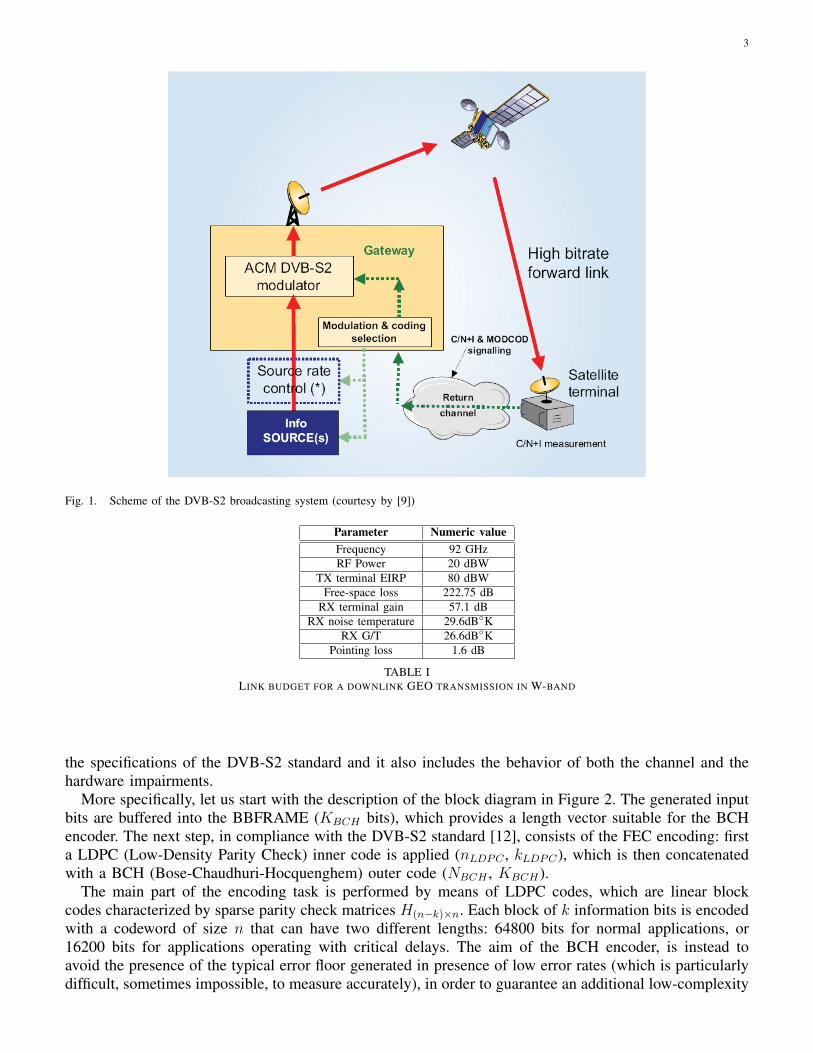
The analysis we present here provides a qualitative evaluation of the performances of an HDTVbroadcasting application with reference to the downlink channel (the “high bit-rate forward link” in Fig.1) of a geostationary satellite operating in the EHF domain, and in the W-band in particular. Fig. 1 brieflysummarizes the typical structure of a DVB-S2 system in the ACM configuration.
The most attractive feature of the W-band compared to other frequency bandwidths such as the Ku-band, consists of the larger bandwidth availability. Once demonstrated that the strong limitations due tothe atmospheric attenuations can be overcome using state-of-art error resilience tools, we can devise apossible frequency plan for the W-band and compare it with a Ku-based system: given the example of theASTRA 1H satellite for broadcast services [10], the typical transponder bandwidth for Ku transmission isabout 33 MHz and the overall bandwidth availability is about 1GHz; estimating an overall bandwidth ofabout 15 GHz or even more for the W-band, a reasonable bandwidth allocation for a single transpondercan be in the range of about 500 MHz. This turns out to be an evident advantage, first of all in terms ofnumber of channels per transponder but also because it allows employing a higher bit-rate for the TDMA,thus limiting the typical problems related both to the narrower transponder of the Ku band and to theFDMA systems (e.g. intermodulation interference, high back-off levels and so on).
As a reference system for the link budget equation we used the data provided in [11] (included forthe sake of completeness in Table I) for a geostationary high-bit-rate satellite system, transmitting on aW-band downlink.
III. DVB-S2 PHYSICAL LAYER SIMULATION
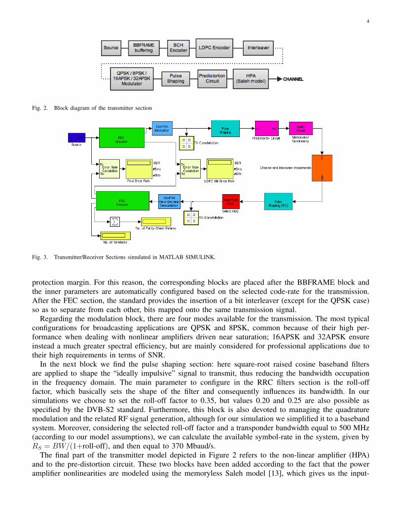
The physical layer we have adopted represents a satellite broadcasting system operating on a W-bandlink. The block diagram of the transmitter section is shown in Figure 2. The system has been implementedusing the software MATLAB SIMULINK 2007. The simulation model, shown in Figure 3 is based on
3
Fig. 1. Scheme of the DVB-S2 broadcasting system (courtesy by [9])
Parameter Numeric valueFrequency 92 GHzRF Power 20 dBW
TX terminal EIRP 80 dBWFree-space loss 222.75 dB
RX terminal gain 57.1 dBRX noise temperature 29.6dB◦K
RX G/T 26.6dB◦KPointing loss 1.6 dB
TABLE ILINK BUDGET FOR A DOWNLINK GEO TRANSMISSION IN W-BAND
the specifications of the DVB-S2 standard and it also includes the behavior of both the channel and thehardware impairments.
More specifically, let us start with the description of the block diagram in Figure 2. The generated inputbits are buffered into the BBFRAME (KBCH bits), which provides a length vector suitable for the BCHencoder. The next step, in compliance with the DVB-S2 standard [12], consists of the FEC encoding: firsta LDPC (Low-Density Parity Check) inner code is applied (nLDPC , kLDPC), which is then concatenatedwith a BCH (Bose-Chaudhuri-Hocquenghem) outer code (NBCH , KBCH).
The main part of the encoding task is performed by means of LDPC codes, which are linear blockcodes characterized by sparse parity check matrices H(n−k)×n. Each block of k information bits is encodedwith a codeword of size n that can have two different lengths: 64800 bits for normal applications, or16200 bits for applications operating with critical delays. The aim of the BCH encoder, is instead toavoid the presence of the typical error floor generated in presence of low error rates (which is particularlydifficult, sometimes impossible, to measure accurately), in order to guarantee an additional low-complexity
4
Fig. 2. Block diagram of the transmitter section
Fig. 3. Transmitter/Receiver Sections simulated in MATLAB SIMULINK.
protection margin. For this reason, the corresponding blocks are placed after the BBFRAME block andthe inner parameters are automatically configured based on the selected code-rate for the transmission.After the FEC section, the standard provides the insertion of a bit interleaver (except for the QPSK case)so as to separate from each other, bits mapped onto the same transmission signal.
Regarding the modulation block, there are four modes available for the transmission. The most typicalconfigurations for broadcasting applications are QPSK and 8PSK, common because of their high per-formance when dealing with nonlinear amplifiers driven near saturation; 16APSK and 32APSK ensureinstead a much greater spectral efficiency, but are mainly considered for professional applications due totheir high requirements in terms of SNR.
In the next block we find the pulse shaping section: here square-root raised cosine baseband filtersare applied to shape the “ideally impulsive” signal to transmit, thus reducing the bandwidth occupationin the frequency domain. The main parameter to configure in the RRC filters section is the roll-offfactor, which basically sets the shape of the filter and consequently influences its bandwidth. In oursimulations we choose to set the roll-off factor to 0.35, but values 0.20 and 0.25 are also possible asspecified by the DVB-S2 standard. Furthermore, this block is also devoted to managing the quadraturemodulation and the related RF signal generation, although for our simulation we simplified it to a basebandsystem. Moreover, considering the selected roll-off factor and a transponder bandwidth equal to 500 MHz(according to our model assumptions), we can calculate the available symbol-rate in the system, given byRS = BW/(1+roll-off), and then equal to 370 Mbaud/s.
The final part of the transmitter model depicted in Figure 2 refers to the non-linear amplifier (HPA)and to the pre-distortion circuit. These two blocks have been added according to the fact that the poweramplifier nonlinearities are modeled using the memoryless Saleh model [13], which gives us the input-
5
output relations both for amplitude (AM/AM conversion)
A(r) =k1k2α1r
1 + β1k21r2
(1)
and phase (AM/PM conversion) [8].
Φ(r) =k21α2r
2
1 + β2k21r2
(2)
According to Eq. (1) and (2), r is the magnitude of the input signal, simulation values k1 and k2 areset to 4 and 30, respectively, while α1, β1, α2 and β2 are taken to be 2.1587, 1.1517, 4.0033 and 9.1807,respectively.
The pre-distortion circuit placed ahead of the amplifier is composed by an amplitude compensator(only needed for 16APSK and 32APSK modulations), a phase compensator (to make up for phase shift inconstellations) and an attenuator (to ensure that the amplifier is not driven into saturation). In particular,the latter is given by:
k3 =G
k1k2=
α1
2k1xmax√β1
(3)
that corresponds to the ratio of the obtained gain (about 29 dB, depending on xmax) to the maximumpossible gain when β1 is zero (about 41 dB). Thus, using a pre-distorter that calculates the reverse transferfunction of the Saleh equation, it is possible to reach a consistent amount of gain at the output of theamplifier with a reasonably low level of distortion.
As far as the receiver is concerned, it is mainly composed of the specular blocks of the transmitter,with the only exception of the AGC (Automatic Gain Control) positioned before the demodulator, neededto adjust the input gain.
IV. VIDEO CODING AND VIDEO QUALITY ASSESSMENT
The DVB-S2 system does not impose any restriction in terms of video coding standards to be adoptedfor video delivery. For this work, in accordance to the current state of art in video coding, we have chosenH.264/AVC [14], because of the high performance with respect to its predecessors.
As we stated at the beginning of this paper, one of the main purposes of this work is to evaluatethe transmission of HDTV video streams in a particular range of the frequency spectrum. We have thusanalyzed four different HD sequences, using different configurations of the encoder (x264 - an open sourcesoftware for video encoding in H.264 [15]), and evaluating the obtained video quality by measuring theSSIM index (Structural Similarity Index Metric) [16], a full-reference objective metric that better correlatesthe visual artifacts to the human visual perception, with respect to more common metrics such as the PeakSignal to Noise Ratio (PSNR).
The selected HD sequences are in 720P format and analyzed at both 25 and 50 fps. Given the difficultiesof finding uncompressed HD sequences, for testing purposes we have used HD movie trailers, alreadycompressed in H.264 format at high quality. The reason that lead us to the choice of movie trailers, isthat they can reasonably well approximate the average statistics of an entire movie, so that we can workwith relatively short sequences with a good approximation of the full length movies.
The sequences we have chosen for simulation are:• Cartoon - a movie trailer from a famous cartoon produced by Disney Pixar, rich of details and
colors, duration 2 min 23 sec, resolution 1280× 720;• Action movie - a movie trailer containing some fast and particularly critical (for the encoder) scenes,
duration 1 min 58 sec, resolution 1280× 608;• Movie - a trailer from a typical movie with slow/medium motion scenes, duration 2 min 30 sec,
resolution 1280× 544;• Action scene - an additional video extracted from a pretty fast and complex two minute scene of a
movie, in order to have a “worst case” sequence to test, resolution 1280× 532.
6
A first set of tests has been carried out in order to analyze the video quality and the output bit-rate asfunction of the quantization parameter of the x264 encoder.
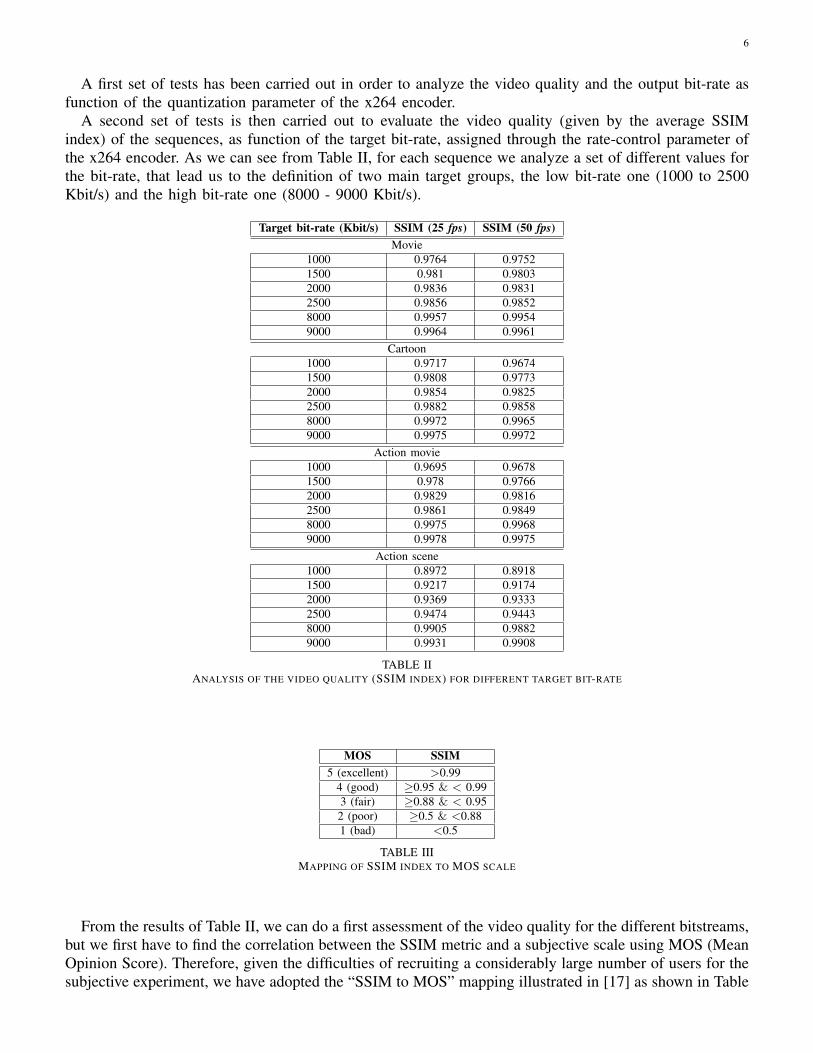
A second set of tests is then carried out to evaluate the video quality (given by the average SSIMindex) of the sequences, as function of the target bit-rate, assigned through the rate-control parameter ofthe x264 encoder. As we can see from Table II, for each sequence we analyze a set of different values forthe bit-rate, that lead us to the definition of two main target groups, the low bit-rate one (1000 to 2500Kbit/s) and the high bit-rate one (8000 - 9000 Kbit/s).
Target bit-rate (Kbit/s) SSIM (25 fps) SSIM (50 fps)Movie
1000 0.9764 0.97521500 0.981 0.98032000 0.9836 0.98312500 0.9856 0.98528000 0.9957 0.99549000 0.9964 0.9961
Cartoon1000 0.9717 0.96741500 0.9808 0.97732000 0.9854 0.98252500 0.9882 0.98588000 0.9972 0.99659000 0.9975 0.9972
Action movie1000 0.9695 0.96781500 0.978 0.97662000 0.9829 0.98162500 0.9861 0.98498000 0.9975 0.99689000 0.9978 0.9975
Action scene1000 0.8972 0.89181500 0.9217 0.91742000 0.9369 0.93332500 0.9474 0.94438000 0.9905 0.98829000 0.9931 0.9908
TABLE IIANALYSIS OF THE VIDEO QUALITY (SSIM INDEX) FOR DIFFERENT TARGET BIT-RATE
MOS SSIM5 (excellent) >0.99
4 (good) ≥0.95 & < 0.993 (fair) ≥0.88 & < 0.952 (poor) ≥0.5 & <0.881 (bad) <0.5
TABLE IIIMAPPING OF SSIM INDEX TO MOS SCALE
From the results of Table II, we can do a first assessment of the video quality for the different bitstreams,but we first have to find the correlation between the SSIM metric and a subjective scale using MOS (MeanOpinion Score). Therefore, given the difficulties of recruiting a considerably large number of users for thesubjective experiment, we have adopted the “SSIM to MOS” mapping illustrated in [17] as shown in Table
7
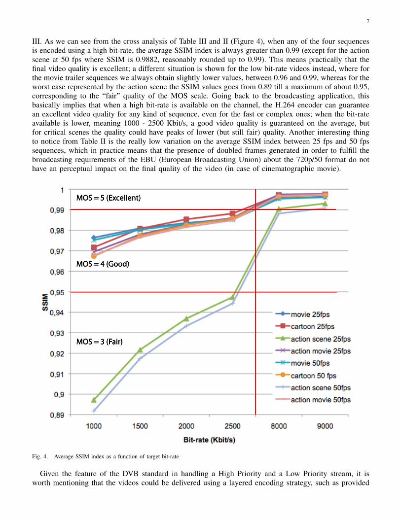
III. As we can see from the cross analysis of Table III and II (Figure 4), when any of the four sequencesis encoded using a high bit-rate, the average SSIM index is always greater than 0.99 (except for the actionscene at 50 fps where SSIM is 0.9882, reasonably rounded up to 0.99). This means practically that thefinal video quality is excellent; a different situation is shown for the low bit-rate videos instead, where forthe movie trailer sequences we always obtain slightly lower values, between 0.96 and 0.99, whereas for theworst case represented by the action scene the SSIM values goes from 0.89 till a maximum of about 0.95,corresponding to the “fair” quality of the MOS scale. Going back to the broadcasting application, thisbasically implies that when a high bit-rate is available on the channel, the H.264 encoder can guaranteean excellent video quality for any kind of sequence, even for the fast or complex ones; when the bit-rateavailable is lower, meaning 1000 - 2500 Kbit/s, a good video quality is guaranteed on the average, butfor critical scenes the quality could have peaks of lower (but still fair) quality. Another interesting thingto notice from Table II is the really low variation on the average SSIM index between 25 fps and 50 fpssequences, which in practice means that the presence of doubled frames generated in order to fulfill thebroadcasting requirements of the EBU (European Broadcasting Union) about the 720p/50 format do nothave an perceptual impact on the final quality of the video (in case of cinematographic movie).
MOS = 5 (Excellent)
MOS = 4 (Good)
MOS = 3 (Fair)
Fig. 4. Average SSIM index as a function of target bit-rate
Given the feature of the DVB standard in handling a High Priority and a Low Priority stream, it isworth mentioning that the videos could be delivered using a layered encoding strategy, such as provided
8
by the H.264/AVC extension called SVC (Scalable Video Coding), that we considered for our evaluationson the possible broadcasting scenarios (in Section VI) [18]. Scalable video coding enables in practiceto broadcast the whole stream, giving though the possibility to the end-user to decode only a subset ofrelevant information, depending on the channel availability or the device features. In other words, weassume to encode our HDTV video stream using a “quality scalability” and to achieve this we considereda main bitstream consisting of an High Priority (HP) subset stream, transmitted by the DVB-S2 systemusing a highly protective mode and therefore having a smaller bit-rate, and of a Low Priority (LP) subsetstream that can be transmitted using a lower degree of protection. What we expect in the decoding phaseis to experience an excellent video quality when the whole bitstream (both HP and LP streams) is receivedcorrectly at the decoder, and a fairly good quality instead when only the HP stream is available at thereceiver.
V. SIMULATION STRATEGIES
In our system we simulate a 500 MHz transponder in the W-band satellite link, in order to measurethe service availability of the channel both in terms of service time and bit-rate. In addition, we alsoinvestigate the number of HDTV channels that could be transmitted as the bit-rate capacity varies.
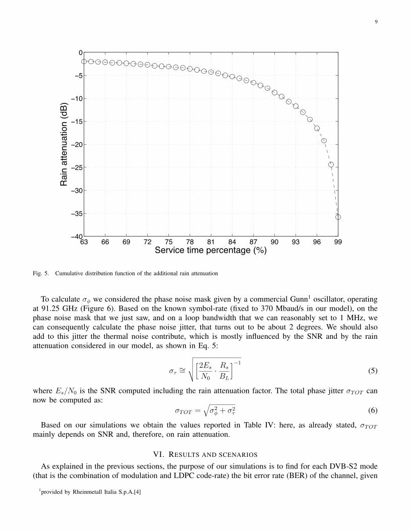
The most important task of the simulator for the characterization of the satellite link and the relatedhardware problems, is in modeling the channel and the RF device impairments. We have identified threemain processing blocks to achieve this goal: the first one simply adds the atmospheric attenuation due torain events, the second is the AWGN noise block, and the third one manages the additional phase jitterdue to phase noise and thermal noise. Rain attenuations, and more in general atmospheric attenuations, isprobably the most critical impairment in this particular frequency domain. In fact, as also demonstratedby the work proposed in [7], the presence of fog, haze, clouds, rain, and snow, can cause very strongattenuations depending on the wavelength, and this is one of the main reasons why operative bands fortelecommunications, like the W-band, are chosen in specific ranges typically situated in “transmissionwindows”, namely a frequency range in which the attenuation is minimum. The atmospheric attenuationdata we considered in our work are taken from the simulation results obtained in [11] by using a N-stateMarkov chain model based on data interpolated from lower frequency statistics. This attenuation data arereported in Figure 5 as a function of the service-time percentage during a rain event, and will be essentialfurther on to evaluate the QoS of the broadcasting system.
As mentioned in the previous paragraph, the second block is the AWGN block. The configuration ofthe block is easily achieved by setting the signal-to-noise ratio, formulated as ES/N0 (energy per symbolto noise ratio), which can be calculated from the carrier-to-noise ratio C/N0. This value is given by thebudget link for a downlink GEO transmission in W-band, as described in [11], and reported in Table I.The resulting C/N0 is 112.5 dB and given the 370 Mbaud/s symbol-rate, we obtain a final ES/N0 ofabout 26.8 dB. The last block is represented by the phase and thermal noise of the RF devices operatingat high frequencies, and returns at the output a residual phase jitter in the constellation. This block shouldbe actually part of the receiver system but we put it instead in the “impairments part” because it stronglycontributes to the satellite link characterization. Phase noise is a very important impairment factor intransmission systems working in the EHF domain and it is typically associated to the non-ideal behaviorof oscillators and up/down-converters, which cause signal distortions and variations to the oscillationperiod. The jitter creates a phase instability on the oscillator that generates, as a consequence, randomshifts in the carrier frequency. We have modeled the phase noise jitter as indicated in [19] and reportedfor completeness in Eq. 4
σφ =
√2∫ Rs/2
BL
Sφ(f) df (4)
where σφ is the residual phase noise jitter (in radiants) at the output of a generic carrier recovery loop,BL is the loop bandwidth, RS is the symbol-rate, and Sφ is the power spectral density of the phase noisein rad2/Hz.
9
63 66 69 72 75 78 81 84 87 90 93 96 99−40
−35
−30
−25
−20
−15
−10
−5
0
Service time percentage (%)
Rai
n at
tenu
atio
n (d
B)
Fig. 5. Cumulative distribution function of the additional rain attenuation
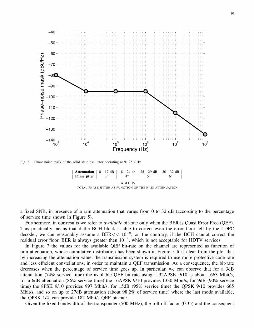
To calculate σφ we considered the phase noise mask given by a commercial Gunn1 oscillator, operatingat 91.25 GHz (Figure 6). Based on the known symbol-rate (fixed to 370 Mbaud/s in our model), on thephase noise mask that we just saw, and on a loop bandwidth that we can reasonably set to 1 MHz, wecan consequently calculate the phase noise jitter, that turns out to be about 2 degrees. We should alsoadd to this jitter the thermal noise contribute, which is mostly influenced by the SNR and by the rainattenuation considered in our model, as shown in Eq. 5:
στ ∼=
√√√√[2EsN0
· Rs
BL
]−1
(5)
where Es/N0 is the SNR computed including the rain attenuation factor. The total phase jitter σTOT cannow be computed as:
σTOT =√σ2φ + σ2
τ (6)
Based on our simulations we obtain the values reported in Table IV: here, as already stated, σTOTmainly depends on SNR and, therefore, on rain attenuation.
VI. RESULTS AND SCENARIOS
As explained in the previous sections, the purpose of our simulations is to find for each DVB-S2 mode(that is the combination of modulation and LDPC code-rate) the bit error rate (BER) of the channel, given
1provided by Rheinmetall Italia S.p.A.[4]
10
103 104 105 106 107 108−140
−130
−120
−110
−100
−90
−80
−70
−60
−50
−40
Frequency (Hz)
Phas
e−no
ise
mas
k (d
Bc/H
z)
Fig. 6. Phase noise mask of the solid state oscillator operating at 91.25 GHz
Attenuation 0 - 17 dB 18 - 24 db 25 - 29 dB 30 - 32 dBPhase jitter 3◦ 4◦ 5◦ 6◦
TABLE IVTOTAL PHASE JITTER AS FUNCTION OF THE RAIN ATTENUATION
a fixed SNR, in presence of a rain attenuation that varies from 0 to 32 dB (according to the percentageof service time shown in Figure 5).
Furthermore, in our results we refer to available bit-rate only when the BER is Quasi Error Free (QEF).This practically means that if the BCH block is able to correct even the error floor left by the LDPCdecoder, we can reasonably assume a BER<< 10−8; on the contrary, if the BCH cannot correct theresidual error floor, BER is always greater then 10−6, which is not acceptable for HDTV services.
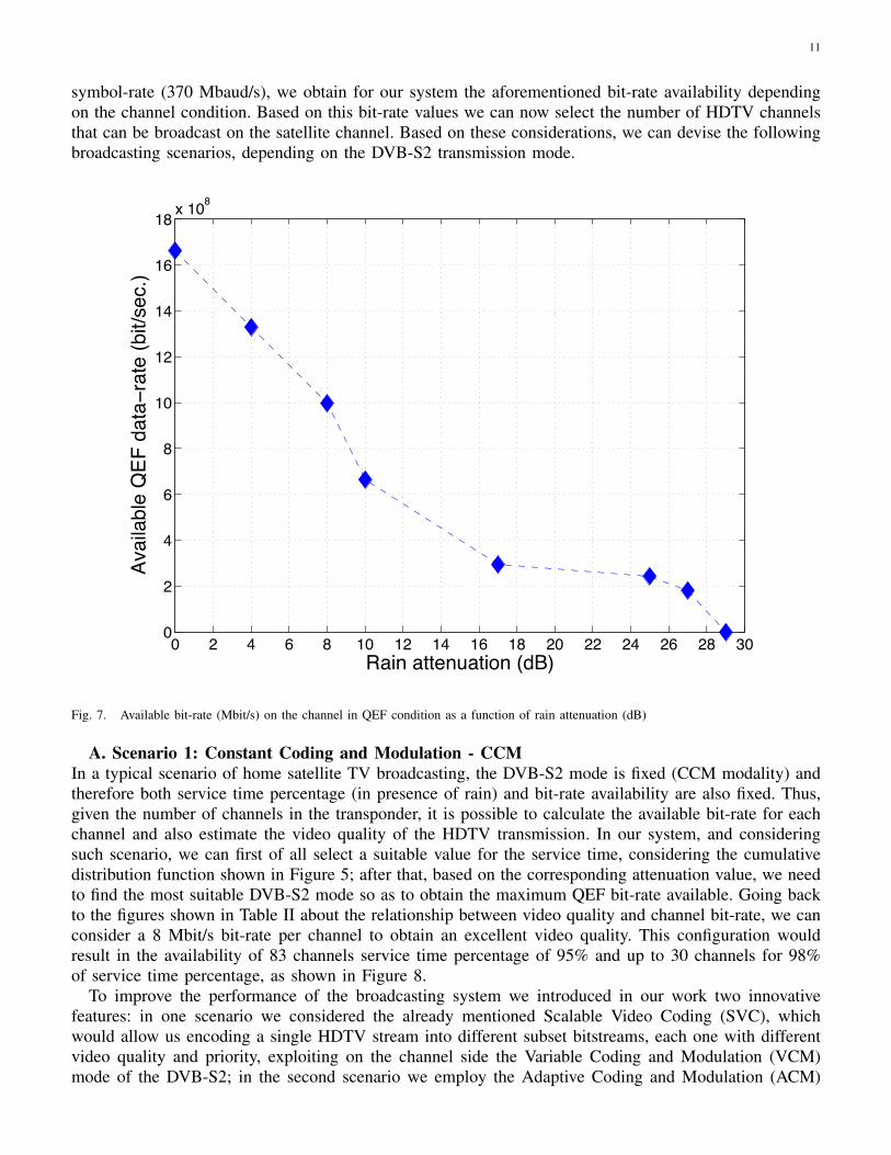
In Figure 7 the values for the available QEF bit-rate on the channel are represented as function ofrain attenuation, whose cumulative distribution has been shown in Figure 5 It is clear from the plot thatby increasing the attenuation value, the transmission system is required to use more protective code-rateand less efficient constellations, in order to maintain a QEF transmission. As a consequence, the bit-ratedecreases when the percentage of service time goes up. In particular, we can observe that for a 3dBattenuation (74% service time) the available QEF bit-rate using a 32APSK 9/10 is about 1663 Mbit/s,for a 6dB attenuation (86% service time) the 16APSK 9/10 provides 1330 Mbit/s, for 9dB (90% servicetime) the 8PSK 9/10 provides 997 Mbit/s, for 15dB (95% service time) the QPSK 9/10 provides 665Mbit/s, and so on up to 27dB attenuation (about 98.2% of service time) where the last mode available,the QPSK 1/4, can provide 182 Mbit/s QEF bit-rate.
Given the fixed bandwidth of the transponder (500 MHz), the roll-off factor (0.35) and the consequent
11
symbol-rate (370 Mbaud/s), we obtain for our system the aforementioned bit-rate availability dependingon the channel condition. Based on this bit-rate values we can now select the number of HDTV channelsthat can be broadcast on the satellite channel. Based on these considerations, we can devise the followingbroadcasting scenarios, depending on the DVB-S2 transmission mode.
0 2 4 6 8 10 12 14 16 18 20 22 24 26 28 300
2
4
6
8
10
12
14
16
18x 108
Rain attenuation (dB)
Avai
labl
e Q
EF d
ata−
rate
(bit/
sec.
)
Fig. 7. Available bit-rate (Mbit/s) on the channel in QEF condition as a function of rain attenuation (dB)
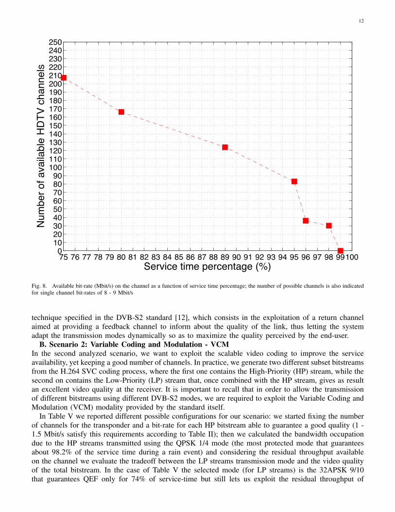
A. Scenario 1: Constant Coding and Modulation - CCMIn a typical scenario of home satellite TV broadcasting, the DVB-S2 mode is fixed (CCM modality) andtherefore both service time percentage (in presence of rain) and bit-rate availability are also fixed. Thus,given the number of channels in the transponder, it is possible to calculate the available bit-rate for eachchannel and also estimate the video quality of the HDTV transmission. In our system, and consideringsuch scenario, we can first of all select a suitable value for the service time, considering the cumulativedistribution function shown in Figure 5; after that, based on the corresponding attenuation value, we needto find the most suitable DVB-S2 mode so as to obtain the maximum QEF bit-rate available. Going backto the figures shown in Table II about the relationship between video quality and channel bit-rate, we canconsider a 8 Mbit/s bit-rate per channel to obtain an excellent video quality. This configuration wouldresult in the availability of 83 channels service time percentage of 95% and up to 30 channels for 98%of service time percentage, as shown in Figure 8.
To improve the performance of the broadcasting system we introduced in our work two innovativefeatures: in one scenario we considered the already mentioned Scalable Video Coding (SVC), whichwould allow us encoding a single HDTV stream into different subset bitstreams, each one with differentvideo quality and priority, exploiting on the channel side the Variable Coding and Modulation (VCM)mode of the DVB-S2; in the second scenario we employ the Adaptive Coding and Modulation (ACM)
12
75 76 77 78 79 80 81 82 83 84 85 86 87 88 89 90 91 92 93 94 95 96 97 98 991000
102030405060708090
100110120130140150160170180190200210220230240250
Service time percentage (%)
Num
ber o
f ava
ilabl
e H
DTV
cha
nnel
s
Fig. 8. Available bit-rate (Mbit/s) on the channel as a function of service time percentage; the number of possible channels is also indicatedfor single channel bit-rates of 8 - 9 Mbit/s
technique specified in the DVB-S2 standard [12], which consists in the exploitation of a return channelaimed at providing a feedback channel to inform about the quality of the link, thus letting the systemadapt the transmission modes dynamically so as to maximize the quality perceived by the end-user.
B. Scenario 2: Variable Coding and Modulation - VCMIn the second analyzed scenario, we want to exploit the scalable video coding to improve the serviceavailability, yet keeping a good number of channels. In practice, we generate two different subset bitstreamsfrom the H.264 SVC coding process, where the first one contains the High-Priority (HP) stream, while thesecond on contains the Low-Priority (LP) stream that, once combined with the HP stream, gives as resultan excellent video quality at the receiver. It is important to recall that in order to allow the transmissionof different bitstreams using different DVB-S2 modes, we are required to exploit the Variable Coding andModulation (VCM) modality provided by the standard itself.
In Table V we reported different possible configurations for our scenario: we started fixing the numberof channels for the transponder and a bit-rate for each HP bitstream able to guarantee a good quality (1 -1.5 Mbit/s satisfy this requirements according to Table II); then we calculated the bandwidth occupationdue to the HP streams transmitted using the QPSK 1/4 mode (the most protected mode that guaranteesabout 98.2% of the service time during a rain event) and considering the residual throughput availableon the channel we evaluate the tradeoff between the LP streams transmission mode and the video qualityof the total bitstream. In the case of Table V the selected mode (for LP streams) is the 32APSK 9/10that guarantees QEF only for 74% of service-time but still lets us exploit the residual throughput of
13
Channels HP stream LP stream Total stream70 1.5 10.088 11.58880 1.5 7.135 8.63590 1 9.370 10.37095 1 8.400 9.400
100 1 7.525 8.525
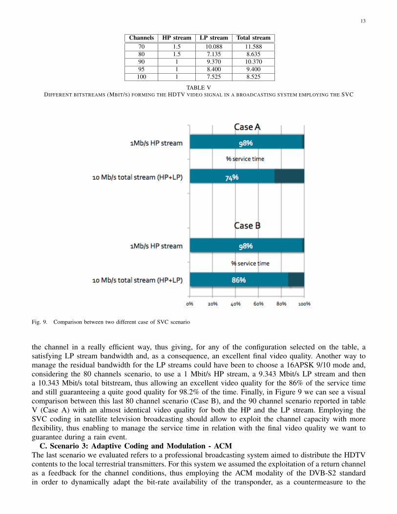
TABLE VDIFFERENT BITSTREAMS (MBIT/S) FORMING THE HDTV VIDEO SIGNAL IN A BROADCASTING SYSTEM EMPLOYING THE SVC
Fig. 9. Comparison between two different case of SVC scenario
the channel in a really efficient way, thus giving, for any of the configuration selected on the table, asatisfying LP stream bandwidth and, as a consequence, an excellent final video quality. Another way tomanage the residual bandwidth for the LP streams could have been to choose a 16APSK 9/10 mode and,considering the 80 channels scenario, to use a 1 Mbit/s HP stream, a 9.343 Mbit/s LP stream and thena 10.343 Mbit/s total bitstream, thus allowing an excellent video quality for the 86% of the service timeand still guaranteeing a quite good quality for 98.2% of the time. Finally, in Figure 9 we can see a visualcomparison between this last 80 channel scenario (Case B), and the 90 channel scenario reported in tableV (Case A) with an almost identical video quality for both the HP and the LP stream. Employing theSVC coding in satellite television broadcasting should allow to exploit the channel capacity with moreflexibility, thus enabling to manage the service time in relation with the final video quality we want toguarantee during a rain event.
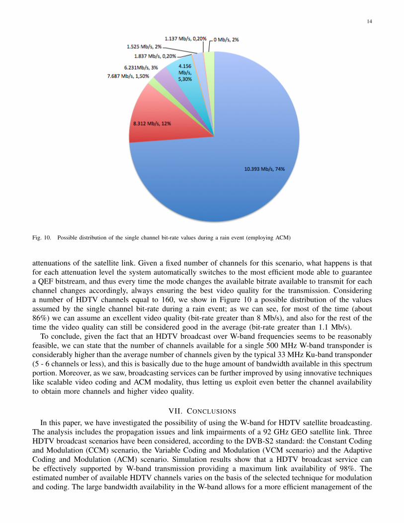
C. Scenario 3: Adaptive Coding and Modulation - ACMThe last scenario we evaluated refers to a professional broadcasting system aimed to distribute the HDTVcontents to the local terrestrial transmitters. For this system we assumed the exploitation of a return channelas a feedback for the channel conditions, thus employing the ACM modality of the DVB-S2 standardin order to dynamically adapt the bit-rate availability of the transponder, as a countermeasure to the
14
Fig. 10. Possible distribution of the single channel bit-rate values during a rain event (employing ACM)
attenuations of the satellite link. Given a fixed number of channels for this scenario, what happens is thatfor each attenuation level the system automatically switches to the most efficient mode able to guaranteea QEF bitstream, and thus every time the mode changes the available bitrate available to transmit for eachchannel changes accordingly, always ensuring the best video quality for the transmission. Consideringa number of HDTV channels equal to 160, we show in Figure 10 a possible distribution of the valuesassumed by the single channel bit-rate during a rain event; as we can see, for most of the time (about86%) we can assume an excellent video quality (bit-rate greater than 8 Mb/s), and also for the rest of thetime the video quality can still be considered good in the average (bit-rate greater than 1.1 Mb/s).
To conclude, given the fact that an HDTV broadcast over W-band frequencies seems to be reasonablyfeasible, we can state that the number of channels available for a single 500 MHz W-band transponder isconsiderably higher than the average number of channels given by the typical 33 MHz Ku-band transponder(5 - 6 channels or less), and this is basically due to the huge amount of bandwidth available in this spectrumportion. Moreover, as we saw, broadcasting services can be further improved by using innovative techniqueslike scalable video coding and ACM modality, thus letting us exploit even better the channel availabilityto obtain more channels and higher video quality.
VII. CONCLUSIONS
In this paper, we have investigated the possibility of using the W-band for HDTV satellite broadcasting.The analysis includes the propagation issues and link impairments of a 92 GHz GEO satellite link. ThreeHDTV broadcast scenarios have been considered, according to the DVB-S2 standard: the Constant Codingand Modulation (CCM) scenario, the Variable Coding and Modulation (VCM scenario) and the AdaptiveCoding and Modulation (ACM) scenario. Simulation results show that a HDTV broadcast service canbe effectively supported by W-band transmission providing a maximum link availability of 98%. Theestimated number of available HDTV channels varies on the basis of the selected technique for modulationand coding. The large bandwidth availability in the W-band allows for a more efficient management of the
15
tradeoff between spectral efficiency and video quality so as to exploit in an optimized way the flexibilityof DVB-S2, in particular when the ACM scenario is considered.
REFERENCES
[1] M. Cominetti, V. Mignone, A. Morello, and M. Visintin, “The European system for digital multi-programme television by satellite,”IEEE Transactions on Broadcasting, vol. 41, no. 2, pp. 49–62, 2002.
[2] E. Matricciani, “Diurnal distribution of rain attenuation in communication and broadcasting satellite systems at 11.6 GHz in Italy,”IEEE Transactions on Broadcasting, vol. 44, no. 2, pp. 250–258, 2002.
[3] V. Mignone, M. Vazquez-Castro, and T. Stockhammer, “The future of satellite tv: The wide range of applications of the dvb-s2 standardand perspectives,” Proceedings of the IEEE, no. 99, pp. 1–17, 2011.
[4] E. Cianca, T. Rossi, A. Yahalom, Y. Pinhasi, J. Farserotu, and C. Sacchi, “Ehf for satellite communications: The new broadbandfrontier,” Proceedings of the IEEE, no. 99, pp. 1–24, 2011.
[5] R. Crane, “Propagation phenomena affecting satellite communication systems operating in the centimeter and millimeter wavelengthbands,” Proceedings of the IEEE, vol. 59, no. 2, pp. 173–188, 2005.
[6] L. Ippolito, “Radio propagation for space communications systems,” Proceedings of the IEEE, vol. 69, no. 6, pp. 697–727, 2005.[7] Y. Pinhasi, A. Yahalom, O. Harpaz, and G. Vilner, “Study of ultrawide-band transmission in the extremely high frequency (EHF) band,”
IEEE Transactions on Antennas and Propagation, vol. 52, no. 11, pp. 2833–2842, 2004.[8] S. Mukherjee, M. De Sanctis, T. Rossi, E. Cianca, M. Ruggieri, and R. Prasad, “On the optimization of DVB-S2 links in EHF bands,”
in 2010 IEEE Aerospace Conference, Big Sky, MT, USA, 2010, pp. 1–11.[9] A. Morello and V. Mignone, “DVB-S2–Ready for lift off,” EBU Technical Review, vol. 10, 2004.
[10] SES-ASTRA, “ASTRA 1H,” http://www.ses-astra.com, Last checked 28/08/2010.[11] C. Sacchi, T. Rossi, M. Ruggieri, and F. Granelli, “Efficient Waveform Design for High-Bit-Rate W-band Satellite Transmissions,” in
IEEE Transactions on Aerospace and Electronic Systems, April 2011 (in press).[12] ETSI EN, “302 307 V1. 2.1 (2009–08): Digital Video Broadcasting (DVB): Second generation framing structure, channel coding and
modulation system for Broadcasting,” Interactive Services, News Gathering and other broadband satellite applications, 2009.[13] A. Saleh, “Frequency-independent and frequency-dependent nonlinear models of TWT amplifiers,” IEEE Transactions on Communi-
cations, vol. 29, pp. 1715–1720, 1981.[14] T. Wiegand, G. Sullivan, G. Bjontegaard, and A. Luthra, “Overview of the H.264/AVC video coding standard,” IEEE Transactions on
Circuits and Systems for Video Technology, vol. 13, no. 7, pp. 560–576, 2003.[15] VideoLAN Project, “x264 - A free H.264/AVC encoder,” http://www.videolan.org/developers/x264.html, Last checked 28/09/2010.[16] Z. Wang, A. Bovik, H. Sheikh, and E. Simoncelli, “Image quality assessment: From error visibility to structural similarity,” IEEE
Transactions on Image Processing, vol. 13, no. 4, pp. 600–612, 2004.[17] T. Zinner, O. Hohlfeld, O. Abboud, and T. Hossfeld, “Impact of frame rate and resolution on objective qoe metrics,” in Quality of
Multimedia Experience (QoMEX), 2010 Second International Workshop on. IEEE, 2010, pp. 29–34.[18] H. Schwarz, D. Marpe, and T. Wiegand, “Overview of the scalable video coding extension of the H.264/AVC standard,” IEEE
Transactions on Circuits and Systems for Video Technology, vol. 17, no. 9, pp. 1103–1120, 2007.[19] D. Taggart and R. Kumar, “Impact of phase noise on the performance of the qpsk modulated signal,” in Aerospace Conference, 2011
IEEE. IEEE, 2011, pp. 1–10.
Nicola Conci is Assistant Professor at the Faculty of Engineering, University of Trento (Italy). He received the Ph.Dfrom the University of Trento in 2007 with a thesis on multiple description video coding. In 2008 and 2009 he waspostdoctoral researcher at Queen Mary, University of London, while in 2007 he was visiting researcher at Universityof California, Santa Barbara. His research interests are in the area of video processing and computer vision for activitydetection and behavioral understanding in video surveillance applications, as well as eye tracking for human machineinteraction. Dr. Conci has been awarded the best student paper award at ACM Mobimedia 2006. He serves as reviewerfor IEEE Trans. on Multimedia, IEEE Trans. on CSVT, as well as for the major IEEE conferences in the area ofvideo analysis and processing. He is affiliate member of the IEEE MMSP and IVMSP technical committees. He’salso currently involved in several projects in the area of video surveillance for the development of assisted living
technologies and rehabilitation tools based on computer vision algorithms.
16
Tommaso Rossi received the “Laurea” Degree in Telecommunications in 2002, MSc Degree in “Advanced Com-munications and Navigation Satellite Systems” in 2004 and Ph.D in Telecommunications and Microelectronics in2008 at the University of Rome “Tor Vergata” where he is currently an Assistant Professor. He is a member of theItalian Space Agency WAVE (W-band Analysis and VErification) Project Technical Team, a feasibility study for W-band telecommunication payloads. He is part of the team that is defining scientific experiments of TDP#5 payloadembarked on ESA Alphabus satellite. His research activity is focused on Space Systems, EHF Satellite and TerrestrialTelecommunications, Satellite and Inertial Navigation Systems, Digital Signal Processing and Satellite Constellations.
Claudio Sacchi received the “Laurea” Degree in Electronic Engineering, and the Ph.D. in Space Science and Engi-neering at the University of Genoa (Italy) in 1992 and 2003, respectively. Since August 2002, Dr. Sacchi has beenholding a position as Assistant Professor at the Faculty of Engineering of the University of Trento (Italy). ClaudioSacchi is author and co-author of more than 70 papers published in international journals and conferences. The researchinterests of Dr. Sacchi are mainly focused on: wideband mobile and satellite transmission systems based on space,time and frequency diversity, MIMO systems, array processing, multi-rate and multi-access wireless communications(OFDMA, DS/CDMA, and MC-CDMA), cross-layer PHY-MAC design, EHF broadband aerospace communications,software defined radio-based design of reconfigurable multi-standard terminals, wireless and satellite communicationsfor emergency recovery applications, etc. Claudio Sacchi is senior member of IEEE and member of IEEE ComSoc
and IEEE AESS Society.