heat transfer and second law analyses of forced convection in a … · 2016-10-13 · 1 heat...
TRANSCRIPT

1
Heat transfer and second law analyses of forced convection in a channel partially filled by
porous media and featuring internal heat sources
Mohsen Torabi*, a, Nader Karimi b, Kaili Zhang a
a Department of Mechanical and Biomedical Engineering, City University of Hong Kong, 83 Tat Chee Avenue,
Kowloon, Hong Kong b School of Engineering, University of Glasgow, Glasgow G12 8QQ, United Kingdom
Abstract
This paper provides a comprehensive study on the heat transfer and entropy generation rates in a channel partially
filled with a porous medium and under constant wall heat flux. The porous inserts are attached to the walls of the
channel and the system features internal heat sources due to exothermic or endothermic physical or physicochemical
processes. Darcy-Brinkman model is used for modelling the transport of momentum and an analytical study on the
basis of local thermal non-equilibrium (LTNE) condition is conducted. Further analysis through considering the
simplifying, local thermal equilibrium (LTE) model is also presented. Analytical solutions are, first, developed for
the velocity and temperature fields. These are subsequently incorporated into the fundamental equations of entropy
generation and both local and total entropy generation rates are investigated for a number of cases. It is argued that,
comparing with LTE, the LTNE approach yields more accurate results on the temperature distribution within the
system and therefore reveals more realistic Nusselt number and entropy generation rates. In keeping with the
previous investigations, bifurcation phenomena are observed in the temperature field and rates of entropy
generation. It is, further, demonstrated that partial filling of the channel leads to a substantial reduction of the total
entropy generation. The results also show that the exothermicity or endothermicity characteristics of the system have
significant impacts on the temperature fields, Nusselt number and entropy generation rates.
Keywords: Entropy generation; Internal heat sources; Forced convection; Local thermal non-equilibrium;
Mathematical modelling
* Corresponding author. E-mails: [email protected] (M. Torabi), [email protected] (N. Karimi).

2
Nomenclature
sfa
interfacial area per unit volume of porous media, 1m− wT lower wall temperature, K
Be Average Bejan number 1fU dimensionless velocity of the fluid in the clear region
Bi Biot number defined in Eq. (13) 2fU dimensionless velocity of the fluid in the porous medium
Br Brinkman number defined in Eq. (13) mU dimensionless mean velocity of the fluid defined in Eq. (17)
pc specific heat at constant pressure, -1 -1J Kg K⋅ ⋅ 1fu velocity of the fluid in the porous medium, -1m s⋅
Da Darcy defined in Eq. (13) 2fu velocity of the fluid in the clear region, -1m s⋅
h one half of the channel height, m mu mean velocity of the fluid, -1m s⋅
ch one half of the thickness of the clear section, m fw
dimensionless energy source in fluid phase per unit volume, -3W m⋅
sfh fluid-to-solid heat transfer coefficient,
-2 -1W m K⋅ ⋅ sw dimensionless energy source in solid phase per unit volume,
-3W m⋅
k ratio of effective solid thermal conductivity to that of fluid X dimensionless axial distance
efk effective thermal conductivity of the fluid ( )fkε ,
-1 -1W m K⋅ ⋅
x axial distance, m
esk
effective thermal conductivity of the solid
( )( )1 skε− , -1 -1W m K⋅ ⋅
Y dimensionless vertical distance
1fN ′′′ dimensionless local entropy generation rate within the clear fluid region defined in Eq. (26) cY
dimensionless one half of the thickness of the clear section
2fN ′′′ dimensionless local entropy generation rate within the fluid phase of the porous medium defined in Eq. (26)
y vertical distance, m
sN ′′′ dimensionless local entropy generation rate within the solid phase of the porous medium defined in Eq. (26)
Greek symbols
tN dimensionless total entropy generation rate within the medium defined in Eq. (27)
ε porosity
Nu Nusselt number defined in Eq. (9) γ ratio of the heat flux at porous-fluid interface to that of channel’s wall
Pe Peclet number defined in Eq. (13) κ permeability, 2m
1fS ′′′ local entropy generation rate within the clear fluid
region, -3 -1W m K⋅ ⋅ fµ
fluid viscosity, -1 -1Kg m s⋅ ⋅
2fS ′′′ local entropy generation rate within the fluid phase of
the porous medium, -3 -1W m K⋅ ⋅ effµ
effective viscosity of porous medium,
-1 -1Kg m s⋅ ⋅
sS ′′′ local entropy generation rate within the solid phase of
the porous medium, -3 -1W m K⋅ ⋅
θ
dimensionless temperature defined in Eq. (13)
fs energy source in fluid phase per unit volume,
-3W m⋅ 1fθ dimensionless temperature of the fluid within clear region
ss energy source in solid phase per unit volume,
-3W m⋅ 2fθ
dimensionless temperature of the fluid phase of the porous medium
T temperature, K ,f mθ dimensionless mean temperature of the fluid defined in Eq. (22)
1fT temperature of the fluid within clear region, K sθ dimensionless temperature of the solid phase of the porous medium
2fT temperature of the fluid phase of the porous medium,
K

3
,f mT mean temperature of fluid, K ρ fluid density, -3Kg m⋅
sT temperature of the solid phase of the porous medium,
K
1. Introduction
Energy challenges are currently amongst the most substantial issues facing the human civilisation. The rapid
increases in energy consumption along with the subsequent catastrophic environmental problems have led to a
complex global crisis. A range of activities are being undertaken to resolve this issue across the world. These,
chiefly, include more extensive use of renewable energy and improving the efficiency of the conventional energy
generation technologies. Both of these two families of technology heavily involve thermal processes. Optimisation
of these processes is essential for improving the performance of a wide range of energy generation technologies.
Similarly, optimal thermal systems are central to the efficient use of thermal energy.
In principle, there are two approaches to the problem of thermal optimisation. In the most conventional approach,
the system is analysed on the basis of an energy balance or first law of thermodynamics. This approach is well
known and has been in use for a long time. Despite all its practical merits, this remains an entirely quantitative
method and provides no information on the quality of energy. Importantly, the degradation of energy due to the
existence of irreversibilities is totally ignored by this approach [1–3]. These negative points have led the researchers
to consider an alternative approach for optimisation of a thermal process by considering both of the first and second
laws of thermodynamics. The second law of thermodynamics provides a powerful tool to evaluate the energy quality
degradation in a thermal system while the first law governs the energy balance. This method constructs fundamental
relations to calculate the generation of entropy within a system and accordingly realises the level of irreversibility. It
has been pointed out, in the literature, that through using this method the system can be optimised from the energy
quality prospect through minimisation of the entropy generation. This has been elaborated in details by Bejan in his
seminal textbooks [2,3]. Shifting from the energy quantity point of view to an energy quality perspective in a
thermal process reveals the advantage of the second law of thermodynamics over the first law. By employing the
former it is possible to optimise the process such that less entropy is generated, and consequently less exergy is
destructed. In other words, the energy quality remains as high as possible. This concept has been, already, exploited
in various conductive [4–6], convective [7–9] and radiative [10] environments.
Channels under forced convection are an important part of various thermal systems [11]. Recently, heat transfer and
entropy generation analyses in horizontal channels, fully or partially filled with porous media, have attracted
considerable attention [11]. This is, primarily, due to the fact that utilising porous media can lead to significant
improvements in heat transfer characteristics [12]. Energy analysis in porous media is usually on the basis of a
fundamental assumption about the presence or absence of local thermal equilibrium [11,12]. The former leads to
local thermal equilibrium (LTE) model, also known as one-equation energy model. The latter, however, is regarded
as local thermal non-equilibrium (LTNE), or two-energy equation model [11,12]. Although LTE model [11] has
been used extensively in heat transfer analyses [11], LTNE model is receiving an increasing attention from the
research community [13–16]. This stems from the fact that in the emerging fields such as MEMS and biotechnology

4
as well as some classical areas, such as chemical and nuclear engineering, the accuracy of the analysis is of primary
importance [12,17]. Hence, LTNE modelling becomes the preferred option. This, however, significantly increases
the mathematical complexity of the analysis and therefore the choice of thermal model should be made mindfully.
There have been a large number of publications on convective heat transfer in porous media under LTNE
conditions. One of the pioneering works in this area was done by Nield [13]. Following Nield’s persuasive work,
many scholars have tried to re-examine thermal porous systems from the LTNE perspective [18–26]. Bortolozzi and
Deiber [19] investigated natural convection in a fluid-saturated annular porous cavity considering both LTE and
LTNE conditions. The governing equations were numerically solved using vorticity-stream function scheme.
Comprehensive comparison was made between the velocity and temperature fields for both models and considerable
differences were observed in some cases [19]. In a fundamental study Kim and Jang [20] validated their similarity
solution for convection in porous media against a numerical solution within the framework of LTNE. They also
compared the results of LTNE with those of LTE model [20]. Similar to an earlier work of Bortolozzi and Deiber
[19], Kim and Jang [20] observed that for some certain thermophysical parameters the difference between LTE and
LTNE models is non-negligible. Khashan et al. [21] revisited the classical problem of steady state fluid flow and
heat transfer in a porous pipe using SIMPLE algorithm under LTNE model. Influences of Reynolds and Biot
numbers on the temperature contours and other thermal characteristics of the system were investigated in this work
[21]. Chen and Tso [22] used LTNE model in a channel fully filled with porous media. They incorporated viscous
dissipation effects into the energy equation for the fluid phase of the porous medium and numerically investigated
the variation of Nusselt number with a number of thermophysical parameters. In a separate study, these authors
developed analytical expressions for Nusselt number [23]. Ouyang et al. [24] used three different fundamental
LTNE models in a channel. The analytical solutions for the flow and temperature fields were obtained and compared
with those predicted by numerical simulations. Through using the classical definition of the thermal entry length on
the basis of Nusselt number, the dimensionless thermal entry length was predicted [24]. Dehghan et al. [25,26]
considered both Darcy and Forchheimer terms in the momentum equation but neglected the viscous dissipation in
the energy equation. Perturbation technique was employed by these authors to tackle the resultant nonlinear
governing equations [25,26] and semi-analytical solutions for the temperature and Nusselt number were derived.
Comparisons were, further, made with the previously published works and good agreements were observed [25,26].
Ochoa-Tapia and Whitaker [27] were, perhaps, the first scholars who considered a flow conduit partially filled with
porous media. Partial filling is an effective avenue to circumvent significant pressure drops in a porous system [28].
By adopting this approach the desirable thermal effects of a porous medium can be mostly achieved. Yet, the
pumping power and the consequent expenses are maintained within a reasonable range. These attractive features
have resulted in a significant number of published studies on the thermal aspects of partially filled systems, see for
example [14–16,29]. In the partially filled systems, the thermal boundary condition of the interface of the porous
material and clear fluid poses a fundamental difficulty. A precise explanation of the heat distribution on such
interfaces is yet to be developed [12]. Nonetheless, phenomenological thermal models are often used to provide the
essential mathematical boundary conditions in the modelling works. Yang and Vafai [30,31] provided two different

5
main models for the interface condition together with their analytical solutions. They have discussed the limitations
of each model and gave illustrative figures regarding the variation of Nusselt number in each model. Further
examples of such modelling efforts can be found in Refs. [14,15,29] which used models A and B of Yang and Vafai
[31] for the porous-fluid interface. Model A assumes that the heat flux is divided between the two phases on the
basis of their effective conductivities and temperature gradients. However, in model B equal amounts of heat flux
are transferred into each phase [31].
Xu et al. [32,33] analytically solved the flow field and energy equation for a parallel-plate channel [32] and a pipe
[33] partially filled with porous media attached to the inner wall of each geometry. Convective boundary condition
was considered at the porous-fluid interface. They illustrated the temperature distribution with different
thermophysical parameters and showed that Nusselt number decreases if the channel is fully filled with porous
media. Later, this was also demonstrated by other researchers [34,35]. Yang et al. [36] examined the differences
between the thermal performance of a tube partially filled with a metal foam when it is attached to the inner wall or
placed in the core of the tube. They considered equal temperature for the metal foam and fluid phase at the porous-
fluid interface and developed analytical solutions for the temperature fields and Nusselt number [36].
The studies, discussed so far, were solely concerned with heat transfer aspects of the problem and therefore belong
to the first law approach. As argued earlier, the first law of thermodynamics remains silent on the quality of energy
in a given thermal process and any judgment on this requires a second law investigation. A partially filled flow
conduit with significant heat transfer involves major sources of irreversibility. These include heat transfer through a
finite temperature difference and viscous dissipation of the flow kinetic energy. It is, therefore, expected that the
system involves a non-negligible level of entropy generation and experiences a drop of energy quality. As the
irreversibility is partially due to non-equilibrium heat transfer, taking LTNE approach is essential in the evaluation
of the second low performance of the process. However, there is, currently, a dearth of thermodynamic analyses of
partially or fully filled systems under LTNE condition and most of the existing works in this area are limited to local
thermal equilibrium [37–40]. Recently, Buonomo et al. [41] have conducted a study on porous filled micro channel
by using LTNE model. They investigated the hydrodynamic and thermal processes between two parallel plates filled
with a porous medium [41]. Due to the microscale size of the channel and effects of rarefaction of the gas flow
under consideration, the first order velocity slip and temperature jump conditions at the fluid-solid interface were
used. In this work, the velocity and temperature fields were analytically investigated, and local and total entropy
generation rates were calculated [41]. Most recently, Torabi et al. [42] utilised LTNE model and analysed heat
transfer and entropy generation in a horizontal channel partially filled with porous media. They considered
asymmetric boundary conditions for the channel and incorporated the viscous dissipation term into the energy
equations. For the first time, these authors reported a bifurcation phenomenon for the local entropy generation rate
[42].
The current work conducts a comprehensive study on the heat transfer and entropy generation in a channel under
forced convection, which is partially filled with a porous medium. Both LTE and LTNE models are applied and the
outcomes are compared. The channel is under constant and equal heat fluxes from both top and bottom surfaces. The

6
Darcy-Brinkman model is used to model the transport of momentum and internal heat generation or consumption is
incorporated into the energy equation. These internal sources represent the exothermic or endothermic physical and
chemical reactions occurring in various practical processes [29,43,44]. The rest of this paper has been organised in
the following order. Section 2 gives the detailed specifications of the problem. In this section, the governing
equations of heat and fluid flow together with the boundary conditions for the employed interface models are
described. Section 3 provides the fundamental equations of entropy generation in the configuration under
investigation. By introducing dimensionless boundary conditions, the available local and total entropy generation
relations are non-dimensionalised. Subsequently, in section 4 the momentum and energy equations are solved
analytically. Through incorporating the velocity and temperature solutions within the entropy generation relations,
given in Section 3, the local and total entropy generation rates are calculated. Section 5 includes a series of figures
regarding temperature, Nusselt number and, local and total entropy generation rates. This section further provides a
comprehensive discussion on the effects of pertinent parameters on the temperature and entropy generation. The
paper is finally concluded in Section 6.
2. Problem statement
Consider a rectangular, two dimensional channel subjected to uniform and equal heat fluxes on the upper and lower
surfaces. The channel is partially filled with a porous medium such that the porous material is attached to the upper
and lower walls, as shown in Fig. 1. The height of the channel is 2h and the core of the channel, with the thickness
2 ch , is clear. Constant thermophysical properties for both solid and fluid phases are assumed. This study, further,
assumes steady, laminar flow along with fully developed velocity and temperature fields and ignores radiative heat
transfer and gravitational effects. Darcy-Brinkman model is utilised to model the transport of momentum within the
porous material, and homogeneous and isotropic characteristics are assumed for the porous structure. In the course
of this study the fluid and solid thermal source terms are assumed to have constant values. Due to the symmetry of
the problem under investigation only half of the configuration shown in Fig. 1 is considered.
2.1. Governing equations
Considering the aforementioned assumptions and the configuration shown in Fig. 1, the momentum and energy
equations under LTNE model are written as follows. Momentum equations in the clear and porous regions are
expressed by
21
20 0f
f c
upy h
x yµ
∂∂− + = ≤ ≤∂ ∂
, (1a)
22
220f f
eff f c
upu h y h
x y
µµ
κ∂∂
− + − = ≤ <∂ ∂
. (1b)
Transport of thermal energy for the clear region, and fluid and solid phases of the porous region are respectively
written as

7
21 1
1 20f f
p f f f c
T Tc u k s y h
x yρ
∂ ∂= + ≤ ≤
∂ ∂, (2a)
( )2
2 22 22
f fp f ef sf sf s f f c
T Tc u k h a T T s h y h
x yρ
∂ ∂= + − + ≤ <
∂ ∂, (2b)
( )2
220 s
es sf sf s f s c
Tk h a T T s h y h
y
∂= − − + ≤ <
∂, (2c)
where the feff
µµ
ε= is the effective viscosity and different terms and notations are defined in the nomenclature.
The boundary conditions for the above system of equations are
1 10 : 0, 0f fu Ty
y y
∂ ∂= = =
∂ ∂, (3a)
1 2 1 21 2 int 1 2: , , ,sf f f f
c f f f eff f ef es f f s
Tu u T Ty h u u q k k k T T T
y y y y yµ µ
∂∂ ∂ ∂ ∂= = = = = + = =
∂ ∂ ∂ ∂ ∂, (3b)
22 2: 0, , sf
f f s w w ef es
TTy h u T T T q k k
y y
∂∂= = = = = +
∂ ∂. (3c)
The boundary conditions expressed by Eq. (3b) and (3c) are equivalent to model A of Yang and Vafai [31], which
has been also used in the investigations of partially filled channels [16,29]. It is emphasised here that previous works
[14–16] have demonstrated that the choice of porous-fluid boundary condition has significant effects upon the
thermal behaviour of the system.
In order to make analytical progress with the energy equations (2a) and (2b), their left hand sides should be
evaluated. By integrating Eq. (2a) and with the help of boundary conditions at the upper side of the channel and the
interface, the following relation is derived,
int
21 1
1 20 0 0
d d dc c ch h h
f fp f f f
q
T Tc u y k y s y
x yρ
∂ ∂= +
∂ ∂∫ ∫ ∫
. (4)
Adding Eqs. (2b) and (2c), integrating the resultant equation, and incorporating the boundary conditions at the upper
side of the channel and the interface yields

8
( )
int
222 2
2 2 2d d d d
c c c c
w
h h h hsf f
p f ef es f sh h h h
q q
TT Tc u y k y k y s s y
x y yρ
−
∂∂ ∂= + + +
∂ ∂ ∂∫ ∫ ∫ ∫
. (5)
By adding Eqs. (5) and (4) and noting that in a fully-developed flow subjected to constant wall heat flux
2 1 constantf fT T
x x
∂ ∂= =
∂ ∂, the left hand side of Eqs. (2a) and (2b) becomes
01 2
d dc
h h
w f shf f
p pm
q s y s yT T
c cx x hu
ρ ρ+ +∂ ∂
= =∂ ∂
∫ ∫, (6)
where
1 20
1d d
c
c
h h
m f fh
u u y u yh = + ∫ ∫ . (7)
Incorporating Eq. (6) into the Eqs. (2a) and (2b), results in the following energy equations for the fluid flow in the
clear and porous regions,
20 1
1 2
d d0c
h h
w f sh f
f f f cm
q s y s yT
u k s y hhu y
+ + ∂= + ≤ ≤
∂
∫ ∫, (8a)
( )2
0 22 22
d dc
h h
w f sh f
f ef sf sf s f f cm
q s y s yT
u k h a T T s h y hhu y
+ + ∂= + − + ≤ <
∂
∫ ∫. (8b)
The Nusselt number at the lower wall of the channel can be written as [32,33,35,36]
( )1, ,
4 w
f f w f m
h qNu
k T T
×=
−. (9)
where
, 1 1 2 20
1d d
c
c
h h
f m f f f fh
m
T u T y u T yhu
= + ∫ ∫ . (10)
When ratio of the thermal conductivity of the two phases of the porous section is near unity, the LTE model can be
often used [45]. This is due to the fact that as the thermal conductivities of the two phases approach each other and
Biot number is large enough, the temperature difference between the solid and fluid phases in the porous region

9
diminishes. Hence, the energy equations (2b) and (2c) can be combined to form a single energy equation for the
porous region. Considering LTE model, the energy equations for the fluid and porous regions can be written as
21 1
1 20f f
p f f f c
T Tc u k s y h
x yρ
∂ ∂= + ≤ ≤
∂ ∂, (11a)
( )2
2 22 2
f fp f ef es f s c
T Tc u k k s s h y h
x yρ
∂ ∂= + + + ≤ <
∂ ∂. (11b)
It should be noted that as a result of LTE assumption in Eq. (11b), 𝑇𝑓2 = 𝑇𝑠. The thermal boundary conditions for
this model are slightly different to those of LTNE model and are described by the following relations.
10 : 0fTy
y
∂= =
∂, (12a)
( )1 2int 1 2: ,f f
c f ef es f f
T Ty h q k k k T T
y y
∂ ∂= = = + =
∂ ∂, (12b)
( ) 22: , f
f w w ef es
Ty h T T q k k
y
∂= = = +
∂. (12c)
2.2. Normalisation
To provide further physical insight, the following dimensionless variables are introduced. These include a wide
range of thermophysical properties and will be used in the proceeding discussions.
( ) ( ) 2
2
2int
1, , , , , , ,
, , , , ,
es w ses sf sf cc
r w ef f es
p r s ef wf r ff s
w ef w w w w
k T T kk h a h hu y xU k Bi Y X Y Da
u q h k k k h h h h
c u h q s h k Tu s hBr Pe w w B
q h k q q q q h
ε κθε
ρµγ
− −= = = = = = = = =
= = = = = =
(13)
where 2
rf
h pu
xµ∂
= −∂
. Substituting the above parameters into the momentum Eqs. (1a) and (1b), energy equations
(2c), (8a) and (8b), and boundary equations (3), results in the following set of non-dimensional governing equations
and boundary conditions. Momentum Eqs. (1a) and (1b) are converted to
21
21 0 0f
c
UY Y
Y
∂+ = ≤ ≤∂
, (14a)

10
22 2
2
11 0 1f f
c
U UY Y
DaYε∂
+ − = < ≤∂
. (14b)
The dimensionless form of energy Eqs. (2a, b and c) are
21 1
2
10f f
f cm
AUw Y Y
U k Y
θε
∂= + ≤ ≤
∂, (15a)
( )2
2 222
11f f
s f f cm
AUBi w Y Y
U k Y
θθ θ
∂= + − + ≤ ≤
∂, (15b)
( )2
220 1s
s f s cBi w Y YY
θθ θ
∂= − − + ≤ ≤∂
. (15c)
Through non-dimensionalisation, the boundary conditions reduce to the followings
1 10 : 0, 0f fUY
Y Y
θ∂ ∂= = =
∂ ∂, (16a)
1 2 1 21 2 1 2
1 1 1: , , ,sf f f f
c f f f f s
U UY Y U U
Y Y k Y k Y Y
θθ θγ θ θ θ
ε ε∂∂ ∂ ∂ ∂
= = = = = + = =∂ ∂ ∂ ∂ ∂
, (16b)
22 2
11: 0, 1 , 0sf
f f sY Uk Y Y
θθθ θ
∂∂= = = + = =
∂ ∂, (16c)
where
1 1
01 d d
cf s
YA w Y w Y= + +∫ ∫ , (17a)
1
1 20
d dc
c
Y
m f fY
U U Y U Y= +∫ ∫ . (17b)
Further, γ can be readily calculated through Eqs. (5), (4) and the dimensionless parameters (13), from the following
relation
1 1
10 0
0
1 d d dd
c
cc
Y
f s f YY
fm
w Y w Y U Yw Y
Uγ
+ + = −
∫ ∫ ∫∫ . (18)
It is curious to note that the boundary conditions related to the heat flux at the upper wall of the channel and the
adiabatic condition in the middle of the channel ( 0y = ) have been used in the derivation of Eqs. (5) and (4). These

11
will not be used to derive the constant parameters of the energy equations. To decouple the energy equations of the
fluid phase from that of the solid phase, i.e., Eqs. (15b) and (15c), the second derivatives of these equations are
needed. Some straightforward algebraic manipulations turn these two equations into the followings,
2 4 2 22 2 2 2
2 4 2 2
1 11f f f f f
f sm m
U AU wABi w w
U k U kY Y Y Y
θ θ ∂ ∂ ∂ ∂ = + − + − − + ∂ ∂ ∂ ∂ , (19a)
( )4 2 2
24 2 2
0 1s s sff s
m
wkAUBi k kw kw
UY Y Y
θ θ ∂ ∂ ∂= − − + + + + + ∂ ∂ ∂
. (19b)
Now, by using Eqs. (15b) and (15c) and their first derivatives, the following boundary conditions are developed.
These are essential for the closure of the problem and are given by,
2
2
22
2
32 2 2
3
32
3
0
10
1:1
0
ss
ff
sf f f f
m
s s sf
wY
wk Y
YU wA
BiU Y k Y Y YY
wBi
Y Y YY
θ
θ
θθ θ
θ θ θ
∂+ =
∂ ∂
+ =∂= ∂∂ ∂ ∂ ∂ = + − + ∂ ∂ ∂ ∂∂
∂ ∂ ∂∂ − − + = ∂ ∂ ∂∂
(20)
Accordingly, the dimensionless Nusselt number is given by the following relation.
,
4
f m
kNu
εθ
= − , (21)
where
1
, 1 1 2 20
1d d
c
c
Y
f m f f f fY
m
U Y U YU
θ θ θ = + ∫ ∫ . (22)
Considering LTE model and using the dimensionless parameters given by Eq. (13), the dimensionless LTE energy
equations can be written as
21 1
2
10f f
f cm
AUw Y Y
U k Y
θε
∂= + ≤ ≤
∂, (23a)
22 2
2
11 1f f
f s cm
AUw w Y Y
U k Y
θ∂ = + + + ≤ ≤ ∂ . (23b)
12
Once again, it is emphasised that due to LTE in Eq. (23b) 𝜃𝑓2 = 𝜃𝑠. The thermal boundary conditions for LTE
model are slightly different from the thermal boundary condition for LTNE model and are expressed by,
10 : 0fYY
θ∂= =
∂, (24a)
1 21 2
1 1: 1 ,f f
c f fY Yk Y k Y
θ θγ θ θ
ε∂ ∂ = = = + = ∂ ∂
, (24b)
22
11: 1 1 , 0f
fYk Y
θθ
∂ = = + = ∂ . (24c)
3. Entropy generation
It has been intuitively considered in the previous publications that the heat generation implies its effects on the
entropy generation thorough diffusive heat transfer part of the entropy generation formula [46–48]. Moreover, in
many second law analyses for conductive media it has been mathematically proven that the entropy generation
formula does not affected by internal heat generation and this feature of the system input its impact on the
temperature distribution and therefore into the entropy generation. This can be clearly seen in recent publications in
this field [5,6,49]. However, since the energy equations in convective systems are mainly partial differential
equation with many terms, this mathematical endorsement has not been taken previously. In keeping with previous
literature in the field, it has been assumed in this study that the internal heat generation/consumption does not have
direct effect on the entropy generation and implies its effects on the temperature distribution, i.e., on the diffusion
term of entropy formula.
Bearing the abovementioned information in mind, it is assumed in this study that the generation of entropy in the
thermal system under investigation is due to heat transfer over a finite temperature difference and viscous
dissipation of the flow kinetic energy. These mechanisms generate entropy in the solid and fluid phases within the
porous regions and the fluid phase of the clear region. Under LTNE model the following relations hold for the
volumetric rate of the local entropy generation within the fluid phase of the clear region, fluid phase of the porous
medium and solid phase of the porous medium, respectively.
2 22
1 1 11 2
11
0f f f f ff c
ff
k T T uS y h
x y T yT
µ ∂ ∂ ∂ ′′′ = + + ≤ ≤ ∂ ∂ ∂
, (25a)
( )22 222 22 2 2
2 222 2 22
sf sf s fef efff f f ff f c
s f f ff
h a T Tk T T uS u h y h
x y T T T T yT
µµκ
− ∂ ∂ ∂ ′′′ = + + + + ≤ < ∂ ∂ ∂
, (25b)

13
( )2222
22
sf sf s fes s ss c
s fs
h a T Tk T TS h y h
x y T TT
− ∂ ∂ ′′′ = + + ≤ < ∂ ∂
. (25c)
The detailed derivations of these equations can be found in [41,42,46,50], and are not repeated here. Incorporation
of the dimensionless parameters introduced in Eq. (13) into Eqs. (25a, b and c) results in the dimensionless local
volumetric entropy generation rates, which are expressed by
( )
( ) ( )
212
0 0 12
12
11 2
11
1 d d
0
cY
f sf
fm
ff c
es ff
w Y w Y
UPe k U YBr
S h YN Y Y
k Bk B
θ
θε θ
+ + ∂ + ∂∂ ′′′ ∂ ′′′ = = + ≤ ≤++
∫ ∫
,
(26a)
( )
( )( )
( )( ) ( )
( )
212
0 0 2
22 222 2
2 22 22
2
2
2
1 d d
1
cY
f sf
m
s ff ff
es s f ff
f
cf
w Y w Y
Pe k U YBiS h BrU
Nk B B Da Bk B
UBr
YY Y
B
θ
θ θθ θ θθ
ε θ
+ + ∂ + ∂ −′′′ ′′′ = = + +
+ + ++
∂ ∂ + ≤ <
+
∫ ∫
(26b)
( )
( )( )
( )( )
212
0 0
222
22
1 d d
1
cY
f ss
m
s fss c
es s fs
w Y w Y
Pe k U YBiS h
N Y Yk B BB
θ
θ θθ θθ
+ + ∂ + ∂ −′′′ ′′′= = + ≤ <
+ ++
∫ ∫
,
(26c)
where the parameter w es
w
T kB
q h= depends on the thermophysical properties of the channel. It is worth mentioning
that, assuming reference temperature for the denominators of Eqs. (25a, b and c) would decrease the mathematical
complexity of the model and could be used in this work similar to Refs. [51–53]. However, to predict the local and
total entropy generation rates more accurately, the local temperature is used in the denominator of these equations.
This approach has been taken in some recent works [10,54,55]. Accordingly, the dimensionless total entropy
generation rate for the channel is given by integrating the dimensionless form of the volumetric local entropy
generation relations, over the height of the channel. That is
( )1
1 20
d dc
c
Y
t f f sY
N N Y N N Y′′′ ′′′ ′′′= + +∫ ∫ . (27)

14
The average Bejan number, i.e., Be , defined as the ratio between the total entropy generation due to heat transfer
by the total entropy generation [51], is expressed as
h
t
NBe
N= . (28)
when hN which is the entropy generation rate due to heat transfer can be calculated from integration over the
specific boundary for the first terms of Eq. (26a), the first and second terms of Eq. (26b) and both terms of Eq. (26c).
It is worth mentioning here that the heat transfer irreversibility is dominant when Be approaches to 1. When Be is
less than 1 2 and approaches to zero, the irreversibility due to the viscous effects dominates the processes and if
1 2Be = the entropy generation due to the viscous effects and the heat transfer effects are equal [53].
4. Velocity and temperature fields
This section provides analytical solutions for the momentum and energy equations derived in Section 2.2 and
therefore reveals the velocity and temperature fields in the porous and clear regions. Solution of Eqs. (14a) and
(14b) results in the following expressions for the velocity fields within the porous and clear regions,
21 1 2
1
2fU Y C Y C= − + + , (29a)
2 3 4sinh coshf
Y YU C C Da
Da Daε ε
= + +
, (29b)
where the four constant parameters 1 4C C− are obtained from the velocity boundary conditions and expressed by
1 0C = , (30a)
2
2
1 1sinh cosh
2
1cosh
c c cc
c
Y Y YY Da Da Da
Da DaC
Y
Da
ε εε ε
ε
− −− + + − =
−
, (30b)
3
1cosh sinh
1cosh
cc
c
YY Da Da
Da DaC
Y
Da
ε εε ε
ε
− +
= −
, (30c)

15
4
1sinh cosh
1cosh
cc
c
YY Da Da
Da DaC
Y
Da
ε εε ε
ε
−
= −
. (30d)
16
Solutions of the differential energy equations, Eqs. (19a) and (19b), provide the general temperature distributions within the porous regions and under LTNE model. Further,
solving Eq. (15a) renders the temperature field in the clear region. These temperature fields are
4 3 2 21 2
1 1 2
1 11 12 32
m f
fm
k AY AC Y AC Y U w YDY D
U
εθ
− + + − = + + , (31a)
( )( ) ( )22
3 1 4 1 232 42 5 6
1 1 1 1
cosh sinh1cosh sinh
2f
D kA Y D kA YA kDaA kDa AY YY D Y D
A kDa kA kA ADa Daθ
ε ε εε ε
− − − = + + + − + + + , (31b)
( ) ( ) ( )2
27 8 42 3 1 1 9 10
1 1 1 1
cosh sinh cosh sinh2s
D D BDa Y YB B A Y A Y Y D Y D
B Da B B BDa Daθ
ε ε ε ε
− = + − − + − − + + + , (31c)
where
( )3 34 41 2 3 4, , , f s
m m m m m
BiAC A CBiAC A C BiADaA Bi Bi k A A A Bi w w
U DaU U DaU U
εε= − − = − = − = − + , (32a)
( )341 2 3 4, , , f s
m m m
BikACBikAC BikADaB Bi Bi k B B B Bik w w
U U U= − − = = = − + .
(32b)

17
The ten unknown parameters 1 10D D− are obtained numerically using mathematical software Maple. The
correctness of the solution procedure has been verified repeatedly in our previous works [42,56]. The solution for
the temperature distribution with LTE model is straightforward and much simpler than the elaborated procedure
taken for LTNE model and is therefore not reported here.
5. Results and discussion
The calculated velocity, temperature, and local and total entropy generation rates are presented in this section. The
results, further, include ratio of the interface heat flux to the heat flux of the boundary condition, i.e. γ , and Nusselt
number. The current section has been divided into two subsections. In subsection 5.1 the velocity and temperature
fields are presented. Subsection 5.2 provides a discussion on the local and total entropy generation rates which are
pertinent to the second law of thermodynamics. It is noted that the problem under investigation has not been tackled
previously in any theoretical and numerical work. Hence, a direct comparison of the current results with those of
others is not possible. Nonetheless, it was observed that through increasing the Biot number the current solutions of
the temperature fields approached those predicted by LTE analysis. It is well established that in the limit of infinite
Biot number, LTNE and LTE solutions are equivalent. Thus, this observation serves as a validation of the current
results. As a general matter, in all proceeding graphs of temperature and local entropy generation rates, the dash and
solid lines are, respectively, in connection with the fluid and solid phases.
5.1. Velocity, temperature and Nusselt number
Figures 2 and 3 show the velocity distribution within the partially filled porous channel. These figures show that in
keeping with the findings of the previous investigations [32,33,42], thicker porous sections tend to magnify the
maximum velocity in the clear region. Further, a comparison between Figs. 2 and 3 reveals that generally lower
Darcy numbers result in more abrupt changes in the behaviour of the fluid velocity profile around the porous-fluid
interface. This is apparent in these two figures at around 0.3Y = for 0.3cY = . The velocity field changes its
general pattern from the clear region in the lower part of these figures to that within the porous section in the upper
section of the figures. Due to the smoother change of the velocity pattern from the porous section to the clear section
at higher Darcy number (see Fig. 2), the maximum velocity of the clear flow in Fig. 2 is smaller than that in Fig. 3.
This behaviour is, also, due to the fact that by lowering the Darcy number in Fig. 3 a smaller volumetric flow rate
enters the porous region. Hence, the share of the clear region from the total flow increases, which results in a more
significant peak in the flow velocity.
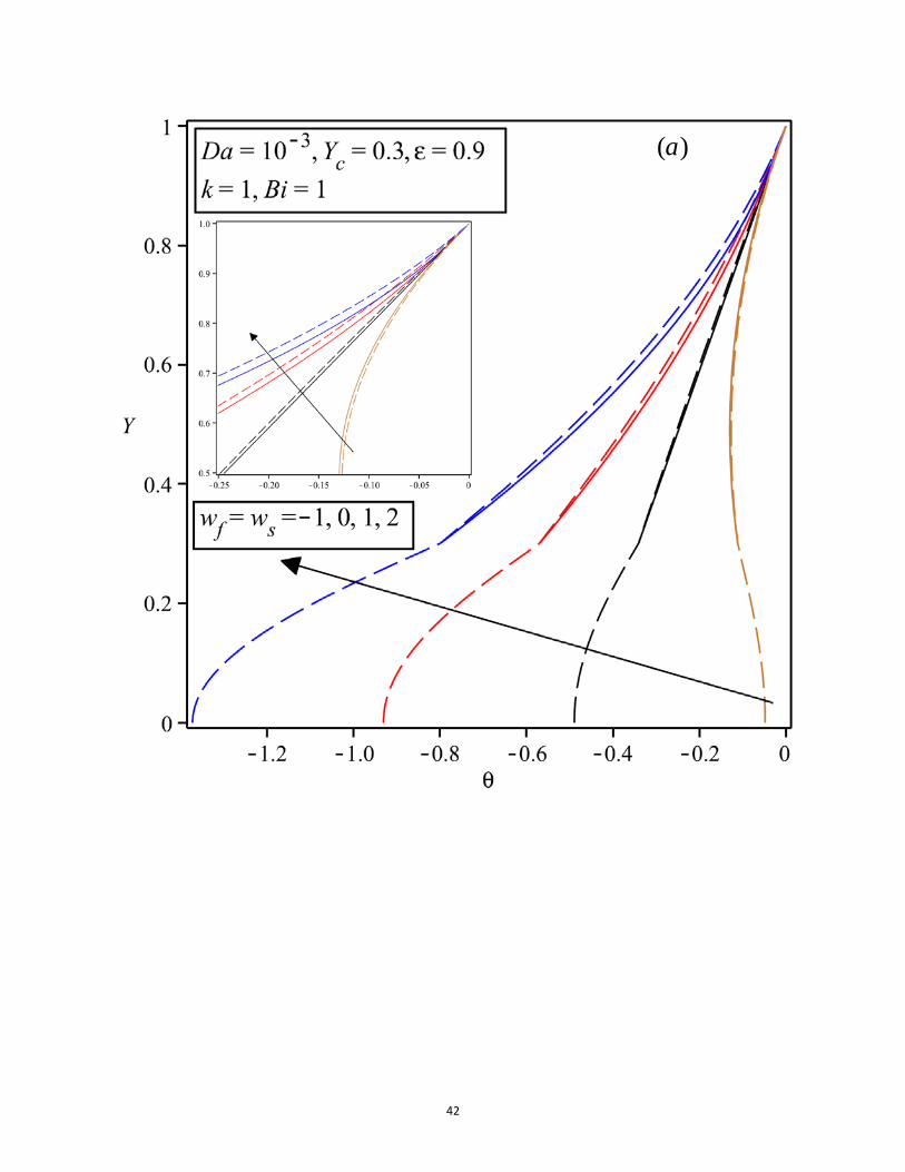
Figures 4-8 depict the temperature distribution within the channel with varying values of internal heat sources,
Darcy number, porosity and conductivity ratio. Figure 4 shows the effects of thermal conductivity parameter and
internal heat sources on the solid and fluid temperature fields. In Fig. 4a the solid and fluid source terms have

18
identical numerical values. Under this condition, it is observed that when the thermal conductivity ratio is equal to
unity the difference between the solid and fluid phases’ temperatures is quite small. However, for the thermal
conductivity ratios different to one, the temperature difference between the two phases rises. Figure 4a, further,
shows that depending upon the value of conductivity ratio the temperature of the solid phase within the porous phase
can be either lower or higher than that of the fluid phase of the porous section. Limiting the heat generation to either
fluid or solid phase in Figs. 4b and c leads to significant deviation from the pattern observed in Fig. 4a. The
temperature differences, between solid and fluid phases, are now always considerable and feature less sensitivity to
the thermal conductivity ratio. Further, as expected, the phase with internal heat generation features a higher
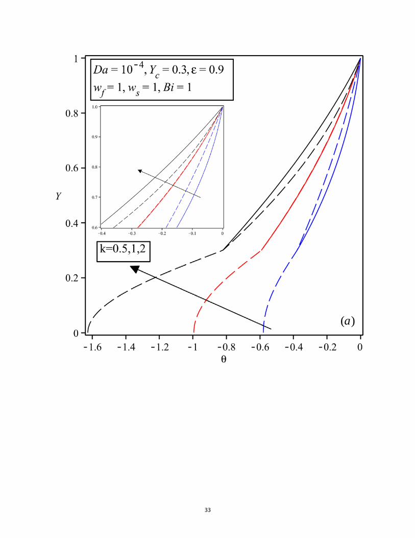
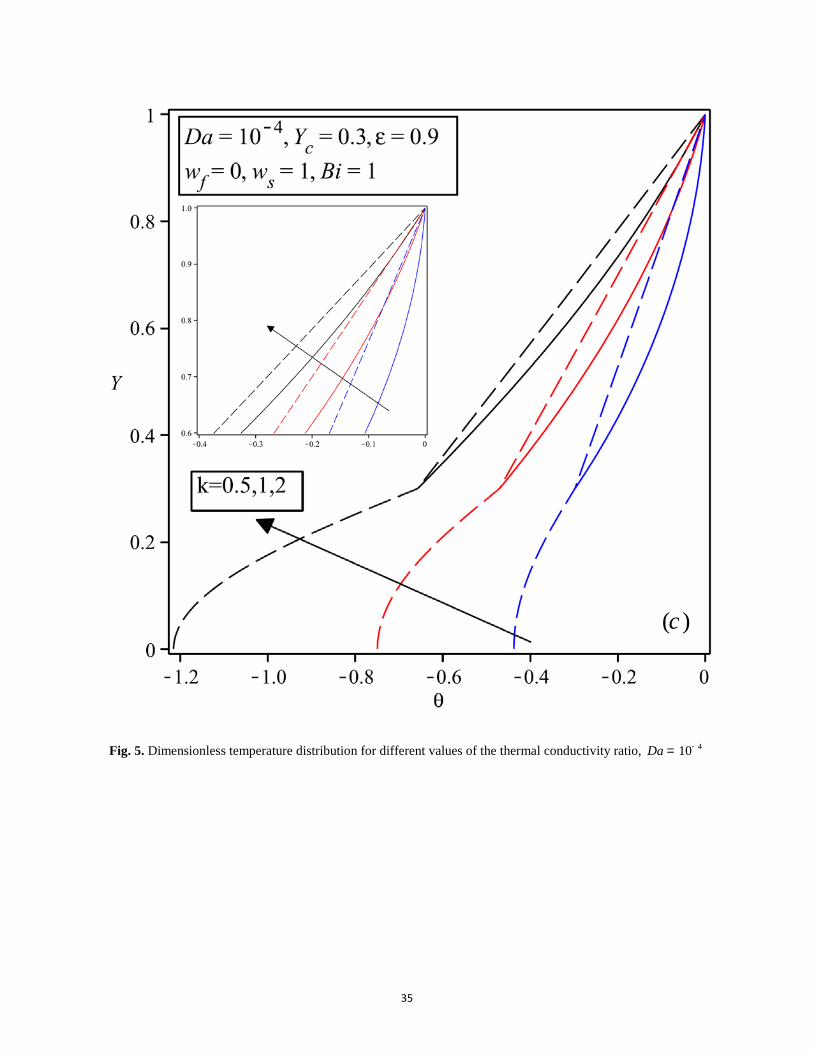
temperature. Figure 5 shows the temperature distribution at the same values of dimensionless parameters as Fig. 4,
with the exception of Darcy number which has been lowered to 410Da -= . Similar to Fig. 4, different combinations
of internal energy source terms have been investigated. A comparison between these two figures indicates that the
general trend observed in Fig. 4 remains unchanged at lower value of Darcy number shown in Fig. 5. However, the
differences between the solid and fluid temperatures have signified in Fig. 5. Interestingly, in Fig. 5a and under the
same strengths of solid and fluid source terms, the solid and fluid temperature difference remains negligible.
However, this is not the case for the two other cases (Figs. 5b and c), in which heat is generated only in one phase.
Figures 6 and 7 demonstrate the influences of the thickness of the porous insert upon the temperature distribution
within the channel. The values of thermal conductivity, k, in Figs. 6 and 7 have been, respectively, set to 1 and 5.
Various combinations of the solid and fluid source terms have been considered in these figures. A careful inspection
of these figures reveals that depending on the strength of the thermal source terms, varying the thickness of the
porous section may switch the hottest phase within the system from solid to fluid or vice versa. However, this is not
always the case and under some circumstances either of the solid or fluid phases remains always the hottest phase
within the porous region. For instance, in Figs. 6a and c the solid phase is always the hottest phase, while Fig. 6b
shows that changing the thickness of the porous region can change the hottest phase from solid to fluid. The
phenomenon of swapping the hot and cold phases in the porous media is called bifurcation and has been, already,
analysed with LTNE model in a number of configurations [29,31,42,57]. The bifurcation phenomenon is also clearly
seen in Figs. 7a and b. There is bifurcation in Fig. 7a under identical strengths of the solid and fluid thermal source
terms. In this figure, when the dimensionless thickness of the clear section is 0.1, the solid phase of the porous
section has a higher temperature compared with the fluid phase. However, when the non-dimensional height of the
clear section increases to 0.3 or 0.5 this trend is reversed and the temperature of the fluid phase becomes higher than
that of the solid phase. There is a similar trend in Fig. 7b. However, when heat generation is limited to the solid
phase (as in Fig. 7c) bifurcation disappears. Further, there exists another important feature in Fig. 6. The
dimensionless temperature for the centreline of the channel, 0Y = , may increase or decrease by increasing the
value of cY . For example, in Fig. 6a by increasing the clear section’s thickness from 0.1 to 0.3 the dimensionless
temperature at the centreline of the channel decreases. Nonetheless, further increasing of the value of cY to 0.5
increases the dimensionless temperature of the centreline. Since the dimensionless temperature of the upper part of
the channel has been set to zero, under most circumstances, this temperature can be regarded as the largest

19
temperature difference between the solid and fluid phases and the channel’s wall. It is should be noted that in case of
excessive internal heat generation, it is possible to have a region of the channel with higher temperature compared to
that of the wall. However, such extreme cases are not considered in this work.
Figure 8 shows the effects of variations in internal heat sources on the temperature fields. In Fig. 8a solid and fluid
thermal source terms vary equally and always maintain the same value. However, the solid heat source in Fig. 8b is
set to zero and only the fluid source term varies. Expectedly, the non-dimensional temperatures in the system
correlate with the level of exothermicity. In Fig. 8a, as the strength of internal exothermicity decreases and
approaches the endothermic case, the difference between the temperature of the solid and fluid phases within the
porous section decreases. This behaviour changes in Fig. 8b, here the variation in exothermicity of the fluid phase
causes a bifurcation with significant temperature differences between the solid and fluid phase. Similar trends have
been reported in other porous systems with internal heat sources and sinks [29].
Figures 9-11 depict variations of the maximum temperature difference between the wall and the fluid in the clear
region as a result of changes in the thickness of the clear region and, for a given set of parameters. As discussed
earlier, this temperature difference is represented by the dimensionless temperature on the centreline of the channel.
It is clear from Figs. 9-11, that variation of the porous thickness generates a minimum value of the dimensionless
temperature of the centreline. This temperature is the highest achievable temperature difference between the fluid
and the wall. Starting from zero thickness of the clear section, increasing this thickness causes an increase in the
magnitude of the highest temperature difference. The temperature difference then reaches its maximum value and
subsequently starts to decrease. It is important to note that the described trend is the reverse of that of 𝜃𝑓1(0) in
Figs. 9-11, as 𝜃𝑓~(𝑇𝑓 − 𝑇𝑤) (see Eq. 13) and therefore the values of 𝜃𝑓 are always negative. Figure 9 indicates that
the magnitude of the temperature difference decreases by decreasing the thermal conductivity ratio. Further, the
maximum value of the temperature difference, between the fluid and the channel wall, increases by decreasing the
Darcy number (Fig. 10), and by increasing the porosity of the porous section of the channel (Fig. 11).
The ratio of the interface heat flux and heat flux of the channel’s wall, denoted by γ , versus the thickness of the
clear region has been illustrated in Figs. 12 and 13. These figures show that as the thickness of the clear region
increases, the heat flux ratio rises and reaches a maximum. This is then followed by a decline of the heat flux ratio
such that it approaches unity in the limit of fully clear channel, which is an anticipated behaviour. Further, as the
Darcy number decreases, the maximum value of heat flux ratio decreases in value and shifts towards higher
thicknesses of the clear region. It is clear from Fig. 12 that the heat flux ratio increases with Darcy number. The
influences of the internal heat sources upon the heat flux ratio have been investigated in Fig. 13. This figure shows
that in exothermic cases as the thickness of the clear section increases, the parameter γ starts to increase versus the
clear region thickness. Similar to that discussed in Fig. 12, it reaches a maximum value and then decays. However,
the neutral and endothermic cases ( 0f sw w= = and -1) remain as exceptions to this trend, in which the initial rise
is followed by a plateau or the trend is totally reversed. The behaviour observed in Figs. 12 and 13 is qualitatively
consistent with those reported in other heat generating/consuming porous systems under forced convection [29]. The

20
negative heat flux ratio for 1f sw w= = - in Fig. 13 means that in this case the heat flux at the interface is from
fluid to porous section. This is due to the endothermic processes occurring in both fluid and solid parts of the
system. As the thickness of the porous section is high when cY has a low numerical value, the thermal energy
consumption in the porous section is higher than the energy consumption in the clear section. Hence, the heat flux at
the interface is towards the porous medium. This behaviour is related to the bifurcation phenomenon discussed
earlier, which has been also detected in other endothermic porous systems [29].
Table 1 compares Nusselt numbers calculated under LTE and LTNE models with varying values of the porous
thickness and porosity and for an exothermic case. The tabulated results clearly show that the differences between
the outcomes of these two models are mostly non-negligible. Significant differences between the values of Nusselt
number under LTE and LTNE have been previously reported [33]. The data in Table 1 are presented to extend the
existing datasets to the cases with internal exothermicity. They, further, provide a means of comparison and
validation for the future theoretical and numerical results. Figures 14 to 17 put forward more detailed information
about the behaviour of the Nusselt number due to the variations in the pertinent parameters. Figure 14 shows that, at
high porous thicknesses the difference between the Nusselt numbers for LTE and LTNE is significant and cannot be
neglected. In other words, in this limit LTE results are highly inaccurate. This remains true even for thermal
conductivity ratio of one. Figures 15-17 depict the variation of Nusselt number versus the clear section thickness.
These figures show that, in general, as the thickness of the clear region increases from zero the Nusselt number
decreases sharply and reaches a minimum value. Further increase in the thickness of the clear region reverses this
trend and the Nusselt number starts to gain higher values. Therefore, when partial filling is implemented in these
channels to compensate the pump costs, special attention should be paid to avoid the particular porous thickness
which minimises the Nusselt number. This statement is in keeping with the earlier findings of Maerefat et al. [58],
who conducted numerical analysis on a configuration similar to Fig. 1 but considered only the LTE condition.
Figure 15 shows the effects of variations in Darcy number upon the value of Nusselt number. It is clear from this
figure that decreasing Darcy number results in increasing the value of Nusselt number. Once again this matches the
earlier findings of the analyses under LTE assumptions [58]. It is, however, noted that this agreement is qualitative
and as Table 1 and Fig. 14 show there could be considerable differences between the Nusselt numbers predicted by
LTE and LTNE models. Figures 16 and 17 show the effects of thermal conductivity ratio and porosity on the
Nusselt number. These figures indicate that Nusselt number decreases with increasing the thermal conductivity ratio
and porosity, respectively.
5.2. Local and total entropy generation
The effects of pertinent parameters on the local and total entropy generation rates in the investigated configuration
have been illustrated in Figs. 18-23. In particular, the influences of the modifications in internal energy source terms,
upon the rate of entropy generation are investigated in these figures. Figure 18 shows the effect of varying the clear
section thickness on the local entropy generation within the channel for three different sets of thermal source terms.
It can be, clearly, seen in this figure that changing the clear section thickness from 0.3 to 0.4, decrease the local

21
entropy generation. The change of entropy generation in both clear and porous section of the channel is quite
substantial, and this is the case for all the investigated sets of the internal energy source terms in Figs. 18a-c. This
behaviour is in accordance with the earlier results, which illustrated the strong effects of the channel configuration
upon the hydrodynamics and heat transfer characteristics of the problem. Equations (25 a-c) clearly show that
modifications of temperature and velocity fields affect the generation of entropy within the channel. A comparison
of Figs. 18a-c reveals that the local generation of entropy is strongly affected by the thermal energy source terms.
This is such that the values of local entropy generation for the case of identical solid and fluid exothermicity
strengths (Fig. 18a) are between two to three times more than those in the case of exothermicity in solid only (Fig.
18c). Further, variations in the thermal source terms can change the phase with higher entropy generation. This can
be seen more clearly from the insets in Figs. 18a-c and can be regarded as a bifurcation of entropy generation.
Figure 19 illustrates the effect of thermal conductivity ratio on the local entropy generation. This figure shows that
when the thermal conductivity ratio is unity, the local entropy generations in both solid and fluid phases of the
porous section are close to each other. Depending upon the state of the thermal sources either of fluid or solid phases
can have the maximum rate of entropy generation while, the difference between the two remains negligibly small.
However, as the thermal conductivity ratio increases to 2k = the value of the local entropy generation rates in the
solid and fluid phases of the porous section are completely different. Under this condition the entropy generation
rate in the solid phase exceeds that in the fluid phase by a significant amount. The local entropy generation rates
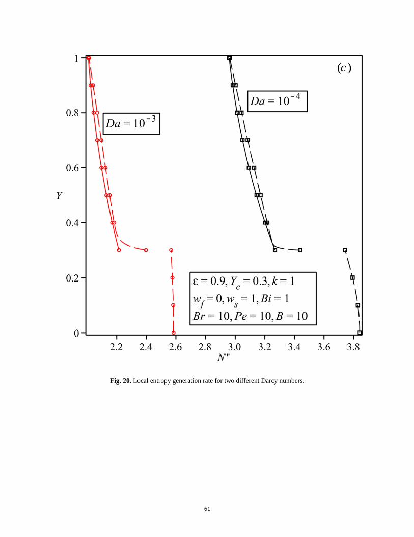
under two different Darcy numbers are compared in Fig. 20. This figure shows that decreasing Darcy number
increases the local entropy generation rate within the thermal system.
Three sample calculations regarding the total entropy generation rate within the system have been conducted. Figs.
21-23 show the outcome of these calculations. These figures show the changes in the total entropy generation versus
the thickness of the clear region and for varying values of thermal conductivity ratio, Peclet number and
exothermicity. Generally, in all these figures the total entropy generation rate goes through a sharp decrease by
increasing the clear section thickness. It reaches a minimum value and then starts to increase by a small amount.
This clearly shows the highly irreversible situation encountered when thick porous inserts are placed in the channel.
It is, therefore, inferred from these figures that, for the investigated system and within the considered range of
parameters, total filling is the worst case from the view of the second law of thermodynamics. However, with partial
filling the total entropy generation rate can be minimised and an optimum values for parameter cY , which has a
direct connection with the porous thickness of the system, can be achieved. The total entropy generation rate
increases with thermal conductivity ratio (Fig. 21), decreases by Peclet number (Fig. 22), and increases with energy
sources regarding exothermic or endothermic characteristic of the system (Fig. 23). Further inspection of these
figures show that the optimum value of the clear section thickness for achieving the minimum value of the total
entropy generation rate shifts towards higher values of 𝑌𝑐 through changing a number of parameters. These include
increasing the thermal conductivity ratio (Fig. 21), decreasing Peclet number (Fig. 22), and increasing the internal
energy sources (Fig. 23). That is to say, if the total entropy generation is higher than this value for a given set of
parameters, the minimum total entropy generation rate can be achieved by increasing the thickness of the clear
section.

22
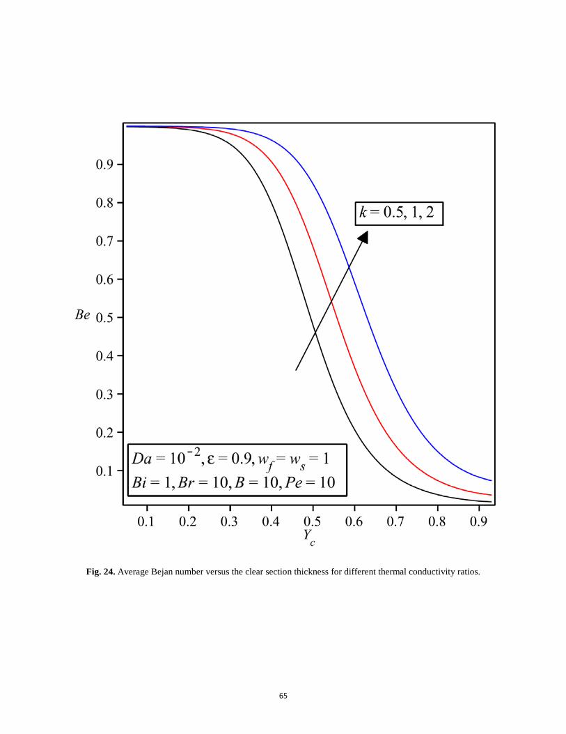
5.3. Average Bejan number
Figures 24-26 illustrate the variation of average Bejan number with thickness of the clear section and the thermal
conductivity ratio (Fig. 24), Peclet number (Fig. 25) and energy sources in both clear and porous sections (Fig. 26).
In all of these figures it is seen that when the clear section thickness is small, almost all of the entropy generation
rate is due to heat transfer, i.e., Bejan number is near to unity. However, when the height of the clear section
thickness is large, Bejan number is much less than 0.5, which implies that the entropy generation due to viscous
dissipation overtakes the entropy generation due to heat transfer. It is interesting to note here that, from Eq. (26) the
Peclet number has inverse effect on the entropy generation due to heat transfer and therefore to Bejan number. This
can be clearly seen in Fig. 25 when increasing the value of Peclet number decreases Bejan number. Figure 26 shows
the effect of energy sources on Bejan number. As expected, increasing the value of internal heat generation,
increases the rate of internal heat transfer within the system and consequently it increases the entropy generation rate
due to heat transfer.
6. Conclusions
A two dimensional, axisymmetric channel with porous inserts attached to the walls and under constant wall heat
flux, was considered. The channel included a steady, laminar and fully developed flow of a constant density fluid. It
was assumed that the solid and fluid phases can feature internal heat sources and the system is under LTNE. Darcy-
Brinkman model of transport of momentum along with model A of Yang and Vafai [31] for the description of
porous-fluid interface thermal boundary condition, were utilised. The problems of forced convection and entropy
generation were investigated in this configuration. Analytical solutions were developed for the velocity,
temperature, Nusselt number and, local and total entropy generation within the channel. In keeping with the previous
investigations, it was shown that the existence of internal heat sources can heavily affect the thermal equilibrium
state and invalidate LTE approach. Further, it was shown that variations in the internal heat sources could lead to a
bifurcation phenomenon in which the hottest phase in the porous medium is exchanged between the fluid and solid
parts of the system. Compared to the previous studies under LTE, consideration of LTNE and the existence of
internal heat sources appeared to have no major influence on the qualitative behaviour of the Nusselt number.
However, the results showed that the numerical values of the predicted Nusselt numbers under LTNE could be
markedly different to those obtained through LTE approach. Analysis of the local generation of entropy revealed
that this property of the system is heavily affected by the configuration of the channel. This was such that an
increase in the thickness of the porous inserts significantly increased the rate of entropy generation. Considering the
total entropy generation in the channel, an optimal value for the thickness of the porous insert was found and the
influences of pertinent parameters upon this optimal thickness were discussed. The results of this work provide a
guide through the complex physical behaviour of fluid conduits partially filled with porous media, which include
internal heat sources. They can be, further, used for the validation of numerical and other theoretical analyses.
Acknowledgments

23
This work was supported by the Hong Kong Research Grants Council (project no. CityU 125412) and NSAF (grant
no. U1330132).
References
[1] Bergman TL, Lavine AS, Incropera FP, DeWitt DP. Introduction to Heat Transfer. 6th ed. John Wiley and Sons, Inc.; 2011.
[2] Bejan A. Entropy Generation Minimization: The Method of Thermodynamic Optimization of Finite-Size Systems and Finite-Time Processes. CRC Press; 1995.
[3] Bejan A. Entropy Generation Through Heat and Fluid Flow. New York: Wiley; 1982.
[4] Torabi M, Zhang K. Heat transfer and thermodynamic performance of convective–radiative cooling double layer walls with temperature-dependent thermal conductivity and internal heat generation. Energy Convers Manag 2015;89:12–23.
[5] Aziz A, Khan WA. Classical and minimum entropy generation analyses for steady state conduction with temperature dependent thermal conductivity and asymmetric thermal boundary conditions: Regular and functionally graded materials. Energy 2011;36:6195–207.
[6] Torabi M, Zhang K, Yang G, Wang J, Wu P. Temperature distribution, local and total entropy generation analyses in asymmetric cooling composite geometries with multiple nonlinearities: Effect of imperfect thermal contact. Energy 2014;78:218–34.
[7] Elazhary AM, Soliman HM. Entropy generation during fully-developed forced convection in parallel-plate micro-channels at high zeta-potentials. Int J Heat Mass Transf 2014;70:152–61.
[8] Anand V. Slip law effects on heat transfer and entropy generation of pressure driven flow of a power law fluid in a microchannel under uniform heat flux boundary condition. Energy 2014;76:716–32.
[9] Rashidi MM, Ali M, Freidoonimehr N, Nazari F. Parametric analysis and optimization of entropy generation in unsteady MHD flow over a stretching rotating disk using artificial neural network and particle swarm optimization algorithm. Energy 2013;55:497–510.
[10] Aziz A, Torabi M. Transient response and entropy generation minimisation of a finite size radiation heat shield with finite heat capacity and temperature-dependent emissivities. Int J Exergy 2013;12:87.
[11] Nield DA, Bejan A. Convection in Porous Media. 4th editon. New York: Speringer; 2013.
[12] Vafai K. Handbook of Porous Media. Second Edi. CRC Press; 2005.
[13] Nield D. Effects of local thermal nonequilibrium in steady convective processes in a saturated porous medium: forced convection in a channel. J Porous Media 1998;1:181–6.
[14] Mahmoudi Y, Karimi N. Numerical investigation of heat transfer enhancement in a pipe partially filled with a porous material under local thermal non-equilibrium condition. Int J Heat Mass Transf 2014;68:161–73.
[15] Mahmoudi Y, Karimi N, Mazaheri K. Analytical investigation of heat transfer enhancement in a channel partially filled with a porous material under local thermal non-equilibrium condition: Effects of different thermal boundary conditions at the porous-fluid interface. Int J Heat Mass Transf 2014;70:875–91.

24
[16] Karimi N, Mahmoudi Y, Mazaheri K. Temperature fields in a channel partially filled with a porous material under local thermal non-equilibrium condition - An exact solution. Proc Inst Mech Eng Part C J Mech Eng Sci 2014;288:2778–89.
[17] Alazmi B, Vafai K. Constant wall heat flux boundary conditions in porous media under local thermal non-equilibrium conditions. Int J Heat Mass Transf 2002;45:3071–87.
[18] Jiang F, Chen J, Huang W, Luo L. A three-dimensional transient model for EGS subsurface thermo-hydraulic process. Energy 2014;72:300–10.
[19] Bortolozzi HA, Deiber JA. Comparison between two- and one-field models for natural convection in porous media. Chem Eng Sci 2001;56:157–72.
[20] Kim SJ, Jang SP. Effects of the Darcy number, the Prandtl number, and the Reynolds number on local thermal non-equilibrium. Int J Heat Mass Transf 2002;45:3885–96.
[21] Khashan SA, Al-Amiri AM, Al-Nimr MA. Assessment of the local thermal non-equilibrium condition in developing forced convection flows through fluid-saturated porous tubes. Appl Therm Eng 2005;25:1429–45.
[22] Chen GM, Tso CP. A two-equation model for thermally developing forced convection in porous medium with viscous dissipation. Int J Heat Mass Transf 2011;54:5406–14.
[23] Chen GM, Tso CP. Forced convection with viscous dissipation using a two-equation model in a channel filled by a porous medium. Int J Heat Mass Transf 2011;54:1791–804.
[24] Ouyang X-L, Vafai K, Jiang P-X. Analysis of thermally developing flow in porous media under local thermal non-equilibrium conditions. Int J Heat Mass Transf 2013;67:768–75.
[25] Dehghan M, Valipour MS, Saedodin S. Perturbation analysis of the local thermal non-equilibrium condition in a fluid-saturated porous medium bounded by an iso-thermal channel. Transp Porous Media 2014;102:139–52.
[26] Dehghan M, Jamal-Abad MT, Rashidi S. Analytical interpretation of the local thermal non-equilibrium condition of porous media imbedded in tube heat exchangers. Energy Convers Manag 2014;85:264–71.
[27] Ochoa-Tapia JA, Whitaker S. Heat transfer at the boundary between a porous rnedium and a homogeneous fluid. Int J Heat Mass Transf 1997;40:2691–707.
[28] Arpino F, Carotenuto A, Massarotti N, Mauro A. New solutions for axial flow convection in porous and partly porous cylindrical domains. Int J Heat Mass Transf 2013;57:155–70.
[29] Karimi N, Agbo D, Talat Khan A, Younger PL. On the effects of exothermicity and endothermicity upon the temperature fields in a partially-filled porous channel. Int J Therm Sci 2015;96:128–48.
[30] Yang K, Vafai K. Restrictions on the validity of the thermal conditions at the porous-fluid interface—An exact solution. J Heat Transfer 2011;133:112601.
[31] Yang K, Vafai K. Analysis of heat flux bifurcation inside porous media incorporating inertial and dispersion effects – An exact solution. Int J Heat Mass Transf 2011;54:5286–97.

25
[32] Xu HJ, Qu ZG, Lu TJ, He YL, Tao WQ. Thermal modeling of forced convection in a parallel-plate channel partially filled with metallic foams. J Heat Transfer 2011;133:092603.
[33] Xu HJ, Qu ZG, Tao WQ. Analytical solution of forced convective heat transfer in tubes partially filled with metallic foam using the two-equation model. Int J Heat Mass Transf 2011;54:3846–55.
[34] Mahmoudi Y, Maerefat M. Analytical investigation of heat transfer enhancement in a channel partially filled with a porous material under local thermal non-equilibrium condition. Int J Therm Sci 2011;50:2386–401.
[35] Qu ZG, Xu HJ, Tao WQ. Fully developed forced convective heat transfer in an annulus partially filled with metallic foams: An analytical solution. Int J Heat Mass Transf 2012;55:7508–19.
[36] Yang C, Nakayama A, Liu W. Heat transfer performance assessment for forced convection in a tube partially filled with a porous medium. Int J Therm Sci 2012;54:98–108.
[37] Shokouhmand H, Jam F, Salimpour MR. Optimal porosity in an air heater conduit filled with a porous matrix. Heat Transf Eng 2009;30:375–82.
[38] Hooman K, Ejlali A. Entropy generation for forced convection in a porous saturated circular tube with uniform wall temperature. Int Commun Heat Mass Transf 2007;34:408–19.
[39] Morosuk T V. Entropy generation in conduits filled with porous medium totally and partially. Int J Heat Mass Transf 2005;48:2548–60.
[40] Mahdavi M, Saffar-Avval M, Tiari S, Mansoori Z. Entropy generation and heat transfer numerical analysis in pipes partially filled with porous medium. Int J Heat Mass Transf 2014;79:496–506.
[41] Buonomo B, Manca O, Lauriat G. Forced convection in micro-channels filled with porous media in local thermal non-equilibrium conditions. Int J Therm Sci 2014;77:206–22.
[42] Torabi M, Zhang K, Yang G, Wang J, Wu P. Heat transfer and entropy generation analyses in a channel partially filled with porous media using local thermal non-equilibrium model. Energy 2015;82:922–38.
[43] Bandhauer TM, Garimella S, Fuller TF. A critical review of thermal issues in lithium-ion batteries. J Electrochem Soc 2011;158:R1–25.
[44] Zheng K, Sun Q, Ni M. Local non-equilibrium thermal effects in solid oxide fuel cells with various fuels. Energy Technol 2013;1:35–41.
[45] Phanikumar MS, Mahajan RL. Non-Darcy natural convection in high porosity metal foams. Int J Heat Mass Transf 2002;45:3781–93.
[46] Tasnim SH, Shohel M, Mamun MAH. Entropy generation in a porous channel with hydromagnetic effect. Exergy, An Int J 2002;2:300–8.
[47] Ingham DB, Pop I. Transport Phenomena in Porous Media. Elsevier; 2005.
[48] Salem AM. Entropy generation for magnetohydrodynamic heat transfer over a non-isothermal stretching sheet with variable viscosity. IMA J Appl Math 2014.
[49] Aziz A, Khan WA. Entropy generation in an asymmetrically cooled slab with temperature-dependent internal heat generation. Heat Transf Res 2012;41:260–71.

26
[50] Mahmud S, Fraser RA. Flow, thermal, and entropy generation characteristics inside a porous channel with viscous dissipation. Int J Therm Sci 2005;44:21–32.
[51] Mahian O, Mahmud S, Heris SZ. Analysis of entropy generation between co-rotating cylinders using nanofluids. Energy 2012;44:438–46.
[52] Mahian O, Mahmud S, Pop I. Analysis of first and second laws of thermodynamics between two isothermal cylinders with relative rotation in the presence of MHD flow. Int J Heat Mass Transf 2012;55:4808–16.
[53] Yazdi MH, Abdullah S, Hashim I, Sopian K. Entropy generation analysis of open parallel microchannels embedded within a permeable continuous moving surface: application to magnetohydrodynamics (MHD). Entropy 2011;14:1–23.
[54] Torabi M, Aziz A. Entropy generation in a hollow cylinder with temperature dependent thermal conductivity and internal heat generation with convective–radiative surface cooling. Int Commun Heat Mass Transf 2012;39:1487–95.
[55] Mahmoudi AH, Pop I, Shahi M, Talebi F. MHD natural convection and entropy generation in a trapezoidal enclosure using Cu–water nanofluid. Comput Fluids 2013;72:46–62.
[56] Torabi M, Zhang K. Temperature distribution , local and total entropy generation analyses in MHD porous channels with thick walls. Energy 2015;87:540–54.
[57] Yang K, Vafai K. Transient aspects of heat flux bifurcation in porous media: An exact solution. J Heat Transfer 2011;133:052602.
[58] Maerefat M, Mahmoudi SY, Mazaheri K. Numerical simulation of forced convection enhancement in a pipe by porous inserts. Heat Transf Eng 2011;32:45–56.

27
Fig. 1. Configuration of the channel partially filled with a porous material.

28
Fig. 2. Dimensionless velocity profile for different values of the thickness of the clear section, 310Da -=

29
Fig. 3. Dimensionless velocity profile for different values of the thickness of the clear section, 410Da -=

30
( )a

31
( )b

32
Fig. 4. Dimensionless temperature distribution for different values for the thermal conductivity ratio, 310Da -=
( )c
33
( )a

34
( )b
35
Fig. 5. Dimensionless temperature distribution for different values of the thermal conductivity ratio, 410Da -=
( )c

36
( )a

37
( )b

38
Fig. 6. Dimensionless temperature distribution for different values of the clear section thickness, 1k = .
( )c

39
( )a

40
( )b

41
Fig. 7. Dimensionless temperature distribution for different values of the clear section thickness, 5k = .
( )c
42
( )a

43
Fig. 8. Dimensionless temperature distribution for different values of the energy source terms.
( )b

44
Fig. 9. Dimensionless temperature on the centreline of the channel versus the clear section thickness for different
thermal conductivity ratios.

45
Fig. 10. Dimensionless temperature on the centreline of the channel versus the clear section thickness for different
Darcy numbers.

46
Fig. 11. Dimensionless temperature on the centreline of the channel versus the clear section thickness for different
porosity values.

47
Fig. 12. Heat flux ratio γ versus the clear section thickness for different Darcy numbers.

48
Fig. 13. Heat flux ratio γ versus the clear section thickness for different values of the energy source terms.

49
Fig. 14. Nusselt number versus the clear section thickness for both LTNE (solid line) and LTE (dash line) models.

50
Fig. 15. Nusselt number versus the clear section thickness for different Darcy numbers.

51
Fig. 16. Nusselt number versus the clear section thickness for different thermal conductivity ratios.

52
Fig. 17. Nusselt number versus the clear section thickness for different porosities.

53
( )a

54
( )b

55
Fig. 18. Local entropy generation rate for 0.3cY = and 0.4cY = .
( )c

56
( )a

57
( )b

58
Fig. 19. Local entropy generation rate for two different thermal conductivity ratios.
( )c

59
( )a

60
( )b
61
Fig. 20. Local entropy generation rate for two different Darcy numbers.
( )c

62
Fig. 21. Total entropy generation rate versus the clear section thickness for different thermal conductivity ratios.

63
Fig. 22. Total entropy generation rate versus the clear section thickness for different Peclet numbers.

64
Fig. 23. Total entropy generation rate versus the clear section thickness for different energy sources.
65
Fig. 24. Average Bejan number versus the clear section thickness for different thermal conductivity ratios.

66
Fig. 25. Average Bejan number versus the clear section thickness for different Peclet numbers.

67
Fig. 26. Average Bejan number versus the clear section thickness for different energy sources.

68
Table 1. Comparison of Nusselt number with LTNE and LTE models for 310, 10 , 0.9, 1f sBi Da w wε−= = = = =
1k = 2k = 5k = 10k =
0.3cY = LTE 4.48 5.82 8.31 10.30
LTNE 4.48 4.06 3.87 3.82
0.4cY = LTE 4.46 5.52 7.25 8.45
LTNE 4.46 4.61 4.86 4.97
0.5cY = LTE 4.61 5.47 6.74 7.53
LTNE 4.61 5.05 5.64 5.92