heat transfer phenomenon of heated cylinder at...
TRANSCRIPT

HEAT TRANSFER PHENOMENON OF HEATED CYLINDER AT VARIOUS
LOCATIONS IN A SQUARE CAVITY
MOHD RUZAINI BIN ZAKARIA
Thesis submitted in fulfillment of the requirements
for the award of the degree of
Bachelor of Mechanical Engineering
Faculty of Mechanical Engineering
UNIVERSITI MALAYSIA PAHANG
NOVEMBER 2009

ii
SUPERVISOR’S DECLARATION
I hereby declare that I have checked this project and in my opinion, this project is adequate
in terms of scope and quality for the award of the degree of Bachelor of Mechanical
Engineering.
Signature:
Name of Supervisor: MOHAMAD MAZWAN BIN MAHAT
Position: LECTURER
Date: 24 NOVEMBER 2008
iii
STUDENT’S DECLARATION
I hereby declare that the work in this project is my own except for quotations and
summaries which have been duly acknowledged. The project has not been accepted for any
degree and is not concurrently submitted for award of other degree.
Signature:
Name: MOHD RUZAINI BIN ZAKARIA
ID Number: MA06051
Date: 20 NOVEMBER 2009

iv
ACKNOWLEDGEMENTS
I am grateful and would like to express my sincere gratitude to my supervisor Mr
Mohamad Mazwan Bin Mahat for his germinal ideas, invaluable guidance, continuous
encouragement and constant support in making this research possible. He has always
impressed me with his outstanding professional conduct, his strong conviction for science,
and his belief that this is only a start of a life-long learning experience. I appreciate his
consistent support from the first day I applied to graduate program to these concluding
moments. I am truly grateful for his progressive vision about my training in science, his
tolerance of my naïve mistakes, and his commitment to my future career. I also would like
to express very special thanks supervisor for the suggestions and co-operation throughout
the study. I also sincerely thanks for the time spent proofreading and correcting my many
mistakes.
I acknowledge my sincere indebtedness and gratitude to my parents and for their
understanding. My sincere thanks go to all my friend and lecturer, who helped me in many
ways and made my stay at UMP pleasant and unforgettable. Many special thanks go to all
of people that involve in this study for their excellent co-operation, inspirations and
supports during this study. I cannot find the appropriate words that could properly describe
my appreciation for their devotion, support and faith in my ability to attain my goals.

v
ABSTRACT
In this thesis, the theory of lattice Boltzmann method is been described in first chapter. The
lattice Boltzmann equation method has been found to be useful in many application
involving interfacial dynamics and complex boundaries. First, the introduction of this
report is described the objective of the project. This project objective is to study the plume
behavior of heated cylinder at various locations in square cavity. Next, the problem
statement is explained in further detailed. The problems solve using the lattice Boltzmann
method theory and some flow simulation. The background of the project is relating to the
lattice Boltzmann method equation that is involving the Navier-Stoke equation, the
governing equation and Bhatnagar-Gross-Krook (BGK) approximation. Then, the literature
will explain and described further detail about the lattice Boltzmann method. The
methodology is the simulation of the isothermal and thermal of the lattice Boltzmann. The
isothermal include the Poiseuille and Coutte flow. The thermal include the Porous Coutte
flow. The isothermal and thermal of lattice Boltzmann equation have been derived from the
Boltzmann equation by discretization in both time and phase space. The result of heated
cylinder at various locations in square cavity at different Rayleigh number that has been
done compute that when the Rayleigh number is increase the flow will become distorted
and the plume will emerge in the enclosure. This is because of the buoyancy induced and
convection become more predominant than conduction. The isotherms move upward and
larger plumes exist on the top of the inner square, which gives rise to the stronger thermal
gradient on the top of the enclosure. Therefore, the flow strongly imposes on the above of
the enclosure, which also cause the form of a thinner thermal boundary layer in this area
and develops the heat transfer.
vi
ABSTRAK
Tesis ini menerangkan teori kaedah kekisi Boltzmann dalam bahagian satu. Persamaan
kekisi Boltzmann telah ditemui amat berguna kerana membabitkan dinamik antara muka
dan sempadan kompleks. Pertama, pendahuluan menerangkan tentang objektif projek ini..
Objektif projek ini adalah untuk mengkaji sifat pemanasan silinder dalam ruang segi empat.
Seterusnya, permasalahan projek ini diterangkan dengan lebih terperinci. Masalah The
problem is diselesaikan dengan kaedah kekisi Boltzmann dan simulasi aliran. Latar
belakang projek ini berkaitan dengan kaedah kekisi Boltzmann yang membabitkan
persamaan Navier-Stoke dan penghampiran Bhatnagar-Gross-Krook (BGK). Kemudian,
penulisan akan menerangkan lebih lanjut tentang kaedah kekisi Boltzmann. Dalam simulasi
Isothermal dan pemanasan kekisi Boltzmann. Dalam Isothermal terdapat aliran Poiseuille
dan Couette. Dalam pemanasan terdapat aliran Porous Couette. Persamaan Thermal dan
Isothermal Boltzmann diterbitkan daripada persamaan kekisi Boltzmann melalui diskit
masa dan fasa.Hasil pemanasan silinder dalam ruang segi empat pada nombor Rayleigh
yang berlainan menunjukkan apabila nombor Rayleigh meningkat, aliran akan menjadi
bengkok dan bentuk seperti pelepah akan terbentuk dalam ruang tersebut. Ini adalah kerana
apungan berlaku dan konveksi akan menjadi lebih dominan daripanan konduksi. Isotherm
akan bergerak ke atas dan pelepah yang lebih besar akan terbentuk di atas ruang segi empat,
yang mana akan meningkatkan kecerunan suhu di atas ruang segi empat tersebut. Oleh itu,
aliran yang kuat terjadi di atas ruang segu empat tersebut, seterusnya menjadikan lapisan
sempadan suhu menjadi nipis di kawasan ini dan menyebabkan pemindahan haba berlaku.

vii
TABLE OF CONTENTS
Page
SUPERVISOR’S DECLARATION ii
STUDENT’S DECLARATION iii
ACKNOWLEDGEMENTS iv
ABSTRACT v
ABSTRAK vi
TABLE OF CONTENTS vii
LIST OF TABLES ix
LIST OF FIGURES x
LIST OF SYMBOLS xii
LIST OF ABBREVIATIONS xiii
CHAPTER 1 INTRODUCTION 1
1.1 Objective 1
1.2 Problem Statement 1
1.3 Project Background 2
1.4 Project Flow Chart 7
CHAPTER 2 LITERATURE REVIEW 9
2.1 Navier Stoke Equation 9
2.2 Computational fluid dynamics (CFD) 10
2.3 Lattice Boltzmann Method (LBM) 12
2.4 Boltzmann Bhatnagar Gross Krook (BGK) 15
2.5 Poiseuille Flow 19
2.6 Couette Flow 20
2.7 Porous Couette Flow 21
2.8 Natural Convection in Square Cavity 22

viii
CHAPTER 3 METHODOLOGY 24
3.1 Original LBM Algorithm 24
3.2 Simulation of Isothermal Lattice Boltzmann 25
3.2.1 Poiseuille Flow 26
3.2.2 Couette Flow 26
3.3 Simulation of Thermal Lattice Boltzmann 27
3.3.1 Porous Coutte Flow 28
CHAPTER 4 RESULT AND DISCUSSION 30
4.1 Grid Dependence Study 31
4.2 Heated Cylinders at Different Rayleigh Number 34
4.3 Heated Cylinders at Bottom of Enclosure 38
4.4 Heated Cylinders at Top of Enclosure 41
4.5 Relationship of Nusselt Number and Rayleigh Number 43
4.6 Horizontal and Vertical Velocity at Different Rayleigh Number 44
CHAPTER 5 CONCLUSION AND RECOMMENDATIONS 49
5.2 Conclusion 49
5.2 Recommendation 50
REFERENCES 51
APPENDIX 55
A Main Programme Source Code 55

ix
LIST OF TABLES
Table No. Title Page
4.1 Grid dependence study of Ra=105 32
4.2 Grid dependence study of Ra=106 33

x
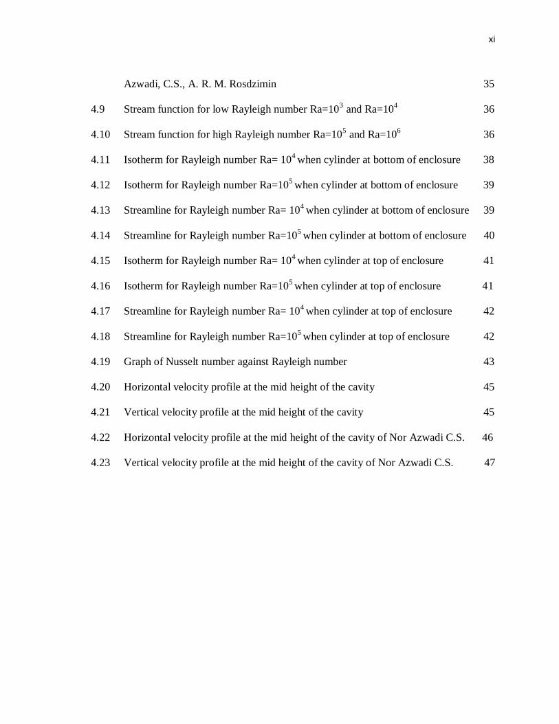
LIST OF FIGURES
Figure No. Title Page
1.1 Lattice Boltzmann method 5
1.2 Project flow chart 8
2.1 Poiseuille flow 20
2.2 Couette flow 21
2.3 Porous Coutte flow 22
2.4 Heated cylinder in square cavity 23
3.1 LBM algorithm flow chart 25
3.2 Poiseuille flow graph 26
3.3 Velocity profiles across the normalized channel width at different times 27
3.4 Porous Couette flow graph at different Reynolds number 29
3.5 Porous Couette flow graph at different Prandtl number 29
4.1 Geometry and boundary condition of heated cylinder in enclosure 30
4.2 The dimension of mesh grid of cylinder and enclosure 31
4.3 Graph of Nusselt number against grid for Ra=105 32
4.4 Graph of Nusselt number against grid for Ra=106 33
4.5 Comparison result of Isotherm for Rayleigh number Ra= 103 and Nor
Azwadi C.S., A. R. M. Rosdzimin 34
4.6 Comparison result of Isotherm for Rayleigh number Ra= 104 and Nor
Azwadi C.S., A. R. M. Rosdzimin 34
4.7 Comparison of result Isotherm for Rayleigh number Ra= 105 and Nor
Azwadi C.S., A. R. M. Rosdzimin 35
4.8 Comparison of result Isotherm for Rayleigh number Ra= 106 and Nor
xi
Azwadi, C.S., A. R. M. Rosdzimin 35
4.9 Stream function for low Rayleigh number Ra=103 and Ra=10
4 36
4.10 Stream function for high Rayleigh number Ra=105 and Ra=10
6 36
4.11 Isotherm for Rayleigh number Ra= 104 when cylinder at bottom of enclosure 38
4.12 Isotherm for Rayleigh number Ra=105 when cylinder at bottom of enclosure 39
4.13 Streamline for Rayleigh number Ra= 104 when cylinder at bottom of enclosure 39
4.14 Streamline for Rayleigh number Ra=105 when cylinder at bottom of enclosure 40
4.15 Isotherm for Rayleigh number Ra= 104 when cylinder at top of enclosure 41
4.16 Isotherm for Rayleigh number Ra=105 when cylinder at top of enclosure 41
4.17 Streamline for Rayleigh number Ra= 104 when cylinder at top of enclosure 42
4.18 Streamline for Rayleigh number Ra=105 when cylinder at top of enclosure 42
4.19 Graph of Nusselt number against Rayleigh number 43
4.20 Horizontal velocity profile at the mid height of the cavity 45
4.21 Vertical velocity profile at the mid height of the cavity 45
4.22 Horizontal velocity profile at the mid height of the cavity of Nor Azwadi C.S. 46
4.23 Vertical velocity profile at the mid height of the cavity of Nor Azwadi C.S. 47
xii
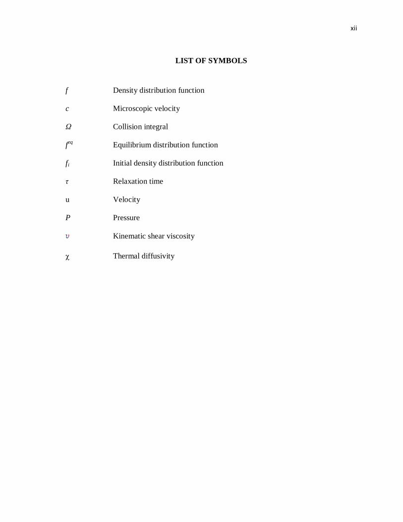
LIST OF SYMBOLS
f Density distribution function
c Microscopic velocity
Ω Collision integral
feq
Equilibrium distribution function
fi Initial density distribution function
τ Relaxation time
u Velocity
P Pressure
Kinematic shear viscosity
χ Thermal diffusivity

xiii
LIST OF ABBREVIATIONS
BGK Bhatnagar-Gross-Krook
CFD Computational fluid dynamic
ELB Entropic lattice Boltzmann
LBE Lattice Boltzmann equation
LBGK Lattice Bhatnagar-Gross-Krook
LBM Lattice Boltzmann method
LGA Lattice gas automata
CHAPTER 1
INTRODUCTION
1.1 OBJECTIVE
This project objective is to study the plume behavior of heated cylinder at
various locations in square cavity. This project also attempts to deal with the analysis of
an investigation of the natural convection of heat transfer in a square enclosure
containing solid cylinder. The effects of the cylinder position on the heat transfer and
the flow structures inside the cavity are to be studied and highlighted.
1.2 PROBLEM STATEMENT
This project is to study the heat transfer phenomenon of heated cylinder at
various locations in square cavity. The project scope is to analysis heat transfer limit to
natural convection only. The problem will be tested at Ra = 105and 10
6. This study will
include the natural convection interactions in a heated cavity with an inner body. A
specifically developed numerical model, based on the lattice Boltzmann method (LBM),
is used for the solutions of the governing equations. Natural convection in heated
enclosures, housing inner bodies has received significant attention because of its interest
and importance in industrial applications. Some applications are solar collectors, fire
research, electronic cooling, aeronautics, chemical apparatus, building constructions and
nuclear engineering. This will contributes to the development of the LBM. Effects of
the cylinder position on the heat transfer and the flow structures inside the cavity are to
be studied and highlighted.

2
1.3 PROJECT BACKGROUND
The Lattice Boltzmann Method (LBM) is another approach to finite difference,
finite element and finite volume method for solving Navier-Stoke Equation. Lattice
Boltzmann approach has found current achievement in the host of fluid dynamical study
including in porous media, magnetohydrodynamics, immiscible fluid and turbulence.
The numerical and experimental study of natural convection of heat transfer in the
partitioned enclosure has received significant interest in the recent year due to the useful
engineering application. The application that related to this project is the solar
collectors, thermal insulation, cooling of the electronic component and designing
building. In nearly all of the earlier studies on natural convection in a square cavity
containing partitions or solid bodies, with or without heat generation, the influence of
radiation is ignored. There have been not many studies on the both heat-transfer
problem involving convection and radiation. On the other hand, it is well recognized
that when natural convection in air is involved, the heat transfers by convection and
radiation are usually of the equal order of magnitude. In this project the objective is to
study the plume behavior of heated cylinder in the square cavity at the various locations
using the Lattice Boltzmann Method. The analysis of the heat transfer will be limited to
natural convection only. A complete parametric study is made for different Rayleigh
numbers. The problem will be tested at Ra = 105and 10
6.
The mathematical relationship governing fluid flow is the famous continuity
equation. The Navier-Stoke Equation is given by:
(1.1)
(1.2)
u = velocity
P = pressure
υ = kinematic shear viscosity
Source: J Ryong Lee, Man Yeong Ha and S. Balachandar (2007)
0u
uuuu 2Pt

3
As well known, the Navier-Stoke equation is nonlinear partial differential
equations. It is too difficult and there is no analytical answer to them except for a small
amount of particular cases. The information about physical process of fluid dynamics is
often given by real dimension. The study analysis involving full scale tools can be used
to guess how indistinguishable copies of the tools would act upon under the same state.
On the other hand, in nearly all cases the investigations are costly and frequently
unattainable.
At the present time, the fresh development in the computing power of
microprocessor, numerical and solution of flow problems can be brought to the desktop.
The employ of computer is necessary to come to a decision of the fluid motion of a few
problems. The Computational Fluid Dynamic (CFD) has developed to turn out to be
significant tool in solving the Navier-Stoke equation, continuity equation or the
equations that are achieve from them. CFD is the science for determination the
numerical answer to the governing equation during space or time to attain numerical
details of the entire flow field of consideration. To accurately replicate fluid flow on the
computer, it is essential to work out the Navier-Stoke equation with infinite exactness.
Lattice Boltzmann method is an additional technique to finite difference, finite
element, and finite volume process for solving the Navier-Stoke equations. Lattice
Boltzmann develops since the expansion of the lattice gas automata and takes over a
few appearances from its pioneer, the lattice gas technique. The significant development
to improve the computational competence has been made to Lattice Boltzmann method.
The continuous Boltzmann equation is express as in Eq. (1.3)
(1.3)
f = density distribution function
c = microscopic velocity
Ω( f) = collision integral
Source: Nor Azwadi C.S. (2007)
)(),(),( ftxftttcxf

4
The development is the completion of Bhatnagar-Gross-Krook (BGK) estimate
that is the single relaxation approximation. The primary pace in the lattice Boltzmann
method is to follow the progression of single particle distribution. This will involve the
probable quantity of molecules in an assured amount at assured moment complete since
huge number of particles in a structure that travel liberally with no collisions for
extended space judge against to their sizes. Following the distribution functions are
achieved, the hydrodynamic equation can be attained. The most important purpose of
LBM advance is to construct a connection or relation involving the microscopic and
macroscopic dynamics, slightly than to deal with macroscopic dynamic
straightforwardly. The goal is to attain macroscopic equation since microscopic
dynamics by signify of statistic.
The collision integral equation is express as in Eq. (1.4)
(1.4)
τ = relaxation parameter
feq
= equilibrium distribution function
Source: Nor Azwadi C.S. (2007)
The combination of the continuous Boltzmann equation and collision integral
equation will give the Lattice Boltzmann BGK equation. The Lattice Boltzmann BGK is
express as in Eq. (1.5)
(1.5)
fi = density distribution function
τ = relaxation parameter
f eq
= equilibrium distribution function
Source: Junya Onishi, Yu Chen and Hirotada Ohashi (2001)
fff eq1)(
eqfftxftttcxf ),(),(

5
Figure 1.1: Lattice Boltzmann Method
Source: Nor Azwadi C.S. (2007)
The newest thermal lattice Boltzmann method goes to three sorts: the passive
scalar approach, multispeed approach and thermal energy distribution model. The figure
1.1 shows the lattice Boltzmann method and the relationship between the macroscopic
and microscopic variables. The multispeed technique employ the equivalent purpose in
determine the macroscopic velocity, pressure and temperature. To preserve the kinetic
energy in the collision on every one lattice point, this model necessary extra
dissimilarity of velocity than isothermal form. The equilibrium distribution function
commonly include elevated order velocity structure but this form on the other hand has
severe numerical instability and not competent. The passive scalar model has enhanced
numerical constancy than the multispeed form. The flow ground and temperature of the
inactive scalar model distinguish by two distribution functions. Macroscopic function is
advection by flow speed but does not manipulate the flow ground. The isothermal and
thermal lattice Boltzmann equation (LBE) is resulting from the Boltzmann equation by
discretization in together time and stage space. The origins straightforwardly link the
LBE to the Boltzmann equation. Consequently, the LBE can be constructing on well-
6
known origin of the Boltzmann equation and the effect of Boltzmann equation can be
prolonged to the LBE. To verify the newest developed lattice arrangement, the
numerical simulations of the porous plate coutte flow complexity and the natural
convection in a square or cubic cavity have to be figure.
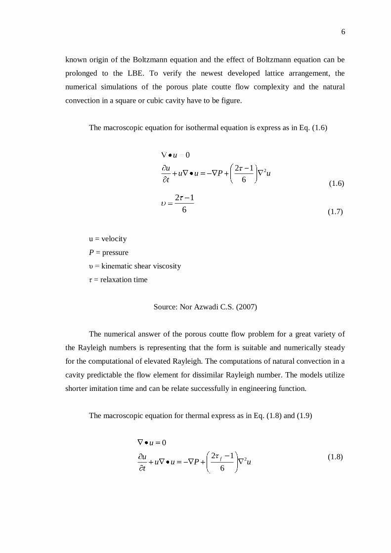
The macroscopic equation for isothermal equation is express as in Eq. (1.6)
uPuut
u
u
2
6
12
0
(1.6)
6
12
(1.7)
u = velocity
P = pressure
υ = kinematic shear viscosity
τ = relaxation time
Source: Nor Azwadi C.S. (2007)
The numerical answer of the porous coutte flow problem for a great variety of
the Rayleigh numbers is representing that the form is suitable and numerically steady
for the computational of elevated Rayleigh. The computations of natural convection in a
cavity predictable the flow element for dissimilar Rayleigh number. The models utilize
shorter imitation time and can be relate successfully in engineering function.
The macroscopic equation for thermal express as in Eq. (1.8) and (1.9)
uPuut
u
u
f 2
6
12
0
(1.8)

7
TTt
Tg
2
2
1u (1.9)
2
13f (1.10)
2
1g
(1.11)
u = velocity
P = pressure
= kinematic shear viscosity
τ = relaxation time
Source: H.N. Dixit and V. Babu (2006)
1.4 PROJECT FLOW CHART
The figure 1.2 shows the project flow chart which is basically referred to the
theory of lattice Boltzmann method. The theory of lattice Boltzmann contained the
governing equation, basic principle of lattice Boltzmann, Collide Function of BGK,
Equilibrium Distribution Function, Time Relaxation, Discretization of Microscopic
Velocity and the Derivation of Navier Stoke Equation. After the theory of lattice
Boltzmann has been studied, the isothermal fluid flow is simulated. The isothermal fluid
flows have two basic flows which is the flow in pipe or the Poiseuille flow and the
Couette flow. The extension of lattice Boltzmann model is the thermal lattice
Boltzmann theory and the Porous Couette flow is simulated. The final part of the flow
chart is to do the main project that is to study the Heated Cylinder Geometry and
Boundary Condition Analysis

8
Figure 1.2: Project flow chart
Theory of Lattice Boltzmann
1. Governing Equation
2. Basic Principle
3. Collide Function BGK
4. Equilibrium Distribution Function
5. Time Relaxation
6. Discretization of Microscopic Velocity
7. Derivation of Navier-Stoke Equation
Isothermal Fluid Flow
1. Simulate flow in pipe
(Poiseuille flow)
2. Simulate Couette flow
Extension to Lattice Boltzmann Model
1. Theory of Thermal Lattice Boltzmann Model
2. Simulate Porous Couette Flow
Heated Cylinder Geometry and Boundary
Condition Analysis
CHAPTER 2
LITERATURE REVIEW
2.1 NAVIER STOKE EQUATION
In the last few years we have seen a quick growth of latest numerical methods
for the result of partial differential equations, especially Navier-Stokes equations. The
history of the Navier–Stokes equations is it named after Claude-Louis Navier and
George Gabriel Stokes. Navier-Stokes equations explain the motion of fluid material
that is material which can flow. These equations obtained from relate Newton's second
law to fluid movement and collectively with the statement that the fluid pressure is the
sum of a spread viscous expression, plus a pressure expression (Batchelor, G.K., 1967).
They are one of the mainly practical sets of equations because they explain the physics
of a large number of phenomena of academic and economic attention. The application is
the weather, ocean currents, water stream in a pipe, flow about an airfoil and movement
of stars within a galaxy. These equations in together complete and shorten outline are
employed in the design of airplane and vehicle, the learning of blood stream, the devise
of power post and the investigation of the effect of pollution.
In a purely mathematical sense, the Navier–Stokes equations are in the great
attention. On the other hand, mathematicians have not yet confirm that in three
dimensions answers always subsist or that if they do subsist they do not include any
infinities, singularities or discontinuities (Batchelor, G.K., 1967). These are known the
Navier–Stokes continuation and smoothness troubles. The Clay Mathematics Institute
has known this one of the seven mainly significant open questions in mathematics. The
Navier–Stokes equations are differential equations which do not explicitly create a
relation between the variables of concern example like velocity and pressure. They
10
establish relations among the rates of change. The Navier–Stokes equations for simple
case of an ideal fluid can affirm that acceleration is proportional to the gradient of
pressure. It also states not position but rather velocity (Frisch, U., Hasslacher, B. and
Pomeau, Y. 1986). A result of the Navier–Stokes equations is called a velocity field or
flow field, which is a description of the velocity of the fluid at a given point in space
and time. Once the velocity field is resolved for, other amount of concern such as flow
rate or drag force may be establish. This is dissimilar from what one normally sees in
classical mechanics, where answers are typically trajectories of position of a particle or
deflection of a continuum. Studying velocity as an alternative of position makes more
sense for a fluid but for visualization reasons one can compute a variety of trajectories.
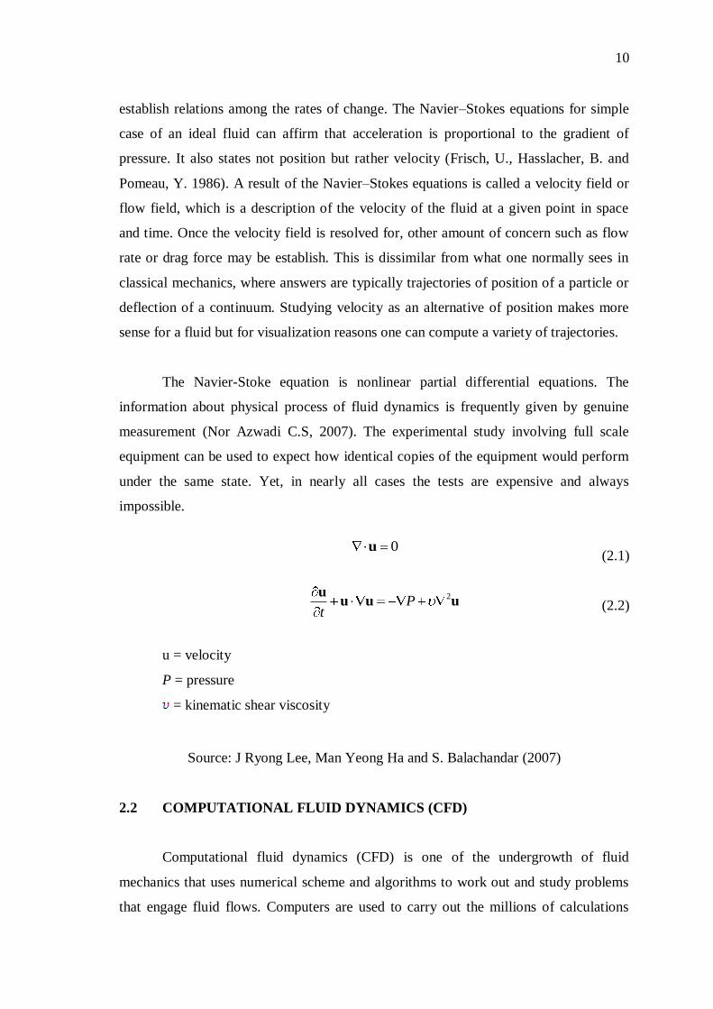
The Navier-Stoke equation is nonlinear partial differential equations. The
information about physical process of fluid dynamics is frequently given by genuine
measurement (Nor Azwadi C.S, 2007). The experimental study involving full scale
equipment can be used to expect how identical copies of the equipment would perform
under the same state. Yet, in nearly all cases the tests are expensive and always
impossible.
(2.1)
(2.2)
u = velocity
P = pressure
= kinematic shear viscosity
Source: J Ryong Lee, Man Yeong Ha and S. Balachandar (2007)
2.2 COMPUTATIONAL FLUID DYNAMICS (CFD)
Computational fluid dynamics (CFD) is one of the undergrowth of fluid
mechanics that uses numerical scheme and algorithms to work out and study problems
that engage fluid flows. Computers are used to carry out the millions of calculations
0u
uuuu 2Pt
11
needed to simulate the relations of fluids and gases with the not easy surfaces used in
engineering. Still with high-speed supercomputers barely inexact solutions can be attain
in many cases. Continuing study, on the other hand, may give way software that give
betters accuracy and speed of difficult simulation situations such as transonic or
turbulent flows (Acheson, D. J., 1990). Software is frequently carried out by a wind
tunnel with the final justification coming in flight analysis. The basic of CFD problem is
the Navier-Stokes equations, which describe whichever single-phase fluid flow. Navier-
Stokes equations can be simplified by eliminate terms explaining viscosity to give in the
Euler equations (Batchelor, G.K., 1967). Advance simplification, by eliminate terms
explaining vorticity give in the complete possible equations. Finally, these equations
can be linearized to give in the linearized possible equations.
In these days, CFD has developed from a mathematical attention to become
significant instrument in solving Navier-Stoke equation and the continuity equation. It is
the science of determining numerical answer of the governing equation of fluid flow
during proceeds the solution through space or time to achieve a numerical explanation
of the whole flow field of attention (Acheson, D. J., 1990). For the fact, numerical
researcher must select a method to discretise the difficulty. The settings up of the
numerical simulation initiate with built a computational grid. The flow variables are
calculated at the node point of this grid in some approach and at in-between points. The
spacing between grid points has to be very well sufficient to achieve a high enough
degree of precision. There are some benefits but to remain the number of grid point
small since of additional grid point indicate more computer memory needed and a
greater time is desired to carry out each iteration of the calculation (Nor Azwadi C.S,
2007). The uncomplicated computational grid rectangular lattice by unchanging spacing
between node points in every dimension. There are series of way that use unstructured
grids where the density of the node point is not constant and is higher in the area where
the precision is wanted. Unstructured meshes often end up being connected in a
triangular or tetrahedral style since these form fill space well and they needed least
number of vertices. Several way employ adaptive meshes where the node point are
generated and devastated as flow featured shift though the computational domain. This
will remain number of nodes to a least but still providing the wanted dimension for the
certain flow elements.