heatshield for extreme entry environment technology (heeet
TRANSCRIPT

1
Heatshield for Extreme Entry Environment Technology (HEEET) Thermal Protection System (TPS)Presented by Matt GaschMS&T19 Technical Meeting and Exhibition, 9/29 – 10/3/2019, Portland OR

HEEET TeamNASA ARC:• Dave Driver (Retired)• Marianne Shelley (Retired)• Ron Chinnapongse (Retired)• Don Ellerby• Matt Gasch• Cole Kazemba• Milad Mahzari• Frank Milos• Owen Nishioka• Keith Peterson• Margaret Stackpoole• Ethiraj Venkatapathy• Zion Young• Peter Gage• Tane Boghozian• Jose Chavez-garcia• Greg Gonzales• Ben Libben• Ruth Miller• Grant Palmer• Dinesh Prabhu• Joseph Williams• Alexander Murphy 2
NASA JSC:• Mike Fowler• Charles Kellermann
NASA LaRC:• Carl Poteet• Scott Splinter• Sarah Langston• Kevin Mclain• Gregory Shanks• Jacob Tury• Stewart Walker• Kelvin G. Boston• Joshua S. Beverly• Elora K. Frye• Wayne D. Geouge• Joseph J. O’Connell• Teresa L. O’Neil• Mark Thornblom• Kevin L. Bloxom• Dwight L. Duncan• William M. Johnston• Louise O’Donnell• Mark C. Roth
External Partners:• Bally Ribbon Mills• Fiber Materials Inc.
External Test Facilities:• Laser Hardened Materials
Evaluation Laboratory (LHMEL)
• Arnold Engineering Development Center (AEDC)
• NTSExternal NDE:• Hadland• NSI• VJ Technologies
Carrier Structures:• AASC
NASA Facilities:• Ames:
• Arcjet Complex• STAR Lab• EEL• Main Shop
• JSC:• ES4/Manufacturing
• LaRC• James H. Starnes, Jr.,
Structures and Materials Laboratory
• Light Alloy Lab• Materials Research Lab• Model Shop• Systems Integration and
Test Branch Laboratory
HEEET Independent Review Board (IRB)• Bobby Braun (UC-Boulder, IRB
Chair)• Micheal Amato (GSFC)• Stan Bouslog (JSC)• Robin Beck (ARC)• Anthony Calomino (LaRC)• Steve Gayle (LaRC)• Ken Hibbard (APL)• Pam Hoffman (JPL)• Joy Huff (KSC)• Michelle Munk (LaRC)• Christine Szalai (JPL)

Outline
• HEEET = Heatshield for Extreme Entry Environment Technology • Motivation for HEEET
• Implementation (2014 – 2019)‒ Requirements‒ Manufacturing ‒ Aerothermal ‒ Structural
• Documentation‒ Design Data Book
• Final TRL Assessment
• Mission Infusion
3

Motivation for HEEET
• Address a shortfall in available TPS to meet NASA’s needs for planetary science missions with very high heating entry environments
• Desire to develop a system that would avoid some of the sustainability challenges related to “heritage” TPS (i.e. Carbon Phenolic)
4
TPS GAP

What is the HEEET Material?
Mid-density 3D woven dual layer carbon phenolic • 3D layer to layer weave
• Dual Layer:
‒ OML Layer = Recession Layer (RL) – manages recession
– Higher density all carbon fiber weave, exposed to entry environment
‒ IML Layer = Insulation Layer (IL) – manages heat load
– Lower density, lower thermal conductivity, blended carbon/phenolic yarn
‒ 2 layers are integrally woven together, – mechanically interlocked (not bonded)
• Woven material has medium density phenolic resin infusion
‒ Higher phenolic loading than PICA
‒ Open porosity
5
Dual Layer Weave
3D Weave

Project Objectives Formulation Process
• Draft set of generic high level TPS requirements sent out for review:‒ Developed with in-put from discipline experts within NASA, including folks who have supported MSL and MPCV
• Assumption is that generally any TPS system is exposed to a common set of environments and that it’s the magnitude of any loads induced by those environments that varies with the mission and point design:‒ Ground‒ Launch‒ Transit (On-orbit)‒ Entry
• Requirements provide a structure to discuss with mission proposing organizations our scope of work and progress towards achieving TRL 6• Requirements are developed from a mission performance perspective• Verification written as a project technology development goal
• Reviewed requirements during HEEET Workshop (7/30/13)‒ Received feedback from Gov’t (APL, JPL, GSFC,…), Industry (LM, Boeing,…)‒ Identified In-Scope Requirements for HEEET‒ Identified verification approach and TRL achieved
6

Seams in the HEEET Architecture
7
• Target vehicle sizes range from <1m – >3.5m base diameter• A tiled heatshield design is required due to weaving width limitations
• Results in seams between tiles – the most challenging part of HEEET development
• The HEEET project has baselined a gap filler between tiles to perform two primary functions:‒ Provide structural relief for all load cases by increasing compliance in the joint‒ Provide an aerothermally robust joint
• Two factors inherent to the HEEET material and its mission applications drive requirements at the seams in the system. ‒ Aerothermal environments for HEEET mission architectures require unsupported
adhesive joint widths be minimized to prevent runaway failure at the seam – IHF 3” nozzle testing at ~3500 W/cm2 and 5 atm suggest joints ≤ 0.010” are
required‒ HEEET in-plane modulus is high
– As the carrier structure deflects the HEEET architecture must have sufficient compliance to maintain compatibility with the carrier without inducing excessive stress in the system
Gap Filler

HEEET Failure Modes
8
Typical failure modes of tiled systems include:• Tile and gap-filler failure
‒ Through Thickness cracks causing “heat leaks”‒ In plane cracks causing reduced thickness‒ Surface erosion (mechanical failure causing spallation or accelerated layer loss)‒ Flowthrough (permeability permits interior flow)
• Loss of attachment of tiles or gap fillers, causing complete loss of thermal material over the full tile area‒ Adhesive mechanical failure
– Substrate failure adjacent to adhesive‒ Adhesive thermal failure
• Cracking and opening of seams, permitting a “heat leak” in the gaps between tiles‒ Adhesive mechanical failure
– Tile failure adjacent to adhesive‒ Adhesive char and erosion
• Material response prediction error‒ Recession rate error
– Differential recession at seam‒ Conduction
StructuralAero/Material

HEEET Manufacturing Overview
9
NASA ARC
Tile Infusion
ESH Infusion
Dry Woven HEEET
Forming
HEEET Softening Process
MachiningCutting
Bally Ribbon Mills
Fiber Materials Inc.(Development)
Nose Cap Path Finder
Softened HEEET Test Articles
Structural Test Coupon Tiles: 4-Point Bend & TTT
Flat Panel Infusion Rough Cutting
MDU & ESH Tile Set
ETU & ESH Tile Set
ArcJet Test Coupons & Misc. Structural Testing
NASA ARC(During Development)
Nose Cap InfusionFormingNose Cap
Cutting
NASA – Johnson Space Center (JSC)
Integration
Tile & Seam Test Coupon Set
Manufacturing Demonstration Unit (MDU)
Engineering Test Unit (ETU)
NASA – Langley Research Center (LaRC)
Test Program
Coupon/Material Testing
ETU Testing
Applied Aerospace Structures Co. (AASC)
Material Procurement
Ply Design
Tooling Design
Layup/Cure/Assembly
AASC Deliverables
4-Point Bend Substrate
TTT Substrate
Carrier Structure 1
Carrier Structure 2
NDT

BRM Weaving
10
• 2 Phase scale up in weaving capability‒ Phase 1: From 1” thickness x 6” width to 2.1” thickness x 13” width‒ Phase 2: Increased width to 24” (2.1” thickness)
Fiber Manufacturing (Raw Materials)
Blended Yarn(Insulation Layer)
Carbon Fiber(Recession Layer)
Tile Infusion
Gap Filler Infusion
Weaving Forming Gap Filler Softening Process
MachiningHEEET TPS
Assembly & IntegrationCutting
Dual Layer HEEET Weave
24” Loom
CT Scan HEEET Weave

FMI Acreage Tile and Gap Filler Manufacturing
• Forming, resin infusion and machining processes were initially developed in-house• Established processes were Tech Transferred to Fiber Materials Inc. (FMI)• FMI performed an upgrade to Infusion Vessel to support HEEET infusion process• FMI successfully fabricated acreage tiles and gap fillers for the ETU
Forming Resin Infusion: Tooling Infused Part Machined Part
Fiber Manufacturing (Raw Materials)
Blended Yarn(Insulation Layer)
Stretch Break / Carding Blending
Carbon Fiber(Recession Layer) Tile Infusion
Gap Filler Infusion
Weaving Forming
Gap Filler Softening Process
MachiningHEEET TPS
Assembly & IntegrationCutting
11

HEEET Drawings/Tooling/GSE/Carrier Structures
12
• 2 composite carrier structures built
• >25 ETU related GSE/Tooling Built
• 100+ ETU related drawing sheets
• >15 manufacturing/integration specifications released
ESH Compression Tooling
Assembly Routing Vacuum Fixture
Inner Tile Vacuum Fixture
Integration Fixture
Routing Fixture
Integration Build StandComposite Carrier Structures

1m ETU Successfully Built and Inspected by CT Scan
13
Gap Filler
Closeout Plug

Arcjet Test Campaign
14
2500
2000
1500
1000
500
0
Tem
pera
ture
, K
4003002001000
Time, s
IHF-319 Low data (2 runs) TITAN nominal
Tw
TC1
TC2
TC3
TC4
TC5
Objectives for aerothermal test campaign:1. Support development and validation of the
TPS sizing tools2. Exercise the system (acreage and seams)
under mission relevant conditions to establish system capability• Looking for failure modes
• 12 arcjet test series conducted• >140 coupons tested• First testing in the IHF 3” nozzle
• 3500 W/cm2 and 5.3 atm• First NASA testing in AEDC H3 facility
• 4000 Pa shear• FIAT code adapted to support dual layer TPS
sizing• Novel dual layer margins policy developed IHF 3”:
Hot Wall Heat Flux: 3600 W/cm2
Pressure: 5.3 atmAEDC Shear Testing:Hot Wall Heat Flux: 1200 W/cm2
Pressure: 2.9 atmShear: ~4000Pa

HEEET Arcjet Testing Covers Some Mission Options for All Target Destinations
15
Limits in ground based test facilities to achieve relevant conditions for some steep and high latitude entries. This issue applies to any TPS concept, not just HEEET.
OrionMSL
Unpredicted Material
Response

Dual Layer TPS Sizing
16
• TPS sizing is the process for determining the thickness of the TPS
• Bondline is the interface between the inner surface of the TPS (IML) and the structure to which it is typically adhesively bonded
• For single layer TPS the constraint is not to allow the bondline, to exceed temperature limit of adhesive or structure
Shoulder
Stag Pt.
Mid-Flank
Size RL and IL Independently
Size IL after Fixing RL to Max Thickness
Final Thickness
Final Thickness
• Dual Layer TPS introduces a new constraint, not to allow the insulation layer to be exposed
• Current HEEET implementation requires uniform TPS thickness for both layers
• Max thickness for each layer may occur at different body points and trajectories
• Sizing RL and IL independently and then stacking max RL thickness from one location on max IL thickness from another location is not mass efficient‒ Excess RL at some locations can serve as insulation
• More mass efficient to size IL after fixing RL to max sized thickness across all locations

Example Sizing from a
Venus Reference Mission
17
Sizing done at 9 locations on the heatshield• Figure on left: RL and IL sized independently
• Figure on right: RL sized first; then IL sized while for fixed RL thickness
Taking advantage of the nonessential portion of RL thickness at locations that don’t drive RL sizing provides mass benefits • 62% reduction in IL thickness, 19% reduction in areal mass
Stag Sph1 Sph2 Junction Flank1 Flank2 Flank3 Flank4 Shoulder
0.6
0.4
0.2
0
0.2
0.4
0.6
RL T
hick
ness
(in)
IL T
hick
ness
(in)
Max RL Thickness
Max IL Thickness
RL and IL Sized Independently (Not taking advantage of excess RL)
IL Sized after Fixing RL to Max Thickness(Taking advantage of excess RL)
Final Thickness
Stag Sph1 Sph2 Junction Flank1 Flank2 Flank3 Flank4 Shoulder
0.6
0.4
0.2
0
0.2
0.4
0.6
Required IL Thickness
Required RL Thickness
Excess RL Thickness
Required IL ThicknessRequired RL ThicknessExcess RL Thicknessdata2data1
*Sizing and Margin Methodology for Dual-Layer Thermal Protection Systems, Mahzari and Milos, 15th International Planetary Probe Workshop
3.5
m
Body Point 1(Stag. point)
Body Point 9(Shoulder)

Structural Test Campaign
• Element Level Testing• Material Properties and allowables
• Different Layers• Gap Filler• Adhesives• Composite structure
• Component Level Testing• 4-pt Bend (LaRC)• LHMEL 4pt-Bend
• Developed novel test approach• Adopted by Orion
• Shock Testing (NTS)
• Subsystem Testing (LaRC)• 1m Engineering Test Uniut (ETU)
18
Post Test
Actuator
Moving Frame
Fixed Frame Laser
Specimen
Load Application Apparatus
Schematic of LHMEL Structural Panel Test
LOAD LOAD
LOAD LOAD
LASERN2N2
HEEET
CompositeGapfiller
4-Pt Flexure Rig
Specimen
Load ArmBall Joint attaches
hereI-beam
I-beamRigid
Attachment
Shock Testing

Subsystem (ETU) Testing Overview
19
Static Point Load (Rd1)
Thermal-Vacuum
Static Point Load (Rd2)
MDU Carrier Structure Proof TestETU Carrier Structure Proof Test
Pre-Integration
Integrate TPS on Carrier Structure
NDE(CT)
NDE
Static Pressure
NDE
NDE(CT)
NDE
79 Total Strain GagesFor Test:
• 24 Biaxial‒ 17 on Recession layer‒ 7 on Composite
• 17 Uniaxial‒ 14 on Composite‒ 3 on Ring
For Defect Tracking: 14 Uniaxial
Static Pressure Test in Autoclave
Static Point Load Configuration
ETU in Thermal Vac Chamber
Point Load Locations
12 load locations are shown23 total tests, 2 at each location minus nosecap
Pt 12: Under Closeout Plug
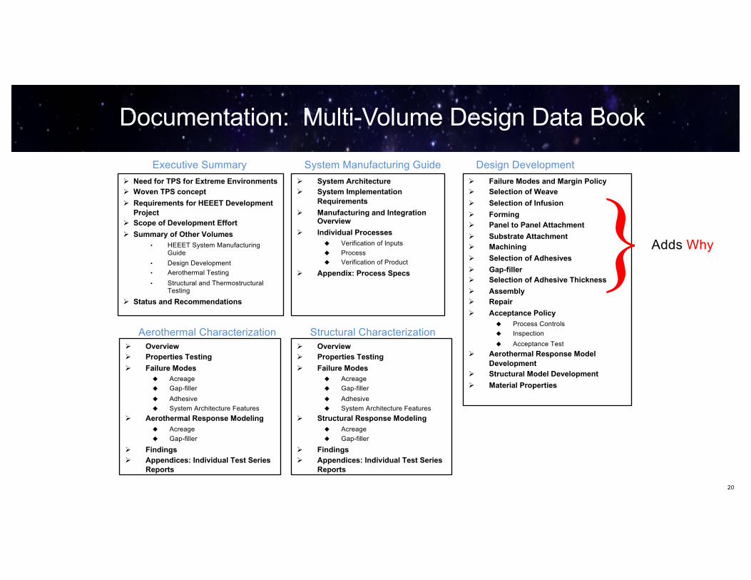
Documentation: Multi-Volume Design Data Book
Ø System ArchitectureØ System Implementation
RequirementsØ Manufacturing and Integration
OverviewØ Individual Processes
u Verification of Inputs
u Process
u Verification of Product
Ø Appendix: Process Specs
Executive Summary System Manufacturing Guide
Ø Failure Modes and Margin PolicyØ Selection of WeaveØ Selection of InfusionØ FormingØ Panel to Panel AttachmentØ Substrate AttachmentØ MachiningØ Selection of AdhesivesØ Gap-fillerØ Selection of Adhesive ThicknessØ AssemblyØ RepairØ Acceptance Policy
u Process Controls
u Inspection
u Acceptance Test
Ø Aerothermal Response Model Development
Ø Structural Model DevelopmentØ Material Properties
Design Development
Ø OverviewØ Properties TestingØ Failure Modes
u Acreage
u Gap-filler
u Adhesive
u System Architecture Features
Ø Aerothermal Response Modelingu Acreage
u Gap-filler
Ø FindingsØ Appendices: Individual Test Series
Reports
Aerothermal CharacterizationØ OverviewØ Properties TestingØ Failure Modes
u Acreage
u Gap-filler
u Adhesive
u System Architecture Features
Ø Structural Response Modelingu Acreage
u Gap-filler
Ø FindingsØ Appendices: Individual Test Series
Reports
Structural Characterization
} Adds Why
Ø Need for TPS for Extreme EnvironmentsØ Woven TPS conceptØ Requirements for HEEET Development
ProjectØ Scope of Development EffortØ Summary of Other Volumes
• HEEET System Manufacturing Guide
• Design Development
• Aerothermal Testing
• Structural and ThermostructuralTesting
Ø Status and Recommendations
20

What is Technology Readiness Level (TRL) and Why is it Important?
TRL is a way that NASA assesses the readiness of a new technology for infusion into a mission.TRL Levels:• TRL 1 Basic principles observed and reported
• TRL 2 Technology concept and/or application formulated
• TRL 3 Analytical and experimental critical function and/or characteristic proof of concept
• TRL 4 Component/subsystem validation in laboratory environment
• TRL 5 System/subsystem/component validation in relevant environment
• TRL 6 System/subsystem model or prototyping demonstration in a relevant end-to-end environment (ground or space)• TRL 7 System prototyping demonstration in an operational environment (ground or space)
• TRL 8 Actual system completed and "mission qualified" through test and demonstration in an operational environment (ground or space)
• TRL 9 Actual system "mission proven" through successful mission operations (ground or space)
Why is TRL 6 important for HEEET?• Primary missions HEEET is targeted for are NASA Science Mission Directorate entry probe missions to other
planets (ex. Venus, Saturn, Neptune, Uranus)
• Missions are often competitively selected (ex. Discovery and New Frontiers Announcement of Opportunities)
• New technologies in such proposals are required to be at TRL 6 by Preliminary Design Review (PDR)
• If HEEET at TRL 6 it is easier to infuse into proposals (mission is not burdened with cost of maturing technology) 21
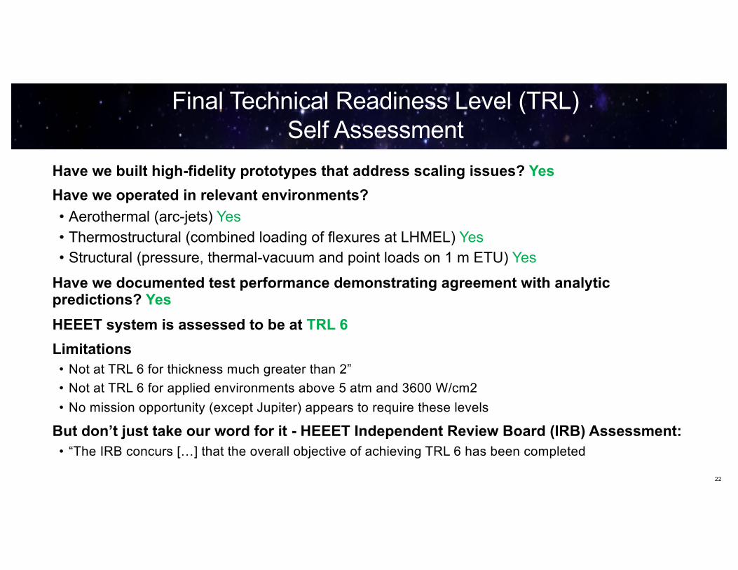
Final Technical Readiness Level (TRL) Self Assessment
Have we built high-fidelity prototypes that address scaling issues? Yes
Have we operated in relevant environments?
• Aerothermal (arc-jets) Yes• Thermostructural (combined loading of flexures at LHMEL) Yes• Structural (pressure, thermal-vacuum and point loads on 1 m ETU) Yes
Have we documented test performance demonstrating agreement with analytic predictions? Yes
HEEET system is assessed to be at TRL 6
Limitations• Not at TRL 6 for thickness much greater than 2”• Not at TRL 6 for applied environments above 5 atm and 3600 W/cm2• No mission opportunity (except Jupiter) appears to require these levels
But don’t just take our word for it - HEEET Independent Review Board (IRB) Assessment:• “The IRB concurs […] that the overall objective of achieving TRL 6 has been completed
22

3D Woven Thermal Protection System (TPS) Development
23
Enabling Orion with Lunar Capable Compression Pad
May
, 201
9
23• 3D-MAT is tailoring a specific Woven TPS solution for the Orion compression pad for the 2018 Lunar Flight (EM-1)
• HEEET has been matured to TRL 6 and is ready for mission infusion.
Mar
ch 2
011
Woven TPS GCT BAA
Jan.
201
2
June
, 201
2
3D Woven Multifunctional Ablative TPS (3D-MAT)
Heat-shield for Extreme Entry Environment Technology
(HEEET)
Oct
, 201
3
2028 - 2032Tech. Maturation to enable Venus, Saturn and outer
planets missions
Discovery and NF-4AO Incentivized
Under Consideration as Heat-shield for Mars
Sample Return Mission
2026
EM-1
Woven TPSCIF
Venus, Saturn and Ice Giant Missions
HEEET ID’edas NASA developed new technology in Discovery 2019 AO

Any Questions?
24