hfs 3 8/22/12...ment. if buyer received defective goods or parts, buyer may send such defective...
TRANSCRIPT
HFS 38/22/12
GF HARVEL CPVC FIRE SPRINKLER PIPING PRODUCTS
Georg Fischer Harvel LLC. (“Seller” or “HARVEL”) warrants that the goods covered by this Warranty shall be free from defects in materials and workmanship for a period of ten (10) years from the date of ship-ment. If Buyer received defective goods or parts, Buyer may send such defective goods or parts prepaid to Seller’s Easton, PA facility accompa-nied by a letter stating the nature of the defect(s). After examination, if there is determined to be a defect in materials or workmanship (of GF Harvel), Seller at its option may repair or replace the defective part(s), or Seller may reimburse Buyer for the cost of such part(s). This is Buyer’s only remedy. All costs of shipping the defective parts and their replace-ments to and from Seller’s facility at Easton, shall be borne by Buyer. Buyer agrees that Seller will not be responsible for other parts or labor in connection with repairing, replacing, or returning such goods or parts (while goods are in possession of Seller for analysis), nor for delays beyond Seller’s reasonable control (including, without limitation, delays due to fire, flood, accident, strike, governmental regulation or other acts of God), provided that any delay shall toll the warranty period for the same amount of time as the delay itself.
Buyer agrees that this Warranty shall be for ten (10) years, so long as the goods shall be given normal usage and operated in conformance with Seller’s recommendations and its operating and maintenance instructions. Violation thereof shall void this warranty and relieve Seller from any obli-gation under this warranty.
Since performance and production figures, if given, are Seller’s best estimates based on its understanding of tooling, molding materials, accessory and other factors not all of which are within Seller’s control. Seller cannot and does not assume responsibility, and expressly disclaims any liability, for failure of the goods to meet such estimates.
GF Harvel EXTENDS ONLY THIS WARRANTY. BUYER SPECIFICALLY WAIVES OTHER WARRANTIES. EXPRESSED OR IMPLIED, ORAL OR STATUTORY (INCLUDING ANY IMPLIED WARRANTIES OR MERCHANTABILITY OR OF FITNESS FOR A PARTICULAR PURPOSE), APPLICABLE TO THE GOODS OR TO SELLER.
BUYER SPECIFICALLY AND EXPRESSLY WAIVES SELLER’S LIABILITY OR OBLIGATION OF ANY KIND OR CHARACTER, INCLUDING WITHOUT LIMITATION LIABILITY PREDICATED UPON STRICT LIABILITY OR TORT, OR INCLUDING ANY OBLIGATION OR LIABILITY FOR INCIDENTAL, CONSEQUENTIAL OR SPECIAL DAMAGES ARISING OUT OF OR WITH RESPECT TO THE GOODS, THEIR SALE OR OPERATION OR THE REPAID, REPLACEMENT OR RETURN OF ANY PART THEREOF.
In the event of the bringing of any legal action by the customer against GEORG FISCHER HARVEL LLC arising herein or hereunder then the party in whose favor the final judgment shall be entered, shall be entitled to have and recover from the other, reasonable attorneys fees and costs incurred, to be fixed by the courts wherein such judgment is entered.
THIS WARRANTY MAY NOT BE EXTENDED, ALTERED OR OTHERWISE MODIFIED EXCEPT BY WRITTEN INSTRUMENT SIGNED BY SELLER.
GENERAL INFORMATION ...............................................................................................4Training ...............................................................................................................................4Advantages .........................................................................................................................4
TECHNICAL DATA ............................................................................................................5Product Ratings and Capabilities .......................................................................................5Hydraulic Design ................................................................................................................5Ambient Temperature Limitations ....................................................................................6Chemical Compatibility .......................................................................................................6Painting of Pipe ..................................................................................................................8Thermal Expansion .............................................................................................................8Proximity to Heat Sources .................................................................................................9
WHERE TO USE A GF HARVEL CPVC FIRE SPRINKLERSYSTEM (Listings and Approvals) ................................................................................10Return Air Plenums .........................................................................................................10Concealed Installations .....................................................................................................11Exposed Installations .......................................................................................................11 Standard Coverage and Residential Sprinklers ............................................................11 Light Hazard Extended Coverage and Residential Sprinklers ......................................12 Unfinished Basements with Exposed Composite Wood Joists in accordance with NFPA 13D ...............................................................................13 Unfinished Basements per NFPA 13D ....................................................................15 Exposed System Risers Per NFPA 13, 13D and 13R ..................................................18Combustible Concealed Installation with Specific Use Sprinklers ...................................18Combustible Attic Spaces with Specific Use Sprinklers ..................................................19System Risers Per NFPA 13, 13D and 13R ....................................................................19Garages Per NFPA 13R ...................................................................................................21Underground Fire Service ...............................................................................................22Ordinary Hazard Installations ............................................................................................24C-UL Listing Requirements .............................................................................................25Dry Pipe Application .........................................................................................................26Factory Mutual (FM) ........................................................................................................27
INSTALLATION ..............................................................................................................30Handling and Storage ......................................................................................................30Transition to Other Materials ...........................................................................................30 Threaded Connections .................................................................................................30 Flanged Connections ...................................................................................................32 Grooved Coupling Adapters .........................................................................................33 with Listed Shurjoint® Rubber Gasketed Couplings and Grooved End Fittings ........35 Adjustable Sprinkler Head Adapter ..............................................................................41Solvent Cementing Procedures ......................................................................................42Hydrostatic Pressure Testing ..........................................................................................48Hangers and Supports .....................................................................................................50Fire Rated Walls and Partitions ........................................................................................54Freeze Protection .............................................................................................................54Other Design Criteria ......................................................................................................55Cut-In Procedures for System Modification or Repairs ...................................................56
DOs AND DON’Ts OF INSTALLATION ..........................................................................58
REFERENCE TABLES .....................................................................................................60Modulus of Elasticity & Stress vs. Temperature .............................................................60Physical & Thermal Properties ........................................................................................60Thermal Expansion ..........................................................................................................62Expansion Loop Length ...................................................................................................63Expansion Loop & Offset Configurations ........................................................................64Bending Deflections .......................................................................................................66Snaking Deflections .........................................................................................................67
APPENDIXES ..................................................................................................................68Appendix A ......................................................................................................................68Appendix B ......................................................................................................................70Appendix C ......................................................................................................................72
CONTRACTOR RESOURCES .........................................................................................75Job Site Label ...................................................................................................................75Care and Maintenance Document ...................................................................................77
SAFETY ALERT MESSAGES ..........................................................................................79
Warranty Table of Contents
5
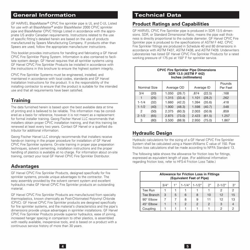
Product Ratings and CapabilitiesGF HARVEL CPVC Fire Sprinkler pipe is produced in SDR 13.5 dimen-sions. SDR, or Standard Dimensional Ratio, means the pipe wall thick-ness is directly proportional to the outside diameter. GF Harvel CPVC Fire Sprinkler pipe is produced to the specifications of ASTM F 442. CPVC Fire Sprinkler fittings are produced in Schedule 40 and 80 dimensions in accordance with ASTM F437, ASTM F438, and ASTM F439. Underwriters Laboratories has listed GF Harvel CPVC Fire Sprinkler Products for a rated working pressure of 175 psi at 150° F for sprinkler service.
4
GF HARVEL BlazeMaster® CPVC fire sprinkler pipe is UL and C-UL Listed for use with all BlazeMaster® and/or BlazeMaster 2000 CPVC sprinkler pipe and BlazeMaster CPVC fittings Listed in accordance with the appro-priate US and/or Canadian requirements. Instructions related to the use of specific fitting’s detailed herein are based on the use of products manufactured by Spears Manufacturing Company. If products other than Spears are used, follow the appropriate manufacturer instructions.
This booklet provides instructions for handling and fabricating a GF Harvel CPVC Fire Sprinkler Piping System. Information is also contained to facili-tate system design. GF Harvel requires that all sprinkler systems using GF Harvel CPVC Fire Sprinkler Products be installed in accordance with the instructions in this brochure to ensure the highest system integrity.
CPVC Fire Sprinkler Systems must be engineered, installed, and maintained in accordance with local codes, standards and GF Harvel Installation Instructions for the product. It is the responsibility of the installing contractor to ensure that the product is suitable for the intended use and that all requirements have been satisfied.
TrainingThe data furnished herein is based upon the best available data at time of printing and is believed to be reliable. This information may be consid-ered as a basis for reference, however it is not meant as a replacement for formal installer training. Georg Fischer Harvel LLC recommends that installers obtain proper CPVC installation training, and that this training be renewed at least every two years. Contact GF Harvel or a qualified dis-tributor for additional information.
Georg Fischer Harvel LLC strongly recommends that installers receive hands-on training in the proper procedure for installation of GF Harvel CPVC Fire Sprinkler systems. On-site training in proper pipe preparation techniques, solvent cementing, installation instructions and the proper handling of plastics is available at no charge. For information about on-site training, contact your local GF Harvel CPVC Fire Sprinkler Distributor.
AdvantagesGF Harvel CPVC Fire Sprinkler Products, designed specifically for fire sprinkler systems, provide unique advantages to the contractor. The easy assembly provided by the solvent cement system and excellent hydraulics make GF Harvel CPVC Fire Sprinkler products an outstanding material.
GF Harvel CPVC Fire Sprinkler Products are manufactured from specialty thermoplastics, known chemically as Post-Chlorinated Polyvinyl Chloride (CPVC). GF Harvel CPVC Fire Sprinkler products are designed specifically for fire sprinkler systems, and the material’s characteristics and the pipe’s dimensions provide unique advantages in sprinkler installations. GF Harvel CPVC Fire Sprinkler Products provide superior hydraulics, ease of joining, increased hanger spacing in comparison to other plastics, is assembled with readily available, inexpensive tools, and is based on a product with a continuous service history of more than 30 years.
Technical Data General Information
Hydraulic DesignHydraulic calculations for the sizing of a GF Harvel CPVC Fire Sprinkler System shall be calculated using a Hazen-Williams C value of 150. Pipe friction loss calculations shall be made according to NFPA Standard 13.
The following table shows the allowance for friction loss for fittings, expressed as equivalent length of pipe. (For additional information regarding friction loss, refer to HFS-4 Friction Loss Table.)
Allowance for Friction Loss in Fittings(Equivalent Feet of Pipe)
Tee RunTee Branch90° Elbow45° ElbowCoupling
13711
15711
16821
18921
1101121
2121232
2151342
3/4" 1" 1-1/4" 1-1/2" 2" 2-1/2" 3"
CPVC Fire Sprinkler Pipe Dimensions SDR 13.5 (ASTM F 442)
Inches (millimeters)
Nominal Size Average OD Average ID PoundsPer Feet
.168
.262
.418
.548
.8591.2571.867
3/41
1-1/41-1/2
22-1/2
3
(20)(25)(32)(40)(50)(65)(80)
1.0501.3151.6601.9002.3752.8753.500
(26.7)(33.4)(42.2)(48.3)(60.3)(73.0)(88.9)
.8741.1011.3941.5982.0032.4232.950
(22.5)(28.2)(35.6)(40.7)(50.9)(61.5)(75.0)
6 7
sprinkler products. Additional chemical compatibility information can be found online at: http://www.harvelsprinklerpipe.com/caution_areas/chemical_compatibility.asp.
CPVC PIPING COMPONENTS MAY BE DAMAGED BY CERTAIN SUBSTANCES USED IN CONSTRUCTION AND BUILDING MAINTENANCE.
ONLY SYSTEM COMPATIBLE MATERIALS INCLUDING, BUT NOT LIMITED TO SOLVENT CEMENTS, CAULKS, SEALANTS, CUTTING OILS AND THREAD PASTES AS NOTED IN HARVEL’S INSTALLATION INSTRUCTIONS SHOULD BE USED IN CONTACT WITH THIS SYSTEM.
DO NOT EXPOSE CPVC PRODUCTS TO INCOMPATIBLE SUBSTANCES SUCH AS CUTTING OILS, NON-WATER BASED PAINTS, PACKING OILS, TRADITIONAL PIPE THREAD PASTE AND DOPE, FUNGICIDES, TERMITICIDES, INSECTICIDES, DETERGENTS, BUILDING CAULKS,
ADHESIVE TAPE, SOLDER FLUX, FLEXIBLE WIRE/CABLE (WITH SPECIAL CONSIDERATION FOR COMMUNICATIONS CABLING), AND NON-APPROVED SPRAY FOAM INSULATION MATERIALS.
DO NOT EXPOSE CPVC PRODUCTS TO EDIBLE OILS, SOLVENTS, OR GLYCOL-BASED ANTI-FREEZE FLUIDS. WHEN COMBINING METALLIC PIPE AND FITTINGS WITH CPVC PRODUCTS IN A SYSTEM, THE CUTTING OILS SHOULD BE REMOVED PRIOR TO ASSEMBLY.
DO NOT STORE CPVC PRODUCTS IN CONTAINERS WITH METAL PRODUCTS WHERE IT MAY BECOME DAMAGED OR CONTAMINATED WITH PACKING OILS.
DO NOT HANDLE CPVC PRODUCTS WITH GLOVES CONTAMINATED WITH OILS (HYDROCARBONS) OR OTHER INCOMPATIBLE MATERIALS.
CERTAIN ANTIMICROBIAL COATINGS CONTAIN ENVIRON-MENTAL STRESS CRACKING AGENTS THAT CAN BE DETRIMENTAL TO CPVC. GEORG FISCHER HARVEL LLC RECOMMENDS THAT ONLY NON-COATED STEEL PIPE BE USED IN CONJUNCTION WITH GF HARVEL BLAZEMASTER CPVC, UNLESS THE ANTIMICROBIAL COATING BEING USED ON THE STEEL PIPE CAN BE DOCUMENTED AS BEING COMPATIBLE WITH CPVC. THE STEEL PIPE MANUFACTURER SHOULD BE CONTACTED TO ENSURE THAT THEIR PRODUCTS ARE COMPATIBLE FOR USE WITH CPVC PRIOR TO USE. IN ADDITION, THE USE OF AFTERMARKET ANTIMICROBIAL COATINGS MUST NOT BE USED TO APPLY TO UNTREATED STEEL PIPE THAT IS USED IN CONJUNCTION WITH CPVC, UNLESS THAT COATING HAS ALSO PROVEN TO BE COMPATIBLE WITH CPVC.
Ambient Temperature LimitationsGF HARVEL CPVC Fire Sprinkler Piping Products are Listed for use in wet pipe systems only, and are not Listed for outdoor use.
GF Harvel CPVC Fire Sprinkler Products are suitable for use in areas where ambient temperatures are within the range of 35°F to 150°F. GF Harvel CPVC Fire Sprinkler pipe can be installed in an area, such as an attic, where the temperature will exceed 150°F if ventilation is provided or if insulation is used around the pipe to maintain a cooler environment. If the installation is in an area subject to freezing temperatures, the sprinkler system must be protected from freezing. A frozen system will not only be deactivated, but the pressures built up can cause the sprinkler heads to open or damage the pipes.
* The LPCB Listing, Part 5, Section 22, Note 2 states that the maximum ambient temperature shall not exceed 120°F.
Chemical CompatibilityGF Harvel CPVC Fire Sprinkler Products resist attack from a wide range of chemicals that are corrosive to metallic piping; CPVC material has been used in many corrosive industrial piping systems for many years due to its inher-ent corrosion resistance. However, in instances where a chemical substance may come into contact with the fire sprinkler system, Georg Fischer Harvel LLC recommends that compatibility with CPVC be confirmed prior to use.
As with any piping material, there are however, certain chemicals that can be detrimental to CPVC. Occasionally some of these chemicals may be found in certain construction products and specific site preparations. CPVC materials can be damaged by contact with chemicals found in some construction and ancillary products such as cutting oils, thread sealants, anti-freeze solutions, fire stop materials, anti-microbial coatings on steel pipe, etc. It is important to verify the compatibility of materials that come in contact with the CPVC sys-tem to ensure long-term performance. Properly designed, installed and cared for, GF Harvel CPVC piping systems will perform without issue and will bring the property owner years of safety and security.
Chemical compatibility information pertaining to CPVC pipe and fittings manufactured from BlazeMaster® CPVC compounds can be found online at http://www.systemcompatible.com. Georg Fischer Harvel LLC strongly recommends that users of GF Harvel BlazeMaster CPVC products visit this website and review the System Compatibility information. The BlazeMaster System Compatibility Program tests and monitors ancillary products on an ongoing basis to ensure chemical compatibility with BlazeMaster CPVC products, and those products that are compatible, carry a compatibility mark to assist the user in identifying acceptable ancillary products. GF Harvel also publishes a chemical resistance guide for our piping products, which can be found online at http://www.harvel.com/tech-support-chem.asp.
ALWAYS CHECK with GF Harvel Technical Services at 610-252-7355 if you have questions regarding chemical compatibility of GF Harvel CPVC fire
8 9
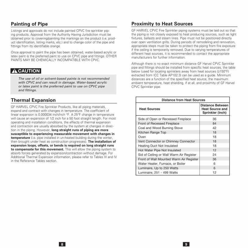
Heat SourcesDistance Between Heat Source and Sprinkler (Inch)
Side of Open or Recessed FireplaceFront of Recessed FireplaceCoal and Wood Burning StoveKitchen Range TopOvenVent Connector or Chimney ConnectorHeating Duct Not InsulatedHot Water Pipe Not InsulatedSid of Ceiling or Wall Warm Air RegisterFront of Wall Mounted Warm Air RegisterWater Heater, Furnace, or BoilerLuminaire, Up to 250 WattsLuminaire, 251 - 499 Watts
368442181818181224366612
Distance from Heat Sources
Painting of PipeListings and approvals do not include painted CPVC fire sprinkler pip-ing products. Approval from the Authority Having Jurisdiction must be obtained prior to covering/painting the markings on the product (i.e. prod-uct identification, listing marks, etc.) and to change color of the pipe and fittings from its identifiable orange
Once approval to paint the pipe has been obtained, water-based acrylic or latex paint is the preferred paint to use on CPVC pipe and fittings. OTHER PAINTS MAY BE CHEMICALLY INCOMPATIBLE WITH CPVC.
The use of oil or solvent-based paints is not recommended with CPVC and can result in damage. Water-based acrylic or latex paint is the preferred paint to use on CPVC pipe and fittings.
Thermal ExpansionGF HARVEL CPVC Fire Sprinkler Products, like all piping materials, expand and contract with changes in temperature. The coefficient of linear expansion is 0.000034 inch/inch °F. A 25°F change in temperature will cause an expansion of 1/2 inch for a 50 foot straight length. For most operating and installation conditions, the effects of thermal expansion and contraction are usually absorbed by the system at changes in direc-tion in the piping. However, long straight runs of piping are more susceptible to experiencing measurable movement with changes in temperature (i.e. pipe installed in un-heated building during the winter, then brought under heat as construction progresses). The installation of expansion loops, offsets, or bends is required on long straight runs to compensate for this movement. This will allow the piping system to absorb forces generated by expansion/contraction without damage. For Additional Thermal Expansion information, please refer to Tables III and IV in the Reference Tables section.
Proximity to Heat SourcesGF HARVEL CPVC Fire Sprinkler piping systems must be laid out so that the piping is not closely exposed to heat producing sources, such as light fixtures, ballasts and steam lines. Pipe must not be positioned directly over open ventilation grills. During periods of remodeling and renovation, appropriate steps must be taken to protect the piping from fire exposure if the ceiling is temporarily removed. Due to varying temperatures of different heat sources, it is recommended to contact the appropriate manufacturers for further information.
Although there is no exact minimum distance GF Harvel CPVC Sprinkler pipe and fittings should be installed from specific heat sources, the table below (used for locating sprinklers away from heat sources (≥150°F) extracted from ICC Table AP102.3) can be used as a guide. Minimum distances are a function of the specified heat source, the maximum ambient temperature, heat shielding, if at all, and proximity of GF Harvel CPVC Sprinkler pipe.
10 11
Concealed InstallationsWith concealed installations, in accordance with the UL Listing, the mini-mum protection shall consist of one layer of 3/8 in. gypsum wallboard, or a suspended membrane ceiling with lay-in panels or tiles having a weight of not less than .35 lbs. per ft2. when installed with metallic support grids, or 1/2 in. plywood soffits. For residential occupancies defined in NFPA 13D and 13R, the minimum protection may consist of one layer of 1/2 in. plywood.
GF Harvel CPVC Fire Sprinkler piping products can be used in sprin-kler systems employing sprinkler heads rated at 225°F or lower when installed concealed (protected) in accordance with the Listing, and the maximum temperature rating (150°F) of the pipe and fittings is not exceeded.
Exposed InstallationsAs an alternative to the minimum protection requirements called out for concealed installations, GF Harvel CPVC Fire Sprinkler Products are UL Listed for systems without protection, (exposed) when subject to the following additional limitations:
Standard Coverage and Residential SprinklersExposed CPVC Fire Sprinkler piping shall be installed below a smooth, flat, horizontal ceiling construction and require the use of FS-5 one step solvent cement.
Pendent Sprinklers Light Hazard or Residential Pendent SprinklersListed quick response, 170°F maximum temperature rated pendent sprinklers having deflectors installed within 8 inches of the ceiling; or, Listed residential, 170°F maximum temperature rated pendent sprin-klers located in accordance with their Listing and a maximum distance between sprinklers not to exceed 15 feet. The piping shall be mounted directly to the ceiling.
GF HARVEL CPVC Fire Sprinkler Products are UL Listed and C-UL Listed by Underwriters Laboratories Inc. for use in:
• Light Hazard occupancies as defined in the Standard for Installation of Sprinkler systems, NFPA 13.
• Residential occupancies up to and including four stories in height as defined by NFPA 13R.
• Residential occupancies as defined in the Standard for Sprinkler Systems in One and Two Family Dwellings, NFPA 13D.
• Installation of private fire service mains and their appurtenances, NFPA 24.
GF Harvel CPVC Fire Sprinkler Products shall be employed in wet pipe systems only (A wet pipe system contains water and is connected to a water supply system so that the water will discharge immediately when the sprinkler is opened.) GF Harvel CPVC fire sprinkler products are not Listed for outdoor use.
AIR OR COMPRESSED GAS MUST NEVER BE USED FOR SYSTEM ACCEPTANCE TESTING (HYDROSTATIC PRESSURE TEST). SYSTEM FAILURE WHEN USING COMPRESSED AIR/GAS FOR SYSTEM ACCEPTANCE CAN RESULT IN BODILY INJURY, DEATH AND/OR PROPERTY DAMAGE
National Fire Protection Association, Standards 13, 13D and 13R must be referenced for design and installation requirements in conjunction with these installation instructions.
Return Air PlenumsGF Harvel CPVC Fire Sprinkler Products are approved for use in air ple-nums. GF Harvel CPVC Fire Sprinkler Products have been investigated by UL per the requirements of UL 1887 and found to comply with the com-bustibility requirements for thermoplastic sprinkler pipe as described in the Standard for Installation of Air Conditioning and Ventilating Systems, NFPA 90A and various model mechanical codes. (Note: GF Harvel CPVC Fire Sprinkler Products may be installed in the plenum adjacent to, but not over, openings in the ceiling such as ventilation grills and require the use of Schedule 80 fittings in the 1-1/2 in. and larger sizes.)
Canadian Installations (ULC & C-UL)GF Harvel CPVC Fire Sprinkler Products are listed under CAN/ULC Standard S102.2M for flame spread of 5, smoke development of 15, and fuel contribution of 0 meeting the National Building Code of Canada.
Where to use a GF Harvel CPVC Fire Sprinkler System (Listings and Approvals)
12 13
Light Hazard Extended Coverage or Residential Horizontal Sidewall Sprinklers
Listed light hazard extended coverage quick response 175°F maximum temperature rated horizontal sidewall sprinklers, having deflectors installed within 12 inches from the ceiling and within 6 inches from the sidewall, a maximum distance between sprinklers not to exceed 16 feet, and an application density not less than 0.10 gpm/ft2.
Listed residential 165°F maximum temperature rated horizontal sidewall sprinklers, having deflectors installed within 12 inches from the ceiling and within 6 inches from the sidewall, a maximum distance between sprinklers not to exceed 18 feet, and an application density not less than 0.10 gpm/ft2.
Listed light hazard extended coverage, quick response, 165°F maxi-mum temperature rated horizontal sidewall sprinklers, having deflectors installed within 12 inches from the ceiling and within 6 inches from the sidewall, a maximum distance between sprinklers not to exceed 18 feet, and an application density not less than 0.10 gpm/ft2.
Listed light hazard extended coverage, quick response, 155°F maxi-mum temperature rated horizontal sidewall sprinklers, manufactured by Reliable Automatic Sprinkler Co. Inc., SIN RA0362) having deflectors installed within 12 inches from the ceiling and within 6 inches from the sidewall, a maximum distance between sprinklers not to exceed 24 feet, and a flow not less than 40 gpm per sprinkler.
Unfinished Basements with Exposed Composite Wood Joists in accordance with NFPA 13D
GF Harvel CPVC fire sprinkler piping products may be installed without protection (exposed) in unfinished basements in accordance with NFPA 13D when subject to the following additional limitations:
1. The ceiling shall be horizontal and constructed utilizing composite wood I-joists with a nominal depth of 11-7/8 inches or less on 24 inch centers.
2. The distance from the floor to the bottom of the composite wood I-joists shall be between 7 feet and 10 feet.
3. Listed residential pendent sprinklers with a maximum temperature rating of 155°F and a minimum K-factor of 4.9 are to be used for this type of installation. The maximum sprinkler spacing shall not exceed 16 feet. The maximum sprinkler coverage area is to be 16 feet by 14 feet spaced with the 16 foot dimension along the joists and the 14 foot dimension across the joists. Lesser areas are also permit-ted. The system is to be designed based upon the Listed flows for the sprinkler selected except that the flow for a single sprinkler or for multiple sprinklers flowing is to be not less than 13 gpm per sprinkler. The sprinklers are to be installed with their deflectors a maximum of 1-3/4 inches below the bottom of the composite wood I-joists in anticipation of future installation of a finished ceiling. (reference NFPA 13D, Section 8.2.4, 2010 Edition)
Sidewall Sprinklers Light Hazard or Residential Horizontal Sidewall Sprinklers
Listed quick response, 170°F maximum temperature rated horizontal sidewall sprinklers having deflectors installed within 6 inches from the ceiling and within 4 inches from the sidewall; or, Listed residential 170°F maximum temperature rated horizontal sidewall sprinklers locat-ed in accordance with their Listing and a maximum distance between sprinklers not to exceed 14 feet. The piping shall be mounted directly to the sidewall.
Listed quick response 200°F maximum temperature rated horizontal sidewall sprinklers having deflectors installed within 12 inches from the ceiling and within 6 inches from the sidewall; or, Listed residential 200°F maximum temperature rated horizontal sidewall sprinklers locat-ed in accordance with their Listing and a maximum distance between sprinklers not to exceed 14 feet. The piping shall be mounted directly to the sidewall.
Light Hazard Upright Quick Response Sprinklers
Listed quick response 155°F maximum temperature rated upright sprin-klers having deflectors installed within 4 inches from the ceiling and a maximum distance between sprinklers not to exceed 15 feet. The max-imum distance from the ceiling to the centerline of the main run of the pipe shall not exceed 7-1/2 inches, and the distance from the centerline of a sprinkler head to a hanger shall be 3 inches. Rigid pipe hangers secured to the ceiling shall be utilized for the application.
Light Hazard Extended Coverage and Residential SprinklersThese installations shall be installed below a smooth, flat, horizontal ceiling construction, are limited to unobstructed construction, require the use of Schedule 80 fittings on sizes 1-1/2 inches and larger, and require the use of FS-5 one step solvent cement. For pendent sprinkler installations the piping shall be mounted directly to the ceiling. For horizontal sidewall sprinkler installations the piping shall be mounted directly to the sidewall.
Light Hazard Extended Coverage or Residential Pendent Sprinklers
Listed light hazard, extended coverage, quick response 155°F maxi-mum temperature rated pendent sprinklers having deflectors installed within 8 inches from the ceiling, and a maximum distance between sprinklers not to exceed 20 feet, and an application density not less than 0.10 gpm/ft .
Listed residential 155°F maximum temperature rated pendent sprinklers having deflectors installed within 8 inches from the ceiling, a maximum distance between sprinklers not to exceed 20 feet, and an application density not less than 0.10 gpm/ft2.
14 15
4. All system mains shall be run perpendicular to the joists. All branch lines shall be run parallel to the joists. Schedule 80 fittings shall be used for sizes 1-1/2 inch and larger.
5. All solvent cement joints shall be made with BlazeMaster One Step Solvent Cement (TFP-500, BM-5, FP-1000, or TFP-401).
6. When the total protected area exceeds 1,000 square feet, blocking shall be utilized to divide the area into individual compartments not exceeding 1,000 square feet. The maximum length along the joist shall not exceed 32 feet. When the length exceeds 32 feet, blocking shall be utilized. The blocking shall be constructed of minimum 1/2 inch plywood and shall be the full depth of the joists. It is acceptable for items such as piping, wires, ducts, etc. to penetrate the blocking. The gap between the item penetrating the blocking and the blocking should be minimized. For installations where the gap exceeds 1/4 inch, the gap shall be filled with insulation, caulking, or other suitable material.
7. When installing GF Harvel CPVC piping products perpendicular (sys-tem mains) to the composite wood I-joists, listed support devices for thermoplastic sprinkler piping or other listed support devices shall be used which mount the piping directly to the bottom of the compos-ite wood I-joists. As an alternative to mounting the pipe and fittings below the composite wood I-joists, it is also acceptable to cut holes in the composite wood I-joists at or below the center of the depth of the composite wood I-joist for support – the holes should be over-sized to allow for movement and located to not impair the structural integrity of the joists. Refer to the joist manufacturer’s product data for specific instructions concerning the placement of any holes in the composite wood I-joists.
When drilling holes in the composite wood I-joists, the struc-tural integrity must be maintained. Consult the Authority Having Jurisdiction (AHJ) or building code for requirements.
8. When installing GF Harvel CPVC piping products parallel (branch lines) to the composite wood I-joists, the pipe and fittings shall be installed in the cavity below the bottom of the ceiling and above the bottom of the joist. The branch lines shall be located at or below the center of the depth of the composite wood I-joist. The pipe shall be installed utilizing listed support devices for thermoplastic sprinkler piping or other listed support devices which mount the piping directly to nominal 2 inch wood blocking or listed support devices for ther-moplastic sprinkler piping which offset the pipe a nominal distance of 1-1⁄2 in. from the composite wood I-joists.
Use of GF Harvel CPVC piping products is limited to basements where the quantity and combustibility of contents is low and fires with rela-tively low rates of heat release are expected. For additional informa-tion regarding the assembly and installation of GF Harvel CPVC piping products, please refer to additional sections of GF Harvel CPVC Fire Sprinkler Piping Products installation and design manual.
Unfinished Basements with Exposed Solid Wood Joist Installations in accordance with NFPA 13D
In accordance with the UL Listing, GF Harvel CPVC Fire Sprinkler Products may be installed without protection (exposed) in unfinished basements in accordance with NFPA 13D when subject to the follow-ing additional limitations:
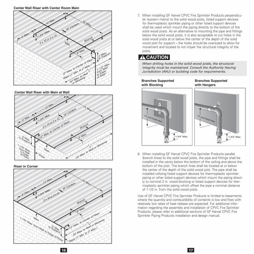
1. The ceiling shall be horizontal and constructed utilizing nominal 2 in. x 10 in. solid wood joists on 16 in. centers.
ORThe ceiling shall be horizontal and constructed utilizing nominal 2 in. x 12 in. solid wood joists on 16 in. centers. When installing GF Harvel BlazeMaster® CPVC pipe and fittings in conjunction with 2 in. x 12 in. solid wood joists, the maximum system working pressure under flowing conditions shall not exceed 100 psi and the maximum system working pressure under static (non-flowing) conditions shall not exceed 175 psi.
2. The distance from the floor to the bottom of the solid wood joists shall be between 7 ft. and 8 ft.
3. Listed residential pendent sprinklers with a maximum temperature rating of 155°F and a minimum K-factor of 3.0 are to be used for this type of installation. The maximum sprinkler spacing shall not exceed 12 feet. The system is to be designed based upon the Listed flows for the sprinkler selected except that the flow is not to be less than 11 gpm per sprinkler. The sprinklers are to be installed with their deflectors a maximum of 1-3/4 in. below the bottom of the solid wood joists in anticipation of future installation of a fin-ished ceiling. (reference NFPA 13D, Section 8.2.5, 2002 Edition)
4. All system mains shall be run perpendicular to the joists. All branch lines shall be run parallel to the joists. Schedule 80 fittings in the 1-1/2 in. and larger sizes shall be used.
5. All solvent cement joints shall be made with Spears FS-5 One-Step Solvent Cement.
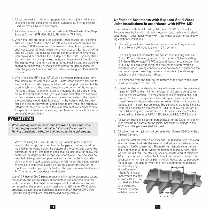
6. When the total protected area exceeds 1,000 square feet, blocking shall be utilized to divide the area into individual compartments not exceeding 1,000 square feet. The maximum length along the joist shall not exceed 32 feet. When the length exceeds 32 feet, block-ing shall be utilized. The blocking shall be constructed of minimum 1/2 in. plywood and shall be the full depth of the wood joists. It is acceptable for items such as piping, wires, ducts, etc. to penetrate the blocking. The gap between the item penetrating the blocking and the blocking should be mini-mized. For installa-tions where the gap exceeds 1/4 in., the gap shall be filled with insulation, caulking, or other suitable material.
Ceiling
Joist
Blocking
2 x 10 or 2 x 12
16"
16 17
Branches Supported with Blocking
Branches Supported with Hangers
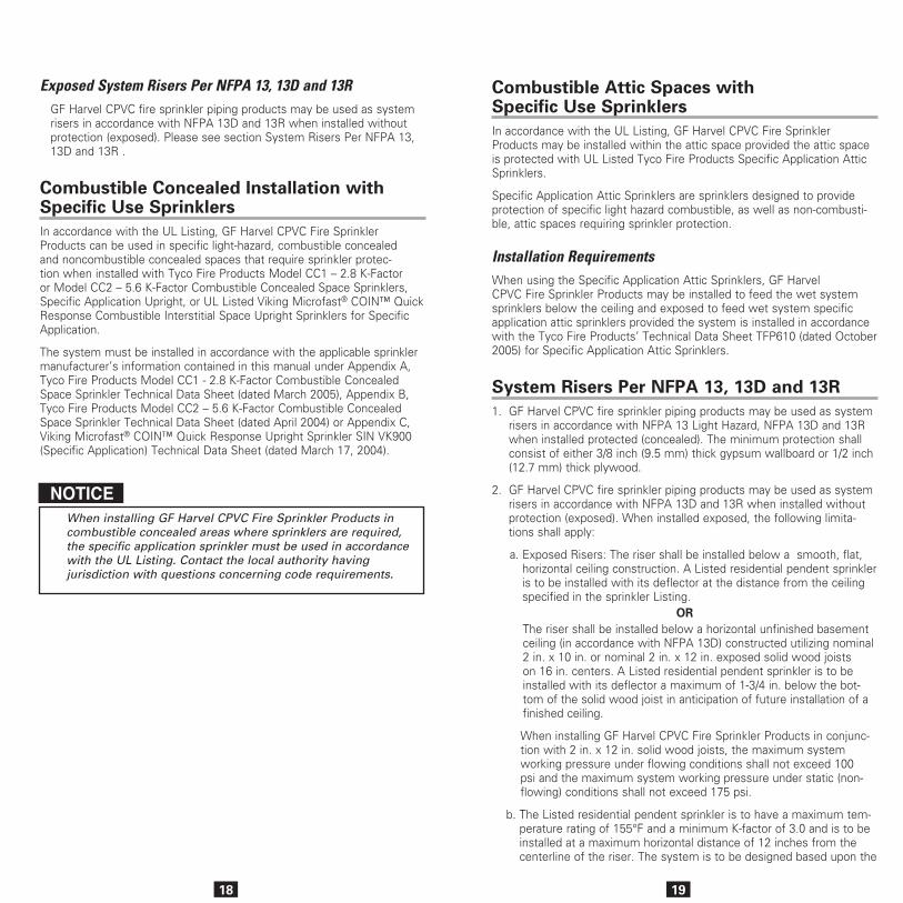
7. When installing GF Harvel CPVC Fire Sprinkler Products perpendicu-lar (system mains) to the solid wood joists, listed support devices for thermoplastic sprinkler piping or other listed support devices shall be used which mount the piping directly to the bottom of the solid wood joists. As an alternative to mounting the pipe and fittings below the solid wood joists, it is also acceptable to cut holes in the solid wood joists at or below the center of the depth of the solid wood joist for support – the holes should be oversized to allow for movement and located to not impair the structural integrity of the joists.
When drilling holes in the solid wood joists, the structural integrity must be maintained. Consult the Authority Having Jurisdiction (AHJ) or building code for requirements.
8. When installing GF Harvel CPVC Fire Sprinkler Products parallel (branch lines) to the solid wood joists, the pipe and fittings shall be installed in the cavity below the bottom of the ceiling and above the bottom of the joist. The branch lines shall be located at or below the center of the depth of the solid wood joist. The pipe shall be installed utilizing listed support devices for thermoplastic sprinkler piping or other listed support devices which mount the piping direct-ly to nominal 2 in. wood blocking or listed support devices for ther-moplastic sprinkler piping which offset the pipe a nominal distance of 1-1/2 in. from the solid wood joists.
Use of GF Harvel CPVC Fire Sprinkler Products is limited to basements where the quantity and combustibility of contents is low and fires with relatively low rates of heat release are expected. For additional infor-mation regarding the assembly and installation of CPVC Fire Sprinkler Products, please refer to additional sections of GF Harvel CPVC Fire Sprinkler Piping Products installation and design manual.
18 19
Combustible Attic Spaces with Specific Use Sprinklers In accordance with the UL Listing, GF Harvel CPVC Fire Sprinkler Products may be installed within the attic space provided the attic space is protected with UL Listed Tyco Fire Products Specific Application Attic Sprinklers.
Specific Application Attic Sprinklers are sprinklers designed to provide protection of specific light hazard combustible, as well as non-combusti-ble, attic spaces requiring sprinkler protection.
Installation RequirementsWhen using the Specific Application Attic Sprinklers, GF Harvel CPVC Fire Sprinkler Products may be installed to feed the wet system sprinklers below the ceiling and exposed to feed wet system specific application attic sprinklers provided the system is installed in accordance with the Tyco Fire Products’ Technical Data Sheet TFP610 (dated October 2005) for Specific Application Attic Sprinklers.
System Risers Per NFPA 13, 13D and 13R 1. GF Harvel CPVC fire sprinkler piping products may be used as system
risers in accordance with NFPA 13 Light Hazard, NFPA 13D and 13R when installed protected (concealed). The minimum protection shall consist of either 3/8 inch (9.5 mm) thick gypsum wallboard or 1/2 inch (12.7 mm) thick plywood.
2. GF Harvel CPVC fire sprinkler piping products may be used as system risers in accordance with NFPA 13D and 13R when installed without protection (exposed). When installed exposed, the following limita-tions shall apply:
a. Exposed Risers: The riser shall be installed below a smooth, flat, horizontal ceiling construction. A Listed residential pendent sprinkler is to be installed with its deflector at the distance from the ceiling specified in the sprinkler Listing.
ORThe riser shall be installed below a horizontal unfinished basement ceiling (in accordance with NFPA 13D) constructed utilizing nominal 2 in. x 10 in. or nominal 2 in. x 12 in. exposed solid wood joists on 16 in. centers. A Listed residential pendent sprinkler is to be installed with its deflector a maximum of 1-3/4 in. below the bot-tom of the solid wood joist in anticipation of future installation of a finished ceiling.
When installing GF Harvel CPVC Fire Sprinkler Products in conjunc-tion with 2 in. x 12 in. solid wood joists, the maximum system working pressure under flowing conditions shall not exceed 100 psi and the maximum system working pressure under static (non-flowing) conditions shall not exceed 175 psi.
b. The Listed residential pendent sprinkler is to have a maximum tem-perature rating of 155°F and a minimum K-factor of 3.0 and is to be installed at a maximum horizontal distance of 12 inches from the centerline of the riser. The system is to be designed based upon the
Exposed System Risers Per NFPA 13, 13D and 13R GF Harvel CPVC fire sprinkler piping products may be used as system risers in accordance with NFPA 13D and 13R when installed without protection (exposed). Please see section System Risers Per NFPA 13, 13D and 13R .
Combustible Concealed Installation with Specific Use SprinklersIn accordance with the UL Listing, GF Harvel CPVC Fire Sprinkler Products can be used in specific light-hazard, combustible concealed and noncombustible concealed spaces that require sprinkler protec-tion when installed with Tyco Fire Products Model CC1 – 2.8 K-Factor or Model CC2 – 5.6 K-Factor Combustible Concealed Space Sprinklers, Specific Application Upright, or UL Listed Viking Microfast® COIN™ Quick Response Combustible Interstitial Space Upright Sprinklers for Specific Application.
The system must be installed in accordance with the applicable sprinkler manufacturer’s information contained in this manual under Appendix A, Tyco Fire Products Model CC1 - 2.8 K-Factor Combustible Concealed Space Sprinkler Technical Data Sheet (dated March 2005), Appendix B, Tyco Fire Products Model CC2 – 5.6 K-Factor Combustible Concealed Space Sprinkler Technical Data Sheet (dated April 2004) or Appendix C, Viking Microfast® COIN™ Quick Response Upright Sprinkler SIN VK900 (Specific Application) Technical Data Sheet (dated March 17, 2004).
NOTICEWhen installing GF Harvel CPVC Fire Sprinkler Products in combustible concealed areas where sprinklers are required, the specific application sprinkler must be used in accordance with the UL Listing. Contact the local authority having jurisdiction with questions concerning code requirements.
20
listed flows for the sprinkler selected except that the flow is not to be less than 11 gpm per sprinkler.
c. The riser shall be supported vertically within 2 feet of the ceiling or bottom of the joist.
d. The minimum riser diameter shall be 1 in. and the maximum riser diameter shall be 2 in.
e. The maximum distance between the wall(s) and the outside surface of the riser pipe shall be 1-1/2 in.
f. All solvent cement joints shall be made with Spears FS-5 One-Step Solvent Cement in strict accordance with GF Harvel’s assembly instructions for the application of One-Step cement.
g. These instructions are applicable only to UL Listed BlazeMaster® CPVC pipe and fittings, and require the use of Schedule 80 fittings for riser sizes 1-1/2 in. and larger.
3. The system shall be installed per the requirements of NFPA 13, Section 9.2.5 (2002 Edition), Support of Risers.
4. GF Harvel CPVC Fire Sprinkler Products shall be installed per GF Harvel CPVC Fire Sprinkler Piping Products installation and design manual.
5. Risers shall be supported by pipe clamps or by hangers located on the horizontal connection close to the riser. Only Listed hangers and clamps shall be used.
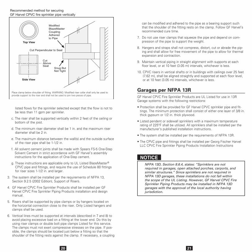
6. Vertical lines must be supported at intervals (described in 7 and 8) to avoid placing excessive load on a fitting at the lower end. Do this by using riser clamps or double bolt pipe clamps Listed for this service. The clamps must not exert compressive stresses on the pipe. If pos-sible, the clamps should be located just below a fitting so that the shoulder of the fitting rests against the clamp. If necessary, a coupling
Recommended method for securingGF Harvel CPVC fire sprinkler pipe vertically
Place clamp below shoulder of fitting. WARNING: Modified riser collar shall only be used to provide support to the riser and shall not be used to join two pieces of pipe.
21
can be modified and adhered to the pipe as a bearing support such that the shoulder of the fitting rests on the clamp. Follow GF Harvel’s recommended cure time.
7. Do not use riser clamps that squeeze the pipe and depend on com-pression of the pipe to support the weight.
8. Hangers and straps shall not compress, distort, cut or abrade the pip-ing and shall allow for free movement of the pipe to allow for thermal expansion and contraction.
9. Maintain vertical piping in straight alignment with supports at each floor level, or at 10 feet (3.05 m) intervals, whichever is less.
10. CPVC risers in vertical shafts or in buildings with ceilings over 25 feet (7.62 m), shall be aligned straightly and supported at each floor level, or at 10 feet (3.05 m) intervals, whichever is less.
Garages per NFPA 13RGF Harvel CPVC Fire Sprinkler Products are UL Listed for use in 13R Garage systems with the following restrictions:
• Protection shall be provided for GF Harvel CPVC sprinkler pipe and fit-tings. The minimum protection shall consist of either one layer of 3/8 in. thick gypsum or 1/2 in. thick plywood.
• Listed pendent or sidewall sprinklers with a maximum temperature rating of 225°F shall be utilized. All sprinklers shall be installed per the manufacturer’s published installation instructions.
• The system shall be installed per the requirements of NFPA 13R.
• The CPVC pipe and fittings shall be installed per Georg Fischer Harvel LLC CPVC Fire Sprinkler Piping Products Installation Instructions
NOTICENFPA 13D, Section 8.6.4, states: “Sprinklers are not required in garages, open attached porches, carports, and similar structures.” Since sprinklers are not required in NFPA 13D garages, these installations do not fall within the scope of the UL Listing. However, GF Harvel CPVC Fire Sprinkler Piping Products may be installed in NFPA 13D garages with the approval of the local authority having jurisdiction.
22
Underground Fire ServiceGF Harvel CPVC Fire Sprinkler Products are UL Listed and C-UL Listed for use in underground water service when installation is in accordance with:
• ASTM D2774, Standard Recommended Practice for Underground Installation of Thermoplastic Pressure Piping,
• ASTM F645, Standard Guide For Selection Design and Installation of Thermoplastic Water Pressure Piping Systems,
• Georg Fischer Harvel LLC’s procedures
• Installation of private fire service mains and their appurtenances, NFPA 24.
The general installation procedure detailed here applies to CPVC Fire Sprinkler pressure pipe that has solvent cement joints in size range 3/4 – 3 inches.
InspectionBefore installation, CPVC Products should be thoroughly inspected for cuts, scratches, gouges or split ends which may have occurred to the products during shipping and handling.
TrenchingThe trench should be of adequate width to allow convenient installation, while at the same time being as narrow as possible. Minimum trench widths may be utilized by joining pipe outside of the trench and lowering it into the trench after adequate joint strength has been achieved. (NOTE: Refer to manufacturer’s instructions for recommended set and cure time for solvent cement joints.) Trench widths will have to be wider where pipe is joined in the trench or where thermal expansion and contraction is a factor. See “Snaking of Pipe” on the next page.
• Water filled pipe should be buried at least 12 inches below the maxi-mum expected frost line.
• It is recommended that thermoplastic piping be run within a metal or concrete casing when it is installed beneath surfaces that are sub-ject to heavyweight or constant traffic such as roadways and railroad tracks.
The trench bottom should be continuous, relatively smooth and free of rocks. Where ledge rock, hardpan or boulders are encountered, it is nec-essary to pad the trench bottom using a minimum of 4 inches of tamped earth or sand beneath the pipe as a cushion and for protection of the pipe from damage.
Sufficient cover must be maintained to keep external stress levels below acceptable design stress. Reliability and safety of service is of major
Pipe Size Trench Width Light TrafficGround Cover
Minimum
Heavy TrafficGround Cover
Minimum
3" and under 8" 12"-18" 30"- 36"
23
importance in determining minimum cover. Local, state and national codes may also govern.
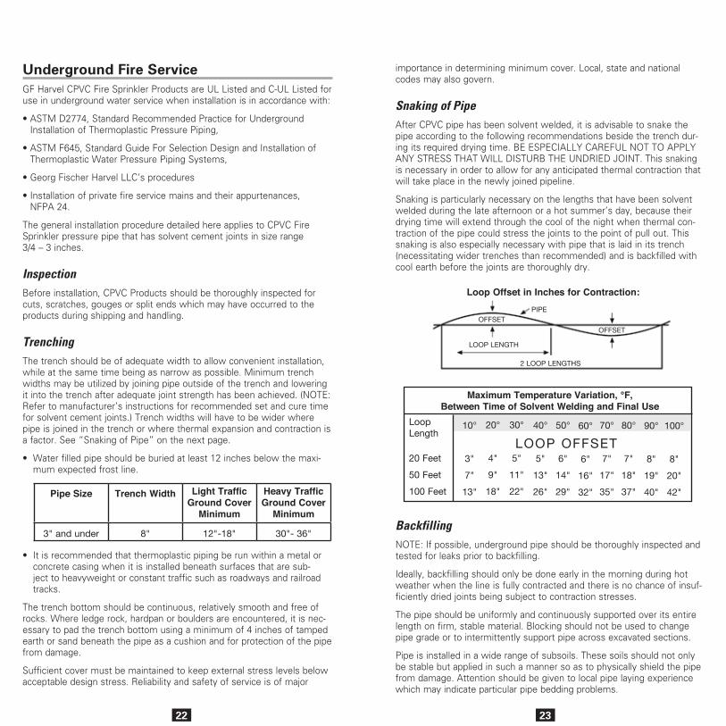
Snaking of PipeAfter CPVC pipe has been solvent welded, it is advisable to snake the pipe according to the following recommendations beside the trench dur-ing its required drying time. BE ESPECIALLY CAREFUL NOT TO APPLY ANY STRESS THAT WILL DISTURB THE UNDRIED JOINT. This snaking is necessary in order to allow for any anticipated thermal contraction that will take place in the newly joined pipeline.
Snaking is particularly necessary on the lengths that have been solvent welded during the late afternoon or a hot summer’s day, because their drying time will extend through the cool of the night when thermal con-traction of the pipe could stress the joints to the point of pull out. This snaking is also especially necessary with pipe that is laid in its trench (necessitating wider trenches than recommended) and is backfilled with cool earth before the joints are thoroughly dry.
BackfillingNOTE: If possible, underground pipe should be thoroughly inspected and tested for leaks prior to backfilling.
Ideally, backfilling should only be done early in the morning during hot weather when the line is fully contracted and there is no chance of insuf-ficiently dried joints being subject to contraction stresses.
The pipe should be uniformly and continuously supported over its entire length on firm, stable material. Blocking should not be used to change pipe grade or to intermittently support pipe across excavated sections.
Pipe is installed in a wide range of subsoils. These soils should not only be stable but applied in such a manner so as to physically shield the pipe from damage. Attention should be given to local pipe laying experience which may indicate particular pipe bedding problems.
Loop Offset in Inches for Contraction:
Maximum Temperature Variation, °F,Between Time of Solvent Welding and Final Use
LOOP OFFSET
10°
3"
7"
13"
20°
4"
9"
18"
30°
5"
11"
22"
40°
5"
13"
26"
50°
6"
14"
29"
60°
6"
16"
32"
70°
7"
17"
35"
80°
7"
18"
37"
90°
8"
19"
40"
100°
8"
20"
42"
LoopLength
20 Feet
50 Feet
100 Feet
PIPEOFFSET
OFFSET
LOOP LENGTH
2 LOOP LENGTHS
24
Backfill materials free of rocks with a particle size of 1/2 inch or less should be used to surround the pipe with 6 inches or 8 inches of cover. It should be placed in layers. Each soil layer should be sufficiently com-pacted to uniformly develop lateral passive soil forces during the backfill operation. It may be advisable to have the pipe under pressure, 15 to 25 psi during the backfilling.
Vibratory methods are preferred when compacting sand or gravels. Best results are obtained when the soils are in a nearly saturated condition. Where water flooding is used, the initial backfill should be sufficient to insure complete coverage of the pipe. Additional material should not be added until the water flooded backfill is firm enough to walk on. Care should be taken to avoid floating the pipe.
Sand and gravel containing a significant proportion of fine-grained mate-rial, such as silt and clay, should be compacted by hand or, preferably by mechanical tamper.
The remainder of the backfill should be placed and spread in uniform lay-ers in such a manner to fill the trench completely so that there will be no unfilled spaces under or about rocks or lumps of earth in the backfill. Large or sharp rocks, frozen clods and other debris greater than 3 inches in diameter should be removed. Rolling equipment or heavy tampers should only be used to consolidate the final backfill.
MaintenanceShall be in accordance with the Standard for Inspection, Testing and Maintenance or Water Based Extinguishing Systems as defined by NFPA 25.
Ordinary Hazard InstallationsGF Harvel CPVC Fire Sprinkler Piping Products are not Listed for use in Ordinary Hazard occupancies per NFPA 13. However, per the excep-tion noted in Section 6.3.6.2 of the 2002 edition of NFPA 13, GF Harvel CPVC Fire Sprinkler Piping Products can be used to protect ordinary haz-ard rooms of otherwise light hazard occupancies where the room does not exceed 400 ft2 when installed in accordance with other installation requirements specified within this manual.
25
GF Harvel CPVC Fire Sprinkler Products are C-UL Listed in accordance with Canadian requirements for use in:
• Light Hazard occupancies defined in the Standard for Installation of Sprinkler Systems, NFPA 13
• Residential occupancies as defined in the Standard for Installation of Sprinkler Systems in Residential Occupancies up to Four Stories in Height, NFPA 13R
• Residential occupancies as defined in the Standard for Installation of Sprinkler Systems in One and Two Family Dwelling and Mobile Homes, NFPA 13D.
Protected InstallationsWhen used with standard response sprinklers, protection shall be provided for GF Harvel CPVC piping products by ceilings, walls or soffits consisting of the following minimum protection: lath and plaster, 9 mm thick gypsum wallboard, 13 mm thick plywood or a suspended membrane ceiling with lay-in panels or tiles, classified with respect to surface burning characteristics having mass of not less than 1.7 kg/sq m and installed in steel suspension grids. The effec-tiveness of this protection can be impaired if penetrated by openings such as ventilation grills, exhaust fans connected to metal ducts serving washrooms excepted. Where such penetration is present, individual openings exceeding 0.03 sq m but not exceeding 0.71 sq m in an area must be located so that the distance from the edge of the opening to the nearest sprinkler does not exceed 300 mm. This piping shall not be used where such openings exceed 0.71 sq m in area. The effect of the presence of non-rated recessed lighting fixtures, public address speakers and other interruptions of the protective membrane has not been investigated.
Exposed InstallationsAs an alternative to the protection requirements, GF Harvel CPVC Fire Sprinkler Products may be installed without protection (exposed) when subject to the following additional limitations:
• Exposed piping is to be installed below a smooth, flat, horizontal, fixed ceiling construction.
• Listed Quick-Response pendent sprinklers having deflectors installed within 8 inches from ceiling or Listed Residential pendent located in accordance with their Listing and a maximum distance between sprinklers not to exceed 15 feet.
• Listed Quick-Response horizontal sidewall sprinklers having deflectors installed within 6 inches from the ceiling and within 4 inches of the sidewall or Listed Residential horizontal sidewall sprinklers located in accordance with their Listing and a maximum distance between sprinklers not to exceed 14 feet.
During remodeling or repair, appropriate precautions shall be implemented to properly shield the piping from the protected occupancy.
GF Harvel CPVC Fire Sprinkler Piping Products are to be installed in accordance with the requirements specified in NFPA 13, NFPA 13R or NFPA 13D and the National Building Code of Canada. GF Harvel CPVC Fire Sprinkler Piping Products must be installed in accordance with the other special installation and design criteria relative to handling, assembly, pipe hanger spacing, piping and sprinkler restraint, sprinkler temperature rating, piping location, testing procedures, friction loss characteristics and other applicable requirements specified in the installation instructions for product. The use of GF Harvel CPVC Fire Sprinkler Products in ceiling spaces above non-sprinklered areas has not been investigated.
GF Harvel CPVC Fire Sprinkler Piping Products are Listed for use in wet pipe systems only, and are not Listed for outdoor use.
C-UL Listing Requirements

26
Dry Pipe ApplicationIn accordance with the UL® Listing, GF Harvel BlazeMaster® CPVC Fire Sprinkler Products may be used in Low Pressure Dry Pipe and Pre-action System applications in Light Hazard and Residential occupancies in accordance with NFPA 13, 13D and 13R when subject to the follow-ing additional limitations:
A CPVC Low Pressure Dry Pipe or Pre-action System is a piping sys-tem intended for use where piping could be subjected to freezing tem-peratures and water filled pipe cannot be utilized. The minimum rated temperature is -20°F (-29°C). Low Pressure Dry Pipe systems contain compressed air or nitrogen (gas) having an internal gage pressure of not more than 15 psig (105 kPa). These specially designed systems require separate control valve mechanisms for this application (sup-plied by others) that activate to release water into the dry piping sec-tion and to the sprinkler heads. The water-filled portion of the system control device must be in an area protected from freezing. It is the installer’s responsibility to be sure the system is installed in accor-dance with the limitations of this manual and specifications of a Dry Pipe or Pre-action Fire Sprinkler System design Engineer for proper control devices, pipe sizing, and other important design and mainte-nance criteria applicable to each project.
GF Harvel BlazeMaster CPVC Fire Sprinkler Products are UL® Listed for use in Dry Pipe or Pre-action type systems when installed with UL® Listed Spears® FlameGuard®, or BlazeMaster® brands of CPVC Fire Sprinkler Pipe and fittings that are also Listed for this application.
CPVC installation in a Dry Pipe or Preaction sprinkler system must be concealed (protected) by either:
1. A 3/8 in. thick or thicker gypsum wallboard,
2. A suspended membrane ceiling with lay-in panels or tiles having a weight of not less than 0.35 lb/ft2 when installed with metallic sup-port grids, or
3. 1/2 in. plywood soffits.
CPVC pipe and fittings used in a Dry Pipe or Pre-action System are not for use in combustible concealed spaces where sprinklers are required by NFPA 13, 3D and 13R.
Pipe and fittings are for indoor use only, down to a minimum tempera-ture of -20°F (-29°C).
CPVC pipe in Low Pressure Dry or Pre-action Systems must be installed with proper pitch to allow system drainage for removal of water. NFPA 13 requires a minimum pitch of 1/2 in. per 10 feet (4 mm/m) for main lines and branch lines in areas subject to freezing.
Low Pressure Dry Systems have a maximum installed air pressure of 15 psi (1 BAR). Air (or Nitrogen) supply for charging the system must be filtered, clean, oil-free, and must be pressure regulated to assure that the 15 psi (1 BAR) pressurization is not exceeded.
OIL IN THE AIR (OR NITROGEN) SUPPLY CAN CAUSE ENVIRONMENTAL STRESS CRACKING IN CPVC MATERIALS.
OVER PRESSURIZATION CAN RESULT IN SYSTEM DAMAGE OR SERIOUS INJURY.
27
BlazeMaster® CPVC pipe and fittings are FM Approved for use in:
• Miscellaneous non-manufacturing occupancies as described in FM Loss Prevention Data Sheet 3-26, “Fire Protection Water Demand for Nonstorage Sprinklered Properties”, Table 2, Section L.
• Residential occupancies as described in FM Loss Prevention Data Sheet 2-8N, “Installation of Sprinkler Systems”. BlazeMaster Fire Sprinkler Systems shall be employed in wet pipe systems only. (A wet pipe system contains water or water and glycerin (anti-freeze solu-tion) and is connected to a water supply so that the water or water and glycerin (anti-freeze solution) will discharge immediately when the sprinkler is opened).
Concealed Installations (FM)In accordance with the FM Approval, protection shall be provided for BlazeMaster CPVC pipe and fittings as follows:
• The minimum protection shall consist of either a permanently installed non-combustible barrier from any area protected by the system.
NOTICEA permanently installed barrier is one that cannot be removed without substantial cosmetic damage. Drop in ceiling tiles, as used in suspended ceilings are specifi-cally considered not be permanently installed for the pur-poses of this definition. Non-combustible is defined as having a minimum finish fire rating of 15 minutes when tested per ASTM E119.
• As an alternative to the protection of a permanently installed noncom-bustible barrier, FM has approved the use of BlazeMaster CPVC with the Soffi-Steel® covering system manufactured by Grice Engineering.
• FM Approved quick response, standard or extended coverage, or FM Approved residential sprinklers installed in accordance with their approval limitations may be used.
• Solvent cement joints shall be made One-Step Solvent Cement.
Exposed Installations – Smooth, Flat, Horizontal Ceilings (FM)In accordance with the FM Approval, BlazeMaster pipe and fittings may be installed without protection (exposed), subject to the following addi-tional limitations:
NOTICEWhere piping is installed above drop-in ceiling tiles, the piping shall be considered exposed.
Factory Mutual (FM)
(cont.)
28
Standard Coverage Sprinklers• Pendent sprinklers shall be FM Approved, quick response sprinklers
having deflectors installed within 8 inches (203.2 mm) of the ceiling. The maximum distance between sprinklers shall not exceed 15 feet (4.6 m). The maximum ceiling height shall not exceed 10 feet (3.0 m).
• Upright sprinklers shall be FM Approved, quick response sprinklers having deflectors installed within 4 inches (101.6 mm) of the ceiling. The maximum distance between sprinklers shall not exceed 15 feet (4.6 m). The maximum distance from the ceiling to the centerline of the main run of pipe shall not exceed 7 feet 1/2 inch (2.3 m). The distance from the centerline of the sprinkler to the closest hanger shall be 3 inches (76.2 mm). The maximum ceiling height shall not exceed 10 feet (3.0 m).
• Horizontal Sidewall Sprinklers shall be FM Approved, quick response sprinklers having deflectors installed within 12 inches (304.8 mm) of the ceiling and within 6 inches (152.4 mm) of the side wall. The maxi-mum distance between sprinklers shall not exceed 14 feet (4.3 m). The maximum ceiling height shall not exceed 10 feet (3.0 m).
• Solvent cement joints shall be made One-Step Solvent Cement.
Extended Coverage Sprinklers• Pendent sprinklers shall be FM Approved, quick response sprinklers
having deflectors installed within 8 inches (203.2 mm) of the ceiling. The maximum distance between sprinklers shall not exceed 20 feet (6.1 m). When the sprinklers are not on square spacings, the flow for a sprinkler should be based on the density applied over the square area calculated for the largest dimension of the sprinkler spacing. The maximum ceiling height shall not exceed 10 feet (3.0 m).
• Horizontal Sidewall Sprinklers shall be FM Approved, quick response sprinklers having deflectors installed within 12 inches (304.8 mm) of the ceiling and within 6 inches (152.4 mm) of the side wall.
• The maximum lateral distance between sprinklers shall not exceed 16 feet (4.9 m). The maximum ceiling height shall not exceed 10 feet (3.0 m).
• The minimum flow or pressure established for Extended Coverage Systems shall be per FM Loss Prevention Data Sheet 2-8N and 3-26.
• Solvent cement joints shall be made One-Step Solvent Cement.
Factory Mutual (FM) (cont.)
29
Residential Sprinklers• Pendent sprinklers shall be FM Approved, residential sprinklers
having deflectors installed within 8 inches (203.2 mm) of the ceiling. The maximum distance between sprinklers shall not exceed 20 feet (6.1 m). The minimum required discharge from each sprinkler is to be the greater of either the approved flow rate applied over the square area calculated for the largest dimension of the sprinkler spacing or a minimum discharge of 0.1 gpm/ft2 (4.1 mm/min) over the actual area (S x L) covered by the sprinkler. The maximum ceiling height shall not exceed 10 feet (3.0 m).
Listings and Approvals• Horizontal Sidewall Sprinklers shall be FM Approved, quick response
sprinklers having deflectors installed within 12 inches (304.8 mm) of the ceiling and within 6 inches (152.4 mm) of the side wall. The maxi-mum lateral distance between sprinklers shall not exceed 16 feet (4.9 m). The minimum required discharge from each sprinkler is to be the greater of either the approved flow rate applied over the area calculated for the largest dimension of the sprinkler spacing or a mini-mum discharge of 0.1 gpm/ft2 (4.1 mm/min) over the actual area (S x L) covered by the sprinkler. The maximum ceiling height shall not exceed 10 feet (3.0 m).
• The minimum flow or pressure established for Residential Sprinkler Systems shall be per FM Loss Prevention Data Sheet 2-8N and 3-26.
• Solvent cement joints shall be made One-Step Solvent Cement.
System Risers (FM)In accordance with the FM Approval, BlazeMaster pipe and fittings may be installed without protection (exposed) as a vertical riser when subject to the following additional limitations:
• An automatic sprinkler (of the same type as in the area being protected) shall be located adjacent to and no further than 1 foot (0.3 m) from the riser.
• The automatic sprinkler protecting the riser shall not be considered when determining protection criteria for the floor area. The design flow for the sprinkler protecting the riser must be the same as for the other sprinklers, and must be added to the hydraulic calculation.
• Solvent cement joints shall be made One-Step Solvent Cement.
30
WARRANTY
Handling and StorageGF Harvel CPVC Fire Sprinkler Products are tough and corrosion resistant, but do not have the mechanical strength of steel. Reasonable care should be exercised in handling GF Harvel CPVC.
Fire Sprinkler Products. They must not be dropped or have objects dropped on them. If improper handling results in scratches, splits or gouges, the damaged section shall be cut out and discarded.
GF Harvel CPVC Fire Sprinkler pipe must be covered with a non-transpar-ent material when stored out of doors. Brief exposure to direct sunlight on the job site may result in color fade but will not affect physical proper-ties. CPVC Fire Sprinkler fittings can be stored in their original containers to keep them free from dirt and reduce the possibility of damage.
Transition to Other MaterialsSpecially designed female threaded adapters, grooved coupling adapters, and flanges are listed for connecting a GF Harvel CPVC Fire Sprinkler system to other materials, valves, and accessories. A special reinforced female threaded adapter is available for connection to the sprinkler head.
Threaded Connections
Some thread paste sealants contain solvents or other chemical additives that can cause damage to CPVC. Only compatible thread sealants and tapes should be used.
Georg Fischer Harvel LLC recommends the use of a quality PTFE (polytetrafluoroethylene) thread tape, having a thickness of .0025 in. or greater and meeting or exceeding military specification MIL-T-27730A for all threaded connections. The use of other thread sealants may result in damage to the GF Harvel CPVC Fire Sprinkler Products.
Starting with the first full thread and continuing over the entire thread length, making sure that all the threads are covered, wrap thread tape in the direction of the threads. Generally 2-3 wraps is sufficient.
Care must be taken to avoid overtorquing – generally 1 to 2 turns beyond finger tight is all that is required to make up a threaded connection. Factory testing has indicated 10-25 ft. lbs. of torque is adequate to obtain a leak free seal. Georg Fischer Harvel LLC recommends the use of a strap wrench when making up threaded connections.
Sprinkler head adapters are manufactured with a brass thread insert to provide a high strength, heavy duty fitting for threaded connections with male metal threads.
Sprinkler heads shall be installed only after all the fire sprinkler pipe fittings, including the sprinkler head adapters, are solvent welded to the piping and have been allowed to cure as recommended in the cure chart. Plastic threaded plugs are available for use in pressure testing.
Installation
31
Exercise care when installing sprinklers. Allow sprinkler head fittings and previously joined fittings to cure for a minimum of 30 minutes prior to installing the sprinkler. When installing sprinklers, be sure to anchor or hold the pipe drop securely to avoid rotating the pipe in previously cemented connections.
It is an unacceptable practice to assemble sprinklers into the head adapter fittings and then solvent cement them to the drop.
Failure to allow sprinkler fitting joints to cure before installing sprinklers may result in cement in the sprinkler waterway. Too much solvent cement can cause clogged waterways.
• Visually inspect sprinkler fittings to ensure that the water-way and threads are clear of any excess cement.
• Install sprinkler heads only after all the CPVC pipe and fit-tings, including the sprinkler adapters, are solvent weld-ed and allowed to cure for a minimum of 30 minutes.
• Do not install sprinklers in the fittings prior to the fittings being cemented in place.
32
Flanged ConnectionsFLANGE MAKE-UP: Once a flange is joined to pipe, the method for join-ing two flanges is as follows:
A. Piping runs joined to the flanges must be installed in a straight line position to the flange to avoid stress at the flange due to misalign-ment. Piping must also be secured and supported to prevent lateral movement which can create stress and damage the flange.
B. With gasket in place, align the bolt holes of the mating flanges by rotating the ring into position. (Consideration should be given to align-ment of One-Piece Flange prior to joining with pipe.)
C. Insert all bolts, washers (two standard flat washers per bolt), and nuts.
D. Make sure the faces of the mating surfaces are flush against gasket prior to bolting down the flanges.
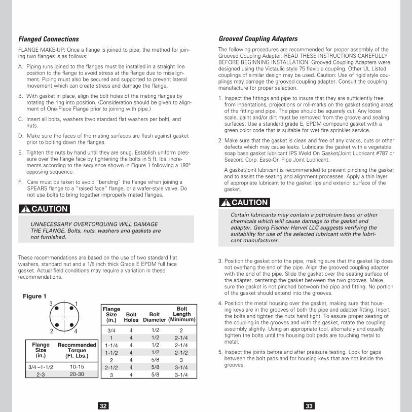
E. Tighten the nuts by hand until they are snug. Establish uniform pres-sure over the flange face by tightening the bolts in 5 ft. lbs. incre-ments according to the sequence shown in Figure 1 following a 180° opposing sequence.
F. Care must be taken to avoid “bending” the flange when joining a SPEARS flange to a “raised face” flange, or a wafer-style valve. Do not use bolts to bring together improperly mated flanges.
UNNECESSARY OVERTORQUING WILL DAMAGE THE FLANGE. Bolts, nuts, washers and gaskets are not furnished.
These recommendations are based on the use of two standard flat washers, standard nut and a 1/8 inch thick Grade E EPDM full face gasket. Actual field conditions may require a variation in these recommendations.
RecommendedTorque
(Ft. Lbs.)
FlangeSize(in.)
3/4 –1-1/22-3
10-1520-30
3/41
1-1/41-1/2
22-1/2
3
4444444
1/21/21/21/25/85/85/8
22-1/42-1/42-1/2
33-1/43-1/4
FlangeSize(in.)
BoltHoles
BoltDiameter
BoltLength
(Minimum)
3
42
1Figure 1
33
Grooved Coupling AdaptersThe following procedures are recommended for proper assembly of the Grooved Coupling Adapter. READ THESE INSTRUCTIONS CAREFULLY BEFORE BEGINNING INSTALLATION. Grooved Coupling Adapters were designed using the Victaulic style 75 flexible coupling. Other UL Listed couplings of similar design may be used. Caution: Use of rigid style cou-plings may damage the grooved coupling adapter. Consult the coupling manufacture for proper selection.
1. Inspect the fittings and pipe to insure that they are sufficiently free from indentations, projections or roll-marks on the gasket seating areas of the fitting and pipe. The pipe should be squarely cut. Any loose scale, paint and/or dirt must be removed from the groove and sealing surfaces. Use a standard grade E, EPDM compound gasket with a green color code that is suitable for wet fire sprinkler service.
2. Make sure that the gasket is clean and free of any cracks, cuts or other defects which may cause leaks. Lubricate the gasket with a vegetable soap base gasket lubricant IPS Weld On Gasket/Joint Lubricant #787 or Seacord Corp. Ease-On Pipe Joint Lubricant.
A gasket/joint lubricant is recommended to prevent pinching the gasket and to assist the seating and alignment processes. Apply a thin layer of appropriate lubricant to the gasket lips and exterior surface of the gasket.
Certain lubricants may contain a petroleum base or other chemicals which will cause damage to the gasket and adapter. Georg Fischer Harvel LLC suggests verifying the suitability for use of the selected lubricant with the lubri-cant manufacturer.
3. Position the gasket onto the pipe, making sure that the gasket lip does not overhang the end of the pipe. Align the grooved coupling adapter with the end of the pipe. Slide the gasket over the seating surface of the adapter, centering the gasket between the two grooves. Make sure the gasket is not pinched between the pipe and fitting. No portion of the gasket should extend into the grooves.
4. Position the metal housing over the gasket, making sure that hous-ing keys are in the grooves of both the pipe and adapter fitting. Insert the bolts and tighten the nuts hand tight. To assure proper seating of the coupling in the grooves and with the gasket, rotate the coupling assembly slightly. Using an appropriate tool, alternately and equally tighten the bolts until the housing bolt pads are touching metal to metal.
5. Inspect the joints before and after pressure testing. Look for gaps between the bolt pads and for housing keys that are not inside the grooves.
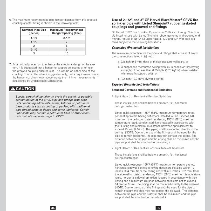
6. The maximum recommended pipe hanger distance from this grooved coupling adapter fitting is shown in the following table.
7. As an added precaution to enhance the structural design of the sys-tem, it is suggested that a hanger or support be located at or near the grooved coupling adapter joint. This can be on either side of the coupling. This is offered as a suggestion only, not a requirement, since the hanger spacing shown above meets the minimum requirements established by Underwriters Laboratories.
Special care shall be taken to avoid the use of, or possible contamination of the CPVC pipe and fittings with prod-ucts containing edible oils, esters, ketones or petroleum base products such as cutting or packing oils, traditional pipe thread paste or dopes and some lubricants. Certain Lubricants may contain a petroleum base or other chemi-cals that will cause damage to CPVC.
35
Use of 2-1/2" and 3" GF Harvel BlazeMaster® CPVC fire sprinkler pipe with Listed Shurjoint® rubber gasketed couplings and grooved end fittings
GF Harvel CPVC Fire Sprinkler Pipe in sizes 2-1/2 inch through 3 inch, is UL listed for use with Listed Shurjoint rubber-gasketed and grooved end fittings, for use in NFPA 13 Light Hazard, 13D and 13R wet pipe sys-tems subject to the following limitations:
Concealed (Protected) Installations
The minimum protection for the pipe and fittings shall consist of any of the constructions listed in (a) - (c).
a. 3/8 inch (9.5 mm) thick or thicker gypsum wallboard, or
b. A suspended membrane ceiling with lay-in panels or tiles having a weight of not less than 0.35 lb/ft2 (1.76 kg/m2) when installed with metallic support grids; or
c. 1/2 inch (12.7 mm) plywood soffits.
Exposed (Unprotected) Installations
Standard Coverage and Residential Sprinklers
1. Light Hazard or Residential Pendent Sprinklers These installations shall be below a smooth, flat, horizontal ceiling construction. Listed quick response, 155°F (68°C) maximum temperature rated, pendent sprinklers having deflectors installed within 8 inches (203 mm) from the ceiling or Listed residential, 155°F (68°C) maximum temperature rated, pendent sprinklers located in accordance with their Listing and a maximum distance between sprinklers not to exceed 15 feet (4.57 m). The piping shall be mounted directly to the ceiling. (NOTE: Due to the size of the fittings and the need for the pipe to remain horizontal, the pipe may not contact the ceiling. The distance between the pipe and the ceiling shall be minimized and the pipe support shall be attached to the ceiling.)
2. Light Hazard or Residential Horizontal Sidewall Sprinklers These installations shall be below a smooth, flat, horizontal ceiling construction. Listed quick response, 155°F (68°C) maximum temperature rated, horizontal sidewall sprinklers having deflectors installed within 12 inches (304 mm) from the ceiling and within 6 inches (152 mm) from the sidewall or Listed residential, 155°F (68°C) maximum temperature rated, horizontal sidewall sprinklers located in accordance with their Listing and a maximum distance between sprinklers not to exceed 14 feet (4.27 m). The piping shall be mounted directly to the sidewall. (NOTE: Due to the size of the fittings and the need for the pipe to remain straight the pipe may not contact the sidewall. The distance between the pipe and the sidewall shall be minimized and the pipe support shall be attached to the sidewall.)
34
Maximum RecommendedHanger Spacing (Feet)
Nominal Pipe Size(Inches)
1-1/41-1/2
22-1/2
3
6-1/278910
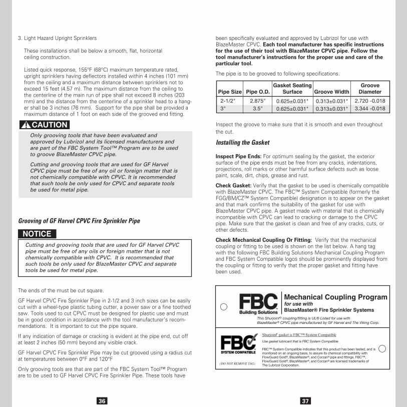
3736
3. Light Hazard Upright Sprinklers These installations shall be below a smooth, flat, horizontal ceiling construction. Listed quick response, 155°F (68°C) maximum temperature rated, upright sprinklers having deflectors installed within 4 inches (101 mm) from the ceiling and a maximum distance between sprinklers not to exceed 15 feet (4.57 m). The maximum distance from the ceiling to the centerline of the main run of pipe shall not exceed 8 inches (203 mm) and the distance from the centerline of a sprinkler head to a hang-er shall be 3 inches (76 mm). Support for the pipe shall be provided a maximum distance of 1 foot on each side of the grooved end fitting.
Only grooving tools that have been evaluated and approved by Lubrizol and its licensed manufacturers and are part of the FBC System Tool™ Program are to be used to groove BlazeMaster CPVC pipe.
Cutting and grooving tools that are used for GF Harvel CPVC pipe must be free of any oil or foreign matter that is not chemically compatible with CPVC. It is recommended that such tools be only used for CPVC and separate tools be used for metal pipe.
Grooving of GF Harvel CPVC Fire Sprinkler Pipe
NOTICECutting and grooving tools that are used for GF Harvel CPVC pipe must be free of any oils or foreign matter that is not chemically compatible with CPVC. It is recommended that such tools be only used for BlazeMaster CPVC and separate tools be used for metal pipe.
The ends of the must be cut square.
GF Harvel CPVC Fire Sprinkler Pipe in 2-1/2 and 3 inch sizes can be easily cut with a wheel-type plastic tubing cutter, a power saw or a fine toothed saw. Tools used to cut CPVC must be designed for plastic use and must be in good condition in accordance with the tool manufacturer’s recom-mendations. It is important to cut the pipe square.
If any indication of damage or cracking is evident at the pipe end, cut off at least 2 inches (50 mm) beyond any visible crack.
GF Harvel CPVC Fire Sprinkler Pipe may be cut grooved using a radius cut at temperatures between 0°F and 120°F
Only grooving tools are that are part of the FBC System Tool™ Program are to be used to GF Harvel CPVC Fire Sprinkler Pipe. These tools have
been specifically evaluated and approved by Lubrizol for use with BlazeMaster CPVC. Each tool manufacturer has specific instructions for the use of their tool with BlazeMaster CPVC pipe. Follow the tool manufacturer’s instructions for the proper use and care of the particular tool.
The pipe is to be grooved to following specifications.
Inspect the groove to make sure that it is smooth and even throughout the cut.
Installing the Gasket
Inspect Pipe Ends: For optimum sealing by the gasket, the exterior surface of the pipe ends must be free from any cracks, indentations, projections, roll marks or other harmful surface defects such as loose paint, scale, dirt, chips, grease and rust.
Check Gasket: Verify that the gasket to be used is chemically compatible with BlazeMaster CPVC. The FBC™ System Compatible (formerly the FGG/BM/CZ™ System Compatible) designation is to appear on the gasket and that mark confirms the suitability of the gasket for use with BlazeMaster CPVC pipe. A gasket made with material that is chemically incompatible with CPVC can lead to cracking or damage to the CPVC pipe. Make sure that the gasket is clean and free of any cracks, cuts, or other defects.
Check Mechanical Coupling Or Fitting: Verify that the mechanical coupling or fitting to be used is shown on the list below. A hang tag with the following FBC Building Solutions Mechanical Coupling Program and FBC System Compatible logos should be prominently displayed from the coupling or fitting to verify that the proper gasket and fitting have been used.
Pipe Size2-1/2"3"
2.875"3.5"
0.313±0.031"0.313±0.031"
0.625±0.031"0.625±0.031"
2.720 -0.0183.344 -0.018
Pipe O.D.Gasket Seating
Surface Groove WidthGroove
Diameter
Mechanical Coupling Programfor use withBlazeMaster® Fire Sprinkler Systems
This Shurjoint® coupling/fitting is UL® Listed for use with BlazeMaster® CPVC pipe manufactured by GF Harvel and The Viking Corp.
Shurjoint gasket is FBC™ System CompatibleUse gasket lubricant that is FBC System Compatible
FBC™ System Compatible indicates that this product has been tested, and is monitored on an ongoing basis, to assure its chemical compatibility with FlowGuard Gold®, BlazeMaster®, and Corzan® pipe and fittings. FBC™, FlowGuard Gold®, BlazeMaster®, and Corzan® are licensed trademarks of The Lubrizol Corporation.
®
(DO NOT REMOVE TAG)
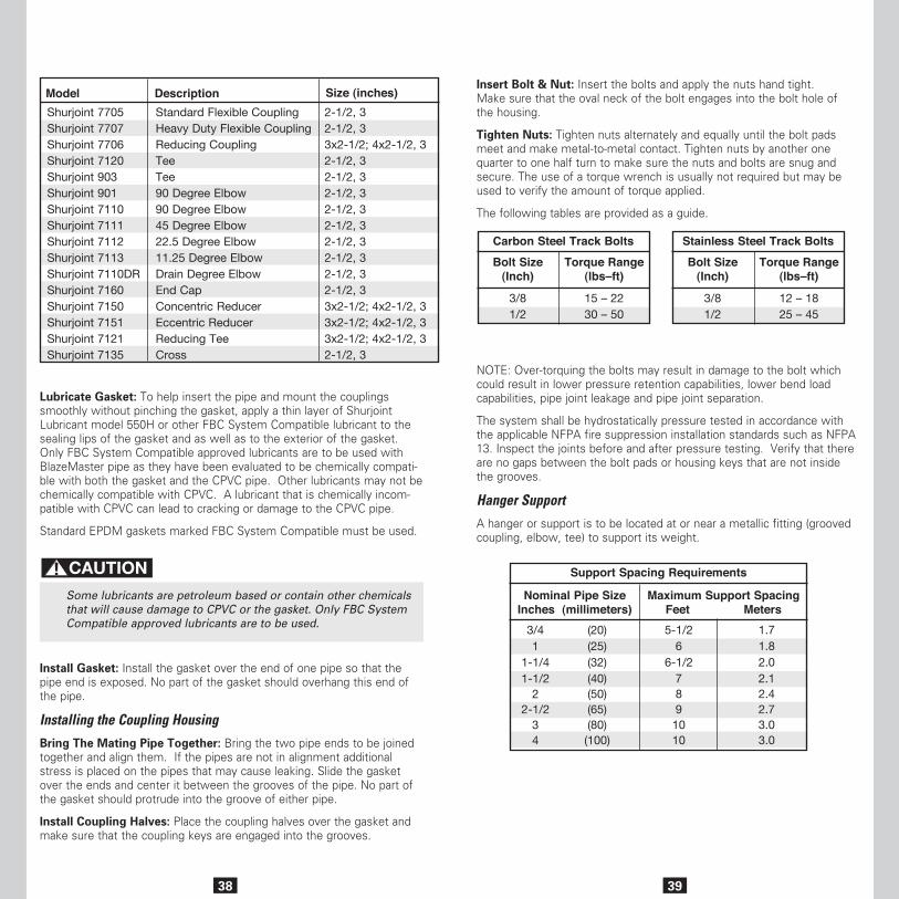
3938
Lubricate Gasket: To help insert the pipe and mount the couplings smoothly without pinching the gasket, apply a thin layer of Shurjoint Lubricant model 550H or other FBC System Compatible lubricant to the sealing lips of the gasket and as well as to the exterior of the gasket. Only FBC System Compatible approved lubricants are to be used with BlazeMaster pipe as they have been evaluated to be chemically compati-ble with both the gasket and the CPVC pipe. Other lubricants may not be chemically compatible with CPVC. A lubricant that is chemically incom-patible with CPVC can lead to cracking or damage to the CPVC pipe.
Standard EPDM gaskets marked FBC System Compatible must be used.
Some lubricants are petroleum based or contain other chemicals that will cause damage to CPVC or the gasket. Only FBC System Compatible approved lubricants are to be used.
Install Gasket: Install the gasket over the end of one pipe so that the pipe end is exposed. No part of the gasket should overhang this end of the pipe.
Installing the Coupling Housing
Bring The Mating Pipe Together: Bring the two pipe ends to be joined together and align them. If the pipes are not in alignment additional stress is placed on the pipes that may cause leaking. Slide the gasket over the ends and center it between the grooves of the pipe. No part of the gasket should protrude into the groove of either pipe.
Install Coupling Halves: Place the coupling halves over the gasket and make sure that the coupling keys are engaged into the grooves.
Model Description Size (inches)Shurjoint 7705Shurjoint 7707Shurjoint 7706Shurjoint 7120Shurjoint 903Shurjoint 901Shurjoint 7110Shurjoint 7111Shurjoint 7112Shurjoint 7113Shurjoint 7110DRShurjoint 7160Shurjoint 7150Shurjoint 7151Shurjoint 7121Shurjoint 7135
Standard Flexible Coupling Heavy Duty Flexible Coupling Reducing CouplingTeeTee90 Degree Elbow90 Degree Elbow45 Degree Elbow22.5 Degree Elbow11.25 Degree ElbowDrain Degree ElbowEnd CapConcentric ReducerEccentric ReducerReducing TeeCross
2-1/2, 32-1/2, 33x2-1/2; 4x2-1/2, 32-1/2, 3 2-1/2, 32-1/2, 32-1/2, 32-1/2, 32-1/2, 32-1/2, 32-1/2, 32-1/2, 33x2-1/2; 4x2-1/2, 33x2-1/2; 4x2-1/2, 33x2-1/2; 4x2-1/2, 32-1/2, 3
Insert Bolt & Nut: Insert the bolts and apply the nuts hand tight. Make sure that the oval neck of the bolt engages into the bolt hole of the housing.
Tighten Nuts: Tighten nuts alternately and equally until the bolt pads meet and make metal-to-metal contact. Tighten nuts by another one quarter to one half turn to make sure the nuts and bolts are snug and secure. The use of a torque wrench is usually not required but may be used to verify the amount of torque applied.
The following tables are provided as a guide.
NOTE: Over-torquing the bolts may result in damage to the bolt which could result in lower pressure retention capabilities, lower bend load capabilities, pipe joint leakage and pipe joint separation.
The system shall be hydrostatically pressure tested in accordance with the applicable NFPA fire suppression installation standards such as NFPA 13. Inspect the joints before and after pressure testing. Verify that there are no gaps between the bolt pads or housing keys that are not inside the grooves.
Hanger Support
A hanger or support is to be located at or near a metallic fitting (grooved coupling, elbow, tee) to support its weight.
Torque Range(lbs–ft)
Torque Range(lbs–ft)
Bolt Size(Inch)
Bolt Size(Inch)
Carbon Steel Track Bolts Stainless Steel Track Bolts
3/81/2
3/81/2
15 – 2230 – 50
12 – 1825 – 45
Support Spacing Requirements
Nominal Pipe SizeInches (millimeters)
Maximum Support SpacingFeet Meters
3/41
1-1/41-1/2
22-1/2
34
(20)(25)(32)(40)(50)(65)(80)(100)
5-1/26
6-1/27891010
1.71.82.02.12.42.73.03.0
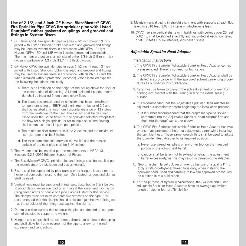
40
Use of 2-1/2, and 3 inch GF Harvel BlazeMaster® CPVC Fire Sprinkler Pipe CPVC fire sprinkler pipe with Listed Shurjoint® rubber gasketed couplings and grooved end fittings in System Risers
1. GF Harvel CPVC fire sprinkler pipe in sizes 2-1/2 inch through 3 inch, joined with Listed Shurjoint rubber-gasketed and grooved end fittings may be used as system risers in accordance with NFPA 13 Light Hazard, NFPA 13D and 13R when installed protected (concealed). The minimum protection shall consist of either 3/8 inch (9.5 mm) thick gypsum wallboard or 1/2 inch (12.7 mm) thick plywood.
2. GF Harvel CPVC fire sprinkler pipe in sizes 2-1/2 inch through 3 inch, joined with Listed Shurjoint rubber-gasketed and grooved end fittings, may be used as system risers in accordance with NFPA 13D and 13R when installed without protection (exposed). When installed exposed, the following limitations shall apply:
a. There is no limitation on the height of the ceiling above the riser or the construction of the ceiling. A Listed residential pendent sprin-kler shall be installed 7 feet above every floor.
b. The Listed residential pendent sprinkler shall have a maximum temperature rating of 155°F and a minimum K-factor of 3.0 and shall be installed at a maximum horizontal distance of 12 inches from the centerline of the riser. The system shall be designed based upon the Listed flows for the sprinkler selected except that the flow for a single sprinkler or for multiple sprinklers flowing shall be not less than 11 gpm per sprinkler.
c. The minimum riser diameter shall be 2 inches. and the maximum riser diameter shall be 3 inches.
d. The maximum distance between the wall(s) and the outside surface of the riser pipe shall be 3-1⁄4 inches.
3. The system shall be installed per the requirements of NFPA 13, Sections 9.2.5 (2010 Edition), Support of Risers.
4. The BlazeMaster® CPVC sprinkler pipe and fittings shall be installed per the manufacturer's installation and design manual.
5. Risers shall be supported by pipe clamps or by hangers located on the horizontal connection close to the riser. Only Listed hangers and clamps shall be used.
6. Vertical lines must be supported at intervals, described in 7 & 8 below, to avoid placing excessive load on a fitting at the lower end. Do this by using riser clamps or double bolt pipe clamps Listed for this service. The clamps must not exert compressive stresses on the pipe. It is recommended that the clamps should be located just below a fitting so that the shoulder of the fitting rests against the clamp.
7. Do not use riser clamps that squeeze the pipe and depend on compres-sion of the pipe to support the weight.
8. Hangers and straps shall not compress, distort, cut or abrade the piping and shall allow for free movement of the pipe to allow for thermal expansion and contraction.
41
Adjustable Sprinkler Head Adapter
Installation Instructions1. The CPVC Fire Sprinkler Adjustable Sprinkler Head Adapter comes
pre-assembled. There is no need for lubrication.
2. The CPVC Fire Sprinkler Adjustable Sprinkler Head Adapter shall be installed in accordance with the approved solvent cementing proce-dures as outlined in this publication.
3. Care must be taken to prevent the solvent cement or primer from coming into contact with the O-Ring seal or the inside sealing surface.
a. It is recommended that the Adjustable Sprinkler Head Adapter be adjusted out completely before beginning the installation process.
b. It is further recommended that the drop/riser pipe be solvent cemented into the Adjustable Sprinkler Head Adapter first and then into the drop/riser tee or elbow.
4. The CPVC Fire Sprinkler Adjustable Sprinkler Head Adapter has two wrench flats provided to hold the adjustment barrel while installing the sprinkler head. These same wrench flats shall be used to adjust the Sprinkler Head Adapter to its required position.
a. Never use wrenches, pliers or any other tool on the threaded portion of the adjustment barrel.
b. Caution shall be taken not to extend or retract the adjustment barrel excessively, as this may result in damaging the Adapter.
5. Georg Fischer Harvel LLC recommends the use of a quality PTFE (polytetrafluoroethylene) thread tape only, when installing the sprinkler head. Read and carefully follow the approved procedures as outlined in this publication.
6. For the purpose of hydraulic calculations, the 3/4 inch and 1 inch Adjustable Sprinkler Head Adapters have an average equivalent length of pipe in feet of .75’ (3/4 ft.)
9. Maintain vertical piping in straight alignment with supports at each floor level, or at 10 feet (3.05 m) intervals, whichever is less.
10. CPVC risers in vertical shafts or in buildings with ceilings over 25 feet (7.62 m), shall be aligned straightly and supported at each floor level, or at 10 feet (3.05 m) intervals, whichever is less.
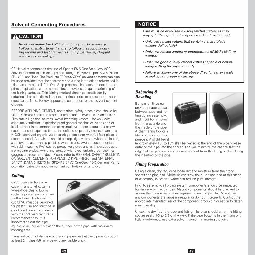
42
Solvent Cementing Procedures
Read and understand all instructions prior to assembly. Follow all instructions. Failure to follow instructions dur-ing joining and testing may result in pipe failure, clogged waterways, or leakage.
GF Harvel recommends the use of Spears FS-5 One-Step Low VOC Solvent Cement to join the pipe and fittings. However, Ipex BM-5, Nibco FP-1000, and Tyco Fire Products TFP-500 CPVC solvent cements can also be used provided that the assembly and curing instructions referenced in this manual are used. The One-Step process eliminates the need of the primer application, as the cement itself provides adequate softening of the joining surfaces. This joining method simplifies installation by reducing labor and offers faster curing times prior to pressure testing in most cases. Note: Follow appropriate cure times for the solvent cement chosen.
BEFORE APPLYING CEMENT, appropriate safety precautions should be taken. Cement should be stored in the shade between 40°F and 110°F. Eliminate all ignition sources. Avoid breathing vapors. Use only with adequate ventilation; explosion-proof general mechanical ventilation or local exhaust is recommended to maintain vapor concentrations below recommended exposure limits. In confined or partially enclosed areas, a NIOSH-approved organic vapor cartridge respirator with full face-piece is recommended. Containers should be kept tightly closed when not in use, and covered as much as possible when in use. Avoid frequent contact with skin; wearing PVA coated protective gloves and an impervious apron are recommended. Avoid any contact with eyes; splash proof chemical goggles are recommended. (Please refer to GENERAL SAFETY BULLETIN ON SOLVENT CEMENTS FOR PLASTIC PIPE - HFS-2, and MATERIAL SAFETY DATA SHEETS for SPEARS CPVC One-Step FS-5 Cement. Verify expiration dates stamped on cement can bottom prior to use.)
CuttingCPVC pipe can be easily cut with a ratchet cutter, a wheel-type plastic tubing cutter, a power saw or a fine toothed saw. Tools used to cut CPVC must be designed for plastic use and must be in good condition in accordance with the tool manufacturer’s recommendations. It is important to cut the pipe square. A square cut provides the surface of the pipe with maximum bonding area.
If any indication of damage or cracking is evident at the pipe end, cut off at least 2 inches (50 mm) beyond any visible crack.
43
NOTICECare must be exercised if using ratchet cutters as they may split the pipe if not properly used and maintained.
• Only use ratchet cutters that contain a sharp blade (blades dull quickly)
• Only use ratchet cutters at temperatures of 50°F (10°C) or warmer
• Only use good quality ratchet cutters capable of consis-tently cutting the pipe squarely
• Failure to follow any of the above directions may result in leakage or property damage
Deburring & Beveling Burrs and filings can prevent proper contact between pipe and fit-ting during assembly, and must be removed from the outside and the inside of the pipe. A chamfering tool or a file is suitable for this purpose. A slight bevel (approximately 10° to 15°) shall be placed at the end of the pipe to ease entry of the pipe into the socket. This will minimize the chance that the edges of the pipe will wipe solvent cement from the fitting socket during the insertion of the pipe.
Fitting PreparationUsing a clean, dry rag, wipe loose dirt and moisture from the fitting socket and pipe end. Moisture can slow the cure time, and at this stage of assembly, excessive water can reduce joint strength.
Prior to assembly, all piping system components should be inspected for damage or irregularities. Mating components should be checked to assure that tolerances and engagements are compatible. Do not use any components that appear irregular or do not fit properly. Contact the appropriate manufacturer of the component product in question to deter-mine usability.
Check the dry fit of the pipe and fitting. The pipe should enter the fitting socket easily 1/3 to 2/3 of the way. If the pipe bottoms in the fitting with little interference, use extra solvent cement in making the joint.
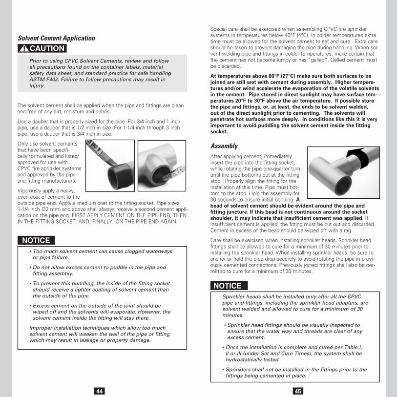
44
Solvent Cement Application
Prior to using CPVC Solvent Cements, review and follow all precautions found on the container labels, material safety data sheet, and standard practice for safe handling ASTM F402. Failure to follow precautions may result in injury.
The solvent cement shall be applied when the pipe and fittings are clean and free of any dirt, moisture and debris.
Use a dauber that is properly sized for the pipe. For 3/4 inch and 1 inch pipe, use a dauber that is 1/2 inch in size. For 1-1/4 inch through 3 inch pipe, use a dauber that is 3/4 inch in size.
Only use solvent cements that have been specifi-cally formulated and listed/ approved for use with CPVC fire sprinkler systems and approved by the pipe and fitting manufacturers.
Vigorously apply a heavy, even coat of cement to the outside pipe end. Apply a medium coat to the fitting socket. Pipe sizes 1-1/4 inch (32 mm) and above shall always receive a second cement appli-cation on the pipe end. FIRST APPLY CEMENT ON THE PIPE END, THEN IN THE FITTING SOCKET, AND, FINALLY, ON THE PIPE END AGAIN.
NOTICE• Too much solvent cement can cause clogged waterways
or pipe failure.
• Do not allow excess cement to puddle in the pipe and fitting assembly.
• To prevent this puddling, the inside of the fitting socket should receive a lighter coating of solvent cement than the outside of the pipe.
• Excess cement on the outside of the joint should be wiped off and the solvents will evaporate. However, the solvent cement inside the fitting will stay there.
Improper installation techniques which allow too much solvent cement will weaken the wall of the pipe or fitting which may result in leakage or property damage.
45
Special care shall be exercised when assembling CPVC fire sprinkler systems in temperatures below 40°F (4°C). In colder temperatures extra time must be allowed for the solvent cement to set and cure. Extra care should be taken to prevent damaging the pipe during handling. When sol-vent welding pipe and fittings in colder temperatures, make certain that the cement has not become lumpy or has “gelled”. Gelled cement must be discarded.
At temperatures above 80°F (27°C) make sure both surfaces to be joined are still wet with cement during assembly. Higher tempera-tures and/or wind accelerate the evaporation of the volatile solvents in the cement. Pipe stored in direct sunlight may have surface tem-peratures 20°F to 30°F above the air temperature. If possible store the pipe and fittings, or, at least, the ends to be solvent welded, out of the direct sunlight prior to cementing. The solvents will penetrate hot surfaces more deeply. In conditions like this it is very important to avoid puddling the solvent cement inside the fitting socket.
AssemblyAfter applying cement, immediately insert the pipe into the fitting socket, while rotating the pipe one-quarter turn until the pipe bottoms out at the fitting stop. Properly align the fitting for the installation at this time. Pipe must bot-tom to the stop. Hold the assembly for 30 seconds to ensure initial bonding. A bead of solvent cement should be evident around the pipe and fitting juncture. If this bead is not continuous around the socket shoulder, it may indicate that insufficient cement was applied. If insufficient cement is applied, the fitting must be cut out and discarded. Cement in excess of the bead should be wiped off with a rag.
Care shall be exercised when installing sprinkler heads. Sprinkler head fittings shall be allowed to cure for a minimum of 30 minutes prior to installing the sprinkler head. When installing sprinkler heads, be sure to anchor or hold the pipe drop securely to avoid rotating the pipe in previ-ously cemented connections. Previously joined fittings shall also be per-mitted to cure for a minimum of 30 minutes.
NOTICESprinkler heads shall be installed only after all the CPVC pipe and fittings, including the sprinkler head adapters, are solvent welded and allowed to cure for a minimum of 30 minutes.
• Sprinkler head fittings should be visually inspected to ensure that the water way and threads are clear of any excess cement.
• Once the installation is complete and cured per Table I, II or III (under Set and Cure Times), the system shall be hydrostatically tested.
• Sprinklers shall not be installed in the fittings prior to the fittings being cemented in place.
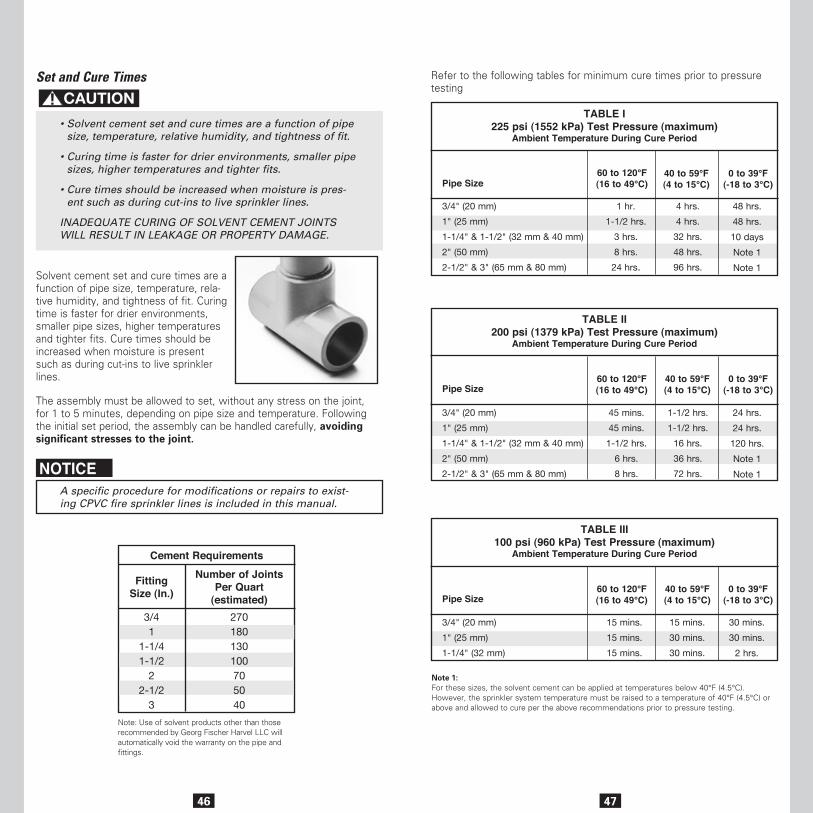
46
Set and Cure Times
• Solvent cement set and cure times are a function of pipe size, temperature, relative humidity, and tightness of fit.
• Curing time is faster for drier environments, smaller pipe sizes, higher temperatures and tighter fits.
• Cure times should be increased when moisture is pres-ent such as during cut-ins to live sprinkler lines.
INADEQUATE CURING OF SOLVENT CEMENT JOINTS WILL RESULT IN LEAKAGE OR PROPERTY DAMAGE.
Solvent cement set and cure times are a function of pipe size, temperature, rela-tive humidity, and tightness of fit. Curing time is faster for drier environments, smaller pipe sizes, higher temperatures and tighter fits. Cure times should be increased when moisture is present such as during cut-ins to live sprinkler lines.
The assembly must be allowed to set, without any stress on the joint, for 1 to 5 minutes, depending on pipe size and temperature. Following the initial set period, the assembly can be handled carefully, avoiding significant stresses to the joint.
NOTICEA specific procedure for modifications or repairs to exist-ing CPVC fire sprinkler lines is included in this manual.
Cement Requirements
FittingSize (In.)
Number of JointsPer Quart
(estimated)3/41
1-1/41-1/2
22-1/2
3
270180130100705040
Note: Use of solvent products other than those recommended by Georg Fischer Harvel LLC will automatically void the warranty on the pipe and fittings.
47
Refer to the following tables for minimum cure times prior to pressure testing
Pipe Size
3/4" (20 mm)
1" (25 mm)
1-1/4" & 1-1/2" (32 mm & 40 mm)
2" (50 mm)
2-1/2" & 3" (65 mm & 80 mm)
1 hr.
1-1/2 hrs.
3 hrs.
8 hrs.
24 hrs.
4 hrs.
4 hrs.
32 hrs.
48 hrs.
96 hrs.
48 hrs.
48 hrs.
10 days
Note 1
Note 1
60 to 120°F(16 to 49°C)
40 to 59°F(4 to 15°C)
0 to 39°F(-18 to 3°C)
TABLE I225 psi (1552 kPa) Test Pressure (maximum)
Ambient Temperature During Cure Period
Pipe Size
3/4" (20 mm)
1" (25 mm)
1-1/4" & 1-1/2" (32 mm & 40 mm)
2" (50 mm)
2-1/2" & 3" (65 mm & 80 mm)
45 mins.
45 mins.
1-1/2 hrs.
6 hrs.
8 hrs.
1-1/2 hrs.
1-1/2 hrs.
16 hrs.
36 hrs.
72 hrs.
24 hrs.
24 hrs.
120 hrs.
Note 1
Note 1
60 to 120°F(16 to 49°C)
40 to 59°F(4 to 15°C)
0 to 39°F(-18 to 3°C)
TABLE II200 psi (1379 kPa) Test Pressure (maximum)
Ambient Temperature During Cure Period
Pipe Size
3/4" (20 mm)
1" (25 mm)
1-1/4" (32 mm)
15 mins.
15 mins.
15 mins.
15 mins.
30 mins.
30 mins.
30 mins.
30 mins.
2 hrs.
60 to 120°F(16 to 49°C)
40 to 59°F(4 to 15°C)
0 to 39°F(-18 to 3°C)
TABLE III100 psi (960 kPa) Test Pressure (maximum)
Ambient Temperature During Cure Period
Note 1: For these sizes, the solvent cement can be applied at temperatures below 40°F (4.5°C).However, the sprinkler system temperature must be raised to a temperature of 40°F (4.5°C) or above and allowed to cure per the above recommendations prior to pressure testing.
48
System Acceptance Testing (Hydrostatic Pressure Test)Once an installation is completed and joints are properly cured, the system should be pressure tested with water at 200 psi (1379 kPa) for 2 hours. See Table II under Set and Cure Times for curing conditions at 200 psi (1379 kPa).
The system should be pressure tested with water at 50 psi (345 kPa) in excess of maximum pressure when the maximum system pressure is to be maintained in excess of 150 psi (1034 kPa). See Table I under Set and Cure Times for curing conditions at 225 psi (1552 kPa). This is in accor-dance with the requirements established by NFPA Standard 13, Section 24.2.1 (2007 Edition).
Sprinkler systems in one- and two-family dwellings and mobile homes may be pressure tested with water at line pressure, after following Table III under Set and Cure Times curing conditions, in accordance with the requirements established by NFPA 13D, Section 4.3 (2007 Edition).
When pressure testing, the sprinkler system shall be slowly filled with water and the air bled from the highest and farthest sprinkler heads before pressure testing is applied. Air must be removed from piping systems (plastic or metal) to prevent it from being locked in the system when pressure is applied. Entrapped air can generate excessive surge pressures that can result in bodily injury and/or property damage, regardless of the piping materials used.
If a leak is found, the fitting must be cut out and discarded. A new sec-tion can be installed using couplings or a union. Unions should be used in accessible areas only.
AIR OR COMPRESSED GAS MUST NEVER BE USED FOR SYSTEM ACCEPTANCE TESTING (HYDROSTATIC PRESSURE TEST). SYSTEM FAILURE WHEN USING COMPRESSED AIR/GAS FOR SYSTEM ACCEPTANCE TESTING CAN RESULT IN BODILY INJURY, DEATH AND/OR PROPERTY DAMAGE
49
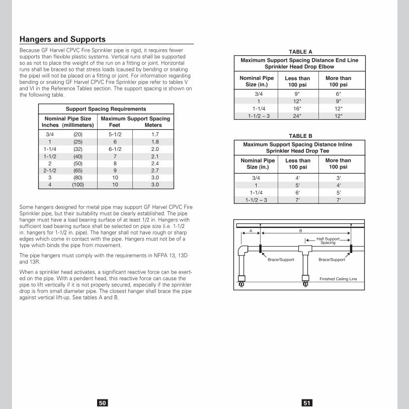
50
Hangers and SupportsBecause GF Harvel CPVC Fire Sprinkler pipe is rigid, it requires fewer supports than flexible plastic systems. Vertical runs shall be supported so as not to place the weight of the run on a fitting or joint. Horizontal runs shall be braced so that stress loads (caused by bending or snaking the pipe) will not be placed on a fitting or joint. For information regarding bending or snaking GF Harvel CPVC Fire Sprinkler pipe refer to tables V and VI in the Reference Tables section. The support spacing is shown on the following table.
Some hangers designed for metal pipe may support GF Harvel CPVC Fire Sprinkler pipe, but their suitability must be clearly established. The pipe hanger must have a load bearing surface of at least 1/2 in. Hangers with sufficient load bearing surface shall be selected on pipe size (i.e. 1-1/2 in. hangers for 1-1/2 in. pipe). The hanger shall not have rough or sharp edges which come in contact with the pipe. Hangers must not be of a type which binds the pipe from movement.
The pipe hangers must comply with the requirements in NFPA 13, 13D and 13R.
When a sprinkler head activates, a significant reactive force can be exert-ed on the pipe. With a pendent head, this reactive force can cause the pipe to lift vertically if it is not properly secured, especially if the sprinkler drop is from small diameter pipe. The closest hanger shall brace the pipe against vertical lift-up. See tables A and B.
51
3/41
1-1/41-1/2 – 3
Nominal PipeSize (in.)
Maximum Support Spacing Distance InlineSprinkler Head Drop Tee
Less than100 psi
More than100 psi
4'5'6'7'
3' 4' 5'7'
Maximum Support Spacing Distance End LineSprinkler Head Drop Elbow
Nominal PipeSize (in.)
3/41
1-1/41-1/2 – 3
9"12"16"24"
6"9"12"12"
Less than100 psi
More than100 psi
TABLE A
TABLE B
Half SupportSpacing
Brace/Support Brace/Support
Finished Ceiling Line
BA
Support Spacing Requirements
Nominal Pipe SizeInches (millimeters)
Maximum Support SpacingFeet Meters
3/41
1-1/41-1/2
22-1/2
34
(20)(25)(32)(40)(50)(65)(80)(100)
5-1/26
6-1/27891010
1.71.82.02.12.42.73.03.0
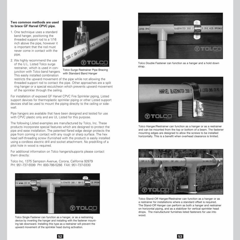
52
Two common methods are used to brace GF Harvel CPVC pipe.
1. One technique uses a standard band hanger, positioning the threaded support rod to a 1/16 inch above the pipe, however it is important that the rod must never come in contact with the pipe.
2. We highly recommend the use of the U.L. Listed Tolco surge restrainer, which is used in con-junction with Tolco band hangers. This easily installed combination restricts the upward movement of the pipe while not allowing the threaded support rod to contact the pipe. Other approaches are a split ring hanger or a special escutcheon which prevents upward movement of the sprinkler through the ceiling.
For installation of exposed GF Harvel CPVC Fire Sprinkler piping, Listed support devices for thermoplastic sprinkler piping or other Listed support devices shall be used to mount the piping directly to the ceiling or side-wall.
Pipe hangers are available that have been designed and tested for use with CPVC plastic only and are UL Listed for this purpose.
The following Listed examples are manufactured by Tolco, Inc. These products incorporate special features which are designed to protect the pipe and ease installation. The patented flared edge design protects the pipe from coming in contact with any rough or sharp surface. The hex head self-threading screw (furnished with the product) is easily installed using a cordless electric drill and socket attachment. No predrilling of a pilot hole in wood is required.
For additional information on Tolco hangers/supports please contact them directly:
Tolco Inc, 1375 Sampson Avenue, Corona, California 92879 PH: 951-737-5599 PH: 800-786-5266 FAX: 951-737-0330
Tolco Surge Restrainer Pipe Bracing with Standard Band Hanger
Tolco Single Fastener can function as a hanger, or as a restraining device by inverting the hanger and installing with the fastener mount-ing tab downward. Installing this type as a restrainer will prevent the upward movement of the sprinkler head during activation.
53
Tolco Double Fastener can function as a hanger and a hold down strap.
Tolco Hanger/Restrainer can function as a hanger or as a restrainer and can be mounted from the top or bottom of a beam. The fastener mounting edges are designed to allow the screws to be installed horizontally. This is a benefit when overhead clearance is limited.
Tolco Stand-Off Hanger/Restrainer can function as a hanger or as a restrainer for installations where a standard offset is required. The Stand-Off Hanger can perform as both a hanger and restrainer on horizontal piping, and as a stabilizer for vertical sprinkler head drops. The manufacturer furnishes listed fasteners for use into wood.
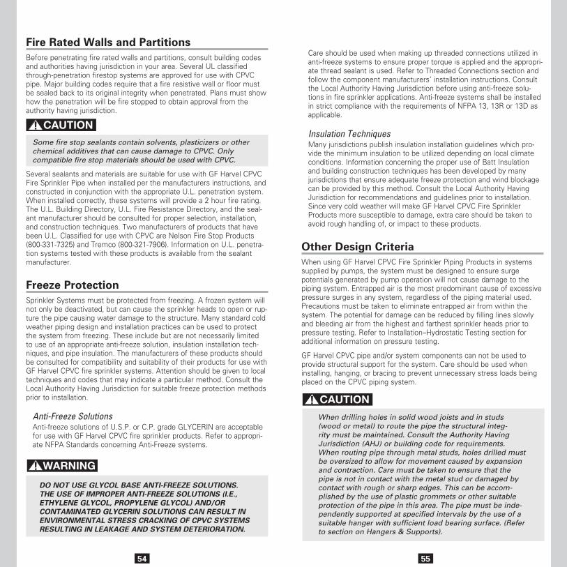
54
Fire Rated Walls and Partitions Before penetrating fire rated walls and partitions, consult building codes and authorities having jurisdiction in your area. Several UL classified through-penetration firestop systems are approved for use with CPVC pipe. Major building codes require that a fire resistive wall or floor must be sealed back to its original integrity when penetrated. Plans must show how the penetration will be fire stopped to obtain approval from the authority having jurisdiction.
Some fire stop sealants contain solvents, plasticizers or other chemical additives that can cause damage to CPVC. Only compatible fire stop materials should be used with CPVC.
Several sealants and materials are suitable for use with GF Harvel CPVC Fire Sprinkler Pipe when installed per the manufacturers instructions, and constructed in conjunction with the appropriate U.L. penetration system. When installed correctly, these systems will provide a 2 hour fire rating. The U.L. Building Directory, U.L. Fire Resistance Directory, and the seal-ant manufacturer should be consulted for proper selection, installation, and construction techniques. Two manufacturers of products that have been U.L. Classified for use with CPVC are Nelson Fire Stop Products (800-331-7325) and Tremco (800-321-7906). Information on U.L. penetra-tion systems tested with these products is available from the sealant manufacturer.
Freeze ProtectionSprinkler Systems must be protected from freezing. A frozen system will not only be deactivated, but can cause the sprinkler heads to open or rup-ture the pipe causing water damage to the structure. Many standard cold weather piping design and installation practices can be used to protect the system from freezing. These include but are not necessarily limited to use of an appropriate anti-freeze solution, insulation installation tech-niques, and pipe insulation. The manufacturers of these products should be consulted for compatibility and suitability of their products for use with GF Harvel CPVC fire sprinkler systems. Attention should be given to local techniques and codes that may indicate a particular method. Consult the Local Authority Having Jurisdiction for suitable freeze protection methods prior to installation.
Anti-Freeze SolutionsAnti-freeze solutions of U.S.P. or C.P. grade GLYCERIN are acceptable for use with GF Harvel CPVC fire sprinkler products. Refer to appropri-ate NFPA Standards concerning Anti-Freeze systems.
DO NOT USE GLYCOL BASE ANTI-FREEZE SOLUTIONS. THE USE OF IMPROPER ANTI-FREEZE SOLUTIONS (I.E., ETHYLENE GLYCOL, PROPYLENE GLYCOL) AND/OR CONTAMINATED GLYCERIN SOLUTIONS CAN RESULT IN ENVIRONMENTAL STRESS CRACKING OF CPVC SYSTEMS RESULTING IN LEAKAGE AND SYSTEM DETERIORATION.
55
Care should be used when making up threaded connections utilized in anti-freeze systems to ensure proper torque is applied and the appropri-ate thread sealant is used. Refer to Threaded Connections section and follow the component manufacturers’ installation instructions. Consult the Local Authority Having Jurisdiction before using anti-freeze solu-tions in fire sprinkler applications. Anti-freeze systems shall be installed in strict compliance with the requirements of NFPA 13, 13R or 13D as applicable.
Insulation TechniquesMany jurisdictions publish insulation installation guidelines which pro-vide the minimum insulation to be utilized depending on local climate conditions. Information concerning the proper use of Batt Insulation and building construction techniques has been developed by many jurisdictions that ensure adequate freeze protection and wind blockage can be provided by this method. Consult the Local Authority Having Jurisdiction for recommendations and guidelines prior to installation. Since very cold weather will make GF Harvel CPVC Fire Sprinkler Products more susceptible to damage, extra care should be taken to avoid rough handling of, or impact to these products.
Other Design CriteriaWhen using GF Harvel CPVC Fire Sprinkler Piping Products in systems supplied by pumps, the system must be designed to ensure surge potentials generated by pump operation will not cause damage to the piping system. Entrapped air is the most predominant cause of excessive pressure surges in any system, regardless of the piping material used. Precautions must be taken to eliminate entrapped air from within the system. The potential for damage can be reduced by filling lines slowly and bleeding air from the highest and farthest sprinkler heads prior to pressure testing. Refer to Installation–Hydrostatic Testing section for additional information on pressure testing.
GF Harvel CPVC pipe and/or system components can not be used to provide structural support for the system. Care should be used when installing, hanging, or bracing to prevent unnecessary stress loads being placed on the CPVC piping system.
When drilling holes in solid wood joists and in studs (wood or metal) to route the pipe the structural integ-rity must be maintained. Consult the Authority Having Jurisdiction (AHJ) or building code for requirements. When routing pipe through metal studs, holes drilled must be oversized to allow for movement caused by expansion and contraction. Care must be taken to ensure that the pipe is not in contact with the metal stud or damaged by contact with rough or sharp edges. This can be accom-plished by the use of plastic grommets or other suitable protection of the pipe in this area. The pipe must be inde-pendently supported at specified intervals by the use of a suitable hanger with sufficient load bearing surface. (Refer to section on Hangers & Supports).
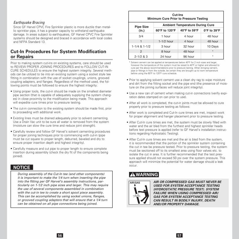
56
Earthquake BracingSince GF Harvel CPVC Fire Sprinkler plastic is more ductile than metal-lic sprinkler pipe, it has a greater capacity to withstand earthquake damage. In areas subject to earthquakes, GF Harvel CPVC Fire Sprinkler systems should be designed and braced in accordance with local codes and NFPA Standard 13.
Cut-In Procedures for System Modification or RepairsPrior to making system cut-ins on existing systems, care should be used to REVIEW PROPER JOINING PROCEDURES and to FOLLOW CUT-IN CURE SCHEDULES to ensure the highest system integrity. Several meth-ods can be utilized to tie into an existing system using a socket style tee fitting in combination with the use of socket couplings, unions, grooved coupling adapters, and flanges. Regardless of the method used, the fol-lowing points must be followed to ensure the highest integrity:
• Using proper tools, the cut-in should be made on the smallest diameter pipe section (that is capable of adequately supplying the system chang-es) in close proximity to the modification being made. This approach will expedite cure times prior to pressure testing.
• The cut-in connection to the existing system should be made first, prior to proceeding with additional work.
• Existing lines must be drained adequately prior to solvent cementing. Use a Drain Vac unit to be sure all water is removed from the system (moisture can slow the cure time and reduce joint strength).
• Carefully review and follow GF Harvel’s solvent cementing procedures for proper joining techniques prior to commencing with cut-in (pipe must be cut square to proper length, deburred, beveled and dry to ensure proper insertion depth and highest integrity).
• Carefully measure and cut pipe to proper length to ensure complete insertion during assembly (check the dry fit of the components being joined).
NOTICEDuring assembly of the Cut-In tee (and other components) it is important to make the 1/4 turn when inserting the pipe into the fitting per GF Harvel’s assembly instructions, par-ticularly on 1-1/2 inch pipe sizes and larger. This may require the use of several components assembled in combination with the cut-in tee to create a short spool piece assembly. This can be accomplished by using socket unions, flanges, or grooved coupling adapters that will ensure that a 1/4 turn can be obtained on all pipe connections being joined.
57
• Prior to applying solvent cement use a clean dry rag to wipe moisture and dirt from the fitting socket and the pipe end (the presence of mois-ture on the joining surfaces will reduce joint integrity).
• Use a new can of cement when making cut-in connections (verify expi-ration dates stamped on can prior to use).
• After all work is completed, the cut-in joints must be allowed to cure properly prior to pressure testing as follows:
• After work is completed and Cut-In cure times are met, inspect work for proper alignment and hanger placement prior to pressure testing.
• After Cut-In cure times are met, the system must be slowly filled with water and the air bled from the furthest and highest sprinkler heads before test pressure is applied (refer to GF Harvel’s installation instruc-tions regarding Hydrostatic Testing).
• After Cut-In cure times are met and the air is bled from the system, it is recommended that the portion of the sprinkler system containing the cut in tee be pressure tested. Prior to pressure testing, the system must be sectioned off to its smallest area using floor valves etc. to isolate the cut in area. It is further recommended that the test pres-sure applied should not exceed 50 psi over the system pressure. This approach will minimize the potential for water damage should a leak occur.
AIR OR COMPRESSED GAS MUST NEVER BE USED FOR SYSTEM ACCEPTANCE TESTING (HYDROSTATIC PRESSURE TEST). SYSTEM FAILURE WHEN USING COMPRESSED AIR/GAS FOR SYSTEM ACCEPTANCE TESTING CAN RESULT IN BODILY INJURY, DEATH AND/OR PROPERTY DAMAGE.
Pipe Size(in.)
Cut-InsMinimum Cure Prior to Pressure Testing
60°F to 120°F 40°F to 59°F 0°F to 39°F
3/4
1
1-1/4 & 1-1/2
2
2-1/2 & 3
1 hour
1-1/2 hour
3 hour
8 hour
24 hour
4 hour
4 hour
32 hour
48 hour
96 hour
48 hour
48 hour
10 Days
*
*
Ambient Temperature During Cure
* Solvent cement can be applied at temperatures below 40°F for 2 inch sizes and larger, however the temperature of the system must be raised to 40°F or higher and allowed to cure per the above recommendations prior to pressure testing. When bringing cement, pipe or fittings in from the outside, be certain they are brought up to room temperature before using the 60°F to 120°F cure schedule.
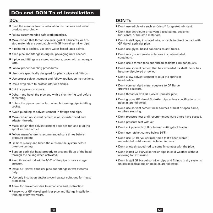
58
DOsn Read the manufacturer’s installation instructions and install
product accordingly.
n Follow recommended safe work practices.
n Make certain that thread sealants, gasket lubricants, or fire-stop materials are compatible with GF Harvel sprinkler pipe.
n If painting is desired, use only water-based latex paints.
n Keep pipe and fittings in original packaging until needed.
n If pipe and fittings are stored outdoors, cover with an opaque tarp.
n Follow proper handling procedures.
n Use tools specifically designed for plastic pipe and fittings.
n Use proper solvent cement and follow application instructions.
n Use a drop cloth to protect interior finishes.
n Cut the pipe ends square.
n Deburr and bevel the pipe end with a chamfering tool before cementing.
n Rotate the pipe a quarter turn when bottoming pipe in fitting socket.
n Avoid puddling of solvent cement in fittings and pipe.
n Make certain no solvent cement is on sprinkler head and adapter threads.
n Make certain that solvent cement does not run and plug the sprinkler head orifice.
n Follow manufacturer’s recommended cure times before pressure testing.
n Fill lines slowly and bleed the air from the system before pressure testing.
n Support sprinkler head properly to prevent lift up of the head through the ceiling when activated.
n Keep threaded rod within 1/16" of the pipe or use a surge arrestor.
n Install GF Harvel sprinkler pipe and fittings in wet systems only.
n Use only insulation and/or glycerin/water solutions for freeze protection.
n Allow for movement due to expansion and contraction.
n Renew your GF Harvel sprinkler pipe and fittings installation training every two years.
DOs and DON’Ts of Installation
59
DON’Tsn Don’t use edible oils such as Crisco® for gasket lubricant.
n Don’t use petroleum or solvent-based paints, sealants, lubricants, or fire-stop materials.
n Don’t install tape, insulated wire, or cable in direct contact with GF Harvel sprinkler pipe.
n Don’t use glycol-based solutions as anti-freeze.
n Don’t mix glycerin/water solutions in contaminated containers.
n Don’t use a thread tape and thread sealants simultaneously.
n Don’t use solvent cement that has exceeded its shelf life or has become discolored or gelled.
n Don’t allow solvent cement to plug the sprinkler head orifice.
n Don’t connect rigid metal couplers to GF Harvel grooved adaptors.
n Don’t thread or drill GF Harvel Sprinkler pipe.
n Don’t groove GF Harvel Sprinkler pipe unless specifications on page 35 are followed.
n Don’t use solvent cement near sources of heat or open flame, or when smoking.
n Don’t pressure-test until recommended cure times have passed.
n Don’t pressure test with air.
n Don’t cut pipe with dull or broken cutting-tool blades.
n Don’t use ratchet cutters below 50°F.
n Don’t use GF Harvel sprinkler pipe that’s been stored unprotected outdoors and is faded in color.
n Don’t allow threaded rod to come in contact with the pipe.
n Don’t install GF Harvel sprinkler pipe in cold weather without allowing for expansion.
n Don’t install GF Harvel sprinkler pipe and fittings in dry systems, unless specifications on page 26 are followed.
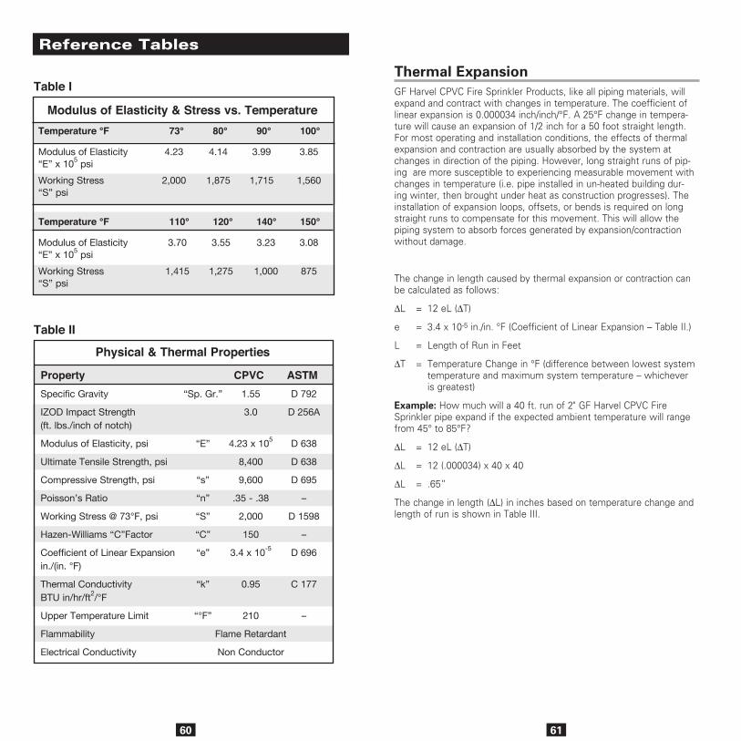
60
Modulus of Elasticity & Stress vs. Temperature
Property CPVC ASTMSpecific Gravity “Sp. Gr.” 1.55 D 792
IZOD Impact Strength 3.0 D 256A(ft. lbs./inch of notch)
Modulus of Elasticity, psi “E” 4.23 x 10⁵ D 638
Ultimate Tensile Strength, psi 8,400 D 638
Compressive Strength, psi “s” 9,600 D 695
Poisson’s Ratio “n” .35 - .38 –
Working Stress @ 73°F, psi “S” 2,000 D 1598
Hazen-Williams “C”Factor “C” 150 –
Coefficient of Linear Expansion “e” 3.4 x 10⁻⁵ D 696in./(in. °F)
Thermal Conductivity “k” 0.95 C 177BTU in/hr/ft2/°F
Upper Temperature Limit “°F” 210 –
Flammability Flame Retardant
Electrical Conductivity Non Conductor
Physical & Thermal Properties
Temperature °F 73° 80° 90° 100°
Modulus of Elasticity 4.23 4.14 3.99 3.85“E” x 105 psi
Working Stress 2,000 1,875 1,715 1,560“S” psi
Temperature °F 110° 120° 140° 150°
Modulus of Elasticity 3.70 3.55 3.23 3.08“E” x 105 psi
Working Stress 1,415 1,275 1,000 875“S” psi
Reference Tables
Table I
Table II
61
Thermal ExpansionGF Harvel CPVC Fire Sprinkler Products, like all piping materials, will expand and contract with changes in temperature. The coefficient of linear expansion is 0.000034 inch/inch/°F. A 25°F change in tempera-ture will cause an expansion of 1/2 inch for a 50 foot straight length. For most operating and installation conditions, the effects of thermal expansion and contraction are usually absorbed by the system at changes in direction of the piping. However, long straight runs of pip-ing are more susceptible to experiencing measurable movement with changes in temperature (i.e. pipe installed in un-heated building dur-ing winter, then brought under heat as construction progresses). The installation of expansion loops, offsets, or bends is required on long straight runs to compensate for this movement. This will allow the piping system to absorb forces generated by expansion/contraction without damage.
The change in length caused by thermal expansion or contraction can be calculated as follows:
∆L = 12 eL (∆T)
e = 3.4 x 10⁻⁵ in./in. °F (Coefficient of Linear Expansion – Table II.)
L = Length of Run in Feet
∆T = Temperature Change in °F (difference between lowest system temperature and maximum system temperature – whichever is greatest)
Example: How much will a 40 ft. run of 2" GF Harvel CPVC Fire Sprinkler pipe expand if the expected ambient temperature will range from 45° to 85°F?
∆L = 12 eL (∆T)
∆L = 12 (.000034) x 40 x 40
∆L = .65”
The change in length (∆L) in inches based on temperature change and length of run is shown in Table III.

= 3ED(∆L)2Sl
= 3ED(∆L)2Sl
62
Length of Run in Feet 5 10 15 20 25 30 35
20 .04 .08 .12 .16 .20 .24 .29
30 .06 .12 .24 .24 .31 .37 .43
40 .08 .16 .33 .41 .41 .49 .57
50 .10 .20 .41 .51 .51 .61 .72
60 .12 .24 .49 .61 .61 .73 .86
70 .19 .29 .57 .71 .71 .88 1.00
80 .16 .33 .65 .82 .82 .98 1.14
90 .18 .37 .73 .92 .92 1.10 1.29
100 .20 .41 .82 1.02 1.02 1.22 1.43
Temp. Change
∆T °F
Thermal Expansion in Inches
Thermal Expansion ∆L (In.)
Length of Run in Feet (cont.) 40 45 50 70 90 120 160
20 .33 .37 .41 .57 .73 .98 1.31
30 .49 .55 .61 .86 1.10 1.47 1.96
40 .65 .74 .82 1.14 1.47 1.96 2.61
50 .82 .92 1.02 1.43 1.84 2.45 3.26
60 .98 1.10 1.22 1.71 2.20 2.94 3.92
70 1.14 1.29 1.43 2.00 2.57 3.43 4.57
80 1.31 1.47 1.63 2.28 2.94 3.92 5.22
90 1.47 1.66 1.84 2.57 3.30 4.41 5.88
100 1.63 1.84 2.04 2.86 3.67 4.90 6.53
Temp. Change
∆T °F Thermal Expansion ∆L (In.)
Once the change in length (∆L) has been determined, the length of an offset, expansion loop, or bend required to compensate for this change can be calculated as follows:
= Length of Expansion Loop in inches
E = Modulus of Elasticity at 100°F (Table I)
D = Average O.D. of Pipe
∆L = Change in Length of Pipe Due to Change in Temperature (Table III)
S = Working Stress at 100°F (Table I)
Table III
7 11 13 15 17 18 20
8 12 14 17 19 20 22
9 13 16 19 21 23 25
10 14 20 22 22 25 27
11 16 19 22 25 27 30
12 18 21 25 27 30 33
13 19 24 27 30 33 36
Length of Run in Feet 5 10 15 20 25 30 35
NOTE: Table IV is based on Stress & Modulus of Elasticity @ 100°F
1.050
1.315
1.660
1.900
2.375
2.875
3.500
NominalPipe Size
(in.)
Avg.O.D. Length of Loop (In.)
Temperature = 30°F - 100°F ∆T = 70°F
3/4
1
1-1/4
1-1/2
2
2-1/2
3
21 22 24 28 32 37 42
24 25 26 31 35 41 47
26 28 30 35 40 46 53
28 30 32 38 43 49 57
32 34 35 42 48 55 63
35 37 39 46 52 60 70
38 41 43 51 58 67 77
1.050
1.315
1.660
1.900
2.375
2.875
3.500
NominalPipe Size
(in.)
Avg.O.D. Length of Loop (In.)
Temperature = 30°F - 100°F ∆T = 70°F
3/4
1
1-1/4
1-1/2
2
2-1/2
3
63
The length of an offset, expansion loop, or bend required to compensate for this movement ( l ) based on pipe size and length of run is shown in Table IV. These values are based on a temperature change (∆T) of 70°F which covers most installation temperature ranges.
Expansion Loop Length in Inches
Table IV
Length of Run in Feet (cont.) 40 45 50 70 90 120 160
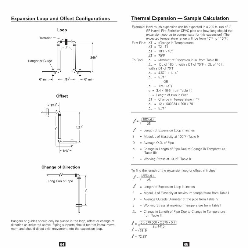
64
Expansion Loop and Offset Configurations
Hangers or guides should only be placed in the loop, offset or change of direction as indicated above. Piping supports should restrict lateral move-ment and should direct axial movement into the expansion loop.
Loop
Change of Direction
Offset
Hanger or Guide
Restraint
l
2/5 l
6" min.1/5 l6" min.
1/4 l
1/2 l
1/4 l
l
l
Long Run of Pipe
65
Example: How much expansion can be expected in a 200 ft. run of 2" GF Harvel Fire Sprinkler CPVC pipe and how long should the expansion loop be to compensate for this expansion? (The expected temperature range will be from 40°F to 110°F.)
First Find: ∆T = (Change in Temperature) ∆T = T2 - T1 ∆T = 10°F - 40°F ∆T = 70°FTo Find: ∆L = (Amount of Expansion in in. from Table III.) ∆L = DL of 160 ft. with a DT of 70°F + DL of 40 ft. with a DT of 70°F ∆L = 4.57” + 1.14” ∆L = 5.71” — OR — ∆L = 12eL (∆T) e = 3.4 x 10⁻⁵ (from Table II.) L = Length of Run in Feet ∆T = Change in Temperature in °F ∆L = 12 x .000034 x 200 x 70 ∆L = 5.71”
= Length of Expansion Loop in inches
E = Modulus of Elasticity at maximum temperature from Table I
D = Average Outside Diameter of the pipe from Table IV
S = Working Stress at maximum temperature from Table I
∆L = Change in Length of Pipe Due to Change in Temperature from Table III
To find the length of the expansion loop or offset in inches
l = 72.93"
l = 5319√
l = 3 x 370,000 x 2.375 x 5.712 x 1415
= 3ED(∆L)2Sl
= 3ED(∆L)2Sl
= 3ED(∆L)2Sl
= 3ED(∆L)2Sl
= Length of Expansion Loop in inches
E = Modulus of Elasticity at 100°F (Table I)
D = Average O.D. of Pipe
∆L = Change in Length of Pipe Due to Change in Temperature (Table III)
S = Working Stress at 100°F (Table I)
Thermal Expansion — Sample Calculation
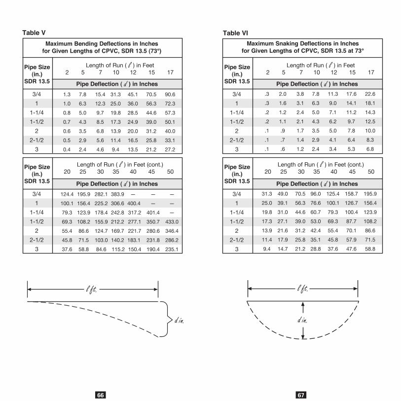
66
1.3 7.8 15.4 31.3 45.1 70.5 90.6
1.0 6.3 12.3 25.0 36.0 56.3 72.3
0.8 5.0 9.7 19.8 28.5 44.6 57.3
0.7 4.3 8.5 17.3 24.9 39.0 50.1
0.6 3.5 6.8 13.9 20.0 31.2 40.0
0.5 2.9 5.6 11.4 16.5 25.8 33.1
0.4 2.4 4.6 9.4 13.5 21.2 27.2
Length of Run ( l ) in Feet 2 5 7 10 12 15 17
Pipe Deflection ( d ) in Inches3/4
1
1-1/4
1-1/2
2
2-1/2
3
Pipe Size(in.)
SDR 13.5
124.4 195.9 282.1 383.9 — — —
100.1 156.4 225.2 306.6 400.4 — —
79.3 123.9 178.4 242.8 317.2 401.4 —
69.3 108.2 155.9 212.2 277.1 350.7 433.0
55.4 86.6 124.7 169.7 221.7 280.6 346.4
45.8 71.5 103.0 140.2 183.1 231.8 286.2
37.6 58.8 84.6 115.2 150.4 190.4 235.1
Pipe Deflection ( d ) in Inches3/4
1
1-1/4
1-1/2
2
2-1/2
3
Pipe Size(in.)
SDR 13.5
Maximum Bending Deflections in Inchesfor Given Lengths of CPVC, SDR 13.5 (73°)
Table V
Length of Run ( l ) in Feet (cont.) 20 25 30 35 40 45 50
67
Maximum Snaking Deflections in Inchesfor Given Lengths of CPVC, SDR 13.5 at 73°
.3 2.0 3.8 7.8 11.3 17.6 22.6
.3 1.6 3.1 6.3 9.0 14.1 18.1
.2 1.2 2.4 5.0 7.1 11.2 14.3
.2 1.1 2.1 4.3 6.2 9.7 12.5
.1 .9 1.7 3.5 5.0 7.8 10.0
.1 .7 1.4 2.9 4.1 6.4 8.3
.1 .6 1.2 2.4 3.4 5.3 6.8
Pipe Deflection ( d ) in Inches3/4
1
1-1/4
1-1/2
2
2-1/2
3
Pipe Size(in.)
SDR 13.5
31.3 49.0 70.5 96.0 125.4 158.7 195.9
25.0 39.1 56.3 76.6 100.1 126.7 156.4
19.8 31.0 44.6 60.7 79.3 100.4 123.9
17.3 27.1 39.0 53.0 69.3 87.7 108.2
13.9 21.6 31.2 42.4 55.4 70.1 86.6
11.4 17.9 25.8 35.1 45.8 57.9 71.5
9.4 14.7 21.2 28.8 37.6 47.6 58.8
Pipe Deflection ( d ) in Inches3/4
1
1-1/4
1-1/2
2
2-1/2
3
Pipe Size(in.)
SDR 13.5
Table VI
Length of Run ( l ) in Feet 2 5 7 10 12 15 17
Length of Run ( l ) in Feet (cont.) 20 25 30 35 40 45 50
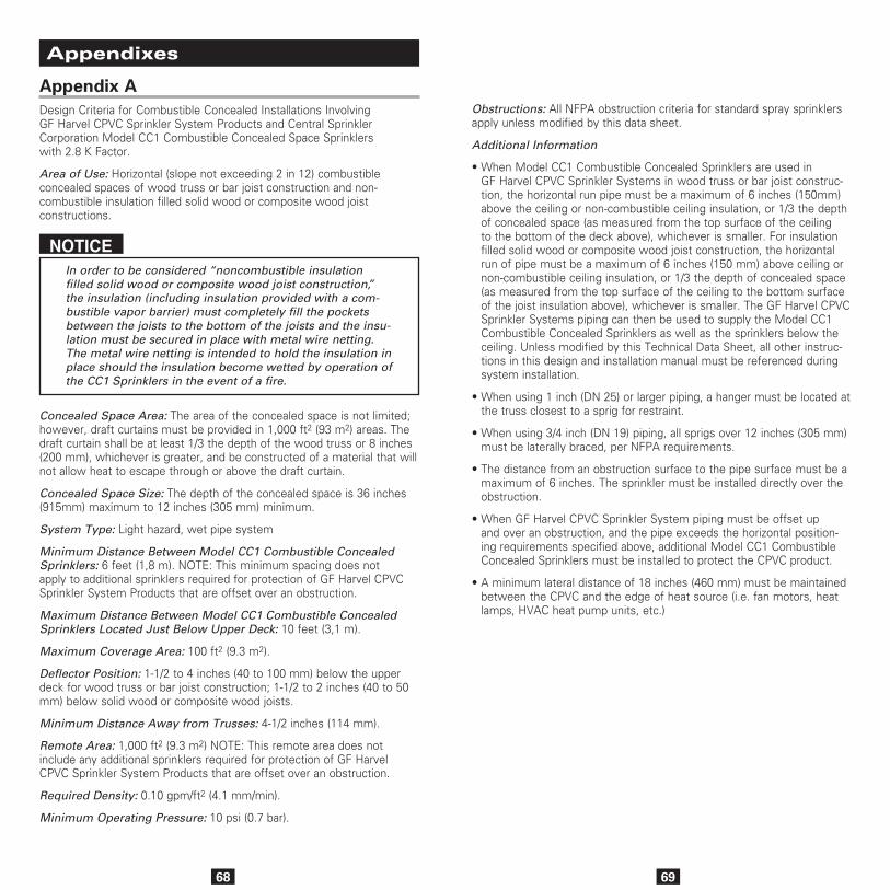
68
WARRANTY
Appendix ADesign Criteria for Combustible Concealed Installations Involving GF Harvel CPVC Sprinkler System Products and Central Sprinkler Corporation Model CC1 Combustible Concealed Space Sprinklers with 2.8 K Factor.
Area of Use: Horizontal (slope not exceeding 2 in 12) combustible concealed spaces of wood truss or bar joist construction and non- combustible insulation filled solid wood or composite wood joist constructions.
NOTICEIn order to be considered “noncombustible insulation filled solid wood or composite wood joist construction,” the insulation (including insulation provided with a com-bustible vapor barrier) must completely fill the pockets between the joists to the bottom of the joists and the insu-lation must be secured in place with metal wire netting. The metal wire netting is intended to hold the insulation in place should the insulation become wetted by operation of the CC1 Sprinklers in the event of a fire.
Concealed Space Area: The area of the concealed space is not limited; however, draft curtains must be provided in 1,000 ft2 (93 m2) areas. The draft curtain shall be at least 1/3 the depth of the wood truss or 8 inches (200 mm), whichever is greater, and be constructed of a material that will not allow heat to escape through or above the draft curtain.
Concealed Space Size: The depth of the concealed space is 36 inches (915mm) maximum to 12 inches (305 mm) minimum.
System Type: Light hazard, wet pipe system
Minimum Distance Between Model CC1 Combustible Concealed Sprinklers: 6 feet (1,8 m). NOTE: This minimum spacing does not apply to additional sprinklers required for protection of GF Harvel CPVC Sprinkler System Products that are offset over an obstruction.
Maximum Distance Between Model CC1 Combustible Concealed Sprinklers Located Just Below Upper Deck: 10 feet (3,1 m).
Maximum Coverage Area: 100 ft2 (9.3 m2).
Deflector Position: 1-1/2 to 4 inches (40 to 100 mm) below the upper deck for wood truss or bar joist construction; 1-1/2 to 2 inches (40 to 50 mm) below solid wood or composite wood joists.
Minimum Distance Away from Trusses: 4-1/2 inches (114 mm).
Remote Area: 1,000 ft2 (9.3 m2) NOTE: This remote area does not include any additional sprinklers required for protection of GF Harvel CPVC Sprinkler System Products that are offset over an obstruction.
Required Density: 0.10 gpm/ft2 (4.1 mm/min).
Minimum Operating Pressure: 10 psi (0.7 bar).
Appendixes
69
Obstructions: All NFPA obstruction criteria for standard spray sprinklers apply unless modified by this data sheet.
Additional Information
• When Model CC1 Combustible Concealed Sprinklers are used in GF Harvel CPVC Sprinkler Systems in wood truss or bar joist construc-tion, the horizontal run pipe must be a maximum of 6 inches (150mm) above the ceiling or non-combustible ceiling insulation, or 1/3 the depth of concealed space (as measured from the top surface of the ceiling to the bottom of the deck above), whichever is smaller. For insulation filled solid wood or composite wood joist construction, the horizontal run of pipe must be a maximum of 6 inches (150 mm) above ceiling or non-combustible ceiling insulation, or 1/3 the depth of concealed space (as measured from the top surface of the ceiling to the bottom surface of the joist insulation above), whichever is smaller. The GF Harvel CPVC Sprinkler Systems piping can then be used to supply the Model CC1 Combustible Concealed Sprinklers as well as the sprinklers below the ceiling. Unless modified by this Technical Data Sheet, all other instruc-tions in this design and installation manual must be referenced during system installation.
• When using 1 inch (DN 25) or larger piping, a hanger must be located at the truss closest to a sprig for restraint.
• When using 3/4 inch (DN 19) piping, all sprigs over 12 inches (305 mm) must be laterally braced, per NFPA requirements.
• The distance from an obstruction surface to the pipe surface must be a maximum of 6 inches. The sprinkler must be installed directly over the obstruction.
• When GF Harvel CPVC Sprinkler System piping must be offset up and over an obstruction, and the pipe exceeds the horizontal position-ing requirements specified above, additional Model CC1 Combustible Concealed Sprinklers must be installed to protect the CPVC product.
• A minimum lateral distance of 18 inches (460 mm) must be maintained between the CPVC and the edge of heat source (i.e. fan motors, heat lamps, HVAC heat pump units, etc.)
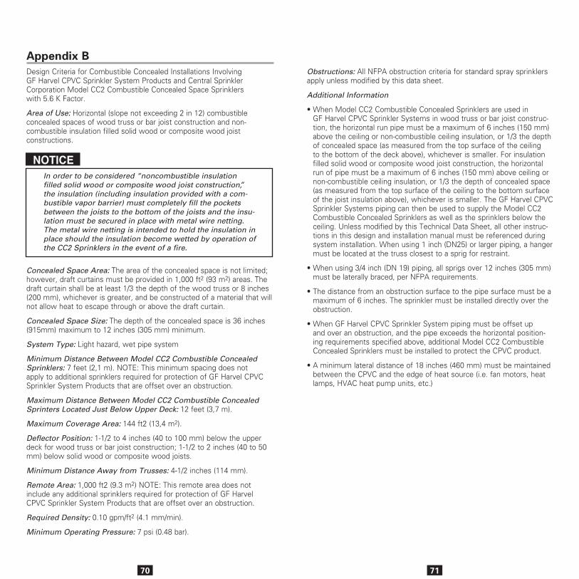
70
Appendix BDesign Criteria for Combustible Concealed Installations Involving GF Harvel CPVC Sprinkler System Products and Central Sprinkler Corporation Model CC2 Combustible Concealed Space Sprinklers with 5.6 K Factor.
Area of Use: Horizontal (slope not exceeding 2 in 12) combustible concealed spaces of wood truss or bar joist construction and non- combustible insulation filled solid wood or composite wood joist constructions.
NOTICEIn order to be considered “noncombustible insulation filled solid wood or composite wood joist construction,” the insulation (including insulation provided with a com-bustible vapor barrier) must completely fill the pockets between the joists to the bottom of the joists and the insu-lation must be secured in place with metal wire netting. The metal wire netting is intended to hold the insulation in place should the insulation become wetted by operation of the CC2 Sprinklers in the event of a fire.
Concealed Space Area: The area of the concealed space is not limited; however, draft curtains must be provided in 1,000 ft2 (93 m2) areas. The draft curtain shall be at least 1/3 the depth of the wood truss or 8 inches (200 mm), whichever is greater, and be constructed of a material that will not allow heat to escape through or above the draft curtain.
Concealed Space Size: The depth of the concealed space is 36 inches (915mm) maximum to 12 inches (305 mm) minimum.
System Type: Light hazard, wet pipe system
Minimum Distance Between Model CC2 Combustible Concealed Sprinklers: 7 feet (2,1 m). NOTE: This minimum spacing does not apply to additional sprinklers required for protection of GF Harvel CPVC Sprinkler System Products that are offset over an obstruction.
Maximum Distance Between Model CC2 Combustible Concealed Sprinters Located Just Below Upper Deck: 12 feet (3,7 m).
Maximum Coverage Area: 144 ft2 (13,4 m2).
Deflector Position: 1-1/2 to 4 inches (40 to 100 mm) below the upper deck for wood truss or bar joist construction; 1-1/2 to 2 inches (40 to 50 mm) below solid wood or composite wood joists.
Minimum Distance Away from Trusses: 4-1/2 inches (114 mm).
Remote Area: 1,000 ft2 (9.3 m2) NOTE: This remote area does not include any additional sprinklers required for protection of GF Harvel CPVC Sprinkler System Products that are offset over an obstruction.
Required Density: 0.10 gpm/ft2 (4.1 mm/min).
Minimum Operating Pressure: 7 psi (0.48 bar).
71
Obstructions: All NFPA obstruction criteria for standard spray sprinklers apply unless modified by this data sheet.
Additional Information
• When Model CC2 Combustible Concealed Sprinklers are used in GF Harvel CPVC Sprinkler Systems in wood truss or bar joist construc-tion, the horizontal run pipe must be a maximum of 6 inches (150 mm) above the ceiling or non-combustible ceiling insulation, or 1/3 the depth of concealed space (as measured from the top surface of the ceiling to the bottom of the deck above), whichever is smaller. For insulation filled solid wood or composite wood joist construction, the horizontal run of pipe must be a maximum of 6 inches (150 mm) above ceiling or non-combustible ceiling insulation, or 1/3 the depth of concealed space (as measured from the top surface of the ceiling to the bottom surface of the joist insulation above), whichever is smaller. The GF Harvel CPVC Sprinkler Systems piping can then be used to supply the Model CC2 Combustible Concealed Sprinklers as well as the sprinklers below the ceiling. Unless modified by this Technical Data Sheet, all other instruc-tions in this design and installation manual must be referenced during system installation. When using 1 inch (DN25) or larger piping, a hanger must be located at the truss closest to a sprig for restraint.
• When using 3/4 inch (DN 19) piping, all sprigs over 12 inches (305 mm) must be laterally braced, per NFPA requirements.
• The distance from an obstruction surface to the pipe surface must be a maximum of 6 inches. The sprinkler must be installed directly over the obstruction.
• When GF Harvel CPVC Sprinkler System piping must be offset up and over an obstruction, and the pipe exceeds the horizontal position-ing requirements specified above, additional Model CC2 Combustible Concealed Sprinklers must be installed to protect the CPVC product.
• A minimum lateral distance of 18 inches (460 mm) must be maintained between the CPVC and the edge of heat source (i.e. fan motors, heat lamps, HVAC heat pump units, etc.)
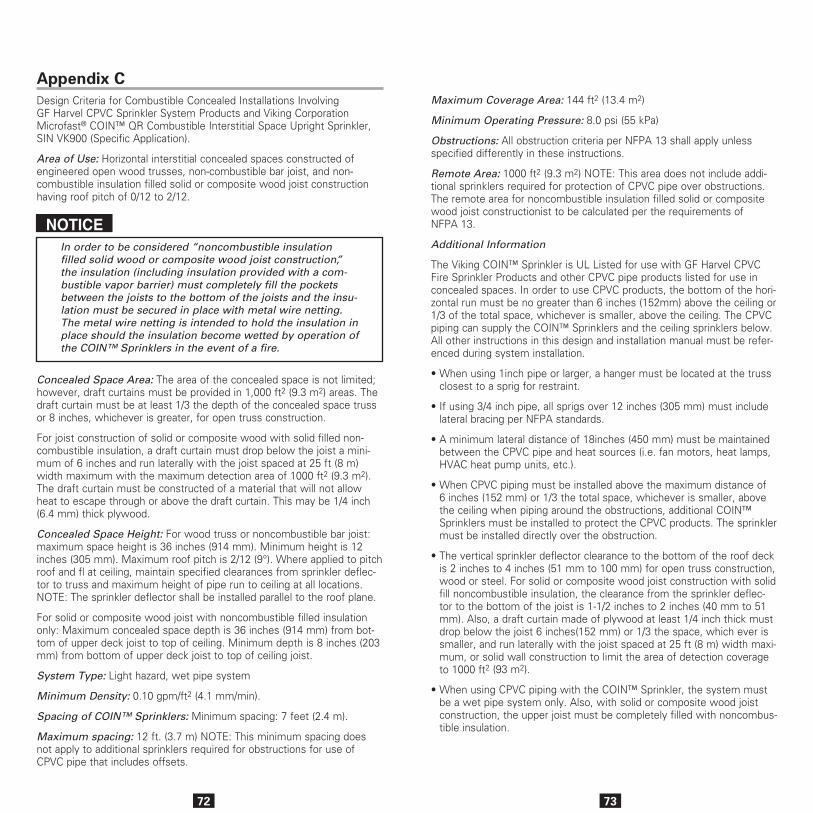
72
Appendix CDesign Criteria for Combustible Concealed Installations Involving GF Harvel CPVC Sprinkler System Products and Viking Corporation Microfast® COIN™ QR Combustible Interstitial Space Upright Sprinkler, SIN VK900 (Specific Application).
Area of Use: Horizontal interstitial concealed spaces constructed of engineered open wood trusses, non-combustible bar joist, and non- combustible insulation filled solid or composite wood joist construction having roof pitch of 0/12 to 2/12.
NOTICEIn order to be considered “noncombustible insulation filled solid wood or composite wood joist construction,” the insulation (including insulation provided with a com-bustible vapor barrier) must completely fill the pockets between the joists to the bottom of the joists and the insu-lation must be secured in place with metal wire netting. The metal wire netting is intended to hold the insulation in place should the insulation become wetted by operation of the COIN™ Sprinklers in the event of a fire.
Concealed Space Area: The area of the concealed space is not limited; however, draft curtains must be provided in 1,000 ft2 (9.3 m2) areas. The draft curtain must be at least 1/3 the depth of the concealed space truss or 8 inches, whichever is greater, for open truss construction.
For joist construction of solid or composite wood with solid filled non-combustible insulation, a draft curtain must drop below the joist a mini-mum of 6 inches and run laterally with the joist spaced at 25 ft (8 m) width maximum with the maximum detection area of 1000 ft2 (9.3 m2). The draft curtain must be constructed of a material that will not allow heat to escape through or above the draft curtain. This may be 1/4 inch (6.4 mm) thick plywood.
Concealed Space Height: For wood truss or noncombustible bar joist: maximum space height is 36 inches (914 mm). Minimum height is 12 inches (305 mm). Maximum roof pitch is 2/12 (9°). Where applied to pitch roof and fl at ceiling, maintain specified clearances from sprinkler deflec-tor to truss and maximum height of pipe run to ceiling at all locations. NOTE: The sprinkler deflector shall be installed parallel to the roof plane.
For solid or composite wood joist with noncombustible filled insulation only: Maximum concealed space depth is 36 inches (914 mm) from bot-tom of upper deck joist to top of ceiling. Minimum depth is 8 inches (203 mm) from bottom of upper deck joist to top of ceiling joist.
System Type: Light hazard, wet pipe system
Minimum Density: 0.10 gpm/ft2 (4.1 mm/min).
Spacing of COIN™ Sprinklers: Minimum spacing: 7 feet (2.4 m).
Maximum spacing: 12 ft. (3.7 m) NOTE: This minimum spacing does not apply to additional sprinklers required for obstructions for use of CPVC pipe that includes offsets.
73
Maximum Coverage Area: 144 ft2 (13.4 m2)
Minimum Operating Pressure: 8.0 psi (55 kPa)
Obstructions: All obstruction criteria per NFPA 13 shall apply unless specified differently in these instructions.
Remote Area: 1000 ft2 (9.3 m2) NOTE: This area does not include addi-tional sprinklers required for protection of CPVC pipe over obstructions. The remote area for noncombustible insulation filled solid or composite wood joist constructionist to be calculated per the requirements of NFPA 13.
Additional Information
The Viking COIN™ Sprinkler is UL Listed for use with GF Harvel CPVC Fire Sprinkler Products and other CPVC pipe products listed for use in concealed spaces. In order to use CPVC products, the bottom of the hori-zontal run must be no greater than 6 inches (152mm) above the ceiling or 1/3 of the total space, whichever is smaller, above the ceiling. The CPVC piping can supply the COIN™ Sprinklers and the ceiling sprinklers below. All other instructions in this design and installation manual must be refer-enced during system installation.
• When using 1inch pipe or larger, a hanger must be located at the truss closest to a sprig for restraint.
• If using 3/4 inch pipe, all sprigs over 12 inches (305 mm) must include lateral bracing per NFPA standards.
• A minimum lateral distance of 18inches (450 mm) must be maintained between the CPVC pipe and heat sources (i.e. fan motors, heat lamps, HVAC heat pump units, etc.).
• When CPVC piping must be installed above the maximum distance of 6 inches (152 mm) or 1/3 the total space, whichever is smaller, above the ceiling when piping around the obstructions, additional COIN™ Sprinklers must be installed to protect the CPVC products. The sprinkler must be installed directly over the obstruction.
• The vertical sprinkler deflector clearance to the bottom of the roof deck is 2 inches to 4 inches (51 mm to 100 mm) for open truss construction, wood or steel. For solid or composite wood joist construction with solid fill noncombustible insulation, the clearance from the sprinkler deflec-tor to the bottom of the joist is 1-1/2 inches to 2 inches (40 mm to 51 mm). Also, a draft curtain made of plywood at least 1/4 inch thick must drop below the joist 6 inches(152 mm) or 1/3 the space, which ever is smaller, and run laterally with the joist spaced at 25 ft (8 m) width maxi-mum, or solid wall construction to limit the area of detection coverage to 1000 ft2 (93 m2).
• When using CPVC piping with the COIN™ Sprinkler, the system must be a wet pipe system only. Also, with solid or composite wood joist construction, the upper joist must be completely filled with noncombus-tible insulation.
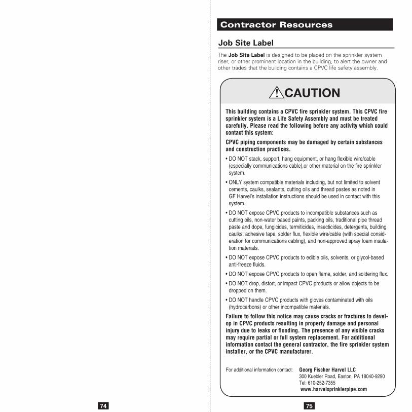
74 75
Job Site LabelThe Job Site Label is designed to be placed on the sprinkler system riser, or other prominent location in the building, to alert the owner and other trades that the building contains a CPVC life safety assembly.
Contractor Resources
This building contains a CPVC fire sprinkler system. This CPVC fire sprinkler system is a Life Safety Assembly and must be treated carefully. Please read the following before any activity which could contact this system:
CPVC piping components may be damaged by certain substances and construction practices.
• DO NOT stack, support, hang equipment, or hang flexible wire/cable (especially communications cable),or other material on the fire sprinkler system.
• ONLY system compatible materials including, but not limited to solvent cements, caulks, sealants, cutting oils and thread pastes as noted in GF Harvel’s installation instructions should be used in contact with this system.
• DO NOT expose CPVC products to incompatible substances such as cutting oils, non-water based paints, packing oils, traditional pipe thread paste and dope, fungicides, termiticides, insecticides, detergents, building caulks, adhesive tape, solder flux, flexible wire/cable (with special consid-eration for communications cabling), and non-approved spray foam insula-tion materials.
• DO NOT expose CPVC products to edible oils, solvents, or glycol-based anti-freeze fluids.
• DO NOT expose CPVC products to open flame, solder, and soldering flux.
• DO NOT drop, distort, or impact CPVC products or allow objects to be dropped on them.
• DO NOT handle CPVC products with gloves contaminated with oils (hydrocarbons) or other incompatible materials.
Failure to follow this notice may cause cracks or fractures to devel-op in CPVC products resulting in property damage and personal injury due to leaks or flooding. The presence of any visible cracks may require partial or full system replacement. For additional information contact the general contractor, the fire sprinkler system installer, or the CPVC manufacturer.
For additional information contact: Georg Fischer Harvel LLC300 Kuebler Road, Easton, PA 18040-9290Tel: 610-252-7355 www.harvelsprinklerpipe.com
!
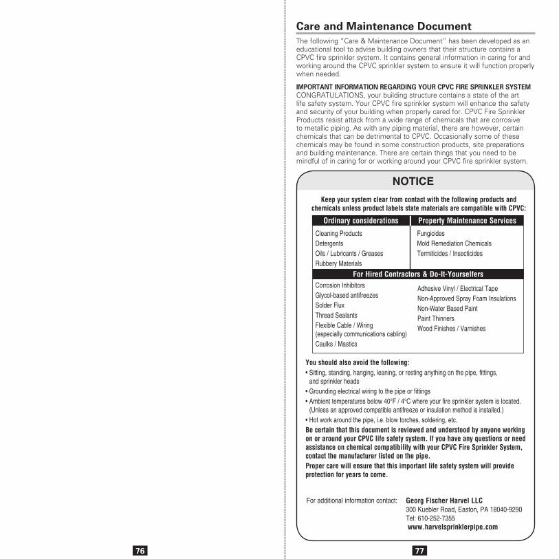
76 77
Care and Maintenance DocumentThe following “Care & Maintenance Document” has been developed as an educational tool to advise building owners that their structure contains a CPVC fire sprinkler system. It contains general information in caring for and working around the CPVC sprinkler system to ensure it will function properly when needed.
IMPORTANT INFORMATION REGARDING YOUR CPVC FIRE SPRINKLER SYSTEM CONGRATULATIONS, your building structure contains a state of the art life safety system. Your CPVC fire sprinkler system will enhance the safety and security of your building when properly cared for. CPVC Fire Sprinkler Products resist attack from a wide range of chemicals that are corrosive to metallic piping. As with any piping material, there are however, certain chemicals that can be detrimental to CPVC. Occasionally some of these chemicals may be found in some construction products, site preparations and building maintenance. There are certain things that you need to be mindful of in caring for or working around your CPVC fire sprinkler system.
Adhesive Vinyl / Electrical TapeNon-Approved Spray Foam Insulations Non-Water Based Paint Paint Thinners Wood Finishes / Varnishes
Keep your system clear from contact with the following products and chemicals unless product labels state materials are compatible with CPVC:
Cleaning Products Fungicides Detergents Mold Remediation Chemicals Oils / Lubricants / Greases Termiticides / InsecticidesRubbery Materials
Corrosion Inhibitors Glycol-based antifreezesSolder Flux Thread SealantsFlexible Cable / Wiring (especially communications cabling) Caulks / Mastics
You should also avoid the following: • Sitting, standing, hanging, leaning, or resting anything on the pipe, fittings,
and sprinkler heads • Grounding electrical wiring to the pipe or fittings • Ambient temperatures below 40°F / 4°C where your fire sprinkler system is located.
(Unless an approved compatible antifreeze or insulation method is installed.) • Hot work around the pipe, i.e. blow torches, soldering, etc. Be certain that this document is reviewed and understood by anyone working on or around your CPVC life safety system. If you have any questions or need assistance on chemical compatibility with your CPVC Fire Sprinkler System, contact the manufacturer listed on the pipe.Proper care will ensure that this important life safety system will provide protection for years to come.
Ordinary considerations Property Maintenance Services
For Hired Contractors & Do-It-Yourselfers
NOTICE
For additional information contact: Georg Fischer Harvel LLC300 Kuebler Road, Easton, PA 18040-9290Tel: 610-252-7355 www.harvelsprinklerpipe.com

79
AIR OR COMPRESSED GAS MUST NEVER BE USED FOR SYSTEM ACCEPTANCE TESTING (HYDROSTATIC PRESSURE TEST). SYSTEM FAILURE WHEN USING COMPRESSED AIR/GAS FOR SYSTEM ACCEPTANCE TESTING CAN RESULT IN BODILY INJURY, DEATH AND/OR PROPERTY DAMAGE.
The data furnished herein is provided as a courtesy and is based on past experiences, limited testing, and other information believed to be reliable. This information may be considered as a basis for recommendation only. No guarantee is made as to its accuracy, suitability for particular applications, or the results to be obtained therefrom. Materials should be tested under actual service conditions to determine suitability for a particular purpose.
SAFETY ALERT MESSAGES
Several varieties of safety alerts and related messages appear in this catalog. Please be sure you understand the meaning of the keywords that identify each type of alert.
“WARNING” signifies hazards or unsafe practices that can cause severe personal injury or death if instructions, including recommended precautions, are not fol-lowed.
“CAUTION” signifies hazards or unsafe practices that can cause minor injury or product or property damage if instruc-tions, including recommended precau-tions, are not followed.
Use of the word “NOTICE” signifies important special instructions.
NOTICE
BlazeMaster® is a registered trademark of The Lubrizol Corporation.Soffi-Steel® is a registered trademark of Grice Engineering, Inc.
©2012 Georg Fischer Harvel LLC. All Rights Reserved.
8/22/12(10M); REP4/12/10(15M); 1/1/09(10M)
300 Kuebler RoadEaston, Pa 18044-0757phone: 610-252-7355fax: 610-253-4436